Embed Size (px)
Citation preview

Waveform-Based Coding:Transform and Predictive Coding
(single frames)(Sections 9.1.1-9.2.3)
Yao WangPolytechnic University, Brooklyn, NY11201

Outline
• Overview of video coding systems• Transform coding• Predictive coding

3
Components in a Coding System
Focus of this lecture

4
Transform Coding
• Motivation: – Represent a vector (e.g. a block of image samples) as the
superposition of some typical vectors (block patterns)– Quantize and code the coefficients– Can be thought of as a constrained vector quantizer
+t1 t2 t3 t4
5
Block Diagram

6
What Transform Basis to Use?
• The transform should– Minimize the correlation among resulting coefficients, so that
scalar quantization can be employed without losing too much in coding efficiency compared to vector quantization
– Compact the energy into as few coefficients as possible
• Optimal transform – Karhunan Loeve Transform (KLT): signal statistics
dependent
• Suboptimal transform– Discrete Cosine transform (DCT): nearly as good as KLT for
common image signals

7
General Linear Transform
• Basis vectors (or blocks):
• Inverse transform represents a vector or block as the superposition of basis vectors or blocks
• Forward transform determines the contribution (weight) of each basis vector

8
Unitary Transform
• Unitary (orthonormal) basis: – Basis vectors are orthogonal to each other and each has length 1
• Transform coefficient associated with a basis vector is simply the projection of the input vector onto the basis vector

9
Unitary Transform
• Recall– 1D DFT – Discrete Fourier Transform (zig-zag order)– 2D DFT– Separable Transforms– DCT – Discrete Cosine Transform– 1D or 2D

10
Discrete Cosine Transform: Basis Images

11
Discrete Cosine Transform: Basis Images
8x8

12
Energy Distribution of DCT Coefficients in Typical Images

13
Images Approximated by Different Number of DCT Coefficients
Original
With 8/64Coefficients
With 16/64Coefficients
With 4/64Coefficients
14
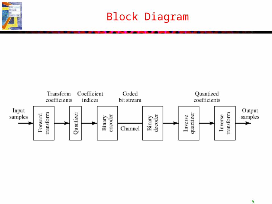
Distortion in Transform Coding
• Distortion in sample domain
TTttTTtt
SSssSSss
tsTStsTS
nnnn
nnnn
knkn
,,, of versionsquantizedrepresent ˆ,ˆ,ˆ,ˆ,,, of versionsquantizedrepresent ˆ,ˆ,ˆ,ˆ
, toingcorrespond vectorsrandom ,, toingcorrespond RVs denote ,

15
Distortion in Transform Coding
• Distortion in coefficient domain
• The two distortion equals with unitary transform (similar to energy preservation equations in FT)

16
Modeling of Distortion Due to Coefficient Quantization
• High Resolution Approximation of Scalar Quantization – With the MMSE quantizer, when each coefficient is scalar
quantized with sufficient high rates, so that the pdf in each quantization bin is approximately flat
Depends on the pdf of the k-th coefficient.

17
Optimal Bit Allocation Among Coefficients
• How Many Bits to Use For Each Coefficient? – Can be formulated as an constrained optimization problem:
Minimize:
Subject to:
kk
RC
TRRNNR
D
t coefficien ofdistorion - bits total- ts;coefficien ofnumber - rate;bit average -
coding transformusing distortion average -

18
Implication of Optimal Bit Allocation
• Bit rate for a coefficient proportional to its variance (energy)
• Distortion is equalized among all coefficients and depends on the geometric mean of the coefficient variances
Geometric mean
19
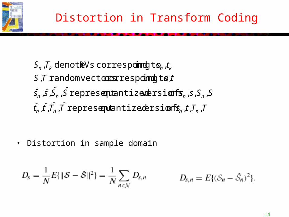
Optimal Transform
• Optimal transform – Should minimize the distortion for a given average bit rate– Equivalent to minimize the geometric mean of the coefficient variances
• When the source is Gaussian, the optimal transform is the Karhunan-Loeve transform, which depends on the covariance matrix between samples
– Basis vectors are the eigen vectors of the covariance matrix, the coefficient variances are the eigen values

20
JPEG Image Coder
• Uses 8x8 DCT• Each coefficient is quantized using a uniform
quantizer, but the step sizes vary based on coefficient variances and their visual importance
• Quantized coefficients are converted into binary bitstreams using runlength coding plus Huffman coding

21
Perceptual based quantization matrix: Zig-zag ordering of DCT coefficients:
Runlength coding example:
JPEG: a bit more detail

22
Predictive Coding
• Motivation: Predicts a sample from past samples and quantize and code the error only
• If the prediction error is typically small, then it can be represented with a lower average bit rate
• Optimal predictor: minimize the prediction error

23
Encoder and Decoder Block Diagram(Closed Loop Prediction)

24
Distortion in Predictive Coder
• With closed-loop prediction, reconstruction error in a sample is equal to the quantization error for the prediction error.
qpppq eeeee ˆ ;for error on quantizati -
Reconstructed value
qs esse ˆerror tedreconstruc Hence,

25
Optimal Predictor
• Question: what predictor should we use?– Minimize the bit rate for coding the prediction error– Because quantization error with a given bit rate depends on
the variance of the signal, minimizing the quantization error = minimizing the prediction error variance.
– Usually linear predictors– Linear minimum mean square error estimator (LMMSE)– Text has more details

26
Predictive Coding for Video
• For video, we apply prediction both among pixels in the same frame (intra-prediction or spatial prediction), but also among pixels in adjacent frames (inter-prediction or temporal prediction)
• Temporal prediction is done with motion compensation