Embed Size (px)
Citation preview

Video Compressive Sensing with On-Chip Programmable Subsampling
Leonidas Spinoulas Kuan He Oliver Cossairt Aggelos Katsaggelos
Department of Electrical Engineering and Computer Science, Northwestern University
2145 Sheridan Road, Evanston, IL 60208, USA
Abstract
The maximum achievable frame-rate for a video camera
is limited by the sensor’s pixel readout rate. The same sen-
sor may achieve either a slow frame-rate at full resolution
(e.g., 60 fps at 4 Mpixel resolution) or a fast frame-rate at
low resolution (e.g., 240 fps at 1 Mpixel resolution). Higher
frame-rates are achieved using pixel readout modes (e.g.,
subsampling or binning) that sacrifice spatial for temporal
resolution within a fixed bandwidth. A number of compres-
sive video cameras have been introduced to overcome this
fixed bandwidth constraint and achieve high frame-rates
without sacrificing spatial resolution. These methods use
electro-optic components (e.g., LCoS, DLPs, piezo actua-
tors) to introduce high speed spatio-temporal multiplexing
in captured images. Full resolution, high speed video is
then restored by solving an undetermined system of equa-
tions using a sparse regularization framework. In this work,
we introduce the first all-digital temporal compressive video
camera that uses custom subsampling modes to achieve
spatio-temporal multiplexing. Unlike previous compressive
video cameras, ours requires no additional optical compo-
nents, enabling it to be implemented in a compact package
such as a mobile camera module. We demonstrate results
using a TrueSense development kit with a 12 Mpixel sensor
and programmable FPGA read out circuitry.
1. Introduction
The subdivision of time by motion picture cameras, the
frame-rate, limits the temporal resolution that can be re-
solved by a camera system. Although frame-rates over 30
frames-per-second (fps) are widely recognized to be imper-
ceptible to human eyes, high speed motion picture capture
has long been a goal in scientific imaging and cinematog-
raphy communities. The ability to resolve motion beyond
what the human eye can see has great scientific and aes-
thetic value, as demonstrated by the recent popularity of
slow motion videos available online. The ever decreasing
hardware prices have enabled significant increase in video
capture rates. Nevertheless, fundamental limitations still
bound the maximum achievable frame-rates as well as the
cost and availability of high speed cameras. Recent ad-
vances in compressed sensing have opened up new frontiers
for achieving high frame-rates beyond those possible by di-
rect Nyquist sampling. In this work we demonstrate videos
at frame-rates of 250 fps using a TrueSense KAC-12040 de-
velopment kit. The development kit includes a FPGA that
can be programmed on the fly to change pixel sub-sampling
modes at extremely high speeds. This allows us to effec-
tively apply spatio-temporal multiplexing on-chip without
the need for any additional optical components (e.g., LCoS,
DLP, or relay optics). Unlike previous compressive video
cameras, our system is entirely digital; it requires no addi-
tional optics, and can be implemented with the same com-
pact package and low cost of today’s mobile camera mod-
ules. We believe our method is the first to bring compressive
video capture within the realm of commercial viability.
1.1. Related Work
There is a long history of research in using computa-
tional methods to increase camera frame-rates. In [3], the
authors used a hybrid approach that combines a low-speed,
high-resolution camera with a high-speed, low-resolution
camera. Gupta et al. used a high-speed DLP projector
coupled with a low-speed camera to increase its effective
frame-rate [7]. Bub et al. used a similar approach to in-
crease the frame-rate of microscopy systems [4] by using a
DLP to modulate a relayed image of the sample. Wilburn
et al. [13] and Agarwal et al. [2] employed camera arrays
to capture high speed video. For all aforementioned tech-
niques, frame-rate increase results by either sacrificing spa-
tial resolution, or by utilizing multiple cameras.
More recently, a number of researchers have developed
systems capable of recovering high-frame-rate video us-
ing compressive coded measurements. These techniques
use a single camera system and aim at reconstructing a
video sequence without sacrificing spatial resolution. At
the heart of these techniques is the principle that an under-
determined system of equations can be solved accurately
49978-1-4673-6759-2/15/$31.00 ©2015 IEEE
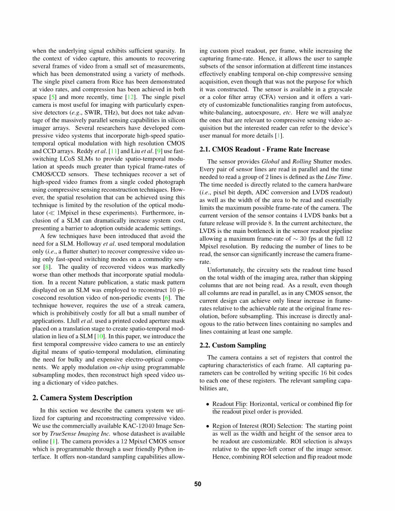
when the underlying signal exhibits sufficient sparsity. In
the context of video capture, this amounts to recovering
several frames of video from a small set of measurements,
which has been demonstrated using a variety of methods.
The single pixel camera from Rice has been demonstrated
at video rates, and compression has been achieved in both
space [5] and more recently, time [12]. The single pixel
camera is most useful for imaging with particularly expen-
sive detectors (e.g., SWIR, THz), but does not take advan-
tage of the massively parallel sensing capabilities in silicon
imager arrays. Several researchers have developed com-
pressive video systems that incorporate high-speed spatio-
temporal optical modulation with high resolution CMOS
and CCD arrays. Reddy et al. [11] and Liu et al. [9] use fast-
switching LCoS SLMs to provide spatio-temporal modu-
lation at speeds much greater than typical frame-rates of
CMOS/CCD sensors. These techniques recover a set of
high-speed video frames from a single coded photograph
using compressive sensing reconstruction techniques. How-
ever, the spatial resolution that can be achieved using this
technique is limited by the resolution of the optical modu-
lator (≪ 1Mpixel in these experiments). Furthermore, in-
clusion of a SLM can dramatically increase system cost,
presenting a barrier to adoption outside academic settings.
A few techniques have been introduced that avoid the
need for a SLM. Holloway et al. used temporal modulation
only (i.e., a flutter shutter) to recover compressive video us-
ing only fast-speed switching modes on a commodity sen-
sor [8]. The quality of recovered videos was markedly
worse than other methods that incorporate spatial modula-
tion. In a recent Nature publication, a static mask pattern
displayed on an SLM was employed to reconstruct 10 pi-
cosecond resolution video of non-periodic events [6]. The
technique however, requires the use of a streak camera,
which is prohibitively costly for all but a small number of
applications. Llull et al. used a printed coded aperture mask
placed on a translation stage to create spatio-temporal mod-
ulation in lieu of a SLM [10]. In this paper, we introduce the
first temporal compressive video camera to use an entirely
digital means of spatio-temporal modulation, eliminating
the need for bulky and expensive electro-optical compo-
nents. We apply modulation on-chip using programmable
subsampling modes, then reconstruct high speed video us-
ing a dictionary of video patches.
2. Camera System Description
In this section we describe the camera system we uti-
lized for capturing and reconstructing compressive video.
We use the commercially available KAC-12040 Image Sen-
sor by TrueSense Imaging Inc. whose datasheet is available
online [1]. The camera provides a 12 Mpixel CMOS sensor
which is programmable through a user friendly Python in-
terface. It offers non-standard sampling capabilities allow-
ing custom pixel readout, per frame, while increasing the
capturing frame-rate. Hence, it allows the user to sample
subsets of the sensor information at different time instances
effectively enabling temporal on-chip compressive sensing
acquisition, even though that was not the purpose for which
it was constructed. The sensor is available in a grayscale
or a color filter array (CFA) version and it offers a vari-
ety of customizable functionalities ranging from autofocus,
white-balancing, autoexposure, etc. Here we will analyze
the ones that are relevant to compressive sensing video ac-
quisition but the interested reader can refer to the device’s
user manual for more details [1].
2.1. CMOS Readout Frame Rate Increase
The sensor provides Global and Rolling Shutter modes.
Every pair of sensor lines are read in parallel and the time
needed to read a group of 2 lines is defined as the Line Time.
The time needed is directly related to the camera hardware
(i.e., pixel bit depth, ADC conversion and LVDS readout)
as well as the width of the area to be read and essentially
limits the maximum possible frame-rate of the camera. The
current version of the sensor contains 4 LVDS banks but a
future release will provide 8. In the current architecture, the
LVDS is the main bottleneck in the sensor readout pipeline
allowing a maximum frame-rate of ∼ 30 fps at the full 12Mpixel resolution. By reducing the number of lines to be
read, the sensor can significantly increase the camera frame-
rate.
Unfortunately, the circuitry sets the readout time based
on the total width of the imaging area, rather than skipping
columns that are not being read. As a result, even though
all columns are read in parallel, as in any CMOS sensor, the
current design can achieve only linear increase in frame-
rates relative to the achievable rate at the original frame res-
olution, before subsampling. This increase is directly anal-
ogous to the ratio between lines containing no samples and
lines containing at least one sample.
2.2. Custom Sampling
The camera contains a set of registers that control the
capturing characteristics of each frame. All capturing pa-
rameters can be controlled by writing specific 16 bit codes
to each one of these registers. The relevant sampling capa-
bilities are,
• Readout Flip: Horizontal, vertical or combined flip for
the readout pixel order is provided.
• Region of Interest (ROI) Selection: The starting point
as well as the width and height of the sensor area to
be readout are customizable. ROI selection is always
relative to the upper-left corner of the image sensor.
Hence, combining ROI selection and flip readout mode
50

(0,0) (0,0)
(0,0)(0,0)
Selected ROI Selected ROI
Selected ROISelected ROI
No Flip Horizontal Flip
Both FlipsVertical Flip
Figure 1. Flipping and Bayer Pattern Positioning using constant
parameters ROI parameters (starting point, height and width). The
flipping operation combined with constant ROI parameters virtu-
ally implements optical flipping.
No Flip Horizontal Flip
Both FlipsVertical Flip
Figure 2. Combining subsampling and flipping to capture a cen-
tralized ROI.
No ROI Shift Horizontal ROI Shift
Both ROI ShiftsVertical ROI Shift
Figure 3. Combining subsampling and ROI shifts to capture a cen-
tralized ROI.
virtually implements optical flipping when the ROI pa-
rameters are kept constant. The constraints for the ROI
selection are,
1. Horizontal starting point (X) and width (W )
must be multiples of 8.
2. Vertical starting point (Y ) and height (H) must
be multiples of 2.
• Subsampling: Any M out of N subsampling, where
M and N are even numbers up to 32 and M < N is
provided. The subsampling parameters M and N are
the same in both directions. Additionally, the subsam-
pling starting point is always the same as the ROI start-
ing point. Therefore, one can shift the subsampling
pattern in both directions by modifying the starting
point of the ROI, adhering however to the constraints
presented above. The constraints for the subsampling
selection are,
1. N must exactly divide both the W and H of the
ROI.
2. The resulting smaller dimension after subsam-
pling must be greater than 200 pixels.
3. The resulting dimensions after subsampling fol-
low the modulo 8 and modulo 2 rules of the Wand H , respectively. Therefore, the resulting size
after subsampling might be slightly modified au-
tomatically by the sensor hardware.
Figures 1, 2 and 3 summarize the custom sampling ca-
pabilities of the camera by presenting illustrative examples.
Figure 1 shows the relative positioning of the ROI with re-
spect to the starting point (0, 0) of the CMOS sensor array.
One can observe that the application of the same ROI with
the combination of flipping leads to sampling different parts
of the image. Figure 2 presents an example of sampling
the central ROI of the scene by combining subsampling and
the flipping operation. Figure 3 describes the capturing of
the same ROI by combining subsampling and shifts for the
starting point of the ROI. Obviously, for Figures 2 and 3, if
the frames exhibit motion, the measurements will not corre-
spond to the original ROI of a single frame but rather con-
tain combined information from different areas of the se-
quential frames. As mentioned above, the ROI positioning
must adhere to certain rules, hence not allowing shifts at all
possible locations. Therefore, in order to capture a scene
at finer resolutions, subsampling, flipping and ROI shifts
must all be combined. Based on the presented constraints,
the finer resolution one can sample is 4 × 4 pixels in each
16×16 block of each frame. With appropriate combination
of flips and ROI shifts, the total area of a 16× 16 block can
be covered in 16 frames. Such sampling enables a 4× in-
crease in frame-rate while sampling 1/16 of the total pixels
per frame and we refer to it as 4 out of 16 subsampling.
51

Frame Sequence
Bayer
B&W
CFA Pattern(Sensor Defined)
Subsampling Measurements
Figure 5. Measurement Model
RESET
STANDBY
CONFIG
IDLE
RUNNING
WAKE-UP(50ms)
150たs<2たs
<2たs
<35たs
RUNNING mode OR
TRIGGER pin <50たs
TRIG_WAIT
EXT_INT
READOUT
<2たs
End of Acquisition
IDLE mode AND
NO TRIGGER
End of
Acquisition
Slave Integration Mode
Figure 4. Sensor State Diagram, replicated from [1].
2.3. Sensor States
The image sensor cycles through a predefined series of
states that allow the sequence of reading frames and writing
registers to be customizable. A diagram of the various sen-
sor states is presented in Figure 4. As shown in the diagram,
the sensor offers two different methods for cycling between
reading frames or writing registers, specifically using a soft
trigger or an external trigger. The soft trigger refers to the
cycling between the IDLE and RUNNING states and can be
achieved by simple Python commands. The external-trigger
refers to the Slave Integration Mode (see Figure 4) and one
can trigger a frame capture using a virtual command for an
external trigger or an actual signal trigger through a pro-
vided external pin. In the soft-trigger mode, the exposure
time is defined by writing an appropriate value to a register
while in the Slave Integration Mode, exposure is dictated by
the external signal’s ON state. Based on our experience with
the sensor, the slave integration mode was sometimes unsta-
ble resulting to variable frame-rates, therefore we used the
soft-trigger mode. One drawback of the soft trigger mode
is that the FPGA needs to communicate with the connected
computer through USB, hence introducing a latency which
does not allow reaching the maximum possible frame-rate.
Moreover, register reads and writes are only allowed on cer-
tain sensor states. Specifically, the ROI and subsampling
parameters can all be programmed in the IDLE state while
the readout flip option can only be programmed after re-
turning to the CONFIG state. Therefore, writing or reading
registers can introduce extra latency combined with the la-
tency imposed by the communication of the Python inter-
face to the sensor each time a register change command is
sent. Due to these latencies, in our forthcoming discussion
we mainly focus on the proof of concept of using the True-
Sense kit as a compressive sensing video architecture rather
than trying to achieve the maximal frame-rates proposed by
the specifications of the manufacturer.
3. Camera Model for Compressive Sensing
Based on the analyzed imaging capabilities in section 2
we wish to perform temporal compressive sensing acquisi-
tion of a video sequence. A special characteristic of this
compressive video architecture is that the video data cube is
not summed across time as in similar approaches [10]. In-
stead, the full video datacube is subsampled in the 3-D or
4-D space, for grayscale or color images, respectively.
The forward measurement model is illustrated in Fig-
ure 5. Denoting the unknown video data cube by V :h×w× d× t, where h, w, d and t represent height, width,
depth and time, respectively and its vectorized version v,
the forward measurement model can be written as,
y = ΦBv, (1)
where B represents the Bayer pattern operator or the Iden-
tity matrix, depending on whether the data cube v is RGB or
52

Grayscale, respectively, Φ represents the measurement ma-
trix (sequence of sampling patterns) and y is the obtained
measurement vector. Note that the obtained measurements
are not degraded and therefore can be trusted completely
and need not be reconstructed.
4. Reconstruction Algorithm
In our work we did not employ sparsity in order to mini-
mize computational cost since sparsity inducing algorithms
are usually costly. Especially considering the very high res-
olution of the sensor, optimization using sparsity-based ap-
proaches would be prohibitively time consuming. Instead,
since a set of measurements are already known and accu-
rately measured, we utilize a simple least-squares approach
for reconstruction purposes. Nevertheless, we employ a dic-
tionary of patches, commonly used in compressive sens-
ing approaches in order to make our solution space more
constrained. Specifically, we use a 7 × 7 × 16 dictionary
of patches representing a learned dictionary over a set of
videos for a sequence of 16 frames. We obtained this dic-
tionary by the authors in [9]. However, we only find a set of
7×7×16 = 784 linear independent columns and use these
for reconstruction. Since the columns are linearly indepen-
dent, the known part of the solution is guaranteed to be ex-
act, whereas the remaining missing areas are expected to
be covered by meaningful information since they have been
selected by a dictionary trained for video sequences. Note,
that an ℓ1 minimization approach would approximate the
known samples (i.e., not yield exact reconstruction) while
not providing any extra information regarding the missing
samples. This further supports our choice of a least-squares
approach for reconstruction purposes.
Vector Bv from equation (1) can be analyzed as,
Bv = TD
VDTD
Ma, (2)
where a is a vector of coefficients that can represent the
data cube v using elements of the dictionary D, TD
Mis an
operator that converts vector a into a matrix and TD
Vis an
operator which re-vectorizes the resulting matrix DTD
Ma,
after averaging overlapping patches, if any.
Denoting D = TD
VDTD
M, we have,
y = ΦDa, (3)
therefore a can be solved using least-squares as,
a = argmina
∥
∥
∥y − ΦDa
∥
∥
∥
2
2
. (4)
Equation (4) can be efficiently solved using the Conjugate
Gradient method. Finally, the unknown video can be ob-
tained as,
v = BT Da, (5)
Figure 6. Original single frames for the reconstructed frames in
Figure 8, obtained from [12].
where the transpose of the Bayer operator BT denotes the
demosaicing operation (i.e., converting a CFA pattern im-
age to RGB using demosaicing).
4.1. Algorithm Details
Since we aim at reconstructing video sequences of high
spatial resolution, reconstruction speed is a major issue.
In order to further minimize computational cost, we pre-
process the captured measurements by taking temporal dif-
ferences between the frames that have been sampled with
the same sampling pattern. Then by thresholding we cat-
egorize the image blocks into foreground or background.
The background can be easily reconstructed directly by
summing the measured data along the time direction. For
the foreground labeled areas, the minimization problem in
(4) is applied. Furthermore, we utilize spatially overlapping
patches but avoid full sliding overlap by selecting a set of
patch locations at random in each 7 × 7 area, equal to the
patch size of the utilized dictionary. Finally, the reconstruc-
tion of 16 frames is also performed in a sliding fashion, i.e.,
first frames 1-16 are reconstructed, then 2-17 and so on and
the final results are averaged. These algorithm details are
summarized in Figure 7.
5. Experimental Results
In this section we perform a series of simulations as well
as real experiments to demonstrate our proposed approach.
Figure 8 shows simulated reconstructions for the videos
whose first original frames are presented in Figure 6. Both
video sequences were obtained from [12], have resolution
256× 256 and were sampled using the 4 out of 16 subsam-
pling described in section 2.2. They exhibit slow motion
between frames and the reconstructed frames are of high
quality.
Figures 9 and 10 show real experiments with a moving
metronome with a resolution chart attached to it. Both se-
quences have resolution 752×1008 pixels. They were both
captured using 4 out of 16 subsampling. The first sequence
in Figure 9 contains increasing motion moving from left to
right and it shows that the reconstruction quality can be re-
ally high when the captured video sequence contains mo-
53

Foreground/Background Separation
Frames 1-4 Frames 5-8
Foreground
Background
Frame 1
Frame 1
Frame 2 Frame 3 Frame 4
Reconstruction
Detail
Reconstructed Frames
Reconstructed Foreground using Dictionary Reconstruction
Reconstructed Background using Measurement Averaging
Foreground/Background Combination into Full Frames
Detail
Reconstruction
using Averaging
Reconstruction with
overlapping patches
Frame 2 Frame 3 Frame 4
1 2 3 Dictionary-Sized
patches averaged
at random locations
Figure 7. Illustration of algorithm steps.
Figure 9. Real reconstruction of a moving metronome with resolution 752× 1008 pixels and a frame-rate of 252 fps.
tion that can be effectively captured by the camera’s frame-
rate without blurring. Nevertheless, the right reconstructed
frame exhibits several artifacts showing the limitations of
the camera when the scene movement is too fast to effec-
tively be captured by the camera. Specifically, on the left
side the metronome slows down while accelerating when
moving to the center. Finally, Figure 11 shows closeups for
the sequence presented in Figure 10.
This brings us to the essence of our proposed system.
Most presented systems, like the one in [10] perform tem-
poral multiplexing by summing measurements of the data
cube on a single frame. In our approach the data is subsam-
pled and captured without any motion-blur at high frame-
rates. Comparing our system to the one in [10] we can
mention that it has multiple benefits, such that results are
easily reproducible and the reconstruction algorithm need
not be computationally expensive. Furthermore, the lack of
any additional need for optical elements or masks avoids
alignment issues as well as possible diffraction effects. The
main limitation is that the maximal frame-rate is limited by
the camera’s hardware and cannot be increased further, i.e.,
one can only reconstruct a video sequence at the captured
frame-rate of the subsampled sequence.
6. Conclusions
We have demonstrated the first all-digital implementa-
tion of a temporal compressive video camera. Our proto-
type system is based on the TrueSense KAC-12040 sensor
development kit, which allows programmable pixel read out
modes to be dynamically programmed via FPGA. Previous
54

Figure 10. Real reconstruction of a moving metronome with resolution 752 × 1008 pixels and a frame-rate of 255 fps. Upper row shows
the actual camera measurements, lower row shows the reconstruction.
compressive video cameras used complicated optical setups
with expensive electro-optical components, introducing a
significant barrier to reproducibility. Our system, on the
other hand, requires only an inexpensive ($3K) sensor de-
velopment kit. Code for programming the FPGA (100 lines
of Python code) and reconstructing video (Matlab library)
will be made available on our website so that our experi-
ments may be replicated with minimal effort.
The effective bandwidth achieved by our compressive
video camera is around an order of magnitude greater than
most commercially available sensors today. More impor-
tantly, the sampling method we use can be implemented on
nearly any camera by merely incorporating the appropriate
readout circuitry. We hope that our initial implementation
will encourage camera manufacturers to incorporate more
flexible readout modes into their designs so that compres-
sive video reconstruction may enter into the standard set
of digital processing operations applied to consumer video
capture.
There are several opportunities for improvement in fu-
ture work. The KAC-12040 allowed us to demonstrate the
efficacy of using programmable readout modes for com-
pressive video construction, but ideally the readout modes
would offer even finer granularity of control. Firstly, KAC-
12040 is a high speed sensor based on a parallel column
readout architecture. As a result, M out of N subsam-
pling does not increase frame-rate by a factor of N
M, some-
what limiting the frame-rate increase that can be achieved
using compressive reconstruction. Many consumer cam-
eras, however, are not based on this readout architecture and
would achieve a N
Mframe-rate increase using our approach.
Secondly, the horizontal ROI offset of the KAC-12040 must
be a multiple of 8, severely restricting the sampling patterns
that may be used. We compensate in this paper by sub-
sampling blocks of 4 × 4 pixels, but a more ideal pattern
of 2 × 2 could be achieved with a new FPGA implemen-
tation. In general, co-optimization of subsampling pattern
and readout circuitry design remains an interesting direction
for future work. An ideal optimization strategy would be to
take into account both reconstruction quality and hardware
constraints. For instance, an interesting possibility could be
to sample different sized blocks sequentially (e.g., 2
8, fol-
lowed by 8
16, etc.), but performance would depend on how
efficiently the FPGA could dynamically switch between dif-
ferent frames sizes. We hope that our initial work will spur
further research on the co-design of spatio-temporal sam-
pling patterns and custom pixel read out modes.
References
[1] TrueSense Imaging Inc. KAC-12040 image sensor datasheet.
http://www.truesenseimaging.com. Accessed:
2014-12-26. 2, 4
[2] A. Agrawal, M. Gupta, A. Veeraraghavan, and S. G.
Narasimhan. Optimal coded sampling for temporal super-
resolution. In Proc. IEEE Conf. Comp. Vision Pattern Recog-
nition, pages 599–606, June 2010. 1
[3] M. Ben-Ezra and S. Nayar. Motion-based Motion Deblur-
ring. IEEE Trans. Pattern Anal. Mach. Intell., 26(6):689–
698, Jun. 2004. 1
55

Figure 8. Example of simulated reconstruction; left column shows
the Car-Car sequence and the right column shows the Card-
Monster sequence. All reconstructions were performed using 4
out 16 subsampling. Both sequences were obtained from [12].
[4] G. Bub, M. Tecza, M. Helmes, P. Lee, and P. Kohl. Tem-
poral pixel multiplexing for simultaneous high-speed, high-
resolution imaging. Nature Methods, 7:209–U66, 2010. 1
[5] M. F. Duarte, M. A. Davenport, D. Takhar, J. N. Laska,
T. Sun, K. F. Kelly, and R. G. Baraniuk. Single-Pixel imag-
ing via compressive sampling. IEEE Signal Process. Mag.,
25(2):83–91, Mar. 2008. 2
[6] L. Gao, J. Liang, C. Li, and L. V. Wang. Single-Shot com-
pressed ultrafast photography at one hundred billion frames
Figure 11. Multiple frames for the reconstruction of the
metronome sequence shown in Figure 10.
per second. Nature, 516:74–77, 2014. 2
[7] M. Gupta, A. Agrawal, A. Veeraraghavan, and S. G.
Narasimhan. Flexible voxels for motion-aware videography.
In Proc. European Conf. Comp. Vision, ECCV’10, pages
100–114, Berlin, Heidelberg, 2010. Springer-Verlag. 1
[8] J. Holloway, A. C. Sankaranarayanan, A. Veeraraghavan,
and S. Tambe. Flutter shutter video camera for compressive
sensing of videos. In Proc. IEEE Int. Conf. Comp. Photog-
raphy, pages 1–9, Apr. 2012. 2
[9] D. Liu, J. Gu, Y. Hitomi, M. Gupta, T. Mitsunaga, and S. K.
Nayar. Efficient space-time sampling with pixel-wise coded
exposure for high speed imaging. IEEE Trans. Pattern Anal.
Mach. Intell., 99:1, 2013. 2, 5
[10] P. Llull, X. Liao, X. Yuan, J. Yang, D. Kittle, L. Carin,
G. Sapiro, and D. J. Brady. Coded aperture compressive
56
temporal imaging. Opt. Express, 21(9):10526–10545, May
2013. 2, 4, 6
[11] D. Reddy, A. Veeraraghavan, and R. Chellappa. P2C2: Pro-
grammable pixel compressive camera for high speed imag-
ing. In Proc. IEEE Conf. Comp. Vision Pattern Recognition,
pages 329–336, June 2011. 2
[12] A. C. Sankaranarayanan, C. Studer, and R. G. Baraniuk. CS-
MUVI: Video compressive sensing for spatial-multiplexing
cameras. In Proc. IEEE Int. Conf. Comp. Photography,
pages 1–10, Apr. 2012. 2, 5, 8
[13] B. Wilburn, N. Joshi, V. Vaish, E.-V. Talvala, E. Antunez,
A. Barth, A. Adams, M. Horowitz, and M. Levoy. High per-
formance imaging using large camera arrays. ACM Trans.
Graph., 24(3):765–776, Jul. 2005. 1
57


![[Engelberg] Compressive Sensing](https://img.dokumen.tips/doc/110x75/55cf9985550346d0339dc8ee/engelberg-compressive-sensing.jpg)