Embed Size (px)
Citation preview

Final Report
Video Based Studies of Flexible Traffic Separators at Highway-
Railroad Grade Crossings
Prepared for the Florida Department of Transportation Rail Office
By The University Of Florida Transportation Research Center
April 2003
Technical Report Documentation Page1. Report No. 2. Government Accession No. 3. Recipient's Catalog No.
4. Title and Subtitle 5. Report Date
April 2003 6. Performing Organization Code
Video Based Studies of Flexible Traffic Separators at Highway-Railroad Grade Crossings
8. Performing Organization Report No.
7. Author(s) Byungkon Ko, Kenneth Courage and Morya Willis UFTRC 891-2
9. Performing Organization Name and Address 10. Work Unit No. (TRAIS)
11. Contract or Grant No.
University of Florida Department of Civil and Coastal Engineering 124 Yon Hall / P.O. Box 116580 Gainesville, FL 32611-6580
13. Type of Report and Period Covered 12. Sponsoring Agency Name and Address
Final
14. Sponsoring Agency Code
Florida Department of Transportation Research Management Center 605 Suwannee Street, MS 30 Tallahassee, FL 32301-8064
15. Supplementary Notes
16. AbstractThis report describes a field evaluation of the operation of flexible traffic separator devices installed at three highway-railroad grade crossings in central Florida. The study focused on assessing the effectiveness of the separators in discouraging motorists from violating the warning gates both before the train arrived and after it departed. Other topics of interest to the evaluation included an assessment of the effects on motorist response to the warning devices, general maintenance considerations, and anecdotal events that occurred within the study period. These studies were based on an extensive data collection effort. A prototype surveillance system was developed to obtain the video data at the crossing sites. The components of the system included a set of video cameras, a telescoping mast for mounting the cameras, a portable 12-volt time-lapse videocassette recorder, a 12-volt marine battery for power and a weatherproof cabinet to house the equipment. A series of “before and after” studies was performed at each of the locations. A total of 4,004 hours of video taped operation involving 2,624 train crossing events was observed manually to assess the effectiveness of the traffic separators. The study period was approximately one month before and after the installation of the separators at each site. It was observed that that a total of 25 vehicles drove around the gates in the period before the traffic separator installation, and only one vehicle was involved in this type of violation afterwards. The violation rates prior to the separator installation were very low in comparison with other studies reported in the literature. The reduction in violations from 25 to 1 was statistically significant. Only one of the three locations experienced maintenance problems during the course of the study. The narrow pavement and rural cross section at this location was thought to have contributed to the problem.
17. Key Words 18. Distribution Statement
Railroad grade crossings, warning gates, traffic separators, video surveillance, traffic studies..
No restrictions. This document is available to the public through the National Technical Information Service, Springfield, VA, 22161
19 Security Classif. (of this report) 20 Security Classif. (of this page) 21.No. of Pages 22 Price
Unclassified Unclassified 105
Form DOTF 1700.7 (8-72) Reproduction of completed form authorized
Development and Deployment of a Portable Highway-
Railroad Grade Crossing Surveillance System
Volume II: Video Based Studies of Flexible Traffic Separators at
Highway-Railroad Grade Crossings
Byungkon Ko
Kenneth Courage and
Morya Willis
Prepared for the Florida Department of Transportation Rail Office
By the University of Florida
Transportation Research Center
April 2003
PREFACE
The Florida Department of Transportation (FDOT) Contract BD243 addresses an immediate requirement for a study of traffic and train operations at three highway-railroad grade crossing sites in central Florida. This requirement is accompanied by a longer term need to develop a simple video surveillance system by which FDOT personnel can conduct similar studies in the future on short notice, and for a specific study to be performed at five locations in a railroad corridor in south Florida. The results of the project are presented in a series of three volumes:
Volume I: A Portable Highway-Railroad Grade Crossing Surveillance System for Operational and Safety Studies
Volume II: Video Based Studies of Flexible Traffic Separators at Highway-Railroad
Grade Crossings
Volume III: Video Based Studies of Highway-Railroad Grade Crossings in the South Florida Railroad Corridor
This document contains Volume II of the series. It describes a field evaluation of the operation of flexible traffic separator devices installed at three highway-railroad grade crossings in central Florida. The study focused on assessing the effectiveness of the separators in discouraging motorists from violating the warning gates both before the train arrived and after it departed.
ACKNOWLEDGEMENTS The University of Florida Transportation Research Center (TRC) conducted this study. The overall effort was coordinated by Prof. Ken Courage, with significant technical support from Mr. Byungkon Ko and Dr. Morya Willis. Mr. H. Michael Dowell, P.E. was the FDOT technical coordinator. The project team acknowledges and appreciates the cooperation of the Tampa Electric Company (TECO) and Florida Power Corp in permitting the use of their utility poles for mounting the surveillance equipment. Special acknowledgement and thanks are also extended to Mr. Ronald J Sullivan and Mr. Larry Turner for their diligent efforts in collecting over 4000 hours of videotape at the three crossing sites.
DISCLAIMER The opinions and findings expressed in this document are those of the authors and not necessarily those of the Florida Department of Transportation or any other government agency.
Video-Based Studies of Flexible Traffic Separators at Highway-Railroad Grade Crossings
Table of Contents
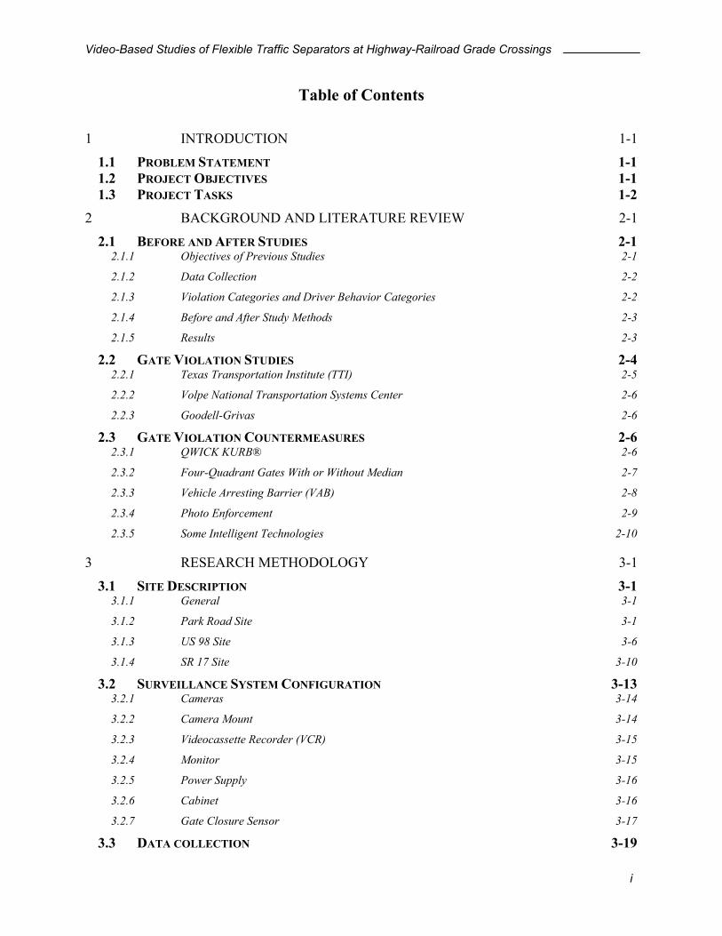
1 INTRODUCTION 1-1
1.1 PROBLEM STATEMENT 1-1 1.2 PROJECT OBJECTIVES 1-1 1.3 PROJECT TASKS 1-2
2 BACKGROUND AND LITERATURE REVIEW 2-1
2.1 BEFORE AND AFTER STUDIES 2-1 2.1.1 Objectives of Previous Studies 2-1 2.1.2 Data Collection 2-2 2.1.3 Violation Categories and Driver Behavior Categories 2-2 2.1.4 Before and After Study Methods 2-3 2.1.5 Results 2-3
2.2 GATE VIOLATION STUDIES 2-4 2.2.1 Texas Transportation Institute (TTI) 2-5 2.2.2 Volpe National Transportation Systems Center 2-6 2.2.3 Goodell-Grivas 2-6
2.3 GATE VIOLATION COUNTERMEASURES 2-6 2.3.1 QWICK KURB® 2-6 2.3.2 Four-Quadrant Gates With or Without Median 2-7 2.3.3 Vehicle Arresting Barrier (VAB) 2-8 2.3.4 Photo Enforcement 2-9 2.3.5 Some Intelligent Technologies 2-10
3 RESEARCH METHODOLOGY 3-1
3.1 SITE DESCRIPTION 3-1 3.1.1 General 3-1 3.1.2 Park Road Site 3-1 3.1.3 US 98 Site 3-6 3.1.4 SR 17 Site 3-10
3.2 SURVEILLANCE SYSTEM CONFIGURATION 3-13 3.2.1 Cameras 3-14 3.2.2 Camera Mount 3-14 3.2.3 Videocassette Recorder (VCR) 3-15 3.2.4 Monitor 3-15 3.2.5 Power Supply 3-16 3.2.6 Cabinet 3-16 3.2.7 Gate Closure Sensor 3-17
3.3 DATA COLLECTION 3-19
i

Video-Based Studies of Flexible Traffic Separators at Highway-Railroad Grade Crossings
3.3.1 Schedule 3-19 3.3.2 Videotape Library 3-20
3.4 DATA REDUCTION AND ANALYSIS 3-21 3.4.1 Manual Observations 3-21 3.4.2 Violation Categories 3-24 3.4.3 Data Spreadsheets 3-28 3.4.4 Video Clips of Hazardous Events 3-28 3.4.5 Study Schedule 3-28
4 STUDY RESULTS 4-1
4.1 ANECDOTAL RESULTS 4-1 4.1.1 Damaged Gate 4-1 4.1.2 QWICK KURB® Hit 4-1 4.1.3 Camera Problems 4-2 4.1.4 Bicycle Violation 4-2 4.1.5 Platoon Violation 4-3 4.1.6 Pedestrian Fatality 4-3 4.1.7 Switching Operation of a Train 4-4 4.1.8 Gate Violation after the Separators Were Installed 4-5
4.2 BEFORE AND AFTER SEPARATOR INSTALLATION ANALYSIS 4-6 4.2.1 Park Road 4-6 4.2.2 US 98 and SR 17 4-14
5 CONCLUSIONS AND RECOMMENDATIONS 5-1
5.1 EFFECTIVENESS OF QWICK KURB® IN PREVENTING DRIVE-AROUND VIOLATIONS 5-1 5.2 OTHER EFFECTS OF QWICK KURB® 5-2 5.3 EFFECTIVENESS OF THE VIDEO SURVEILLANCE SYSTEM 5-2 5.4 RECOMMENDATIONS FOR FURTHER IMPLEMENTATION 5-3 5.5 RECOMMENDATIONS FOR FURTHER STUDIES 5-3
Appendix A: Product Specifications and Literature Appendix B: Florida Laws Related to Highway-Railroad Grade Crossings Appendix C: Captured Video Events Appendix D: Data Analysis Spreadsheets (Delivered separately on CD-ROM)
ii

Video-Based Studies of Flexible Traffic Separators at Highway-Railroad Grade Crossings
List of Figures Figure 2-1: QWICK KURB® Crossing...................................................................................... 2-7 Figure 2-2: Four-Quadrant Gate Railroad Crossing ................................................................... 2-8 Figure 2-3: Vehicle Arresting Barrier at Railroad Crossing....................................................... 2-9 Figure 2-4: Variable Message Sign Board................................................................................ 2-10 Figure 2-5: In-Vehicle Warning Display .................................................................................. 2-11 Figure 2-6: Second Train Warning System .............................................................................. 2-11 Figure 2-7: Four-Quadrant Gate with Automatic Train Stop ................................................... 2-12 Figure 3-1: Map of the Park Road Site ....................................................................................... 3-3 Figure 3-2: Park Road Site Geometry......................................................................................... 3-3 Figure 3-3: Park Road Site from the South (Before Separator Installation)............................... 3-5 Figure 3-4: Park Road Site from the South (After Separator Installation) ................................. 3-5 Figure 3-5: Park Road Site from the North (After Separator Installation) ................................. 3-6 Figure 3-6: Map 1 of the US 98 Site........................................................................................... 3-7 Figure 3-7: Map 2 of the US 98 Site........................................................................................... 3-7 Figure 3-8: US 98 Site Geometry ............................................................................................... 3-8 Figure 3-9: US-98 Site from the East (Before Separator Installation)........................................ 3-9 Figure 3-10: US-98 Site from the West (After Separator Installation)....................................... 3-9 Figure 3-11: Map 1 of US 17 and Alt 27 .................................................................................. 3-10 Figure 3-12: Map 2 of US 17 and Alt 27 .................................................................................. 3-11 Figure 3-13: SR 17 Site Geometry............................................................................................. 3-12 Figure 3-14: SR 17 Site from the Southwest (Before Separator Installation) .......................... 3-12 Figure 3-15: Typical Temporary Traffic Surveillance System................................................. 3-13 Figure 3-16: Cameras Used in the Study .................................................................................. 3-14 Figure 3-17: Camera Mount...................................................................................................... 3-15 Figure 3-18: Monitors ............................................................................................................... 3-16 Figure 3-19: Mounted Cabinet.................................................................................................. 3-17 Figure 3-20: Proposed Enclosure for the Sensor Device .......................................................... 3-18 Figure 3-21: Diagram of Decision Times ................................................................................. 3-26 Figure 4-1: QWICK KURB®..................................................................................................... 4-2 Figure 4-2: Platoon Violation ..................................................................................................... 4-3 Figure 4-3: Pedestrian Approaching Tracks ............................................................................... 4-4 Figure 4-4: Proposed Categories of Violations........................................................................... 4-6 Figure 4-5: Northbound Drive-Around Violation Prior to Train Arrival ................................... 4-8 Figure 4-6: Northbound Drive-Around Violation During Train Switching Operations............. 4-9 Figure 4-7: Southbound Bicycle Warning Gate Violations...................................................... 4-10 Figure 4-8: Crossing and Stopping Driver Behavior Before the Gates are Down (Northbound
Before Separator Installation)............................................................................................. 4-11 Figure 4-9: Crossing and Stopping Driver Behavior Before the Gates are Down (Northbound
After Separator Installation) ............................................................................................... 4-12 Figure 4-10: Probability of Stopping Before the Gates are Down (Northbound Before and After
Separator Installation)......................................................................................................... 4-12 Figure 4-11: Drive-Around Violation at US 98 Site................................................................. 4-15 Figure 4-12: Drive-Around Violation at SR 17 Site................................................................. 4-16
iii
Video-Based Studies of Flexible Traffic Separators at Highway-Railroad Grade Crossings
List of Tables Table 2-1: Objectives of Previous Projects................................................................................. 2-2 Table 2-2: Data Collection Methodology of Previous Projects .................................................. 2-2 Table 2-3: Violation and Driver Behavior Categories of Each Project ...................................... 2-3 Table 2-4: Before and After Separator Installation Study Methods of Each Project.................. 2-4 Table 2-5: Result Summaries by Project .................................................................................... 2-4 Table 2-6: Definitions of Violation Categories .......................................................................... 2-5 Table 3-1: Site Characteristics .................................................................................................... 3-2 Table 3-2: Data Collection Summary ....................................................................................... 3-20 Table 3-3: Timing Parameters for Warning Signals ................................................................. 3-22 Table 3-4: Database Reference Key ......................................................................................... 3-23 Table 3-5: Passage Times (PT) Calculated at Park Road Site (Northbound) ........................... 3-27 Table 3-6: Passage Times (PT) Calculated at Park Road Site (Southbound) ........................... 3-27 Table 4-1: Number of Violating Vehicles Out of Number of Vehicles that had Chance to Violate
on Each Stage (Northbound on Park Road).......................................................................... 4-7 Table 4-2: Number of Violating Vehicles Out of Number of Vehicles that had Chance to Violate
on Each Stage (Southbound on Park Road).......................................................................... 4-7 Table 4-3: Chi-square Test of Significance on Crossing Behavior Before the Gates are Down
(Northbound Before and After Separator Installation)....................................................... 4-13 Table 4-4: Number of Drive-Around Vehicles / Number of Vehicles that had Chance to Violate
Before and After Study (US 98 Site).................................................................................. 4-15 Table 4-5: Number of Drive-Around Vehicles / Number of Vehicles that had Chance to Violate
Before and After Study (SR 17 Site) .................................................................................. 4-16
iv
Video-Based Studies of Flexible Traffic Separators at Highway-Railroad Grade Crossings
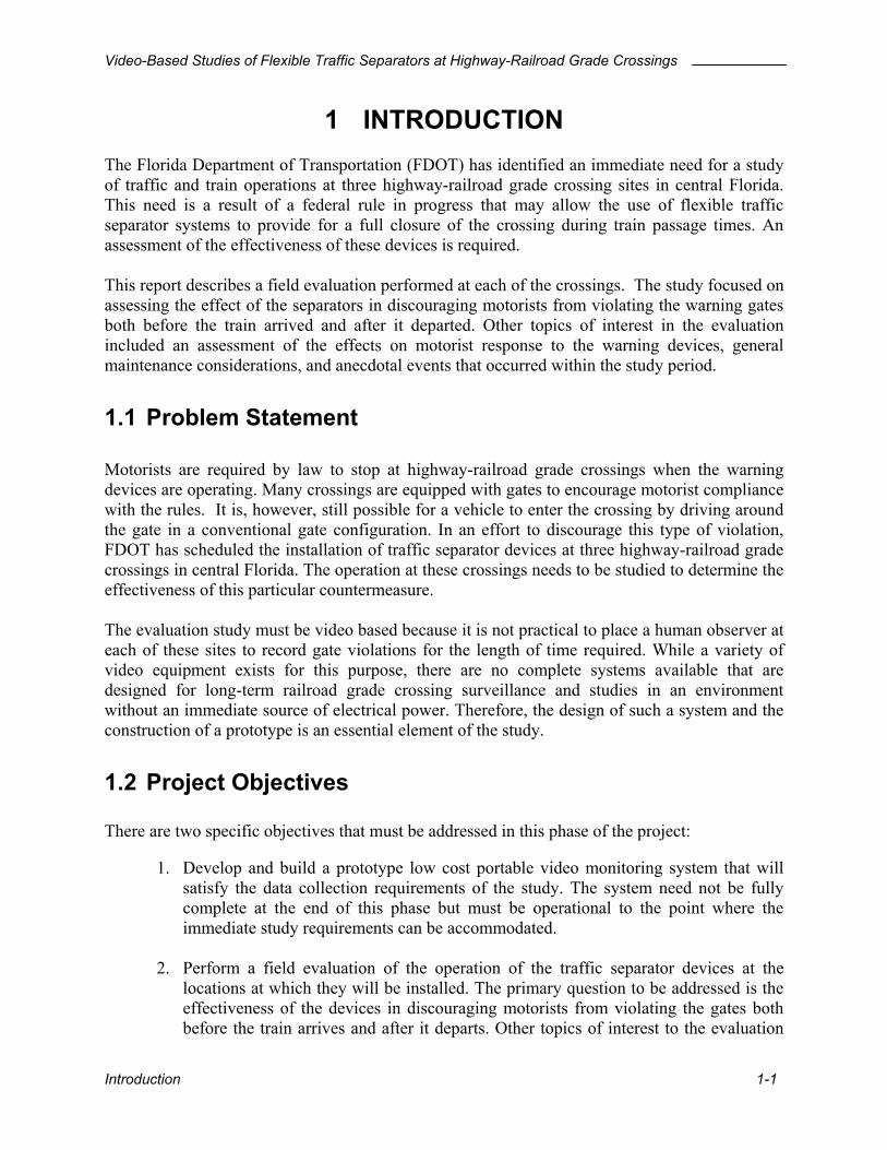
1 INTRODUCTION The Florida Department of Transportation (FDOT) has identified an immediate need for a study of traffic and train operations at three highway-railroad grade crossing sites in central Florida. This need is a result of a federal rule in progress that may allow the use of flexible traffic separator systems to provide for a full closure of the crossing during train passage times. An assessment of the effectiveness of these devices is required. This report describes a field evaluation performed at each of the crossings. The study focused on assessing the effect of the separators in discouraging motorists from violating the warning gates both before the train arrived and after it departed. Other topics of interest in the evaluation included an assessment of the effects on motorist response to the warning devices, general maintenance considerations, and anecdotal events that occurred within the study period.
1.1 Problem Statement Motorists are required by law to stop at highway-railroad grade crossings when the warning devices are operating. Many crossings are equipped with gates to encourage motorist compliance with the rules. It is, however, still possible for a vehicle to enter the crossing by driving around the gate in a conventional gate configuration. In an effort to discourage this type of violation, FDOT has scheduled the installation of traffic separator devices at three highway-railroad grade crossings in central Florida. The operation at these crossings needs to be studied to determine the effectiveness of this particular countermeasure. The evaluation study must be video based because it is not practical to place a human observer at each of these sites to record gate violations for the length of time required. While a variety of video equipment exists for this purpose, there are no complete systems available that are designed for long-term railroad grade crossing surveillance and studies in an environment without an immediate source of electrical power. Therefore, the design of such a system and the construction of a prototype is an essential element of the study.
1.2 Project Objectives There are two specific objectives that must be addressed in this phase of the project:
1. Develop and build a prototype low cost portable video monitoring system that will satisfy the data collection requirements of the study. The system need not be fully complete at the end of this phase but must be operational to the point where the immediate study requirements can be accommodated.
2. Perform a field evaluation of the operation of the traffic separator devices at the
locations at which they will be installed. The primary question to be addressed is the effectiveness of the devices in discouraging motorists from violating the gates both before the train arrives and after it departs. Other topics of interest to the evaluation
Introduction 1-1

Video-Based Studies of Flexible Traffic Separators at Highway-Railroad Grade Crossings
include an assessment of the effects on motorist response to the warning devices, general maintenance considerations, and any anecdotal events that occur within the study period.
1.3 Project Tasks In support of these objectives, the following tasks were performed:
1. The literature was reviewed to identify previous work in the area of data collection, violation and driver behavior categories, before and after study methods, and results of the study. The results of the literature review are presented in Chapter 2
2. A prototype surveillance system was developed for deployment at the three crossing
sites. The components of the system include a set of video cameras with different focal lengths to accommodate various crossing configurations, A telescoping mast for mounting the cameras, a portable 12 volt time-lapse video cassette recorder, a 12 volt marine battery for power and a weatherproof cabinet to house the equipment. Each of these components is described in more detail in Chapter 3.
3. A plan for data collection and analysis was developed. The data collection schedule
was prepared, and the data reduction and analysis methodology was developed. This task is also discussed in Chapter 3
4. A series of “before and after” studies was performed at each of the locations. Three to
four weeks of continuous 24 hr videotapes were produced for each of the study periods. The study details are provided in Chapter 3.
5. The videotaped data were reduced and analyzed by manual observers. The results of
this task are presented in Chapter 4.
6. Based on the results of the data analysis task, a set of conclusions and recommendations was developed, and is presented in Chapter 5. The conclusions suggest that before the traffic separator installation violations were noticeable at two of the three sites, but the violation rates were substantially lower that those reported in the literature from other sites. It was also observed that the warning gate violations dropped to near zero after the traffic separators were installed.
Introduction 1-2

Video-Based Studies of Flexible Traffic Separators at Highway-Railroad Grade Crossings
2 BACKGROUND AND LITERATURE REVIEW
2.1 Before and After Studies Before and after comparisons are typically carried out to demonstrate the effectiveness of technology intended to reduce hazardous events at highway-railroad crossings. The methodology used in before and after studies should be determined by the objectives of the study but may be influenced by practical constraints. The following five research papers were referenced as models to develop appropriate methodologies for this research project. While each paper had its own individual objective, all examined the results of before and after studies:
• Reference 1: “Traffic Violations at Gated Highway-Railroad Grade Crossings” by Texas Transportation Institute (1)
• Reference 2: “Driver Behavior at Vehicle Arresting Barriers” by University of Illinois at Urbana-Champaign (2)
• Reference 3: “Preliminary Evaluation of the School Street Four-Quadrant Gate Highway-Railroad Grade Crossing” by the Volpe National Transportation Systems Center (3)
• Reference 4: “Driver Behavior Study at Rail-Highway Crossing” by Goodell-Grivas (4)
• Reference 5: “A Comparison of Driver Behavior at Railroad Grade Crossings with Two Different Protection Systems” by Ball State University (5)
The characteristics of the five projects above and relationships to this project will be discussed in the following order.
• Objectives of the study • Data collection • Violation categories • Driver behavior categories • Before and after study method • Comparison methods • Results
2.1.1 Objectives of Previous Studies Five papers dealt with five different highway-railroad crossing violation countermeasures. A preliminary study for an enforcement option was performed in reference 1. The effectiveness of the other countermeasures such as a vehicle-arresting barrier (VAB), four-quadrant gates, traffic barriers and barrier gates were estimated in the other four references. Table 2-1 shows the summary of objectives for each project.
Background and Literature Review 2-1

Video-Based Studies of Flexible Traffic Separators at Highway-Railroad Grade Crossings
2.1.2 Data Collection The data collection amounts and methodologies from each project are summarized in . The data amount varied with the objectives of each study. Data collection periods for each of three sites were proposed to assess the effectiveness of QWICK KURB® for this project, assuming one drive-around violation for every ten, gate activations. More detailed discussion will be made about this issue later in Chapter 3. Automatically operated videocassette recorders and Analogue-to-digital video recording systems were used in two projects so that only train events could be recorded and digitized images could be obtained. For this project, a portable video recording system and gate sensor to activate the system were developed for a short-term study and will be explained in Chapter 3.
Table 2-2
Table 2-2: Data Collection Methodology of Previous Projects
Table 2-1: Objectives of Previous Projects
Reference 1 Determine the effects of sending education letters to motorists recorded as violating the gate arms
Reference 2 Compare the driver behaviors in response to VAB system during initial operation period with the ones during intermediate period
Reference 3 Find out the difference between driver behaviors with dual gates and driver behaviors with four-quadrant gates
Reference 4 Test the effectiveness of traffic separators (QWICK KURB®)
Reference 5 Compare flasher only system with the system incorporating flashers and barrier gates
This project Evaluate driver response to traffic separators (QWICK KURB®)
Reference 1 At least 96 hours at each site with mobile video recording systems Reference 2 272 vehicles and 134 trains with analog-to-digital video recording system Reference 3 Total 2297 train movements with analog-to-digital video recording
system Reference 4 272 trains from 37 sites with two manual observers and video camera Reference 5 60 vehicles each for both the before and after barrier installation period
with manual and taped observation This project Total 5,524 vehicles for 3 sites with video surveillance systems
2.1.3 Violation Categories and Driver Behavior Categories Each project contains either violation or driver behavior categories in its contents as shown in Table 2-3. Violation categories depend on the definition of a violation and when the violation occurred. An extensive violation study was performed and will be introduced later in this chapter. The driver behavior category was defined after watching some movements of vehicles at the study sites to make sure that most behaviors can fall into one of the designated categories.
Background and Literature Review 2-2

Video-Based Studies of Flexible Traffic Separators at Highway-Railroad Grade Crossings
One “Stopped and crossed” behavior was recorded in the observation as one “Stopped and waited” and one “Crossed without stopping”, because it was a very rare event at the study site. “Waited from the signal onset” category was added to analyze movements of the stopped vehicles before the warning signal onset, which complied with the traffic signal at the near intersection at the Park Road site.
2.1.4 Before and After Study Methods Table 2-4 presents the before and after study methods used by five different institutes. Violation rates were defined differently in terms of the number of violations per train, per 100 trains and per day in 3 of the references. The concept of violation rates was not applied to this project due to the large variation of the number of train incidents in a day and the number of vehicle crossings per train. For this reason, the total number of violations out of the total number of vehicles that had chance to violate at specific state of active warning devices, was counted for in both the before and after separator installation study period, and compared to each other by the Chi-square test. Bar graphs and line graphs were used to describe the driver behaviors at particular time intervals during different states of active warning devices.
Table 2-3: Violation and Driver Behavior Categories of Each Project
Violation Categories Driver Behavior Categories Reference 1 FL, TEV, AT Reference 2 Crossed without stopping
Stopped and crossed Stopped and waited
Reference 3 Type I, Type II Reference 4 More risky, severe, critical,
risky, routine
Reference 5 Crossed despite warning Stopped and waited
This project Stage I, Stage II, Stage III, Stage IV, Other
Crossed without stopping Stopped and waited Waited from the signal onset
2.1.5 Results No drive-around violations were found after the installation of a four-quadrant gate or traffic separator in reference 3 and 4. Reference 5 indicated the use of traffic separators or four-quadrant gate systems are recommended to prevent possible crashes from happening even though adding a dual gate system to the flashers were effective only in the study. Table 2-5 shows the result summaries of each of the 5 references.
Background and Literature Review 2-3

Video-Based Studies of Flexible Traffic Separators at Highway-Railroad Grade Crossings
Table 2-4: Before and After Separator Installation Study Methods of Each Project
Items compared by the before and after study Comparison method Reference 1 Average number of violations per day Tukey’s test Reference 2 Number of violations and compliances relative
to arrival interval, driver behavior Graphical description % Change in quantity
Reference 3 Number of violations, violations per 100 trains Quantity comparison Reference 4 Average total number of violations per train Chi-Square test Reference 5 Driver behavior, probability of crossing as a
function of train speed Graphical description Chi-Square test
This project Number of violations and compliances relative to arrival interval, driver behavior
Graphical description Chi-Square test
Table 2-5: Result Summaries by Project
Reference 1 Sending educational letters to motorists recorded as violating the gate
arms do not affect the violation rate Reference 2 More violations happened during the intermediate period Reference 3 The four quadrant gate system yielded a decrease in the frequency of type
I violations and 100% reduction in the riskier type II violations Reference 4 Flexible traffic separators are effective in reducing driver violations by
physically restricting motorists from driving around the gates Reference 5 The addition of gates significantly reduced crossing behavior of drivers
from 67% to 38%
2.2 Gate Violation Studies Categorizing the violation types is an essential step in estimating the effectiveness of treatments in reducing violations at highway-railroad crossings. With a basic agreement that a violation occurs if a driver does not comply with active warning devices at highway-railroad crossings, different classifications of violations have been used by several institutions according to the objectives of their studies as shown in Table 2-6.
Background and Literature Review 2-4

Video-Based Studies of Flexible Traffic Separators at Highway-Railroad Grade Crossings
Table 2-6: Definitions of Violation Categories
TTI Definition FL TEV AT
Volpe Definition
Godell-Grivas Definition MRK SV RK
TYPE I
Proposed Definition STAGE I
CRT RT
TYPE II
STAGE II STAGE III STAGE IV( PT )
Flasher OnlyFlasher + Descending Gates
TRAIN PASSAGE
Flasher + Downed Gates
Flasher + Ascending Gates
Warning Devices
Flasher + Downed Gates
Gate Position
There are six phases in an operation of active warning devices that include gates and flashing lights. Before the train arrival, active warning devices are controlled by either constant warning-time or fixed distance warning-time logic. Once activated, flashing lights will remain active throughout each phase identified in Table 2-6. Automatic gates operate in the manner described in Table 2-6. An explanation of the proposed definitions is found in Chapter 3.
2.2.1 Texas Transportation Institute (TTI) The total number of observed violations was divided into three categories by TTI. (1) Flashing light violation (FL) occurs between the time when the flashing lights were initially activated and two seconds after the gate arms began their descent. Typically enforced violation (TEV) period follows FL until train arrival. After train violation (AT) happens in phase IV and V, see Table 2-6. Texas Motor Vehicle law says that a driver commits an offense if the person drives the vehicle around, under, or through a crossing gate or barrier at a railroad crossing while the gate or barrier is closed or being opened. The law does not care about the flasher-only interval violations. In this study the first two seconds at the beginning of gate descent were excluded from TEV as a “grace period” because the study’s objective was to determine the effects of sending education letters to motorists recorded as violating the gate arms for future use of enforcement systems. The grace period allowed for no citation if it was decided that clearing the tracks at the existing speed was safer rather than attempting to stop at a high deceleration rate
Background and Literature Review 2-5

Video-Based Studies of Flexible Traffic Separators at Highway-Railroad Grade Crossings
and risk stopping too close to the tracks. However, the time to clear the tracks at the existing speed will differ substantially from site to site by track clearance time, length of the vehicle, and deceleration ability of the vehicle. Proposed solutions to this problem will be discussed in Chapter 3.
2.2.2 Volpe National Transportation Systems Center The Volpe National Transportation Systems Center study used different classifications for violation study when four-quadrant gate systems were evaluated. During this study, a Type I violation occurs when motor vehicle traversed the grade crossing after the signal onset and before the gates were completely down, and a Type II takes place after the gates were down and before the train arrival. Violations after train departure were not considered in the study. Violations that occur when the gates are still down after the train departs are quite important when multi-track crossings are studied because a train can pass the crossing from the other side of the highway at this point.
2.2.3 Goodell-Grivas The Goodell-Grivas study considered all the vehicles that crossed the crossing during the gate activation phase as violating vehicles. Violations occurring when the gates were down before the train arrival were divided into two parts. Critical violations (CRT) were assumed to occur within 5 seconds before the train arrival. Severe violations (SV) covered the rest of the time. The down-gate time was separated so that the effectiveness of the traffic separator could be estimated by counting the number of drive-around violations. It was found that the crossing actions of vehicles observed before the gates were down are hard to classify as violations according to the definitions given in the literature.
2.3 Gate Violation Countermeasures Several devices have been developed in an attempt to reduce the risky behaviors of drivers at gated highway-railroad crossings. These devices are continually being researched to measure their effectiveness and make improvements.
2.3.1 QWICK KURB® QWICK KURB® deters motorists from driving around cross arms in the down position. The 42” elliptical channelizer creates a visual and psychological deterrent to crossing. The vertical channelizer is a Type 3 Object Marker described in the MUTCD (7). For the marking scheme, “The alternating black and retro reflective yellow stripes (OM-3L, OM-3R) shall be sloped down at an angle of 45 degrees towards the side on which traffic is to pass the obstruction. If traffic can pass to either side of the obstruction, the alternating black and retro reflective yellow stripes (OM-3C) shall form chevrons that point upwards” (Section 3C.02, MUTCD).
Background and Literature Review 2-6

Video-Based Studies of Flexible Traffic Separators at Highway-Railroad Grade Crossings
According to the product literature, QWICK KURB® is “the least expensive safety measure to significantly improve grade crossing safety and the only traffic separator system that has been involved in a FRA sponsored system.” The manufacturer reports that, in one test, the drive-around violations decreased by 75% after the installation of QWICK KURB®.
Figure 2-1: QWICK KURB® Crossing Here are some manufacturer-purported characteristics of QWICK KURB® at highway-railroad crossings:
• Deters drivers from driving around gates • Inexpensive • Quick to install and easy to maintain the system (3 hours of installation time) • Most cost efficient supplemental safety measure available for proposed quiet zones • No activation needed for each train arrival (passive warning devices) • Designed to enable emergency vehicles to cross • Bright reflective surface maintaining high visibility at night • Portable and reusable (made out of recycled rubber and polyethylene) • 5-year warranty against damage from trucks and autos • Additional marker maintenance may be necessary on roadways with a high
percentage of truck traffic where lanes are less than eleven foot in width. Supplemental information of QWICK KURB® can be found in Appendix A.
2.3.2 Four-Quadrant Gates With or Without Median Four-quadrant gate warning systems have been devised to enhance safety at highway-railroad crossings. The use of four gates instead of two provides a “closed” system that secures a crossing and prevents motor vehicles from maneuvering around the deployed gates. A time delay is necessary between the descent of the first set of gates (entrance gates) and the second set of gates
Background and Literature Review 2-7

Video-Based Studies of Flexible Traffic Separators at Highway-Railroad Grade Crossings
(exit gates) to ensure that vehicles do not become trapped. The addition of the obstruction detection system provides the two-fold capability of alerting approaching trains equipped with in-cab signaling devices to the possibility of trapped vehicles, and releasing the exit gates so the trapped vehicles can escape the crossing.
Figure 2-2: Four-Quadrant Gate Railroad Crossing The results of safety assessments in North Carolina’s “Sealed Corridor” project showed that the four-quadrant gate systems were the most effective among the single safety treatments except full closure at highway-railroad grade crossings (5). The four-quadrant systems, combined with traffic separators or automatic train stop systems, are used to maximize safety benefits. Most of the studies were performed at locations with low traffic volumes.
2.3.3 Vehicle Arresting Barrier (VAB) The VAB consists of two separate tower structures containing a fence-style net. When track circuits indicate an approaching train, the nets are lowered simultaneously across the highway to customized energy absorbers. These self-contained spools of steel alloy block the highway approach to a railroad grade crossing. The net has continuous cable running through the top and bottom. The steel tape is wound through a series of offset pins contained in the energy absorber. When a vehicle hits the net assembly, the steel tape is pulled through the pins and out of the energy absorber. The energy required to pull the tape through the pins offsets the energy required to decelerate a vehicle to a controlled stop.
Background and Literature Review 2-8

Video-Based Studies of Flexible Traffic Separators at Highway-Railroad Grade Crossings
Figure 2-3: Vehicle Arresting Barrier at Railroad Crossing Compliance and violation behavior of drivers has been studied during the first year of VAB operation at the McLean site (2). In the research, the following factors were found to affect driver attention to VAB system and possibly mislead driver behavior at highway-railroad crossings:
• Size of the VAB tower • Distance of each VAB tower from a railroad crossing • Location of the active alternating red traffic signals at roadside • Location of alternating red flashing warning lights in the VAB cross bracing above
the roadway.
2.3.4 Photo Enforcement An automated means of gathering photographic or video evidence of violations of traffic laws relating to highway-railroad grade crossings can be an effective supplementary safety measure if there is sufficient support and follow-through by the law enforcement and judicial community. The state of Florida does not have legislation to permit the use of photo enforcement to issue citations at highway-railroad crossings, but local law enforcement agencies can enact local ordinances permitting the issuance of citations. The photo-based video enforcement methods combined with a fine/penalty structure were proven to be an effective alternative to traditional enforcement by the recent safety assessment project in North Carolina’s “Sealed Corridor” Project (6).
Background and Literature Review 2-9

Video-Based Studies of Flexible Traffic Separators at Highway-Railroad Grade Crossings
2.3.5 Some Intelligent Technologies There are some intelligent transportation systems used or being tested to reduce possible crashes or delays at highway-railroad grade crossings (10). They are, for the most part, operated by vehicle or train detection systems. Variable Message Signs The intelligent grade crossing allows nearby variable message signs to display messages that inform drivers of current conditions at the crossing. Messages displayed include “Train Approaching”, “Crossing Delay”, “Exit Lane Blocked” and “Train in Station”.
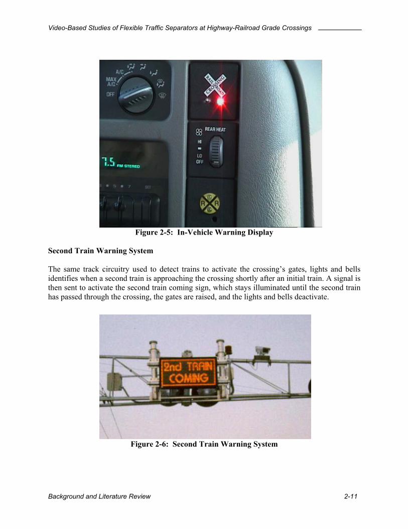
Figure 2-4: Variable Message Sign Board In-Vehicle Warning Systems The system uses wireless vehicle and roadside communication antennas built into the familiar crossbuck sign and front vehicle license plate. The trackside unit picks up a signal from the railroad’s train detection electronics and transmits that signal to the antenna-signs. The in-vehicle display alerts drivers using both visual and audible signals.
Background and Literature Review 2-10
Video-Based Studies of Flexible Traffic Separators at Highway-Railroad Grade Crossings
Figure 2-5: In-Vehicle Warning Display Second Train Warning System The same track circuitry used to detect trains to activate the crossing’s gates, lights and bells identifies when a second train is approaching the crossing shortly after an initial train. A signal is then sent to activate the second train coming sign, which stays illuminated until the second train has passed through the crossing, the gates are raised, and the lights and bells deactivate.
Figure 2-6: Second Train Warning System
Background and Literature Review 2-11

Video-Based Studies of Flexible Traffic Separators at Highway-Railroad Grade Crossings
Four-Quadrant Gate with Automatic Train Stop A system of four gates is used rather than the usual two, to prevent waiting vehicles from starting to cross the tracks and thus running the gate. Six inductive loop sensors, embedded within the crossing, are used to detect the presence of a vehicle or other obstacle that is blocking the crossing. The interface with the Amtrak in-cab signaling system provides the locomotive engineer with a notice to stop the train safely before it reaches the crossing. If the engineer fails to reduce the train’s speed, the in-cab signaling system will stop the train automatically.
Figure 2-7: Four-Quadrant Gate with Automatic Train Stop
Background and Literature Review 2-12
Video-Based Studies of Flexible Traffic Separators at Highway-Railroad Grade Crossings
3 RESEARCH METHODOLOGY
3.1 Site Description
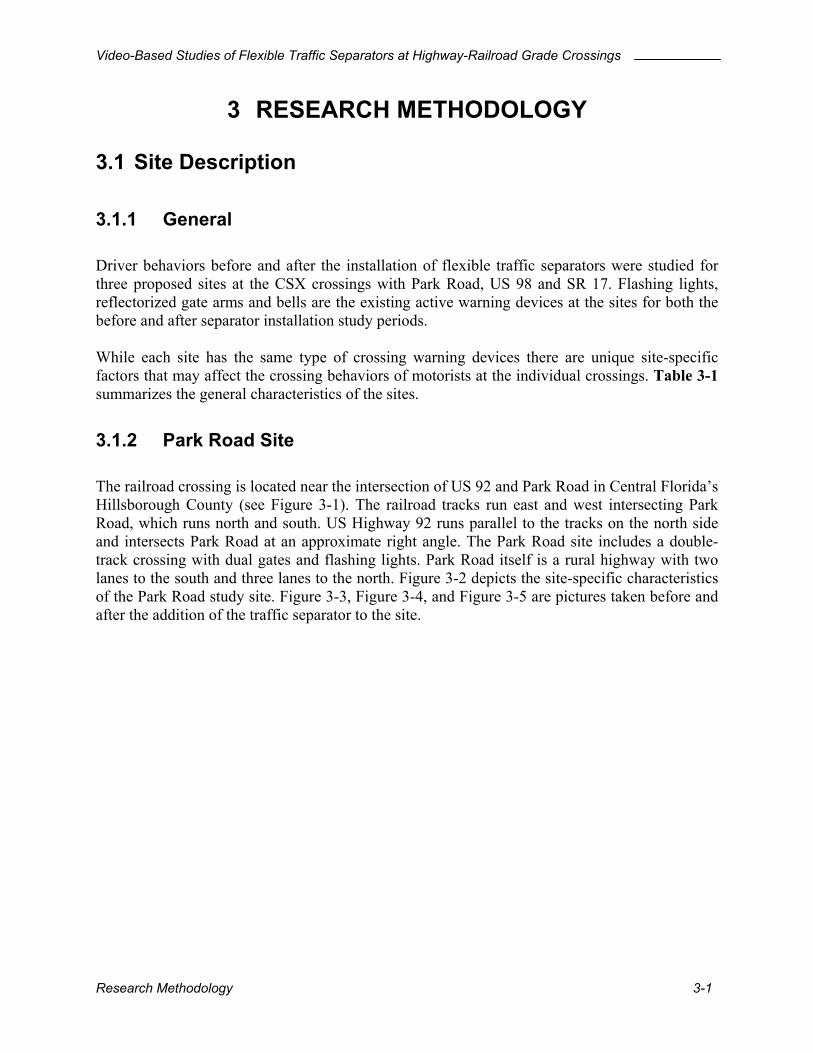
3.1.1 General Driver behaviors before and after the installation of flexible traffic separators were studied for three proposed sites at the CSX crossings with Park Road, US 98 and SR 17. Flashing lights, reflectorized gate arms and bells are the existing active warning devices at the sites for both the before and after separator installation study periods. While each site has the same type of crossing warning devices there are unique site-specific factors that may affect the crossing behaviors of motorists at the individual crossings. summarizes the general characteristics of the sites.
Table 3-1
3.1.2 Park Road Site The railroad crossing is located near the intersection of US 92 and Park Road in Central Florida’s Hillsborough County (see Figure 3-1). The railroad tracks run east and west intersecting Park Road, which runs north and south. US Highway 92 runs parallel to the tracks on the north side and intersects Park Road at an approximate right angle. The Park Road site includes a double-track crossing with dual gates and flashing lights. Park Road itself is a rural highway with two lanes to the south and three lanes to the north. depicts the site-specific characteristics of the Park Road study site. , , and are pictures taken before and after the addition of the traffic separator to the site.
Figure 3-2Figure 3-3 Figure 3-4 Figure 3-5
Research Methodology 3-1

Video-Based Studies of Flexible Traffic Separators at Highway-Railroad Grade Crossings
Table 3-1: Site Characteristics Park Road Site US 98 Site SR 17 Site FDOT District 7 1 1 County Hillsborough Polk Polk Roadway Jurisdiction County State
State Highway South Park Road or
County Road 553 US 98 or SR 700 SR 17 (Alt US 27)
Lanes 5 (3 for NB, 2 for SB)
2 2
Posted Roadway Speed
45 55 55
AADT 16,100 3,854 2,592 Railroad CSX Transportation CSX Transportation CSX Transportation Trains per day 19 16 10 Tracks 2
(1 Main, 1 other) 1 1
Train Speed 55 ~ 60 74 ~ 79 74 ~ 79 Trains per day 19 16 10 Crossing Number 624313P 627561Y 627563M
Crossing Type Public at grade Public at grade Public at grade
Safety Rating 224 885 615
Train Activated Warning Devices
2 R/W Reflectorized Gates,
2 Mast Mounted FL, 2 Cantilevered FL
(over), 2 Bells
2 R/W Reflectorized Gates,
2 Mast Mounted FL, 1 other FL,
1 Bell
2 R/W Reflectorized Gates,
2 Mast Mounted FL, 2 Cantilevered FL
(over), 1 Bell
Warning Time Type Constant Angle of Intersection
90 degrees 50 degrees 70 degrees
Type of Preemption Simultaneous
Track Clearance Distance
64.8 ft (NB) 47.8 ft (SB)
31.0 ft 30.3 ft
Research Methodology 3-2

Video-Based Studies of Flexible Traffic Separators at Highway-Railroad Grade Crossings
Figure 3-1: Map of the Park Road Site
Clear Storage Distance
( 14ft )
Track Clearance Distance
( 64.8ft )
39ft5.3ft5.3ft
9.2ft
N S
RA
ILR
OA
D T
RA
CK
RA
ILR
OA
D T
RA
CK
PARK ROAD
US92
STO
P H
ERE
ON
R
ED
DO
NO
T ST
OP
ON
TR
AC
KS
RAIL
ROADCROSSING
TRA
CK
S2
RIGHT LANE MUST
TURN RIGHT
R.R. Flashing Light Signals & Automatic Gate
Portable railroad crossing video surveillance system installed on an existing utility pole
196.9ft (60m) of median separator system( 30 rebundable markers installed on separator ,with 6.6 ft (2m)-spacing, and 3.3ft (1m)-height each )
Figure 3-2: Park Road Site Geometry
Research Methodology 3-3

Video-Based Studies of Flexible Traffic Separators at Highway-Railroad Grade Crossings
A flexible traffic separator was installed on the south side of the tracks. No separator was installed on the southbound approach because southbound vehicles have no chance to drive around the gates without stopping. The restriction results from simultaneous traffic-signal preemption that causes the queue clearance-time to begin a few seconds before the gates are in a horizontal position. A smaller number of northbound drive-around violations were anticipated at this crossing compared with a crossing without an intersection in close proximity. This assumption takes into consideration the trajectories of a vehicle driving around the gates. Left-turning vehicles in the left-turn only lane would make a zigzag pattern in order to drive around the gates while through and right-turning vehicles would, by necessity have to make a wide turn through the left-turn only lane. Once the violation has occurred, the resultant situation is more critical. Stopping on the tracks is the other possibly perilous driver behavior at the Park Road site. This behavior could occur due to the short, clear-storage distance (14 feet) that does not allow enough space for the queue build-up from the near intersection. Crash Data
Crash and inventory data were found in the Federal Railroad Administration (FRA) website database. Nine crashes occurred from early 1976 until August of 1985, the time when the automatic gates were installed. The majority of these crashes occurred because the vehicles did not stop. Two crashes took place after the installation of the gates. Both of these crashes involved truck trailers heading south during the daytime hours. One truck drove around the gates and the other stopped on the tracks at the time of violation.
Research Methodology 3-4

Video-Based Studies of Flexible Traffic Separators at Highway-Railroad Grade Crossings
Figure 3-3: Park Road Site from the South (Before Separator Installation)
Figure 3-4: Park Road Site from the South (After Separator Installation)
Research Methodology 3-5
Video-Based Studies of Flexible Traffic Separators at Highway-Railroad Grade Crossings
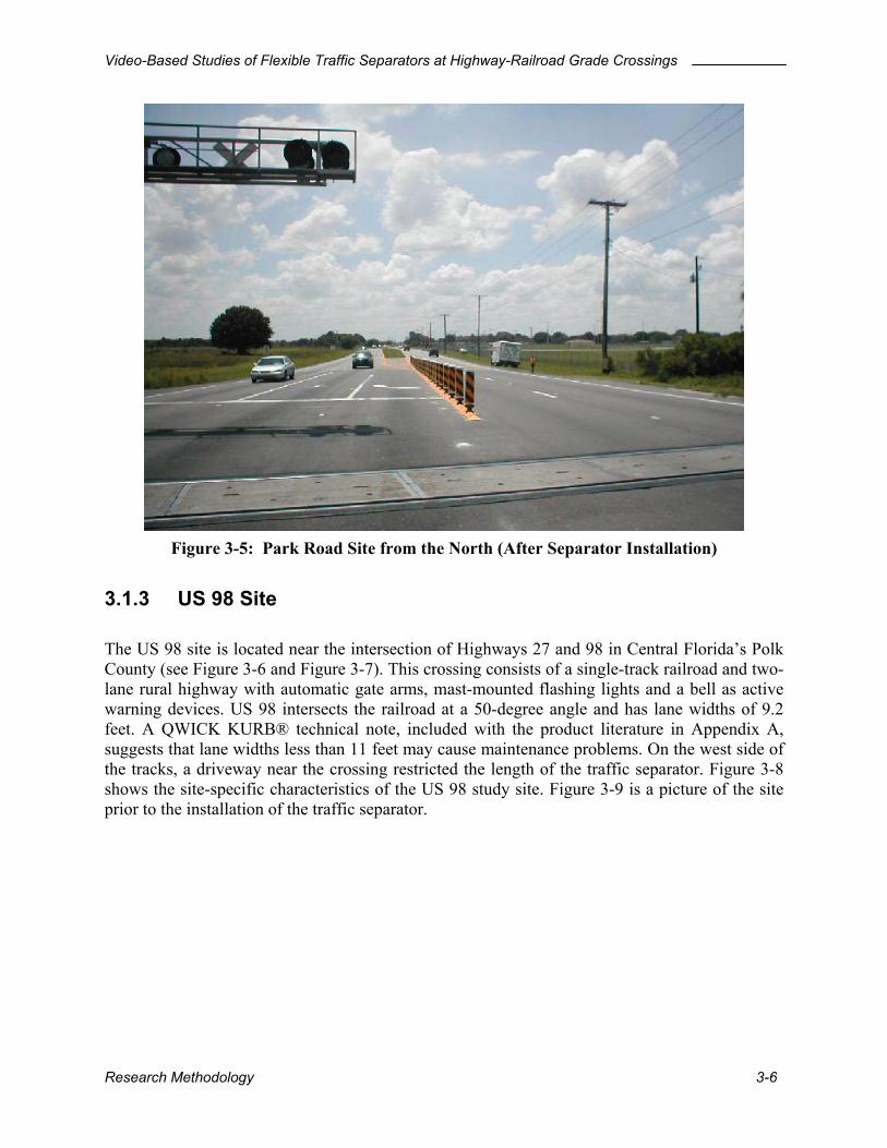
Figure 3-5: Park Road Site from the North (After Separator Installation)
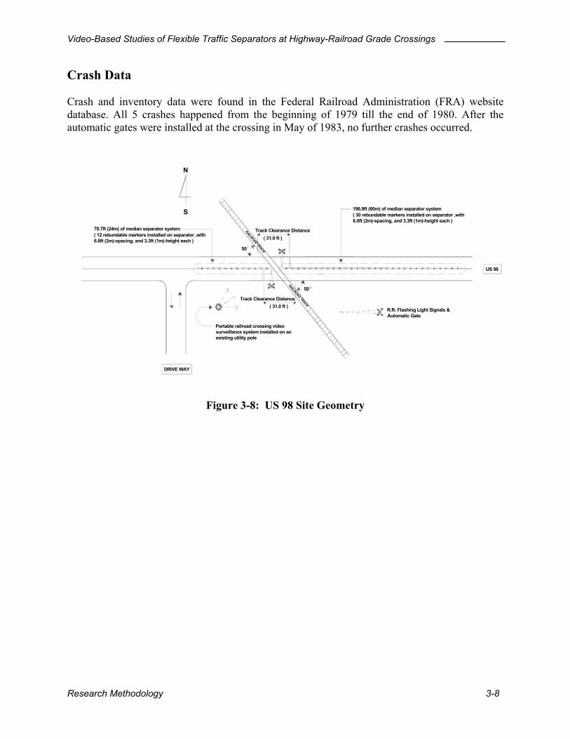
3.1.3 US 98 Site The US 98 site is located near the intersection of Highways 27 and 98 in Central Florida’s Polk County (see and ). This crossing consists of a single-track railroad and two-lane rural highway with automatic gate arms, mast-mounted flashing lights and a bell as active warning devices. US 98 intersects the railroad at a 50-degree angle and has lane widths of 9.2 feet. A QWICK KURB® technical note, included with the product literature in Appendix A, suggests that lane widths less than 11 feet may cause maintenance problems. On the west side of the tracks, a driveway near the crossing restricted the length of the traffic separator. Figure 3-8 shows the site-specific characteristics of the US 98 study site. Figure 3-9 is a picture of the site prior to the installation of the traffic separator.
Figure 3-6 Figure 3-7
Research Methodology 3-6

Video-Based Studies of Flexible Traffic Separators at Highway-Railroad Grade Crossings
Research
X
Figure 3-6: Map 1 of the US 98 Site
X
Figure 3-7: Map 2 of the US 98 Site
Methodology 3-7
Video-Based Studies of Flexible Traffic Separators at Highway-Railroad Grade Crossings
Crash Data Crash and inventory data were found in the Federal Railroad Administration (FRA) website database. All 5 crashes happened from the beginning of 1979 till the end of 1980. After the automatic gates were installed at the crossing in May of 1983, no further crashes occurred.
Track Clearance Distance( 31.0 ft )
( 31.0 ft ) Track Clearance Distance
Portable railroad crossing video surveillance system installed on an existing utility pole
DRIVE WAY
S
RAILROAD TRACK50
N
US 98
R.R. Flashing Light Signals & Automatic Gate
RAILROAD TRACK
50
( 30 rebundable markers installed on separator ,with 6.6ft (2m)-spacing, and 3.3ft (1m)-height each )
196.9ft (60m) of median separator system
( 12 rebundable markers installed on separator ,with 6.6ft (2m)-spacing, and 3.3ft (1m)-height each )
78.7ft (24m) of median separator system
Figure 3-8: US 98 Site Geometry
Research Methodology 3-8
Video-Based Studies of Flexible Traffic Separators at Highway-Railroad Grade Crossings
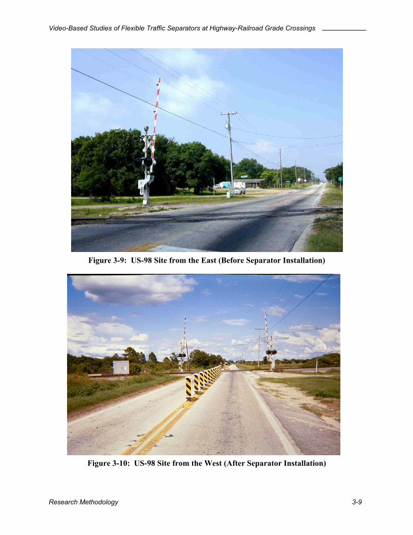
Figure 3-9: US-98 Site from the East (Before Separator Installation)
Figure 3-10: US-98 Site from the West (After Separator Installation)
Research Methodology 3-9
Video-Based Studies of Flexible Traffic Separators at Highway-Railroad Grade Crossings
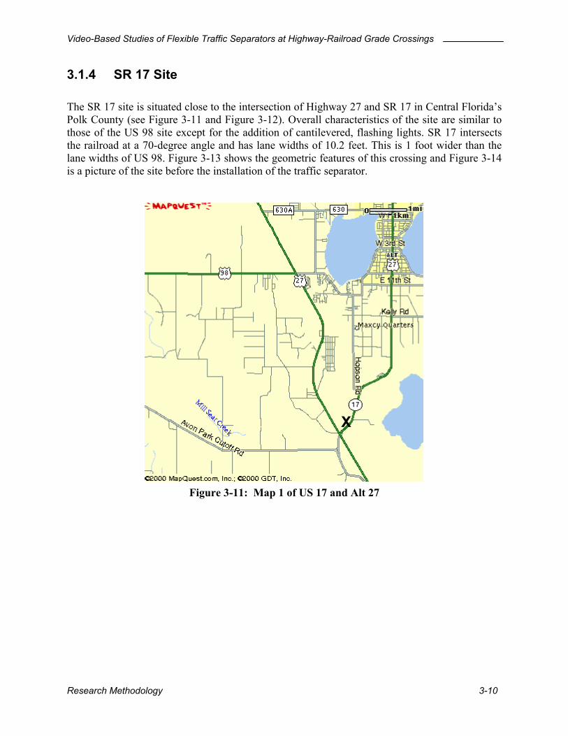
3.1.4 SR 17 Site The SR 17 site is situated close to the intersection of Highway 27 and SR 17 in Central Florida’s Polk County (see and ). Overall characteristics of the site are similar to those of the US 98 site except for the addition of cantilevered, flashing lights. SR 17 intersects the railroad at a 70-degree angle and has lane widths of 10.2 feet. This is 1 foot wider than the lane widths of US 98. shows the geometric features of this crossing and is a picture of the site before the installation of the traffic separator.
Figure 3-11
Figure 3-11: Map 1 of US 17 and Alt 27
Figure 3-12
Figure 3-13 Figure 3-14
X
Research Methodology 3-10

Video-Based Studies of Flexible Traffic Separators at Highway-Railroad Grade Crossings
Figure 3-12: Map Crash Data Only one crash has been found in the Federasince the automatic gates were installed at passenger car stopped on the crossing tracks. injury was recorded for the driver and around
Research Methodology
X
2 of US 17 and Alt 27
l Railroad Administration (FRA) website database the crossing. On May 15, 1995 at 9:05 PM, a The vehicle was struck by railroad equipment. No $800 of vehicle property damage was reported.
3-11

Video-Based Studies of Flexible Traffic Separators at Highway-Railroad Grade Crossings
Track Clearance Distance
( 30.3 ft ) Track Clearance Distance
RAIL
TRA
CK
Portable railroad crossing video surveillance system installed on an existing utility pole ( 30.3 ft )
SR 17
R.R. Flashing Light Signals & Automatic Gate
70
S
N
( 30 rebundable markers installed on separator ,with 6.6ft (2m)-spacing, and 3.3ft (1m)-height each )
( 30 rebundable markers installed on separator ,with 6.6ft (2m)-spacing, and 3.3ft (1m)-height each )
196.9ft (60m) of median separator system196.9ft (60m) of median separator system
Figure 3-13: SR 17 Site Geometry
Figure 3-14: SR 17 Site from the Southwest (Before Separator Installation)
Research Methodology 3-12
Video-Based Studies of Flexible Traffic Separators at Highway-Railroad Grade Crossings
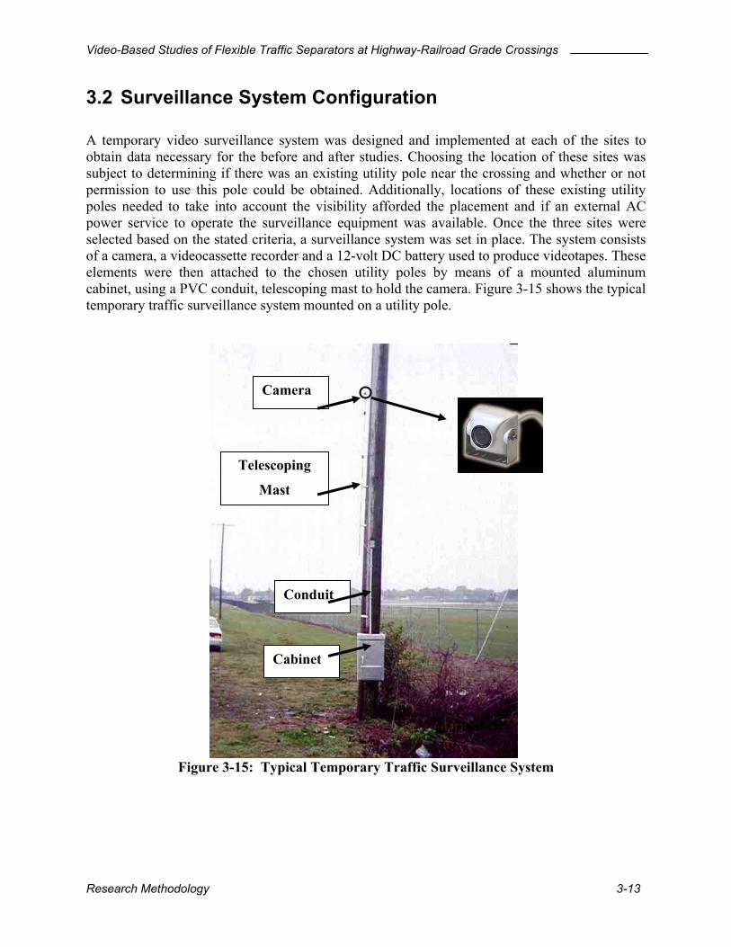
3.2 Surveillance System Configuration A temporary video surveillance system was designed and implemented at each of the sites to obtain data necessary for the before and after studies. Choosing the location of these sites was subject to determining if there was an existing utility pole near the crossing and whether or not permission to use this pole could be obtained. Additionally, locations of these existing utility poles needed to take into account the visibility afforded the placement and if an external AC power service to operate the surveillance equipment was available. Once the three sites were selected based on the stated criteria, a surveillance system was set in place. The system consists of a camera, a videocassette recorder and a 12-volt DC battery used to produce videotapes. These elements were then attached to the chosen utility poles by means of a mounted aluminum cabinet, using a PVC conduit, telescoping mast to hold the camera. Figure 3-15 shows the typical temporary traffic surveillance system mounted on a utility pole.
Camera
Telescoping
Mast
Conduit
Cabinet
Figure 3-15: Typical Temporary Traffic Surveillance System
Research Methodology 3-13
Video-Based Studies of Flexible Traffic Separators at Highway-Railroad Grade Crossings
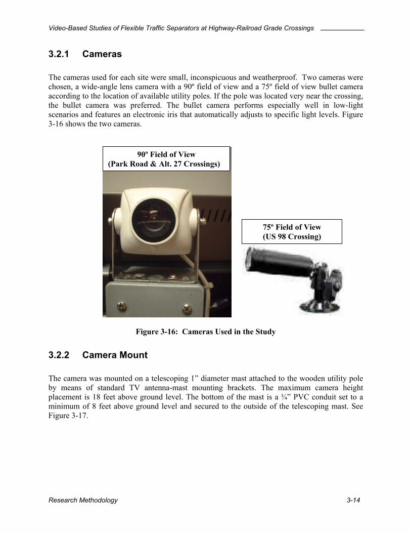
3.2.1 Cameras The cameras used for each site were small, inconspicuous and weatherproof. Two cameras were chosen, a wide-angle lens camera with a 90º field of view and a 75º field of view bullet camera according to the location of available utility poles. If the pole was located very near the crossing, the bullet camera was preferred. The bullet camera performs especially well in low-light scenarios and features an electronic iris that automatically adjusts to specific light levels.
shows the two cameras. Figure
3-16
Figure 3-16: Cameras Used in the Study
90º Field of View (Park Road & Alt. 27 Crossings)
75º Field of View (US 98 Crossing)
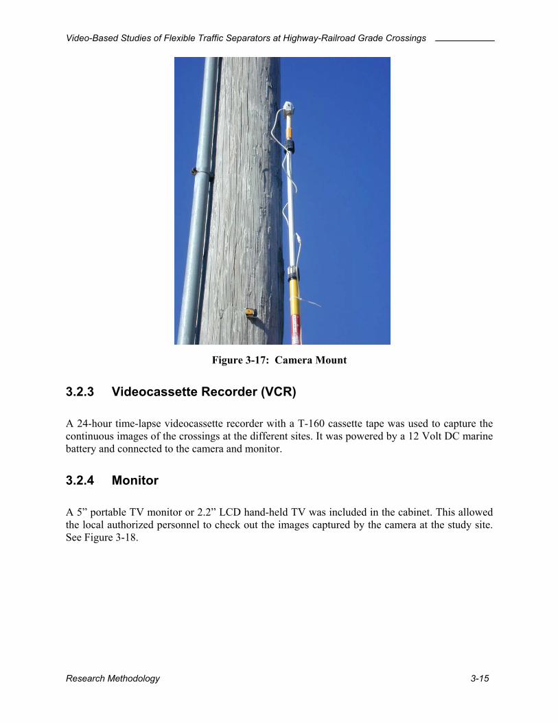
3.2.2 Camera Mount The camera was mounted on a telescoping 1” diameter mast attached to the wooden utility pole by means of standard TV antenna-mast mounting brackets. The maximum camera height placement is 18 feet above ground level. The bottom of the mast is a ¾” PVC conduit set to a minimum of 8 feet above ground level and secured to the outside of the telescoping mast. See
. Figure 3-17
Research Methodology 3-14
Video-Based Studies of Flexible Traffic Separators at Highway-Railroad Grade Crossings
Figure 3-17: Camera Mount
3.2.3 Videocassette Recorder (VCR) A 24-hour time-lapse videocassette recorder with a T-160 cassette tape was used to capture the continuous images of the crossings at the different sites. It was powered by a 12 Volt DC marine battery and connected to the camera and monitor.
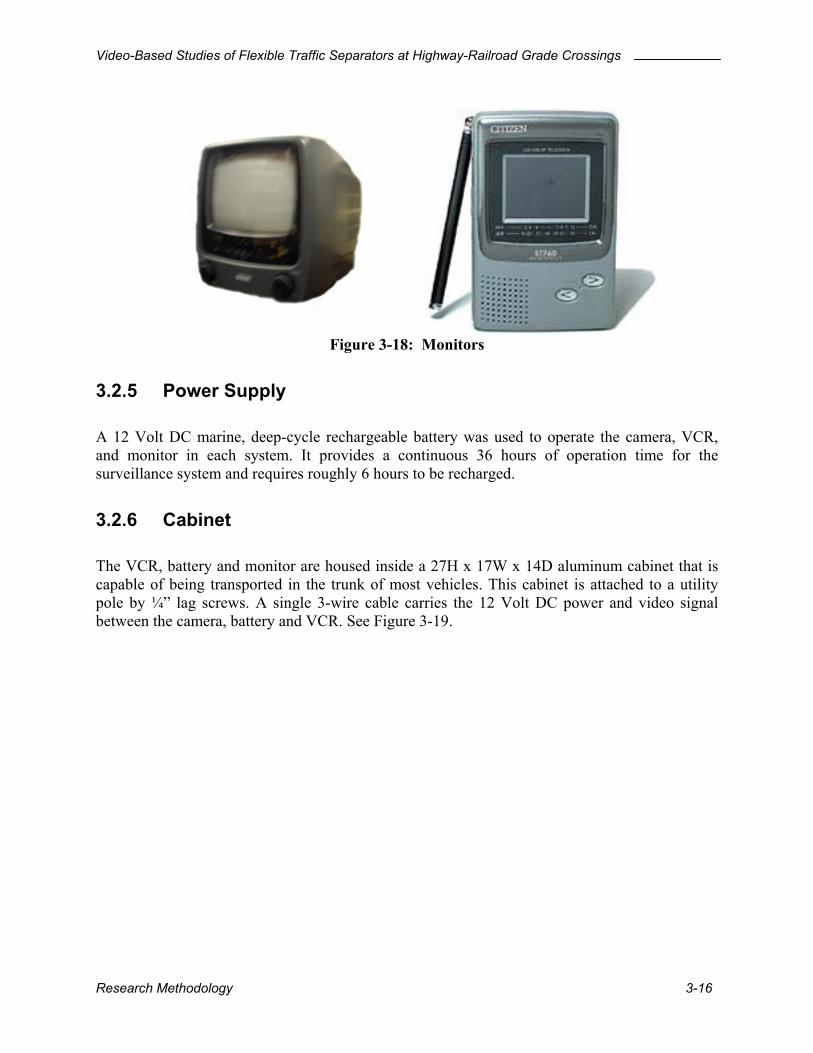
3.2.4 Monitor A 5” portable TV monitor or 2.2” LCD hand-held TV was included in the cabinet. This allowed the local authorized personnel to check out the images captured by the camera at the study site. See Figure 3-18.
Research Methodology 3-15
Video-Based Studies of Flexible Traffic Separators at Highway-Railroad Grade Crossings
Figure 3-18: Monitors
3.2.5 Power Supply A 12 Volt DC marine, deep-cycle rechargeable battery was used to operate the camera, VCR, and monitor in each system. It provides a continuous 36 hours of operation time for the surveillance system and requires roughly 6 hours to be recharged.
3.2.6 Cabinet The VCR, battery and monitor are housed inside a 27H x 17W x 14D aluminum cabinet that is capable of being transported in the trunk of most vehicles. This cabinet is attached to a utility pole by ¼” lag screws. A single 3-wire cable carries the 12 Volt DC power and video signal between the camera, battery and VCR. See Figure 3-19.
Research Methodology 3-16

Video-Based Studies of Flexible Traffic Separators at Highway-Railroad Grade Crossings
Figure 3-19: Mounted Cabinet
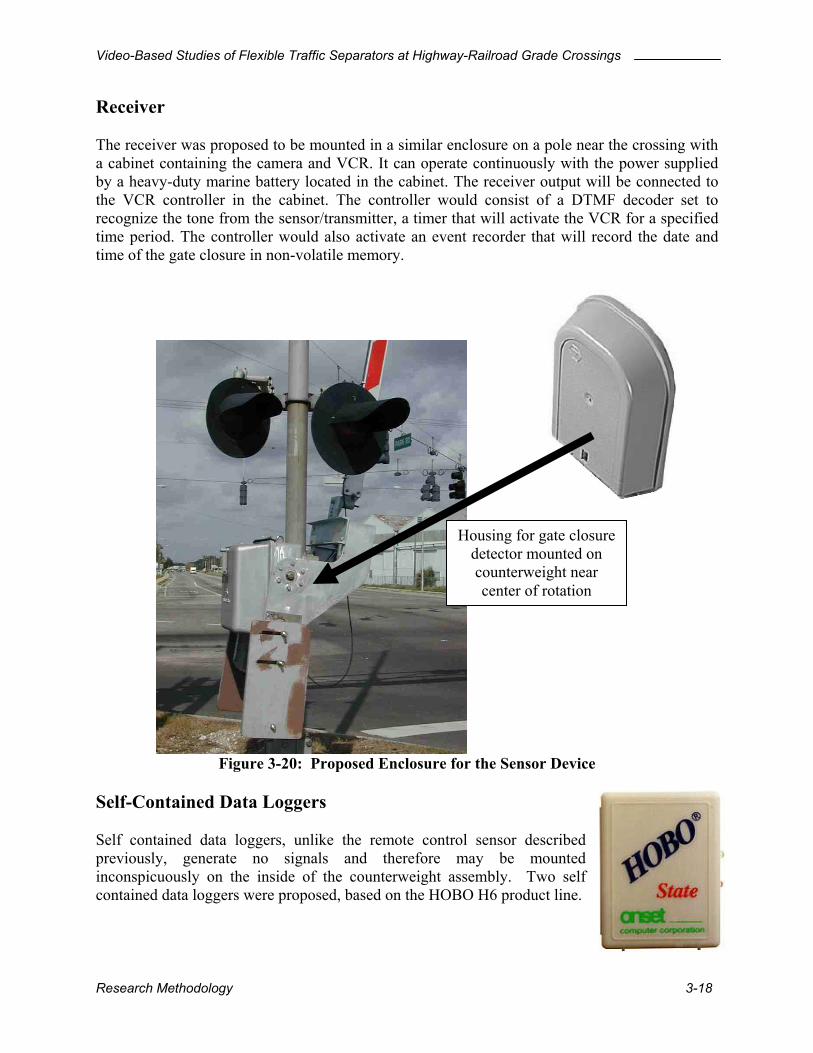
3.2.7 Gate Closure Sensor The use of a gate-closure sensor was considered to provide a radio frequency signal to a receiver that would activate the VCR that was connected to a surveillance camera in the vicinity of crossing. Activation of the VCR by the gate closure is an essential element in the design of a productive study. Without such activation, it would be necessary to videotape the operation of the crossing continuously for the entire duration of the study. None of the instrumentation described in this section was installed. It is described here to provide a complete description of the project activities Transmitter It was proposed that an enclosure containing the sensor device be mounted on the counterweight for the gate arm as illustrated in . The enclosure dimensions are approximately 6.5H x 5.25W x 1.75D. The sensor configuration consists of a mercury switch that detects the movement of the gate, an FCC-approved transmitter (560 MHz FRS band), a DTMF tone generator, and a timer to limit the duration of the tone in compliance with FCC requirements. Standard alkaline batteries installed in the enclosure supply power to all of the electronic devices. The enclosure itself is designed for outdoor use in cable and telephone applications (Radio Shack Part # 270-258). It is approximately the same metallic color as the counterweight and will present an inconspicuous appearance. It will not interfere in any way with the operation of the crossing warning devices. If necessary, a label to identify the device for railroad maintenance personnel can be attached to the enclosure.
Figure 3-20
Research Methodology 3-17
Video-Based Studies of Flexible Traffic Separators at Highway-Railroad Grade Crossings
Receiver The receiver was proposed to be mounted in a similar enclosure on a pole near the crossing with a cabinet containing the camera and VCR. It can operate continuously with the power supplied by a heavy-duty marine battery located in the cabinet. The receiver output will be connected to the VCR controller in the cabinet. The controller would consist of a DTMF decoder set to recognize the tone from the sensor/transmitter, a timer that will activate the VCR for a specified time period. The controller would also activate an event recorder that will record the date and time of the gate closure in non-volatile memory.
Housing for gate closure detector mounted on counterweight near center of rotation
Figure 3-20: Proposed Enclosure for the Sensor Device Self-Contained Data Loggers Self contained data loggers, unlike the remote control sensor described previously, generate no signals and therefore may be mounted inconspicuously on the inside of the counterweight assembly. Two self contained data loggers were proposed, based on the HOBO H6 product line.
Research Methodology 3-18

Video-Based Studies of Flexible Traffic Separators at Highway-Railroad Grade Crossings
1. Gate Closure Logger The gate-closure logger (GCL) uses a mercury switch to provide switch closure states to a HOBO H6 state logger (See Appendix A for specifications). The logger records the date and time (at 0.5 sec resolution) each time the gate opens and closes. There are two applications for the GCL:
• Facilitate videotape observation studies by providing a list of times for gate-closure events. This application offers significant benefits for traffic studies which otherwise would require the viewing of the complete videotapes to determine when the events occurred. The benefits would be greatest at crossings with low train volumes.
• Stand alone operation to simply produce a record of gate operation times and durations for traffic study purposes.
2. Gate Violation Logger The gate violation logger (GVL) has the same features as the GCL, but uses a pneumatic road-tube switch to provide inputs to a HOBO H6 event logger. The event logger differs from the data logger in that it responds to switch closures only, and ignores the return to the “open” state. The road tube was positioned in such a manner that all vehicles crossing the tracks would activate it. So, in combination with the mercury switch, the GVL will provide a list of times during which gate violations occurred. Studies will be performed using videotape to determine the validity of the data produced by the GVL. If it is determined that the GVL produces data that are sufficiently accurate, it may be possible to replace videotape studies in the future by GVL studies, which involve considerably lower effort and expense.
3.3 Data collection Data were collected using the video surveillance system installed on a utility pole near each crossing. The authorized local personnel changed the batteries and videotapes regularly. All the recorded videotapes were sent to the Transportation Research Center laboratory at the University of Florida to be analyzed. The gate-closure sensors and data loggers were not implemented at any of the field locations because the railroad would not permit the attachment of these devices to their gates.
3.3.1 Schedule The required sampling intervals at each site were estimated as following for both the before and after studies: 3 weeks for Park Road site; 4 weeks for US 98 site and 6 weeks for SR 17 site. These estimates were based on the assumption that one incident occurs for every 10 activations. For a conservative test, which is based on a Chi-Square distribution of incidents, with a target of
Research Methodology 3-19

Video-Based Studies of Flexible Traffic Separators at Highway-Railroad Grade Crossings
50 percent reduction to be significant, the capture of 30 incidents or 300 activations will be required. For the determination of the plastic traffic separator system effectiveness, an incident is considered to occur whenever a vehicle drives around the gates from the time that the gates are activated and until the gates are returned to their upright position. The sampling interval for the before study at the Park Road site was extend to 6 weeks while the period at the other two sites remained the same considering the number of activations. Only 2 incidents with more than 300 activations were observed at the Park Road site for the first 3 weeks. Table 3-2 presents a summary of the data gathered from each study site.
Table 3-2: Data Collection Summary
Park Road US 98 SR 17 Before After Before After Before After Sampling Interval
02/07/02 ~03/20/02
04/16/02 ~05/08/02
05/15/02 ~06/16/02
6/28/02 ~7/21/02
05/14/02 06/17/02
6/27/02 7/21/02
Average trains a day (Weekdays)
7.9 10.5 15.2 12.2 15.5 15.1
Average trains a day (Weekends)
19.4 21.1 12.9 13.3 12.5 14.0
Total vehicles observed
2562
1887 614 324 461 293
Total gate activations 657 410 450 328 540 403 Total trains 649 410 450 327 482 383 QWICK KURB® installation date
04/16/02
06/27/02
06/27/02
3.3.2 Videotape Library One tape per day was produced by the surveillance system from each crossing. In the period before the separators were installed, a total of 41, 31 and 33 tapes was obtained at Park Road US 98 and SR 17, respectively. In the period after the separators were installed the corresponding totals were 20, 22, and 26 tapes Each of these tapes was labeled by the name of the site (PRK01, PRK02, US9801, SR1701, etc.). Another series of compressed tapes containing only the activations of the warning devices was created to expedite the data reduction process A complete summary of the videotape data collection activities is presented at the end of this chapter.
Research Methodology 3-20
Video-Based Studies of Flexible Traffic Separators at Highway-Railroad Grade Crossings
3.4 Data Reduction and Analysis
3.4.1 Manual Observations Three observers viewing the compressed videotapes of the sites using a color monitor and videocassette recorder accomplished the data acquisition effort. Each of the observers was assigned the tapes from one site to view, considering site-specific situations during the before and after study. The following activities were recorded to aid in the visualization of the occurrences happening at the crossings with the time stamp present on each video.
• Tape number and date • Facility type (before or after the installation of QWICK KURB®) • Gate activation number within a tape • Signal onset (time when the flashing lights began) • Vehicle action (queued part of signal, stopped voluntarily, crossed) • Position of stopped vehicle • Time at which the vehicle crossed the railroad (time of violation occurrence) • Stages at which the vehicle could have violated • Stage at which the vehicle actually violated • Time at which the vehicle could have crossed the railroad assuming it had maintained
its approaching speed (time of vehicle arrival) • Whether the vehicle started proceeding or did not stop when it crossed the railroad. • Vehicle types • Train existence at each gate activation • Train arrival • Train departure • Train speed (fast, slow) • Movement of the train (passed, stopped near the crossing) • Directions of the vehicle and train • Time gates were returned to their upright position
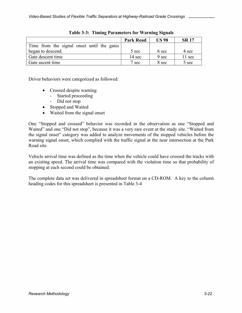
Recording Method Every vehicle that either crossed the crossing or could have crossed during the activation of the active warning devices has been recorded. Military time on the time stamp was used to facilitate the recording and relieve the confusion caused by distinction of AM and PM classification. The site-specific timing parameters for each crossing were observed and are presented in Table 3-3. These parameters indicate when the gates began to descend and ascend, calculated from the time of signal onset to the time when the gates were returned to their upright position.
Research Methodology 3-21
Video-Based Studies of Flexible Traffic Separators at Highway-Railroad Grade Crossings
Table 3-3: Timing Parameters for Warning Signals
Park Road US 98 SR 17 Time from the signal onset until the gates began to descend.
5 sec
6 sec
4 sec
Gate descent time 14 sec 9 sec 11 sec Gate ascent time 7 sec 8 sec 5 sec
Driver behaviors were categorized as followed:
• Crossed despite warning - Started proceeding - Did not stop
• Stopped and Waited • Waited from the signal onset
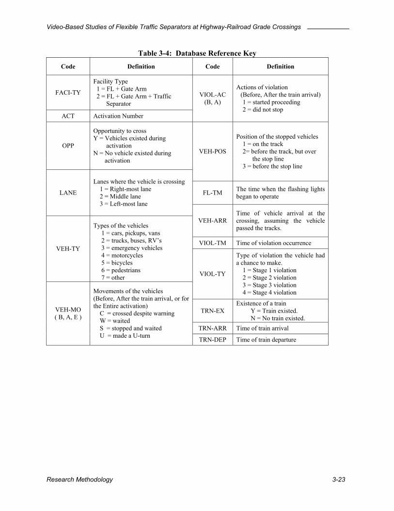
One “Stopped and crossed” behavior was recorded in the observation as one “Stopped and Waited” and one “Did not stop”, because it was a very rare event at the study site. “Waited from the signal onset” category was added to analyze movements of the stopped vehicles before the warning signal onset, which complied with the traffic signal at the near intersection at the Park Road site. Vehicle arrival time was defined as the time when the vehicle could have crossed the tracks with an existing speed. The arrival time was compared with the violation time so that probability of stopping at each second could be obtained. The complete data set was delivered in spreadsheet format on a CD-ROM. A key to the column heading codes for this spreadsheet is presented in Table 3-4
Research Methodology 3-22
Video-Based Studies of Flexible Traffic Separators at Highway-Railroad Grade Crossings
Table 3-4: Database Reference Key
Code Definition Code Definition
FACI-TY
Facility Type 1 = FL + Gate Arm 2 = FL + Gate Arm + Traffic Separator
ACT Activation Number
VIOL-AC (B, A)
Actions of violation (Before, After the train arrival)
1 = started proceeding 2 = did not stop
OPP
Opportunity to cross Y = Vehicles existed during activation N = No vehicle existed during activation
VEH-POS
Position of the stopped vehicles 1 = on the track 2= before the track, but over the stop line 3 = before the stop line
FL-TM The time when the flashing lights began to operate LANE
Lanes where the vehicle is crossing 1 = Right-most lane 2 = Middle lane 3 = Left-most lane
VEH-ARR Time of vehicle arrival at the crossing, assuming the vehicle passed the tracks.
VIOL-TM Time of violation occurrence VEH-TY
Types of the vehicles 1 = cars, pickups, vans 2 = trucks, buses, RV’s 3 = emergency vehicles 4 = motorcycles 5 = bicycles 6 = pedestrians 7 = other VIOL-TY
Type of violation the vehicle had a chance to make. 1 = Stage 1 violation 2 = Stage 2 violation 3 = Stage 3 violation 4 = Stage 4 violation
TRN-EX Existence of a train Y = Train existed. N = No train existed.
TRN-ARR Time of train arrival
VEH-MO ( B, A, E )
Movements of the vehicles (Before, After the train arrival, or for the Entire activation) C = crossed despite warning W = waited S = stopped and waited U = made a U-turn TRN-DEP Time of train departure
Research Methodology 3-23
Video-Based Studies of Flexible Traffic Separators at Highway-Railroad Grade Crossings
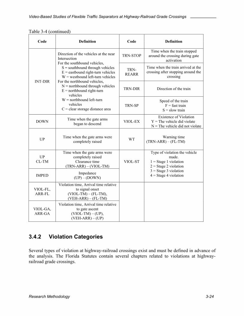
Table 3-4 (continued)
Code Definition Code Definition
TRN-STOP
Time when the train stopped around the crossing during gate
activation
TRN-REARR
Time when the train arrived at the crossing after stopping around the
crossing
TRN-DIR Direction of the train
INT-DIR
Direction of the vehicles at the near Intersection For the southbound vehicles, S = southbound through vehicles E = eastbound right-turn vehicles W = westbound left-turn vehicles For the northbound vehicles, N = northbound through vehicles E = northbound right-turn vehicles W = northbound left-turn vehicles C = clear storage distance area
TRN-SP Speed of the train
F = fast train S = slow train
DOWN Time when the gate arms began to descend VIOL-EX
Existence of Violation Y = The vehicle did violate N = The vehicle did not violate
UP Time when the gate arms were completely raised WT Warning time
(TRN-ARR) – (FL-TM)
UP CL-TM
Time when the gate arms were completely raised
Clearance time (TRN-ARR) – (VIOL-TM)
IMPED Impedance (UP) – (DOWN)
VIOL-ST
Type of violation the vehicle made.
1 = Stage 1 violation 2 = Stage 2 violation 3 = Stage 3 violation 4 = Stage 4 violation
VIOL-FL, ARR-FL
Violation time, Arrival time relative to signal onset
(VIOL-TM) – (FL-TM), (VEH-ARR) – (FL-TM)
VIOL-GA, ARR-GA
Violation time, Arrival time relative to gate ascent
(VIOL-TM) – (UP), (VEH-ARR) – (UP)
3.4.2 Violation Categories Several types of violation at highway-railroad crossings exist and must be defined in advance of the analysis. The Florida Statutes contain several chapters related to violations at highway-railroad grade crossings.
Research Methodology 3-24

Video-Based Studies of Flexible Traffic Separators at Highway-Railroad Grade Crossings
Under certain circumstances, Florida requires all persons driving a vehicle to stop within 50 feet but not less than 15 feet from the nearest rail at highway-railroad crossings. The stopping requirements are:
• Where the warning of an approaching train is given by clearly visible electrical or mechanical signal.
• Where a crossing gate is lowered or a human flagger gives or continues to give a signal of the approach or passage of a railroad train;
• Where an approaching railroad train emits an audible signal or the railroad train, by reason of its speed or nearness to the crossing, is an immediate hazard.
• Where an approaching railroad train is plainly visible and is in hazardous proximity to the railroad-highway grade crossing, regardless of the type of traffic control devices installed at the crossing.
Florida law also prohibits the driving of any vehicle through, around, or under any crossing gate or barrier at a railroad-highway grade crossing while the gate or barrier is closed or is being opened or closed. (Florida Statutes 316.1945) The detailed Florida laws extracted from the Florida Statutes and the Florida Driver’s Handbook are added in the Appendix B for further references. As described in the Florida Statutes above, drivers should stop within 50 feet, less than 15 feet in front of the nearest rail if they encounter any kind warning of train arrival. “The stop line should be placed approximately 2.4 m (8 ft) from the gate (if present), but no closer than 4.6 m (15 ft) from the nearest rail” (7). Longer distance than 15 feet (39 feet) could be found at the Park Road site to provide stopped vehicles on the tracks with space to clear the tracks backwards, just in case they cannot move forwards to clear the tracks due to the vehicle queue built up from the near intersection. However, “STOP HERE ON RED” sign next to the Park Road requires drivers to stop at the stop line. From these reasons, “15 feet” in the statute can be substituted by “stop line” at highway-railroad crossings. There are chances that drivers are not able to stop at the stop line with reasonable deceleration rates as soon as they see flashing lights begin. If the drivers just crossed the crossing because they were in a position where they would not be able to stop before the stop line with reasonable deceleration rates, they should be excluded from the violation categories. Engineering study was performed to find a stopping distance with which drivers of vehicles could have stopped at the stop line at the crossing with a reasonable deceleration as soon as they saw the flashing lights began. The stopping distance consists of braking distance (BRD) and the distance required for drivers to travel during perception-reaction time (PRD).
Braking distance (ft) = f
s30
2
where s = speed in miles per hour
f = coefficient of friction
Research Methodology 3-25
Video-Based Studies of Flexible Traffic Separators at Highway-Railroad Grade Crossings
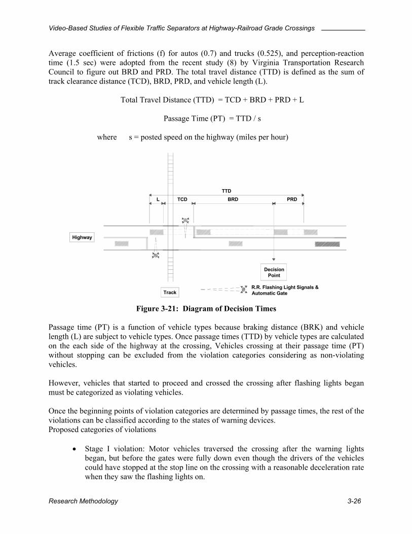
Average coefficient of frictions (f) for autos (0.7) and trucks (0.525), and perception-reaction time (1.5 sec) were adopted from the recent study (8) by Virginia Transportation Research Council to figure out BRD and PRD. The total travel distance (TTD) is defined as the sum of track clearance distance (TCD), BRD, PRD, and vehicle length (L).
Total Travel Distance (TTD) = TCD + BRD + PRD + L
Passage Time (PT) = TTD / s
where s = posted speed on the highway (miles per hour)
Highway
R.R. Flashing Light Signals & Automatic Gate
TCD
Track
BRD PRD
Decision Point
LTTD
Figure 3-21: Diagram of Decision Times Passage time (PT) is a function of vehicle types because braking distance (BRK) and vehicle length (L) are subject to vehicle types. Once passage times (TTD) by vehicle types are calculated on the each side of the highway at the crossing, Vehicles crossing at their passage time (PT) without stopping can be excluded from the violation categories considering as non-violating vehicles. However, vehicles that started to proceed and crossed the crossing after flashing lights began must be categorized as violating vehicles. Once the beginning points of violation categories are determined by passage times, the rest of the violations can be classified according to the states of warning devices. Proposed categories of violations
• Stage I violation: Motor vehicles traversed the crossing after the warning lights began, but before the gates were fully down even though the drivers of the vehicles could have stopped at the stop line on the crossing with a reasonable deceleration rate when they saw the flashing lights on.
Research Methodology 3-26

Video-Based Studies of Flexible Traffic Separators at Highway-Railroad Grade Crossings
• Stage II violation: Motor vehicles drove around the gate arms after the gates were fully deployed and before the train arrival.
• Stage III violation: Motor vehicles drove around the gate arms after the train departure and before the gates began to ascend.
• Stage IV violation: Motor vehicles traversed the crossing when the gates were being returned to their upright position.
The number of stage II and III violations directly refers to the number of vehicles driving around the gates at highway-railroad crossings. The method used at the Park Road site study to obtain passage time (PT) is described below.
Posted vehicle speed = 66 ft/sec (45 mph) Perception-Reaction time = 1.5 seconds Coefficient of friction (f) for auto = 0.7 Coefficient of friction (f) for trucks = 0.525 Table 3-5: Passage Times (PT) Calculated at Park Road Site (Northbound)
L (ft) TCD (ft) BRD (ft) PRD (ft) TT (sec) PT (sec) P 19 64.8 96.4 99 4.2 5.0 SU 30 64.8 128.6 99 4.9 BUS 40 64.8 128.6 99 5.0 WB 40 50 64.8 128.6 99 5.2 WB 50 55 64.8 128.6 99 5.3
6.0
Table 3-6: Passage Times (PT) Calculated at Park Road Site (Southbound)
L (ft) TCD (ft) BRD (ft) PRD (ft) TT (sec) PT (sec) P 19 45.8 96.4 99 3.9 4.0 SU 30 45.8 128.6 99 4.6 BUS 40 45.8 128.6 99 4.7 WB 40 50 45.8 128.6 99 4.9 WB 50 55 45.8 128.6 99 5.0
5.0
According to Passage times (PT) calculated above, northbound passenger cars, pick-ups, and vans crossing the tracks without stopping at less than 5 seconds after the flashing lights began, were considered to be non-violating vehicles. Similarly, northbound trucks, buses, and RV’s crossing the tracks without stopping at less than 5 seconds after the flashing lights began, were considered to be non-violating vehicles. It is recommended that this method be used for before and after studies about the number of violations because it will provide more reliable data than the previous methods. However, more studies should be conducted looking at the aspect of enforcement using this method. Pavement conditions (wet or dry), grade of the highway, design vehicle of the highway/railroad crossing, and application of a “grace period” should be the subjects of future studies.
Research Methodology 3-27

Video-Based Studies of Flexible Traffic Separators at Highway-Railroad Grade Crossings
3.4.3 Data Spreadsheets All of the observations from the data reduction step were incorporated into a set of spreadsheets, which are referenced as Appendix D of this report. Appendix D was delivered as a separate CD-ROM based document. Several important factors described below were automatically calculated in the spreadsheet from the raw observations. Warning time Drive-around violations can be substantially affected by the warning time, the duration from the signal onset to the train arrival. An acceptable warning time range of 20-35 seconds was suggested (1). If the warning time of a specific crossing is expected to be too long by large variation, it might be the cause of drive-around violations. Average and variation of warning times at the Park Road site was calculated for trains that entered the crossing. Some trains were involved in switching operations and either did not enter the crossing or entered it very slowly. In these cases, the warning time was not of interest to the study. Impedance Time The time during which the movements of vehicles are blocked by traffic control devices is called the impedance time. Vehicle delay caused by large impedance time may increase the number of violations at the crossing. Average and variation of impedances from each site was calculated as a part of the site characteristics. Clearance Time Clearance times of all recorded crossing vehicles were recorded as an indicator of the severity of violation. Time between the vehicle crossing time and the train arrival is called the clearance time.
3.4.4 Video Clips of Hazardous Events Video and picture clips of hazardous events were produced to check out the possible cause of violations. All of the picture clips for drive-around violations and other dangerous behaviors are included in Appendix C.
3.4.5 Study Schedule A summary of the videotape data collection activities is presented on the following pages.
Research Methodology 3-28

Video-Based Studies of Flexible Traffic Separators at Highway-Railroad Grade Crossings
Park Road Summary: Before Separator Installation Number of Violations by Stage
Tape # Date Start Time Duration Number of Activations
Number of Trains I II III IV Other
1 Feb/7 12:17:28 PM 22:44:56 21 21 8 20 2
2 Feb/8 11:05:29 AM 23:44:29 17 17 15 11
3 Feb/9 10:52:41 AM 23:23:39 9 9 1 5
4 Feb/10 10:17:32 AM 18:28:40 6 6 1 3
5 Feb/11 10:09:38 AM 23:49:39 17 17 11 8
6 Feb/12 10:00:51 AM 24:28:33 17 17 6 16 1
7 Feb/13 10:30:40 AM 24:11:24 20 20 26 1 1 22 1
8 Feb/14 10:43:10 AM 24:19:41 25 24 20 21
9 Feb/15 11:04:04 AM 23:27:59 18 18 16 1 1 16
10 Feb/16 10:32:37 AM 23:48:16 6 6 4 4
11 Feb/17 10:22:39 AM 24:12:06 10 10 4 4
12 Feb/18 10:36:17 AM 23:50:17 21 21 26 23
13 Feb/19 10:27:54 AM 24:11:20 22 21 22 23
14 Feb/20 10:40:46 AM 24:01:08 25 25 19 26
15 Feb/21 10:43:23 AM 24:14:07 24 22 17 17
16 Feb/22 10:58:27 AM 23:24:03 16 15 12 11
17 Feb/23 10:23:40 AM 23:32:48 Bad tape: no data
18 Feb/24 9:57:46 AM 24:32:49 9 9 6 6
19 Feb/25 10:33:42 AM 24:11:00 18 18 7 18 1
20 Feb/26 10:45:45 AM 24:10:11 22 22 19 18 1
21 Feb/27 10:57:26 AM 23:39:32 18 18 9 12
22 Feb/28 10:38:52 AM 21:33:08 18 18 13 17
23 Mar/1 10:36:15 AM 24:26:35 14 14 8 16 1
24 Mar/2 11:04:19 AM 23:40:44 6 6 5 7
25 Mar/3 10:46:28 AM 23:42:23 8 8 5 6
26 Mar/4 10:29:59 AM 24:10:08 17 17 15 13
27 Mar5 12:08:19 PM 22:51:06 23 23 18 23
28 Mar/6 11:00:28 AM 23:47:47 21 21 11 21 1
29 Mar/7 10:49:35 AM 23:41:13 24 24 24 16
30 Mar/8 10:32:20 AM 23:43:18 24 24 22 24 1
31 Mar/9 10:16:52 AM 23:36:18 7 7 3 2
32 Mar/10 9:54:23 AM 24:24:10 9 9 1 7
33 Mar/11 2:01:17 PM 20:46:19 15 15 9 14
34 Mar/12 11:40:37 AM 23:01:32 16 16 7 15
35 Mar/13 10:43:29 AM 24:05:05 21 21 22 1 23
36 Mar/14 10:49:53 AM 24:00:45 22 21 20 22
37 Mar/15 10:51:41 AM 23:56:26 15 15 9 13
38 Mar/16 10:48:59 AM 23:39:11 8 8 6 4
39 Mar/17 10:29:23 AM 24:07:44 9 9 8 11
40 Mar/18 10:38:13 AM 24:18:35 18 18 17 19
41 Mar19 10:58:02 AM 23:43:11 21 20 11 19 2
Research Methodology 3-29
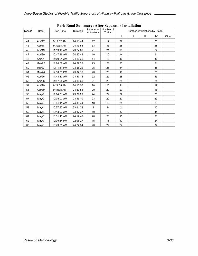
Video-Based Studies of Flexible Traffic Separators at Highway-Railroad Grade Crossings
Park Road Summary: After Separator Installation Tape # Date Start Time Duration Number of
ActivationsNumber of
Trains Number of Violations by Stage I II III IV Other
44 Apr/17 9:19:32 AM 24:11:44 17 17 27 23
45 Apr/18 9:32:38 AM 24:13:51 33 33 28 28
46 Apr/19 11:19:19 AM 23:27:08 21 21 38 24
47 Apr/20 10:47:16 AM 24:20:49 10 10 9 11
48 Apr/21 11:09:21 AM 24:10:36 14 13 16 6
49 Mar/22 11:20:52 AM 24:27:28 23 23 23 21
50 Mar23 12:11:11 PM 23:58:22 25 25 44 38
51 Mar/24 12:10:31 PM 23:37:18 20 20 16 25
52 Apr/25 11:48:37 AM 23:57:11 22 22 28 35
53 Apr/26 11:47:05 AM 24:16:39 21 20 24 24
54 Apr/29 9:21:55 AM 24:15:55 20 20 21 19
55 Apr/30 9:44:38 AM 24:30:54 20 20 27 18
56 May/1 11:04:31 AM 23:29:29 24 24 22 28
57 May/2 10:35:00 AM 23:55:10 23 22 20 29
58 May/3 10:31:11 AM 24:09:41 18 18 25 23
59 May/4 10:57:33 AM 23:44:32 9 9 2 10
60 May/5 10:43:03 AM 23:47:37 10 10 6 9
61 May/6 10:31:43 AM 24:17:48 20 20 15 23
62 May/7 12:39:34 PM 22:08:27 15 15 10 24
63 May/8 10:49:01 AM 24:27:34 26 22 27 32
Research Methodology 3-30
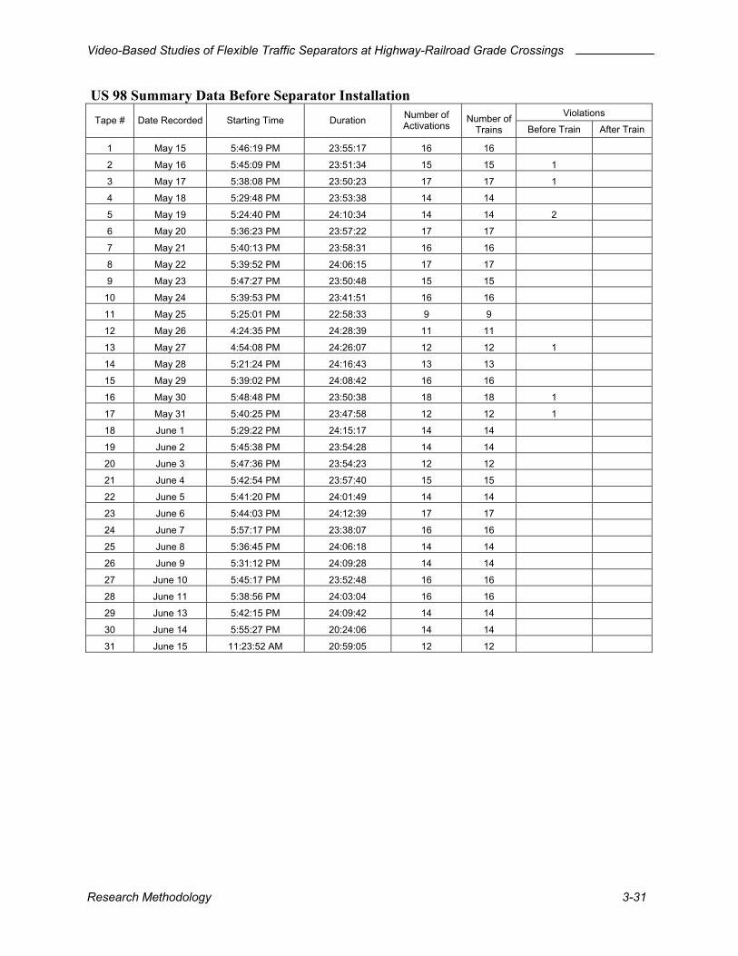
Video-Based Studies of Flexible Traffic Separators at Highway-Railroad Grade Crossings
US 98 Summary Data Before Separator Installation Violations
Tape # Date Recorded Starting Time Duration Number of Activations Before Train After Train
1 May 15 5:46:19 PM 23:55:17 16
2 May 16 5:45:09 PM 15 15 1
3 May 17 23:50:23 17 17 1
4 5:29:48 PM 23:53:38 14 14
May 19 5:24:40 PM 24:10:34 14 14 2
6 May 20 5:36:23 PM 23:57:22 17 17
7 May 21 5:40:13 PM 23:58:31 16 16
8 May 22 5:39:52 PM 24:06:15 17
9 May 23 5:47:27 PM 23:50:48
Number of Trains
16
23:51:34
5:38:08 PM
May 18
5
17
15 15
10 May 24 5:39:53 PM 23:41:51 16 16
11 May 25 5:25:01 PM 22:58:33 9 9
12 May 26 4:24:35 PM 24:28:39 11 11
13 May 27 4:54:08 PM 24:26:07 12 12 1
14 May 28 5:21:24 PM 24:16:43 13 13
15 May 29 5:39:02 PM 24:08:42 16 16
16 May 30 5:48:48 PM 23:50:38 18 18 1
17 May 31 5:40:25 PM 23:47:58 12 12 1
18 June 1 5:29:22 PM 24:15:17 14 14
19 June 2 5:45:38 PM 23:54:28 14 14
20 June 3 5:47:36 PM 23:54:23 12 12
21 June 4 5:42:54 PM 23:57:40 15 15
22 June 5 5:41:20 PM 24:01:49 14 14
23 June 6 5:44:03 PM 24:12:39 17 17
24 June 7 5:57:17 PM 23:38:07 16 16
25 June 8 5:36:45 PM 24:06:18 14 14
26 June 9 5:31:12 PM 24:09:28 14 14
27 June 10 5:45:17 PM 23:52:48 16 16
28 June 11 5:38:56 PM 24:03:04 16 16
29 June 13 5:42:15 PM 24:09:42 14 14
30 June 14 5:55:27 PM 20:24:06 14 14
31 June 15 11:23:52 AM 20:59:05 12 12
Research Methodology 3-31

Video-Based Studies of Flexible Traffic Separators at Highway-Railroad Grade Crossings
US 98 Summary Data After Separator Installation Violations
Tape # Date Recorded Starting Time Duration Number of Activations
Number of Trains Before Train After Train
32 June 27 5:37:46 PM 24:07:42 14 13
33 June 28 5:46:31 PM 23:37:45 16 16
34 June 29 5:27:53 PM 23:46:21 12 12
35 June 30 5:10:34 PM 24:12:25 13 13
36 July 1 5:23:45 PM 23:34:44 13 13
37 July 2 7:29:08 PM 16:00:03 11 11
38 July 3 7:29:11 PM 22:23:11 9 9
39 July 4 5:53:14 PM 23:25:59 8 8
40 July 5 5:30:02 PM 24:03:51 12 12
41 July 6 5:34:38 PM 23:52:19 15 15
42 July 7 5:27:41 PM 24:16:36 14 14
43 July 8 5:43:59 PM 23:57:07 13 13
44 July 9 5:42:06 PM 23:59:00 15 15
45 July 10 5:42:04 PM 24:01:02 16 16
46 July 11 5:44:46 PM 23:43:13 16 16
47 July 12 5:29:07 PM 24:35:41 17 17 1
48 July 13 6:18:00 PM 24:10:02 8 8
49 July 14 6:29:15 PM 23:10:37 16 16
50 July 15 5:41:45 PM 24:00:39 16 16
51 July 16 5:44:03 PM 23:57:12 15 15
52 July 17 5:42:35 PM 23:57:52 16 16
53 July 18 5:41:13 PM 23:35:29 17 17
Research Methodology 3-32

Video-Based Studies of Flexible Traffic Separators at Highway-Railroad Grade Crossings
SR 17 Summary Data Before Separator Installation Violations
Tape # Date Recorded Starting Time Duration Number of Activations Number of
Trains Before Train After Train
1 May 14 7:28:47 AM 23:30:48 26 17 7 0
2 May 16 5:58:39 AM 23:50:24 26 26 2 0
3 May 17 5:50:31 AM 23:50:24 8 8 0 0
4 May 18 5:41:48 PM 23:54:07 18 16 2 0
5 May 19 5:38:16 PM 24:08:75 21 12 1 0
6 May 20 5:48:31 PM 24:02:48 24 19 0 0
7 May 21 5:52:49 PM 23:59:10 18 18 0 0
8 May 22 5:53:20 PM 24:04:41 16 16 0 0 9 May 23 5:59:28 PM 23:52:35 18 18 1 0
10 May 24 5:54:34 PM 23:12:34 16 16 1 0
11 May 25 5:38:31 PM 22:56:57 11 11 0 0
12 May 26 4:36:29 PM 24:24:48 12 12 0 0
13 May 27 5:05:01 PM 23:35:12 13 12 0 0
14 May 28 5:32:19 PM 24:13:10 17 17 1 0
15 May 29 5:50:28 PM 24:08:07 17 17 0 0
16 May 30 5:59:31 PM 23:51:26 17 16 0 0
17 May 31 5:51:46 PM 23:53:46 16 16 0 0
18 June 01 5:46:31 PM 23:49:33 12 12 0 0
19 June 02 5:58:00 PM 24:02:26 15 15 0 0
20 June 03 6:10:39 PM 23:44:01 15 15 1 0
21 June 04 5:55:28 PM 23:56:47 15 15 0 0
22 June 05 5:51:55 PM 24:02:10 16 15 0 0
23 June 06I 5:57:58 PM 24:12:05 37 16 1 0
24 June 07 6:13:16 PM 23:26:47 16 16 0 0
25 June 08 5:48:06 PM 23:54:40 14 14 0 0
26 June 09 5:47:28 PM 10:25:34 7 7 1 0
27 June 10 5:57:00 PM 1:41:24 2 2 0 0
28 June 11 5:50:26 PM 24:03:29 17 17 0 0
29 June 12 5:54:59 PM 23:04:32 17 15 0 0
30 June 13 5:53:15 PM 24:10:09 19 15 0 0
31 June 14 6:04:22 PM 13:30:53 15 15 0 0
32 June 15 11:35:01 AM 21:54:58 13 13 0 0
33 June 16 8:44:15 AM 24:49:41 16 13 1 0
Research Methodology 3-33

Video-Based Studies of Flexible Traffic Separators at Highway-Railroad Grade Crossings
SR 17 Summary Data After Separator Installation Violations
Tape # Date Recorded Starting Time Duration Number of Activations Number of
Trains Before Train After Train
34 June 26 17:07:40 23:18:46 19 11 0 0
35 June 27 16:50:49 23:13:14 16 10 0 0
36 June 28 16:37:48 24:02:46 18 6 0 0
37 June 29 16:42:16 24:11:39 16 4 0 0
38 June 30 17:32:56 24:03:25 17 7 0 0
39 July 1 17:36:14 23:51:47 17 9 0 0
40 July 2 17:28:24 21:45:51 13 6 0 0
41 July 3 18:10:20 23:28:30 10 6 0 0
42 July 4 17:43:37 23:58:52 9 8 0 0
43 July 5 17:47:24 23:59:36 11 5 0 0
44 July 6 17:46:49 23:54:29 15 7 0 0
45 July 7 17:41:03 24:14:19 14 9 0 0
46 July 8 17:56:18 24:04:10 16 10 0 0
47 July 9 18:01:05 23:08:43 20 11 0 0
48 July 10 17:54:29 24:02:31 17 9 0 0
49 July 11 17:56:52 23:44:51 16 10 0 0
50 July 12 17:41:43 24:09:12 18 9 0 0
51 July 13 18:28:58 24:13:40 11 10 0 0
52 July 14 18:43:46 23:50:59 16 16 0 0
53 July 15 17:54:54 23:11:48 17 16 0 0
54 July 16 18:01:22 23:05:45 21 17 0 0
55 July 17 17:57:43 23:56:52 27 15 0 0
56 July 18 17:54:21 24:47:19 18 18 0 0
57 July 19 18:08:21 23:15:42 19 16 0 0
58 July 20 17:55:31 24:50:03 12 12 0 0
59 July 21 18:06:08 23:14:53 15 15 0 0
Research Methodology 3-34

Video-Based Studies of Flexible Traffic Separators at Highway-Railroad Grade Crossings
4 STUDY RESULTS
4.1 Anecdotal Results Eight events were observed that could best be described in anecdotal terms. Each of these events will be described separately.
4.1.1 Damaged Gate During the course of this study, several heavy vehicles interacted with the gate arms at the Park Road site. This example is indicative of the types of situations in which the gate arms would collide with the trailer of the heavy vehicle, in each case a semi-trailer. The stopped vehicle began to move during the traffic-signal queue clearance opportunity. As a result of the slow acceleration capability and long length of semi-trailers, an increased risk of gate arm interaction accompanies violations of this type. In one instance, the gate arm closed on top of a trailer before the truck could clear the crossing. The gate arm was damaged as it attempted to proceed to its fully closed position. In this instance, the gate arm was bent but remained operational. The damage went unnoticed when trains approached the crossing from one direction as they only brushed against the gate arm. However, when a train approached from the opposite direction of the gate arm’s operation, it collided head-on with the damaged gate arm, completely destroying it. In another instance, the violating semi-trailer stopped when it was unable to clear the crossing before interacting with the gate arm. A slowly approaching train was forced to stop so that the semi-trailer could be cleared from the crossing.
4.1.2 QWICK KURB® Hit Significant damage was recorded to a Quick KURB® installation at the US 98 site. Nine consecutive markers were completely removed from the traffic separator, apparently from the impact of a large motor vehicle such as a semi-trailer. Factors that may have contributed to the collision include narrow lane width (9.2 feet) and the number of lanes (2). With additional lanes, motorists have the ability to compensate for the presence of the traffic separator and may be able to avoid collision with the markers. The manufacturer made repairs to the damaged markers in a timely manner.
Study Results 4-1
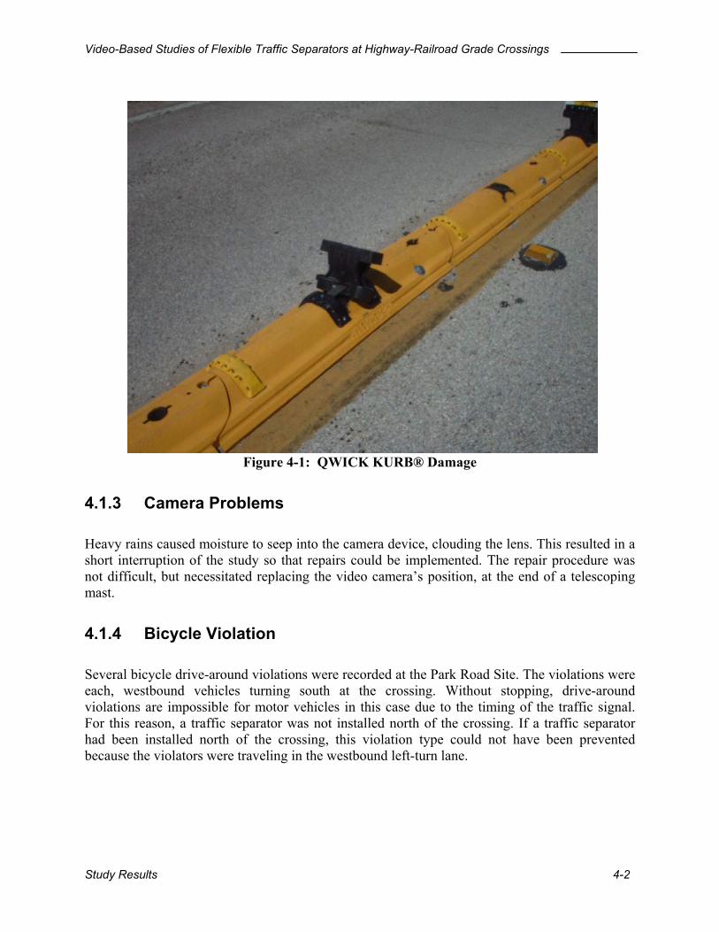
Video-Based Studies of Flexible Traffic Separators at Highway-Railroad Grade Crossings
Figure 4-1: QWICK KURB® Damage
.1.3 Camera Problems
eavy rains caused moisture to seep into the camera device, clouding the lens. This resulted in a
.1.4 Bicycle Violation
everal bicycle drive-around violations were recorded at the Park Road Site. The violations were
4 Hshort interruption of the study so that repairs could be implemented. The repair procedure was not difficult, but necessitated replacing the video camera’s position, at the end of a telescoping mast.
4 Seach, westbound vehicles turning south at the crossing. Without stopping, drive-around violations are impossible for motor vehicles in this case due to the timing of the traffic signal. For this reason, a traffic separator was not installed north of the crossing. If a traffic separator had been installed north of the crossing, this violation type could not have been prevented because the violators were traveling in the westbound left-turn lane.
Study Results 4-2
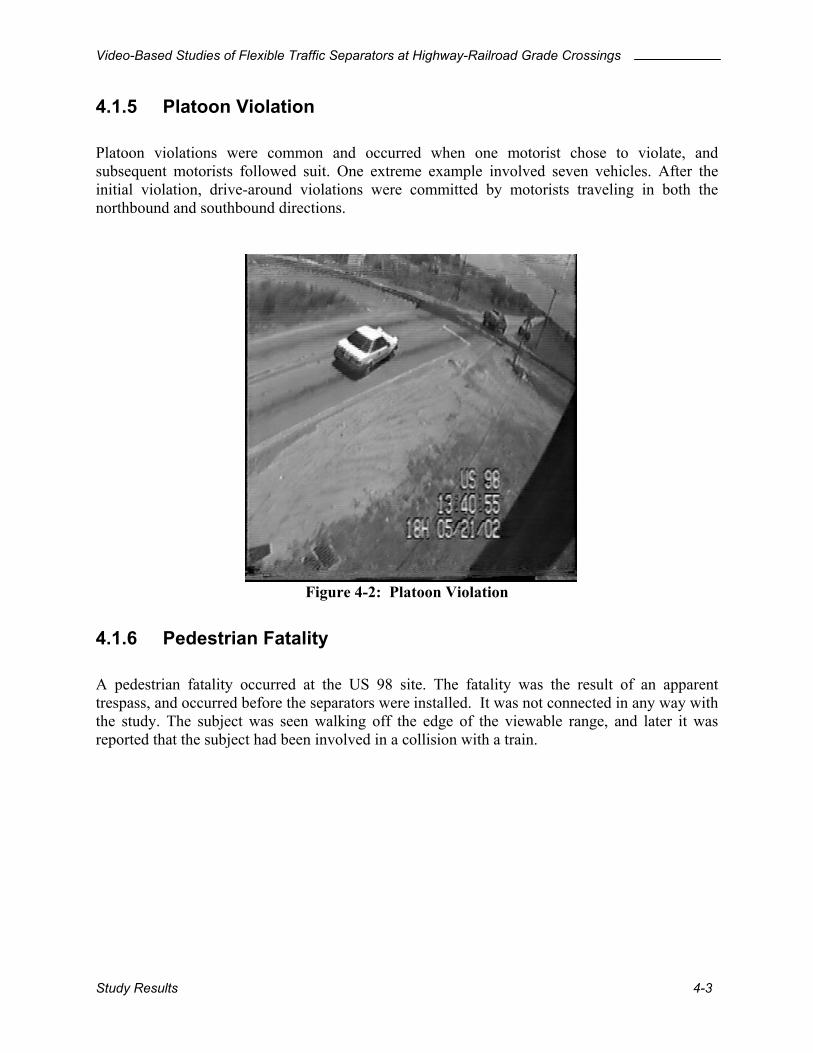
Video-Based Studies of Flexible Traffic Separators at Highway-Railroad Grade Crossings
4.1.5 Platoon Violation Platoon violations were common and occurred when one motorist chose to violate, and subsequent motorists followed suit. One extreme example involved seven vehicles. After the initial violation, drive-around violations were committed by motorists traveling in both the northbound and southbound directions.
Figure 4-2: Platoon Violation
.1.6 Pedestrian Fata
S 98 site. The fatality was the result of an apparent espass, and occurred before the separators were installed. It was not connected in any way with
4 lity A pedestrian fatality occurred at the Utrthe study. The subject was seen walking off the edge of the viewable range, and later it was reported that the subject had been involved in a collision with a train.
Study Results 4-3
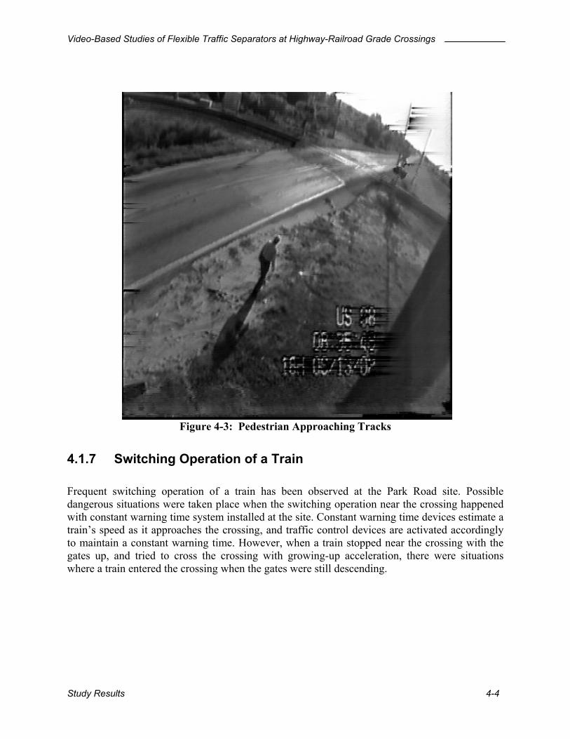
Video-Based Studies of Flexible Traffic Separators at Highway-Railroad Grade Crossings
Figure 4-3: Pedestrian Approaching Tracks
4.1.7 Switching Operation of a Train Frequent switching operation of a train has been observed at the Park Road site. Possible dangerous situations were taken place when the switching operation near the crossing happened with constant warning time system installed at the site. Constant warning time devices estimate a train’s speed as it approaches the crossing, and traffic control devices are activated accordingly to maintain a constant warning time. However, when a train stopped near the crossing with the gates up, and tried to cross the crossing with growing-up acceleration, there were situations where a train entered the crossing when the gates were still descending.
Study Results 4-4

Video-Based Studies of Flexible Traffic Separators at Highway-Railroad Grade Crossings
4.1.8 Gate Violation after the Separators Were Installed The “before and after” studies summarized later in this section indicate that 26 violations were observed in the period before the installation of the traffic separators and only one violation was observed after the separators were installed. Because of the singular nature of this violation, it will be reported here as an anecdotal event. The violation happened at approximately 4:30 PM on July 13, 2002. The chronology is as follows:
Event Clock Time Elapsed Time Gate descent 16:26:39 0:00 First vehicle arrived (semi trailer) 16:29:14 2:35 Offending (4th) vehicle joined the queue 16:30:21 3:42 Offending vehicle crossed into the oncoming traffic lane 16:30:56 4:17 Offending vehicle cleared the tracks 16:31:12 4:33 Train arrived 16:33:33 6:54
For reasons that were not observable on the videotape, the gates were down for nearly seven minutes before the train arrived. The offending vehicle joined the back of the waiting queue and waited for 35 seconds before pulling into the oncoming traffic lane, bypassing the other vehicles in the queue and entering the crossing on the wrong side of the road. A photograph of the offending vehicle as it is about to enter the crossing is shown below.
Five additional vehicles joined the back of the queue after the offending vehicle departed. None of these vehicles committed a gate violation, although one of them (the last one) left the queue and executed a U turn to proceed in the opposite direction.
Study Results 4-5

Video-Based Studies of Flexible Traffic Separators at Highway-Railroad Grade Crossings
4.2 Before and After Separator Installation Analysis
4.2.1 Park Road Overall Violations The proposed categories of violation study mentioned earlier in Chapter 2 were used to compare the number of violations for before and after study. Passage times (PT) depend on the vehicle types that have different lengths and braking distances as shown in Table 2-6. The vehicles, which crossed the crossing without stopping at their passage times, were excluded from the stage I category. However, vehicles, which started moving and crossed after the flashing lights began, were counted as violations. The study was performed for both north and southbound even though traffic separator was installed on the south of the tracks.
Flasher OnlyFlasher + Descending Gates
TRAIN PASSAGEFlasher +
Downed Gates
Flasher + Ascending Gates
Warning Devices
Gate Position
Proposed Definition STAGE I STAGE II STAGE III STAGE IV
Flasher + Downed Gates
( PT )
Figure 4-4: Proposed Categories of Violations Proposed categories of violation
• Stage I violation: Motor vehicles traversed the crossing after the warning lights began, but before the gates were fully down even though the drivers of the vehicles could have stopped at the stop line on the crossing with a reasonable deceleration rate when they saw the flashing lights on.
• Stage II violation: Motor vehicles drove around the gate arms after the gates were fully deployed and before the train arrival.
• Stage III violation: Motor vehicles drove around the gate arms after the train departure and before the gates began to ascend.
• Stage IV violation: Motor vehicles traversed the crossing when the gates were being returned to their upright position.
Study Results 4-6
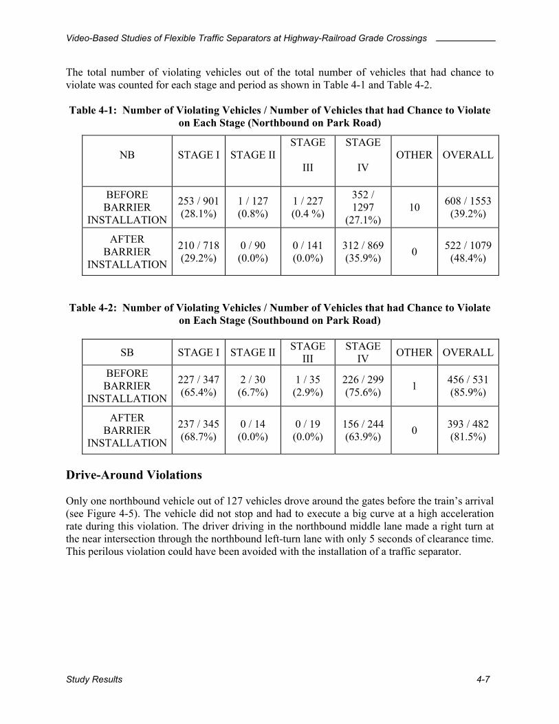
Video-Based Studies of Flexible Traffic Separators at Highway-Railroad Grade Crossings
The total number of violating vehicles out of the total number of vehicles that had chance to violate was counted for each stage and period as shown in Table 4-1 and Table 4-2. Table 4-1: Number of Violating Vehicles / Number of Vehicles that had Chance to Violate
on Each Stage (Northbound on Park Road)
NB STAGE I STAGE IISTAGE
III
STAGE
IV OTHER OVERALL
BEFORE BARRIER
INSTALLATION
253 / 901 (28.1%)
1 / 127 (0.8%)
1 / 227 (0.4 %)
352 / 1297
(27.1%) 10 608 / 1553
(39.2%)
AFTER BARRIER
INSTALLATION
210 / 718 (29.2%)
0 / 90 (0.0%)
0 / 141 (0.0%)
312 / 869 (35.9%) 0 522 / 1079
(48.4%)
Table 4-2: Number of Violating Vehicles / Number of Vehicles that had Chance to Violate on Each Stage (Southbound on Park Road)
SB STAGE I STAGE II STAGE III
STAGE IV OTHER OVERALL
BEFORE BARRIER
INSTALLATION
227 / 347 (65.4%)
2 / 30 (6.7%)
1 / 35 (2.9%)
226 / 299 (75.6%) 1 456 / 531
(85.9%)
AFTER BARRIER
INSTALLATION
237 / 345 (68.7%)
0 / 14 (0.0%)
0 / 19 (0.0%)
156 / 244 (63.9%) 0 393 / 482
(81.5%)
Drive-Around Violations Only one northbound vehicle out of 127 vehicles drove around the gates before the train’s arrival (see Figure 4-5). The vehicle did not stop and had to execute a big curve at a high acceleration rate during this violation. The driver driving in the northbound middle lane made a right turn at the near intersection through the northbound left-turn lane with only 5 seconds of clearance time. This perilous violation could have been avoided with the installation of a traffic separator.
Study Results 4-7

Video-Based Studies of Flexible Traffic Separators at Highway-Railroad Grade Crossings
Figure 4-5: Northbound Drive-Around Violation Prior to Train Arrival Only one northbound vehicle out of 227 vehicles drove around the gates after the train’s arrival (see Figure 4-6). The vehicle arrived at the northbound middle lane when the gates were down with a stopped train near the crossing. The driver drove around the gates to the intersection stop line as soon as the train started moving away from the crossing. The switching operations of trains may induce drivers to drive around the gates because the drivers can see the slow movement of the train and decide they can make the movement safely. This behavior could be disastrous especially if there is more than one track at the crossing, as with the Park Road site. The vehicles that drive around these gates might conflict with an approaching train on other tracks.
Study Results 4-8

Video-Based Studies of Flexible Traffic Separators at Highway-Railroad Grade Crossings
Figure 4-6: Northbound Drive-Around Violation During Train Switching Operations Two westbound left-turning bicycles at the near intersection drove around the gates to the south during the night (see Figure 4-7). One bicycle violated before the train with only 3 seconds of clearance time, and the other violated 6 seconds after the train’s departure. The drivers drove around the gates without stopping, ignoring the traffic signals at the near intersection during queue clearance time. Both violations could not have been prevented by the traffic separator because of the direction of the bicycles. One eastbound right-turn bicycle drove around the gates to the south 42 seconds after the gates were completely down. The long warning times caused by the switching operations of the trains could be the cause for the violations in this case. A traffic separator might have discouraged this violation.
Study Results 4-9
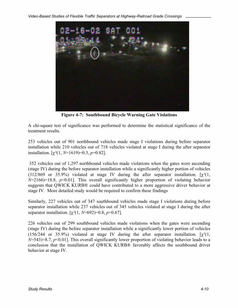
Video-Based Studies of Flexible Traffic Separators at Highway-Railroad Grade Crossings
Figure 4-7: Southbound Bicycle Warning Gate Violations A chi-square test of significance was performed to determine the statistical significance of the treatment results. 253 vehicles out of 901 northbound vehicles made stage I violations during before separator installation while 210 vehicles out of 718 vehicles violated at stage I during the after separator installation. [χ²(1, N=1619)=0.3, p=0.82]. 352 vehicles out of 1,297 northbound vehicles made violations when the gates were ascending (stage IV) during the before separator installation while a significantly higher portion of vehicles (312/869 or 35.9%) violated at stage IV during the after separator installation. [χ²(1, N=2166)=18.8, p<0.01]. This overall significantly higher proportion of violating behavior suggests that QWICK KURB® could have contributed to a more aggressive driver behavior at stage IV. More detailed study would be required to confirm these findings Similarly, 227 vehicles out of 347 southbound vehicles made stage I violations during before separator installation while 237 vehicles out of 345 vehicles violated at stage I during the after separator installation. [χ²(1, N=692)=0.8, p=0.67]. 226 vehicles out of 299 southbound vehicles made violations when the gates were ascending (stage IV) during the before separator installation while a significantly lower portion of vehicles (156/244 or 35.9%) violated at stage IV during the after separator installation. [χ²(1, N=543)=8.7, p<0.01]. This overall significantly lower proportion of violating behavior leads to a conclusion that the installation of QWICK KURB® favorably affects the southbound driver behavior at stage IV.
Study Results 4-10

Video-Based Studies of Flexible Traffic Separators at Highway-Railroad Grade Crossings
Driver Behavior of Approaching Vehicles Before the Gates are Completely Down A more detailed study was carried out to determine the crossing behaviors from the signal onset until the gates are completely down. Figure 4-8, Figure 4-9 and Figure 4-10 show crossing or stopping behavior of drivers who approach the crossing at each time point before the gates are completely down. In the table, flashing lights began at “0” second, gates began to descend at “5” second, and gates were complete down at “19” seconds at the Park Road Site.
0
20
40
60
80
100
120
140
1 2 3 4 5 6 7 8 9 10 11 12 13 14 15 16 17 18ARRIVAL TIME
(seconds after the onset of flashing lights)
NU
MB
ER O
F VE
HIC
LES
Crossed without stoppingStopped and waited
Figure 4-8: Crossing and Stopping Driver Behavior Before the Gates are Down (Northbound Before Separator Installation)
Study Results 4-11

Video-Based Studies of Flexible Traffic Separators at Highway-Railroad Grade Crossings
0
20
40
60
80
100
1 2 3 4 5 6 7 8 9 10 11 12 13 14 15 16 17 18ARRIVAL TIME
(seconds after the onset of flashing lights)
NU
MB
ER O
F VE
HIC
LES
Crossed without stoppingStopped and Waited
Figure 4-9: Crossing and Stopping Driver Behavior Before the Gates are Down (Northbound After Separator Installation)
0
20
40
60
80
100
1~2 3~4 5~6 7~8 9~10 11~12 13~14 15~16 17~18
ARRIVAL TIME(seconds after the onset of flashing lights)
PRO
BA
BIL
ITY
OF
CR
OSS
ING
(%)
Before SeparatorsAfter Separators
Figure 4-10: Probability of Stopping Before the Gates are Down (Northbound Before and After Separator Installation)
Study Results 4-12
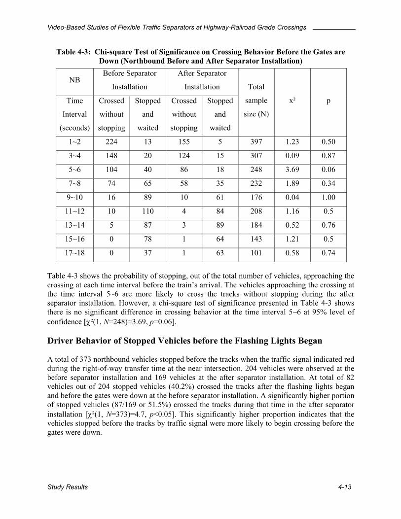
Video-Based Studies of Flexible Traffic Separators at Highway-Railroad Grade Crossings
Table 4-3: Chi-square Test of Significance on Crossing Behavior Before the Gates are Down (Northbound Before and After Separator Installation)
NB Before Separator
Installation
After Separator
Installation
Time
Interval
(seconds)
Crossed
without
stopping
Stopped
and
waited
Crossed
without
stopping
Stopped
and
waited
Total
sample
size (N)
x² p
1~2 224 13 155 5 397 1.23 0.50
3~4 148 20 124 15 307 0.09 0.87
5~6 104 40 86 18 248 3.69 0.06
7~8 74 65 58 35 232 1.89 0.34
9~10 16 89 10 61 176 0.04 1.00
11~12 10 110 4 84 208 1.16 0.5
13~14 5 87 3 89 184 0.52 0.76
15~16 0 78 1 64 143 1.21 0.5
17~18 0 37 1 63 101 0.58 0.74
Table 4-3 shows the probability of stopping, out of the total number of vehicles, approaching the crossing at each time interval before the train’s arrival. The vehicles approaching the crossing at the time interval 5~6 are more likely to cross the tracks without stopping during the after separator installation. However, a chi-square test of significance presented in Table 4-3 shows there is no significant difference in crossing behavior at the time interval 5~6 at 95% level of confidence [χ²(1, N=248)=3.69, p=0.06]. Driver Behavior of Stopped Vehicles before the Flashing Lights Began A total of 373 northbound vehicles stopped before the tracks when the traffic signal indicated red during the right-of-way transfer time at the near intersection. 204 vehicles were observed at the before separator installation and 169 vehicles at the after separator installation. At total of 82 vehicles out of 204 stopped vehicles (40.2%) crossed the tracks after the flashing lights began and before the gates were down at the before separator installation. A significantly higher portion of stopped vehicles (87/169 or 51.5%) crossed the tracks during that time in the after separator installation [χ²(1, N=373)=4.7, p<0.05]. This significantly higher proportion indicates that the vehicles stopped before the tracks by traffic signal were more likely to begin crossing before the gates were down.
Study Results 4-13

Video-Based Studies of Flexible Traffic Separators at Highway-Railroad Grade Crossings
Driver Behavior of Stopped Vehicles before the Gates Started to Ascend A total of 2,092 northbound vehicles stopped ahead of the tracks before the gates began to ascend. 1,254 vehicles were observed at the before separator installation, 838 vehicles at the after separator installation. 342 vehicles out of 1,254 stopped vehicles (27.3%) crossed the tracks when the gates were ascending. A significantly higher portion of stopped vehicles (299/838 or 35.7%) crossed the tracks during that time in the after separator installation [χ²(1, N=2092)=16.7, p<0.01]. This significantly higher proportion indicates that the vehicles stopped ahead of the tracks before the gates began to ascend, were more likely to start to cross before the gates had returned to their upright position. Warning time and Impedance Time The average warning time for trains that were not involved in switching at the Park Road crossing was 29.7 seconds, with a standard deviation was 9.4 seconds for the before separator installation study. Overall, they were in the acceptable range of 20~35 seconds found in the literature. With a reasonable average and acceptable standard deviation, drivers might have just a little chance of being misled by the warning times applied to the Park Road site. Average impedance time was 95 seconds with a standard deviation of 76 seconds. More than 5 minutes of impedance times were found in 20 gate activations out of 659 gate activations (0.3%). The 20 activations mostly occurred with the switching operations of trains.
4.2.2 US 98 and SR 17 A total of 31 before-separator installation tapes (one tape per day) from the US 98 site and 33 before-separator installation tapes (one tape per day) from the SR 17 site have been observed for drive-around violations. The number of drive-around vehicles out of the total number of vehicles that had chance to drive around was counted for the before separator installation and will be compared with the values from the after separator installation. Drive-Around Violations Seven drive-around violations before and after the train arrival have been observed at the US 98 site, including one violation after the separators were installed. All occurrences happened at different times except that two violations occurred in the same group. Unexpectedly, one pedestrian proceeded to cross by walking around the gates at midnight with clearance time of 41 seconds. All of the detailed information and picture clips of drive-around violations are included in Appendix C.
Study Results 4-14
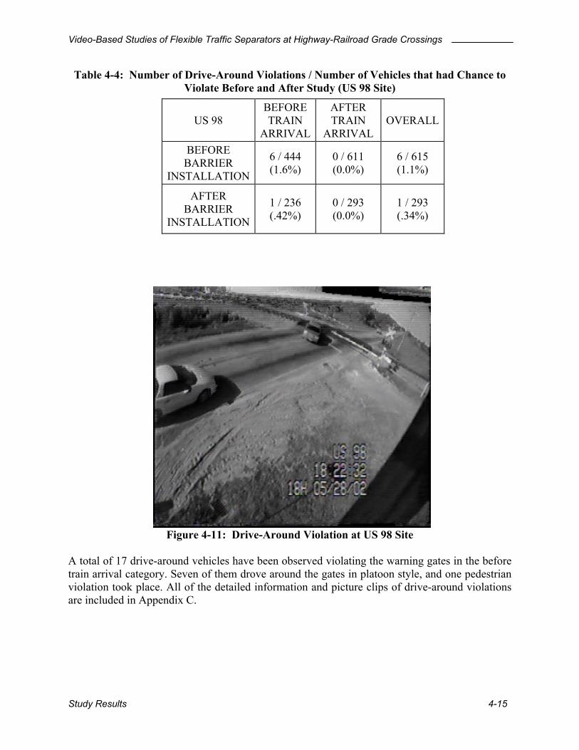
Video-Based Studies of Flexible Traffic Separators at Highway-Railroad Grade Crossings
Table 4-4: Number of Drive-Around Violations / Number of Vehicles that had Chance to Violate Before and After Study (US 98 Site)
US 98 BEFORE TRAIN
ARRIVAL
AFTER TRAIN
ARRIVAL OVERALL
BEFORE BARRIER
INSTALLATION
6 / 444 (1.6%)
0 / 611 (0.0%)
6 / 615 (1.1%)
AFTER BARRIER
INSTALLATION
1 / 236 (.42%)
0 / 293 (0.0%)
1 / 293 (.34%)
Figure 4-11: Drive-Around Violation at US 98 Site
A total of 17 drive-around vehicles have been observed violating the warning gates in the before train arrival category. Seven of them drove around the gates in platoon style, and one pedestrian violation took place. All of the detailed information and picture clips of drive-around violations are included in Appendix C.
Study Results 4-15

Video-Based Studies of Flexible Traffic Separators at Highway-Railroad Grade Crossings
Table 4-5: Number of Drive-Around Vehicles / Number of Vehicles that had Chance to Violate Before and After Study (SR 17 Site)
SR 17 BEFORE TRAIN
ARRIVAL
AFTER TRAIN
ARRIVAL OVERALL
BEFORE BARRIER
INSTALLATION
17 / 267 (6.7%)
0 / 453 (0.0%)
17 / 457 (3.9%)
AFTER BARRIER
INSTALLATION
0 / 160 (0.0%)
0 / 293 (0.0%)
0 / 293 (0.0%)
Figure 4-12: Drive-Around Violation at SR 17 Site
Study Results 4-16

Video-Based Studies of Flexible Traffic Separators at Highway-Railroad Grade Crossings
5 CONCLUSIONS AND RECOMMENDATIONS The results of this study include a prototype video surveillance system suitable for deployment at highway-railroad grade crossings and an assessment of the effectiveness of the QWICK KURB® traffic separator devices at three crossing sites in central Florida. Recommendations for future deployment and for future studies are also provided. These studies were based on an extensive data collection effort. A total of 4,004 hours of video taped operation involving 2,624 train crossing events was observed manually to assess the effectiveness of the traffic separators. In spite of this lengthy analysis period, there were fewer than expected violations observed in the before separator installation. The small number of before-separator installation violations makes it more difficult to draw strong conclusions from the before and after studies. Recognizing this limitation, the following conclusions are offered:
5.1 Effectiveness of QWICK KURB® in Preventing Drive-Around Violations
No drive-around violations were found after the installation of QWICK KURB® at the Park Road site for 21 days of after study separator installation. However, the effectiveness of the QWICK KURB® could not be statistically analyzed because only two northbound drive-around violations took place in the 42 days before the separator installation. The drive-around rate (2 out of 649 train passages) is quite low compared to the rates (0.19 per train for Andersonville Road, 0.33 per train for Eckles Road) found in another QWICK KURB® study reported in Reference 4. The following factors might have contributed to discouraging northbound drivers from driving around the gates at the Park Road site in the period before the installation.
• The trajectories of vehicles driving around the gates: Left-turning vehicles on the left-turn only lane must make a zigzag pattern to drive around the gates, and through and right-turning vehicles must make a wide turn through the left-turn only lane to do so.
• Turning lane volumes and left turn only lane: The observed northbound left turn only
lane volumes were lower than the northbound through and right turn shared lane volumes (left turn lane:120 vehicles, through lane:337vehicles, right turn shared lane: 451vehicles observed during before separator installation). This is important because right turning vehicles apparently have less chance of driving around the gates. Right turning drivers must across two lanes and make a sharp turn when there is no blockage in two lanes next to right turn lane to drive around the gates.
However, the installation of QWICK KURB® at the Park Road site might be crucially effective after all, in that a collision is more likely to happen when motorists have to take more risk when they decide to drive around the gates. Severity of violations is very important since highway-railroad crossing collisions are rare. The characteristics of the Park Road site increase risks associated with violations, and therefore the importance of countermeasures.
Conclusions and Recommendations 5-1

Video-Based Studies of Flexible Traffic Separators at Highway-Railroad Grade Crossings
Two westbound left turning bicycles at the adjacent intersection drove around the gates to the south at nighttime during the before separator installation study. The cyclists drove around the gates without stopping, ignoring the traffic signals at the intersection during the queue clearance time. The traffic separator could have prevented neither violation. The other two sites did not exhibit the characteristics noted above that reduced the opportunity for violation at Park Road. A total of 25 drive-around violations was observed at these two sites before the separator installation. While this represented a substantial increase over the Park Road site, the violation rates were still considerably lower than those reported in the literature in connection with other studies. Only one drive-around violation was observed after the separators were installed. The reduction in violations from 25 to 1 in the period after separator installation was statistically significant. This reduction could be viewed as a reasonable indication that the separators were effective in reducing drive-around violations. A much more extensive study involving many crossing locations would, however, be required to establish definite scientific proof of this statement.
5.2 Other Effects of QWICK KURB® The presence of QWICK KURB® was not shown to have a significant effect on crossing behavior of approaching vehicles during the time after signal onset and before the gates were fully down. However, after the installation of QWICK KURB®, a higher portion of stopped vehicles arriving before the onset of the warning displays entered the crossing before the gates were completely down. Similarly, a higher proportion of stopped vehicles entered the crossing area before the gates were fully upright after the passage of a train. This could be interpreted as an indication that the presence of QWICK KURB® makes the drivers of the stopped vehicles more impatient. Further studies would be required to draw definitive conclusions on this aspect of the operation.
5.3 Effectiveness of the Video Surveillance System A prototype video surveillance system was developed for short-term studies at highway-railroad crossings. Low cost and ease of installation were the principal design objectives. In spite of its relatively primitive appearance and operation, the system was able to produce a sufficient quality and quantity of data for this study. Environmental factors are a definite concern. Wet weather required replacement of three cameras. Some data were lost when the temperature inside of the cabinet exceeded 120 degrees Fahrenheit. Some redesign of the system will be required before final delivery.
Conclusions and Recommendations 5-2
Video-Based Studies of Flexible Traffic Separators at Highway-Railroad Grade Crossings
5.4 Recommendations for Further Implementation Based on the results of this study, the traffic separator treatment appears to be an effective countermeasure for gate violations at highway railroad grade crossings, and further deployment should be considered. The following criteria should govern future deployment:
• The decision to install traffic separators should be based on a demonstrated experience with violations of the existing warning devices. A “before” study should be conducted to justify each installation. An “after” study should not normally be required in the future.
• The surveillance system delivered to the FDOT at the conclusion of this project should be used to collect the justification data.
• The pavement width on the approaches should be considered in future justification studies. Traffic separators should not normally be installed if the pavement width is less than 11 feet. A high percentage of large trucks in the traffic stream might also be considered as a contraindication from a maintenance perspective.
• The traffic separators appear to be best suited to simple crossing geometrics and operation. If additional countermeasures are deemed necessary at more complicated crossings, four-quadrant system might be a better alternative.
5.5 Recommendations for Further Studies The limited studies carried out at one crossing suggested a slight increase in driver aggressiveness after the traffic separators were installed. A more extensive and comprehensive study would be required before this phenomenon could be accepted as a principle. Additional studies with a proper experimental design to investigate driver aggressiveness should be undertaken if a large-scale statewide deployment of traffic separators is under consideration. The conduct of this study was hampered by the need to view all of the videotape from each day’s operation to locate the train passage events. This requirement could have been avoided by implementing one or more of the active train detection schemes developed as a part of this study. No active train detection was possible in this study because of the refusal of the railroad to grant permission to place anything on their right of way. It is recommended that negotiations with the railroad be pursued with a view toward obtaining their permission for active train detection in the future
Conclusions and Recommendations 5-3
Video-Based Studies of Flexible Traffic Separators at Highway-Railroad Grade Crossings
References
1. Fitzpatrick, K., Carlson, P. J., Bean, J. A. “Traffic Violations at Gated Highway- Railroad
Crossings.” Research Report 2987-1. Texas Transportation Institute, in cooperation with the Texas Department of Transportation, 1997.
2. Coleman, F., and Venkataraman, K. “Driver Behavior at Vehicle Arresting Barriers”. Transportation Research Board 80th Annual Meeting, January, 2001.
3. Hellman, A. D., and Carroll, A. A. “Preliminary Evaluation of the School Street Four-Quadrant Gate Highway-Railroad Grade Crossing”. California Public Utilities Commission Railroad Grade Crossings Meeting, San Diego, CA, August, 2001.
4. “Driver Behavior Study at Rail-Highway Crossings”. Goodell-Grivas, Inc, prepared for the Michigan Department of Transportation, August, 2000.
5. Meeker, F. L., Fox, D., Weber, C. “A Comparison of Driver Behavior at Railroad Grade Crossings with Two Different Protection Systems”. Accident Analysis and Prevention, Vol. 29, No. 1, 1997, pp. 11-16.
6. Carroll, A. A., Haines, M. “North Carolina Sealed Corridor Phase I, Safety Assessment”. Volpe National Transportation Systems Center, 2001
7. “Manual on Uniform Traffic Control Devices”. Federal Highway Administration, Washington, D.C., December, 2000.
8. Jernigan, J. D., Kodaman, M. F. “An Investigation of the Utility and Accuracy of the Table of Speed and Stopping Distances Specified in the Code of Virginia”. Virginia Transportation Research Council, Charlottesville, Virginia, May, 2001
9. USDOT Technical Working Group. “Implementation Report of the USDOT Grade Crossing Safety Task Force”. forwarded to Secretary Rodney E. Slater. U. S. Department of Transportation, June, 1997.
10. “Intelligent Transportation Systems at Highway-railroadIntersections:, A Cross-Cutting Study, commissioned by ITS Joint Program Office (JPO), December, 2001.
Conclusions and Recommendations 5-4

Video-Based Studies of Flexible Traffic Separators at Highway-Railroad Grade Crossings
APPENDIX A
PRODUCT SPECIFICATIONS AND LITERATURE

Video-Based Studies of Flexible Traffic Separators at Highway-Railroad Grade Crossings
Appendix A A-1
QWICK KURB®, INC.
1916 US 41 South Ruskin, FL 33570 Phone 800-324-8734 Fax 813-645-4856 www.qwickkurb.com
US Distributor and Licensee for
A permanent installation of QWICK KURB® provides an economical solution for restricting motorist drive-arounds at down cross arms. It costs a small fraction of the overall safety devices at crossings. Studies completed by several states in conjunction with the FRA, showed QWICK KURB® median installations reduced gate jumping by up to 77%
QWICK KURB® is made from recycled plastic. QWICK KURB® is portable, re-usable and “qwick” to install. Key to its durability is its well-rounded shape and metal connecting hook molded into each piece. Install QWICK KURB® permanently on asphalt or concrete roads in less than one-half the time needed for installation of other medians.
The bright yellow QWICK KURB® comes with highly Reflective Arcs built in every meter. The reboundable elliptical channelizers can be placed as close as every meter. With frequently placed Reflective Arcs” there is no need to stripe the roadway or use RPMs. QWICM MUR6 requires no widening of the roadway so it is ‘qwick” and easy to install. Additional marker maintenance may be necessary on roadways with a high percentage of truck traffic where lanes are less than eleven foot in width. DETERRENCE
QWICK KURB® deters motorists from driving around down cross arms. The 42” elliptical channelizer creates a visual and psychological deterrent to crossing. The rare motorist who might attempt to cross is
unlikely to repeat because the elliptical channelizer creates a terrific, loud banging noise beneath the vehicle.
MOUNTABLE Impact at Speed
The QWICK KURB® well-rounded median is mountable; if impacted, the motorist has an excellent chance to recover. This is an important consideration because most of the time the cross arms are up, and traffic is flowing.
Emergency Vehicles QWICK KURB® has been designed to enable emergency vehicles to cross. While the vertical markers are a noisy deterrent to a motorist, they permit crossing in an emergency.
Oncoming Traffic
Should motorists cross the centerline in advance of QWICK KURB®, they are still able to cross back to the proper side of the street should the crossbars rise and oncoming traffic appear. This may occur when the locomotive has come close enough to the roadway to set off the warnings, but then backs up to

Video-Based Studies of Flexible Traffic Separators at Highway-Railroad Grade Crossings
Appendix A A-2
couple additional cars. It may also occur if one of the many redundant safety features malfunction causing the bar to come down in error only to return upright a few seconds later.
Visibility When the cross arms are up, and traffic is flowing, visibility is important. The elliptical channelizers on our QWICK KURB® show the motorist 217-sq. in. of bright reflective surface versus only 27 sq. in. on a standard tubular marker. In addition the built-in Reflective Arcs on QWICK KURB® depict the raised profile of the 3 1/2 high median at night.
Maintenance
QWICK KURB®’s elliptical channelizers are durable, able to sustain multiple impacts even from large trucks, before replacement is needed. The height (42 inches) and visibility of our elliptical channelizer provide ample guidance for snowplows.
Warranty
No other traffic median can match the durability or QWICK KURB®. Only QWICK KURB® offers a 5-year warranty against damage from trucks and autos. Beware of claims by any median system that fails to back its product with a 5-year warranty.

Video-Based Studies of Flexible Traffic Separators at Highway-Railroad Grade Crossings
Appendix A A-3
Specifications for Railroad Median Separator System With High Target Value Channelizers
Median Separator The median separator shall be composed of a recycled plastic material with sufficiently durable mass to achieve a weight of at least 10 pounds per linear foot, and shall be painted yellow. The median separator shall be in portable sections that can be fastened together securely by bolting each separator to the connecting metal device molded into the adjoining separator. Each separator section shall be between 1 to 1.25 meters (3.3 ft. to 4.1 ft.) in total length and 250 to 300 mm (9 ¾ to 11 ¾ inches) in width. To conform to AASHTO Standards for mountable separator the height will not exceed 100 mm (3 7/8 inches). Reflectors will be installed on the top and both sides of each separator section. The separator shall be designed with highly rounded sides and top to be mountable for emergency vehicles and to offer minimal resistance to vehicle tires, and otherwise meet AASHTO Standards for mountable separator. Each section of separator shall have receptacle for installation of a channelizer. The separator shall be bolted with expansion anchors to the roadway to enable the separator system to resist being displaced if impacted, and to allow the separator to be easily removed for maintenance of the separator system or maintenance to the roadway. The separator system shall be capable of being used for temporary deployment as well without being anchored to the roadway. The molded in metal connector shall be capable of holding the individual separator sections together and in position on the roadway without the need for anchors. Warranty for Separator and Reflectors Supplier will provide with the bid a 100% manufacturer’s warranty for the separator units and profile reflectors for the first two years against all normal vehicular roadway traffic, and a pro-rated warranty averaging at least 50% of the replacement value for three additional years. Workmanship and Material Warranty Supplier must provide with the bid a Manufacturer two-year 100% warranty covering workmanship and materials for all units High Target Value Channelizers The vertical channelizer shall be composed of a high impact plastic, 40 to 44 inches in height and shall accommodate no less than 200 sq. inches of reflective sheeting on each side of the marker. The top of the reflective sheeting shall begin a minimum of 38 inches above the road surface when the channelizer is installed on the separator. A detachable, flexible boot shall connect the channelizer to the separator and will hold the marker in a vertical position. The rubber boot shall have the capability to restore the channelizer to its vertical position if struck by a vehicle. Channelizers must be spaced at intervals no greater than seven feet. The reflective sheeting attached to the channelizers shall consist of 3 ½ to 4 inches of alternating yellow and black stripes at a 45 degree angle, all sloping downward from left to right. The reflective material shall be a Type III, flexible sheeting with a smooth, weather resistant outer surface. Performance
For safety of the motoring public, and to establish cost worthiness, the separator system must have a minimum of three (3) years of on road experience.
Revised12-14-01

Video-Based Studies of Flexible Traffic Separators at Highway-Railroad Grade Crossings
Appendix A A-4
Specifications for Railroad Median Separator System With High Aesthetics Round Channelizers
Median Separator The median separator shall be composed of a recycled plastic material with sufficiently durable mass to achieve a weight of at least 10 pounds per linear foot, and shall be painted yellow. The median separator shall be in portable sections that can be fastened together securely by bolting each separator to the connecting metal device molded into the adjoining separator. Each separator section shall be between 1 to 1.25 meters (3.3 ft. to 4.1 ft.) in total length and 250 to 300 mm (9 ¾ to 11 ¾ inches) in width. To conform to AASHTO Standards for mountable separator the height will not exceed 100 mm (3 7/8 inches). Reflectors will be installed on the top and both sides of each separator section. The separator shall be designed with highly rounded sides and top to be mountable for emergency vehicles and to offer minimal resistance to vehicle tires, and otherwise meet AASHTO Standards for mountable separator. Each section of separator shall have receptacle for installation of a channelizer. The separator shall be bolted with expansion anchors to the roadway to enable the separator system to resist being displaced if impacted, and to allow the separator to be easily removed for maintenance of the separator system or maintenance to the roadway. The separator system shall be capable of being used for temporary deployment as well without being anchored to the roadway. The molded in metal connector shall be capable of holding the individual separator sections together and in position on the roadway without the need for anchors. Warranty for Separator and Reflectors Supplier will provide with the bid a 100% manufacturer’s warranty for the separator units and profile reflectors for the first two years against all normal vehicular roadway traffic, and a pro-rated warranty averaging at least 50% of the replacement value for three additional years. Workmanship and Material Warranty Supplier must provide with the bid a Manufacturer two-year 100% warranty covering workmanship and materials for all units
High Aesthetics Round Channelizer
The round channelizer shall be composed of a high impact plastic, 38 to 42 inches in height when installed and shall accommodate at least two (2) four-inch bands of reflective sheeting with circumference no less than 9 inches. The top of the reflective sheeting shall begin 34 to 38 inches above the road surface when installed on the separator. A detachable, flexible boot shall connect the round channelizer to the separator and will hold the round channelizer in a vertical position. The rubber boot shall have the capability to restore the round channelizer to its vertical position if struck by a vehicle. Channelizers must be spaced at intervals no greater than seven feet. The round channelizer shall be white in color, and sheeted in a color to conform to the traffic separation pavement marking which it supplements. The reflective material shall be a Type III, flexible sheeting with a smooth, weather resistant outer surface.
Performance
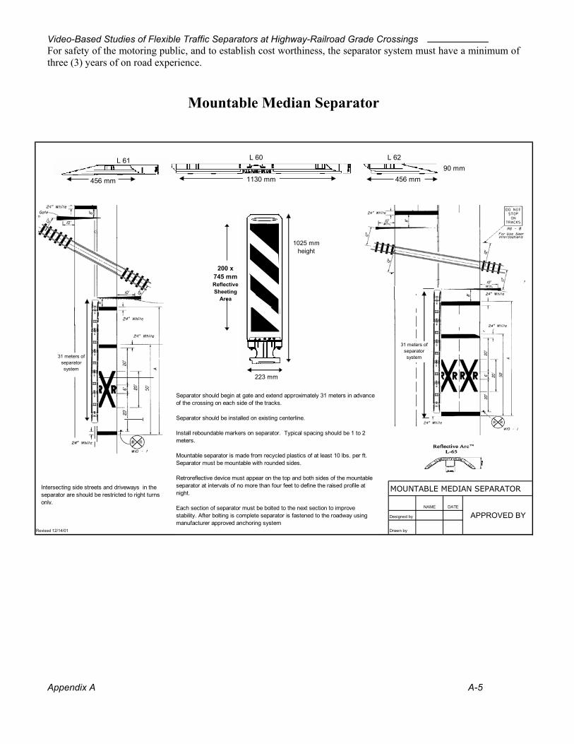
Video-Based Studies of Flexible Traffic Separators at Highway-Railroad Grade Crossings
Appendix A A-5
For safety of the motoring public, and to establish cost worthiness, the separator system must have a minimum of three (3) years of on road experience.
Mountable Median Separator
456 mm
TYPICAL MARKERS
MOUNTABLE MEDIAN SEPARATOR
NAME DATE
Designed by APPROVED BY
Revised 12/14/01 Drawn by
L 61 L 60 L 62
Separator should begin at gate and extend approximately 31 meters in advance of the crossing on each side of the tracks.
Separator should be installed on existing centerline.
Install reboundable markers on separator. Typical spacing should be 1 to 2 meters. Mountable separator is made from recycled plastics of at least 10 lbs. per ft. Separator must be mountable with rounded sides.
Retroreflective device must appear on the top and both sides of the mountable separator at intervals of no more than four feet to define the raised profile at night.
Each section of separator must be bolted to the next section to improve stability. After bolting is complete separator is fastened to the roadway using manufacturer approved anchoring system
1130 mm
200 x 745 mmReflective Sheeting
Area
1025 mmheight
223 mm
Intersecting side streets and driveways in the separator are should be restricted to right turns only.
31 meters of separator system31 meters of
separator system
456 mm90 mm
456 mm

Video-Based Studies of Flexible Traffic Separators at Highway-Railroad Grade Crossings
Appendix A A-6
HOBO® H6 State Logger Measure: State open/closed The HOBO H6 State logger records when devices change between open and closed, storing the time, date, and state for each change. Black arrows in diagram show when data is recorded. Use your PC to readout and analyze the data. Features and specifications
• Capacity: 2000 state changes • Time resolution: 0.5 second • Minimum state duration: 0.5 second • Readout and relaunch with optional HOBO Shuttle • Drop-proof to 5 feet • Mounting kit included (hook/loop, magnet, and tape) • Programmable start time/date • Memory modes: stop when full, wrap-around when full • Nonvolatile EEPROM memory retains data even if battery fails • Blinking LED lights show current state • User-replaceable battery lasts one year • Battery check at launch • Operating range: -4°F to +158°F (-20°C to +70°C), 0 to 95% relative humidity, non-condensing, non-fogging • Time accuracy: ±1 minute per week at +68°F (+20°C) • Size/Weight: 2.4 x 1.9 x 0.8" (60 x 48 x 19mm)/approx. 1 oz. (29 gms) • One year warranty
State Model Specifications Open/closed, contract closure
• Two inputs: a magnetic sensor mounted in the logger and an external input cable for detecting contact closures. • Spacing between HOBO State and external magnet: closed < 1/4"; open > 3/4" (external magnet included). • External contact input: passive relay switch or contact closure.

Video-Based Studies of Flexible Traffic Separators at Highway-Railroad Grade Crossings
APPENDIX B
FLORIDA LAWS RELATED TO HIGHWAY-RAILROAD GRADE CROSSINGS

Video-Based Studies of Flexible Traffic Separators at Highway-Railroad Grade Crossings
Appendix B B-1
Title XXIII
Motor Vehicles Chapter 316
State Uniform Traffic Control
316.1575 Obedience to traffic control devices at railroad-highway grade crossings.--
(1) Any person walking or driving a vehicle and approaching a railroad-highway grade crossing under any of the circumstances stated in this section shall stop within 50 feet but notless than 15 feet from the nearest rail of such railroad and shall not proceed until he or she cando so safely. The foregoing requirements apply when:
(a) A clearly visible electric or mechanical signal device gives warning of the immediateapproach of a railroad train;
(b) A crossing gate is lowered or a human flagger gives or continues to give a signal of theapproach or passage of a railroad train;
(c) An approaching railroad train emits an audible signal or the railroad train, by reason of itsspeed or nearness to the crossing, is an immediate hazard; or
(d) An approaching railroad train is plainly visible and is in hazardous proximity to therailroad-highway grade crossing, regardless of the type of traffic control devices installed atthe crossing.
(2) No person shall drive any vehicle through, around, or under any crossing gate or barrierat a railroad-highway grade crossing while the gate or barrier is closed or is being opened orclosed.
(3) A violation of this section is a noncriminal traffic infraction, punishable pursuant to chapter 318 as either a pedestrian violation or, if the infraction resulted from the operation ofa vehicle, as a moving violation.

Video-Based Studies of Flexible Traffic Separators at Highway-Railroad Grade Crossings
Appendix B B-2
Title XXIII
Motor Vehicles Chapter 316
State Uniform Traffic Control
316.1945 Stopping, standing, or parking prohibited in specified places.--
(1) Except when necessary to avoid conflict with other traffic, or in compliance with law orthe directions of a police officer or official traffic control device, no person shall:
(a) Stop, stand, or park a vehicle:
8. On any railroad tracks.
(c) Park a vehicle, whether occupied or not, except temporarily for the purpose of, and whileactually engaged in, loading or unloading merchandise or passengers:
1. Within 50 feet of the nearest rail of a railroad crossing unless the Department ofTransportation establishes a different distance due to unusual circumstances.
(4) A violation of this section is a noncriminal traffic infraction, punishable as a nonmovingviolation as provided in chapter 318.
Title XXIII Motor Vehicles
Chapter 316 State Uniform Traffic Control
316.183 Unlawful speed.--
(1) No person shall drive a vehicle on a highway at a speed greater than is reasonable andprudent under the conditions and having regard to the actual and potential hazards thenexisting. In every event, speed shall be controlled as may be necessary to avoid colliding withany person, vehicle, or other conveyance or object on or entering the highway in compliancewith legal requirements and the duty of all persons to use due care.
(4) The driver of every vehicle shall, consistent with the requirements of subsection (1), driveat an appropriately reduced speed when:
(a) Approaching and crossing an intersection or railway grade crossing;
(7) A violation of this section is a noncriminal traffic infraction, punishable as a moving violation as provided in chapter 318.

Video-Based Studies of Flexible Traffic Separators at Highway-Railroad Grade Crossings
Appendix B B-3
Title XXIII
Motor Vehicles Chapter 316
State Uniform Traffic Control
316.170 Moving heavy equipment at railroad grade crossings.--
(1) No person shall operate or move any crawler-type tractor, steam shovel, derrick, or roller, or any equipment or structure having a normal operating speed of 10 or less miles per hour ora vertical body or load clearance of less than 1/2 inch per foot of the distance between anytwo adjacent axles or in any event of less than 9 inches, measured above the level surface of aroadway, upon or across any tracks at a railroad grade crossing without first complying with this section.
(2) Notice of any such intended crossing shall be given to a station agent or other properauthority of the railroad, and a reasonable time shall be given to the railroad to provide properprotection at the crossing.
(3) Before making any such crossing the person operating or moving any such vehicle orequipment shall first stop the same not less than 15 feet nor more than 50 feet from thenearest rail of the railroad and while so stopped shall listen and look in both directions along the track for any approaching train and for signals indicating the approach of a train, and shallnot proceed until the crossing can be made safely.
(4) No such crossing shall be made when warning is being given by automatic signal orcrossing gates or a flagger or otherwise of the immediate approach of a railroad train or car. Ifa flagger is provided by the railroad, movement over the crossing shall be under his or herdirection.
(5) A violation of this section is a noncriminal traffic infraction, punishable as a moving violation as provided in chapter 318.

Video-Based Studies of Flexible Traffic Separators at Highway-Railroad Grade Crossings
Appendix B B-4
Title XXIII
Motor Vehicles Chapter 316
State Uniform Traffic Control
316.159 Certain vehicles to stop at all railroad grade crossings.--
(1) The driver of any motor vehicle carrying passengers for hire, excluding taxicabs, of anyschool bus carrying any school child, or of any vehicle carrying explosive substances orflammable liquids as a cargo or part of a cargo, before crossing at grade any track or tracks ofa railroad, shall stop such vehicle within 50 feet but not less than 15 feet from the nearest railof the railroad and, while so stopped, shall listen and look in both directions along the track for any approaching train, and for signals indicating the approach of a train, except ashereinafter provided, and shall not proceed until he or she can do so safely. After stopping asrequired herein and upon proceeding when it is safe to do so, the driver of any such vehicle shall cross only in a gear of the vehicle so that there will be no necessity for changing gearswhile traversing the crossing, and the driver shall not shift gears while crossing the track ortracks.
(2) No stop need be made at any such crossing where a police officer, a traffic control signal,or a sign directs traffic to proceed. However, any school bus carrying any school child shallbe required to stop unless directed to proceed by a police officer.
(3) A violation of this section is a noncriminal traffic infraction, punishable as a movingviolation as provided in chapter 318.
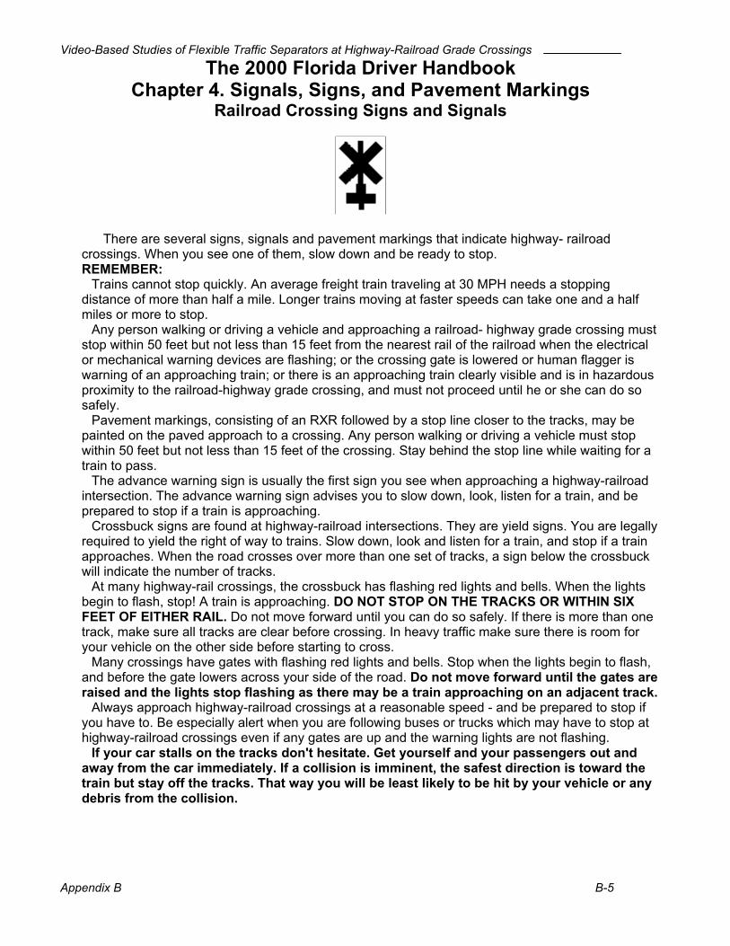
Video-Based Studies of Flexible Traffic Separators at Highway-Railroad Grade Crossings
Appendix B B-5
The 2000 Florida Driver Handbook Chapter 4. Signals, Signs, and Pavement Markings
Railroad Crossing Signs and Signals
There are several signs, signals and pavement markings that indicate highway- railroad crossings. When you see one of them, slow down and be ready to stop. REMEMBER:
Trains cannot stop quickly. An average freight train traveling at 30 MPH needs a stopping distance of more than half a mile. Longer trains moving at faster speeds can take one and a half miles or more to stop.
Any person walking or driving a vehicle and approaching a railroad- highway grade crossing must stop within 50 feet but not less than 15 feet from the nearest rail of the railroad when the electrical or mechanical warning devices are flashing; or the crossing gate is lowered or human flagger is warning of an approaching train; or there is an approaching train clearly visible and is in hazardous proximity to the railroad-highway grade crossing, and must not proceed until he or she can do so safely.
Pavement markings, consisting of an RXR followed by a stop line closer to the tracks, may be painted on the paved approach to a crossing. Any person walking or driving a vehicle must stop within 50 feet but not less than 15 feet of the crossing. Stay behind the stop line while waiting for a train to pass.
The advance warning sign is usually the first sign you see when approaching a highway-railroad intersection. The advance warning sign advises you to slow down, look, listen for a train, and be prepared to stop if a train is approaching.
Crossbuck signs are found at highway-railroad intersections. They are yield signs. You are legally required to yield the right of way to trains. Slow down, look and listen for a train, and stop if a train approaches. When the road crosses over more than one set of tracks, a sign below the crossbuck will indicate the number of tracks.
At many highway-rail crossings, the crossbuck has flashing red lights and bells. When the lights begin to flash, stop! A train is approaching. DO NOT STOP ON THE TRACKS OR WITHIN SIX FEET OF EITHER RAIL. Do not move forward until you can do so safely. If there is more than one track, make sure all tracks are clear before crossing. In heavy traffic make sure there is room for your vehicle on the other side before starting to cross.
Many crossings have gates with flashing red lights and bells. Stop when the lights begin to flash, and before the gate lowers across your side of the road. Do not move forward until the gates are raised and the lights stop flashing as there may be a train approaching on an adjacent track.
Always approach highway-railroad crossings at a reasonable speed - and be prepared to stop if you have to. Be especially alert when you are following buses or trucks which may have to stop at highway-railroad crossings even if any gates are up and the warning lights are not flashing.
If your car stalls on the tracks don't hesitate. Get yourself and your passengers out and away from the car immediately. If a collision is imminent, the safest direction is toward the train but stay off the tracks. That way you will be least likely to be hit by your vehicle or any debris from the collision.

Video-Based Studies of Flexible Traffic Separators at Highway-Railroad Grade Crossings
APPENDIX C
CAPTURED VIDEO EVENTS

Video-Based Studies of Flexible Traffic Separators at Highway-Railroad Grade Crossings
SECONDS RELATIVE TO GATES DOWN OR TRAIN DEPARTURE
BEFORE TRAIN AFTER TRAIN STUDY
SITE VIOLATION NUMBER
VEHICLE TYPE
VEHICLE DIRECTION
TRAIN ARRIVED?
ARRIVAL VIOLATION ARRIVAL VIOLATION
WARNING TIME (SEC)
PARK 1 car north yes when train stopped 7
PARK 2 car north yes 5 29
PARK 3 bicycle south yes 5 27
PARK 4 bicycle south yes 6 27
PARK 5 bicycle south yes 27
SR 17 1 car northeast no -15 98
SR 17 2 car southwest no -6 118
SR 17 3 car northeast no 109
SR 17 4 car northeast no 125
SR 17 5 car northeast no 129
SR 17 6 car northeast no 140
SR 17 7 car northeast no 160
SR 17 8 car southwest yes 43 76
SR 17 9 car southwest yes 3 24 72
SR 17 10 car southwest yes before flasher 446
SR 17 11 car southwest no 54 58
SR 17 12 car northeast no 0 6
SR 17 13 car southwest yes -1 11 47
SR 17 14 car northeast yes -1 31
SR 17 15 pedestrian northeast yes -8 3 63
SR 17 16 car southwest yes -1 8 48
SR 17 17 car southwest yes 2 45
SR 17 18 car northeast yes 3 31
US 98 1 pedestrian eastbound yes 39 42 98
US 98 2 car westbound yes 34 45 161
US 98 3 car eastbound yes 14 27 73
US 98 4 car eastbound yes 30 35 73
US 98 5 car eastbound yes -4 2 45
US 98 6 car westbound yes 0 11 56
US 98 7 car westbound yes 33 38
Appendix C C-1
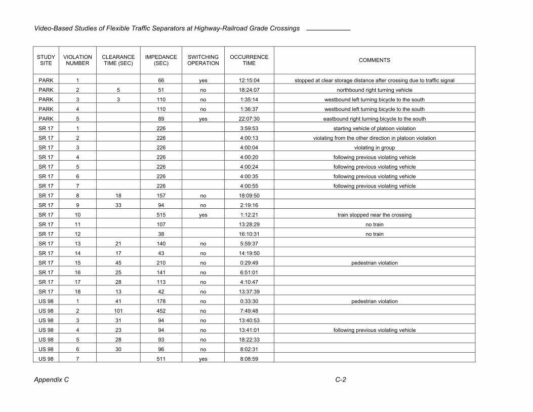
Video-Based Studies of Flexible Traffic Separators at Highway-Railroad Grade Crossings
STUDY
SITE VIOLATION NUMBER
CLEARANCE TIME (SEC)
IMPEDANCE (SEC)
SWITCHING OPERATION
OCCURRENCE TIME COMMENTS
PARK 1 66 yes 12:15:04 stopped at clear storage distance after crossing due to traffic signal
PARK 2 5 51 no 18:24:07 northbound right turning vehicle
PARK 3 3 110 no 1:35:14 westbound left turning bicycle to the south
PARK 4 110 no 1:36:37 westbound left turning bicycle to the south
PARK 5 89 yes 22:07:30 eastbound right turning bicycle to the south
SR 17 1 226 3:59:53 starting vehicle of platoon violation
SR 17 2 226 4:00:13 violating from the other direction in platoon violation
SR 17 3 226 4:00:04 violating in group
SR 17 4 226 4:00:20 following previous violating vehicle
SR 17 5 226 4:00:24 following previous violating vehicle
SR 17 6 226 4:00:35 following previous violating vehicle
SR 17 7 226 4:00:55 following previous violating vehicle
SR 17 8 18 157 no 18:09:50
SR 17 9 33 94 no 2:19:16
SR 17 10 515 yes 1:12:21 train stopped near the crossing
SR 17 11 107 13:28:29 no train
SR 17 12 38 16:10:31 no train
SR 17 13 21 140 no 5:59:37
SR 17 14 17 43 no 14:19:50
SR 17 15 45 210 no 0:29:49 pedestrian violation
SR 17 16 25 141 no 6:51:01
SR 17 17 28 113 no 4:10:47
SR 17 18 13 42 no 13:37:39
US 98 1 41 178 no 0:33:30 pedestrian violation
US 98 2 101 452 no 7:49:48
US 98 3 31 94 no 13:40:53
US 98 4 23 94 no 13:41:01 following previous violating vehicle
US 98 5 28 93 no 18:22:33
US 98 6 30 96 no 8:02:31
US 98 7 511 yes 8:08:59
Appendix C C-2

Video-Based Studies of Flexible Traffic Separators at Highway-Railroad Grade Crossings
Appendix C C-1
Park Road
Violation 1
Violation 2
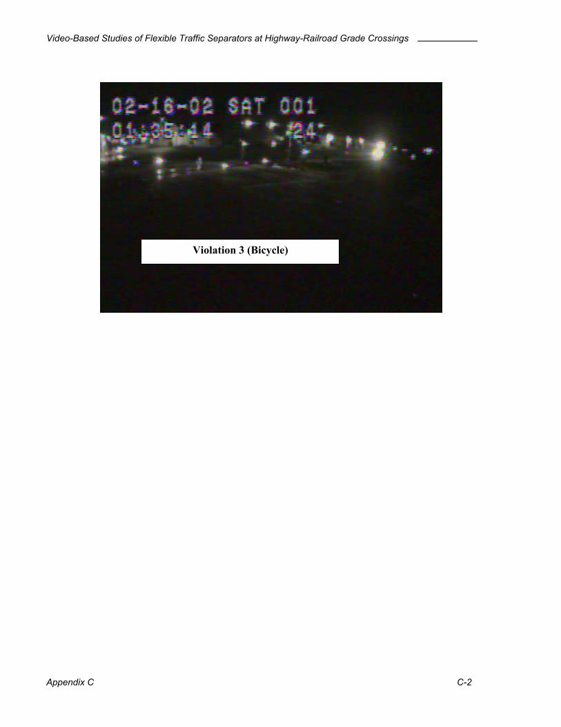
Video-Based Studies of Flexible Traffic Separators at Highway-Railroad Grade Crossings
Appendix C C-2
Violation 3 (Bicycle)

Video-Based Studies of Flexible Traffic Separators at Highway-Railroad Grade Crossings
Appendix C C-3
US 98
Violation 1 (pedestrian)
Violation 2
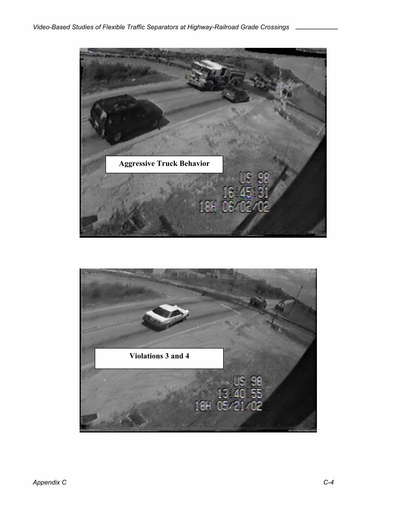
Video-Based Studies of Flexible Traffic Separators at Highway-Railroad Grade Crossings
Appendix C C-4
Aggressive Truck Behavior
Violations 3 and 4

Video-Based Studies of Flexible Traffic Separators at Highway-Railroad Grade Crossings
Appendix C C-5
Violation 5
Violation 6

Video-Based Studies of Flexible Traffic Separators at Highway-Railroad Grade Crossings
Appendix C C-6
Violation 7
Pedestrian was later killed walking down the tracks
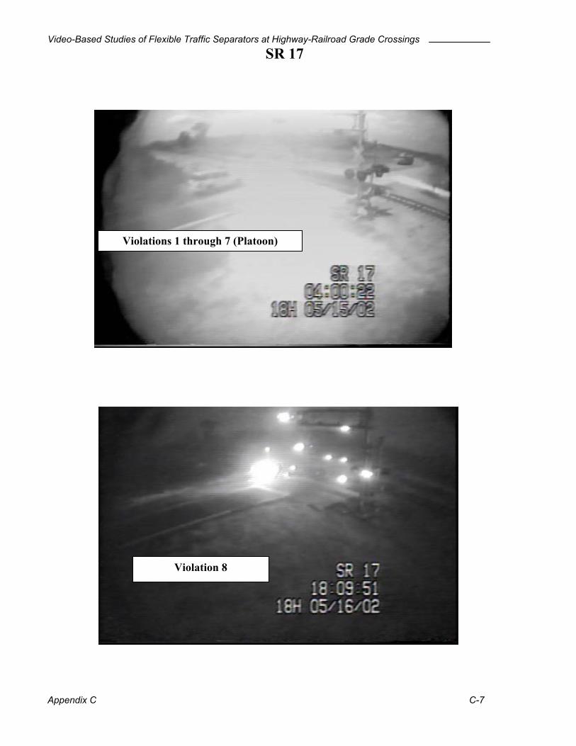
Video-Based Studies of Flexible Traffic Separators at Highway-Railroad Grade Crossings
Appendix C
SR 17
Violations 1 through 7 (Platoon)C-7
Violation 8
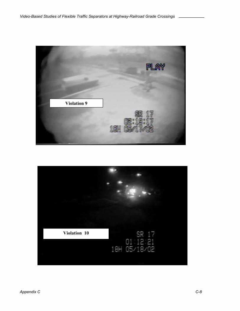
Video-Based Studies of Flexible Traffic Separators at Highway-Railroad Grade Crossings
Appendix C C-8
Violation 9
Violation 10
Video-Based Studies of Flexible Traffic Separators at Highway-Railroad Grade Crossings
Appendix C C-9
Violation 11
Violation 12

Video-Based Studies of Flexible Traffic Separators at Highway-Railroad Grade Crossings
Appendix C C-10
Violation 13
Violation 14
Video-Based Studies of Flexible Traffic Separators at Highway-Railroad Grade Crossings
Appendix C C-11
Violation 15
Violation 16
Video-Based Studies of Flexible Traffic Separators at Highway-Railroad Grade Crossings
Appendix C C-12
Violation 17

Video-Based Studies of Flexible Traffic Separators at Highway-Railroad Grade Crossings
APPENDIX D
DATA ANALYSIS SPREADSHEETS
(Delivered Separately on CD-ROM)