Embed Size (px)
Citation preview

TRANSPORT WINGS
History, Notes andInstructions
1:72 Mixed-media conversion pack
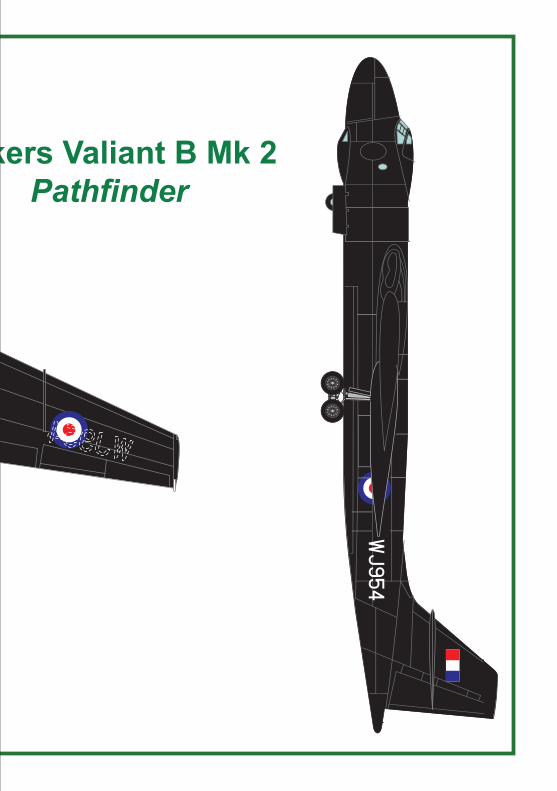
Vickers Valiant B Mk. 2‘Pathfinder’
Copyright unknown
The Black Bomber

History
Description of this Conversion Pack
Parts List
RESIN PARTS
METAL PARTS
MISCELLANEOUS
A development of the B.Mk.1, the Vickers Valiant B.Mk.2 was intended as a pathfinder to mark targets for the main bomber force, to reach its targets by flying at low level and high speed to avoid detection. This involved strengthening the airframe by replacing the landing gear bays of the B.Mk.1 with wing fairings that housed the re-designed, rear retracting four-wheel bogie landing gear. The Valiant B.Mk.2 design also introduced a forward fuselage extension plug that provided additional avionics and balancing the new (aft) position of the main landing gear.The prototype B Mk.2, serial number WJ954 first flew on 4 September 1953, after the order for Valiant B Mk.2 aircraft had already been cancelled. Finished in a gloss black night operations paint scheme, it became known as the "Black Bomber". Its performance at low level was superior to that of the B Mk.1 .Ironically when the Valiant B Mk.1s were operated at low level it caused fatigue in the structure and by 1965 the Valiant fleet had been scrapped.
This conversion pack is for use with the Airfix Valiant B Mk.1 kit and consists of resin parts for the fuselage plug and two landing gear pods, together with cast metal main landing gear units and landing gear bay doors. Alps printed white serial number decals are supplied (roundels and fin flashes come from the decal sheet in the kit).The conversion is in two parts, the fuselage and the wings, and is suitable for the experienced modeller.
Fuselage plug (left) . . . . . . . . . . . . . . . . . . . . . . . . . . . . . . . . 1 offFuselage plug (right) . . . . . . . . . . . . . . . . . . . . . . . . . . . . . . . 1 offLanding gear pod . . . . . . . . . . . . . . . . . . . . . . . . . . . . . . . . . 2 off
Bellcrank & linkage (left) . . . . . . . . . . . . . . . . . . . . . . . . . . . . 2 offBellcrank & linkage (right) . . . . . . . . . . . . . . . . . . . . . . . . . . . 2 offLanding gear door - front. . . . . . . . . . . . . . . . . . . . . . . . . . . . 2 offLanding gear door - left . . . . . . . . . . . . . . . . . . . . . . . . . . . . . 2 offLanding gear door - right . . . . . . . . . . . . . . . . . . . . . . . . . . . . 2 offLevelling cylinder. . . . . . . . . . . . . . . . . . . . . . . . . . . . . . . . . . 4 offMain landing gear leg . . . . . . . . . . . . . . . . . . . . . . . . . . . . . . 2 offMain wheel - left . . . . . . . . . . . . . . . . . . . . . . . . . . . . . . . . . . 4 offMain wheel - righ) . . . . . . . . . . . . . . . . . . . . . . . . . . . . . . . . . 4 offRetraction jack. . . . . . . . . . . . . . . . . . . . . . . . . . . . . . . . . . . . 2 offTie rod . . . . . . . . . . . . . . . . . . . . . . . . . . . . . . . . . . . . . . . . . . 4 off
Decal sheet - serial numbers (microdry printer printed) . . . . 4 offInstructions . . . . . . . . . . . . . . . . . . . . . . . . . . . . . . . . . . . . . . 1 set

1 GENERAL
WARNINGS 1 - THIS KIT CONTAINS SMALL AND/OR SHARP PARTS. KEEP THE CONTENTS OF THE KIT AWAY FROM CHILDREN.
2 - THIS KIT CAN CONTAIN PRECUT PARTS WITH SHARP EDGES OR CORNERS. BE CAREFUL WHEN YOU HANDLE THESE PARTS BECAUSE THEY CAN CAUSE CUTS OR OTHER INJURIES.
3 - USE ALL SOLVENTS, PAINTS, FILLERS AND OTHER MATERIAL IN ACCORDANCE WITH THE MANUFACTURER’S INSTRUCTION. OBEY ALL SAFETY WARNINGS.
2 FUSELAGEA Cut the fuselage halves as shown in Figure 1. It is
important to position this cut accurately, because the hinge lugs of each nose landing gear door fit in one slot on the fuselage and two slots in the fuselage plug. If the position of the cut is not completely accurate, you can widen the slots in the plug to accept the lugs of the nose landing gear doors.
Figure 1
FORWARD EDGE OFNOSE LANDING
GEAR BAY(DATUM)
CUT HERE
CUT HERE
DISCARD THIS PIECE -USE FUSELAGE PLUG
AS TEMPLATE FOR SIZE AND SHAPE
ASECTION A-A
A
LC
11mmREF
18.25mm
18.25mm21.6mm 57.2mm

B Assemble the nose portion of the fuselage as detailed in the kit instructions, so that the forward fuselage and cockpit are complete. Do not attach the transparencies at this time to protect them from scratches. Attach the nose landing gear bay to the forward fuselage.
C Cut the rectangular section from the lower rear fuselage as shown in figure 1, and to the width shown in Section A-A of Figure 1.
D Assemble the remainder of the kit in accordance with the kit instructions, with these variations from the instructions:– Assemble the main landing gear doors in the
closed position.– When the jet pipes are securely attached, trim
them so that only 1.5mm projects from the fairings.
– Do not attach the flying controls, bomb bay doors or other detail parts.
E Make sure that the mating faces of the two halves of the fuselage plug are flat, then assemble them with epoxy cement (see Figure 2).
Figure 2F Fit the fuselage plug into the forward and rear fuselage
sections as shown in figure 3 . Make sure that:– The plug is symmetrical with the two fuselage
halves.
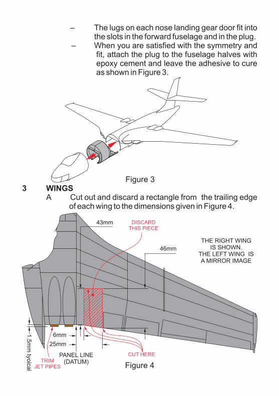
– The lugs on each nose landing gear door fit into the slots in the forward fuselage and in the plug.
– When you are satisfied with the symmetry and fit, attach the plug to the fuselage halves with epoxy cement and leave the adhesive to cure as shown in Figure 3.
Figure 3
3 WINGSA Cut out and discard a rectangle from the trailing edge
of each wing to the dimensions given in Figure 4.
Figure 4
PANEL LINE(DATUM)
THE RIGHT WINGIS SHOWN.
THE LEFT WING ISA MIRROR IMAGE
6mm1.5
mm
tyoica
l
25mm
43mm
46mm
CUT HERETRIM
JET PIPES
DISCARDTHIS PIECE

Vickers Valiant B Mk 2Pathfinder
Aircraft In Miniature Ltd - © 2016Initial issue - 18 August 2016
Vickers Valiant B Mk 2Pathfinder

B Trim the cutout in each wing until each landing gear pod fits well and aligns accurately as shown in the drawing in the centre of these instructions.
C Attach each landing gear pod to the airframe as shown in Figure 5 with epoxy cement. Make sure that it is accurately aligned and leave the assembly until the cement has cured.
D Trim the four jetpipes to approximately 1.5mm projection from the trailing edge of the wing as shown in Figure 4.
Figure 54 LANDING GEAR - see Figure 6
A Attach the parts of each main landing gear with epoxy cement or cyanoacrylates (super glue).
B Left main landing gear assembly - see Figure 6(1) Attach one levelling cylinder (6) to each side of
the bogie beam of a main landing gear leg (1). The attachment end of each levelling cylinder touches a small pin at the forward end of the bogie beam.
(2) Attach a left bellcrank and linkage (4) to the main landing gear leg (1). The linkage is horizontal and the bellcrank is vertical and the

linkage attaches to the to the knuckle of the leg. The lower end of the bellcrank touchs the jack
bellcrank and linkage (4) to the main landing gear leg (1). The linkage is horizontal and the bellcrank is vertical and the linkage attaches to the to the knuckle of the leg. The lower end of the bellcrank touchs the jack of the levelling cylinder.
Note - Each bellcrank and linkage has surface detail on the visible face and a flat inner face for mounting.
(3) Do step 3B(2) again and attach a right bellcrank and linkage (7).
(4) Attach two left main wheels (5) to the bogie beam.
Figure 6
(2) Attach a left
The main wheels are handed so that the brake cylinders are positioned forward of the axle and the wheels have a very small socket which aligns with a pin on the bogie beam.
2 - REF
4
5
56
6
3
File here to match the contour
of the trunnion (typical)
Bogie beam
Filetrunnions
here to suit
the width of the pod(file both
ends equally)
78
8
3
1

(5)
File the end of each tie rod so that it matches the contour of the trunnion before you attach it.
C Install the main landing gear assemblies.(1) When the left main landing gear assembly is
complete, file the ends of the trunnions (see Figure 6) to give a smooth fit into the landing gear pod.
Figure 7(2) Fit the landing gear assembly (2) in to the pod
(1) - see Figure 7. The trunnions fit into recesses at each side of the pod. Attach the
Do step 3B(4) again and attach two right main wheels (8).
(6) Attach two tie rods (3) between the link of each bellcrank and the linkage of bellcrank and linkages (4) and (7) and the underside of the trunnion of the main landing gear leg (1).
BOND AREA2
3
1
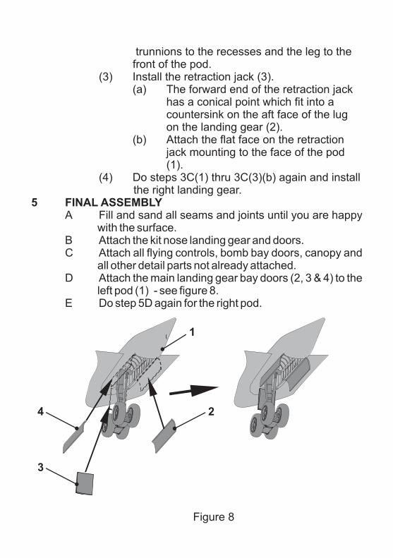
trunnions to the recesses and the leg to the front of the pod.
(3) Install the retraction jack (3). (a) The forward end of the retraction jack
has a conical point which fit into a countersink on the aft face of the lug on the landing gear (2).
(b) Attach the flat face on the retraction jack mounting to the face of the pod (1).
(4) Do steps 3C(1) thru 3C(3)(b) again and install the right landing gear.
5 FINAL ASSEMBLYA Fill and sand all seams and joints until you are happy
with the surface.B Attach the kit nose landing gear and doors.C Attach all flying controls, bomb bay doors, canopy and
all other detail parts not already attached.D Attach the main landing gear bay doors (2, 3 & 4) to the
left pod (1) - see figure 8.E Do step 5D again for the right pod.
Figure 8
2
1
3
4

6 PAINTING AND FINISHINGA When all the detail parts are attached, degrease,
prime and paint the model gloss black overall.The landing gear and their bays are believed to have been silver or aluminium, while the tyres are matt black.
B Apply the waterslide transfers or decals as shown on the colour scheme drawing. The roundels and fin flashes come from the decal sheet in the Airfix kit and the white serial numbers WJ954 are included in this conversion pack. The serial number decals are microdry printer printed, which are delicate, so apply a coat of protective varnish when the decals have dried.
© Aircraft In Miniature Ltd 2016The manufacturers reserve the right to alter parts; add to, or delete parts without
prior notification in the interests of quality control, production, or product improvement.
Errors And Omissions Excepted.
This kit is manufactured in the United Kingdom by
Aircraft In Miniature Limited19, Watling Street, Nuneaton, Warwickshire, CV11 6JJ, England
Email: [email protected] - Web site: www.aim72.co.uk