Embed Size (px)
Citation preview

Composite Structures 134 (2015) 689–707
Contents lists available at ScienceDirect
Composite Structures
journal homepage: www.elsevier .com/locate /compstruct
Vibro-acoustic analysis of multilayered shells of revolution basedon a general higher-order shear deformable zig-zag theory
http://dx.doi.org/10.1016/j.compstruct.2015.08.0530263-8223/� 2015 Elsevier Ltd. All rights reserved.
⇑ Corresponding author. Tel.: +86 021 34206332; fax: +86 021 34206814.E-mail addresses: [email protected], [email protected] (Y. Qu).
Yegao Qu ⇑, Guang MengState Key Laboratory of Mechanical System and Vibration, Shanghai Jiao Tong University, Shanghai 200240, China
a r t i c l e i n f o
Article history:Available online 24 August 2015
Keywords:Multilayered shellZig-zag theoryFluidVibrationSound radiation
a b s t r a c t
This paper presents a semi-analytical approach for predicting the vibration and acoustic responses of anarbitrarily shaped, multilayered shell of revolution immersed in a light or heavy unbounded fluid. Ahigher-order shear deformable zig-zag shell theory with general shape functions is proposed to describethe displacement field of a multilayered shell with arbitrary curvatures, which provides a theoretical uni-fication of most thin and shear deformable shell theories in the literature. Based on the higher-order zig-zag theory, the structure model of the multilayered shell is formulated by using a modified variationalmethod combined with a multi-segment technique, whereas a Chebyshev spectral Kirchhoff–Helmholtz integral formulation is employed to model the exterior acoustic fluid. The displacement fieldof the shell and the sound pressure of the fluid are expanded by Fourier series and Chebyshev orthogonalpolynomials. Such a treatment reduces the size of the problem and permits a semi-analytical solution forthe displacement and acoustic variables. A set of collocation nodes distributed over the roots ofChebyshev polynomials are used to establish the algebraic system of the acoustic integral equations,and the non-uniqueness solution is eliminated by means of interior CHIEF points. Numerical examplesare given for vibration and acoustic radiation analyses of multilayered spherical, cylindrical and conicalshells. Comparison studies are performed to evaluate the accuracy of various shell theories. The validityof the present method for acoustic analyses of multilayered shells is demonstrated by comparing theresults with exact solutions and those obtained from the coupled finite element/boundary elementmethod. Individual contributions of circumferential modes to the radiated sound of multilayered shellsare examined.
� 2015 Elsevier Ltd. All rights reserved.
1. Introduction
Multilayered composite shells are increasingly used asadvanced structural elements in aerospace, automotive, militaryand marine industries due to their material merits and structuralefficiencies. Missiles, rockets, torpedoes and submarines are exam-ples of the use of such shells in aerospace and marine engineering.In many of these fields, the radiated noise due to structural vibra-tion presents a very important problem, and therefore the predic-tion and control of acoustic radiation from multilayered compositeshells are of great interest. Though the last few decades have seentremendous progress in the analysis of structure-borne soundproblems, an accurate prediction of the vibration and acousticbehaviors of multilayered composite shells still remains a chal-lenging task. This is primarily because of the intrinsically anisotro-pic and heterogeneous properties of the shells as well as the
complex structure-fluid interaction involved in an acoustic prob-lem. The main concern of this paper is to establish a generalmethod for the vibration and acoustic analyses of an arbitrarilyshaped, multilayered composite shell of revolution immersed in alight or heavy fluid of infinite extent.
An appropriate multilayered shell theory forms the basis of areliable assessment on the vibration and sound radiation of multi-layered composite shells. The development of accurate laminatedshell theories has been one of the most prominent challenges insolid mechanics for many years. Numerous shell theories basedon different approximations and hypotheses have been proposed.Physically, a multilayered shell of revolution is a three-dimensional (3-D) body, and therefore the methods of the exact3-D theory of elasticity can be applied [1]. However, the governingequations of the 3-D elasticity theory for multilayered shells arerather complex when written in natural curvilinear shell coordi-nates, and moreover, the related computation based on the elastic-ity theory is quite cumbersome and inefficient. Consequently,researchers make simplifying assumptions and reduce the 3-D

690 Y. Qu, G. Meng / Composite Structures 134 (2015) 689–707
shell problems to various 2-D representations with reasonableaccuracy. Notable among them are the classical shell theories(CSTs), first-order shear deformable shell theories (FSDTs),higher-order shear deformable shell theories (HSDTs), zig-zag the-ories (ZZT) and the layer-wise (LW) models. A comprehensivereview of these theories is provided by Carrera [2,3], Toorani andLakis [4], Noor and Burton [5] and Qatu et al. [6,7]. The CSTs arebased on the Love-Kirchhoff hypotheses and neglect the transversenormal and shear deformations of multilayered shells. These theo-ries can be grossly in error for predicting the vibration behaviors ofmultilayered shells made of advanced filamentary compositematerials, e.g., graphite-epoxy, which are susceptible to thicknesseffects because their effective transverse shear moduli are signifi-cantly smaller than the effective elastic modulus along the fiberdirection. Depending on different assumptions made during thederivation of the kinematic equations, constitutive relations andthe equilibrium equations, a number of CSTs have been developed,historically, within the Love-Kirchhoff framework, such as Don-nell’s, Love’s, Reissner’s, Novozhilov’s, Vlasov’s, Sanders’, andFlügge’s thin shell theories [8]. Koiter [9] pointed out that therefinement of Love’s approximation for thin shells is meaninglessunless the effects of transverse shear and normal stresses are takeninto account. For moderately thick composite shells, the transversenormal stress is negligible compared to the transverse shear stres-ses [10]. The consideration of the effects of transverse shear defor-mations of shells leads to various FSDTs [4,11,12] and HSDTs[10,13–16]. Constant transverse shear strains in the shell thicknessare assumed in FSDTs, and shear correction factors have to beincorporated in FSDTs to adjust the transverse shear stiffness ofthe shell. FSDTs account for nonlinear distribution of shear stressesthrough shell thickness, and most of these theories satisfy the con-ditions of zero transverse shear stresses on the top and bottom sur-faces of the shell. Consequently, there is no need to use shearcorrection factors in HSDTs.
Physically, a multilayered composite shell exhibits a piece-wisecontinuous displacement field in its thickness direction. Thechange in slope of the displacement fields of two adjacent layersis known as the zig-zag (ZZ) effect [2,3,17–20]. All the previouslymentioned CSTs, FSDTs and HSDTs are not able to reproduce piece-wise continuous displacement and transverse stress fields in theshell thickness direction, which are intrinsically experienced bymultilayered shells. Refined models labeled as ZZTs have beendeveloped in order to take the ZZ effect into account. Possibilitiesto consider the ZZ effect for a multilayered composite shell canbe made in CSTs, FSDTs, HSDTs and LW models [2,3,20]. Compre-hensive numerical studies [3,20] reveal that ZZTs are accurate forthe prediction of global behaviors of multilayered shells and givereliable results compared well with the exact elasticity solution.With regard to the LW models [21–24], each layer in a multilay-ered shell is considered as a shell, for which a separate displace-ment field is assumed, thus providing a kinematically correctrepresentation of the displacement field in discrete layers. TheseLW models are very accurate in predicting the global–localresponses of multilayered composite shells. However, they arecomputationally expensive because the number of unknownsdepend on the number of layers in a multilayered shell.
The literature concerning the structure-borne sound of multi-layered shells is very limited, though considerable attention hasbeen paid to the acoustic problems of homogeneous isotropicshells made of conventional metal materials. For the acoustic anal-ysis of a multilayered shell, the radiated sound is directly coupledwith the vibration of the shell. However, the coupling is character-ized by the strength of the influence between the shell and theacoustic field. From a computational point of view, the structuraland the acoustic problems of a multilayered shell may be solvedsubsequently one after the other when a high acoustic impedance
mismatch exists between the shell and fluid. However, this is notthe case for a shell submerged in a heavy fluid (e.g., water), wherea strong coupling scheme must be applied and the structural andacoustic problems have to be solved simultaneously. Analyticalsolutions to the acoustic radiation problems of multilayered shellsare restricted to spherical and cylindrical shells, for which the clas-sical method of separation of variables for wave equations is avail-able (see [25] for more details). Harari and Sandman [26] used theanalytical method for the vibration and acoustic analyses of athree-layered cylindrical shell, in which the thin shell theoryassumptions were employed for the inner and outer face layersand the first-order shear deformable theory was used to describethe displacement filed of the core. Yin et al. [27] carried out an ana-lytical analysis for the sound radiation from a point-driven, infinitecomposite cylindrical shell based on a thin shell theory. Daneshjouet al. [28] examined the sound transmission through an infinitecomposite cylindrical shell, which is immersed in an external fluidmedium and contains an internal fluid. Cao et al. [29] predicted theradiation of sound from composite cylindrical shells with initialaxial loadings and doubly periodic rings. It is noted that that mul-tilayered shells in engineering applications may not match truespherical and cylindrical configurations. Even when they do, theimplementation of the analytical method is very cumbersomeand tedious because of the complexity of the cylindrical and spher-oidal wave functions. Moreover, the successful implementation ofthe analytical method may also be restricted to the type of externalexciting forces and boundary conditions of the shell. Thus, numer-ical methods are more desirable than the analytical method for thevibration and acoustic analyses of an arbitrarily shaped multilay-ered shell of revolution subjected to mechanical excitation forcesand boundary conditions of arbitrary types.
Considerable effort has been devoted to the development of var-ious numerical methods for vibro-acoustic analyses of elastic struc-tures. For a detailed review of these methods, the reader may refertoMarburg andNolte [30] and the references therein. Regarding theacoustic analysis of an elastic structure immersed in an aboundedfluid, the coupled finite element/boundary elementmethod is prob-ably the most practical approach, in which the dynamic behavior ofthe structure is described by the finite element method (FEM) andthe boundary elementmethod (BEM) is used to represent the acous-tic loading acting on the structure. The interface conditions imposedon the surface between the structure and the fluid are the continuityof normal velocity and the sound pressure acting as a loading on thestructural surface. The FEM is recognized as a general approxima-tion scheme for complex structures, whereas for the acoustic mod-eling, the BEM has the advantage that all discretization andnumerical approximations are placed on the surface of the struc-ture. Moreover, the outgoing radiation condition at infinity is auto-matically satisfied in the BEM [31] when the fluid is of infiniteextent. For the radiation of sound from elastic shells, 2-D or 3-Dfinite elements and 2-D boundary elements may be used to dis-cretize the shell and the acoustic boundary to achieve reasonablyaccurate results. Such elements have been considered by, to namea few, Everstine and Henderson [32], Jeans and Mathews [33], Chenand Liu [34], Caresta and Kessissoglou [35] and Peters et al. [36,37]for vibro-acoustic analyses of homogeneous isotropic shells. Denliand Sun [38] analyzed the interior and exterior acoustic field of asandwich cylindrical shell using 2-D finite elements and boundaryelements. The main drawback of these elements is that they gener-ally lead to a system of equations with a large number of unknowns,and are not able to offer a clear physical insight into the vibrationand acoustic behaviors of the shells. For the sound radiation of abody of revolution, the pressure of the acoustic filed can beexpanded by Fourier series in the circumferential direction. Such atreatment leads to 1-D semi-analytical boundary elements sinceonly a discretization along the generator line of the body is needed.

Fig. 1. A multilayered composite shell of revolution immersed in unbounded fluid.
Y. Qu, G. Meng / Composite Structures 134 (2015) 689–707 691
This reduction is particularly worthwhile because 1-D semi-analytical boundary elements, in general, are computationallymoreefficient than 2-D boundary elements for acoustic problems, andmoreover they provide great physical insight into the mechanismsresponsible for the radiated noise from fluid-loaded structures.The use of 1-D boundary elements for sound radiation analyses ofaxisymmetric bodies has been examined by Soenarko [39], Kuijperset al. [40], Tsinopoulos et al. [41], Wang et al. [42], Wright et al. [43],Caresta and Kessissoglou [44] and Qu et al. [45]. It is well-knownthat the boundary elements based on the classical Kirchhoff–Helm-holtz integral equation, either in a 2-D or 1-D form, may fail to pro-vide unique solutions for acoustic radiation problems at somecertain frequencies known as fictitious frequencies [31]. These fre-quencies do not correspond to a physical situation and yield mean-ingless peaks in acoustic responses, which can be effectivelyeliminated by using the CHIEF method [46] or the Burton–Millermethod [47].
The literature survey reveals that there have been very fewstudies concerning the sound radiation problems of multilayeredshells with particular geometrical configurations (e.g., cylindricaland spherical shapes), and a general vibro-acoustic analysis foran arbitrarily shaped multilayered shell of revolution does notseem to exist. Moreover, the structure modeling of multilayeredshells for acoustic problems has been mostly restricted to CSTsand FSDTs. More accurate theories, such as ZZTs, have not beenattempted so far. The main objective of this paper is to develop ageneral method for predicting the vibration and acoustic radiationof an arbitrarily shaped multilayered shell of revolution immersedin a light or heavy fluid of infinite extent. First, a general higher-order shear deformable zig-zag shell theory is proposed for thestructural modeling of thin and thick composite laminated shellswith arbitrary curvatures. This theory unifies most of the classicaland shear deformable shell theories available in the literature byintroducing general shape functions into the displacement fieldof the shell. Subsequently, a modified variational method devel-oped by the first author and coworkers [1,48–51] for the dynamicanalyses of shell structures, is employed herein to formulate thestructural model of the multilayered shell of revolution based onthe general higher-order zig-zag thoery. A spectral Kirchhoff–Helmholtz integral formulation is used to model the exterioracoustic fluid. The displacements of the shell and the sound pres-sure of the acoustic field are expanded in the form of a doublemixed series, i.e., Fourier series and Chebyshev orthogonal polyno-mials. In doing so, the surface integrals governing the motion of thefluid are reduced to line integrals along the meridian line of theshell, which drastically reduces the size of the problem and per-mits subsequent semi-analytical solutions of the acoustic variablesat specified points in the fluid. The two systems of equations arecoupled together by substituting the fluid equation set into theshell equation set, and the CHIEF method is employed to removethe non-uniqueness of the solution. Numerical examples are pre-sented for vibration and acoustic radiation problems of multilay-ered spherical, cylindrical and conical shells immersed in air andwater and subjected to different excitation forces.
2. Theory
2.1. Preliminaries
Consider an arbitrarily shaped multilayered composite shell ofrevolution immersed in an unbounded fluid, as illustrated inFig. 1. The shell consists of Nl orthotropic layers of uniform thick-ness, and each of these may exhibit different mechanical proper-ties. The thickness of the kth layer and of the entire shell aredenoted by hk (k ¼ 1;2; . . . ;Nl) and h, respectively. For the sake of
convenience, the undeformed middle surface of the shell isselected as the reference surface S. The material points in the shellare referred to an orthogonal curvilinear coordinate system com-posed of coordinates a1, a2 and 1, where a1 and a2 coincide withthe principal curvature lines of the reference surface S (1 ¼ 0),and 1 is the coordinate normal to S. The external fluid is assumedto be inviscid and compressible.
2.2. General higher-order shear deformable zig-zag shell model
For a multilayered composite shell, we assume that thethickness-direction normal stress at any point of the shell is muchsmaller than any of other stresses at that point and is, therefore,negligible. The displacement field of the shell is presented by thefollowing relationships:
~uiða1;a2;1;tÞ¼ 1þ 1Ri
� �uiða1;a2;tÞþ f ð1Þ 1
Ai
@u3
@ai
þgð1Þ#iða1;a2;tÞþuð1;kÞgiða1;a2;tÞ; i¼1; 2 ð1:aÞ
~u3ða1;a2; 1; tÞ ¼ u3ða1;a2; tÞ ð1:bÞwhere ~u1, ~u2 and ~u3 are the displacement components of an arbi-trary point ða1;a2; 1Þ in the a1, a2 and 1 coordinate directions,respectively. t represents the time variable. u1, u2, u3, #1, #2, g1
and g2 are the generalized displacement components of the middlesurface of the shell, which are independent of coordinate 1. Ri arethe principal radii of curvature of the middle surface. Ai are the sur-face metrics that dictate the geometry of the shell surface. f ð1Þ andgð1Þ are shape functions. uð1; kÞ is a zig-zag function definedaccording to the following formula [17]:
uð1; kÞ ¼ ð�1Þk 2hk
1� 12ð1kþ1 þ 1kÞ
� �� 813
3hkh2
( )ð2Þ
where 1k and 1kþ1 are the bottom and top coordinates of the kthlayer. It is obvious that uð1; kÞ is a piece-wise cubic function ofthe thickness coordinate 1. The existence of uð1; kÞ in Eq. (1)ensures a piece-wise continuous displacement field in the shellthickness and a change in slope of the displacement field betweentwo adjacent layers.
In essence, the expression of Eq. (1) is general as it contains thedisplacement fields of various thin and shear deformable theoriesas particular cases. This is achieved by choosing different shapefunctions f ð1Þ and gð1Þ, when the zig-zag function uð1; kÞ is setto be zero. The displacement fields of classical thin shell theories,
692 Y. Qu, G. Meng / Composite Structures 134 (2015) 689–707
e.g., Donnell’s, Love’s, Reissner’s, Novozhilov’s, Vlasov’s, Sanders’sand Flügge’s shell theories, can be recovered directly from Eq. (1)by setting f ð1Þ ¼ �1 and gð1Þ ¼ 0. For the first-order shear deform-able shell theories, the shape functions can be chosen as: f ð1Þ ¼ 0and gð1Þ ¼ 1. The choice of the shape functions for higher-ordershear deformable shell theories is not unique. In practice, this isbased on the satisfaction of certain mechanical constraints of theproblem considered and, in general, characterizes the degree ofsophistication andaccuracyof the resulting shell theory. Table 1 listsa numberof higher-order shear deformable shell theories in termsofdifferent shape functions gð1Þ, when f ð1Þ is takenas�1. Note someofthe shape functions gð1Þ in Table 1 are initially proposed to describethe displacement fields of elastic beams and plates, which areemployed here for the shell problems. Acronyms are used to expressthese theories in a concise manner, as shown in Table 1. Regardingthe tangential trigonometric function proposed by Mantari et al.[60], HSDT[M2] and HSDT[M3] represent the higher-order sheardeformable shell theories with m ¼ 1=ð5hÞ and m ¼ p=ð2hÞ, respec-tively. Similarly, for the shape functions obtained by Viola et al.[13] and El Meiche et al. [65], HSDT[VE1] and HSDT[VE2] denote thehigher-order shell models with m ¼ 1 and m ¼ 1=½coshðp=2Þ � 1�,respectively, whereas HDT[M5] and HDT[M6] indicate the shell theo-ries when the parameter m is respectively taken as -6 and -7 in thehybrid shape functions proposed by Mantari and Guedes Soares[16].When the zig-zag functionuð1; kÞ is retained in Eq. (1), a seriesof higher-order zig-zag theories may be obtained by using thosehigh-order shape functions defined in Table 1. For the sake of clarity,all zig-zag theories are labeled by using an additional subscript Z inthe acronyms of those shear deformable theories without zig-zigfunctions. For example, HSDTZ represents the first-order sheardeformable zig-zag shell theory, and HSDTZ[KPR] represents ahigher-order zig-zag theory which shares the same shape functiongð1Þ of HSDT[KPR]. The general higher-order zig-zag theory leavesopen possibilities for a posteriori specification of new shape func-tions. All further equations for multilayered shells, such as the kine-matic equations, constitutive relations and the equations of motion,are derived using the general displacement field in Eq. (1) so as toensure the applicability of the present formulation and solutionmethodology to various shell theories.
In the orthogonal curvilinear coordinate system, the normal andshear strains related to the displacement components of the shellare given by (no sum on repeated indices; see [69])
ei ¼ @
@ai
~uiffiffiffiffigi
p� �
þ 1ffiffiffiffigi
pX3k¼1
@ffiffiffiffigi
p@ak
~ukffiffiffiffiffigk
p ; i ¼ 1;2 ð3:aÞ
Table 1Shape functions gð1Þ proposed in literature.
Shape functions
Kaczkowski [52], Panc [53], Reissner [54] 514 1� 4
3h212
� �Levinson [55], Murty [56], Reddy [10] 1 1� 4
3h212
� �Levy [57], Stein [58], Touratier [59] h
p sinðph 1ÞMantari et al. [60] sin p
h 1
exp 12 cosðph 1Þ� �
Viola et al. [13] 2hp tan p
2h 1
Mantari et al. [61] tanðm1Þ � m1 sec2 mh2
, m
Karama et al. [62], Aydogdu [63] 1e�2ð1=hÞ2 (1m�2ð1=hÞ2= lnm ,Mantari et al. [64] 12:85�2ð1=hÞ2 þ 0:0281Viola et al. [13], El Meiche et al. [65] m h
p sinhðph 1Þ � 1� �
, m ¼n
Soldatos [66] h sinh 1h
� 1 cosh 12
Mantari and Guedes Soares [16] sinh 1
h
em cosh
1hð Þ � 1
h cosh
Akavci and Tanrikulu [67] 3p2 h tanh 1
h
� 3p2 1sech
2
Akavci and Tanrikulu [67] 1sech p 12
h2
� �� 1sech p
4
�Grover et al. [68] sinh�1 m
h 1 � 2m1
hffiffiffiffiffiffiffiffiffim2þ4
p , m ¼
eij ¼ 1ffiffiffiffiffiffiffiffigigj
p gi@
@aj
~uiffiffiffiffigi
p� �
þgj@
@ai
~ujffiffiffiffigj
p !" #
; i; j¼1;2;3; i–j ð3:bÞ
where gi (i ¼ 1;2;3) are the geometrical scale factor quantities of
the shell, given as: g1 ¼ A21ð1þ 1=R1Þ2, g2 ¼ A2
2ð1þ 1=R2Þ2 andg3 ¼ 1. Note that the explicit expressions of gi (i ¼ 1;2) depend onthe chosen curvilinear coordinate system, and therefore thestrain–displacement relations in Eq. (3) for a multilayered shellare affected by the choice of the chosen coordinate system.
Substituting Eq. (1) into Eq. (3), and using the Gauss character-istic equations and the Codazzi conditions [69], we obtain thestrain components in the shell space as:
ei ¼ eð0Þi þ 1eð1Þi þ f eð2Þi þ geð3Þi þueð4Þi ; i ¼ 1;2;6 ð4:aÞ
ei ¼ f eð0Þi þ geð1Þi þueð2Þi þ �f eð3Þi þ �geð4Þi þ �ueð5Þi ; i ¼ 4;5 ð4:bÞwhere �f , �g and �u are defined as: �f ¼ 1þ @f=@1, �g ¼ @g=@1 and�u ¼ @u=@1. Note Voigt notation is used herein for the tensorindices. The detailed expressions of the generalized strain and cur-vature components are given as:
eð0Þ1 ¼ 1A1
@u1
@a1þ u2
A2
@A1
@a2þ A1u3
R1
� �;
eð1Þ1 ¼ 1A1
@
@a1
u1
R1
� �þ u2
A2R2
@A1
@a2
� �;
eð2Þ1 ¼ 1A1
@
@a1
1A1
@u3
@a1
� �þ 1
A22
@A1
@a2
@u3
@a2
" #
eð3Þ1 ¼ 1A1
@#1
@a1þ #2
A2
@A1
@a2
� �; eð4Þ1 ¼ 1
A1
@g1
@a1þ g2
A2
@A1
@a2
� �ð5:a-eÞ
eð0Þ2 ¼ 1A2
u1
A1
@A2
@a1þ @u2
@a2þ A2u3
R2
� �;
eð1Þ2 ¼ 1A2
u1
A1R1
@A2
@a1þ @
@a2
u2
R2
� �� �;
eð2Þ2 ¼ 1A2
1
A21
@A2
@a1
@u3
@a1þ @
@a2
1A2
@u3
@a2
� �" #
eð3Þ2 ¼ 1A2
#1
A1
@A2
@a1þ @#2
@a2
� �; eð4Þ2 ¼ 1
A2
g1
A1
@A2
@a1þ @g2
@a2
� �ð6:a-eÞ
eð0Þ4 ¼ � 1A2R2
@u3
@a2; eð1Þ4 ¼ �#2
R2; eð2Þ4 ¼ �g2
R2;
eð3Þ4 ¼ 1A2
@u3
@a2; eð4Þ4 ¼ #2; eð5Þ4 ¼ g2 ð7:a-fÞ
Acronyms
HSDT[KPR]
HSDT[LMR]
HSDT[LST]
þ p2h 1 HSDT[M1]
HSDT[V]
¼ 15h ;
p2h
�HSDT[M2], HSDT[M3]
8m > 0) HSDT[KA]HSDT[M4]
1; 1coshðp=2Þ�1
oHSDT[VE1], HSDT[VE2]
HSDT[S]
h 12
þ msinh2 12
iem cosh
12ð Þ , m ¼ f�6;�7g HSDT[M5], HSDT[M6]
12
HSDT[AT1]
1� p2 tanh
p4
� HSDT[AT2]
3:0 HSDT[G]

Y. Qu, G. Meng / Composite Structures 134 (2015) 689–707 693
eð0Þ5 ¼ � 1A1R1
@u3
@a1; eð1Þ5 ¼ �#1
R1; eð2Þ5 ¼ �g1
R1; eð3Þ5 ¼ 1
A1
@u3
@a1;
eð4Þ5 ¼ #1; eð5Þ5 ¼ g1 ð8:a-fÞ
eð0Þ6 ¼ 1A2
@u1
@a2þ 1A1
@u1
@a1� 1A1A2
@A1
@a2u1 þ @A2
@a1u2
� �ð9:aÞ
eð1Þ6 ¼ 1A2
@
@a2
u1
R1
� �þ 1A1
@
@a1
u2
R2
� �� 1A1A2
u1
R1
@A1
@a2þ u2
R2
@A2
@a1
� �ð9:bÞ
eð2Þ6 ¼ 1A2
@
@a2
1A1
@u3
@a1
� �þ 1A1
@
@a1
1A2
@u3
@a2
� �
� 1A1A2
1A1
@A1
@a2
@u3
@a1þ 1A2
@A2
@a1
@u3
@a2
� �ð9:cÞ
eð3Þ6 ¼ 1A2
@#1
@a2þ 1A1
@#2
@a1� 1A1A2
@A1
@a2#1 þ @A2
@a1#2
� �ð9:dÞ
eð4Þ6 ¼ 1A2
@g1
@a2þ 1A1
@g2
@a1� 1A1A2
@A1
@a2g1 þ
@A2
@a1g2
� �ð9:eÞ
It is interesting to note that, under the Love-Kirchhoff assump-tions, the strain components derived by Eqs. (4–9) are equal tothose of Reissner’s thin shell theory.
The relationship between the stress and strain components of amultilayered shell is given by Hooke’s law. The stress–strain rela-tions of the kth orthotropic layer are expressed as
r1
r2
r6
2664
3775
ðkÞ
¼
�Q ðkÞ11
�Q ðkÞ12
�Q ðkÞ16
�Q ðkÞ12
�Q ðkÞ22
�Q ðkÞ26
�Q ðkÞ16
�Q ðkÞ26
�Q ðkÞ66
26664
37775
e1e1e6
2664
3775
ðkÞ
;
r4
r5
" #ðkÞ¼ ks
�Q ðkÞ44
�Q ðkÞ45
�Q ðkÞ45
�Q ðkÞ55
24
35 e4
e5
" #ðkÞð10:a;bÞ
where rki (i ¼ 1;2;4;5;6) are the normal and shear stress compo-
nents of the kth layer in the curvilinear coordinate system. �Q ðkÞij
are the material constants written with respect to the global coor-dinate system after the application of the equation of transforma-tion [70]. ks is a shear correction factor, defined as: ks = 0 for thinshell theories, ks = 5/6 for the FSDT and ks = 1 for other sheardeformable shell theories.
Substituting Eq. (4) into Eq. (10), and integrating the stresscomponents along the thickness direction of the shell, one obtainsthe constitutive equations relating the generalized force andmoment resultants to the generalized strains and curvatures ofthe reference surface as
�N0
�N1
�N2
�N3
�N4
266666664
377777775¼
A B C D E
B F G H I
C G J K L
D H K M N
E I L N O
266666664
377777775
e0e1e2e3e4
266666664
377777775;
�Q 0
�Q 1
�Q 2
�Q 3
�Q 4
�Q 5
266666666664
377777777775¼
�A �B �C �D �E �F�B �G �H �I �J �K�C �H �L �M �N �O�D �I �M �P �R �S�E �J �N �R �T �X�F �K �O �S �X �Y
266666666664
377777777775
v0
v1
v2
v3
v4
v5
266666666664
377777777775
ð11:a;bÞ
where ei (i ¼ 0;1; . . . ;4) and vi (i ¼ 0;1; . . . ;5) are the generalizedstrain and curvature vectors of the shell, expressed as:
e0 ¼ ½eð0Þ1 ; eð0Þ2 ; eð0Þ6 �T, e1 ¼ ½eð1Þ1 ; eð1Þ2 ; eð1Þ6 �T, e2 ¼ ½eð2Þ1 ; eð2Þ2 ; eð2Þ6 �T, e3¼ ½eð3Þ1 ; eð3Þ2 ; eð3Þ6 �T, e4 ¼ ½eð4Þ1 ; eð4Þ2 ; eð4Þ6 �T, v0 ¼ ½eð0Þ4 ; eð0Þ5 �T, v1 ¼ ½eð1Þ4 ; eð1Þ5 �T,v2 ¼ ½eð2Þ4 ; eð2Þ5 �T, v3 ¼ ½eð3Þ4 ; eð3Þ5 �T, v4 ¼ ½eð4Þ4 ; eð4Þ5 �T and v5 ¼ ½eð5Þ4 ; eð5Þ5 �T.The matrices A;B; . . . ;N;O and �A; �B; . . . ; �X; �Y contain the elastic coef-ficients of the shell, and detailed expressions of these matrices aregiven in Appendix A. �Ni (i ¼ 0;1; . . . ;4) and �Q i (i ¼ 0;1; . . . ;5) arethe vectors containing the generalized force and moment resul-
tants, given as: �N0 ¼ ½N1;N2;N6�T, �N1 ¼ ½M1;M2;M6�T,�N2 ¼ ½P1; P2; P6�T, �N3 ¼ ½T1; T2; T6�T, �N4 ¼ ½K1;K2;K6�T, �Q 0
¼ ½Q ð0Þ4 ;Q ð0Þ
5 �T, �Q 1 ¼ ½Q ð1Þ4 ;Q ð1Þ
5 �T, �Q 2 ¼ ½Q ð2Þ4 ;Q ð2Þ
5 �T, �Q 3 ¼ ½Q ð3Þ4 ;Q ð3Þ
5 �T,�Q 4 ¼ ½Q ð4Þ
4 ;Q ð4Þ5 �T and �Q 5 ¼ ½Q ð5Þ
4 ;Q ð5Þ5 �T. The force and moment resul-
tants are expressed as:
ðNi;Mi; Pi; Ti;KiÞ ¼XNl
k¼1
Z 1kþ1
1krðkÞ
i ð1; 1; f ; g;uÞd1; i ¼ 1;2;6
ð12:aÞ
ðQ ð0Þi ;Q ð1Þ
i ;Q ð2Þi ;Q ð3Þ
i ;Q ð4Þi ;Q ð5Þ
i Þ ¼XNl
k¼1
Z 1kþ1
1krðkÞ
i ðf ; g;u;�f ; �g; �uÞd1;
i ¼ 4;5 ð12:bÞ
2.3. Structure model
The structural models of multilayered composite shells are for-mulated by using the modified variational method proposed by thefirst author and coworkers [1,48–51]. This method is capable ofmodeling an arbitrarily shaped hollow/solid body of revolution ina semi-analytical manner. In this work, we extend the method tothe structural modeling of immersed composite shells of revolu-tion based on the general higher-order zig-zag shell theorydescribed in the previous section. Without any loss of generality,let a1 and a2 be the meridional and circumferential coordinatesof the shell, respectively. We divide the shell into N shell segmentsin the a1 direction. Then, the vibration problem for the shellimmersed in an acoustic fluid involves seeking the minimum of amodified variational functional as [45]Z t1
t0
XNi¼1
ðdTi � dUi þ dWsi þ dW f
i Þdt þZ t1
t0
Xi;iþ1
d ~Pi;iþ1dt ¼ 0 ð13Þ
where t0 and t1 are arbitrary instants of time. d is a variation oper-ator. Ti and Ui are the kinetic energy and strain energy of the ithshell segment, respectively. dWs
i is the total virtual work of all
external forces acting on the shell segment, and dW fi represents
the virtual work corresponding to the acoustic loading of the fluidexternal to the shell. ~Pi;iþ1 is the interface potential on the commonboundary between adjacent shell segments i and iþ 1.
Based on the general higher-order zig-zag shell model, thekinetic energy of the ith shell segment is expressed as
Ti ¼ 12
XNl
k¼1
Z 1kþ1
1k
ZSi
qðkÞ 1þ 1R1
� �_u1 þ f
1A1
@u3
@a1þ g _#1 þu _g1
� �2(
þ 1þ 1R2
� �_u2 þ f
1A2
@u3
@a2þ g _#2 þu _g2
� �2
þ _u23
)dSd1 ð14Þ
where the dot above a variable represents differentiation withrespect to time. qðkÞ is the mass density per unit volume of thekth layer. Si is the middle surface area of the ith shell segmentand dS is defined as: dS ¼ A1A2da1da2.

694 Y. Qu, G. Meng / Composite Structures 134 (2015) 689–707
The strain energy of the ith shell segment is given as:
Ui ¼ 12
ZSi
X4j¼0
�NjeTj� �
þX5j¼0
�Q jvTj
� �" #dS ð15Þ
where �Nj, ej, �Q j and vj are defined earlier by Eq.(11).The essential interface continuity constraints of two adjacent
shell segments ðiÞ and ðiþ 1Þ are enforced through the modifiedvariational principle proposed by Qu et al. [1,48–51], and the inter-face potential ~Pi;iþ1 is expressed as:
~Pi;iþ1 ¼Zla2
ðPki;iþ1 �Pj
i;iþ1Þa1¼a1;i A2da2 ð16Þ
where Pki;iþ1 is derived by means of a modified variational principle
to relax the enforcement of the interface continuity constraints.Pj
i;iþ1 is obtained from a least-squares weighted residual method,and the existence of this term is to ensure a numerically stableoperation for the multi-segment decomposition of the shell. Theintegration in Eq. (16) is carried out over the common interface(a1 ¼ a1;i) of adjacent shell segments. The process of deriving theexpressions Pk
i;iþ1 and Pji;iþ1 is analogous to that of Qu et al. [48],
and we shall not go into details here. Pki;iþ1 and Pj
i;iþ1 are directlygiven as:
Pki;iþ1 ¼ NWT; Pj
i;iþ1 ¼ 12CWT ð17:a;bÞ
in which
N ¼ ½fu1 �N1; fu2�N6; fu3
�Q5; fr �M1; f#1T1; f#2T6; fg1K1; fg2K6� ð18:aÞ
W ¼ ½Hu1 ;Hu2 ;Hu3 ;Hr ;H#1 ;H#2 ;Hg1 ;Hg2 � ð18:bÞ
C ¼ ½fu1ju1Hu1 ; fu2ju2Hu2 ; fu3ju3Hu3 ; frjrHr ; f#1j#1H#1 ; f#2j#2H#2 ;
fg1jg1Hg1 ; fg2jg2Hg2 � ð18:cÞThe generalized force and moment resultants �N1, �N6, �Q5 and �M1
in Eq.(18a)are given as
�N1 ¼ N1 þM1
R1ð19:aÞ
�N6 ¼ N6 þM6
R2ð19:bÞ
�Q5 ¼ Q ð3Þ5 � Q ð0Þ
5
R1þ @A2
@a1
P2 � P1
A1A2� 1A1
@P1
@a1� 2P6
A1A2
@A1
@a2� 2A2
@P6
@a2
ð19:cÞ
�M1 ¼ P1
A1ð19:dÞ
In Eq. (18), Hu1 , Hu2 , Hu3 , Hr , H#1 , H#2 , Hg1 and Hg2 are theessential continuity equations on the common interface of twoadjacent shell segments ðiÞ and ðiþ 1Þ, given by: Hu1
¼ u1;i � u1;iþ1, Hu2 ¼ u2;i � u2;iþ1, Hu3 ¼ u3;i � u3;iþ1, Hr
¼ @u3;i=@a1 � @u3;iþ1=@a1, H#1 ¼ #1;i � #1;iþ1, H#2 ¼ #2;i � #2;iþ1,Hg1 ¼ g1;i � g1;iþ1 and Hg2 ¼ g2;i � g2;iþ1. jt (t ¼ u1;u2;u3; r; #1;
#2;g1;g2) are pre-assigned weighted parameters, taken as
jt ¼ 103E1 with E1 being the maximum elastic modulus of theshell in the principal coordinate direction [1,48]. ft are the param-eters defining various boundary conditions. For the case of twoadjacent shell segments, ft ¼ 1; while for the case of geometricboundaries, values of ft are defined in Table 2. An arbitrary set ofboundary conditions at the two ends of a revolution shell can beobtained by an appropriate choice of the values of ft. The essential
boundary conditions related to different boundary conditions ata1 ¼ constant are also given along with the table. In order to easilyrefer to the boundaries of the shells, F and C denote free andclamped boundary conditions, respectively. S1 and S2 representtwo types of simply-supported boundary conditions.
The virtual work introduced to the ith shell segment bymechanical forces is given as
dWsi ¼
Z Zsi
ðdu1;if u1 ;i þ du2;if u2 ;i þ du3;if u3 ;iÞdS ð20Þ
where f u1 ;i, f u2 ;i and f u3 ;i are the distributed mechanical forces actingon the ith shell segment in the a1, a2 and 1 directions, respectively.Concentrated point forces can be considered by using the Kroneckerdelta function.
The virtual work done by the sound pressure of the externalfluid is expressed as:
dW fi ¼ �
Z ZSi
du3;ipidS ð21Þ
where pi is the fluid pressure acting on the ith shell segment.In order to obtain the discretized equations of motion for a mul-
tilayered shell of revolution, the displacement field of each shellsegment is expanded by means of a mixed series, i.e., Fourier seriesfor the circumferential coordinate and Chebyshev orthogonal poly-nomials for the meridional coordinate. In doing so, a 2-D problemis transformed into a set of uncoupled 1-D problems, which corre-spond to the harmonics of Fourier expansion. We consider thesteady-state case in which the displacement components of theshell are harmonic functions of time. Introducing a commonly usedcircumferential angle coordinate h and letting h ¼ a2, then the dis-placement field of the ith shell segment can be expanded in theforms:
u1;iðn; h; tÞ ¼X~P~p¼0
X~Nn¼0
T~pðnÞ cosðnhÞ~ui1;~pnðtÞ þ sinðnhÞ�ui
1;~pnðtÞh i
¼ U1;iðn; hÞu1;ieixt ð22:aÞ
u2;iðn; h; tÞ ¼X~P~p¼0
X~Nn¼0
T~pðnÞ cosðnhÞ~ui2;~pnðtÞ þ sinðnhÞ�ui
2;~pnðtÞh i
¼ U2;iðn; hÞu2;ieixt ð22:bÞ
u3;iðn; h; tÞ ¼X~Pp¼0
X~Nn¼0
T~pðnÞ cosðnhÞ~ui3;~pnðtÞ þ sinðnhÞ�ui
3;~pnðtÞh i
¼ U3;iðn; hÞu3;ieixt ð22:cÞ
#1;iðn; h; tÞ ¼X~P~p¼0
X~Nn¼0
T~pðnÞ½cosðnhÞ ~#i1;~pnðtÞ þ sinðnhÞ �#i
1;~pnðtÞ�
¼ H1;iðn; hÞ01;ieixt ð22:dÞ
#2;iðn; h; tÞ ¼X~P~p¼0
X~Nn¼0
T~pðnÞ cosðnhÞ ~#i2;~pnðtÞ þ sinðnhÞ �#i
2;~pnðtÞh i
¼ H2;iðn; hÞ02;ieixt ð22:eÞ
g1;iðn; h; tÞ ¼X~P~p¼0
X~Nn¼0
T~pðnÞ½cosðnhÞ~gi1;~pnðtÞ þ sinðnhÞ�gi
1;~pnðtÞ�
¼ I1;iðn; hÞg1;ieixt ð22:fÞ

Table 2Values of ft for shells with different boundary conditions.
Boundary Essential conditions ft
fu1 fu2fu3 fr f#1
f#2fg1
fg2
F No constraints 0 0 0 0 0 0 0 0S1 u2 ¼ u3 ¼ 0 0 1 1 0 0 0 0 0S2 u2 ¼ u3 ¼ @u3=@a1 ¼ 0 0 1 1 1 0 0 0 0C u1 ¼ u2 ¼ u3 ¼ @u3=@a1 ¼ #1 ¼ #2 ¼ g1 ¼ g2 ¼ 0 1 1 1 1 1 1 1 1
Y. Qu, G. Meng / Composite Structures 134 (2015) 689–707 695
g2;iðn;h;tÞ¼X~P~p¼0
X~Nn¼0
T~pðnÞ½cosðnhÞ~gi2;~pnðtÞþsinðnhÞ�gi
2;~pnðtÞ� ¼ I2;iðn;hÞg2;ieixt
ð22:gÞwhere x is the angular frequency, and i is the imaginary unit. n is anon-dimensional coordinate, and a linear transformation rule forcoordinate from a1 2 ½a1;i;a1;iþ1� to n 2 ½�1;1� is introduced. T~pðnÞis the ~p order Chebyshev orthogonal polynomials of first kind.Non-negative integer n represents the circumferential wavenumber of the corresponding mode shape. ~P and ~N are the highestdegrees taken in the polynomials/series. ~ui
1;~pn, �ui1;~pn, ~u
i2;~pn, �u
i2;~pn, ~u
i3;~pn,
�ui3;~pn, ~#
i1;~pn, �#
i1;~pn, ~#
i2;~pn, �#
i2;~pn, ~gi
1;~pn, �g1;~pn, ~gi2;~pn and �g2;~pn are the general-
ized displacement variables. U1;i, U2;i, U3;i, H1;i, H2;i, I1;i and I2;idenote the displacement function vectors; u1;i, u2;i, u3;i, 01;i, 02;i,g1;i and g2;i are the vectors containing generalized displacementcomponents.
Substituting Eqs. (14–16) and (20–22) into Eq. (13), one obtainsthe discretized equations of motion for a multilayered compositeshell of revolution immersed in an acoustic fluid:
�x2Ms~qþ ðKs � Kk þ KjÞ~q ¼ fs þ fp ð23Þwhere ~q is the generalized displacement vector of the shell. Ms andKs are the disjoint generalized mass and stiffness matrices, respec-tively. Kk and Kj are the generalized interface stiffness matricesgenerated by interface potentials. fs is the generalized force vectordue to external structural excitation. fp is the generalized load vec-tor representing the acoustic fluid pressure acting on the shell. Thedetailed expression of fp will be given in the next section.
2.4. Acoustic model
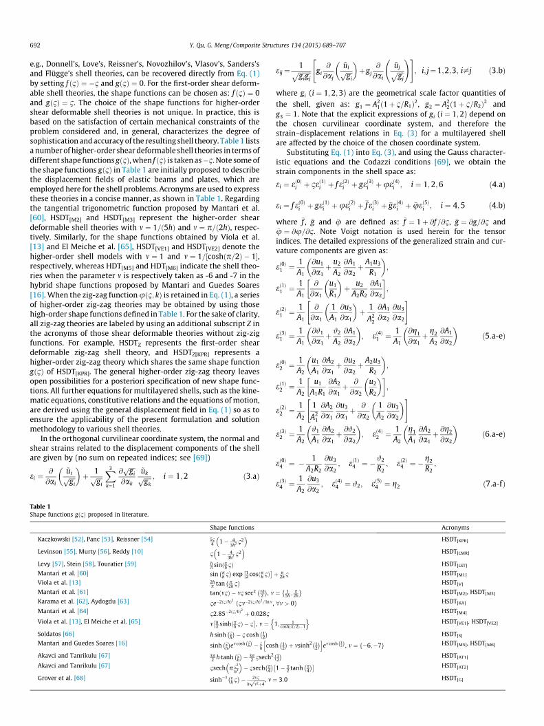
Thestartingpoint for thedirect formulationof theexterior acous-tic radiationproblemof anelastic body is thewell-knownKirchhoff–Helmholtz integral formula. Due to the axisymmetric properties of amultilayered composite shell of revolution, a global cylindrical coor-dinate system ðr; h; zÞ located on the axis of the shell is introducedherein to describe the acoustic field, as shown in Fig. 2.
In the cylindrical coordinate system, the Kirchhoff–Helmholtzintegral equation governing the exterior acoustic field of the shellcan be expressed as [31]:
CðrÞpðrÞ ¼ZS
pð�rÞ @Gðr;�rÞ@�n
� Gðr;�rÞ @pð�rÞ@�n
� �dS ð24Þ
where rðr; h; zÞ and �rð�r; �h;�zÞ are the position vectors of field pointsexterior to and on the fluid-shell interface S, respectively. p is thesound pressure. CðrÞ is a coefficient depending on the position offield point r, given as: CðrÞ ¼ 1 if r inside the acoustic medium,CðrÞ ¼ 1=2 if r on the shell surface, and CðrÞ ¼ 0 if r outside theacoustic medium. �n is the outward normal direction at a point onthe shell surface, and @=@�n represents the outward normal deriva-tive with respect to the shell. Gðr;�rÞ is the three-dimensional free-space Green’s function, written by
Gðr;�rÞ ¼ e�ikR0ðr;�rÞ
4pR0ðr;�rÞ ð25Þ
where k is the acoustic wave number, given as: k ¼ x=cf , and cf isthe speed of sound of the fluid. R0ðr;�rÞ is the distance between rand �r, expressed as:
R0ðr;�rÞ ¼ffiffiffiffiffiffiffiffiffiffiffiffiffiffiffiffiffiffiffiffiffiffiffiffiffiffiffiffiffiffiffiffiffiffiffiffiffiffiffiffiffiffiffiffiffiffiffiffiffiffiffiffiffiffiffiffiffiffiffiffiffiffiffiffiffiffiffiffiffiffiffir2 þ �r2 � 2r�r cosðh� �hÞ þ ðz� �zÞ2
qð26Þ
Considering the axisymmetric property of the fluid-shell inter-face involved, the field quantities of the fluid may be representedby Fourier series in the circumferential direction, and then theactual acoustic field quantities can be obtained by summing theFourier series over a sufficient number of harmonics. In doing so,we expand the pressure of the acoustic field with respect to theangle of revolution by using Fourier series. This gives
pðrÞ ¼X~Nn¼0
½psnðr;n; zÞ sinðnhÞ þ pc
nðr;n; zÞ cosðnhÞ� ð27:aÞ
pð�rÞ ¼X~Nn¼0
½�psnð�r;n;�zÞ sinðn�hÞ þ �pc
nð�r;n;�zÞ cosðn�hÞ� ð27:bÞ
where psn and pc
n are Fourier coefficients of the acoustic pressure atfield point rðr; h; zÞ; �ps
n and �pcn are the pressure coefficients related to
field point �rð�r; �h;�zÞ. n is the acoustic mode number in the circumfer-ential direction. Similarly, the Green’s function and its normalderivative can be expressed as:
Gðr;�rÞ ¼ 1pX~Nn¼0
Hn½sinðnhÞ sinðn�hÞ þ cosðnhÞ cosðn�hÞ� ð28:aÞ
@Gðr;�rÞ@�n
¼ 1pX~Nn¼0
�Hn½sinðnhÞ sinðn�hÞ þ cosðnhÞ cosðn�hÞ� ð28:bÞ
in which
Hn ¼Z 2p
0
e�ikR0
4pR0cosðnhÞdh; �Hn ¼
Z 2p
0
@
@�ne�ikR0
4pR0
� �cosðnhÞdh
ð29:a;bÞOn the shell-fluid interface, the normal displacement of the
shell is related to the normal gradient of the acoustic pressurethrough the momentum equation:
u3ð�rÞ ¼ 1qfx2 rpð�rÞ � �n ð30Þ
where qf is the density of the fluid, and u3ð�rÞ is the normal displace-
ment of point �rð�r; �h;�zÞ.Substituting Eqs. (27–30) and (22.c) into Eq. (24), and making
use of the orthogonality of sine and cosine integrals, one obtainsa modified form of the Kirchhoff–Helmholtz integral equation asfollows [39]:
CðrÞpsn ¼Z
lð�Hn�ps
n�qfx2Hn~us
3;nÞ�rdl;CðrÞpcn ¼Zlð�Hn�pc
n�qfx2Hn�uc
3;n�rdl
ð31:a;bÞwhere l is the generator line of the shell. Note the surface integral ofEq. (24) is reduced to a line integral along the generator of the shell,and all the pressure variables in Eq. (31) are independent of h.

Fig. 2. Coordinate system of the acoustic field.
696 Y. Qu, G. Meng / Composite Structures 134 (2015) 689–707
To establish the coupling matrices for the shell-fluid interaction,the acoustic boundary l is discretized into a fashion that the acous-tic boundary segments coincide with those of the shell segments.The sound pressure on each shell segment is expanded in the fol-lowing form
�p ¼XJ�1
j¼0
�PjðnÞ�pj ¼ �PðnÞ�p ð32Þ
where �PjðnÞ is the jth order Chebyshev orthogonal polynomials ofthe first kind. �pj is the generalized pressure. J is the number of totalterms of the polynomials. �PðnÞ is the polynomial function vector,defined as: �PðnÞ ¼ ½�P0ðnÞ; �P1ðnÞ; . . . ; �PJ�1ðnÞ�. �p is the column vectorcontaining generalized pressure variables, written by:�p ¼ ½�p0; �p1; . . . ; �pJ�1�T.
Substituting Eqs. (22c) and (32) into Eq. (31), the two modifiedKirchhoff–Helmholtz equations can be combined and written in acompact form as
C�PðrÞ�pnðrÞ ¼XNi¼1
Zlni
�HnðnÞ�PðnÞ�rðnÞJðnÞdn !
�pn
�XNi¼1
Zlni
qfx2HnðnÞU3ðnÞ�rðnÞJðnÞdn
!u3;n ð33Þ
where JðnÞ is the Jacobian of the coordinate transformation.To achieve a practical solution, the boundary integral equations
in Eq. (33) are explicitly enforced at a set of collocation points ri(see Fig. 2) on each shell segment, which are distributed over theroots of the Chebyshev polynomials of the first kind. In the localcoordinate, the roots nj are given as:
nj ¼ cosð2j� 1Þp
2J; j ¼ 1;2; . . . ; J ð34Þ
Note for the case of J = 1, the pressure variable on each shell seg-ment is assumed to be constant and the collocation point is placedat the center of each segment (i.e., n1 = 0), which leads to conven-tional constant boundary elements. For the case of J > 1, the pre-sent formulation results in discontinuous boundary elementssince the collocation points located at the zeros of Chebyshevorthogonal polynomials are physically placed inside of each shellsegment.
The collocation point ri varies over all shell segments, whichresults in a set of N � J algebraic equations for each circumferentialwave mode.
Considering circumferential wave modes n ¼ 0;1; . . . ; ~N, Eq.(33) can be arranged in a matrix form as
�H�p ¼ Gu3 ð35Þwhere �H and G are the assembled coefficient matrices resultingfrom all circumferential wave modes, given as: �H ¼ diag½�H1; �H2; . . . ; �Hn; . . . ; �H~N� and G ¼ diag ½G1;G2; . . . ;Gn; . . . ;G~N�, in which�Hn and Gn are assembled matrices of all shell segments for circum-ferential wave n, written by: �Hn ¼ diag ½�H1;n; �H2;n; . . . ; �Hi;n; . . . ; �HN;n�and Gn ¼ diag ½G1;n;G2;n; . . . ;Gi;n; . . . ;GN;n�. �p and u3 are the vectorscontaining the generalized pressure and the normal displacementcomponents of the shell, expressed as: �p ¼ diag½�p1; �p2; . . . ; �pn; . . . ; �p~N�T and u3 ¼ diag ½u3;1;u3;2; . . . ;u3;i; . . . ;u3;~N�T,where �pn and u3;n are assembled vectors of all shell segments forcircumferential wave n. The details expression of the coefficientmatrices �Hi;n and Gi;n for the ith segment corresponding to circum-ferential wave n are given as:
�Hi;n ¼Zlni
�HnðnÞ�PðnÞ�rðnÞJðnÞdn; Gi;n ¼Zlni
qfx2HnðnÞU3ðnÞ�rðnÞJðnÞdn
ð36ÞIn evaluating the coefficient matrices of �Hi;n and Gi;n, the inte-
grands may become singular. The singularities of these integrandscan be dealt with by using the adaptive Gaussian algorithm [25] orelliptic integrals [39].
The CHIEF method [46] is employed to remove the non-uniqueness of Eq.(35), which uses Eq. (33) with collocation pointsplaced outside of the fluid as a constraint. When the collocationpoints ri are put exterior of the fluid, the quantity CðrÞ is equal tozero, and Eq. (33) becomes
XNi¼1
Zlni
�HnðnÞ�PðnÞ�rðnÞJðnÞdn !
�pn
�XNi¼1
Zlni
qfx2HnðnÞWðnÞ�rðnÞJðnÞdn
!u3;n ¼ 0 ð37Þ
which leads to the following equation:
�Hc�p ¼ Gcu3 ð38ÞCombining Eqs. (35) and (38) results in an over-determined
system of equations, which may be solve by a least-squaresprocedure. The generalized pressure vector can be obtained asfollows
Y. Qu, G. Meng / Composite Structures 134 (2015) 689–707 697
�p ¼ ~Hþ1~Gu3 ð39Þ
where ~H and ~G are defined as: ~H ¼ ½�HT; �HTc �
Tand ~G ¼ ½GT;GT
c �T. ~Hþ1 is
the generalized inverse of ~H. For a multilayered composite shellloaded with a light fluid (e.g., air), the problems of shell vibrationand sound radiation can be solved independently. This means thatthe calculation of the radiated acoustic field from the shell is basedon the vibration response of the shell by assuming an in-vacuoshell. In doing so, the generalized acoustic load vector fp is removedfrom Eq. (23), and the structural displacement vector ~q can beobtained immediately. Once ~q is known, the generalized pressurevector �p on the acoustic boundary is computed accordingly by Eq.(39). Then, the pressure at any position in the fluid can be deter-mined from Eqs. (33), (32) and (27). However, this approach isnot valid for problems where the fluid impedance is comparableto that of the shell. In such cases, a structural–acoustic couplingscheme must be used to obtain the vibro-acoustic properties ofthe shell.
2.5. Coupled shell- fluid model
A standard approach to deal with the shell equations in couplingwith the acoustic equations is to eliminate the acoustic pressurefrom the two equations. In doing so, one obtains equations whichonly contain the displacement components. Substituting Eqs.(22c), (32) and (39) into Eq. (21) and introducing a transformationbetween the displacement vectors u3 and ~q, i.e., u3 ¼ T~q, the gener-alized fluid loading vector fp in Eq. (23) can be obtained as:
fp ¼ �TT�G~Hþ1~GT~q ¼ �½�x2MfðxÞ þ iCf ðxÞ�~q ð40Þwhere Mf and Cf are frequency-dependent real matrices. �x2Mf
and iCf represent the real and imaginary parts of TT�G~Hþ1~GT, respec-tively. �G is the fluid-shell coupling matrix assembled by the cou-pling matrices related to all circumferential wave modes, givenas: �G ¼ diag ½�G1; �G2; . . . ; �Gn; . . . ; �G~N�, where �Gn is the matrix for cir-
cumferential wave n, given by �Gn ¼ diag ½G1;n; G2;n;. . . ; Gi;n; . . . ; GN;n�.Gi;n is the fluid-shell coupling matrix of the ith shell segment corre-sponding to circumferential wave n, expressed as
Gi;n ¼Z Z
Si
Ui;T3 ðnÞ�PiðnÞdS ð41Þ
Substituting Eq. (40) into Eq.(23), the governing equation forthe vibro-acoustic problem of the shell becomes
�x2½Ms þMf ðxÞ�~qþ iCfðxÞ~qþ ðKs � Kk þ KjÞ~q ¼ fs ð42ÞThe above equation indicates that the effect of the fluid can be
viewed as added mass and damping. Once ~q is known from Eq.(42),the generalized pressure vector �p on the acoustic boundary is com-puted accordingly by Eq. (39). Subsequently, the pressure at anyposition in the fluid may be determined directly from Eqs. (33),(32) and (27).
3. Results and discussion
Some numerical examples have been solved in this section todemonstrate the accuracy and flexibility of the proposed theoryand method for predicting the vibration and acoustic responsesof multilayered shells of revolution. Before the application of thetheory and method to the acoustic problems of multilayered shells,numerical results pertaining to the free vibration of in-vacuo mul-tilayered shells are calculated based on the general higher-ordershear deformable zig-zag shell theory. Comparison studies havebeen conducted in order to evaluate the accuracy of various shelltheories. Once the validity and accuracy of higher-order zig-zag
shell theories are verified, numerical analyses concerning thesound radiation of multilayered spherical, cylindrical and conicalshells immersed in light and heavy fluid are implemented subse-quently. With regard to the acoustic responses of multilayeredshells, the results of present method are compared with exact ana-lytical solutions and numerical results of coupled FEM/BEM. Thecurvilinear coordinate systems employed in the present analysisfor multilayered spherical, cylindrical and conical shells are givenin Qu et al. [48]. For the acoustic analyses, unless stated otherwise,the light fluid (air) is characterized by density qf ¼ 1:225 kg/m3
and speed of sound cf ¼ 340 m/s, whereas qf ¼ 1026 kg/m3 andcf ¼ 1500 m/s are considered for the heavy fluid (water). In orderto consider the damping effects of the shells, structural dampingis introduce in the analysis by multiplying the global stuffinessmatrices of the shells by a complex coefficient ð1þ igÞ, where gis a loss factor taken as: g ¼ 0:005. All the reference results ofthe coupled FEM/BEM are converged numerical solutions obtainedby ANSYS and LMS Virtual. Lab. Acoustics, where the four-nodedSHELL 181 elements in ANSYS are used to model the multilayeredshells. The acoustic results of the shells are given in the forms ofsound pressure level (SPL) and sound power level (SWL), whichare decibel (dB) scale measures of the radiated sound pressure pand sound power W relative to reference values, expressed as:
SPL ¼ 20log10p
pRef
� �; SWL ¼ 10log10
WWRef
� �ð43:a;bÞ
where pRef is a reference sound pressure, defined as pRef ¼ 2� 10�5
Pa and pRef ¼ 1� 10�6 Pa for air and water, respectively. The refer-ence sound power for both air and water is taken asWRef ¼ 1� 10�12 W.
3.1. In-vacuo free vibration of multilayered shells
In this subsection, free vibration results are presented for in-vacuo composite laminated shells. For simplicity, we confine ourattention to the analyses of multilayered cylindrical shells. For afixed terms of polynomials assumed for the displacement field ofeach cylindrical shell segment, the vibration solutions of the pre-sent method can be achieved as accurate as desired by increasingthe number of shell segments decomposed in the axial directionof the shell. Table 3 lists the non-dimensional frequency parame-ters Xn;m ¼ xL2=h
ffiffiffiffiffiffiffiffiffiffiffiq=E2
pagainst the shell segment number N for
a cross-ply [0�/90�] laminated cylindrical shell with F-F boundaryconditions. The frequency parameters corresponding to circumfer-ential waves n ¼ 1;2;3 and axial modes m ¼ 1;2;3;4;9;10 areconsidered. The geometric and material data of the shell are givenas: L=R ¼ 5, h=R ¼ 0:05, R ¼ 1 ; E1=E2 ¼ 25, E2 ¼ 2 GPa,G12=E2 ¼0:5, G13=E2 ¼0:5, G23=E2 ¼0:2, l12 ¼0:25, q¼1500 kg/m3.The two layers of the cylindrical shell are assumed to be of equalthickness. The higher-order shear deformable zig-zag shell theory,HDTZ[LMR], is employed to describe the displacement field of theshell, and eight terms (i.e., ~P¼7) of the Chebyshev orthogonalpolynomials are chosen to expand the displacement componentsof each shell segment. It is observed from Table 3 that the calcu-lated frequencies of the present method exhibit rapid convergencetrend with an increase in the number of the shell segments. For allthe numerical cases considered herein, the discrepancy betweenthe solutions of N¼4 and N¼20 is very small, and the maximumdiscrepancy (¼ jXN¼4�XN¼20j=XN¼20�100%) is found to be lessthan 0.03% for the first 10 axial modes corresponding to each cir-cumferential wave.
To validate the accuracy of the present method, Table 4 lists thenon-dimensional frequency parameters Xn;m ¼ xL2=h
ffiffiffiffiffiffiffiffiffiffiffiq=E2
pof a
cross-ply [0�/90�/0�] laminated cylindrical shell with three types

Table 3Frequency parameters Xn;m ¼ xL2=h
ffiffiffiffiffiffiffiffiffiffiffiq=E2
pagainst the number of shell segments for a cross-ply [0�/90�] laminated cylindrical shell (boundary conditions: F-F).
Modes Number of shell segments
n m N = 2 N = 4 N = 6 N = 8 N = 10 N = 12 N = 15 N = 20
1 1 297.259 297.255 297.256 297.255 297.256 297.253 297.257 297.2592 335.511 335.511 335.510 335.510 335.511 335.510 335.511 335.5113 479.783 479.768 479.768 479.768 479.764 479.769 479.769 479.7714 599.715 599.643 599.667 599.672 599.672 599.673 599.675 599.6769 1212.783 1197.438 1197.482 1197.472 1197.528 1197.548 1197.571 1197.615
10 1300.796 1246.582 1246.510 1246.550 1246.523 1246.544 1246.555 1246.584
2 1 41.706 41.705 41.705 41.705 41.705 41.705 41.705 41.7052 42.553 42.550 42.548 42.548 42.548 42.548 42.547 42.5483 176.909 176.900 176.899 176.900 176.900 176.901 176.901 176.9034 270.740 270.707 270.706 270.707 270.707 270.708 270.710 270.7139 746.393 742.657 742.618 742.664 742.642 742.641 742.646 742.664
10 827.563 792.005 792.130 791.936 792.121 792.135 792.151 792.191
3 1 115.803 115.802 115.802 115.802 115.802 115.802 115.802 115.8022 116.868 116.865 116.863 116.863 116.863 116.863 116.863 116.8633 160.686 160.673 160.671 160.670 160.669 160.669 160.669 160.6694 222.684 222.641 222.636 222.634 222.634 222.634 222.634 222.6349 674.454 639.607 639.740 639.495 639.722 639.744 639.768 639.820
10 784.293 735.553 735.365 735.544 735.337 735.417 735.472 735.563
Table 4Frequency parameters Xn;m ¼ xL2=h
ffiffiffiffiffiffiffiffiffiffiffiq=E2
pfor a cross-ply [0�/90�/0�] laminated cylindrical shell with different boundary conditions (m ¼ 1).
n F–F S1–S1 C–C
HSDTZ[LMR] Ref. [71] FSDT Ref. [1] 3-D HSDTZ[LMR] Ref. [71] FSDT Ref. [1]3-D HSDTZ[LMR] Ref. [71] FSDT Ref. [1] 3-D
1 304.140 304.13 304.200 151.504 151.49 151.523 159.327 159.31 159.2142 27.205 26.575 26.553 92.757 92.574 92.562 107.859 107.71 107.5743 75.367 74.905 74.772 95.731 95.368 95.187 108.357 108.05 107.8544 143.092 142.93 142.488 150.574 150.42 149.918 157.369 157.23 156.7575 229.303 229.74 228.642 233.543 233.97 232.828 237.270 237.70 236.5847 453.433 456.60 452.462 456.282 459.42 455.279 457.843 460.98 456.852
10 903.579 917.18 901.390 906.047 919.60 903.854 906.764 920.32 904.573
698 Y. Qu, G. Meng / Composite Structures 134 (2015) 689–707
of boundary conditions, namely F–F, S1–S1 and C–C. The globalgeometric dimensions and material data of the shell follow thesame values of the previous case. Again, the higher-order zig-zagtheory HDTZ[LMR] is employed for the present analysis. The numer-ical results reported by Messina and Soldatos [71] based on a FSDTand the 3-D elasticity solutions of Qu et al. [1] are also given inTable 4 for comparison purpose. It should be noted that the FSDTused by Messina and Soldatos [71] fulfils the continuity of theinterlaminar stresses through the shell thickness. As observed fromTable 4, in the case of lower circumferential waves (n 6 5), thenon-dimensional frequency parameters obtained by FSDT andHDTZ[LMR] are both in close agreement with the 3-D elasticityresults. However, the present HDTZ[LMR] tends to give much accu-rate frequencies than those of FSDT in the case of higher circumfer-ential waves (e.g., n ¼ 10).
Comparisons of the numerical solutions obtained from differentshell theories for a cross-ply [0�/90�] laminated cylindrical shellwith S1–S1 boundary conditions are illustrated in Fig. 3. The geo-metric and material data of the shell are given in the previous case.The accurate results obtained by Matsunaga [72] are consideredhere as reference solutions. In Fig. 3, HSDT[R] and HSDTZ[R] repre-sent the higher-order shear deformable shell theories with
f ð1Þ ¼ �413=ð3h2Þ and gð1Þ ¼ 1� 413=ð3h2Þ. It is observed that allsolutions of the HSDT and HSDTZ are in close agreement with thereference results in the case of lower circumferential modes(n 6 6). The results of HSDT[VE1], HSDT[VE2], HSDT[G], HSDTZ[VE1],HSDTZ[VE2] and HSDTZ[G] tend to deviate significantly from the ref-erence solutions when higher circumferential modes (n > 7) areconcerned. In general, when the zig-zag function is introduced intothe displacement field of a HSDT, the accuracy of the frequencyparameters of the shell can be effectively improved. The max
discrepancy between the results of all shell theories without zig-zag function (i.e., FSDT and HSDTs) and the reference data is 4%for circumferential modes n 6 5, whereas such a discrepancy is lessthan 3.2% for all FSDTz and HSDTZ models. In the case of thecircumferential mode n ¼ 10, the maximum discrepancies of theHSDT[VE1], HSDT[VE2] and HSDT[G] with respect to the reference dataare 10.3%, 10.3% and 14.2%, respectively. For the HSDTZ[VE1], HSDTZ[VE2] and HSDTZ[G], the corresponding maximum discrepancies are7.1%, 7.1% and 9.4%, respectively. Another interesting observationis that the HSDT[VE1] and HSDT[VE2] produce identical results forall numerical cases. This is anticipated since they use the similarshape functions just with different multiplying coefficients.The same tendency is also observed for the HSDTZ[VE1] and HSDTZ[VE2].
3.2. Sound radiation of multilayered shells
3.2.1. Spherical shellThe sound radiation problems of a multilayered spherical shell
immersed in an infinite light or heavy fluid are examined in thissubsection. To achieve an exact analytical solution for comparisonpurpose, the spherical shell is assumed to be made of three layersof isotropic materials. The outer and inner layers are fabricated byzirconia (ceramic) with material properties given as: E ¼ 168 GPa,l ¼ 0:3, q ¼ 5700 kg/m3, and the core layer is made of aluminumwhose material properties are: E ¼ 70 GPa, l ¼ 0:3, q ¼ 2707kg/m3. The geometrical dimensions of the shell are:Ro ¼ 1:015 m, Ri ¼ 0:985 m, R ¼ ðRo þ RiÞ=2, and the three layersare of the same thickness. Damping effects of the shell areneglected. The inner surface of the shell is subjected to a uniformlydistributed force with an intensity of p0 ¼ 1 Pa, as shown in Fig. 4.

1 2 3 4 5 6 7 8 9 100
200
400
600
800
1000
1200
1400
1600
HSDT[KA] HSDT[M4] HSDT[VE1] HSDT[VE2] HSDT[S] HSDT[M5] HSDT[M6] HSDT[AT1] HSDT[AT2] HSDT[G]
Non
-dim
ensi
onal
freq
uenc
y n,m
Circumferential wave number
Ref.[72] FSDT HSDT[R] HSDT[KPR] HSDT[LMR] HSDT[LST] HSDT[M1] HSDT[V] HSDT[M2] HSDT[M3]
(a)
1300
1400
1500
1 2 3 4 5 6 7 8 9 100
200
400
600
800
1000
1200
1400
1600
HSDTZ[KA] HSDTZ[M4] HSDTZ[VE1] HSDTZ[VE2] HSDTZ[S] HSDTZ[M5] HSDTZ[M6] HSDTZ[AT1] HSDTZ[AT2] HSDTZ[G]
Non
-dim
ensi
onal
frequ
ency
n,m
Circumferential wave number n
Ref.[72] FSDTZ HSDTZ[R] HSDTZ[KPR] HSDTZ[LMR] HSDTZ[LST] HSDTZ[M1] HSDTZ[V] HSDTZ[M2] HSDTZ[M3]
(b)
1300
1400
1500
Fig. 3. Variation of non-dimensional frequencies against circumferential wave number n for a [0�/90�] laminated cylindrical shell: (a) shell theories without zig-zagfunctions; (b) shell theories with zig-zag functions.
Fig. 4. Multilayered spherical shell immersed in fluid: (a) shell model; (b) acoustic model.
Y. Qu, G. Meng / Composite Structures 134 (2015) 689–707 699
Fig. 5 illustrates the normal displacement of the shell referencesurface and the radiated sound pressure at an observation point Q0
(rQ0 ¼ 4 m;zQ0 ¼ 0) for the spherical shell immersed in air. In thiscase, a high acoustic impedance mismatch exists between the shelland air. Therefore, the structural and acoustic responses of theshell are solved one after the other. The spherical shell is dis-cretized into N ¼ 10 shell segments in the meridional direction,and the displacement components and sound pressure ofeach shell segment are expanded by eight (i.e., ~P ¼ 7) and three(i.e., J ¼ 3) terms of Chebyshev orthogonal polynomials, respec-tively. Note the external force applied on the inner surface isaxisymmetric with respect to the circumferential coordinate, andtherefore only the axisymmetric vibration modes of the shell canbe effectively excited. Consequently, the circumferential wavenumber of the displacement and pressure variables is truncatedas n ¼ 0 in the analysis. The first-order shear deformable zig-zagtheory, FSDTZ, is employed here to describe the displacement fieldof the shell. The exact solutions are obtained by solving the 3-Dtheory of elasticity combined with the 3-D wave equations; formore details see Appendix B. As can be observed from Fig. 5, thepresent solutions are in good correlation with the exact results.The comparison of the present results and the exact solutions for
the spherical shell immersed in water is presented in Fig. 6. In thiscase, the effect of the fluid pressure on the vibration of the shellcannot be neglected, and the strong coupling scheme for the struc-tural and acoustic equations is therefore employed. Again, thecomparison in Fig. 6 shows that the present method providesresults in excellent agreement with the exact solutions. This veri-fies the accuracy of present method for the structural–acousticcoupling analysis of multilayered shells.
3.2.2. Cylindrical shellThe radiation of sound frommultilayered cylindrical shells with
different boundary conditions is examined in this subsection. Theshells are terminated by infinitesimally thin, rigid circular bafflesat both ends, as shown in Fig. 7. It is assumed that the shells areexcited by normal distributed forces f w ð¼ �f weixtÞ with unitintensity.
To validate the accuracy of the present method, Fig. 8 shows thecomparison of the radiation directivity patterns for a cylindricalshell made of steel and immersed in air. The shell properties areas follows: L ¼ 2 m, R ¼ 1 m, H ¼ 0:01 m; E ¼ 210 GPa, l ¼ 0:3,q ¼ 7800 kg/m3. The location of the distributed surface force isdefine as: x0 ¼ 0 m, x1 ¼ 0:2 m, h0 ¼ �p=3 and h1 ¼ p=3. The

Fig. 5. A three-layered spherical shell in air: (a) normal displacement; (b) sound pressure level.
Fig. 6. A three-layered spherical shell in water: (a) normal displacement; (b) sound pressure level.
Fig. 7. Multilayered cylindrical shell immersed in fluid: (a) shell model; (b) acoustic model.
700 Y. Qu, G. Meng / Composite Structures 134 (2015) 689–707

0
1x10⁻⁵
2x10⁻⁵
3x10⁻⁵
4x10⁻⁵
5x10⁻⁵
0
20
40
60
80100
120
140
160
180
200
220
240
260 280
300
320
340
0
1x10⁻⁵
2x10⁻⁵
3x10⁻⁵
4x10⁻⁵
5x10⁻⁵
Soun
d pr
essu
re (P
a) Coupled FEM/BEM Present: J=1 Present: J=2 Present: J=3
(a)
0
1x10⁻⁵
2x10⁻⁵
3x10⁻⁵
0
20
40
60
80100
120
140
160
180
200
220
240
260 280
300
320
340
0
1x10⁻⁵
2x10⁻⁵
3x10⁻⁵
Soun
d pr
essu
re (P
a)
Coupled FEM/BEM Present: J=1 Present: J=2 Present: J=3
(b)
Fig. 8. Radiation directivity patterns of cylindrical shell: (a) RQ0 ¼ 15 m; (b) RQ0 ¼ 30 m.
Y. Qu, G. Meng / Composite Structures 134 (2015) 689–707 701
radiation directivity patterns are evaluated at RQ0 ¼ 15 m andRQ0 ¼ 30 m for the angles h ¼ 0 and 0 6 / 6 360o, where / isdefined in Fig. 7, and the excitation frequency of the external forceis 100 Hz. Since the shell is a homogenous structure, the FSDT isemployed here to describe the displacement field of the shell.The present solutions are obtained by dividing the generator linesof the shell and the rigid circular baffle into 9 and 3 segments,respectively. Eight terms (i.e., ~P ¼ 7) of the Chebyshev orthogonalpolynomials are used to expand the displacement components ofeach shell segment. To show the convergence rate of the presentmethod, different terms of Chebyshev orthogonal polynomialsare used for the pressure variable, namely J = 1, 2 and 3. The resultsobtained from the coupled FEM/BEM are included in the figures asreference solutions. It can be observed from Fig. 8 that the rate ofconvergence of present method for the sound radiation results isexcellent. The present solutions obtained by J ¼ 1 are in excellentagreement with the reference results.
The grouped modal contributions of the circumferential modesto the radiated sound power of a cross-ply [0�/90�] laminatedcylindrical shell immersed in air are illustrated in Fig. 9. The geo-metric and material data of the shell are given as: L=R ¼ 2,h=R ¼ 0:05, R ¼ 1 m; E1 ¼ 131 GPa, E2 ¼ 10:34 GPa, G12 ¼ G23
¼ 6:895 GPa, G13 ¼ 6:205 GPa, l12 ¼ 0:22, q ¼ 1627 kg/m3. Thetwo layers of are of equal thickness. The intensity and location of
0 50 100 150 200 250 300 350 400
-60
-40
-20
0
20
40
60
80
FEDC
B
SWL
(dB)
Frequency (Hz)
n=0:1 n=0:2 n=0:3 n=0:6 n=0:12
(a) A
Fig. 9. Radiated sound power level for a cross-ply [0�/90�] cylindric
the external force follow the same values and configuration ofthe previous case. Two types of boundary conditions are examined,namely F–C and S1–S1. From Fig. 9, the individual modal contribu-tions corresponding to different circumferential modes to the totalradiated sound power of the shell can be observed directly. Theresults indicate that for the cylindrical shell with the two typesof boundary conditions, some circumferential modes do not signif-icantly contribute to the radiated sound power for the frequencyrange considered. Moreover, the F–C cylindrical shell is more effi-cient to radiate sound than the S1–S1 shell. This is expected sincethe F–C cylindrical shell is much more flexible in bending than theshell with S1–S1 boundary conditions.
Sound pressure contours of the shell surface corresponding tothe peaks in Fig. 9 are given in Fig. 10. These sound pressure con-tours of the cylindrical shell serve to enhance our understandingon the physical insight of the radiation sound related to differentcircumferential modes. From Fig. 9(a), we notice that the peak Ais related to a n ¼ 2 vibration mode by comparing the groupedmodal contributions of n ¼ 0 : 1 and n ¼ 0 : 2. The results inFig. 10 vividly confirm that the peak A corresponds to aðn;mÞ ¼ ð2;1Þ vibration mode of the shell. The sound pressure con-tour for the shell under a 150 Hz excitation is also given in the fig-ure. Note this frequency does not coincide with any resonantvibration mode of the shell. The peaks C and F in the sound power
0 50 100 150 200 250 300 350 400
-60
-40
-20
0
20
40
60
FEDC
B
SWL
(dB)
Frequency (Hz)
n=0:1 n=0:2 n=0:3 n=0:6 n=0:12
(b)A
al shell with different boundary conditions: (a) F–C; (b) S1–S1.

F-C: A (105.1Hz) F-C: (150 Hz) F-C: C (173.5Hz) F-C: F (307.6Hz)
S1-S1: A (181.3Hz) S1-S1: B (210.9Hz) S1-S1: D (301.8Hz) S1-S1: F (343.5Hz)
00.5
11.5
-0.50
0.5
-1
-0.5
0
0.5
1
00.5
11.5
-0.50
0.5
-1
-0.5
0
0.5
1
00.5
11.5
-0.5
00.5
-1
-0.5
0
0.5
1
00.5
11.5
-0.50
0.5
-1
-0.5
0
0.5
1
00.5
11.5
-0.50
0.5
-1
-0.5
0
0.5
1
00.5
11.5
-0.50
0.5
-1
-0.5
0
0.5
1
00.5
11.5
-0.50
0.5
-1
0
0.5
1
00.5
11.5
-0.50
0.5
-1
0
0.5
1
Fig. 10. Sound pressure contours of shell reference surface for cross-ply [0�/90�] cylindrical shell with F–C and S1–S1 boundary conditions.
702 Y. Qu, G. Meng / Composite Structures 134 (2015) 689–707
level curves of the F–C cylindrical shell are identified as the,ðn;mÞ ¼ ð1;1Þ and ðn;mÞ ¼ ð2;2Þ vibration mode, respectively.Likewise, the peaks A, B, D and F in the sound power level curvesof the S1–S1 cylindrical shell correspond to the ðn;mÞ ¼ ð4;1Þ,ðn;mÞ ¼ ð2;1Þ, ðn;mÞ ¼ ð4;2Þ and ðn;mÞ ¼ ð1;2Þ vibration mode ofthe shell, respectively.
3.2.3. Conical shellAn attempt is made in this section to analyze the radiation of
sound from a two-layered conical shell due to a normal surfaceforce. The conical shell is closed by two infinitesimally thin, rigidcircular baffles at its two ends, as shown in Fig. 11. The outer layerand inner layer of the shell are fabricated from zirconia and alu-minum, respectively, and the material properties are given as:E ¼ 168 GPa, l ¼ 0:3, q ¼ 5700 kg/m3 for zirconia, and E ¼ 70 GPa,
Fig. 11. A two-layered conical shell immersed i
l ¼ 0:3, q ¼ 2707 kg/m3 for aluminum. The geometrical parame-ters of the shell are given as: R1 ¼ 0:5 m, R2 ¼ R1 þ 2 tana0,a0 ¼ p=8, h ¼ 0:02 m. The external force is applied on the shell inthe normal direction with its location defined as: s01 ¼ R1=sina0,s02 ¼ R1=sina0 þ 0:2= cosa0, h0 ¼ p=6. The intensity of the force istaken to be unit.
Fig. 12 shows the results of the radiated sound pressure leveland sound power level for the conical shell immersed in air andsubjected F–C boundary conditions. The sound pressure levelresults are evaluated at two observation points, namely Q0
(rQ0 ¼ 10 m, hQ0 ¼ 0, zQ0 ¼ 5 m) and Q1 (rQ1 ¼ 5 m, hQ1 ¼ 0,zQ1 ¼ 1 m). The present solutions are obtained by dividing the gen-erator lines of the shell and the rigid circular baffle into 10 and 3segments, respectively. The highest degree of the Chebyshevorthogonal polynomials taken for the shell displacement
n fluid: (a) shell model; (b) acoustic model.

0 40 80 120 160 200 240 280-120
-100
-80
-60
-40
-20
0
20
40
60
Point Q1
Point Q0
SPL
(dB)
Frequency (Hz)
Point Q0: Coupled FEM/BEM Point Q0: J=1 Point Q0: J=2 Point Q0: J=3 Point Q1: Coupled FEM/BEM Point Q1: J=1 Point Q1: J=2 Point Q1: J=3
0 40 80 120 160 200 240 280-90
-60
-30
0
30
60
90
C
DB
SWL
(dB)
Frequency (Hz)
Coupled FEM/BEM Present method: J=1 Present method: J=2 Present method: J=3
(b)(a)A
Fig. 12. Sound pressure level and sound power level of a two-layered conical shell: (a) SPL of two field points; (b) sound power level.
A (129.8Hz) B (170.6Hz) C (250.4Hz) D (266.3Hz)
1.52
2.53
-1
-0.5
0
0.5
1
-1
-0.5
0
0.5
1
1.52
2.53
-1
-0.5
0
0.5
1
-1
-0.5
0
0.5
1
1.52
2.53
-1
-0.5
0
0.5
1
-1
-0.5
0
0.5
1
1.52
2.53
-1
-0.5
0
0.5
1
-1
-0.5
0
0.5
1
Fig. 13. Sound pressure contour of shell reference surface for a two-layered F–C conical shell.
Y. Qu, G. Meng / Composite Structures 134 (2015) 689–707 703
components is ~P ¼ 7. To show the convergence rate of the presentmethod, the sound radiation results are determined by using dif-ferent terms of Chebyshev orthogonal polynomials for the pressurevariable. The circumferential wave number of the displacementand pressure variables is truncated as n ¼ 0 : 9. The FSDTZ is usedto describe the displacement field of the shell. The results obtainedby using the coupled FEM/BEM are included in the figures as refer-ence solutions.
It can be observed from Fig. 12 that the rate of convergence ofpresent method for the sound radiation results is excellent. Thepresent solutions obtained by J ¼ 1 are in excellent agreementwith the reference results. The sound pressure contours of the shellreference surface corresponding to the first four peaks in Fig. 12(b)are given in Fig. 13. The peaks A, B, C and D correspond to theðn;mÞ ¼ ð3;1Þ, ðn;mÞ ¼ ð2;1Þ, ðn;mÞ ¼ ð4;2Þ and ðn;mÞ ¼ ð3;2Þvibration modes of the shell, respectively.
4. Conclusions
This paper is dedicated to the study of the vibration and acous-tic radiation of multilayered shells of revolution immersed inunbounded light and heavy fluid. A general higher-order sheardeformable zig-zag shell theory is developed to describe the dis-placement field of multilayered shells with arbitrary curvatures.The general zig-zag theory leaves open possibilities to recover
various thin and shear deformable shell theories available in theliterature by introducing into the shell displacement approxima-tion with certain shape functions. Regarding the vibration andacoustic analyses of a multilayered shell of revolution, a modifiedvariational method combined with a multi-segment partitioningprocedure is employed to formulate the shell model based on thegeneral zig-zag shell theory. The acoustic field exterior to the shellis formulated in terms of a spectral Helmholtz integral formulationwith collocation points placed at the roots of orthogonal polynomi-als. The non-uniqueness solution of the acoustic integral equationsis alleviated by using CHIEF interior points. The displacement andsound pressure variables are expanded by Fourier series in the cir-cumferential direction and Chebyshev orthogonal polynomials inthe meridional direction. As a result, a 3-D vibro-acoustic problemof the shell is transformed into a set of uncoupled 1-D problems,corresponding to the harmonics of Fourier series. The use of Four-ier series allows the present method to account for the individualmodal contributions to the vibration response and total radiatedsound of multilayered shells directly. Numerical examples pertain-ing to the free vibration analyses of in-vacuo multilayered compos-ite cylindrical shells are examined based on the higher-order zig-zag shell theory. Comparison studies are conducted to evaluatethe accuracy of various shell theories. With regard to the acousticproblems, numerical analyses concerning the sound radiation ofmultilayered spherical, cylindrical and conical shells immersed inlight and heavy fluid are implemented. The accuracy and validity

704 Y. Qu, G. Meng / Composite Structures 134 (2015) 689–707
of the present method are established by comparing the presentresults with those solutions obtained by the exact analyticalmethod and the coupled FEM/BEM. Individual contributions ofthe circumferential wave modes to the radiated sound of multilay-ered shells are investigated. The theory and method presented hereprovide a general tool for greater physical insight into the exterioracoustic-structure interaction problems of multilayered shells ofrevolution.
Appendix A. Elastic coefficient matrices of multilayered shell
The detailed expressions of the elastic coefficient matrices Aand �A in Eq. (11) are given as
A ¼A11 A12 A16
A12 A22 A26
A16 A26 A66
264
375; �A ¼
�A44�A45
�A45�A55
" #ðA:1Þ
where Aij (i; j ¼ 1;2;6) and �Aij (i; j ¼ 4;5) are the elastic coefficientsof a multilayered shell. Other elastic coefficient matrices in Eq. (11),namely B; . . . ;N;O and �B; . . . ; �X; �Y, may be expanded in similarforms of A and �A. The elastic coefficients in these matrices aredefined as follows:
Aij;Bij;Cij;Dij;Eij;
Fij;Gij;Hij; Iij; Jij;Kij;
Lij;Mij;Nij;Oij
0B@
1CA¼
XNl
k¼1
Z 1kþ1
1k
1;1; f ;g;u;
12;1f ;1g;1u; f 2; fg;
fu;g2;gu;u2
0B@
1CA�Q ðkÞ
ij d1; i; j¼1;2;6
ðA:2Þ
�Aij; �Bij; �Cij; �Dij; �Eij; �Fij; �Gij;
�Hij;�Iij;�Jij; �Kij; �Lij; �Mij; �Nij;
�Oij; �Pij; �Rij; �Sij; �Tij; �Xij; �Yij
0B@
1CA
¼ ksXNl
k¼1
Z 1kþ1
1k
f 2; fg; fu; f�f ; f �g; f �u; g2;
gu; g�f ; g�g; g �u;u2;u�f ;u�g;
u �u;�f 2;�f �g;�f �u; �g2; �g �u; �u2
0B@
1CA�Q ðkÞ
ij d1; i; j ¼ 4;5
ðA:3Þ
Appendix B. Exact solution for vibro-acoustic problem of amultilayered spherical shell
For a multilayered spherical shell made of Nl isotropic andhomogeneous layers, the displacement field of each layer hasspherical symmetry when the inner surface of shell is subjectedto a uniform pressure. The displacement field u(k) of the kth layercan be expressed as:
uðkÞ ¼ r/ðkÞ ðB:1Þ
where /ðkÞ is a scalar potential function, and r is a gradientoperator.
Consider the Helmholtz resolution of the displacement vector interms of spherical coordinates (i.e., u, h, r; see Ref. [1] for moredetails) and the symmetry of the displacement filed of each layer,namely, uðkÞ ¼ ð@/ðkÞ=@rÞer ; we obtain [73]
d2/ðkÞ
dr2þ 2
rd/ðkÞ
drþ ðkðkÞs Þ2/ðkÞ ¼ 0 ðB:2Þ
where kðkÞs is a wave number, defined as: kðkÞs ¼ x=cðkÞs . cðkÞs is thepropagation velocity of the dilatational wave in the kth layer,
expressed as: cðkÞs ¼ffiffiffiffiffiffiffiffiffiffiffiffiffiffiffiffiffiffiffiffiffiffiffiffiffiffiffiffiffiffiffiffiffiffiffiffiffiðkðkÞ þ 2GðkÞÞ=qðkÞ
q, where kðkÞ and G(k) are the
Lamé constant and the shear modulus, respectively.The analytical solution of the Eq. (B.2) is given in the form:
/ðkÞðrÞ ¼ HðkÞ0
e�ikðkÞs r
rþ HðkÞ
1eik
ðkÞs r
rðB:3Þ
where HðkÞ0 and HðkÞ
1 are undetermined complex constants.Substituting Eq. (B.3) into Eq. (B.1), we obtain the normal dis-
placement component uðkÞ3 as
uðkÞ3 ¼ �HðkÞ
0e�ikðkÞs r
r2ikðkÞs r þ 1� �
þ HðkÞ1
eikðkÞs r
r2ikðkÞs r � 1� �
ðB:4Þ
The radial stress component of the kth layer can be found by adirect application of the constitutive equation in linear elasticity,given as
rðkÞ3 ¼ kðkÞ þ 2GðkÞ
� � duðkÞ3
drþ 2kðkÞ
uðkÞ3
rðB:5Þ
Substituting Eq. (B.4) into Eq. (B.5), the radial stress rðkÞ3 is
expressed as
rðkÞ3 ¼ HðkÞ
0
�~kðkÞ �ðkðkÞs rÞ2 þ i2kðkÞs r þ 2h i
� 2kðkÞ ikðkÞs r þ 1� �� e�ikðkÞs r
r3
þ HðkÞ1
�~kðkÞ �ðkðkÞs rÞ2 � i2kðkÞs r þ 2h i
þ 2kðkÞ ikðkÞs r � 1� �� eik
ðkÞs r
r3
ðB:6Þwhere ~kðkÞ is expressed as: ~kðkÞ ¼ kðkÞ þ 2GðkÞ.
For vibro-acoustic analyses of the multilayered spherical shellimmersed in an infinite acoustic fluid, the interface conditions ofadjacent layers as well as the boundary conditions on the innerand outer surfaces of the shell must be enforced to achieve a prac-tical solution. For the case of perfect layer interfaces, we have
uðk�1Þ3
���r¼rðkÞ
¼ uðkÞ3
���r¼rðkÞ
; rðk�1Þ3
���r¼rðkÞ
¼ rðkÞ3
���r¼rðkÞ
; k ¼ 2;3; . . . ;Nl
ðB:7ÞThe boundary condition on the inner surface of the shell is sim-
ply given as
rðkÞ3 ðrÞ
���r¼rðkÞ ;k¼1
¼ �p0 ðB:8Þ
where p0 is the amplitude of the prescribed pressure.The boundary condition on the outer surface of the shell is cou-
pled with the acoustic solution of the fluid field. The acoustic pres-sure radiated by a pulsating sphere having a uniformly radialsurface velocity can be expressed as [74]:
pðrÞ ¼ VriqfxR2
o
ikf Ro þ 1e�ikf ðr�RoÞ
rðB:9Þ
where Vr is the prescribed radial velocity on the outer surface of theshell. Ro is the outer radius of the sphere. qf is the density of thefluid. kf is the acoustic wave number, written by: kf =x/cf, wherecf is the speed of sound of the fluid.
For the vibro-acoustic problem of the multilayered sphericalshell, Vr is unknown a priori and can be represented by:
Vr ¼ ixuðkÞ3 ðrÞ
���r¼rðkþ1Þ ;k¼Nl
ðB:10Þ
Substituting Eq. (B.4) into Eq. (B.9) and considering the relation-ship defined in Eq. Eq. (10), we obtain
pðrÞ¼"HðkÞ
0 e�ikðNlÞs Ro ikðNlÞ
s Roþ1� �
�HðkÞ1 eik
ðNlÞs Ro ikðNlÞ
s Ro�1� �# qfx2
ikf Roþ1
� e�ikf ðr�RoÞ
rðB:11Þ
where the radius Ro of the outer surface of the spherical shell isgiven as: Ro ¼ rðNlþ1Þ.

Y. Qu, G. Meng / Composite Structures 134 (2015) 689–707 705
The boundary condition on the outer surface can be given as:
rðkÞ3 ðrÞ
���r¼rðkþ1Þ ;k¼Nl
¼ �pðrÞjr¼rðkþ1Þ ;k¼NlðB:12Þ
Regarding the multilayered spherical shell with Nl layers, the
total number of unknowns (i.e., HðkÞ0 and HðkÞ
1 ) is 2Nl. We have2ðNl � 1Þ equations in terms of interface conditions and twoboundary equations defined on the inner and outer surfaces ofthe shell. This leads to a system of 2Nl equations with 2Nl
unknowns. Therefore the system is well defined and is solvable.For a three-layered spherical shell, we obtain a linear system ofequations as follows:
H11 H12 0 0 0 0H21 H22 H23 H24 0 0H31 H32 H33 H34 0 00 0 H43 H44 H45 H46
0 0 H53 H54 H55 H56
0 0 0 0 H65 H66
2666666664
3777777775
Hð1Þ0
Hð1Þ1
Hð2Þ0
Hð2Þ1
Hð3Þ0
Hð3Þ1
266666666664
377777777775¼
�p0
00000
2666666664
3777777775
ðB:13Þ
Where
H11 ¼ ~kð1Þ � kð1Þs R1
� �2þ i2kð1Þs R1 þ 2
� �� 2kð1Þ ikð1Þs R1 þ 1
� �� �e�ikð1Þs R1
R31
ðB:14Þ
H12 ¼ ~kð1Þ � kð1Þs R1
� �2� i2kð1Þs R1 þ 2
� �þ 2kð1Þ ikð1Þs R1 � 1
� �� �eik
ð1Þs R1
R31
ðB:15Þ
H21 ¼ � e�ikð1Þs R2
R22
ikð1Þs R2 þ 1� �
ðB:16Þ
H22 ¼ eikð1Þs R2
R22
ikð1Þs R2 � 1� �
ðB:17Þ
H23 ¼ e�ikð2Þs R2
R22
ikð2Þs R2 þ 1� �
ðB:18Þ
H24 ¼ � eikð2Þs R2
R22
ikð2Þs R2 � 1� �
ðB:19Þ
H31 ¼ ~kð1Þ � kð1Þs R2
� �2þ i2kð1Þs R2þ2
� ��2kð1Þ ikð1Þs R2þ1
� �� �e�ikð1Þs R2
R32
ðB:20Þ
H32 ¼ ~kð1Þ � kð1Þs R2
� �2� i2kð1Þs R2þ2
� �þ2kð1Þ ikð1Þs R2�1
� �� �eik
ð1Þs R2
R32
ðB:21Þ
H33 ¼� ~kð2Þ � kð2Þs R2
� �2þ i2kð2Þs R2þ2
� ��2kð2Þ ikð2Þs R2þ1
� �� �e�ikð2Þs R2
R32
ðB:22Þ
H34 ¼� ~kð2Þ � kð2Þs R2
� �2� i2kð2Þs R2þ2
� �þ2kð2Þ ikð2Þs R2�1
� �� �eik
ð2Þs R2
R32
ðB:23Þ
H43 ¼ � e�ikð2Þs R3
R23
ikð2Þs R3 þ 1� �
ðB:24Þ
H44 ¼ eikð2Þs R3
R23
ikð2Þs R3 � 1� �
ðB:25Þ
H45 ¼ e�ikð3Þs R3
R23
ikð3Þs R3 þ 1� �
ðB:26Þ
H46 ¼ � eikð3Þs R3
R23
ikð3Þs R3 � 1� �
ðB:27Þ
H53 ¼ ~kð2Þ � kð2Þs R3
� �2þ i2kð2Þs R3þ2
� ��2kð2Þ ikð2Þs R3þ1
� �� �e�ikð2Þs R3
R33
ðB:28Þ
H54 ¼ ~kð2Þ � kð2Þs R3
� �2� i2kð2Þs R3þ2
� �þ2kð2Þ ikð2Þs R3�1
� �� �eik
ð2Þs R3
R33
ðB:29Þ
H55 ¼� ~kð3Þ � kð3Þs R3
� �2þ i2kð3Þs R3þ2
� ��2kð3Þ ikð3Þs R3þ1
� �� �e�ikð3Þs R3
R33
ðB:30Þ
H56 ¼� ~kð3Þ � kð3Þs R3
� �2� i2kð3Þs R3þ2
� �þ2kð3Þ ikð3Þs R3�1
� �� �eik
ð3Þs R3
R33
ðB:31Þ
H65¼ ~kð3Þ � kð3Þs R4
� �2þ i2kð3Þs R4þ2
� ��
� 2kð3Þ � qfx2R24
ikf R4þ1
!ikð3Þs R4þ1� �)e�ikð3Þs R4
R34
ðB:32Þ
H66 ¼ ~kð3Þ �ðkð3Þs R4Þ2 � i2kð3Þs R4 þ 2
h in
þ 2kð3Þ � qfx2R24
ikf R4 þ 1
!ikð3Þs R4 � 1� �) eik
ð3Þs R4
R34
ðB:33Þ
where Rj (j ¼ 1;2;3;4) are the radii of the inner surface, layer inter-faces and outer surface of the shell, defined as: Rj ¼ rðkÞ
��k¼j.
Eq. (B.13) is solved to obtain the constants HðkÞ0 and HðkÞ
1
(k ¼ 1;2;3). Once HðkÞ0 and HðkÞ
1 are known, the normal displacementresponse of the shell may be determined by Eq. (B.4) and corre-spondingly, the acoustic pressure at any field point can be foundby using Eq. (B.11).
References
[1] Qu Y, Meng G. Dynamic analysis of composite laminated and sandwich hollowbodies of revolution based on three-dimensional elasticity theory. ComposStruct 2014;112:378–96. http://dx.doi.org/10.1016/j.compstruct.2014.02.021.
[2] Carrera E. Theories and finite elements for multilayered, anisotropic,composite plates and shells. Arch Comput Methods Eng 2002;9(2):87–140.http://dx.doi.org/10.1007/BF02736649.
[3] Carrera E. Historical review of Zig-Zag theories for multilayered plates andshells. Appl Mech Rev 2003;56(3):287–308. http://dx.doi.org/10.1115/1.1557614.
[4] Toorani MH, Lakis AA. General equations of anisotropic plates and shellsincluding transverse shear deformations, rotary inertia and initial curvatureeffects. J Sound Vib 2000;237(4):561–615. http://dx.doi.org/10.1006/jsvi.2000.3073.
[5] Noor AK, Burton WS. Assessment of computational models for multilayeredcomposite shells. Appl Mech Rev 1990;43(3):67–97. http://dx.doi.org/10.1115/1.3119162.
[6] Qatu MS. Recent research advances in the dynamic behavior of shells: 1989–2000, part 1: laminated composite shells. Appl Mech Rev 2002;55(4):325–50.http://dx.doi.org/10.1115/1.1483079.

706 Y. Qu, G. Meng / Composite Structures 134 (2015) 689–707
[7] Qatu MS, Sullivan RW, Wang W. Recent research advances on the dynamicanalysis of composite shells: 2000–2009. Compos Struct 2010;93(1):14–31.http://dx.doi.org/10.1016/ j.compstruct.2010.05.014.
[8] Leissa AW. Vibration of shells (NASA SP-288). Washington, DC: USGovernment Printing Office; 1973.
[9] Koiter WT. A consistent first approximation in the general theory of thin elasticshells. In: Proceedings of the symposium on the theory of thin elasticshells. Amsterdam: North Holland Publishing Company; 1960.
[10] Reddy JN, Liu CF. A higher-order shear deformation theory of laminated elasticshells. Int J Eng Sci 1985;23(3):319–30. http://dx.doi.org/10.1016/0020-7225(85)90051-5.
[11] Qatu MS. Accurate equations for laminated composite deep thick shells. Int JSolids Struct 1999;36(19):2917–41. http://dx.doi.org/10.1016/S0020-7683(98) 00134-6.
[12] Reddy JN. Exact solutions of moderately thick laminated shells. J Eng Mech1984;110(5):794–809. http://dx.doi.org/10.1061/(ASCE)0733-9399(1984)110:5(794).
[13] Viola E, Tornabene F, Fantuzzi N. General higher-order shear deformationtheories for the free vibration analysis of completely doubly-curved laminatedshells and panels. Compos Struct 2013;95:639–66. http://dx.doi.org/10.1016/j.compstruct.2012.08.005.
[14] Ferreira AJM, Roque CMC, Jorge RMN. Modelling cross-ply laminated elasticshells by a higher-order theory and multiquadrics. Comput Struct 2006;84(19–20):1288–99.
[15] Khalili SMR, Tafazoli S, Malekzadeh K. Fard. Free vibrations of laminatedcomposite shells with uniformly distributed attached mass using higher ordershell theory including stiffness effect. J Sound Vib 2011;330(26):6355–71.http://dx.doi.org/10.1016/ j.jsv.2011.07.004.
[16] Mantari JL, Guedes Soares C. Analysis of isotropic and multilayered plates andshells by using a generalized higher-order shear deformation theory. ComposStruct 2012;94(8):2640–56. http://dx.doi.org/10.1016/j.compstruct.2012.03.018.
[17] Carrera E. On the use of the Murakami’s zig-zag function in the modeling oflayered plates and shells. Comput Struct 2004;82(7–8):541–54. http://dx.doi.org/10.1016/j.compstruc. 2004.02.006.
[18] Icardi U, Ruotolo R. Laminated shell model with second-order expansion of thereciprocals of Lamé coefficients Ha, Hb and interlayer continuities fulfilment.Compos Struct 2002;56(3):293–313. http://dx.doi.org/10.1016/S0263-8223(02)00014-4.
[19] Oh J, Cho M. Higher order zig-zag theory for smart composite shells undermechanical-thermo-electric loading. Int J Solids Struct 2007;44(1):100–27.http://dx.doi.org/10.1016/j.ijsolstr.2006.04.017.
[20] Carrera E. Developments, ideas, and evaluations based upon Reissner’s mixedvariational theorem in the modeling of multilayered plates and shells. ApplMech Rev 2001;54(4):301–29. http://dx.doi.org/10.1115/1.1385512.
[21] Epstein M, Glockner PG. Nonlinear analysis of multilayered shells. Int J SolidsStruct 1977;13(11):1081–9. http://dx.doi.org/10.1016/0020-7683(77)90078-6.
[22] Reddy JN. On the generalization of displacement-based laminate theories. ApplMech Rev 1989;42(11s):s213–22. http://dx.doi.org/10.1115/1.3152393.
[23] Carrera E. Multilayered shell theories accounting for layerwise mixeddescription, part 1: governing equations. AIAA J 1999;37(9):1107–16. http://dx.doi.org/10.2514/2.821.
[24] Carrera E. Multilayered shell theories accounting for layerwise mixeddescription, part 2: numerical evaluations. AIAA J 1999;37(9):1117–24.http://dx.doi.org/10.2514/2.822.
[25] Skelton EA, James JH. Theoretical acoustics of underwaterstructures. London: Imperial College Press; 1997.
[26] Harari A, Sandman BE. Vibratory response of laminated cylindrical shellsembedded in an acoustic fluid. J Acoust Soc Am 1976;117(60):117–28. http://dx.doi.org/10.1121/1.381079.
[27] Yin XW, Liu LJ, Hua HX, Shen RY. Acoustic radiation from an infinite laminatedcomposite cylindrical shell with doubly periodic rings. J Vib Acoust 2009;131(1):1–9. http://dx.doi.org/10.1115/1.2980376. 011005.
[28] Daneshjou K, Nouri A, Talebitooti R. Sound transmission through laminatedcomposite cylindrical shells using analytical model. Arch Appl Mech 2007;77(6):363–79. http://dx.doi.org/10.1007/s00419-006-0096-7.
[29] Cao X, Hua H, Ma C. Acoustic radiation from shear deformable stiffenedlaminated cylindrical shells. J Sound Vib 2012;331(3):651–70. 10.1016 /j.jsv.2011.10.006.
[30] Marburg S, Nolte B. Computational acoustics of noise propagation in fluids –finite and boundary element methods. Leipzig: Springer-Verlag BerlinHeidelberg; 2008.
[31] Ciskowski RD, Brebbia CA. Boundary element methods inacoustics. Southampton: Computational Mechanics Publications; 1991.
[32] Everstine GC, Henderson FM. Coupled finite element/boundary elementapproach for fluid–structure interaction. J Acoust Soc Am 1990;87(5):1938–47. http://dx.doi.org/10.1121/1.399320.
[33] Jeans RA, Mathews IC. Solution of fluid-structure interaction problems using acoupled finite element and variational boundary element technique. J AcoustSoc Am 1990;88(5):2459–66. http://dx.doi.org/10.1121/1.400086.
[34] Chen S, Liu Y. A unified boundary element method for the analysis of soundand shell-like structure interactions. I. Formulation and verification. J AcoustSoc Am 1999;106(3):1247–54. http://dx.doi.org/10.1121/1.427158.
[35] Caresta M, Kessissoglou NJ. Structural and acoustic responses of a fluid-loadedcylindrical hull with structural discontinuities. Appl Acoust 2009;70(7):954–63. http://dx.doi.org/10.1016/j.apacoust.2008.11.004.
[36] Peters H, Kessissoglou N, Marburg S. Modal decomposition of exterioracoustic-structure interaction problems with model order reduction. JAcoust Soc Am 2013;133(5):2706–17. http://dx.doi.org/10.1121/1.4796114.
[37] Peters H, Kinns R, Kessissoglou NJ. Effects of internal mass distribution and itsisolation on the acoustic characteristics of a submerged hull. J Sound Vib2014;333(6):1684–97. http://dx.doi.org/10.1016/j.jsv.2013.10.017.
[38] Denli H, Sun JQ. Structural-acoustic optimization of sandwich cylindrical shellsfor minimum interior sound transmission. J Sound Vib 2008;316(1–5):32–49.http://dx.doi.org/10.1016/j.jsv.2008.02.027.
[39] Soenarko B. A boundary element formulation for radiation of acoustic wavesfrom axisymmetric bodies with arbitrary boundary conditions. J Acoust SocAm 1993;93(2):631–9. http://dx.doi.org/10.1121/1.405482.
[40] Kuijpers AHWM, Verbeek G, Verheij JW. An improved acoustic Fourierboundary element method formulation using fast Fourier transformintegration. J Acoust Soc Am 1997;102(3):1394–401. http://dx.doi.org/10.1121/1.420099.
[41] Tsinopoulos SV, Agnantiaris JP, Polyzos D. An advanced boundary element/fastFourier transform axisymmetric formulation for acoustic radiation and wavescattering problems. J Acoust Soc Am 1999;105(3):1517–26. http://dx.doi.org/10.1121/1.426691.
[42] Wang W, Atalla N, Nicolas J. A boundary integral approach for acousticradiation of axisymmetric bodies with arbitrary boundary conditions valid forall wave numbers. J Acoust Soc Am 1997;101(3):1468–78. http://dx.doi.org/10.1121/1.418174.
[43] Wright L, Robinson SP, Humphrey VF. Prediction of acoustic radiation fromaxisymmetric surfaces with arbitrary boundary conditions using the boundaryelement method on a distributed computing system. J Acoust Soc Am1999;125(3):1374–83. http://dx.doi.org/10.1121/1.3056467.
[44] Caresta M, Kessissoglou NJ. Acoustic signature of a submarine hull underharmonic excitation. Appl Acoust 2010;71(1):17–31. http://dx.doi.org/10.1016/j.apacoust.2009.07.008.
[45] Qu Y, Hua H, Meng G. Vibro-acoustic analysis of coupled spherical-cylindrical-spherical shells stiffened by ring and stringer reinforcements. J Sound Vib2015;355:345–59. http://dx.doi.org/10.1016/j.jsv.2015.06.034.
[46] Schenck HA. Improved integral formulation for acoustic radiation problems. JAcoust Soc Am 1968;44(1):41–58. http://dx.doi.org/10.1121/1.1911085.
[47] Burton AJ, Miller GF. The application of integral equation methods to thenumerical solution of some exterior boundary-value problems. Proc R Soc A:Math Phys Eng Sci 1971;323(1553):201–10. http://dx.doi.org/10.1098/rspa.1971.0097.
[48] Qu Y, Long X, Wu S, Meng G. A unified formulation for vibration analysis ofcomposite laminated shells of revolution including shear deformation androtary inertia. Compos Struct 2013;98:169–91. http://dx.doi.org/10.1016/j.compstruct.2012.11.001.
[49] Qu Y, Long X, Yuan G, Meng G. A unified formulation for vibration analysis offunctionally graded shells of revolution with arbitrary boundary conditions.Compos B Eng 2013;50:381–402. http://dx.doi.org/10.1016/j.compositesb.2013.02.028.
[50] Qu Y, Meng G. Three-dimensional elasticity solution for vibration analysis offunctionally graded hollow and solid bodies of revolution. Part I: theory. Eur JMech A Solids 2014;44:222–33. http://dx.doi.org/10.1016/j.euromechsol.2013.11.004.
[51] Qu Y, Meng G. Three-dimensional elasticity solution for vibration analysis offunctionally graded hollow and solid bodies of revolution. Part II: application.Eur J Mech A Solids 2014;44:234–48. http://dx.doi.org/10.1016/j.euromechsol.2013.11.004.
[52] Kaczkowski Z. Plates. Statical Analysis. Warsaw: Arkady; 1968.[53] Panc V. Theories of elastic plates. Prague: Academia; 1975.[54] Reissner E. On transverse bending of plates, including the effect of transverse
shear deformation. Int J Solids Struct 1975;11(5):569–73. http://dx.doi.org/10.1016/0020-7683(75)90030-X.
[55] Levinson M. A new rectangular beam theory. J Sound Vib 1981;74(1):81–7.http://dx.doi.org/10.1016/0022-460X(81)90493-4.
[56] Murty AVK. Toward a consistent beam theory. AIAA J. 1984;22(6):811–6.http://dx.doi.org/10.2514/3.8685.
[57] Levy M. Memoire sur la theorie des plaques elastique planes. Journal demathématiques pures et appliquées 1877;30:219–306.
[58] Stein M. Nonlinear theory for plates and shells including the effect oftransverse shearing. AIAA J 1986;24(9):1537–44. http://dx.doi.org/10.2514/3.9477.
[59] Touratier M. An efficient standard plate theory. Int J Eng Sci 1991;29(8):901–16. http://dx.doi.org/10.1016/0020-7225(91)90165-Y.
[60] Mantari JL, Oktem AS, Guedes Soares C. A new higher order shear deformationtheory for sandwich and composite laminated plates. Compos B Eng 2012;43(3):1489–99. http://dx.doi.org/10.1016/j.compositesb.2011.07.017.
[61] Mantari JL, Oktem AS, Guedes Soares C. A new trigonometric sheardeformation theory for isotropic, laminated composite and sandwich plates.Int J Solids Struct 2012;49(1):43–53. http://dx.doi.org/10.1016/j.ijsolstr.2011.09.008.
[62] Karama M, Afaq KS, Mistou S. Mechanical behaviour of laminated compositebeam by the new multi-layered laminated composite structures model with

Y. Qu, G. Meng / Composite Structures 134 (2015) 689–707 707
transverse shear stress continuity. Int J Solids Struct 2003;40(6):1525–46.http://dx.doi.org/10.1016/S0020-7683(02)00647-9.
[63] Aydogdu M. A new shear deformation theory for laminated composite plates.Compos Struct 2009;89(1):94–101. http://dx.doi.org/10.1016/j.compstruct.2008.07.008.
[64] Mantari JL, Oktem AS, Guedes Soares C. Static and dynamic analysis oflaminated composite and sandwich plates and shells by using a new higher-order shear deformation theory. Compos Struct 2011;94(1):37–49. http://dx.doi.org/10.1016/j.compstruct.2011.07.020.
[65] El Meiche N, Tounsi A, Ziane N, Mechab I, Adda.bedia EA. A new hyperbolicshear deformation theory for buckling and vibration of functionally gradedsandwich plate. Int J Mech Sci 2011;53(4):237–347. http://dx.doi.org/10.1016/j.ijmecsci.2011.01.004.
[66] Soldatos KP. A transverse shear deformation theory for homogeneousmonoclinic plates. Acta Mech 1992;94(3–4):195–220. http://dx.doi.org/10.1007/BF01176650.
[67] Akavci SS, Tanrikulu AH. Buckling and free vibration analyses of laminatedcomposite plates by using two new hyperbolic shear-deformation theories.Mech Compos Mater 2008;44(2):145–54. http://dx.doi.org/10.1007/s11029-008-9004-2.
[68] Grover N, Maiti DK, Singh BN. A new inverse hyperbolic shear deformationtheory for static and buckling analysis of laminated composite and sandwichplates. Compos Struct 2013;95:667–75. http://dx.doi.org/10.1016/j.compstruct.2012.08.012.
[69] Reddy JN. Mechanics of laminated composite plates and shells: theory andanalysis. 2nd ed. Florida: CRC Press; 2003.
[70] Vinson JR, Sierakowski RL. The behavior of structures composed of compositematerials. 2nd ed. Dordrecht: Kluwer Academic Publishers; 2002.
[71] Messina A, Soldatos KP. Ritz-type dynamic analysis of cross-ply laminatedcircular cylinders subjected to different boundary conditions. J Sound Vib1999;27(4):749–68. http://dx.doi.org/10.1006/jsvi.1999.2347.
[72] Matsunaga H. Vibration and buckling of cross-ply laminated compositecircular cylindrical shells according to a global higher-order theory. Int JMech Sci 2007;49(9):1060–75. http://dx.doi.org/10.1016/j.ijmecsci.2006.11.008.
[73] Graff KF. Wave motion in elastic solids. New York: Dover Publications, Inc.;1991.
[74] Cremer L, Heckl M, Petersson BAT. Structure-borne sound. 3rded. Berlin: Springer; 2010.