Embed Size (px)
Citation preview
Vibration Institute © SKF Group Slide 0
Vibration Institute Piedmont Chapter Symposium 2011
Presented by Tom McDermott
SKF Sr. Application Engineer
Friday May 13, 2011
® SKF is a registered trademark of SKF USA Inc.
© 2010 SKF USA Inc.
The contents of this publication are the copyright of the publisher and may not be reproduced (even extracts) unless prior written permission is granted. Every care has been taken to ensure the accuracy of the information contained in this publication but no liability can be accepted for any loss or damage whether direct, indirect or consequential arising out of useof the information contained herein.
Vibration Institute © SKF Group Slide 2
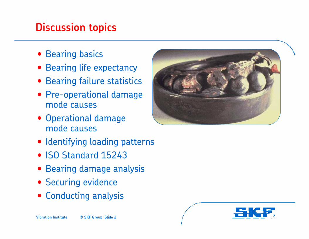
Discussion topics
• Bearing basics
• Bearing life expectancy
• Bearing failure statistics
• Pre-operational damage mode causes
• Operational damage mode causes
• Identifying loading patterns
• ISO Standard 15243
• Bearing damage analysis
• Securing evidence
• Conducting analysis
Vibration Institute © SKF Group Slide 3
SKF bearing basics
• Purpose and functions of a bearing
• Bearing components and materials
• Types of bearing loads
• Rolling elements – ball vs. roller
• Contact angle
• Precision class
• Radial and axial clearance
Vibration Institute © SKF Group Slide 4
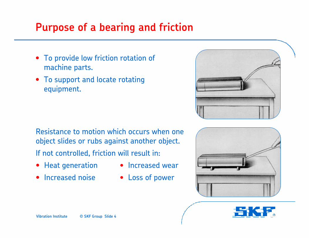
Purpose of a bearing and friction
• To provide low friction rotation of machine parts.
• To support and locate rotating equipment.
Resistance to motion which occurs when one object slides or rubs against another object.
If not controlled, friction will result in:
• Heat generation • Increased wear
• Increased noise • Loss of power
Vibration Institute © SKF Group Slide 5
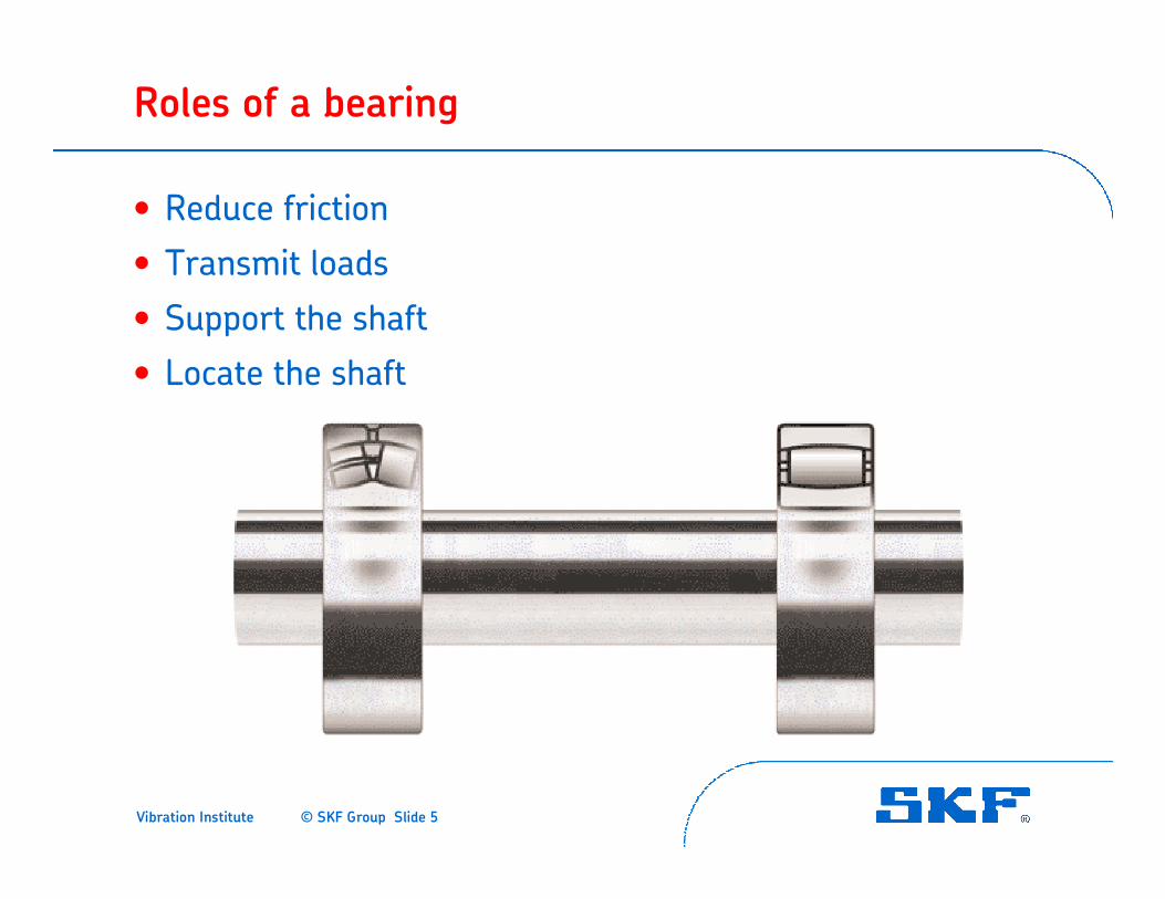
Roles of a bearing
• Reduce friction
• Transmit loads
• Support the shaft
• Locate the shaft
Vibration Institute © SKF Group Slide 6
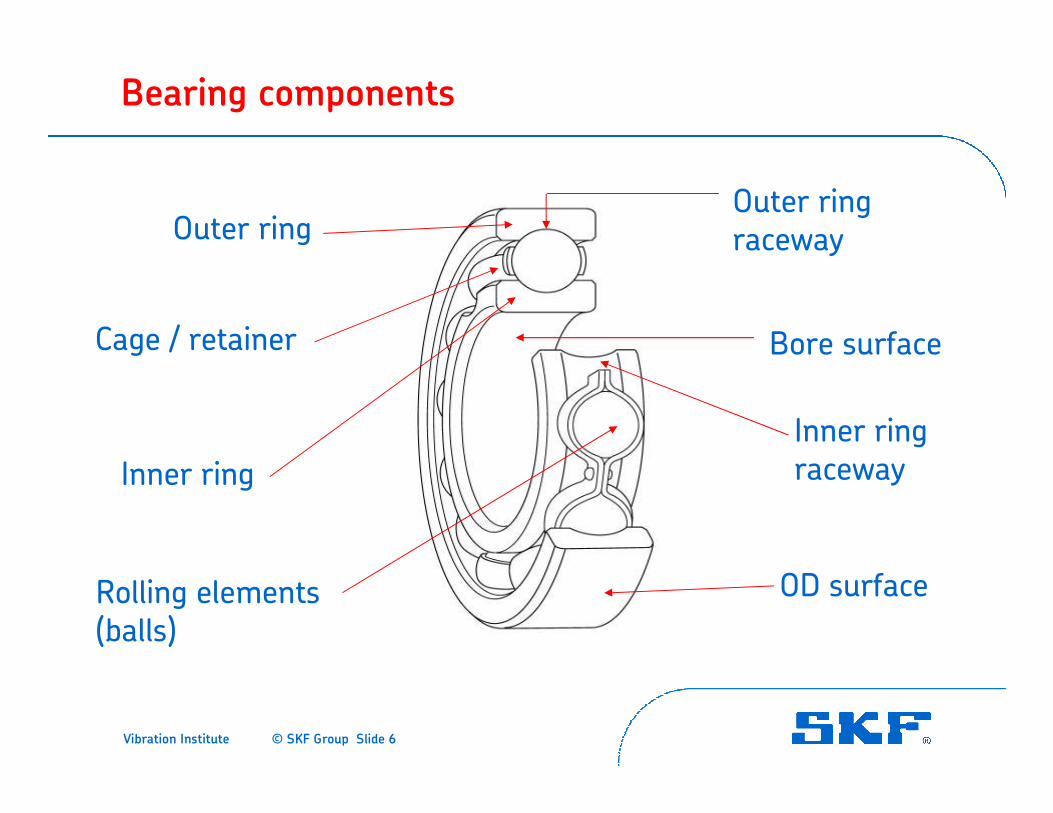
Bearing components
Outer ring
Cage / retainer
Inner ring
Rolling elements (balls)
Outer ring raceway
Bore surface
Inner ring raceway
OD surface
Vibration Institute © SKF Group Slide 7
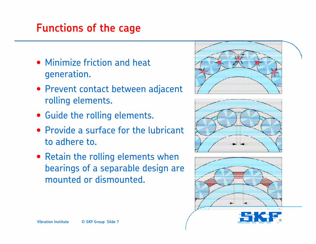
Functions of the cage
• Minimize friction and heat generation.
• Prevent contact between adjacent rolling elements.
• Guide the rolling elements.
• Provide a surface for the lubricant to adhere to.
• Retain the rolling elements when bearings of a separable design are mounted or dismounted.
Vibration Institute © SKF Group Slide 8
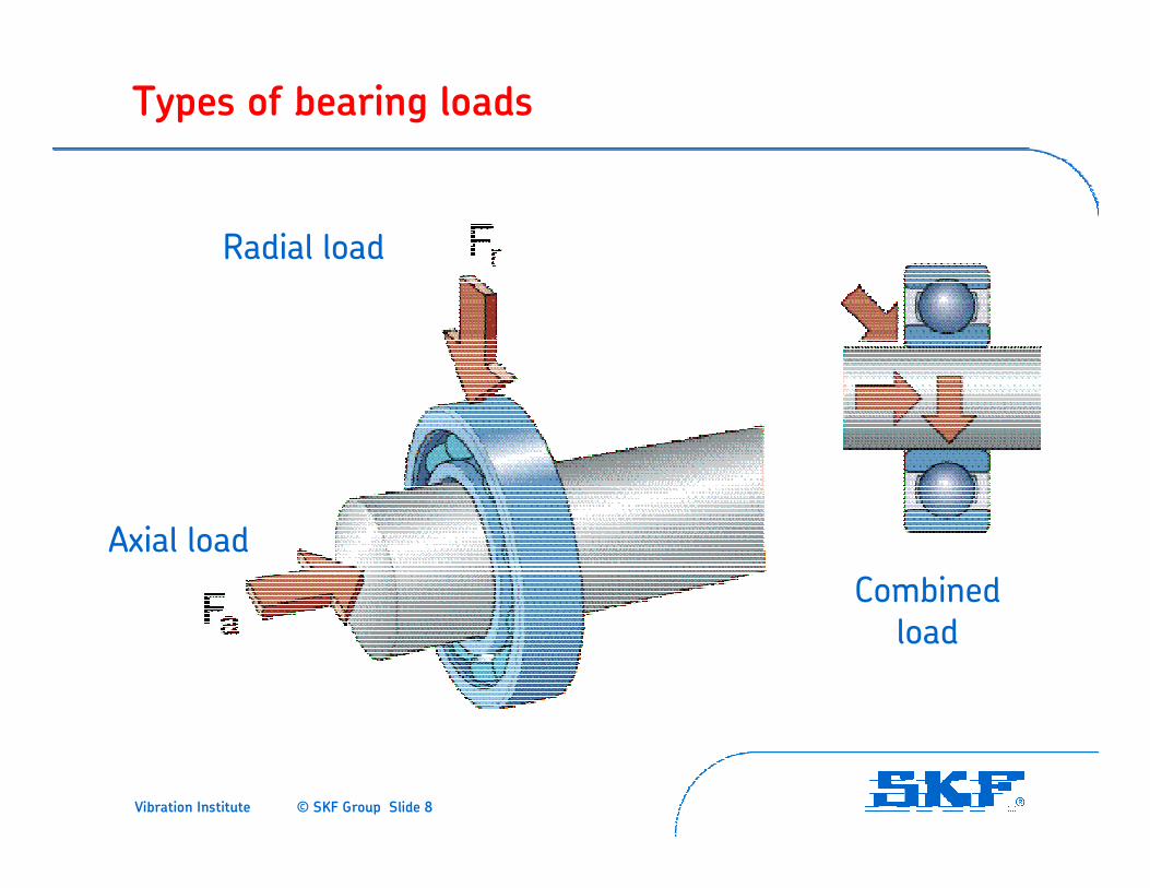
Types of bearing loads
Radial load
Axial load
Combined load
Vibration Institute © SKF Group Slide 9
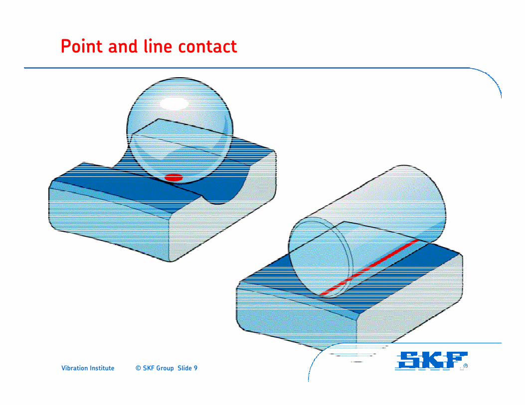
Point and line contact
Vibration Institute © SKF Group Slide 10
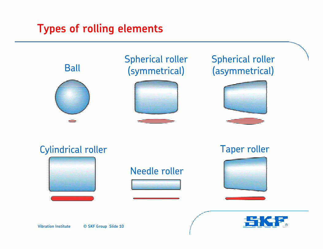
Types of rolling elements
Spherical roller(asymmetrical)
Taper roller
Spherical roller(symmetrical)
Needle roller
Cylindrical roller
Ball
Vibration Institute © SKF Group Slide 11
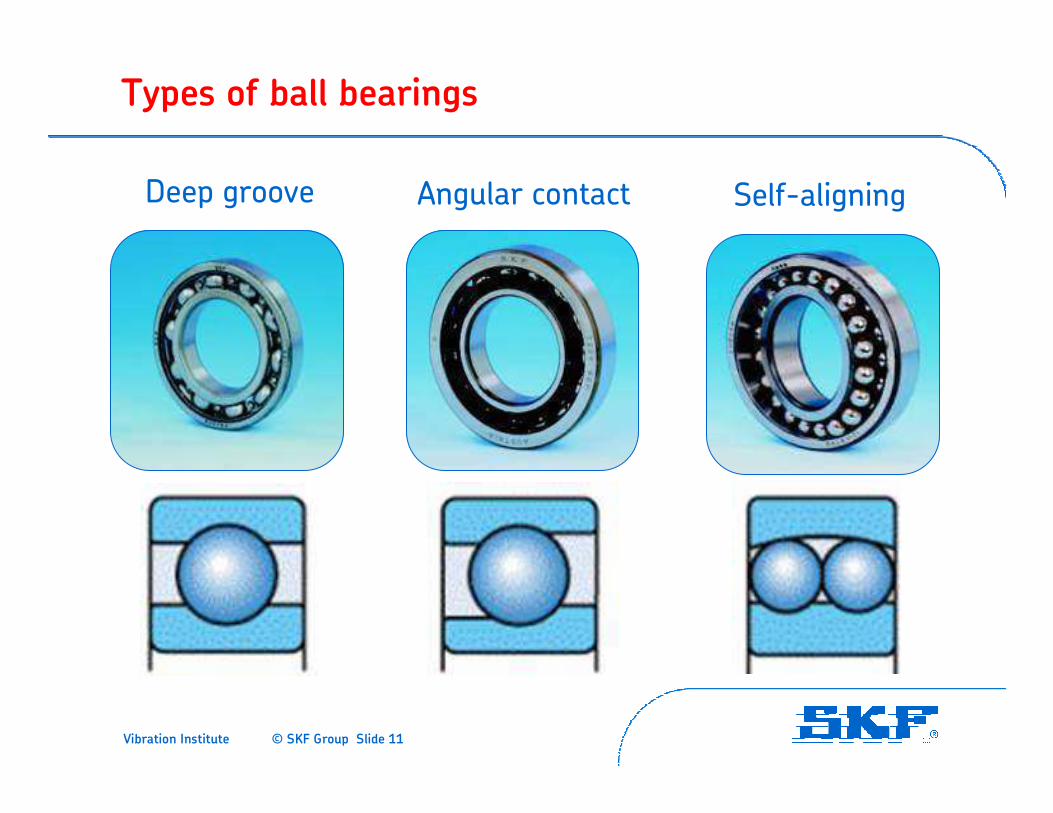
Types of ball bearings
Self-aligningAngular contactDeep groove
Vibration Institute © SKF Group Slide 12
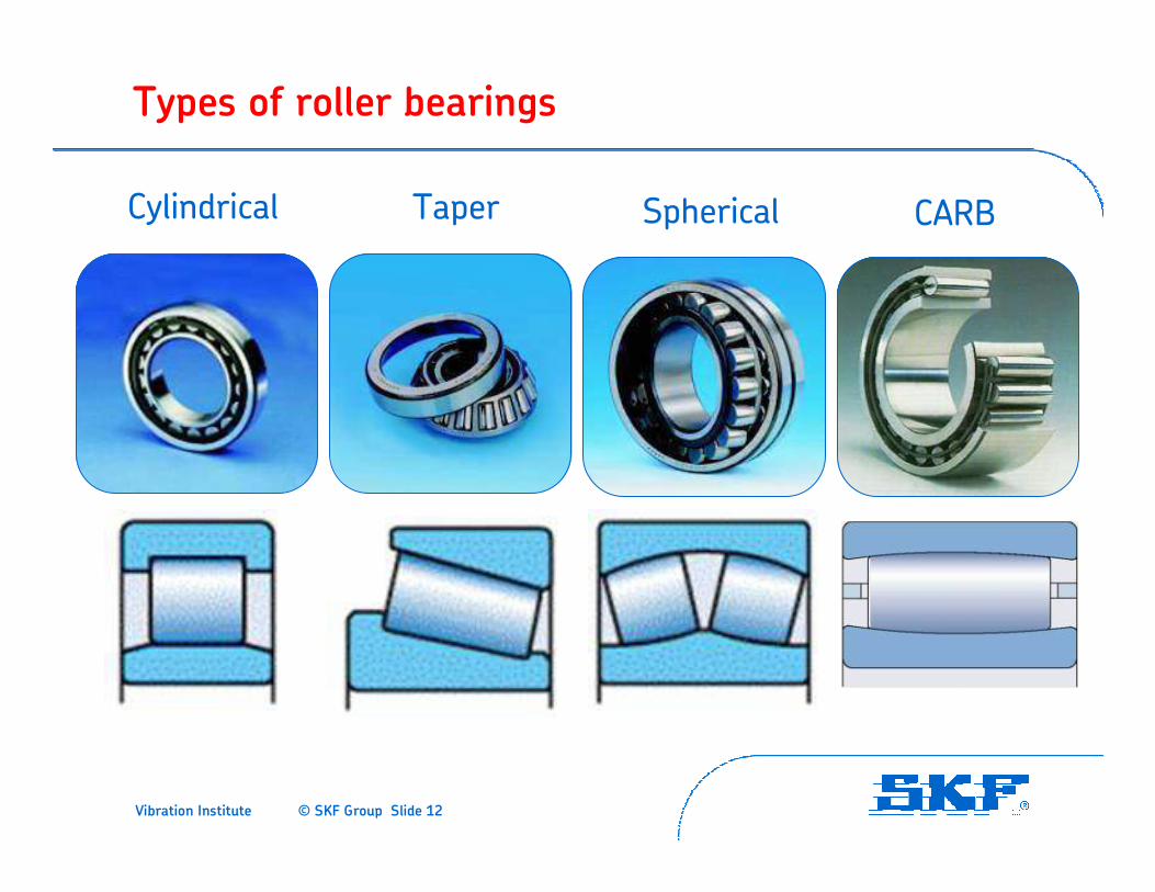
Types of roller bearings
Cylindrical SphericalTaper CARB

Vibration Institute © SKF Group Slide 13
Load carrying capacity relative to bearing type
Load carrying capacityis expressed as the “basic dynamic load rating”or “C” in catalogs
Vibration Institute © SKF Group Slide 14
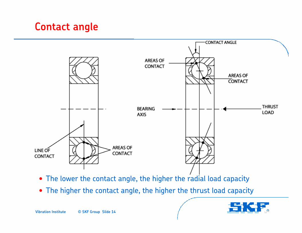
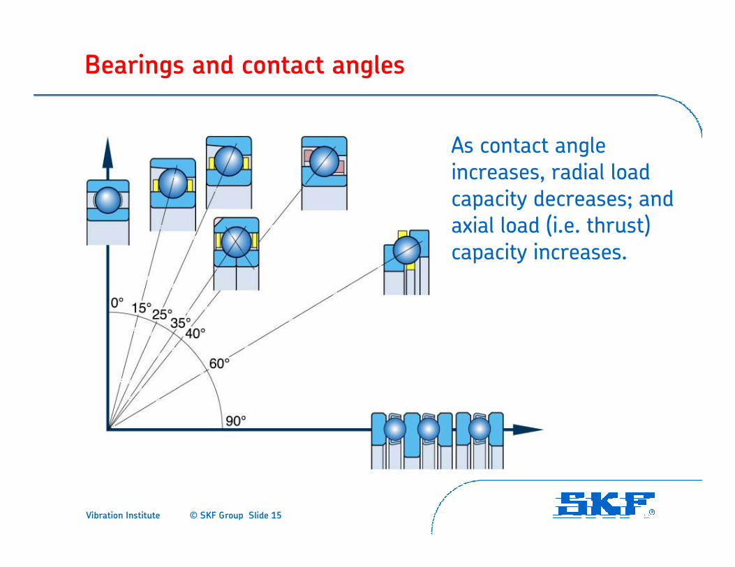
Contact angle
• The lower the contact angle, the higher the radial load capacity
• The higher the contact angle, the higher the thrust load capacity
Vibration Institute © SKF Group Slide 15
Bearings and contact angles
As contact angle increases, radial load capacity decreases; and axial load (i.e. thrust) capacity increases.
Vibration Institute © SKF Group Slide 16
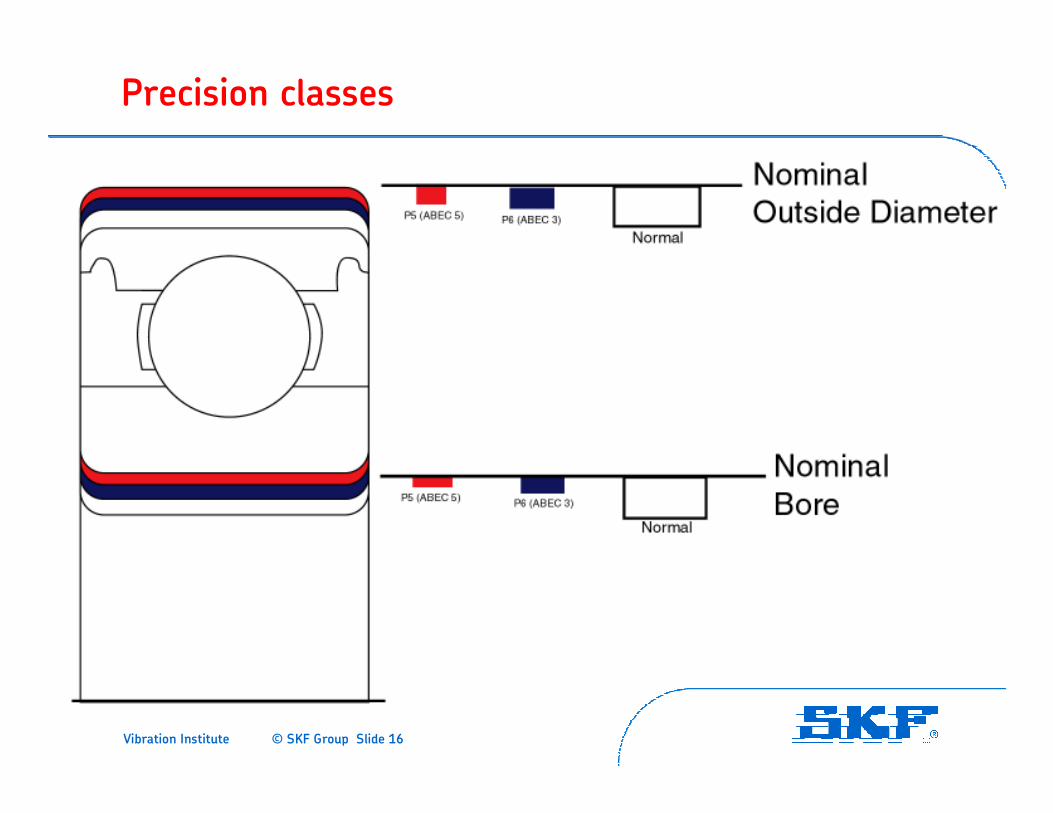
Precision classes
Vibration Institute © SKF Group Slide 17
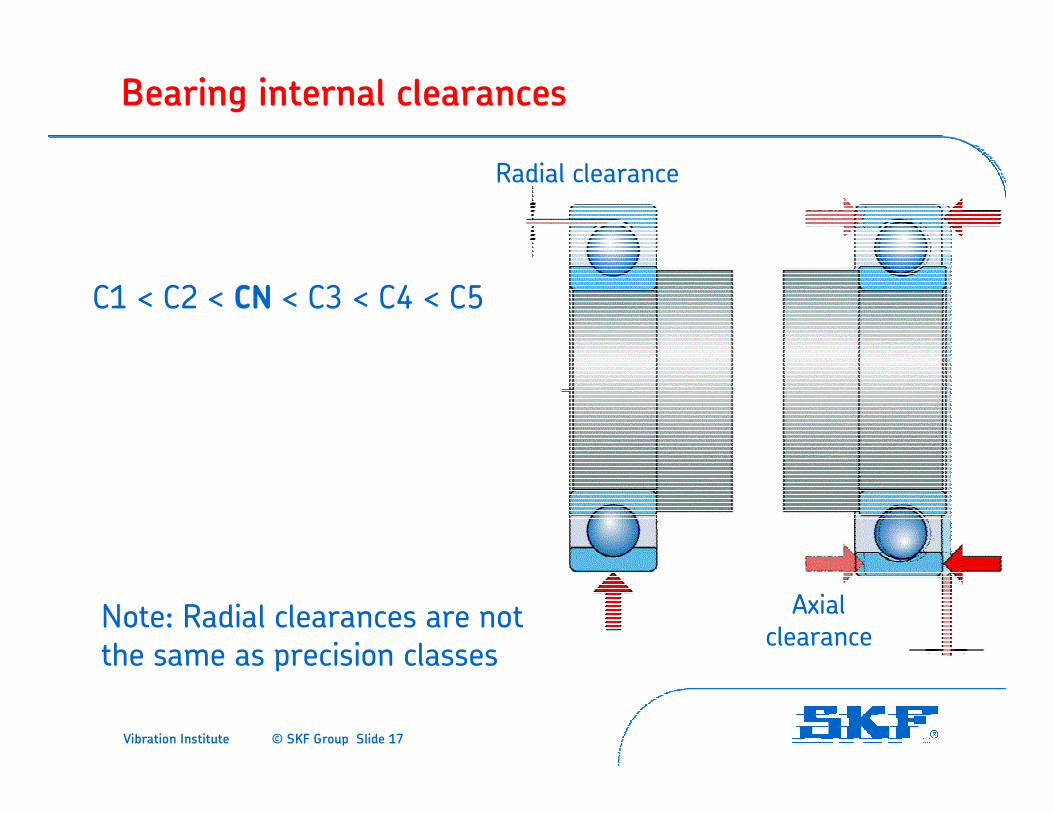
Note: Radial clearances are not the same as precision classes
Radial clearance
Axialclearance
Bearing internal clearances
C1 < C2 < CN < C3 < C4 < C5
Vibration Institute © SKF Group Slide 18
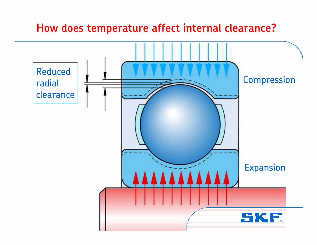
How does temperature affect internal clearance?
Reducedradialclearance
Expansion
Compression
Vibration Institute © SKF Group Slide 19
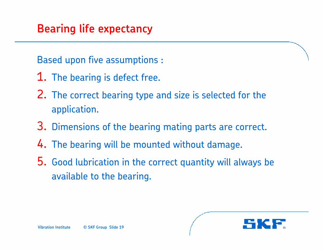
Bearing life expectancy
Based upon five assumptions :
1. The bearing is defect free.
2. The correct bearing type and size is selected for the application.
3. Dimensions of the bearing mating parts are correct.
4. The bearing will be mounted without damage.
5. Good lubrication in the correct quantity will always be available to the bearing.
Vibration Institute © SKF Group Slide 20
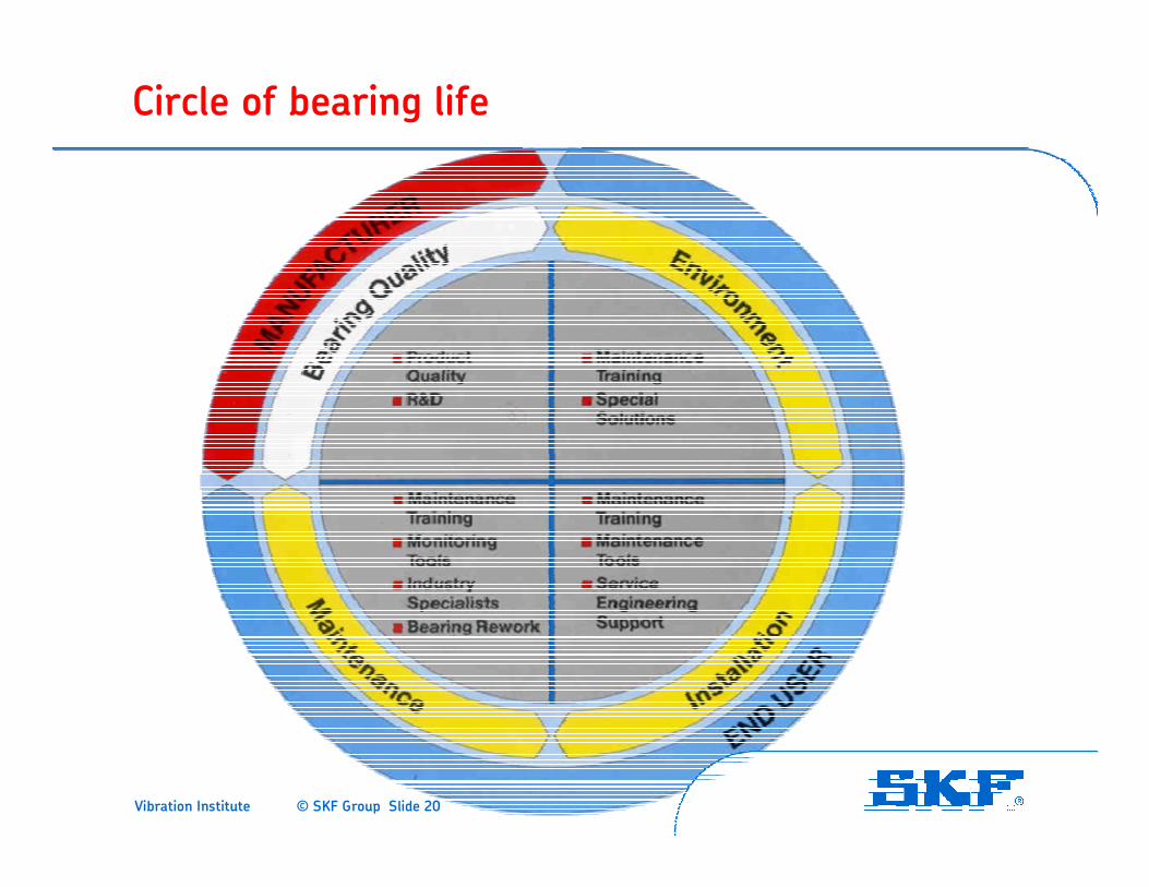
Circle of bearing life
Vibration Institute © SKF Group Slide 21
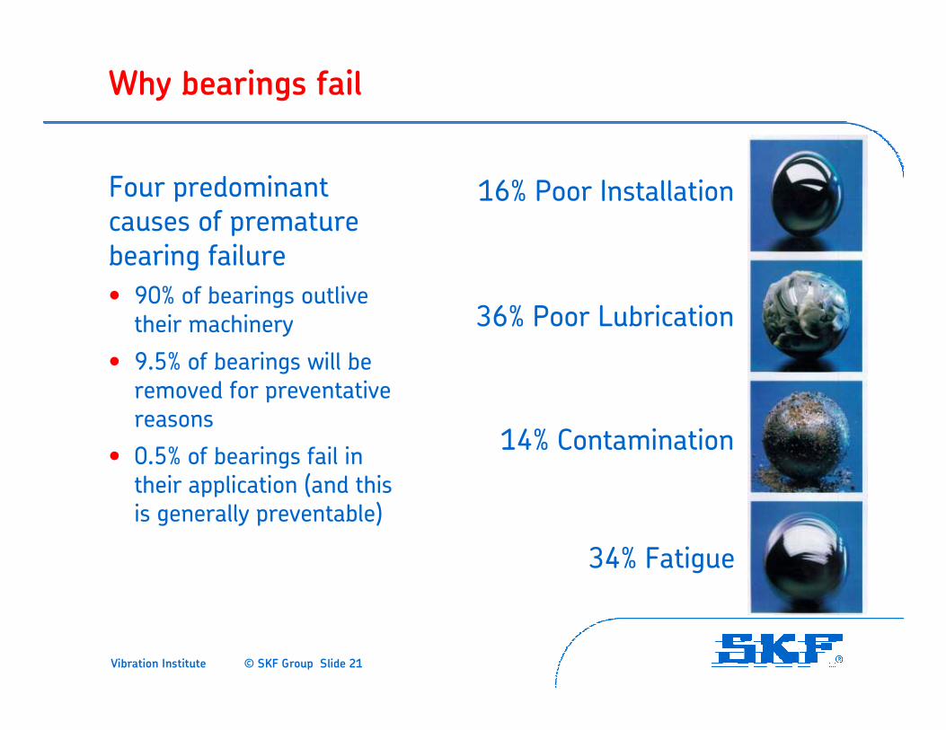
Why bearings fail
Four predominant causes of premature bearing failure
• 90% of bearings outlive their machinery
• 9.5% of bearings will be removed for preventative reasons
• 0.5% of bearings fail in their application (and this is generally preventable)
16% Poor Installation
36% Poor Lubrication
14% Contamination
34% Fatigue
Vibration Institute © SKF Group Slide 22
Pre-operational damage mode causes
• Damage during transportation, handling and storage.
• Incorrect shaft and housing fits.
• Defective bearing seats on shafts and in housings.
• Faulty mounting practices.
• Static misalignment.
• Passage of electric current through the bearing.
Vibration Institute © SKF Group Slide 23
Operational damage mode causes
• Static vibration
• Operational misalignment
• Ineffective sealing
• Ineffective or inadequate lubrication
• Passage of electric current through the bearing
• Excessive loading
Vibration Institute © SKF Group Slide 24
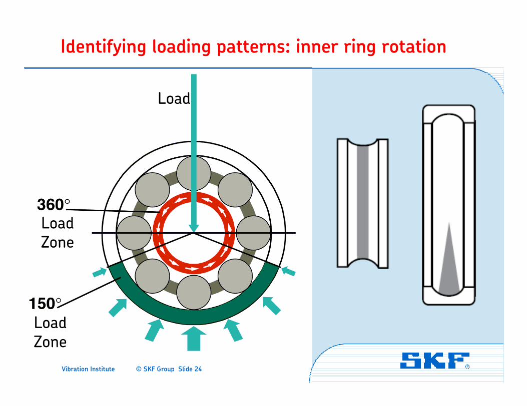
Identifying loading patterns: inner ring rotation
LoadZone
LoadZone
Load
Vibration Institute © SKF Group Slide 25
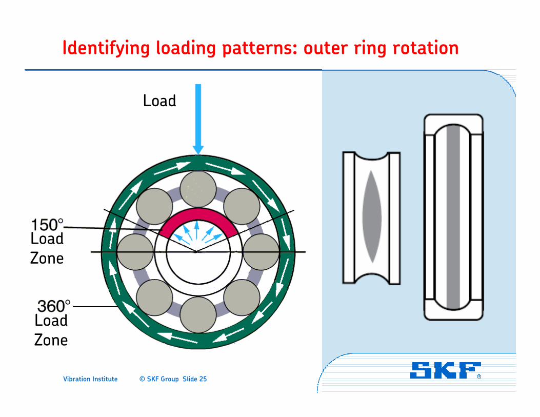
Identifying loading patterns: outer ring rotation
LoadZone
LoadZone
Load
Vibration Institute © SKF Group Slide 26
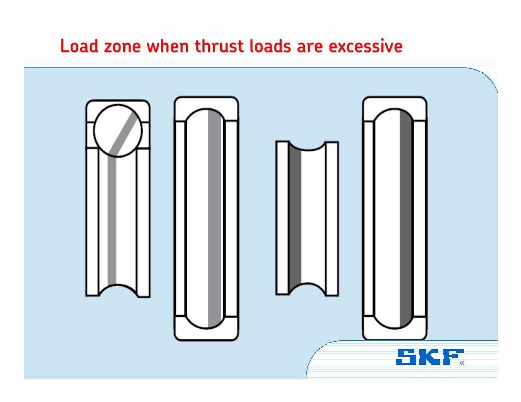
Load zone when thrust loads are excessive
Vibration Institute © SKF Group Slide 27
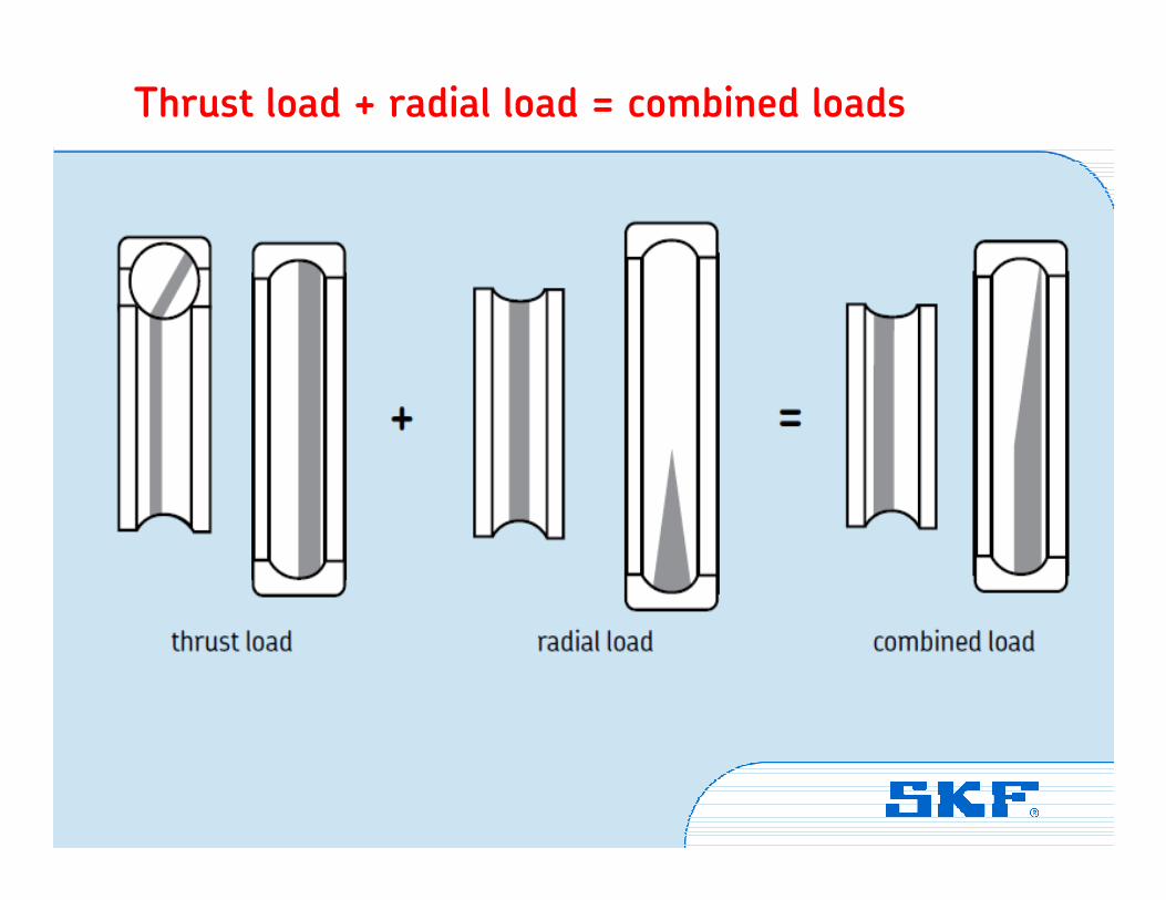
Thrust load + radial load = combined loads
Vibration Institute © SKF Group Slide 28
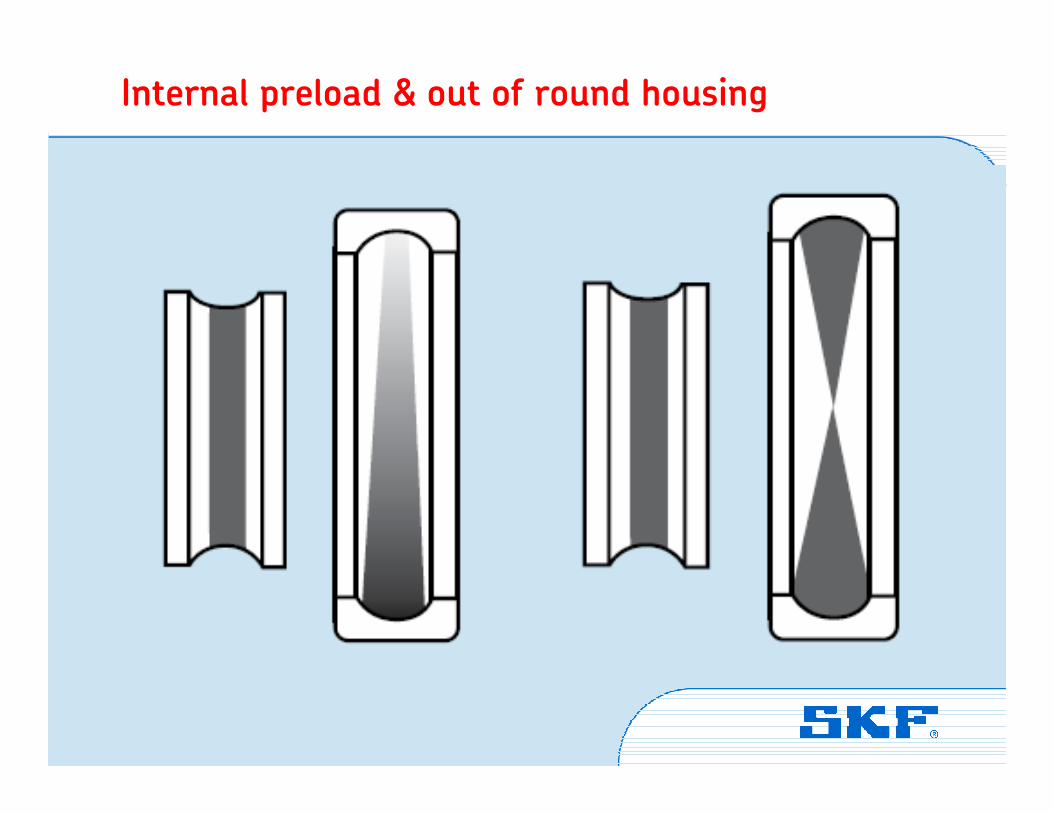
Internal preload & out of round housing
Vibration Institute © SKF Group Slide 29
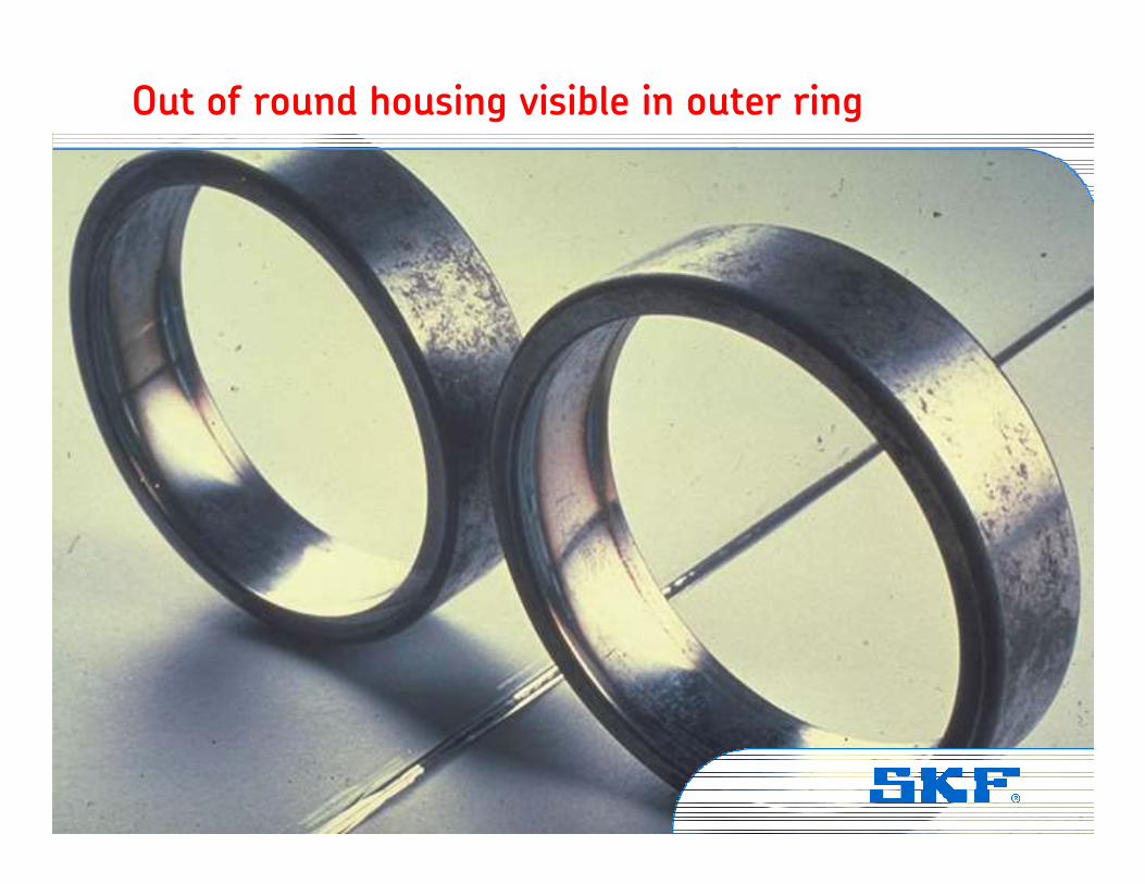
Out of round housing visible in outer ring
Vibration Institute © SKF Group Slide 30
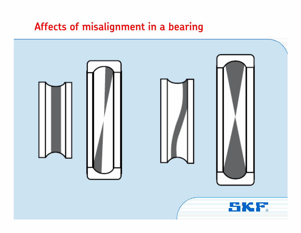
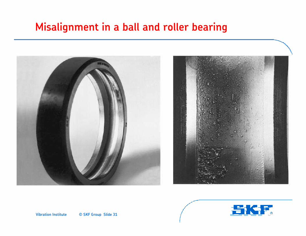
Affects of misalignment in a bearing
Vibration Institute © SKF Group Slide 31
Misalignment in a ball and roller bearing
Vibration Institute © SKF Group Slide 32
Bearing damage
analysis
Vibration Institute © SKF Group Slide 33
Classifications: ISO system
• The ISO classification system is divided in six main areas and then further divided into sub-areas.
• Going through the table, 15 categories in total can be observed in which the damage can be classified.
• These categories will be covered, one by one, indicating the features. A number of typical examples are shown.
• There are some other reasons for bearing damage, such as design problems, etc. These are not classified in the ISO standard.
Vibration Institute © SKF Group Slide 34
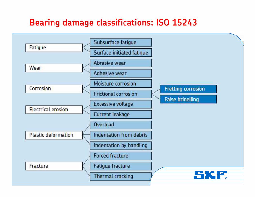
Bearing damage classifications: ISO 15243
Vibration Institute © SKF Group Slide 35
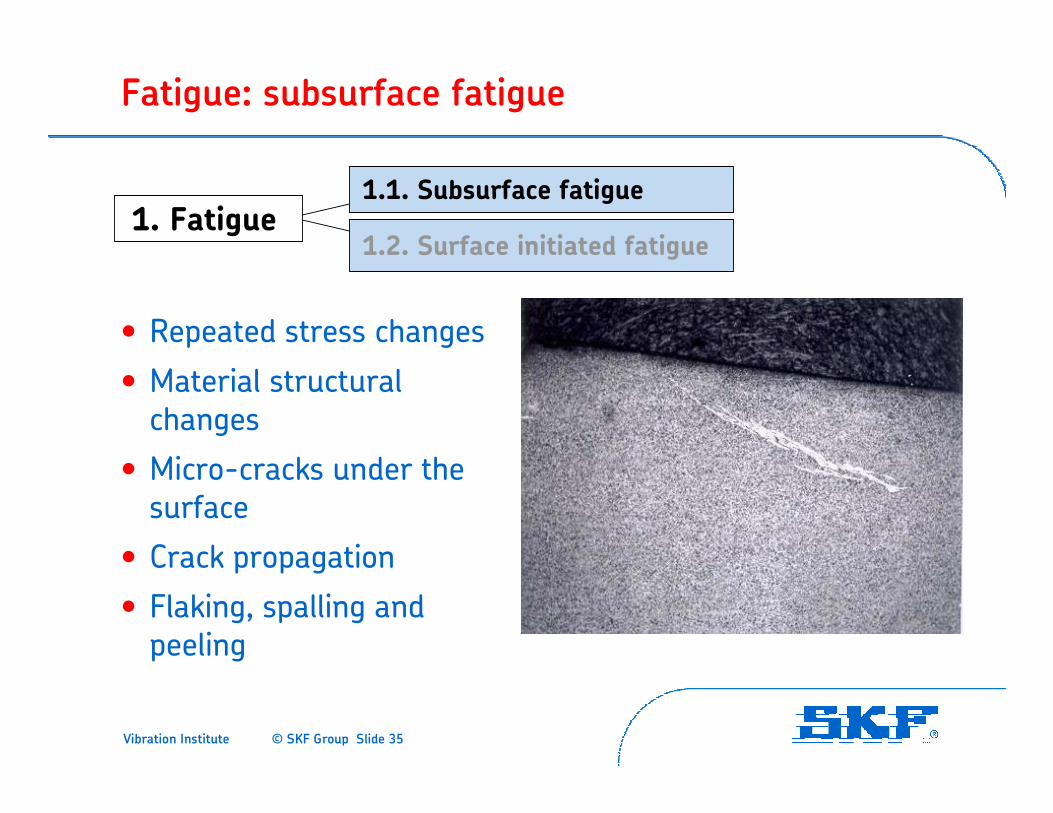
Fatigue: subsurface fatigue
• Repeated stress changes
• Material structural changes
• Micro-cracks under the surface
• Crack propagation
• Flaking, spalling and peeling
1. Fatigue1.1. Subsurface fatigue
1.2. Surface initiated fatigue

Vibration Institute © SKF Group Slide 36
Fatigue: subsurface fatigue
1. Fatigue1.1. Subsurface fatigue
1.2. Surface initiated fatigue
Vibration Institute © SKF Group Slide 37
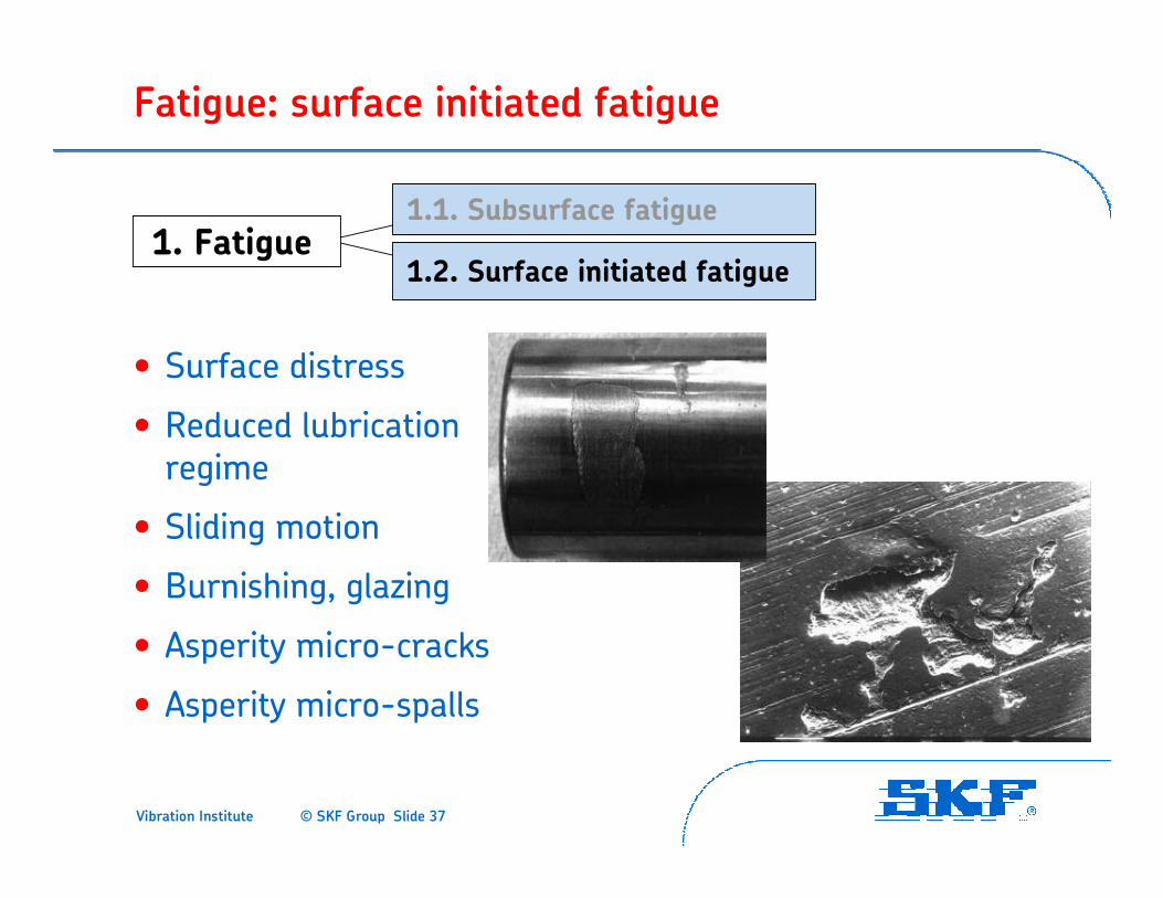
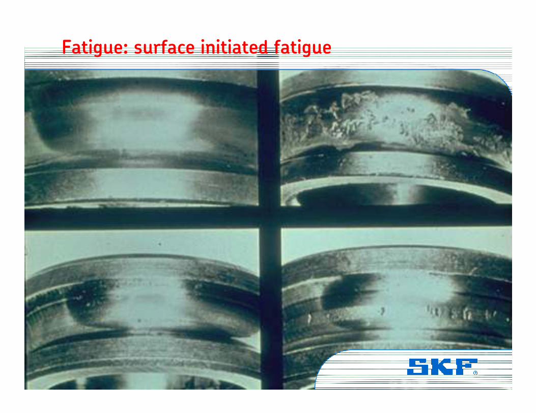
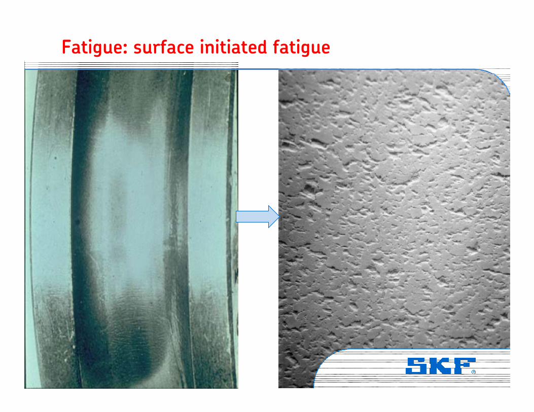
Fatigue: surface initiated fatigue
• Surface distress
• Reduced lubrication regime
• Sliding motion
• Burnishing, glazing
• Asperity micro-cracks
• Asperity micro-spalls
1. Fatigue1.1. Subsurface fatigue
1.2. Surface initiated fatigue
Vibration Institute © SKF Group Slide 38
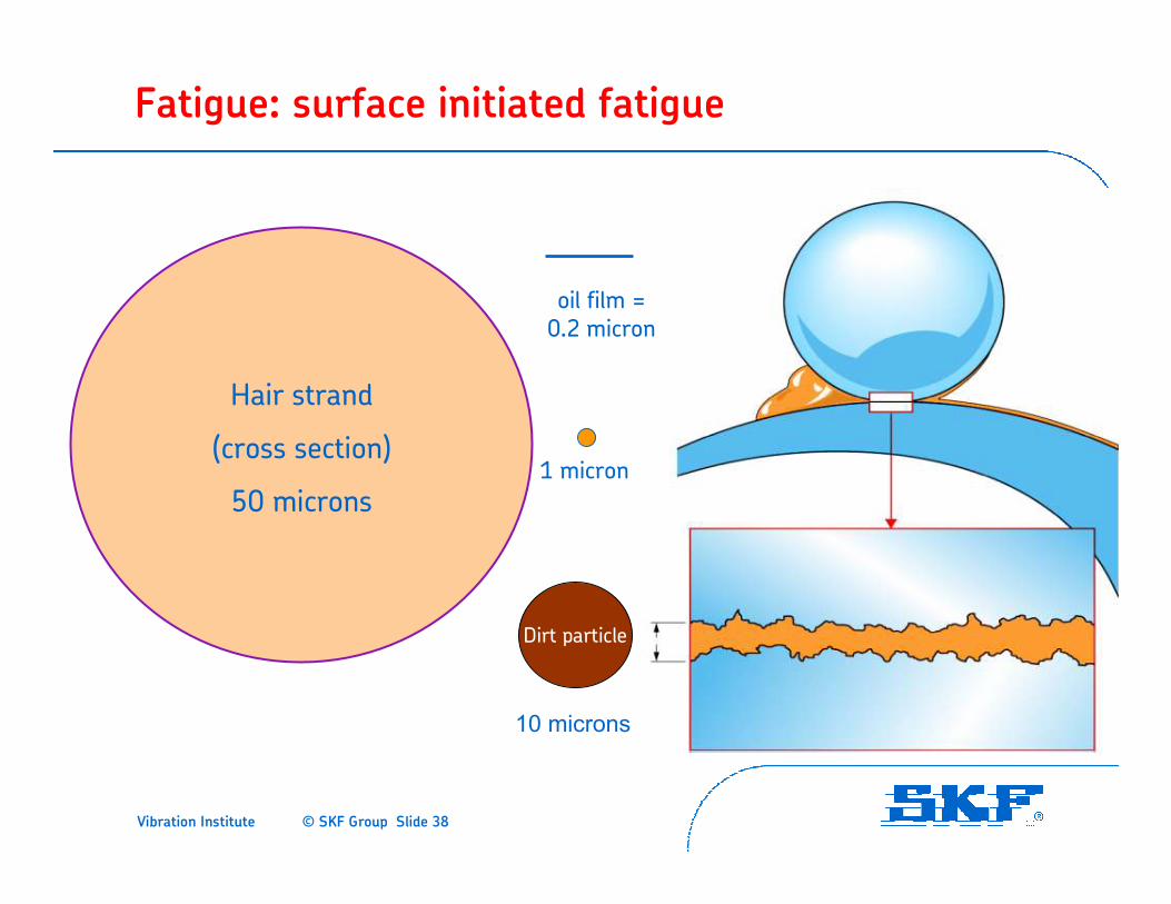
Fatigue: surface initiated fatigue
Hair strand
(cross section)
50 microns
Dirt particle
1 micron
oil film = 0.2 micron
10 microns
Vibration Institute © SKF Group Slide 39
Fatigue: surface initiated fatigue
1. Fatigue1.1. Subsurface fatigue
1.2. Surface initiated fatigue
Vibration Institute © SKF Group Slide 40
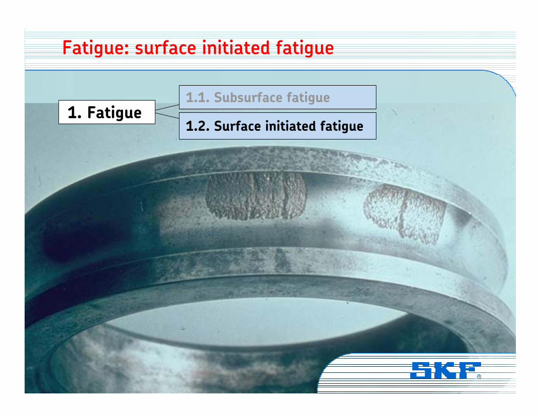
Fatigue: surface initiated fatigue
Vibration Institute © SKF Group Slide 41
Fatigue: surface initiated fatigue
Vibration Institute © SKF Group Slide 42
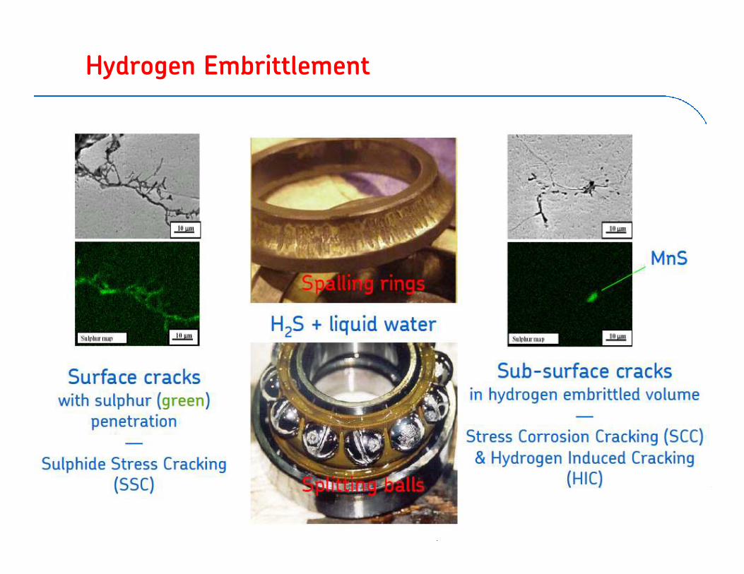
Hydrogen Embrittlement

Vibration Institute © SKF Group Slide 43
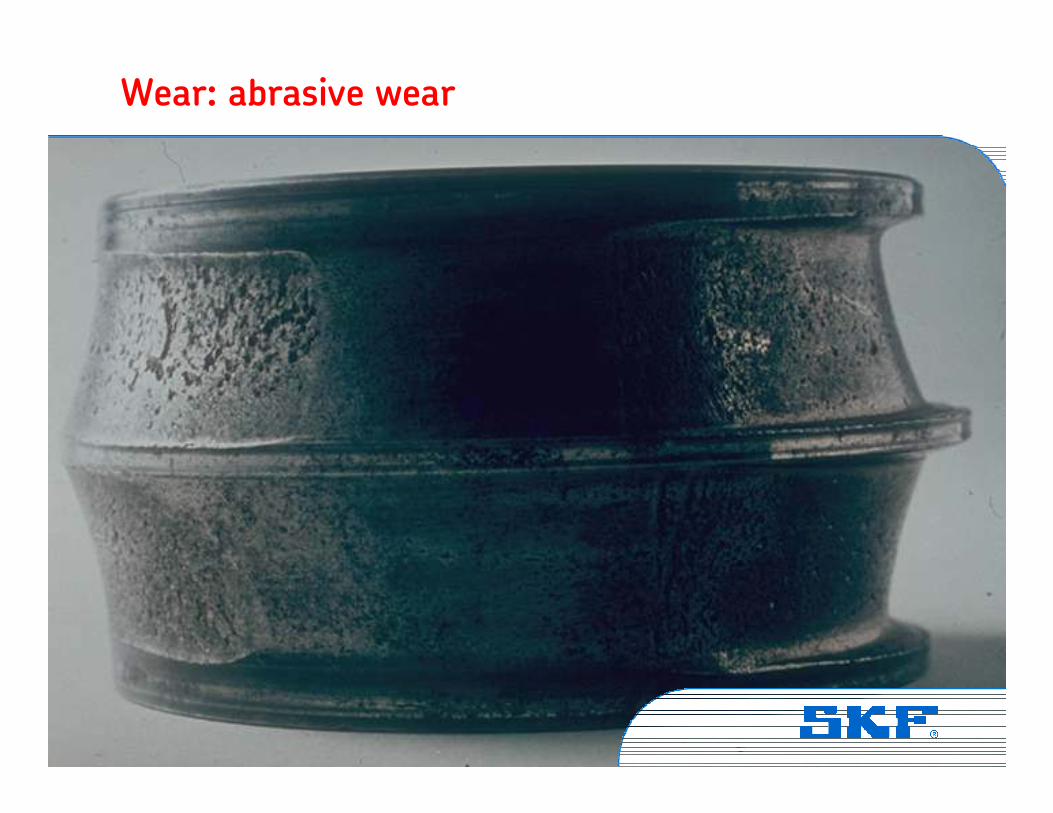
Wear: abrasive wear
• Progressive removal of material
• Ingress of dirt particles
• Accelerating process
• Dull surfaces
2. Wear2.1. Abrasive wear
2.2. Adhesive wear

Vibration Institute © SKF Group Slide 44
Wear: abrasive wear
2. Wear2.1. Abrasive wear
2.2. Adhesive wear
Vibration Institute © SKF Group Slide 45
Wear: abrasive wear
Vibration Institute © SKF Group Slide 46
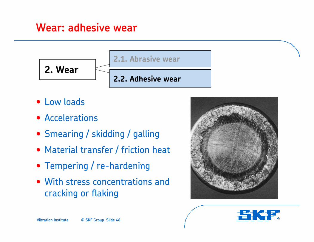
Wear: adhesive wear
• Low loads
• Accelerations
• Smearing / skidding / galling
• Material transfer / friction heat
• Tempering / re-hardening
• With stress concentrations and cracking or flaking
2. Wear2.1. Abrasive wear
2.2. Adhesive wear
Vibration Institute © SKF Group Slide 47
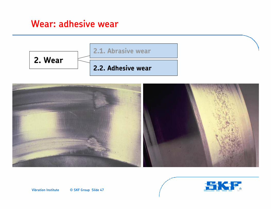
Wear: adhesive wear
2. Wear2.1. Abrasive wear
2.2. Adhesive wear
Vibration Institute © SKF Group Slide 48
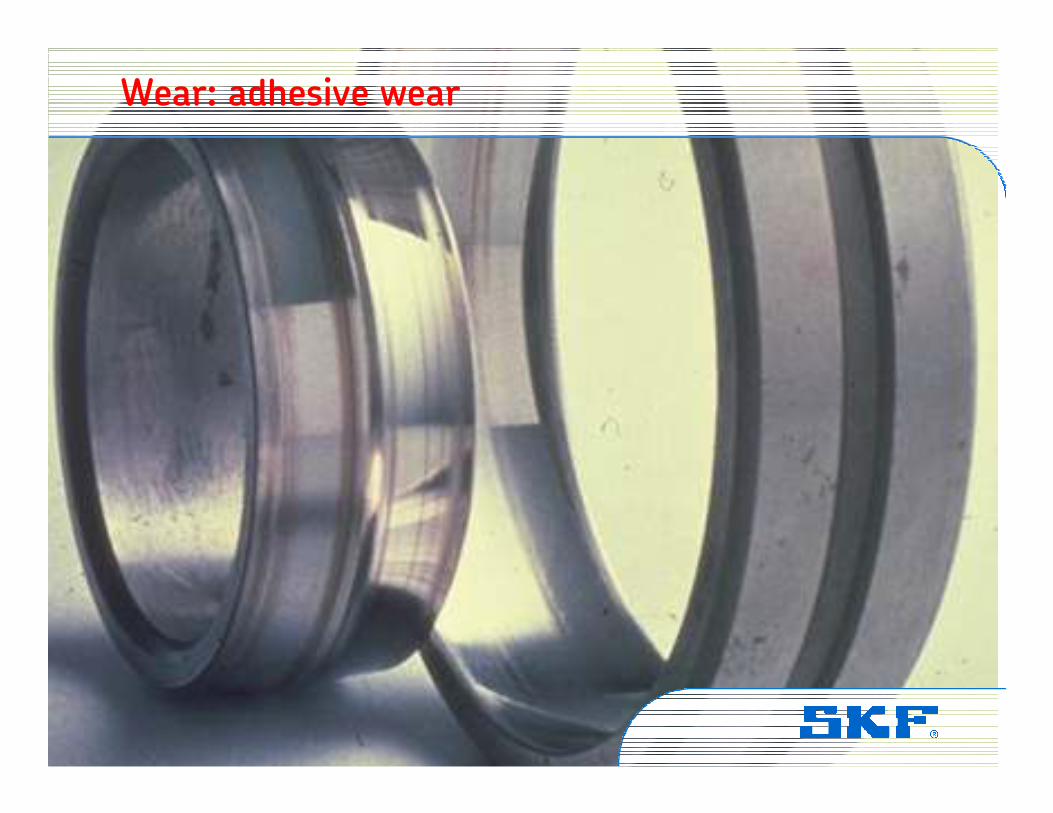
Wear: adhesive wear
Vibration Institute © SKF Group Slide 49
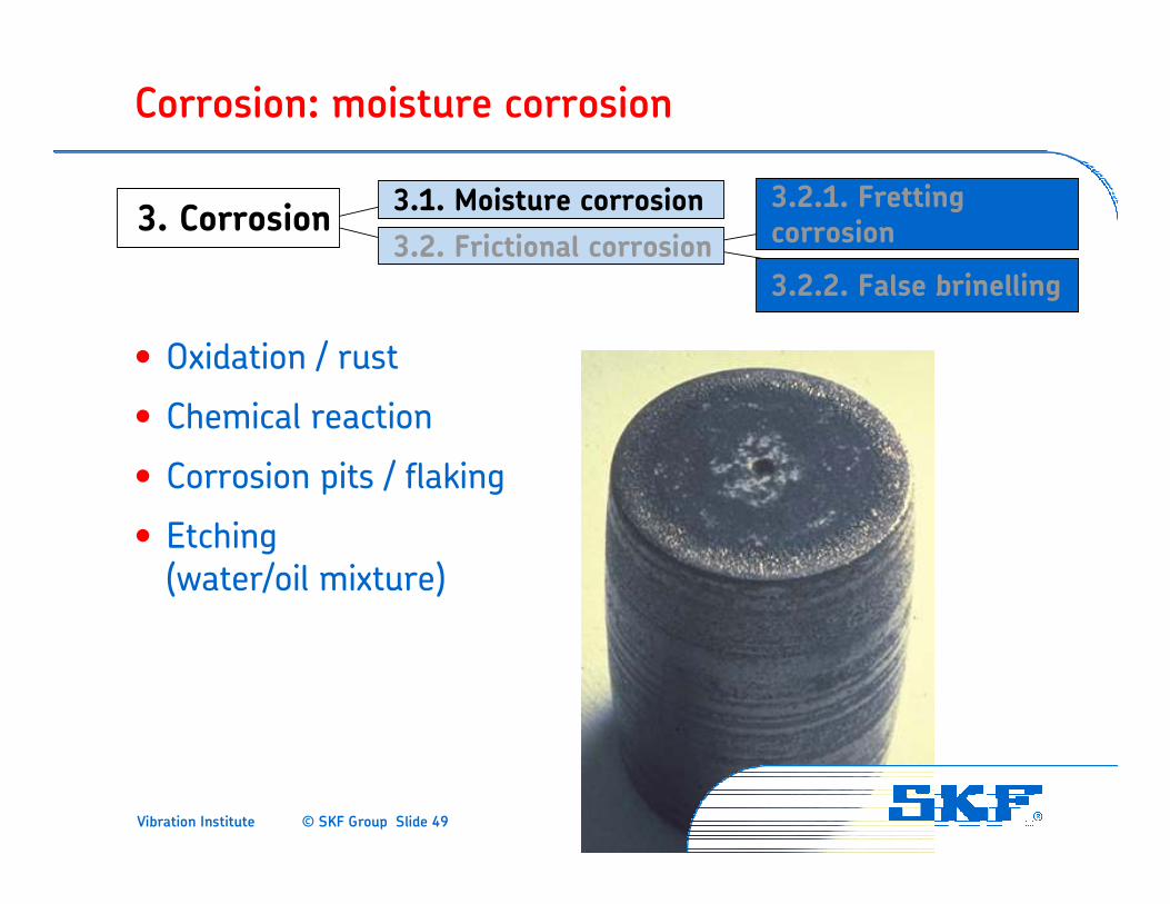
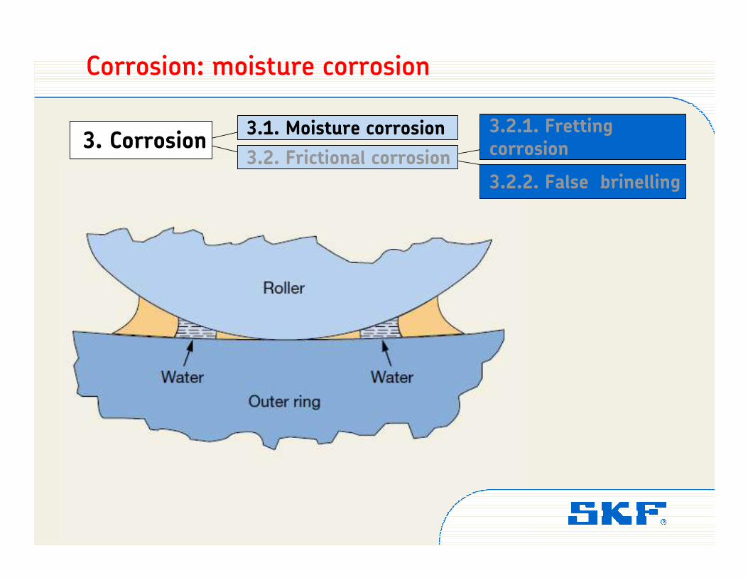
Corrosion: moisture corrosion
3. Corrosion3.2.1. Fretting corrosion
3.1. Moisture corrosion
3.2. Frictional corrosion
3.2.2. False brinelling
• Oxidation / rust
• Chemical reaction
• Corrosion pits / flaking
• Etching (water/oil mixture)
Vibration Institute © SKF Group Slide 50
Corrosion: moisture corrosion
3. Corrosion3.2.1. Fretting corrosion
3.1. Moisture corrosion
3.2. Frictional corrosion
3.2.2. False brinelling

Vibration Institute © SKF Group Slide 51
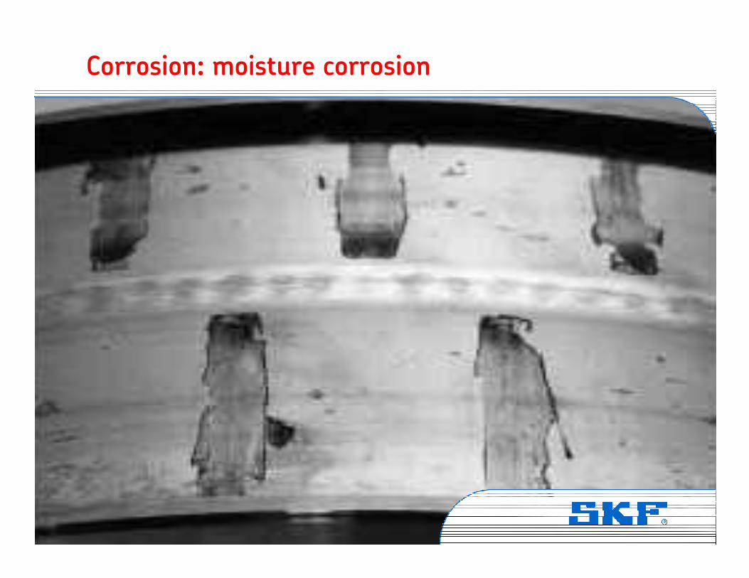
Corrosion: moisture corrosion
3. Corrosion3.2.1. Fretting corrosion
3.1. Moisture corrosion
3.2. Frictional corrosion
3.2.2. False brinelling
Vibration Institute © SKF Group Slide 52
Corrosion: moisture corrosion
Vibration Institute © SKF Group Slide 53
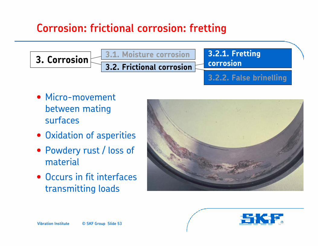
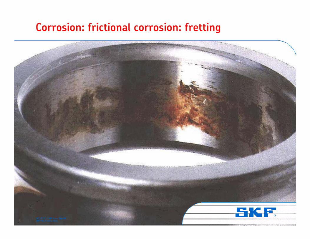
Corrosion: frictional corrosion: fretting
3. Corrosion3.2.1. Fretting corrosion
3.1. Moisture corrosion
3.2. Frictional corrosion
3.2.2. False brinelling
• Micro-movement between mating surfaces
• Oxidation of asperities
• Powdery rust / loss of material
• Occurs in fit interfaces transmitting loads
Vibration Institute © SKF Group Slide 54
Corrosion: frictional corrosion: fretting
3. Corrosion3.2.1. Fretting corrosion
3.1. Moisture corrosion
3.2. Frictional corrosion
3.2.2. False brinelling
Vibration Institute © SKF Group Slide 55
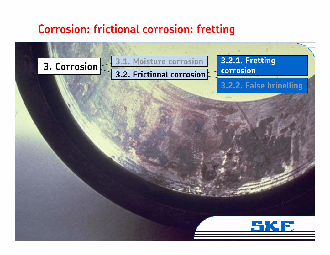
Corrosion: frictional corrosion: fretting
5/13/2011 © SKF Group Slide 55SKF Field Training Series
Vibration Institute © SKF Group Slide 56
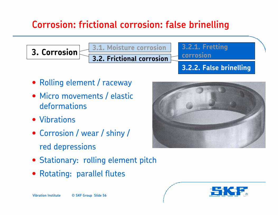
Corrosion: frictional corrosion: false brinelling
3. Corrosion3.2.1. Fretting corrosion
3.1. Moisture corrosion
3.2. Frictional corrosion
3.2.2. False brinelling
• Rolling element / raceway
• Micro movements / elastic deformations
• Vibrations
• Corrosion / wear / shiny /
red depressions
• Stationary: rolling element pitch
• Rotating: parallel flutes
Vibration Institute © SKF Group Slide 57
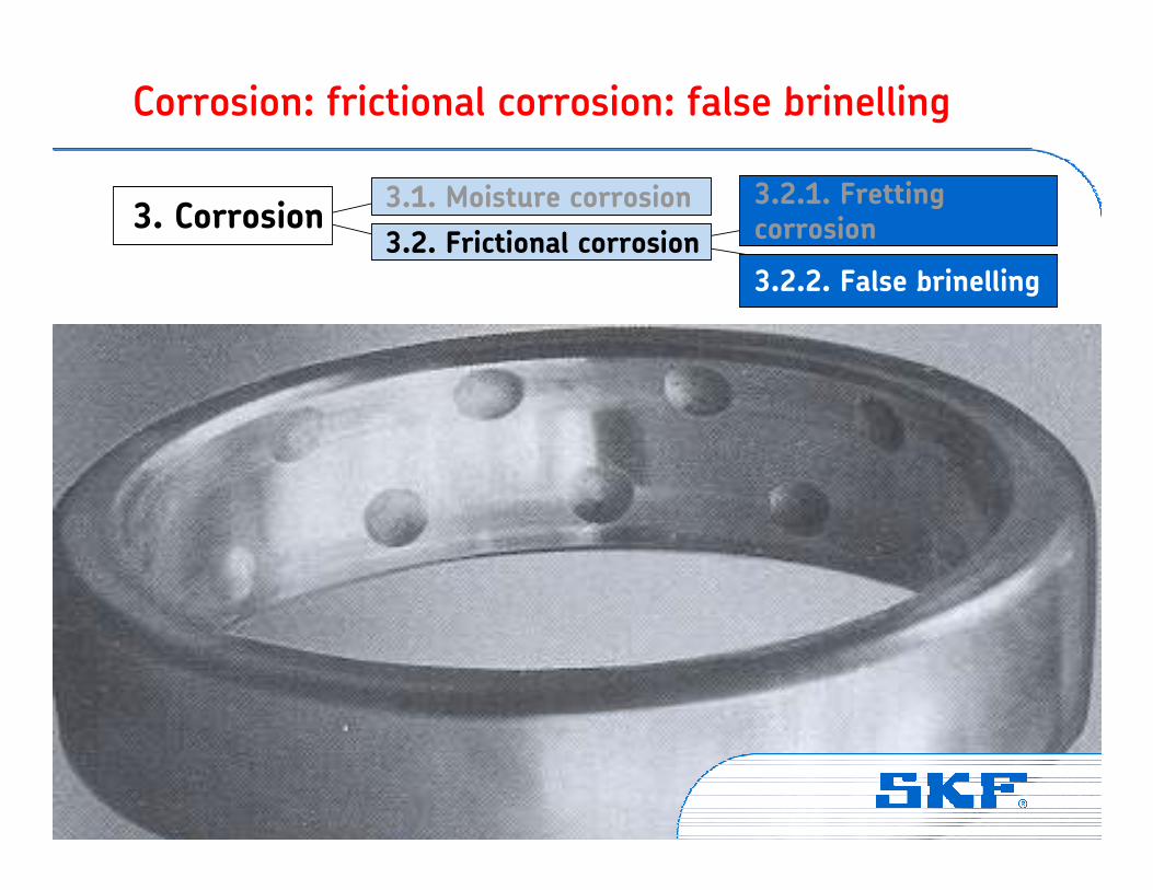
Corrosion: frictional corrosion: false brinelling
3. Corrosion3.2.1. Fretting corrosion
3.1. Moisture corrosion
3.2. Frictional corrosion
3.2.2. False brinelling
Vibration Institute © SKF Group Slide 58
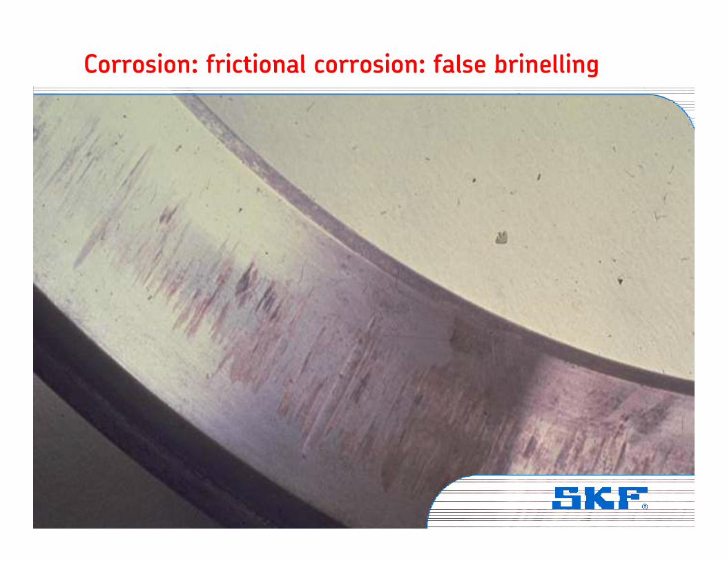
Corrosion: frictional corrosion: false brinelling
Vibration Institute © SKF Group Slide 59
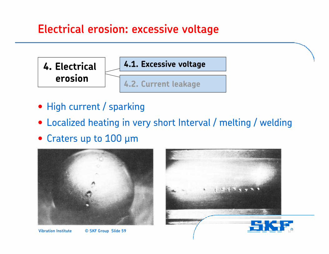
Electrical erosion: excessive voltage
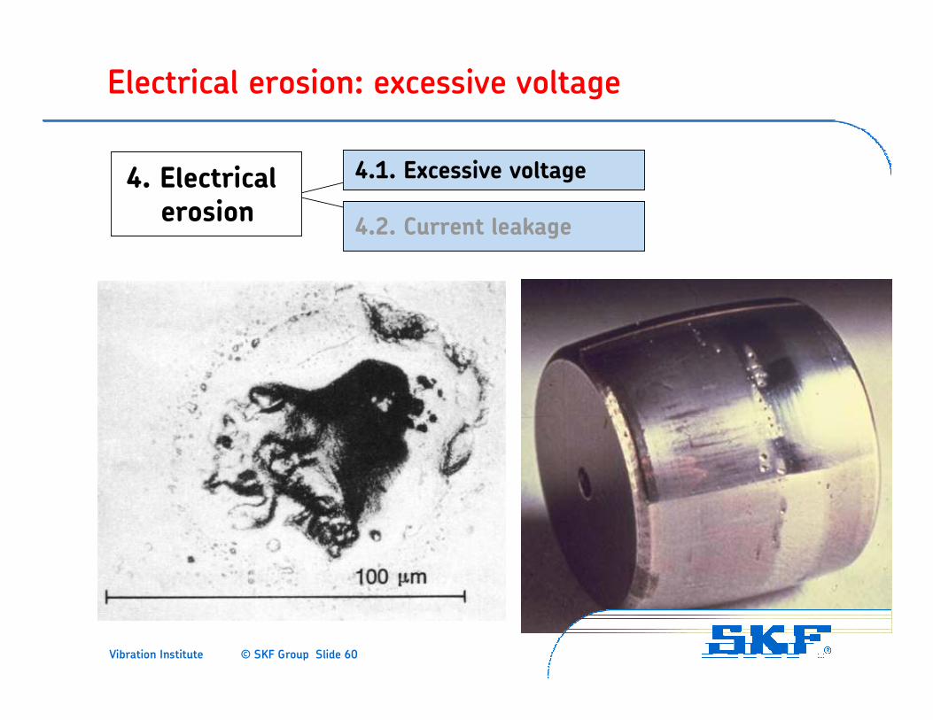
• High current / sparking
• Localized heating in very short Interval / melting / welding
• Craters up to 100 µm
4. Electricalerosion
4.1. Excessive voltage
4.2. Current leakage
Vibration Institute © SKF Group Slide 60
Electrical erosion: excessive voltage
4. Electricalerosion
4.1. Excessive voltage
4.2. Current leakage

Vibration Institute © SKF Group Slide 61
Electrical erosion: excessive voltage
Vibration Institute © SKF Group Slide 62
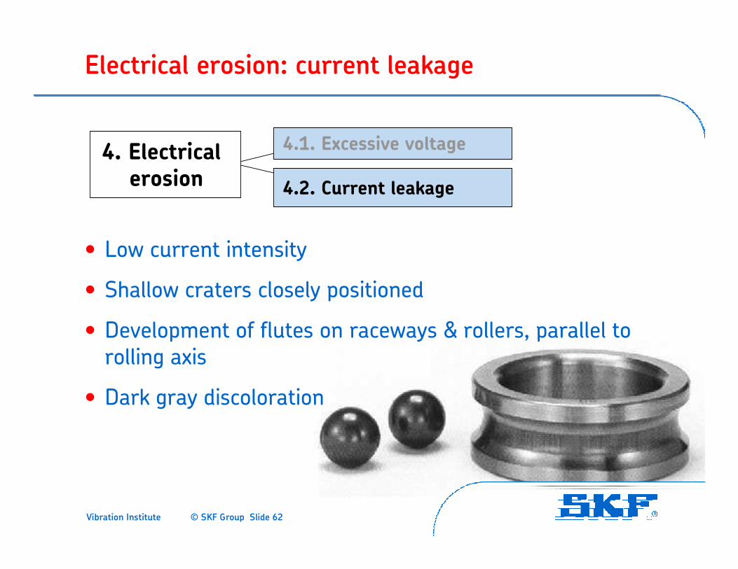
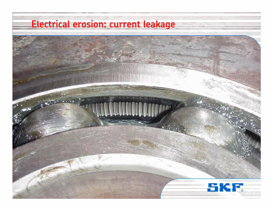
Electrical erosion: current leakage
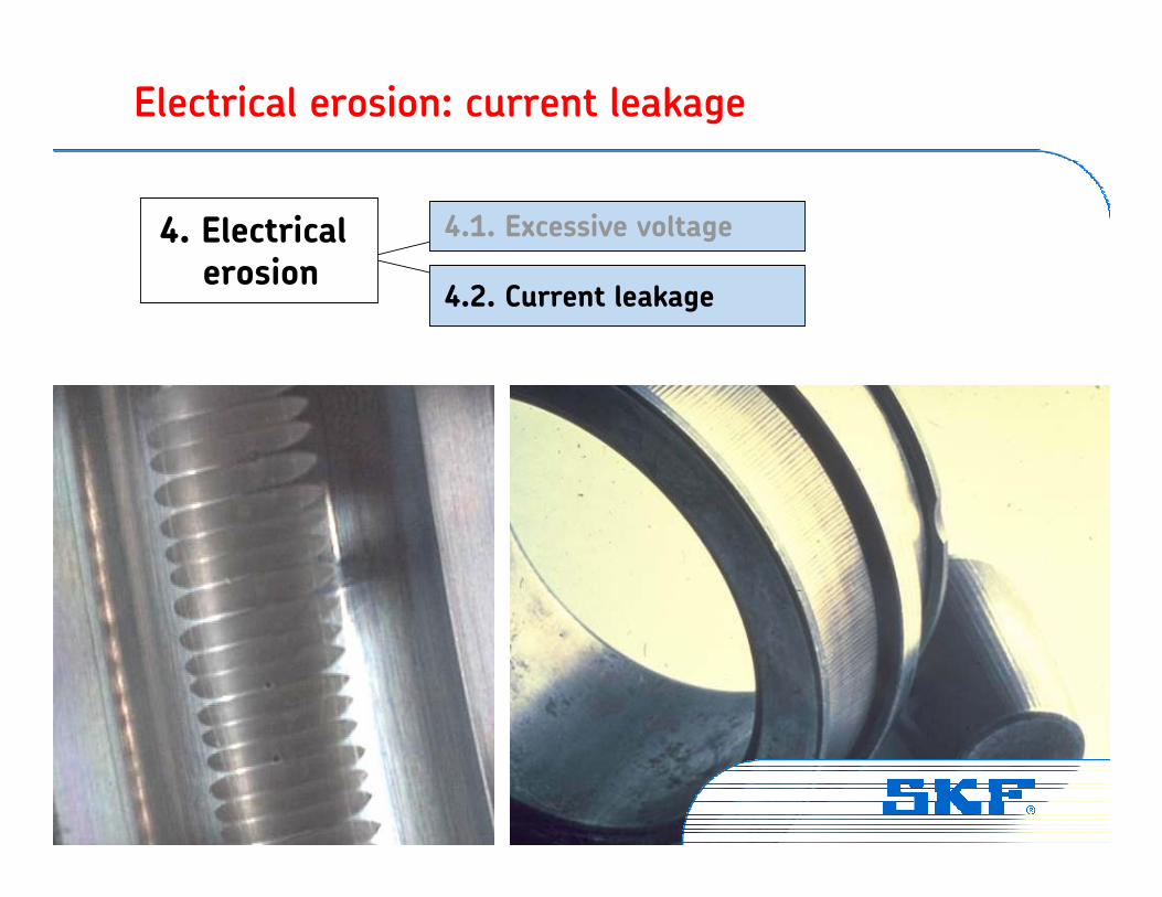
• Low current intensity
• Shallow craters closely positioned
• Development of flutes on raceways & rollers, parallel to rolling axis
• Dark gray discoloration
4. Electricalerosion
4.1. Excessive voltage
4.2. Current leakage
Vibration Institute © SKF Group Slide 63
Electrical erosion: current leakage
4. Electricalerosion
4.1. Excessive voltage
4.2. Current leakage
Vibration Institute © SKF Group Slide 64
Electrical erosion: current leakage
Vibration Institute © SKF Group Slide 65
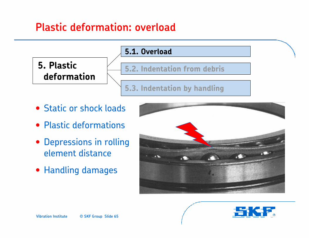
Plastic deformation: overload
• Static or shock loads
• Plastic deformations
• Depressions in rolling element distance
• Handling damages
5. Plasticdeformation
5.1. Overload
5.2. Indentation from debris
5.3. Indentation by handling
Vibration Institute © SKF Group Slide 66
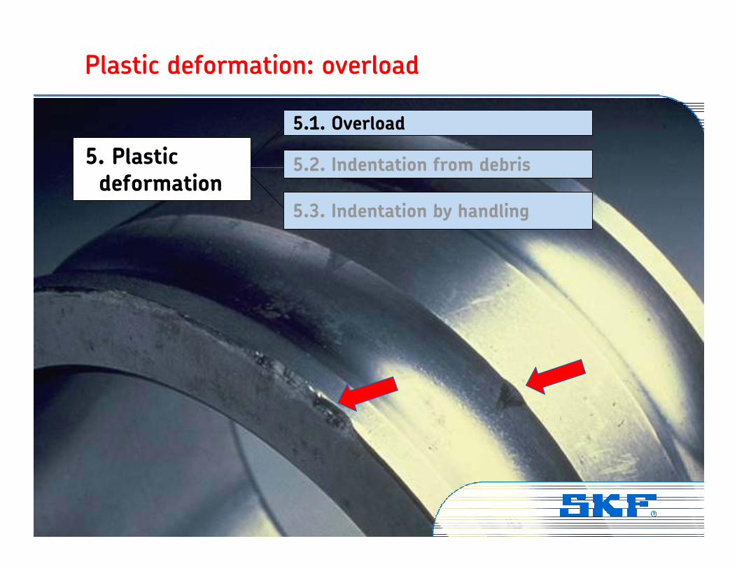
Plastic deformation: overload
5. Plasticdeformation
5.1. Overload
5.2. Indentation from debris
5.3. Indentation by handling
Vibration Institute © SKF Group Slide 67
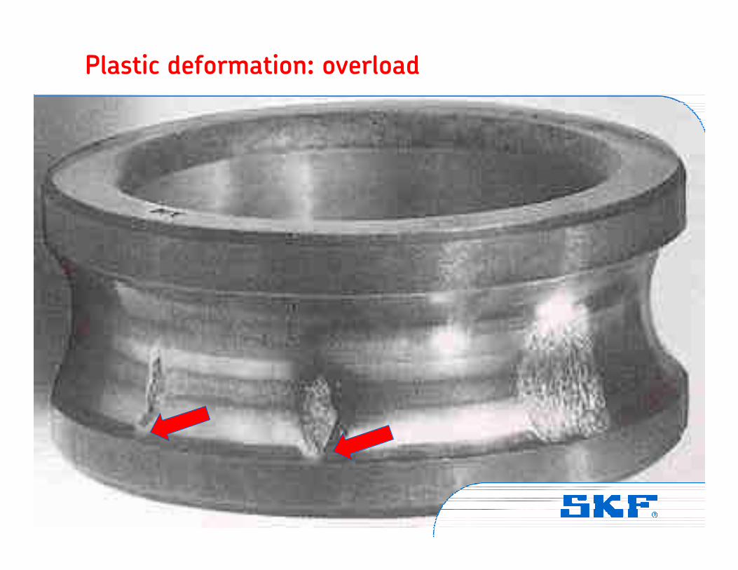
Plastic deformation: overload
Vibration Institute © SKF Group Slide 68
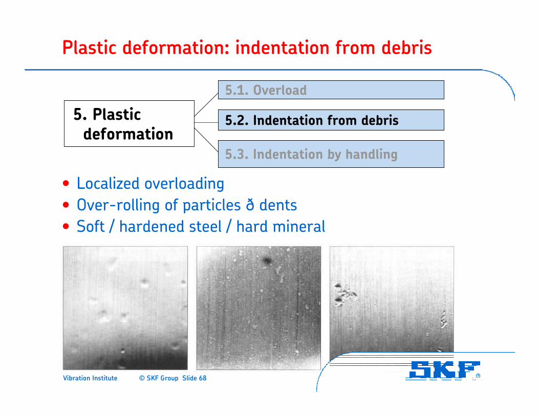
Plastic deformation: indentation from debris
• Localized overloading
• Over-rolling of particles ð dents
• Soft / hardened steel / hard mineral
5. Plasticdeformation
5.1. Overload
5.2. Indentation from debris
5.3. Indentation by handling
Vibration Institute © SKF Group Slide 69
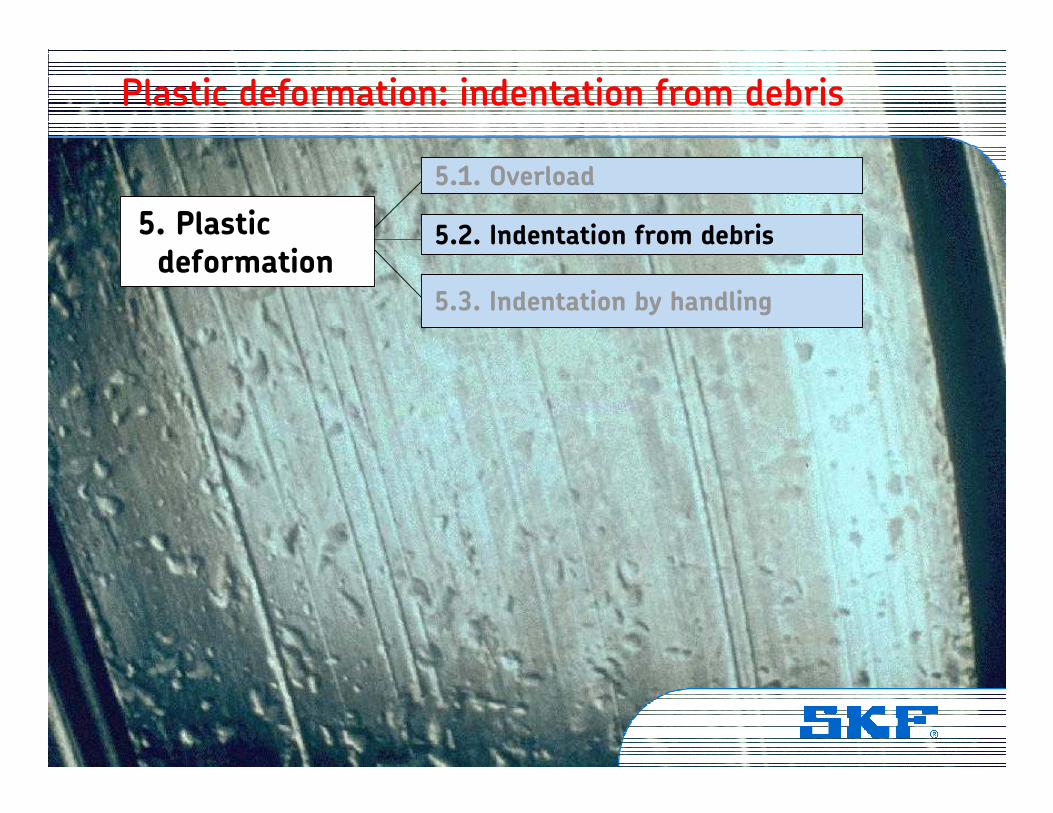
Plastic deformation: indentation from debris
5. Plasticdeformation
5.1. Overload
5.2. Indentation from debris
5.3. Indentation by handling
Vibration Institute © SKF Group Slide 70
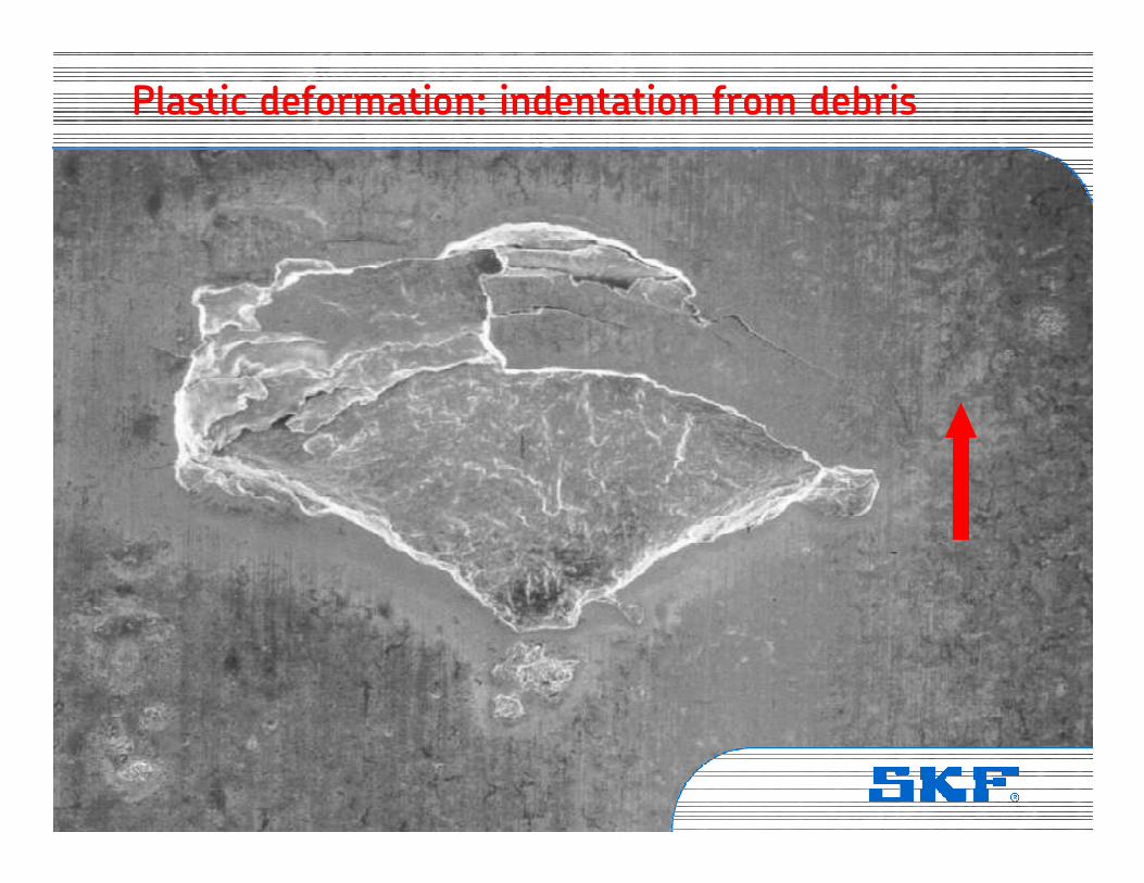
Plastic deformation: indentation from debris
Vibration Institute © SKF Group Slide 71
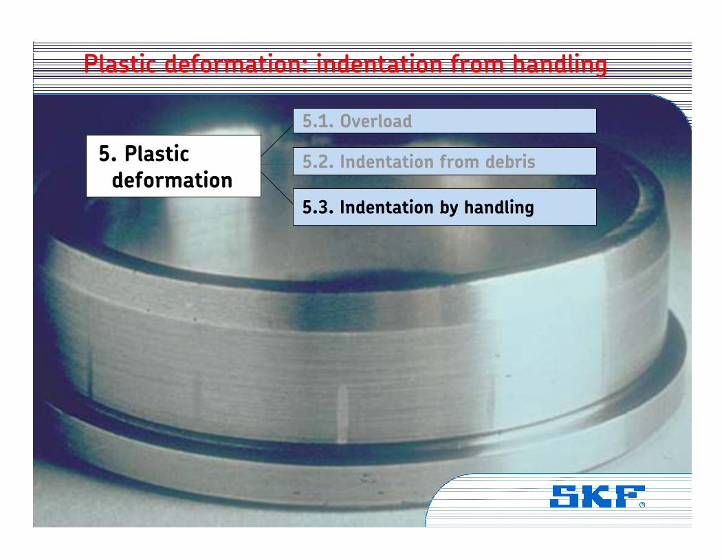
Plastic deformation: indentation from handling
5. Plasticdeformation
5.1. Overload
5.2. Indentation from debris
5.3. Indentation by handling
Vibration Institute © SKF Group Slide 72
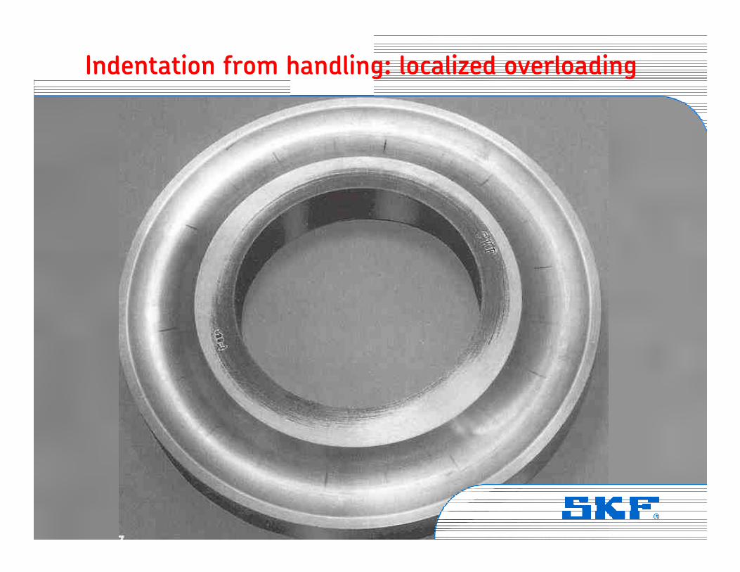
Indentation from handling: localized overloading
Vibration Institute © SKF Group Slide 73
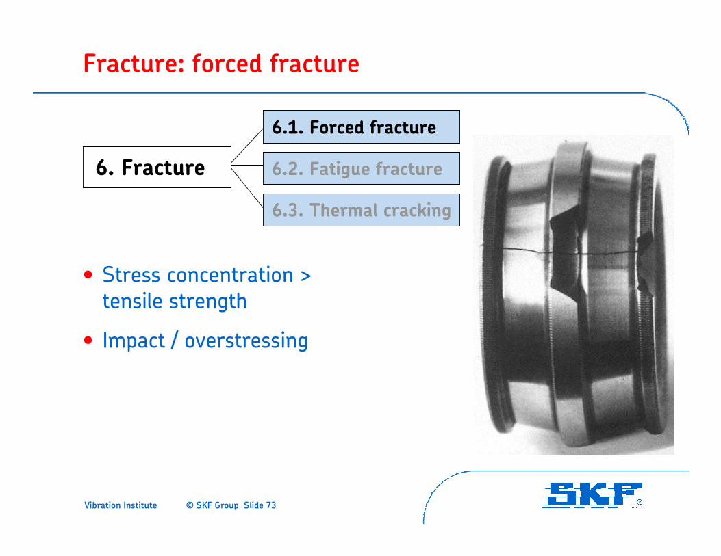
Fracture: forced fracture
• Stress concentration > tensile strength
• Impact / overstressing
6. Fracture
6.1. Forced fracture
6.2. Fatigue fracture
6.3. Thermal cracking
Vibration Institute © SKF Group Slide 74
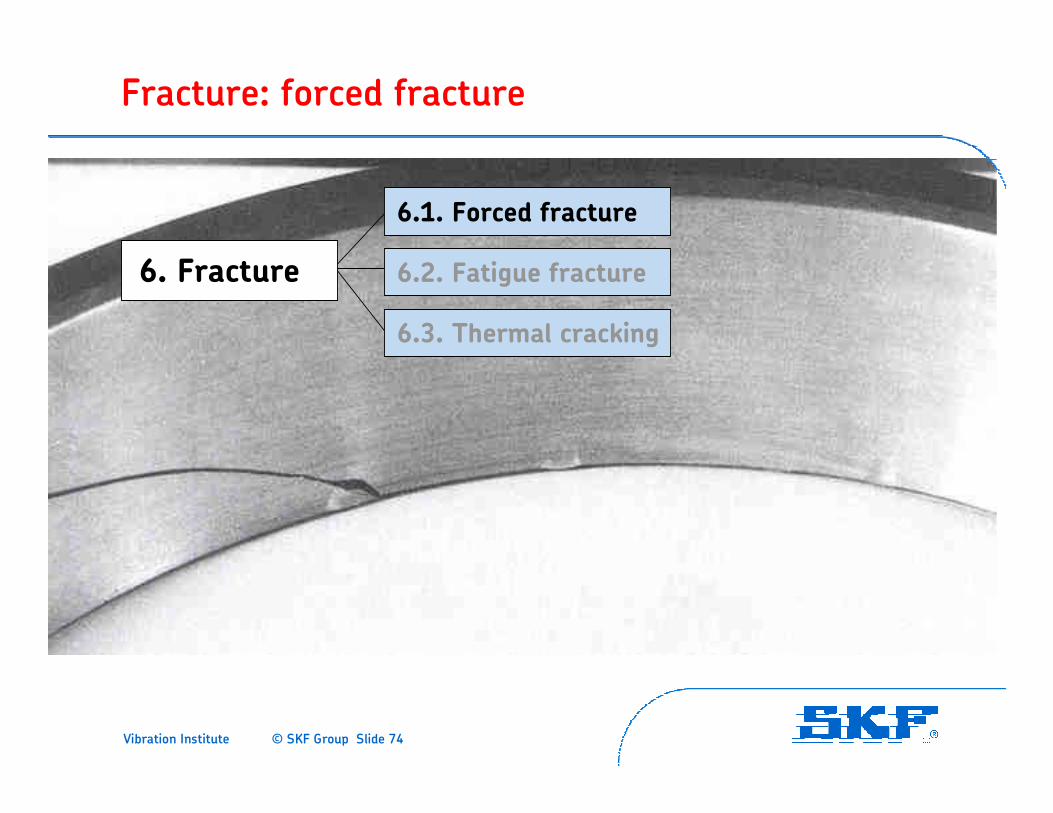
Fracture: forced fracture
6. Fracture
6.1. Forced fracture
6.2. Fatigue fracture
6.3. Thermal cracking

Vibration Institute © SKF Group Slide 75
Fracture: forced fracture
Vibration Institute © SKF Group Slide 76
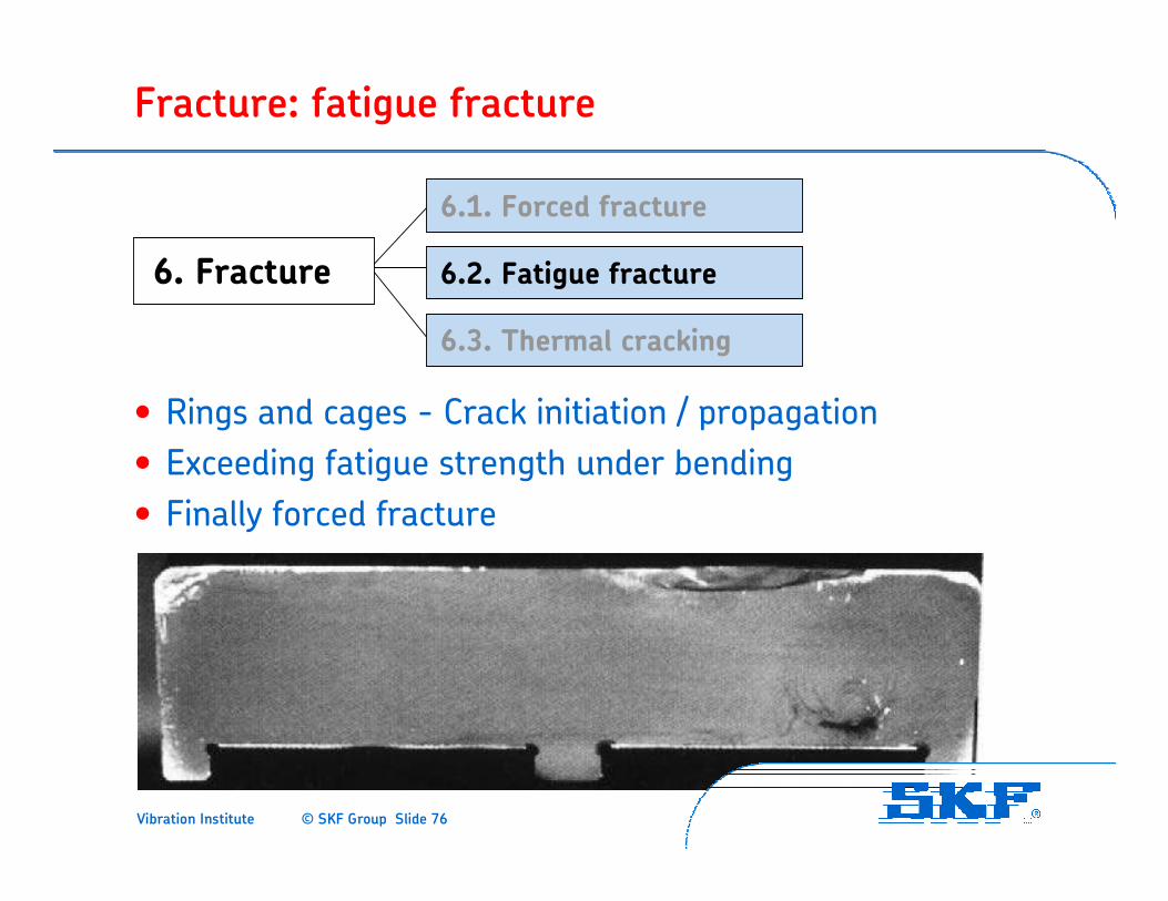
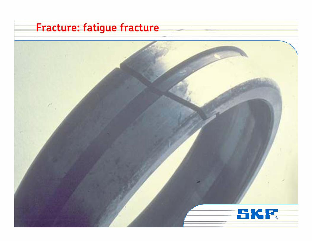
Fracture: fatigue fracture
• Rings and cages - Crack initiation / propagation
• Exceeding fatigue strength under bending
• Finally forced fracture
6. Fracture
6.1. Forced fracture
6.2. Fatigue fracture
6.3. Thermal cracking
Vibration Institute © SKF Group Slide 77
Fracture: fatigue fracture
Vibration Institute © SKF Group Slide 78
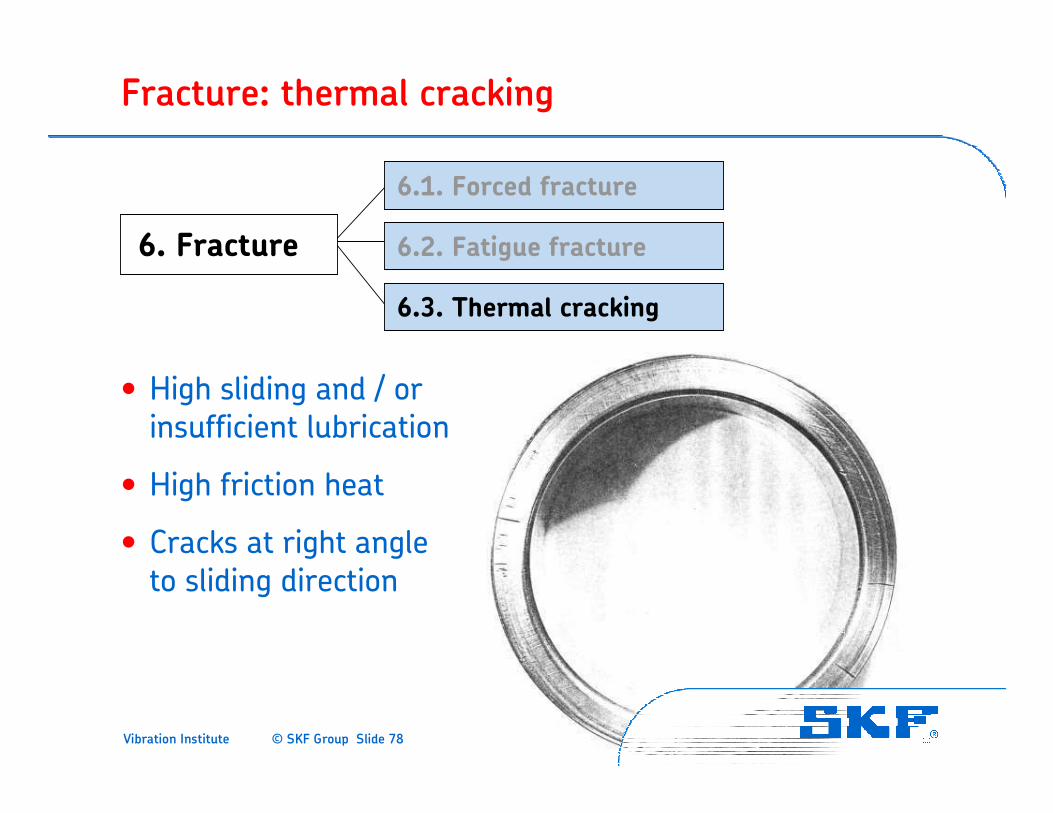
Fracture: thermal cracking
• High sliding and / or insufficient lubrication
• High friction heat
• Cracks at right angle to sliding direction
6. Fracture
6.1. Forced fracture
6.2. Fatigue fracture
6.3. Thermal cracking
Vibration Institute © SKF Group Slide 79
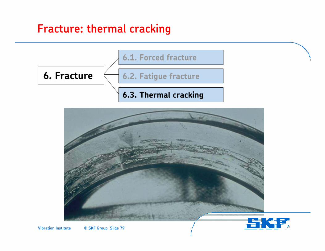
Fracture: thermal cracking
6. Fracture
6.1. Forced fracture
6.2. Fatigue fracture
6.3. Thermal cracking
Vibration Institute © SKF Group Slide 80
Classifications: securing evidence
• Collect operating data, monitoring data
• Collect lubricant samples
• Check bearing environment
• Assess bearing in mounted condition
• Mark mounting position
• Remove, mark and bag bearing and parts
• Check bearing seats
• Lubricant condition (color, presence of water, viscosity, consistency, distribution in the bearing, etc.)
Vibration Institute © SKF Group Slide 81
Classifications: conducting the analysis
• Examine bearing and parts
• Record visual observations
• Record pictures of bearing and pertinent parts
• Use the failure modes to eliminate improbable causes and determine the original cause of the failure
• Use external resources such as SKF Bearing Inspector at @ptitudeXchange.com or SKF Bearing Installation and Maintenance Guide #140-710
• Contact external resources for assistance, if needed
• Initiate corrective action, if desired.
• Consider SKF analysis services ($)
Vibration Institute © SKF Group Slide 82
Available training courses
• WE201: Bearing Maintenance and Technology
• WE202: Bearing in Rotating Machinery Applications
• WE203: Lubrication in Rolling Element Bearings
•WE204: Root Cause Bearing Damage Analysis

Vibration Institute © SKF Group Slide 83
Thank you!

Vibration Institute © SKF Group Slide 84