Embed Size (px)
Citation preview
Available online at www.ijpe-online.com
Vol. 13, No. 4, July 2017, pp. 337-347 DOI: 10.23940/ijpe.17.04.p1.337347
Vibration Analysis of Shaft Misalignment and Diagnosis Method of
Structure Faults for Rotating Machinery
Zhaoyi Guana, Peng Chena,*, Xiaoyu Zhanga, Xiong Zhoub, Ke Lic
aDepartment of Biological Resources, Mie University, Mie, 514-8507, Japan
bChongqing University of Science & Technology, China cJiangnan University, China
Abstract
In this paper, two kinds of dynamic models for shaft misalignment of rotating machinery are proposed for vibration analysis and diagnosis
of the shaft misalignment state. In order to obtain the solution of the dynamic models and clarify the vibration signal features measured in
the shaft misalignment state, the calculation method of vibration forces caused by misalignments is also shown. The results of computer
simulation and experiment using the same rotating machine are shown to verify the efficiency of the dynamic analysis method proposed
in this paper. Finally, the method for distinguishing structure faults of rotating machines (shaft misalignment state, unbalance state and
looseness state) is discussed by using symptom parameters and spectra of the vibration signal measured in these states.
Keywords: Diagnostics; condition monitoring; maintenance; rotating machinery; vibration and acoustics
(Submitted on January 9, 2017; Revised on May 16, 2017; Accepted on May 24, 2017)
© 2017 Totem Publisher, Inc. All rights reserved.
1. Introduction
Rotating machinery covers a broad range of mechanical equipment and plays a significant role in industrial applications,
such as wind turbine, pump, blower, power electric generator etc. It generally operates under tough working environments
and is therefore subject to faults [1]. It is very important to ensure that large rotating machinery operates safely and reliably
[2]. Misalignment is one of the most commonly observed faults in rotating machines. It causes improper vibrations and
shortens the life of parts installed on the shaft, such as bearings and gears [3]. Fault detection and type identification of
misalignment states are very important to ensure machine safety and production quality [4,5].
Previous research proposed a variety of analytical methods for mechanical fault diagnosis especially structure faults for
rotating Machinery. However, the reason of the vibration caused by the shaft misalignment cannot be explained by these
methods. Some studies are hard to simulate misalignment states without giving vibration equations [6], some studies have
focused on characteristic parameters of vibration signal while ignoring the characteristics of spectrum [7], and some studies
just focused on the diagnosis methods without explain the mechanism of vibration caused by the shaft misalignment [8]. In
particular, many fault diagnoses on rotating machinery such as wind turbines has focused on abnormal bearings or gears but
ignored the impact caused by abnormalities in the shaft [9,10]. Since the mechanisms of the abnormal vibration caused by
shaft misalignment and the vibration signal features measured for diagnosis have not yet been made clear by theory, the
diagnosis of the shaft misalignment in real-life situations is merely carried out through experience and statistical methods.
Therefore, the accuracy of detecting and distinguishing shaft misalignment state remains too low and needs improvement. In
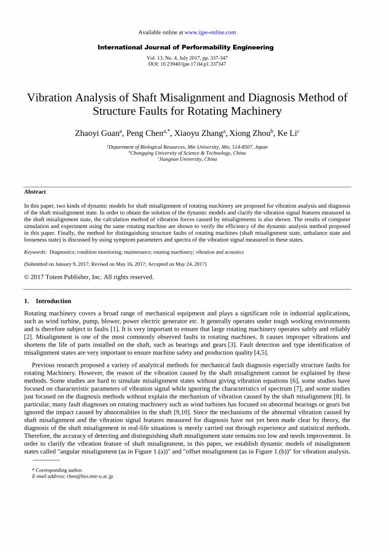
order to clarify the vibration feature of shaft misalignment, in this paper, we establish dynamic models of misalignment
states called "angular misalignment (as in Figure 1.(a))" and "offset misalignment (as in Figure 1.(b))" for vibration analysis.
* Corresponding author.
E-mail address: [email protected]
338 Zhaoyi Guan, Peng Chen, Xiaoyu Zhang, Xiong Zhou, and Ke Li
The vibration equations of misalignment states can be derived through the dynamic models, by which the simulation of
vibration signal on misalignment states can be realized. The feature of fault vibration caused by shaft misalignment was
explained through the spectrum analysis using the data obtained by simulation and experiments. To verify the efficiency of
the dynamic analysis proposed in this paper, we compared the results of computer simulations with experiments.
(a) (b)
Figure 1. Misalignment states of rotating shaft ((a) Angular misalignment (b) Offset misalignment)
The abnormal states of unbalance, misalignment and looseness are called “structural faults” which often occur in rotating
machinery with a feature spectrum in the low frequency area [11]. The features of structural faults resemble each other in
spectrum of vibration signal in many cases and thus are difficult to distinguish from each other [12]. Although some studies
have revealed a variety of spectrum characteristics of abnormal states, they were still not enough to accurately distinguish
the structural faults [13]. Therefore, we propose the distinguishing method for structural faults by using symptom
parameters (SPs) [14] in time domain and spectra of vibration signals according to the simulation and experiment results.
2. Dynamic models for misalignment state
Vibration models of misalignment states such as The Coupling Coordinate System and The Vibration Model with Two
Degrees of Freedom [15,16] have been proposed, but few models care axial vibration. In addition, all models for axial
vibration are not considered the forces causing the vibration from the coupling during the shaft rotating in shaft
misalignment [17]. This is important for misalignment diagnosis by vibration analysis. Because the vertical vibration caused
by shaft misalignment states is affected by various conditions of the rotating shaft construction, it is difficult to establish a
universal vibration model. Vibration in the axial direction is relatively easy to model universally. The basic reason for
establishing the dynamic model in axial direction for misalignment state is that the forced vibration is mainly caused by the
displacement of shaft coupling in axial direction when rotating, and the feature of vibration signal in the vertical and axial
directions are similar in shape. In other words, the features of the respective spectra are basically similar. This fact is also
proved by real measurement of vibration signals in the misalignment state. Therefore, clarifying the features of axial
vibration by the analysis of the dynamic model in axial direction can also explain the characteristics of the vibration in the
vertical vibration for diagnosing the misalignment state. Furthermore, the dynamic model of the combination of the angular
misalignment and the offset misalignment will be discussed in the future study.
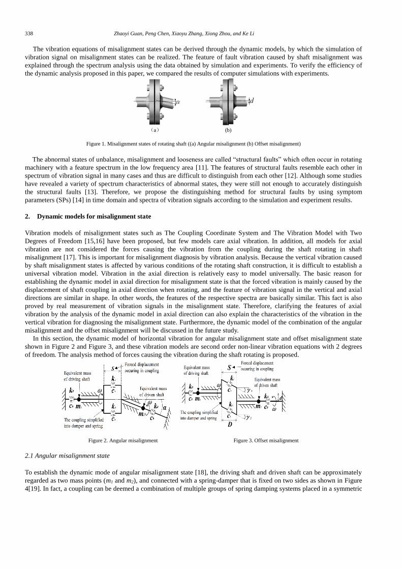
In this section, the dynamic model of horizontal vibration for angular misalignment state and offset misalignment state
shown in Figure 2 and Figure 3, and these vibration models are second order non-linear vibration equations with 2 degrees
of freedom. The analysis method of forces causing the vibration during the shaft rotating is proposed.
Figure 2. Angular misalignment Figure 3. Offset misalignment
2.1 Angular misalignment state
To establish the dynamic mode of angular misalignment state [18], the driving shaft and driven shaft can be approximately
regarded as two mass points (m1 and m2), and connected with a spring-damper that is fixed on two sides as shown in Figure
4[19]. In fact, a coupling can be deemed a combination of multiple groups of spring damping systems placed in a symmetric

Vibration Analysis of Shaft Misalignment and Diagnosis Method of Structure Faults for Rotating Machinery 339
manner, comprising one to four groups (and even more) of spring dampers. To better explain composition of this dynamic
model, a model with only one group of spring dampers is used here for description and dynamic analysis. The bolts of the
shaft coupling are also replaced by springs and dampers, and the dynamic model has two degrees of freedom within the
spring- damper-mass system. The nonlinear vibration equations of angular misalignment with tow-degree freedom are
established as formulas (1) and (2).
Figure 4. Dynamic model of angular misalignment
2
1 0 0 1 1 2 22
1 21 2
(x cos ) (x cos )
(x cos ) (x cos )0
m m
m m
d x dxm c k x k S x k S x
dt dt
d S x d S xc c
dt dt
(1)
2
2 0 0 1 1 2 22
1 21 2
cos ( cos x) cos ( cos x)
( cos x) ( cos x)cos cos 0
m mm m m
m m
d x dxm c k x k x S k x S
dt dt
d x S d x Sc c
dt dt
(2)
Here, m1 and m2 are the masses of the tow shaft, k0, k1, and k2 are spring constants, c0, c1, and c2 are damping coefficients,
x and xm are – respectively - the displacements of the driving shaft and driven shaft, and α is the misalignment angular
between the driving shaft and driven shaft. S1 and S2 are the respective displacements at the springs (k1, and k2) and dampers
(c1, and c2) of the shaft coupling. The forced vibration force of the angular misalignment state is caused by S1 and S2 while
the rotation of the shafts. The derivation method of S1 and S2 will be shown in the next chapter. In particular, due to great
varieties of material and shape, it is not easy to accurately determine spring coefficient and damping coefficient, which can
only be estimated through knocking experiment. However, this does not affect the most important spectral analysis
described below. This is because although these coefficients may affect amplitude of each frequency component in the
spectrum, the characteristic frequency upon shaft misalignment will not be affected and this frequency is the most critical
index for verification of effectiveness of this model. These vibration equations are used to analyze the axial vibration of the
angular misalignment state. The Runge-Kutta method is used to obtain the numerical solution of the equations [20].
2.2 Offset misalignment state
Similarly, the dynamic model of offset misalignment state is also established in the same manner as the angular
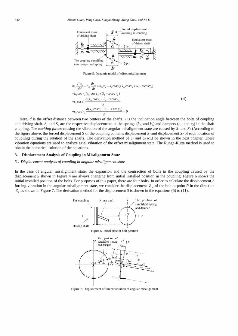
misalignment state, as shown in Figure 5. The bolts with an inclination angular of γ caused by offset misalignment in the
coupling are replaced by springs and dampers. The inclination angle γ in the coupling will produce the exciting force
causing vibration while rotating. The nonlinear vibration equations of offset misalignment with tow-degree freedom are
established as formulas (3) and (4).
2
1 01 01 1 1 1 1 12
2 2 2 2 2
1 1 1
1 1
2 2 2
2 2
cos (x cos cos )
cos (x cos cos )
(x cos cos )cos
(x cos cos )cos 0
m
m
m
m
d x dxm c k x k S x
dtdt
k S x
d S xc
dt
d S xc
dt
γ γ γ
γ γ γ
γ γγ
γ γγ
(3)
340 Zhaoyi Guan, Peng Chen, Xiaoyu Zhang, Xiong Zhou, and Ke Li
Figure 5. Dynamic model of offset misalignment
2
2 02 02 1 1 1 1 12
2 2 2 2 2
1 1 1
1 1
2 2 2
2 2
cos ( cos x cos )
cos ( cos x cos )
( cos x cos )cos
( cos x cos )cos 0
m m
m m
m
m
m
d x dxm c k x k x S
dtdt
k x S
d x Sc
dt
d x Sc
dt
γ γ γ
γ γ γ
γ γγ
γ γγ
(4)
Here, d is the offset distance between two centers of the shafts. γ is the inclination angle between the bolts of coupling
and driving shaft. S1 and S2 are the respective displacements at the springs (k1, and k2) and dampers (c1, and c2) in the shaft
coupling. The exciting forces causing the vibration of the angular misalignment state are caused by S1 and S2 (According to
the figure above, the forced displacement S of the coupling contains displacement S1 and displacement S2 of each location of
coupling) during the rotation of the shafts. The derivation method of S1 and S2 will be shown in the next chapter. These
vibration equations are used to analyze axial vibration of the offset misalignment state. The Runge-Kutta method is used to
obtain the numerical solution of the equations.
3. Displacement Analysis of Coupling in Misalignment State
3.1 Displacement analysis of coupling in angular misalignment state
In the case of angular misalignment state, the expansion and the contraction of bolts in the coupling caused by the
displacement S shown in Figure 4 are always changing from initial installed position in the coupling. Figure 6 shows the
initial installed position of the bolts. For purposes of this paper, there are four bolts. In order to calculate the displacement S
forcing vibration in the angular misalignment state, we consider the displacement PZ of the bolt at point P in the direction
1Z as shown in Figure 7. The derivation method for the displacement S is shown in the equations (5) to (11).
Figure 6. Initial state of bolt position
Figure 7. Displacement of forced vibration of angular misalignment

Vibration Analysis of Shaft Misalignment and Diagnosis Method of Structure Faults for Rotating Machinery 341
cosR r (5)
0 sinPZ r (6)
1 0 0 cos sin cosP PZ Z r (7)
1 sin( t )PZ r (8)
P 0 1P 1P0Z (Z Z )cos rsin
{rsin( t ) sin cos }cos
PZ
r
(9)
The displacement S of bolt is:
1P 1P0(Z Z )cos
{sin( t ) sin cos }sin
pS X
r
(10)
The differentiation dS of S is:
sin cos( t )dS
rdt
(11)
S and dS are necessary for the dynamic analysis of the misalignment state.
3.2 Displacement analysis of coupling in offset misalignment state
In the case of offset misalignment state, the displacements Sin bolts do not change with the installed positions in the
coupling. The bolts are replaced by springs as shown in Figure 8.
Setting the center of coupling A on driving shaft as the coordinate origin, the center of the coupling B on driven shaft,
and the coordinates of point P and Q can be calculated by the following formula.
Figure 8. Displacement of forced vibration of offset misalignment state
0
cos
sin
x
y
z
P
P P r t
P r t
(12)
cos
sin
x
y
z
Q D
Q Q r
Q r d
(13)
The distance R between points P and Q is as follows:
2 2 2
2 2 2 2
( ) ( ) ( )
(cos cos ) ( sin sin )
x x y y z zR P Q P Q P Q
r t D r t r d
(14)
Angle satisfy the following conditions:
sin t
tan tancos t
r d
r
(15)

342 Zhaoyi Guan, Peng Chen, Xiaoyu Zhang, Xiong Zhou, and Ke Li
When cos t 0 :
1 sin t
tancos t
r d
r
(16)
When cos t 0 :
1 sin t
tancos t
r d
r
(17)
When sin t 1 :
2
(18)
When sin t 1 :
2
(19)
When 0t :
1
0 tand
r
(20)
The distance 0R between points P and Q is as follow (21)
2 2
2 2
02 2 2 2
1r d
R r D r dr d r d
(21)
The displacement PQ
S in bolt is:
0PQS R R (22)
The cosine of displacement S in axis direction is:
PQS
S DR
(23)
Angle between bolt and X -axis is:
1cos ( )
D
R (24)
Here, S is equivalent to S1 and S2 in formula (3) and (4).
4. Simulation Result and Experiment Result
Numerical analysis of the computer simulation for misalignment state was performed by the dynamic model discussed

Vibration Analysis of Shaft Misalignment and Diagnosis Method of Structure Faults for Rotating Machinery 343
above and the Runge-Kutta method. When carrying out the computer simulation, the spring constant k of bolts needs to be
decided, and its value changes with tension or compression while the shaft rotates. That is to say, as shown in Figure 9,
when the bolt position in the coupling is in the tension state and the bolt is pulled, the spring constant equals the natural
spring constant of the bolt. When the bolt position in the coupling is in the compression state, because the bolt cannot be
compressed due to the bolt hole, the spring constant is equal to the spring constant of the rubber installed in the coupling. In
this paper, the change of the spring constant with coupling rotation is introduced to the dynamic models so that the
characteristics of the misalignment state for the computer simulation are more accurately reflected.
Figure 9. The spring constant in the bolts Figure 10. Rotation simulator and misalignment states
The experiment for verification was carried out using a rotating machine consisting of a rotating shaft, coupling, belt
drive, motor and other components as shown in Figure 10. Misalignment states can be set into angular and off-set
misalignments. Vibration acceleration signals of the misalignment states were measured by accelerometers. Figure 11 shows
the result comparison of spectra of acceleration between simulations and experiments. To obtain vibration signals under
each state, the accelerometer is placed on bearing seat to measure vibration signals in axial direction, transverse direction,
and vertical direction. Since this study needs to verify effectiveness of the axial vibration model, only axial vibration signals
are compared with simulation results. Each measurement lasted 20s and adopted sampling frequency of 5000Hz and
rotation speed of 600rpm, 1000rpm, and 1200rpm. Under the same state and rotation speed, vibration signals were measured
three times.
In Figure 11, the magnitude of spectrum is normalized by the following formula.
0 4
'( )( )
max { ( )}rf to f
F fF f
F f
(25)
Figure 11. Comparison of spectra between simulations and experiments
Here, fr is rotating frequency, and F’(f) is original spectrum calculated from time data by simulation and experiment.
Structure fault diagnosis of rotating machinery focuses on the shape of the spectrum but not the magnitude value. For this
reason in this study the spectrum is normalized by the formula (25).
344 Zhaoyi Guan, Peng Chen, Xiaoyu Zhang, Xiong Zhou, and Ke Li
Upon misalignment of rotating shaft, with rotation of the shaft, periodic abnormal vibration will be generated, with its
characteristic in the frequency spectrum normally occurring in the low frequency zone: apparent peaks are seen at frequency
of N/60 (N is shaft rotation speed) and its multiples. This is an important characteristic that can be used to differentiate
normal state and misalignment state. Also, based on different abnormity states, its frequency spectrum has different
characteristics.
From these results shown in Figure11, in the case of misalignment state, the spectrum F(fr) at the rotation frequency fr
and its harmonic components F(2fr), F(3fr) and F(4fr) are often appear both the results of simulations and experiments. The
feature that the peaks in the spectrum appeared at the rotation frequency and its harmonic components can be used to
distinguish normal state and other structure faults for rotating machinery. This verifies effectiveness of this dynamic
vibration model. However, due to the difficulty of identifying the coefficients of springs (k1, and k2) and dampers (c1, and c2)
in real machine precisely, the amplitudes at the rotation frequency and the harmonic frequencies obtained by the
experiments are not perfectly matched with the results of simulations. Based on characteristics of this frequency spectrum,
normal state and shaft misalignment state can be readily differentiated, and effectiveness of this dynamic vibration model
can be verified. Also, this proves that the spring coefficient and the damping coefficient only affect amplitude of the
characteristic frequency spectrum, not its position (frequency in Hz); that is to say, precision diagnosis of rotating shaft
structural faults is not significantly affected.
5. Method of Distinguishing Structure Faults of Rotating Machinery
Unbalance, misalignment and looseness are called “structural faults” which often occur in rotating machinery with a feature
spectrum in the low frequency area. Structural faults cause shafts to bear excessive fatigue and are the main reason of
subsequent failures in other parts, such as bearings and gears. That is to say, structural faults can cause the machinery
system to break down and may lead to serious human and economic losses. Therefore, detecting and distinguishing
structural faults are extremely important for guaranteeing production efficiency and plant safety. However, because the
features of structural faults resemble each other in the vibration signal spectrum in many cases, they are difficult to
distinguish. Therefore, we proposed the distinguishing method for structural faults using symptom parameters (SPs) in time
domain and spectra of vibration signals according to the simulation and experimental results [21]. (Based on frequency
spectrum features demonstrated by misalignment dynamic vibration model and experiment proposed earlier, we hereby
propose a diagnosis method combining time domain characteristic parameters with frequency spectral analysis for diagnosis
of rotating shaft structural faults).
5.1 Signal measurement in each state using rotating simulator
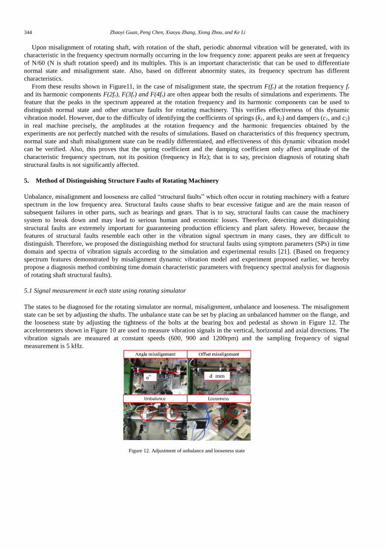
The states to be diagnosed for the rotating simulator are normal, misalignment, unbalance and looseness. The misalignment
state can be set by adjusting the shafts. The unbalance state can be set by placing an unbalanced hammer on the flange, and
the looseness state by adjusting the tightness of the bolts at the bearing box and pedestal as shown in Figure 12. The
accelerometers shown in Figure 10 are used to measure vibration signals in the vertical, horizontal and axial directions. The
vibration signals are measured at constant speeds (600, 900 and 1200rpm) and the sampling frequency of signal
measurement is 5 kHz.
Figure 12. Adjustment of unbalance and looseness state
Vibration Analysis of Shaft Misalignment and Diagnosis Method of Structure Faults for Rotating Machinery 345
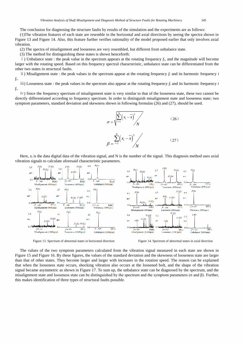
The conclusion for diagnosing the structure faults by results of the simulation and the experiments are as follows:
(1)The vibration features of each state are resemble in the horizontal and axial directions by seeing the spectra shown in
Figure 13 and Figure 14. Also, this feature further verifies rationality of the model proposed earlier that only involves axial
vibration.
(2) The spectra of misalignment and looseness are very resembled, but different from unbalance state.
(3) The method for distinguishing these states is shown henceforth:
ⅰ) Unbalance state : the peak value in the spectrum appears at the rotating frequency fr, and the magnitude will become
larger with the rotating speed. Based on this frequency spectral characteristic, unbalance state can be differentiated from the
other two states in structural faults.
ⅱ) Misalignment state : the peak values in the spectrum appear at the rotating frequency fr and its harmonic frequency i
fr.
ⅲ) Looseness state : the peak values in the spectrum also appear at the rotating frequency fr and its harmonic frequency i
fr.
ⅳ) Since the frequency spectrum of misalignment state is very similar to that of the looseness state, these two cannot be
directly differentiated according to frequency spectrum. In order to distinguish misalignment state and looseness state; two
symptom parameters, standard deviation and skewness shown in following formulas (26) and (27), should be used.
2
1
N
i
i
x x
N
(26)
3
1
N
i
i
x x
N
(27)
Here, xi is the data digital data of the vibration signal, and N is the number of the signal. This diagnosis method uses axial
vibration signals to calculate aforesaid characteristic parameters.
Figure 13. Spectrum of abnormal states in horizontal direction Figure 14. Spectrum of abnormal states in axial direction
The values of the two symptom parameters calculated from the vibration signal measured in each state are shown in
Figure 15 and Figure 16. By these figures, the values of the standard deviation and the skewness of looseness state are larger
than that of other states. They become larger and larger with increases in the rotation speed. The reason can be explained
that when the looseness state occurs, shocking vibration also occurs at the loosened bolt, and the shape of the vibration
signal became asymmetric as shown in Figure 17. To sum up, the unbalance state can be diagnosed by the spectrum, and the
misalignment state and looseness state can be distinguished by the spectrum and the symptom parameters (σ and β). Further,
this makes identification of three types of structural faults possible.

346 Zhaoyi Guan, Peng Chen, Xiaoyu Zhang, Xiong Zhou, and Ke Li
Figure 15. Standard deviation of different states and speeds Figure 16. Skewness of different states and speeds
Figure 17. Time signals of abnormal states
6. Conclusions
In this research, the dynamic models of axial vibration of shaft misalignment state were proposed. In order to obtain the
solution of the dynamic models and clarify the feature of the vibration signal in misalignment states, the method for
calculating the vibration displacement caused by each misalignment state was showed. The computer simulation and
experiment using rotating machine were also shown to verify the efficiency of the dynamic analysis method proposed in this
paper. The features of the vibration signal of misalignment states can be clarified and the mechanism of occurrence of
misalignment states can be explained theoretically based on the dynamic models.
Finally, the method for distinguishing structure faults of rotating machinery (shaft misalignment state, unbalance state
and looseness state) was discussed by using symptom parameters and spectrum of the vibration signal measured in these
states. The method is proved to be effective to distinguish structure faults of rotating machinery.
We will continue studying the dynamic analysis concerning the looseness state theoretically, and report the results in
subsequent studies (including the diagnosis method that uses new characteristic parameters).
References
1. Lei, Yaguo, et al, “A review on empirical mode decomposition in fault diagnosis of rotating machinery,” Mechanical Systems
and Signal Processing, Vol.35, No.1, pp.108-126, 2013.
2. Li, Zhinong, et al, “Hidden Markov model-based fault diagnostics method in speed-up and speed-down process for rotating
machinery,” Mechanical Systems and Signal Processing, Vol19, No.2, pp.329-339, 2005.
3. Li, Bo, et al, “Neural-network-based motor rolling bearing fault diagnosis,” IEEE Transactions on Industrial Electronics,
Vol.47, No.5, pp.1060-1069, 2000.
4. Randall, Robert B, “State of the art in monitoring rotating machinery-part 1,” Sound and vibration, Vol.38, No.3, pp.14-21,
2004.
5. Jalan, Arun Kr, and A. R. Mohanty, “Model based fault diagnosis of a rotor–bearing system for misalignment and unbalance
under steady-state condition,” Journal of Sound and Vibration, Vo.327, No.3, pp.604-622, 2009.
6. Patel, Tejas H., and Ashish K. Darpe, “Experimental investigations on vibration response of misaligned rotors,” Mechanical
Systems and Signal Processing, Vol.23, No.7, pp.2236-2252, 2009.
7. Omitaomu, Olufemi A., et al, “On-Line Prediction of Motor Shaft Misalignment Using Fast Fourier Transform Generated
Spectra Data and Support Vector Regression,” Journal of Manufacturing Science and Engineering, Vol.128, No.4, pp.1019-
1024, 2006.
8. Zhang J, Ma W, Lin J, et al, “Fault diagnosis approach for rotating machinery based on dynamic model and computational
intelligence,” Measurement, Vol.59, pp.73-87, 2015.
9. He, Guolin, et al, “A novel order tracking method for wind turbine planetary gearbox vibration analysis based on discrete

Vibration Analysis of Shaft Misalignment and Diagnosis Method of Structure Faults for Rotating Machinery 347
spectrum correction technique,” Renewable Energy, Vol.87, pp.364-375, 2016.
10. Kusiak, Andrew, and Anoop Verma, “Analyzing bearing faults in wind turbines: A data-mining approach,” Renewable Energy,
Vol.48, pp.110-116, 2012.
11. Jalan A K, Mohanty A R, “Model based fault diagnosis in rotating machinery [J],” International Journal of Performability
Engineering, 7(6): 515-523, 2011.
12. Hili M A, Fakhfakh T, Haddar M, “Failure analysis of a misaligned and unbalanced flexible rotor,” Journal of Failure Analysis
and Prevention, Vol.6(4), pp.73-82, 2006.
13. Betta, Giovanni, et al, “A DSP-based FFT-analyzer for the fault diagnosis of rotating machine based on vibration analysis,”
Instrumentation and Measurement Technology Conference, Vol.51, No.6, 2001, pp.1316-1322, 2002.
14. Chen P, Toyota T, He Z, “Automated function generation of symptom parameters and application to fault diagnosis of
machinery under variable operating conditions,” IEEE Transactions on Systems, Man, and Cybernetics-Part A: Systems and
Humans, Vol.31(6), pp.775-781, 2001.
15. Zigang, L., Jun, J., & Zhui, T. (2016), “Non-linear vibration of an angular-misaligned rotor system with uncertain parameters.”
Journal of Vibration and Control, 22(1), 129-144.
16. Hili, Molka Attia, et al, “Shaft misalignment effect on bearings dynamical behavior,” The International Journal of Advanced
Manufacturing Technology, Vol.26, No.5, pp.615-622, 2005.
17. Lee Y S, Lee C W, “Modelling and vibration analysis of misaligned rotor-ball bearing systems [J],” Journal of Sound and
Vibration, 224(1): 17-32, 1999.
18. Hussain V M S, Naikan V N A, “Reliability Modeling of Rotary Systems Subjected to Imbalance [J],” International Journal of
Performability Engineering, 9(4): 423-432, 2013.
19. Jalan A K, Mohanty A R, “Model Based Fault Identification of Unbalance and Misalignment Simultaneously Present in a Rotor
System [J],” Advances in Vibration Engineering, 12(1): 23-32, 2013.
20. Butcher, John Charles, “The Numerical Analysis of Ordinary Differential Equations: Runge–Kutta and General Linear Methods
(J. C. Butcher),” Wiley-Interscience, 1987.
21. Frank P M, “Fault diagnosis in dynamic systems using analytical and knowledge-based redundancy: A survey and some new
results,” Automatica, Vol.26(3), pp.459-474, 1990.