Embed Size (px)
Citation preview

Vibration Analysis of Cantilever Smart Structure
by using Piezoelectric Smart Material
K. B. Waghulde, Dr. Bimlesh Kumar
Mechanical Engineering Department
J. T. Mahajan College of Engineering, Faizpur,
(Maharashtra State) India, 425503
Emails: [email protected]
Submitted: June 21, 2011 Accepted: August 12, 2011 Published: September 1, 2011
Abstract- The field of smart structures and smart materials has been an emerging area of research for
last few decades. A smart structure would be able to sense the vibration and generate a controlled
actuation to it, so the vibration can be minimized. For this purpose, smart materials are used as
actuators and sensors. In this paper, some literature review is given about smart structure and smart
material. Piezoelectric material is used as smart material and cantilever beam is considered as a smart
structure. Different positions are considered for the model analysis. In this case, the modal analysis are
found out by using ANSYS and MATLAB.
Index terms: Smart structure, Smart materials, vibration analysis, vibration control, cantilever beam,
cantilever plate.
INTERNATIONAL JOURNAL ON SMART SENSING AND INTELLIGENT SYSTEMS, VOL. 4, NO. 3, SEPTEMBER 2011
353
I. INTRODUCTION
Smart structures is a rapidly advancing field with the range of support and enabling technologies
having significant advances, notable optics and electronics. The definition of smart structure was
a topic of controversy from the late 1970 to 1980. In order to define this a special workshop was
organized by the US army research office in 1988 in which Sensors, Actuators, Control
mechanism and Timely response were recognized as the four qualifying features of any smart
system or structures.
In this workshop Smart structure is defined as “A system or material which has built in intrinsic
Sensor, actuator and control mechanism whereby it is capable of sensing a stimulus, responding
to it in a predetermined manner and extent, in a short time and reverting to its original state as
soon as the stimulus is removed.”
According to Spilman a smart structure is defined as “a physical structure having a definite
purpose, means of imperactive to achieve that purpose and the pattern of functioning of a
computer.”
Smart structure contains a host structure, a sensor to gauge its internal state, an actuator to affect
its internal state and, a controller whose purpose is to process the sensors and appropriately send
signals to actuators.
Vibration control is an important area of interest in several industrial applications. Unwanted
vibration can have a detrimental and sometimes catastrophic effect on the serviceability or
structural integrity of mechanical systems. To control the vibrations in a system, different
techniques have been developed. Some of these techniques and methods use piezoelectric
materials as sensors or actuators.
A vibration isolation system is called active if it uses external power to perform its function. It
consists a servomechanism with a sensor, actuator, signal processor. Active control systems are
required in applications where passive vibration control is not possible because of material
constraints or simply not sufficient for the level of control required. Active control is a favorable
method of control because it works in a wide frequency range, reducing resonant vibrations
within that range and because it is adaptive to changes in the nature of the disturbance. The
relationship between these structure types is clearly explained in the following fig.
K. B. Waghulde, and Bimlesh Kumar, Vibration Analysis of Cantilever Smart Structure by using Piezoelectric Smart Material
354

Figure 1. Classification of smart structures
(A) Sensory Structures: These structures possess sensors that enable the determination or
monitoring of system states/ characteristics.
(B) Adaptive Structures: These structures possess actuators that enable the alteration of system
states or characteristics in a controlled manner.
(C) Controlled Structures: These result from the intersection of the sensory and the adaptive
structures. These possess both sensors and actuators integrated in feedback architecture for
the purpose of controlling the system states or characteristics.
(D) Active Structures: These structures possess both sensors and actuators that are highly
integrated into the structure and exhibit structural functionality in addition to control
functionality.
(E) Intelligent Structures: These structures are basically active structures possessing highly
integrated control logic and electronics that provides the cognitive element of a distributed or
hierarchic control architecture
II. ACTIVE SMART MATERIALS
Active smart materials are those materials which possess the capacity to modify their geometric
or material properties under the application of electric, thermal or magnetic field, thereby
acquiring an inherent capacity to transducer energy. The active smart materials are Piezoelectric
material, Shape memory alloys, Electro-rheological fluids and Magneto-structive materials.
Being active they can be used as force transducers and actuators. The materials which are not
active under the application of electric, thermal or magnetic field are called Passive smart
INTERNATIONAL JOURNAL ON SMART SENSING AND INTELLIGENT SYSTEMS, VOL. 4, NO. 3, SEPTEMBER 2011
355

materials. Fiber optic material is good example of passive smart material. Such materials can act
as sensors but not as actuators and transducers.
a) SHAPE MEMORY ALLOY’S (SMA)
A shape memory alloy (SMA) is able to memories and recover its original shapes after deformed
by heating over its transformation temperature. During this transformation large forces or large
deformation are generated which can be used for actuation. There are main two types of alloy
exhibit a strong shape memory effect copper alloys (Cu-Zn-Al and Cu-Al-Ni) and Nitinols (Ni-
Ti) (Nickel – Titanium Alloy)
The main drawbacks of SMA based actuators are comparatively slow response time. This
problem is inherent since these alloys rely on heating and cooling for their actuation. Therefore
SMA’s are not suitable for high frequency control.
SMA made eyeglass frame, Antenna of mobile phone, SMA wire are used as passive energy
dissipater to increase the hysteresis damping in structure under earthquake. In advanced
application in robotics artificial arms, for buckling control, in medical instruments such as
vascular stents and filters.
b) Electro/Magneto-Rheological Fluid: (ER / MR Fluids)
ER and MR fluids materials that respond to an applied electric or magnetic field respectively with
a important change in Rheological behavior. This is more a semi-smart behavior in the sense that
the application of a third party field (Electric or Magnetic) will act on a classical coupling
(Viscosity) and that there is no reciprocal effect. These fluids are non-colloidal suspension of
polarisable small particles. Their essential characteristic is their ability to reversibly change from
a free-flowing, linear viscous liquid to a semi solid with controllable yield strength in
Shape Memory Alloy Heat Original Memorised Shape
ER / MR Fluids Electric/Magnetic Field
Change in Viscosity
K. B. Waghulde, and Bimlesh Kumar, Vibration Analysis of Cantilever Smart Structure by using Piezoelectric Smart Material
356

milliseconds when exposed to a electric or magnetic field. In absence of an applied field,
controllable fluids are reasonably well approximated as Newtonian liquids.
These fluids provides simple, quiet, rapid-response interfaces between electronic controls and
mechanical systems. These fluids are used as fast acting, fluid valves with no moving parts in
semi-active vibration control system. It is noted that the maximum shear stress obtainable using
MR fluids is about 20 times bigger than the maximum shear stress obtainable using ER fluids.
c) Magneto-strictive materials
Magnetostriction is the process by which a ferromagnetic material transforms from one shape to
another in the presence of magnetic field. Most ferromagnetic materials exhibit some measurable
magnetostriction. Conversely if an external force produce a strain in magneto-strictive material,
the materials magnetic state is change. Due to bi-directional effect magneto-strictive materials is
used for both actuation and sensing devices. Magneto-strictive materials operates when a
compressive load is applied to the material, due to the magneto-elastic coupling forces the
domain structure to orient perpendicular to the applied force. Then as a magnetic field is
introduced, the domain structure rotates producing the maximum possible strain in the material.
Terfenol-D8 (Alloy of the form Tbx Dyl – Xfe2) exhibits the greatest magnetostrictive effect.
The magnetostrictive properties of Terfenol D-8 depends on the magnetic and mechanical bias
conditions. As compressive load is increased, larger values of field bias as well as larger drive
field are required. The coupling factor decreases with increasing magnetic and mechanical bias.
d) Piezoelectric material
Piezoelectricity is the ability of a material to develop an electric charge when subjected to a
mechanical strain, this effect is called Direct Piezoelectric Effect (DPE) and Conversely material
develop mechanical strain in response to an applied electric field, this effect is called Converse
Magneto-strictive materials Magnetic Field Mechanical Strain
Piezoelectric Material
1. Stress 2. Electric Charge
1. Electric Charge 2. Stress
INTERNATIONAL JOURNAL ON SMART SENSING AND INTELLIGENT SYSTEMS, VOL. 4, NO. 3, SEPTEMBER 2011
357

Piezoelectric Effect (CPE). Due to this coupled mechanical and electrical properties, piezoelectric
materials make them well suited for use as sensors and actuators. Sensors use Direct Piezoelectric
Effect (DPE) and actuators use Converse Piezoelectric Effect (CPE). As a sensors, deformations
cause by the dynamic host structure produce an electric change resulting in an electric current in
the sensing circuit. While as an actuators, a high voltage signal is applied to piezoelectric device
which deforms the actuator and transmit mechanical energy to the the host structure.
Piezoelectric materials basically divided into two group Piezo-ceramics and piezo-polymers.
Piezo-ceramics: The most common commercial piezo-polymer is Barium Titanate (BaTiO3),
Lead Titanate (PbTiO3), Lead Zirconate ((PbZrO3) Lead metaniobate (PbNb2O6) and Lead
(plumbum) Zirconate Titanate (PZT) [Pb(ZrTi)O3]. Among these materials last Lead (plumbum)
Zirconate Titanate (PZT) become the dominant piezo-electric ceramic material for transducer due
to its high coupling coefficient (0.65). When this PZT plate subjected to static or dynamic loads,
it can generate voltages as high as 20,000 volts.
Examples: Microphones, headphones, loudspeakers, buzzers, wrist watches, clocks, calculators,
hydrophones and projectors.
Piezo-polymers: The most common commercial piezo-polymer is polyvinvylidene Fluoride
(PVDF). It is made up of long chains of the repeating monomer (- Ch2 – Cf2 -) each of which has
an inherent dipole moment. Both PZT and PVDF are usually produced in the thin sheets with
film of metal deposited on the opposite surface to form electrodes. Piezo-polymers are tough and
flexible they have small stiffness due to this PVDF are good candidates for sensing of their small
stiffness while Piezo-ceramics are brittle and stiff and having greater elastic modulus for effective
mechanical coupling to the structure hence it is better suited for actuators. Hence PVDF used as
Sensors and PZT used as Actuators.
Pizoelectric materials are works in both way (DPE and CPE) and also applicable for low as well
as high frequency response. These materials are following Features/Advantages/Properties of
PZT materials over remaining three materials.
1) The materials has resilience property, light in weight and high bandwidth of devices.
2) Unlimited resolution: PZT actuators makes motion in the sub-nanometer range. Hence they
have no moving parts in contact with each other to limit resolution.
K. B. Waghulde, and Bimlesh Kumar, Vibration Analysis of Cantilever Smart Structure by using Piezoelectric Smart Material
358
3) No wear and tear: PZT materials has no moving parts like gears, bearings hence no wear and
tear are shows.
4) Fast expansion: This material react in a matter of microseconds. Acceleration rates of this
material are more than 10,000 x g.
5) High force generation: The PZT materials are capable for the moving loads of several tones. In
this case large masses can be moved and positioned accurately.
6) No magnetic field: PZT material do not produce magnetic field nor affected by the magnetic
field hence suited for application where magnetic field cannot be tolerated.
7) Low power consumption: This materials are holding heavy loads for long periods consumes
virtually no power/very less power.
8) Operation at cryogenic temperature: The PZT materials are effected continuously even at
temperature close to 0 Kelvin.
By applying properties of PZT materials some researchers utilized the PZT materials in precision
control of dynamical systems due to their special characteristics. Some are used the PZT
materials as elements of an intelligent structure. They introduce an analytical model and
compared it with an experimental set. They performed a scaling analysis to demonstrate that the
effectiveness of PZT actuators are independent of the size of the structure and to evaluate various
PZT materials base on their effectiveness in transmitting strain to the substructure. Many
researchers are used a PZT actuator in a fixed position, the first two modes of vibration for a
beam were controlled. They used single actuator to suppress vibrations by using acceleration
feedback controllers. Knowing the frequencies for a smart structure helps in designing the
parameters of controller. Some are explained that the PZT ceramics are used for reconstruction
filters.
III. VIBRATION ANALYSIS OF CANTILEVER BEAM
In this paper, a simple smart system with a PZT sensor and a PZT actuator is tested for vibration
Analysis. The length, width and depth of the beam are taken as 0.08, 0.001 and 0.016 m,
respectively. For the PZT sensor and actuator, the length, width and depth are taken as 0.01,
0.0004 and 0.016 m, respectively. The material properties are listed in Table 1.
INTERNATIONAL JOURNAL ON SMART SENSING AND INTELLIGENT SYSTEMS, VOL. 4, NO. 3, SEPTEMBER 2011
359

Table 1:- Material Properties for Piezoceramic and Steel plate
Piezoceramic (BM500) Values
Elasticity matrix at constant electric field, c11 (Pa) 1.26 × 10¹¹
Elasticity matrix at constant electric field, c12 (Pa) 8.41 × 10¹¹
Elasticity matrix at constant electric field, c22 (Pa) 1.17 × 10¹¹
Elasticity matrix at constant electric field, c33 (Pa) 1.26 × 10¹¹
Piezoelectric constant matrix, e21 (C/m2) -5.4
Piezoelectric constant matrix, e22 (C/m2) 15.8
Dielectric matrix at constant strain, ε 11(F/m) 1.151 × 10⁻³
Dielectric matrix at constant strain, ε 22 (F/m) 1.043 × 10⁻³
Mass density, ρ (kg/m2) 7800
Beam (Steel)
Young modulus, Y (Pa) 2.07 × 10¹¹
Poission’s ratio, γ 0.3
Mass density , ρ (kg/m3) 7800
The model of cantilever beam will be done using commercial FE software (ANSYS). In ANSYS,
the beam is modeled with a 2-D elastic beam element (BEAM3), and the PZT actuator and sensor
are modeled using a 2-D coupled field element (PLANE13).
Figure 2. Finite Element Mesh of the Beam and PZT’s System
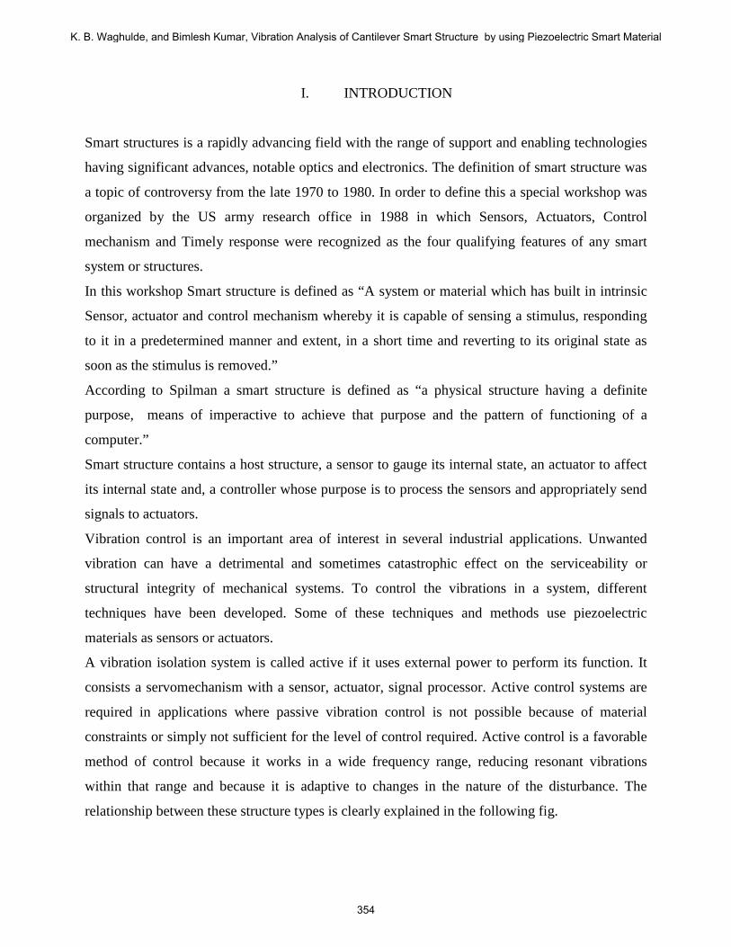
Before we start the analysis in ANSYS, we have to check that our actuator locations do not
interface with the modal nodes. That is, the actuator node where we feed the input voltages
should not be on the same location of the modal nodes, i.e. transverse displacement should not be
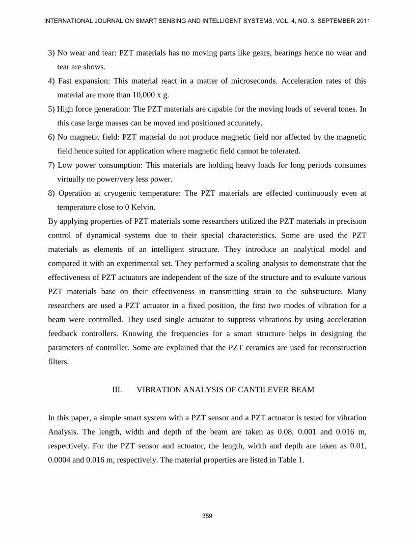
zero. Figures 3 to 5 show the first three mode shapes for the beam with and without the PZT
actuator.
K. B. Waghulde, and Bimlesh Kumar, Vibration Analysis of Cantilever Smart Structure by using Piezoelectric Smart Material
360
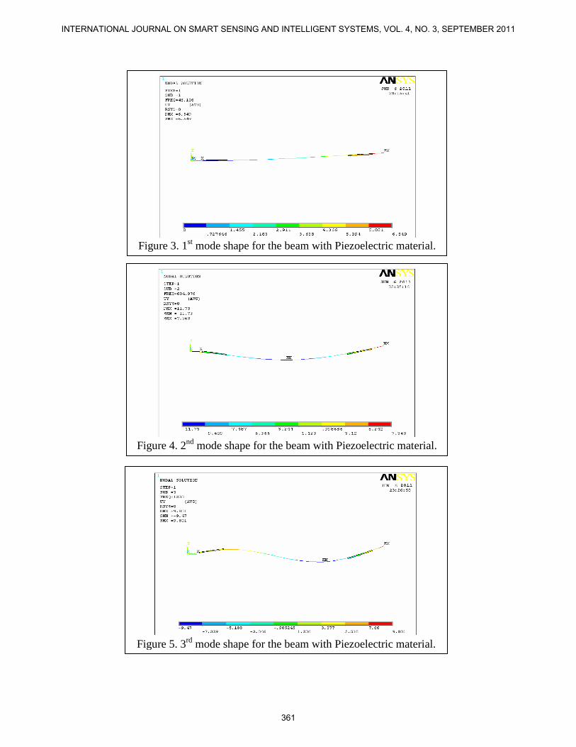
Figure 3. 1st mode shape for the beam with Piezoelectric material.
Figure 4. 2nd mode shape for the beam with Piezoelectric material.
Figure 5. 3rd mode shape for the beam with Piezoelectric material.
INTERNATIONAL JOURNAL ON SMART SENSING AND INTELLIGENT SYSTEMS, VOL. 4, NO. 3, SEPTEMBER 2011
361

Table-2 shows the values for the natural frequencies and transverse displacement at node 5 for
the first three mode shapes at each PZT actuator location.
TABLE 2:-Transverse displacements for node 5 of the actuator for
the first three mode shapes of the beam with PZT's. Location (mm) Mode-shape Frequency (Hz) Displacement (mm)
5 1st mode 40.016 0.32141
5 2nd mode 604.97 -4.9201
5 3rd mode 1233 5.5120
15 1st mode 44.336 0.95776
15 2nd mode 385.52 -6.0748
15 3rd mode 1197 1.3826
20 1st mode 132.41 3.7923
20 2nd mode 411.98 -4.3288
20 3rd mode 1394 -3.1248
25 1st mode 42.301 1.7350
25 2nd mode 304.15 -5.5271
25 3rd mode 1362 -1.4421
35 1st mode 39.748 2.5323
35 2nd mode 292.52 -4.6329
35 3rd mode 1545 -3.8977
40 1st mode 81.230 5.5361
40 2nd mode 534.62 0.02037
40 3rd mode 1165.8 -2.4540
45 1st mode 36.742 3.2465
45 2nd mode 338.40 -3.2314
45 3rd mode 1663 -4.6054
60 1st mode 51.094 5.9164
60 2nd mode 638.85 3.7533
60 3rd mode 1270.7 4.3589
K. B. Waghulde, and Bimlesh Kumar, Vibration Analysis of Cantilever Smart Structure by using Piezoelectric Smart Material
362

Table-3 shows the values for the first three natural frequencies obtained from ANSYS and
MATLAB for the cantilever beam with piezoelectric actuators and sensors. From this point we
can start the study with the model we did in ANSYS.
TABLE 3:-First three natural frequencies
Mode
shape
Natural frequency with
Pizoelectric Material
MATLAB ANSYS
1st mode 63.45 63.53
2nd mode 410.45 410.96
3rd mode 1153.11 1153.3
From table 2, in all the cases, node 5 has values for the transverse displacement other than zero.
So we can conclude from the table that the actuator can be placed in all those locations.
IV. VIBRATION ANALYSIS OF CANTILEVER PLATE
In this case, a smart system consisting of a plate fixed at one side and mounted with a PZT sensor
and a PZT actuator is tested for vibration control. The length, width and thickness of the plate are
0.1, 0.03 and 0.002 m, respectively. For the PZT sensor and actuator, the length, width and
thickness are taken as 0.02, 0.01 and 0.002 m, respectively. Figure 6 shows the plate with PZT
actuator and sensor. The material properties are listed in Table 4.1.
Figure 6. Smart structure consisting of steel plate, PZT sensor and PZT actuator
INTERNATIONAL JOURNAL ON SMART SENSING AND INTELLIGENT SYSTEMS, VOL. 4, NO. 3, SEPTEMBER 2011
363

Table 4: Material Properties for the plate with PZT's
Piezoceramic (BM500) Standard Values
C11 (Pa) 1.26 X 10¹¹
C12 (Pa) 8.41 X 10¹⁰
C13 (Pa) 7.95 X 10¹⁰
C22 (Pa) 1.17 X 10¹¹
C23 (Pa) 8.41 X 10¹⁰
C33 (Pa) 1.26 X 10¹¹
C44 (Pa) 2.30 X 10¹⁰
C55 (Pa) 2.30 X 10¹⁰
C66 (Pa) 2.35 X 10¹⁰
e12 (C/m2) -5.4
e22 (C/m2) 15.8
e32 (C/m2) -5.4
e41 (C/m2) 12.3
e53 (C/m2) 12.3
ε11 (F/m) 1.151 X 10⁻³
ε 22 (F/m) 1.043 X 10⁻³
ε 33 (F/m) 1.151 X 10⁻³
ρ (Kg/m3) 7800
Beam(Steel)
Y (Pa) 2.07 X 10¹¹
υ 0.3
ρ (Kg/m3) 7800
Since we have five mechanical DOF for each node of the plate, the total mechanical DOF of the
plate will be 236 (the nodes at the fixed side have zero DOF). Having the PZT's grounded at the
boundary with the plate gives a total of 12 electrical DOF. In ANSYS, the plate is modeled using
an elastic 4-noded element (SHELL63) and the PZT's are modeled using a 3-D coupled element
(SOLID5). The actuator are placed in six different positions as shown in Figure 7. Note that each
square is 0.01 x 0.01 m in size.
K. B. Waghulde, and Bimlesh Kumar, Vibration Analysis of Cantilever Smart Structure by using Piezoelectric Smart Material
364
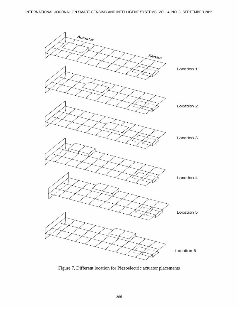
Figure 7. Different location for Piezoelectric actuator placements
INTERNATIONAL JOURNAL ON SMART SENSING AND INTELLIGENT SYSTEMS, VOL. 4, NO. 3, SEPTEMBER 2011
365

Table 5: Transverse displacements for nodes 3 and 6 of the actuator for the first seven mode shapes of the beam with PZT's. (Location 1)
Mode Shape Natural
Frequency (Hz)
Node Displacement
1st mode 159.05 3 1.1435
1st mode 159.05 6 1.1435
2nd mode 999.072 3 -4.6965
2nd mode 999.072 6 -4.6965
3rd mode 1181.00 3 -1.3187
3rd mode 1181.00 6 -1.3187
4th mode 2135.00 3 0.0039
4th mode 2135.00 6 -0.0039
5th mode 2808.00 3 6.4518
5th mode 2808.00 6 6.4518
Table 6: Transverse displacements for nodes 3 and 6 of the actuator for the first seven mode shapes of the beam with PZT's. (Location 2)
Mode Shape Natural
Frequency (Hz)
Node Displacement
1st mode 154.22 3 2.8706
1st mode 154.22 6 2.8706
2nd mode 983.45 3 6.1449
2nd mode 983.45 6 -6.1449
3rd mode 1175.6 3 -2.4985
3rd mode 1175.6 6 2.4985
4th mode 2118.6 3 0.0756
4th mode 2118.6 6 0.0756
5th mode 2848.9 3 0.0693
5th mode 2848.9 6 0.0693
K. B. Waghulde, and Bimlesh Kumar, Vibration Analysis of Cantilever Smart Structure by using Piezoelectric Smart Material
366

Table 7: Transverse displacements for nodes 3 and 6 of the actuator for the first seven mode shapes of the beam with PZT's. (Location 3)
Mode Shape Natural
Frequency (Hz)
Node Displacement
1st mode 149.37 3 4.8474
1st mode 149.37 6 4.8774
2nd mode 1006.5 3 2.9008
2nd mode 1006.5 6 2.9008
3rd mode 1153.3 3 -3.3363
3rd mode 1153.3 6 3.3363
4th mode 2079.6 3 0.0437
4th mode 2079.6 6 -0.0437
5th mode 2881.3 3 5.5822
5th mode 2881.3 6 5.5822
Table 8: Transverse displacements for nodes 3 and 6 of the actuator for the first seven mode shapes of the beam with PZT's. (Location 4)
Mode Shape Natural
Frequency (Hz)
Node Displacement
1st mode 158.55 3 1.1457
1st mode 158.55 6 1.1105
2nd mode 993.06 3 -4.7379
2nd mode 993.06 6 -4.9304
3rd mode 1172.8 3 1.2876
3rd mode 1172.8 6 3.8390
4th mode 2162.3 3 0.2828
4th mode 2162.3 6 0.3559
5th mode 2795.9 3 6.65
5th mode 2795.9 6 7.6441
INTERNATIONAL JOURNAL ON SMART SENSING AND INTELLIGENT SYSTEMS, VOL. 4, NO. 3, SEPTEMBER 2011
367

Table 9: Transverse displacements for nodes 3 and 6 of the actuator for the first seven mode shapes of the beam with PZT's. (Location 5)
Mode Shape Natural
Frequency (Hz)
Node Displacement
1st mode 153.88 3 2.8688
1st mode 153.88 6 2.8449
2nd mode 975.00 3 -6.3801
2nd mode 975.00 6 -7.4088
3rd mode 1150.4 3 1.0753
3rd mode 1150.4 6 5.7993
4th mode 2127.4 3 -0.1163
4th mode 2127.4 6 -0.2133
5th mode 2838.4 3 0.1304
5th mode 2838.4 6 0.5438
Table 10: Transverse displacements for nodes 3 and 6 of the actuator for the first seven mode shapes of the beam with PZT's. (Location 6)
Mode Shape Natural
Frequency (Hz)
Node Displacement
1st mode 149.29 3 4.8801
1st mode 149.29 6 4.8737
2nd mode 987.46 3 -3.5840
2nd mode 987.46 6 -5.8057
3rd mode 1112.6 3 1.6176
3rd mode 1112.6 6 7.5023
4th mode 2078.6 3 0.0181
4th mode 2078.6 6 -0.0562
5th mode 2876.9 3 -5.3690
5th mode 2876.9 6 -5.6585
K. B. Waghulde, and Bimlesh Kumar, Vibration Analysis of Cantilever Smart Structure by using Piezoelectric Smart Material
368

Figure 8. 1st
mode shape for the plate with PZT's (PZT actuator placed at location 1).
Figure 9. 2nd
mode shape for the plate with PZT's (PZT actuator placed at location 1).
INTERNATIONAL JOURNAL ON SMART SENSING AND INTELLIGENT SYSTEMS, VOL. 4, NO. 3, SEPTEMBER 2011
369

Figure 10. 3rd
mode shape for the plate with PZT's (PZT actuator placed at location 1).
Figure 11. 4th
mode shape for the plate with PZT's (PZT actuator placed at location 1).
K. B. Waghulde, and Bimlesh Kumar, Vibration Analysis of Cantilever Smart Structure by using Piezoelectric Smart Material
370

Figure 12. 5th
mode shape for the plate with PZT's (PZT actuator placed at location 1).
Figure 13. 6th
mode shape for the plate with PZT's (PZT actuator placed at location 1).
INTERNATIONAL JOURNAL ON SMART SENSING AND INTELLIGENT SYSTEMS, VOL. 4, NO. 3, SEPTEMBER 2011
371

Figure 14. 7th
mode shape for the plate with PZT's (PZT actuator placed at location 1).
Tables 5 – 10 shows the values for the transverse displacements for the actuator nodes 3 and 6 at
each location for the first seven natural frequencies. Figures 8 – 14 show the first seven mode
shapes for the plate with the PZT's for the first actuator location, that is location 1.
Figure 15. Natural frequencies for different locations of Piezoelectric Actuator.
K. B. Waghulde, and Bimlesh Kumar, Vibration Analysis of Cantilever Smart Structure by using Piezoelectric Smart Material
372

Figure 16. Displacements for different location of Piezoelectric Actuator
Figure 15 and 16 shows that the natural frequencies and displacements for different locations of
piezoelectric actuator. The natural frequencies are slightly change for different locations but the
displacements changes are in large magnitudes. This shows that if the position of piezoelectric
actuator are change then the vibration parameters are also changes.
V. CONCLUSIONS
In this a comprehensive study of smart materials and smart structures is done. For the effect of
the piezoelectric actuator placement on controlling the structural vibrations. Two systems were
used for this study, the first one was a 2-D beam with PZT actuator and sensor, and the second
one was a 3-D plate with PZT actuator and sensor. Both systems were modeled in ANSYS. All
the cases, for both systems, showed that our actuator locations used for the study were acceptable
since the feeding node had transverse displacement values that were not zero. For the 2-D beam,
the modal nodes were checked up to the 3rd
mode shape, whereas for the 3-D plate we checked up
to the 5th
mode shape.
INTERNATIONAL JOURNAL ON SMART SENSING AND INTELLIGENT SYSTEMS, VOL. 4, NO. 3, SEPTEMBER 2011
373

REFERENCES
[1] Henrique Santos, Cristovao, M. Mota Soares, Carlos A. Mota Soares, J.N. Reddy, “A Finite
Element Model for the Analysis of 3D Axisymmetric Laminated Shells With Piezoelectric
Sensors And Actuators: Bending And Free Vibrations”, Computers And Structures 86, 2008, pp
940-947.
[2] Alberto Donoso, Jose Carlos Bellido, “Distributed piezoelectric modal sensors for circular
plates” Journal of Sound and Vibration 319, 2009, pp 50–57.
[3] K.B.Waghulde, Dr. Bimlesh kumar, Dr. S. Mishra and M.M.Patil, “Formulation of the
Equation of a Laminar Piezoelectric Actuators and Sensor for Actuation and Sensing”An
International Journal of Emerging Technologies and Applications in Engineering, Technology
and Sciences. (IJ-ETA-ETS) ISSN: 0974-3588, January-2010, pp334-337.
[4] Ken Susanto, “Vibration Analysis of Piezoelectric Laminated Slightly Curved Beams using
Distributed Transfer Function Method” International Journal of Solids and Structures, 25
November 2008, pp 1-36.
[5] M. Rahmoune and D. Osmont, “Classic Finite Elements for Simulation of Piezoelectric Smart
Structures”, MECHANIKA. 2010, Nr.6(86), ISSN 1392 – 1207, pp. 50-57.
[6] Rajiv Kumar, “Comparison of Adaptive Vibration Control Techniques for Smart Structures
using Virtual Instrumentation Software LAB-VIEW”, Proceedings of the International Multi-
conference of Engineers and Computer Scientists 2010, Vol-II, Hong Kong, ISSN:2078-
0966(online).
[7] K. Ramkumar, et al., “Finite Element based Active Vibration Control Studies on Laminated
Composite Box Type Structures under Thermal Environment”, International Journal of Applied
Engineering Research ISSN 0973-4562 Volume 6, Number 2 (2011) pp. 221–234.
[8] F.Ebrahimi, A.Rastgo, “Free Vibration Analysis of Smart FGM Plates”, International Journal
of Mechanical, Industrial and Aerospace Engineering, 2008, pp. 94-99.
[9] Limei Xu, et al, “Size Optimization of a Piezoelectric Actuator on a Clamped Elastic Plate”,
IEEE Transactions on Ultrasonics, Ferroelectrics, and Frequency Control, vol. 56, no. 9,
September 2009, pp. 2015-2022.
[10] Dr M. Collet and Dr M. Ouisse, “New Methodology for Vibroacoustic Energy Diffusion
Optimization by Mean of Distributed Electromechanical Devices”, CSMA2011, 10e colloque
National EN Calcum DES Structures, pp. 1-8.
K. B. Waghulde, and Bimlesh Kumar, Vibration Analysis of Cantilever Smart Structure by using Piezoelectric Smart Material
374

[11] F. dell’Isola, et al., “Piezoelectromechanical Structures: New Trends Towards the
Multimodal Passive Vibration Control”, Smart Structures and Materials 2003: Damping and
Isolation, SPIE · 0277-786X, pp. 392-402.
[12] Dr. Chandrashekhar Bendigeri, “Studies on Electromechanical Behavior of Smart Structures
by Experiment and FEM”, International Journal of Engineering Science and Technology, ISSN :
0975-5462 Vol. 3, No. 3 March 2011, Pp. 2134-2142.
[13] Jinhao Qiu and Hongli Ji, “The Application of Piezoelectric Materials in Smart Structures in
China”, International Journal. of Aeronautical & Space Science 11(4), 2010, EISSN: 2093-2480,
pp. 266–284.
[14] A.K. Singh, Deepak Apte, “Modelling and Analysis of Hysteresis in Piezoelectric Actuator”
Defense Science Journal, Vol. 56, No. 5, November 2006, pp 825-833.
[15] L. Q. Yao, J. G. Zhang, L. Lu, M. O. Lai, “Nonlinear Dynamic Characteristics of
Piezoelectric Bending Actuators Under Strong Applied Electric Field” Journal of Micro-
Electromechanical Systems, Vol. 13, No. 4, August 2004, pp 645-652.
[15] L. Azrar, S. Belouettar, J. Wauer, “Nonlinear vibration analysis of actively loaded sandwich
piezoelectric beams with geometric imperfections” Journal of Computers and Structures 86,
2008, pp 2182–2191.
[16] Marek Pietrzakowski, “Piezoelectric Control of Composite Plate Vibration: Effect of
Electric Potential Distribution” Journal of Computers and Structures 86, 2008, pp 948–954.
INTERNATIONAL JOURNAL ON SMART SENSING AND INTELLIGENT SYSTEMS, VOL. 4, NO. 3, SEPTEMBER 2011
375