Embed Size (px)
Citation preview
8/8/2019 VHG Tunable Filter 2004
http://slidepdf.com/reader/full/vhg-tunable-filter-2004 1/5
Volume holographic grating-based continuouslytunable optical filter
Frank HavermeyerWenhai LiuChristophe MoserOndax, Incorporated850 East Duarte RoadMonrovia, California 91016E-mail: [email protected]
Demetri Psaltis, FELLOW SPIE
California Institute of TechnologyDepartment of Electrical EngineeringPasadena, California 91125
Gregory J. SteckmanOndax, Incorporated
850 East Duarte RoadMonrovia, California 91016
Abstract. We propose and demonstrate a widely tunable optical filter,realized by angle tuning a volume holographic grating. The volume ho-lographic grating selectively drops a narrow portion of the signal band-width into a fiber while passing through the rest of the signals. The dem-onstrated 1510- to 1590-nm tuning range covers the entire erbium-doped fiber amplifier (EDFA) C band, with small bandwidth variation andlow insertion loss (1 dB). Group delay, polarization-dependent loss,and polarization mode dispersion are measured and investigated for op-timizing the filter characteristics. © 2004 Society of Photo-Optical Instrumentation
Engineers. [DOI: 10.1117/1.1773775]
Subject terms: tunable optical filter; volume holographic grating; wavelength-division multiplexing.
Paper VHOE-S06 received Nov. 30, 2003; revised manuscript received Mar. 23,2004; accepted for publication Apr. 9, 2004.
1 Introduction
Wavelength-division multiplexing WDM has extended fi-ber optics from simple point-to-point links to flexible large-capacity networks capable of dynamic wavelength routing
for efficient capacity management. Such dynamic opticalnetworks require reconfigurable optical components to con-trol the optical channels for optimum network per-formance.1 One key component in WDM networks is thetunable optical filter, which provides the flexibility in wave-length control and routing. Its essential requirements in-
clude wide tuning range, low insertion loss, low chromaticdispersion, low polarization-dependent loss PDL, low po-larization mode dispersion PMD, high stopband rejection,fast tuning speed, small size, and low cost.2
Available single-passband tunable optical filter tech-niques include fiber Bragg gratings FBGs,3 thin film fil-ters TFTs,4 Fabry-Perot filters FPF,5 arrayed waveguide
gratings AWGs,6 acousto-optic tunable filters AOTFs,7
and microelectro-mechanically-actuated tunable filters.8
The FBG gives the best tunable optical filter because of itssharp spectral filtering characteristics, low insertion loss,and chromatic dispersion compensation capability withproper chirping and apodization along the grating. How-
ever, the FBG is difficult to be tuned for wide range byeither thermal tuning or mechanical stress.Volume holographic gratings VHGs are in many ways
similar to FBGs except that the recording medium for thegrating is not a single-mode fiber but a volume medium.Consequently, the incident and diffracted light are not con-fined to the modes of the fiber, but can be assigned to any
mode that can propagate in the volume of the material. Thisopens up a new set of possibilities for the design of usefuldevices, and allows additional flexibility such as removal of the circulator, which is essential for FBGs. VHGs havebeen previously used as optical filters9 and de-multiplexers.10,11 We investigate and demonstrate a VHG-
based continuously tunable filter. It achieves a wide tuningrange 1510 to 1590 nm and low insertion loss 1 dB.
2 Volume Holographic Grating Angle Tuning
Figure 1 shows a schematic representation of the continu-ously angle-tunable volume holographic filter. The Braggwavelength of a holographic grating is determined by:12
b2n cos , 1
where b is the Bragg phase matching wavelength, n is the
refractive index of the material, is the holographic grat-ing period, and is the angle of incidence inside the holo-graphic material. By changing the incident angle , the
Bragg wavelength can be tuned continuously from 2n
down to 2(n21). For practical application, the tuning
range can easily cover the entire C band, limited mainly bythe higher insertion loss at larger angle , which is causedby: 1. the sharp angle selectivity of the VHG at a largeangle compared with the angle deviation of a finite aper-ture Gaussian beam, and 2. the coupling efficiency betweena large aperture Gaussian beam and fiber due to the geom-etry limits. The critical requirement to make this idea a
practical tunable filter device is to collect the drop signalinto a fiber during the angle tuning without an expensivetracking mechanism or feedback control system. This isachieved with a self-reflector architecture that recombinesthe reflective holographic grating with a wideband infraredIR mirror, as shown in Fig. 1.
A retroreflector consists of two mirrors with a fixedangle between the mirror surfaces. And the angle be-tween the input and reflected signal becomes 2 . For anormal retroreflector, as shown in Fig. 1a, the IR mirrorsare arranged as orthogonal to each other with /2, andthe reflected signal beam is always inverse to the inputdirection and fixed spatially when rotating the mirror struc-
2017Opt. Eng. 43(9) 2017–2021 (September 2004) 0091-3286/2004/$15.00 © 2004 Society of Photo-Optical Instrumentation Engineers

8/8/2019 VHG Tunable Filter 2004
http://slidepdf.com/reader/full/vhg-tunable-filter-2004 2/5
ture around the crossing point of the mirror surfaces. Thisalso applies to the structure in Fig. 1b, where one mirroris replaced by a VHG. At the Bragg wavelength, this VHGworks as a reflective mirror with an effective depth into thematerial. When rotating the mirror/grating structure aroundthe crossing point of the mirror and grating surfaces at theeffective reflection depth, the drop signal beam is fixed spa-tially while the wavelength is tuned by the angle .
With the addition of a temperature sensor and suitablecontrol system, the device can be made athermal13 by com-pensating the angle to offset temperature-induced varia-tions of the grating period in response to ambient tem-perature variation.
3 Insertion Loss, Beam Size, and ExperimentalDemonstration
Figure 2 shows an experimental demonstration of continu-ous tuning of such a device across the C band. The tuningrange is only determined by the geometry limit of the de-vice and the filter performance. The tunable device consistsof two parallel fiber collimators with beam width 500 mas input and drop, an IR mirror, and a holographic gratingof fixed angle 90 deg, as shown in Fig. 1. A tunablelaser is coupled into the input fiber collimator and the dif-fracted signal is collected into the drop fiber collimator. Theholographic grating is recorded inside a photosensitiveglass with period 535 nm, which corresponds to a Bragg
wavelength 1591.5 nm at normal incident angle. The angle is tuned between 11 and 17 deg to cover the C band 1560to 1528 nm, as shown in Fig. 2a.
Figure 2b shows all the overlapped filter shapes overthe whole tuning range and they are similar with limiteddeformation. However, the insertion loss IL increasesfrom 2.2 to 4 dB while tuning across the C band in Fig.2a. This increase of IL is due to the finite aperture of theinput signal. For an input Gaussian beam with a finite beam
size w, there is a spatial angle deviation / w from a
perfect plane wave. However, the angle selectivity of a re-
flective grating /(2n sin L) improves as the tuning
incident angle increases, where L is the effective length of
the grating. When is comparable with or smaller thanthe Gaussian angular deviation, part of the Gaussian beamwill not be Bragg matched at the same time as the centralcomponents.
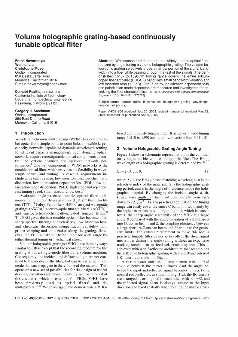
By simulating the Bragg diffraction of different Gauss-ian beam sizes from the holographic grating, Fig. 3 showsthat the IL of a 500-m-diam input beam increases 1.5 dBalong the tuning angle 10 to 18 deg. To decrease the IL
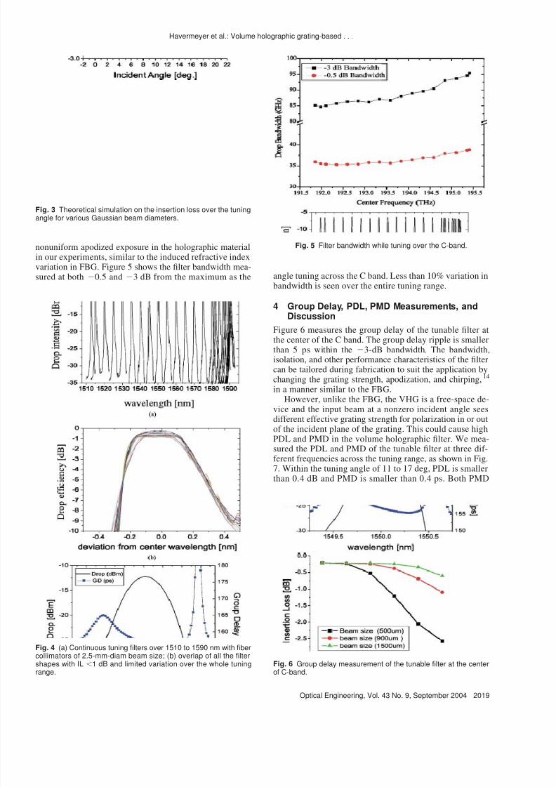
variation 0.5 dB over the C band, the collimated beamsize needs to be 1.5 mm in diam. Figure 4 shows theexperimental tuning filters with similar devices in Fig. 1with collimators of 2.5-mm beam size. The tuning rangecovers 1510 to 1590 nm, and the IL variation is smallerthan 0.7 dB, as shown in Fig. 4b. The larger than expectedIL variation is random instead of systematically goingdown as the tuning angle increases, which could be contrib-uted from other measurement noise such as the stability of the angular tuning and the extreme angular coupling sensi-tivity of the large beam collimator. The nonsymmetric filtershape, as shown in Fig. 4b, is possibly caused by thenonuniform refractive index along the grating due to the
Fig. 1 (a) A normal retroreflector with two perpendicular mirrors.The reflected beam is fixed when the retroreflector is rotated aroundthe mirror joint. (b) Replacing one mirror by a VHG. The continu-ously tunable wavelength of this optical filter is determined by theVHG incident angle .
Fig. 2 (a) Continuous tuning filters over C-band with fiber collima-tors of 0.5-mm-diam beam size; (b) overlap of all the filter shapeswith limited variation over the whole tuning range.
Havermeyer et al.: Volume holographic grating-based . . .
2018 Optical Engineering, Vol. 43 No. 9, September 2004
8/8/2019 VHG Tunable Filter 2004
http://slidepdf.com/reader/full/vhg-tunable-filter-2004 3/5
nonuniform apodized exposure in the holographic materialin our experiments, similar to the induced refractive indexvariation in FBG. Figure 5 shows the filter bandwidth mea-
sured at both 0.5 and 3 dB from the maximum as the angle tuning across the C band. Less than 10% variation inbandwidth is seen over the entire tuning range.
4 Group Delay, PDL, PMD Measurements, andDiscussion
Figure 6 measures the group delay of the tunable filter atthe center of the C band. The group delay ripple is smallerthan 5 ps within the 3-dB bandwidth. The bandwidth,isolation, and other performance characteristics of the filtercan be tailored during fabrication to suit the application bychanging the grating strength, apodization, and chirping,14
in a manner similar to the FBG.However, unlike the FBG, the VHG is a free-space de-
vice and the input beam at a nonzero incident angle seesdifferent effective grating strength for polarization in or outof the incident plane of the grating. This could cause highPDL and PMD in the volume holographic filter. We mea-sured the PDL and PMD of the tunable filter at three dif-ferent frequencies across the tuning range, as shown in Fig.7. Within the tuning angle of 11 to 17 deg, PDL is smallerthan 0.4 dB and PMD is smaller than 0.4 ps. Both PMD
Fig. 3 Theoretical simulation on the insertion loss over the tuningangle for various Gaussian beam diameters.
Fig. 4 (a) Continuous tuning filters over 1510 to 1590 nm with fibercollimators of 2.5-mm-diam beam size; (b) overlap of all the filtershapes with IL 1 dB and limited variation over the whole tuningrange.
Fig. 5 Filter bandwidth while tuning over the C-band.
Fig. 6 Group delay measurement of the tunable filter at the centerof C-band.
Havermeyer et al.: Volume holographic grating-based . . .
2019Optical Engineering, Vol. 43 No. 9, September 2004

8/8/2019 VHG Tunable Filter 2004
http://slidepdf.com/reader/full/vhg-tunable-filter-2004 4/5

8/8/2019 VHG Tunable Filter 2004
http://slidepdf.com/reader/full/vhg-tunable-filter-2004 5/5
Christophe Moser is co-founder and CEOof Ondax. Prior to founding Ondax, Dr.Moser held management positions in theoptical measurement system division ofTESA-Brown & Sharpe in Switzerland, andat Holoplex, an optical data storagestart-up in Pasadena, California. During histhesis at Caltech, he developed devicesand processes that are at the core ofOndax’s technology. He received his PhD
in electrical engineering from Caltech.
Demetri Psaltis is the Thomas G. MyersProfessor of Electrical Engineering atCaltech in Pasadena, California. He waseducated at Carnegie-Mellon Universitywhere he received a BS degree in electri-cal engineering and economics in 1974, amaster’s in 1975, and a PhD in electricalengineering in 1977. In 1980, he joined thefaculty at the California Institute of Technol-ogy, Pasadena, California, and he servedas executive officer for the Computation
and Neural Systems Department from 1992 to 1996. From 1996
until 1999 he was the director of the National Science Foundationresearch center on Neuromorphic Systems Engineering at Caltech.He is currently director of the Center for Optofluidic Integration atCaltech. His research interests are in optical information processing,holography, optical networks, imaging, optical memories, and opticaldevices. He has authored or co-authored more than 300 publica-tions in these areas. Dr. Psaltis is a fellow of the Optical Society ofAmerica and SPIE. He received the International Commission ofOptics Prize and the Humboldt Award. He is a chairman and co-founder of Ondax.
Gregory J. Steckman received his BSfrom the University of California, San Di-ego, in 1995 and his MS and PhD from theCalifornia Institute of Technology in 1997and 2000, respectively, all in electrical en-gineering. He is currently the director of en-gineering at Ondax, Inc., responsible forthe research and design of new products.Dr. Steckman has authored or co-authorednumerous publications on the subject ofvolume holography.
Havermeyer et al.: Volume holographic grating-based . . .
2021Optical Engineering, Vol. 43 No. 9, September 2004


![Mid-infrared Vernier racetrack resonator tunable filter ... · Mid-infrared Vernier racetrack resonator tunable filter implemented on a germanium on SOI waveguide platform [Invited]](https://img.dokumen.tips/doc/110x75/5f4c8a2be860f8783803843f/mid-infrared-vernier-racetrack-resonator-tunable-filter-mid-infrared-vernier.jpg)