Embed Size (px)
Citation preview

INSTRUCTION MANUAL
This device complies with Part 15 ofthe FCC rules. Operation is subject tothe condition that this device does notcause harmful interference.
UHF TRANSCEIVER
iF60
VHF TRANSCEIVER
iF50
IC-F50_F60_MDC-2.qxd 06.11.17 4:39 PM Page A (1,1)

i
SAFETY TRAINING INFORMATIONYour Icom radio generates RF electromagnetic energyduring transmit mode. This radio is designed for and clas-sified as “Occupational Use Only”, meaning it must beused only during the course of employment by individualsaware of the hazards, and the ways to minimize such haz-ards. This radio is NOT intended for use by the “GeneralPopulation” in an uncontrolled environment.
This radio has been tested and complies with the FCC RF exposure lim-its for “Occupational Use Only”. In addition, your Icom radio complies withthe following Standards and Guidelines with regard to RF energy andelectromagnetic energy levels and evaluation of such levels for exposureto humans:
• FCC OET Bulletin 65 Edition 97-01 Supplement C, Evaluating Com-pliance with FCC Guidelines for Human Exposure to Radio Fre-quency Electromagnetic Fields.
• American National Standards Institute (C95.1-1992), IEEE Standardfor Safety Levels with Respect to Human Exposure to Radio Fre-quency Electromagnetic Fields, 3 kHz to 300 GHz.
• American National Standards Institute (C95.3-1992), IEEE Recom-mended Practice for the Measurement of Potentially Hazardous Elec-tromagnetic Fields– RF and Microwave.
• The following accessories are authorized for use with this product.Use of accessories other than those specified may result in RF ex-posure levels exceeding the FCC requirements for wireless RF ex-posure.; Belt Clip (MB-98), Rechargeable Li-Ion Battery Pack(BP-227), Alkaline Battery Case (BP-226) and Speaker-microphone(HM-138).
To ensure that your expose to RF electromagneticenergy is within the FCC allowable limits for occupa-tional use, always adhere to the following guidelines:
CAUTION
W ARNING
IC-F50_F60_MDC-2.qxd 06.11.17 4:39 PM Page i (1,1)

ii
ION• DO NOT operate the radio without a proper antenna attached, as this
may damaged the radio and may also cause you to exceed FCC RFexposure limits. A proper antenna is the antenna supplied with thisradio by the manufacturer or antenna specifically authorized by themanufacturer for use with this radio.
• DO NOT transmit for more than 50% of total radio use time (“50%duty cycle”). Transmitting more than 50% of the time can cause FCCRF exposure compliance requirements to be exceeded. The radio istransmitting when the “TX indicator” lights red. You can cause theradio to transmit by pressing the “PTT” switch.
• ALWAYS keep the antenna at least 2.5 cm (1 inch) away from thebody when transmitting and only use the Icom belt-clip which is listedon page vi when attaching the radio to your belt, etc., to ensure FCCRF exposure compliance requirements are not exceeded. To providethe recipients of your transmission the best sound quality, hold theantenna at least 5 cm (2 inches) from your mouth, and slightly off toone side.
The information listed above provides the user with the informationneeded to make him or her aware of RF exposure, and what to do to as-sure that this radio operates with the FCC RF exposure limits of this radio.
Electromagnetic Interference/CompatibilityDuring transmissions, your Icom radio generates RF energy that can pos-sibly cause interference with other devices or systems. To avoid such in-terference, turn off the radio in areas where signs are posted to do so.DO NOT operate the transmitter in areas that are sensitive to electro-magnetic radiation such as hospitals, aircraft, and blasting sites.
Occupational/Controlled UseThe radio transmitter is used in situations in which persons are exposedas consequence of their employment provided those persons are fullyaware of the potential for exposure and can exercise control over theirexposure.
IC-F50_F60_MDC-2.qxd 06.11.17 4:39 PM Page ii (1,1)

iii
FOREWORDREAD ALL INSTRUCTIONS carefully and completely beforeusing the transceiver.
SAVE THIS INSTRUCTION MANUAL— This instructionmanual contains important operating instructions for the IC-F50 VHF
TRANSCEIVER and IC-F60 UHF TRANSCEIVER.
EXPLICIT DEFINITIONS
OPERATING NOTES• When transmitting with a portable radio, hold the radio in a vertical po-
sition with its microphone 5 to 10 centimeters (2 to 4 inches) awayfrom your mouth. Keep the antenna at least 2.5 centimeters (1 inch)from your head and body.
• If you wear a portable two-way radio on your body, ensure that the an-tenna is at least 2.5 centimeters (1 inch) from your body when trans-mitting.
WORD DEFINITION
RWARNING Personal injury, fire hazard or electric shock may occur.
NOTE If disregarded, inconvenience only. No risk of personal injury, fire or electric shock.
CAUTION Equipment damage may occur.
Icom, Icom Inc. and the logo are registered trademarks of Icom Incorpo-rated (Japan) in the United States, the United Kingdom, Germany, France, Spain,Russia and/or other countries.
IC-F50_F60_MDC-2.qxd 06.11.17 4:39 PM Page iii (1,1)
iv
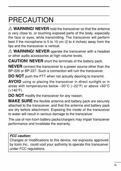
PRECAUTIONR WARNING! NEVER hold the transceiver so that the antennais very close to, or touching exposed parts of the body, especiallythe face or eyes, while transmitting. The transceiver will performbest if the microphone is 5 to 10 cm (2 to 4 inches) away from thelips and the transceiver is vertical.
R WARNING! NEVER operate the transceiver with a headsetor other audio accessories at high volume levels.
CAUTION! NEVER short the terminals of the battery pack.
NEVER connect the transceiver to a power source other than theBP-226 or BP-227. Such a connection will ruin the transceiver.
DO NOT push the PTT when not actually desiring to transmit.
AVOID using or placing the transceiver in direct sunlight or inareas with temperatures below –30°C (–22°F) or above +60°C(+140°F).
DO NOT modify the transceiver for any reason.
MAKE SURE the flexible antenna and battery pack are securelyattached to the transceiver, and that the antenna and battery packare dry before attachment. Exposing the inside of the transceiverto water will result in serious damage to the transceiver.
The use of non-Icom battery packs/chargers may impair transceiverperformance and invalidate the warranty.
FCC caution:Changes or modifications to this device, not expressly approvedby Icom Inc., could void your authority to operate this transceiverunder FCC regulations.
IC-F50_F60_MDC-2.qxd 06.11.17 4:39 PM Page iv (1,1)

TABLE OF CONTENTS
v
SAFETY TRAINING INFORMATION …………………………………… iFOREWORD ……………………………………………………………… iiiEXPLICIT DEFINITIONS ………………………………………………… iiiOPERATING NOTES …………………………………………………… iiiPRECAUTION …………………………………………………………… ivTABLE OF CONTENTS ………………………………………………… vSUPPLIED ACCESSORIES …………………………………………… vi1 ACCESSORIES ……………………………………………………… 1–2
‘ Accessory attachments……………………………………………… 12 PANEL DESCRIPTION …………………………………………… 3–11
‘ Front, top and side panels ………………………………………… 3‘ Function display ……………………………………………………… 6‘ Programmable function keys ……………………………………… 7
3 CONVENTIONAL OPERATION ………………………………… 12–18‘ Turning power ON ………………………………………………… 12‘ Channel selection ………………………………………………… 12‘ Call procedure ……………………………………………………… 13‘ Receiving and transmitting ……………………………………… 14‘ Scrambler function ………………………………………………… 17‘ User set mode ……………………………………………………… 18
4 BIIS OPERATION ………………………………………………… 19–34‘ Default setting ……………………………………………………… 19‘ Receiving a call …………………………………………………… 20‘ Transmitting a call ………………………………………………… 23‘ Receiving a message ……………………………………………… 26‘ Transmitting a status ……………………………………………… 29‘ Transmitting an SDM ……………………………………………… 30‘ Position data transmission ………………………………………… 31‘ Printer connection ………………………………………………… 32‘ PC connection ……………………………………………………… 32‘ Digital ANI …………………………………………………………… 32‘ Auto emergency transmission …………………………………… 33‘ Stun function………………………………………………………… 33‘ BIIS indication ……………………………………………………… 34‘ Priority A channel selection ……………………………………… 34
5 MDC 1200 OPERATION ………………………………………… 35–43‘ MDC 1200 system operation ……………………………………… 35‘ Transmitting a call ………………………………………………… 36‘ Receiving a call …………………………………………………… 42
IC-F50_F60_MDC-2.qxd 06.11.17 4:39 PM Page v (1,1)

vi
6 BATTERY CHARGING ………………………………………… 44–52‘ Battery charging …………………………………………………… 44‘ Caution ……………………………………………………………… 45‘ Optional battery chargers ………………………………………… 46‘ Optional battery case ……………………………………………… 51
7 SPEAKER-MICROPHONE ……………………………………… 53–54‘ Optional HM-138 description ……………………………………… 53‘ Attachment ………………………………………………………… 54
8 OPTIONS ………………………………………………………… 55–56
SUPPLIED ACCESSORIESThe following accessories are supplied: Qty.• Flexible antenna . . . . . . . . . . . . . . . . . . . . . . . . . . . . . . . . . . . . . . . .1• Battery pack . . . . . . . . . . . . . . . . . . . . . . . . . . . . . . . . . . . . . . . . . . . .1• Jack cover . . . . . . . . . . . . . . . . . . . . . . . . . . . . . . . . . . . . . . . . . . . . .1• Belt clip . . . . . . . . . . . . . . . . . . . . . . . . . . . . . . . . . . . . . . . . . . . . . . .1• Function name stickers* (KEY-STICKER) . . . . . . . . . . . . . . . . . . . . .1
*There are no names on the programmable function keys since the func-tions can be freely assigned to [P0] to [P3], [Red], [ ] and [ ] keys.Attach the supplied function name stickers above the appropriate keys foreasy recognition of that key’s assigned function.
Versions of the IC-F50/F60 which display the “FM AP-PROVED” symbol as at left on the serial number seal, con-form to intrinsically safe ratings of the FMRC (Factory MutualResearch Corporation).
Intrinsically safe : Class I, II, III, Division 1, Groups C, D, E, F, GNonincendive : Class I, Division 2, Groups A, B, C, DConnected battery pack : BP-227FM
The repair and maintenance of an FM approved transceiver can only be per-formed in an Factory Mutual approved repair facility. The FM approval will be can-celed if FM intrinsically safe radios are repaired anywhere else except in anapproved facility.
IC-F50_F60_MDC-2.qxd 06.11.17 4:39 PM Page vi (1,1)

1
1 ACCESSORIES� Accessory attachmentsD Flexible antennaConnect the supplied flexible antennato the antenna connector.
CAUTION!• NEVER HOLD by the antenna
when carrying the transceiver.• Transmitting without an antenna
may damage the transceiver.
ï Battery packTo attach the battery pack:Slide the battery pack on the back of the transceiver in the direc-tion of the arrow (q), then lock it with the battery release button.• Slide the battery pack until the battery release button makes a ‘click’
sound.
To release the battery pack:Push the battery release button in the direction of the arrow (w) asshown below. The battery pack is then released.
q
w
Battery pack
Battery release button
NEVER release or at-tach the battery packwhen the transceiveris wet or soiled. Thismay result water ordust getting into thetransceiver/batterypack and may resultin the transceiverbeing damaged.
IC-F50_F60_MDC-2.qxd 06.11.17 4:39 PM Page 1 (1,1)

2
1ACCESSORIES
1ï Jack coverAttach the jack cover when the optional speaker-microphone is notused.
D Belt clipAttach the belt clip to the back of the transceiver with the suppliedscrews.
Supplied screws
q
w
e
r
To attach the jack cover:q Insert the jack cover into the
[SP MIC] connector.w Tighten the screw.
To detach the jack cover:e Unscrew the screw with a
phillips screwdriver.r Detach the jack cover for the
speaker-microphone connec-tion.
IC-F50_F60_MDC-2.qxd 06.11.17 4:39 PM Page 2 (1,1)

3
2 PANEL DESCRIPTION� Front, top and side panels
NOTE: If the speaker netting (for dust proofing) becomes wet,dry it with a hair drier (cool mode) etc. before operating the trans-ceiver. Otherwise the audio may be difficult to hear for loss ofthe sound pressure.
q VOLUME CONTROL [VOL]Turns power ON and adjusts the audio level.
w RED BUTTONThe desired function can be assigned by your dealer.
e ANTENNA CONNECTORConnects the supplied antenna.
q
i
u
w
e
r
t
y
MicrophoneFunction display(p. 6)
Speaker(See the following NOTE.)
IC-F50_F60_MDC-2.qxd 06.11.17 4:39 PM Page 3 (1,1)

4
2PANEL DESCRIPTION
2r SPEAKER-MICROPHONE CONNECTOR [SP MIC]
Connects the optional speaker-microphone. (p. 54)
t DEALER-PROGRAMMABLE KEYS [P0] to [P3]The desired functions can be assigned independently by yourdealer.
y CH UP AND DOWN KEYS [ ]/[ ]➥ During standby condition, push to select an operating channel.➥ After pushing [TX Code CH Select], push to select a TX code
channel.➥ After pushing [DTMF Autodial], push to select a DTMF channel.➥ After pushing and holding [Scan A Start/Stop]/[Scan B
Start/Stop], push to select a scan group.➥ After pushing [Digital], push to select a BIIS code, status num-
ber or SDM.*Desired functions can be assigned independently by your dealer.
u TRANSMIT/BUSY INDICATORLights red while transmitting; lights green while receiving a sig-nal, or when the squelch is open.
i PTT SWITCH [PTT]Push and hold to transmit; release to receive.
[SP MIC] jack cover
NOTE: KEEP the [SP MIC] jack cover attached to the transceiver when the speaker-microphone is not used. (See p. 2 for details)
IC-F50_F60_MDC-2.qxd 06.11.17 4:39 PM Page 4 (1,1)

5
2 PANEL DESCRIPTION
� Function display
q OUTPUT POWER INDICATORAppears when Low 2 or Low 1 is selected.
w AUDIBLE INDICATOR➥ Appears when the channel is in the ‘audible’ (unmute) condi-
tion.➥ Appears when the specified 2/5-tone/BIIS code is received.
e COMPANDER INDICATOR Appears when the compander function is activated.
r KEY LOCK INDICATOR Appears during the key lock function ON.
t SCRAMBLER INDICATORAppears when the voice scrambler function is activated.
y BELL INDICATORAppears/blinks when the specific 2/5-tone/BIIS code is received,according to the programming.
u BATTERY INDICATORAppears or blinks when the battery power decreases to a speci-fied level.
i ALPHANUMERIC DISPLAYDisplays the operating channel number, channel names, Setmode contents, DTMF numbers, etc.
r uy
i
tewq
IC-F50_F60_MDC-2.qxd 06.11.17 4:39 PM Page 5 (1,1)

6
2PANEL DESCRIPTION
2
� Programmable function keysThe following functions can be assigned to [P0], [P1], [P2], [P3],[Red], [ ] and [ ] programmable function keys. Consult your Icom dealer or system operator for details concerningyour transceivers programming.If the programmable function names are bracketed in the followingexplanations, the specific switch used to activate the function de-pends on programming.
CH UP AND DOWN KEYS• Select an operating channel.• Select a transmit code channel after pushing the [TX Code CH
Select] keys.• Select a DTMF channel after pushing the [DTMF Autodial] key.• Select a scan group after pushing and holding the [Scan A
Start/Stop]/[Scan B Start/Stop] keys.• Select a BIIS code, status number or SDM after pushing the
[Digital] key.• Push to select the MDC menu after pushing [MDC CALL].• Push to select the desired transceiver alias or message channel
while in the transceiver alias or message channel selection mode.
BANK SELECT KEYPush this key, then push [CH Up] or [CH Down] to select the de-sired bank.
SCAN START/STOP KEYS➥ Push this key to start scanning; and push again to stop.➥ Push and hold this key to indicate the scan group, then select
the desired scan group using [CH Up]/[CH Down].
SCAN TAG KEYAdds or deletes the selected channel to the scan group.
IC-F50_F60_MDC-2.qxd 06.11.17 4:39 PM Page 6 (1,1)
7
2 PANEL DESCRIPTION
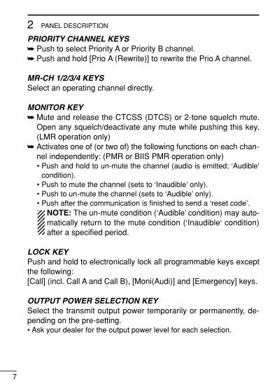
PRIORITY CHANNEL KEYS➥ Push to select Priority A or Priority B channel.➥ Push and hold [Prio A (Rewrite)] to rewrite the Prio A channel.
MR-CH 1/2/3/4 KEYSSelect an operating channel directly.
MONITOR KEY➥ Mute and release the CTCSS (DTCS) or 2-tone squelch mute.
Open any squelch/deactivate any mute while pushing this key.(LMR operation only)
➥ Activates one of (or two of) the following functions on each chan-nel independently: (PMR or BIIS PMR operation only)• Push and hold to un-mute the channel (audio is emitted; ‘Audible’
condition).• Push to mute the channel (sets to ‘Inaudible’ only).• Push to un-mute the channel (sets to ‘Audible’ only).• Push after the communication is finished to send a ‘reset code’.
NOTE: The un-mute condition (‘Audible’ condition) may auto-matically return to the mute condition (‘Inaudible‘ condition)after a specified period.
LOCK KEYPush and hold to electronically lock all programmable keys exceptthe following:[Call] (incl. Call A and Call B), [Moni(Audi)] and [Emergency] keys.
OUTPUT POWER SELECTION KEYSelect the transmit output power temporarily or permanently, de-pending on the pre-setting.• Ask your dealer for the output power level for each selection.
IC-F50_F60_MDC-2.qxd 06.11.17 4:39 PM Page 7 (1,1)

8
2PANEL DESCRIPTION
2
C.TONE CHANNEL ENTER KEYSelect the continuous tone channel using [CH Up]/[CH Down] keysto change the tone frequency/code setting after pushing this key forpermanent operation.
TALK AROUND KEYTurn the talk around function ON and OFF.• The talk around function equalizes the transmit frequency to the re-
ceive frequency for transceiver-to-transceiver communication.
WIDE/NARROW KEYPush to toggle the IF bandwidth between wide and narrow.• The wide passband width can be selected from 25.0 or 20.0 kHz using
the CS-F50 CLONING SOFTWARE. (PMR or BIIS PMR operation only)Ask your dealer for details.
DTMF AUTODIAL KEY➥ Push to enter the DTMF channel selection mode. Then select
the desired DTMF channel using [CH Up]/[CH Down] keys.➥ After selecting the desired DTMF channel, push this key to trans-
mit the DTMF code.
DTMF RE-DIAL KEYPush to transmit the last-transmitted DTMF code.
CALL KEYSPush to transmit a 2/5-tone/BIIS ID code.• Call transmission is necessary before you call another station de-
pending on your signalling system.• The [Call A] and/or [Call B] keys may be available when your system
employs selective ‘Individual/Group’ calls. Ask your dealer which call isassigned to each key.
IC-F50_F60_MDC-2.qxd 06.11.17 4:39 PM Page 8 (1,1)
9
2 PANEL DESCRIPTION
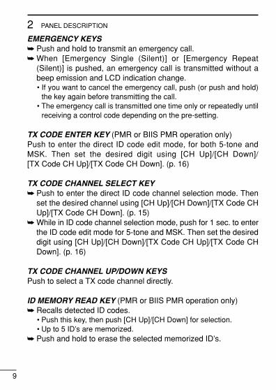
EMERGENCY KEYS➥ Push and hold to transmit an emergency call.➥ When [Emergency Single (Silent)] or [Emergency Repeat
(Silent)] is pushed, an emergency call is transmitted without abeep emission and LCD indication change.• If you want to cancel the emergency call, push (or push and hold)
the key again before transmitting the call.• The emergency call is transmitted one time only or repeatedly until
receiving a control code depending on the pre-setting.
TX CODE ENTER KEY (PMR or BIIS PMR operation only)Push to enter the direct ID code edit mode, for both 5-tone andMSK. Then set the desired digit using [CH Up]/[CH Down]/[TX Code CH Up]/[TX Code CH Down]. (p. 16)
TX CODE CHANNEL SELECT KEY➥ Push to enter the direct ID code channel selection mode. Then
set the desired channel using [CH Up]/[CH Down]/[TX Code CHUp]/[TX Code CH Down]. (p. 15)
➥ While in ID code channel selection mode, push for 1 sec. to enterthe ID code edit mode for 5-tone and MSK. Then set the desireddigit using [CH Up]/[CH Down]/[TX Code CH Up]/[TX Code CHDown]. (p. 16)
TX CODE CHANNEL UP/DOWN KEYSPush to select a TX code channel directly.
ID MEMORY READ KEY (PMR or BIIS PMR operation only)➥ Recalls detected ID codes.
• Push this key, then push [CH Up]/[CH Down] for selection.• Up to 5 ID’s are memorized.
➥ Push and hold to erase the selected memorized ID’s.
IC-F50_F60_MDC-2.qxd 06.11.17 4:39 PM Page 9 (1,1)

10
2PANEL DESCRIPTION
2
VOICE SCRAMBLER FUNCTIONPush to toggle the voice scrambler function ON and OFF.
COMPANDER KEYPush to toggle the compander function ON and OFF. The compander function reduces noise components from the trans-mitting audio to provide clear communication.
USER SET MODE KEY➥ Push and hold to enter user set mode.
• During user set mode, push this key to select an item, and push[CH Up]/[CH Down] to change the value or condition.
➥ Push and hold this key again to exit user set mode.• User set mode is also available via the ‘Power ON function’. Please
refer to p. 18 also.
DIGITAL KEY (BIIS operation only)➥ Push to select the call ID list, transmit message and standby
condition. Toggles between queue channel and received mes-sage record indication after queue channel is selected.
➥ Push and hold to select queue channel indication.
STATUS UP/DOWN KEYS (BIIS operation only)➥ While in the standby condition, push to display the transmit sta-
tus indication and select a status number.➥ When a received SDM is displayed, push to cancel the automatic
scroll and scroll the message manually.➥ When an SDM that contains more than 8 characters is displayed,
push to scroll the message manually.
IC-F50_F60_MDC-2.qxd 06.11.17 4:39 PM Page 10 (1,1)

11
2 PANEL DESCRIPTION
MDC CALL KEY (MDC operation only)➥ Push to enter the MDC menu selection mode. Then select
the desired MDC menu from “SELCALL,” “MSG,” “STATUS,”“RADIOCHK” and “CALALERT” using [CH Up]/[CH Down]/[MDC Up]/[MDC Down].After selection, push this key again to enter the transceiveralias or message channel selection mode.
➥ While in the transceiver alias or message channel selectionmode, push to return to the MDC menu selection mode.
MDC UP AND DOWN KEYS (MDC operation only)➥ Push to select the MDC menu after pushing [MDC CALL].➥ Push to select the desired transceiver alias or message chan-
nel while in the transceiver alias or message channel selec-tion mode.
MDC SELCALL KEY (MDC operation only)Push to enter the transceiver alias selection mode.• After the desired alias selection, push [PTT] to transmit a selective call.
MDC CALLALERT KEY (MDC operation only)Push to enter the transceiver alias selection mode.• After the desired alias selection, push [PTT] to transmit a call alert.
IC-F50_F60_MDC-2.qxd 06.11.17 4:39 PM Page 11 (1,1)

12
3CONVENTIONAL OPERATION
2
3
� Turning power ONq Rotate [VOL] to turn power ON.w If the transceiver is programmed for a start up passcode, input
digit codes as directed by your dealer.• The keys in the table below can be used for password input:• The transceiver detects numbers in the same block as identical.
Therefore “01234” and “56789” are the same.
e When the “PASSWORD” indication does not clear after inputting4 digits, the input code number may be incorrect. Turn the poweroff and start over in this case.
� Channel selectionSeveral types of channel selections are available. Methods may dif-fer according to your system set up.
NON-BANK TYPE:Push [ ]/[ ] to select the desired operating channel, in se-quence; or, push one of the [MR-CH 1] to [MR-CH 4] keys to selecta channel directly.
BANK-TYPE:Push [Bank], then push [ ] or [ ] to select the desired bank.
AUTOMATIC SCAN TYPE:Channel setting is not necessary for this type. When turning thepower ON, the transceiver automatically starts scanning. Scanningstops when receiving a call.
KEY
NUMBER0
5
4
9
3
8
2
7
1
6
IC-F50_F60_MDC-2.qxd 06.11.17 4:39 PM Page 12 (1,1)

13
3 CONVENTIONAL OPERATION
� Call procedureWhen your system employs tone signalling (excluding CTCSS andDTCS), the call procedure may be necessary prior to voice trans-mission. The tone signalling employed may be a selective callingsystem which allows you to call specific station(s) only and preventunwanted stations from contacting you.
q Select the desired TX code channel or 2/5-tone code accordingto your System Operator’s instructions.• This may not be necessary depending on programming.• Refer to pgs. 15, 16 for selection.
w Push the call switch (assigned to one of the dealer programma-ble switches: [P0], [P1], [P2], [P3], [Red], [ ] and [ ]).
e After transmitting a 2/5-tone code, the remainder of your com-munication can be carried out in the normal fashion.
Selective calling Non-selective calling
IC-F50_F60_MDC-2.qxd 06.11.17 4:39 PM Page 13 (1,1)

14
3CONVENTIONAL OPERATION
3
� Receiving and transmittingNOTE: Transmitting without an antenna may damage the trans-ceiver. See p. 1 for antenna attachment.
Receiving:q Rotate [VOL] to turn power ON.w Push [ ] or [ ] to select a channel.e When receiving a call, adjust the audio output level to a comfort-
able listening level.
Transmitting:Wait for the channel to become clear to avoid interference.q While pushing and holding [PTT], speak into the microphone at a
normal voice level.• When a tone signalling system is used, the call procedure de-
scribed at left may be necessary.w Release [PTT] to return to receive.
IMPORTANT: To maximize the readability of your signal;1. Pause briefly after pushing [PTT].2. Hold the microphone 5 to 10 cm (2 to 4 inches) from your
mouth, then speak into the microphone at a normal voicelevel.
IC-F50_F60_MDC-2.qxd 06.11.17 4:39 PM Page 14 (1,1)

15
3 CONVENTIONAL OPERATION
D Transmitting notes• Transmit inhibit functionThe transceiver has several inhibit functions which restrict trans-mission under the following conditions:
- The channel is in mute condition (‘Inaudible’ condition; “ ”does not appear).
- Channel is busy.- Un-matched (or matched) CTCSS is received.- The selected channel is a ‘receive only’ channel.
• Time-out timerAfter continuous transmission for the pre-programmed time period, thetime-out timer is activated, causing the transceiver to stop transmitting.• Penalty timerOnce the time-out timer is activated, transmission is further inhibitedfor a period determined by the penalty timer.
D TX code channel selectionIf the transceiver has [TX Code CH Select] assigned to it, indica-tion can be toggled between the operating channel number (orname) and TX code channel number (or name). When the TX codechannel number (or name) is displayed, the [ ]/[ ] key selectsthe TX code channel.
TO SELECT A TX CHANNEL:q Push [TX Code CH Select]— a TX code channel appears.w Push [ ]/[ ] to select the desired TX code channel.e Push [Call] (or [PTT] during MSK operation) to transmit the se-
lected TX code.r Push [TX Code CH Select] again to return to the operating chan-
nel number indication.
FOR TX CODE CHANNEL TYPE:If the transceiver has a [TX Code CH Up] or [TX Code CH Down]key assignment, the programmed TX code channel can be selecteddirectly.
IC-F50_F60_MDC-2.qxd 06.11.17 4:39 PM Page 15 (1,1)

16
3CONVENTIONAL OPERATION
3
D TX code number edit (PMR or BIIS PMR operation only)If the transceiver has [TX Code CH Select] or [TX Code Enter] as-signed to it, TX code contents can be edited within the allowabledigits.
TO EDIT A TX CODE VIA [TX CODE CH SELECT] KEY:q Push [TX Code CH Select] to enter the TX code channel selec-
tion mode.• Select the desired channel using [ ]/[ ] if necessary.
w Push [TX Code CH Select] for 1 sec. to enter the TX code editmode.
e Push [TX Code CH Select] to select the desired digit to beedited.
r Set the desired digit using [ ]/[ ]/[TX Code CH Up]/[TXCode CH Down].
t Push [TX Code CH Select] to set the digit. The editable digit willmove to the right automatically.
y Repeat r and t to input all allowable digits.u Push [Call] or [PTT] to transmit the selected TX code.
TO EDIT A TX CODE VIA [TX CODE ENTER] KEY:q Select the desired TX code channel via [TX Code CH Up]/[TX
Code CH Down].w Push [TX Code Enter] to enter the TX code edit mode.e Push [TX Code Enter] to select the desired digit to be edited.r Set the desired digit using [ ]/[ ]/[TX Code CH Up]/[TX
Code CH Down].t Push [TX Code Enter] to set the digit. The editable digit will move
to the right automatically.y Repeat r and t to input all allowable digits.u Push [Call] or [PTT] to transmit the selected TX code.
IC-F50_F60_MDC-2.qxd 06.11.17 4:39 PM Page 16 (1,1)

17
3 CONVENTIONAL OPERATION
D DTMF transmissionIf the transceiver has [DTMF Autodial] assigned to it, the automaticDTMF transmission function is available. Up to 8 DTMF channelsare available.
TO SELECT A TX CODE:q Push [DTMF Autodial]— a DTMF channel appears.w Push [ ]/[ ] to select the desired DTMF channel.e Push [DTMF Autodial] to transmit the DTMF code in the selected
DTMF channel.
� Scrambler functionThe voice scrambler function provides private communication be-tween stations. The frequency inversion type is equipped to all ver-sions, and some versions have the Rolling or Non-rolling typeinstalled.
q Push [Scrambler] to turn the scrambler function ON.w “ ” appears.e Push [Scrambler] again to turn the scrambler function OFF.
IC-F50_F60_MDC-2.qxd 06.11.17 4:39 PM Page 17 (1,1)

18
3CONVENTIONAL OPERATION
3
� User set modeUser set mode is accessed at power ON and allows you to set seldom-changed settings. In this case you can “customize” trans-ceiver operation to suit your preferences and operating style.
Entering the user set mode:q While pushing and holding [ ] and [ ], rotate [VOL] to enter
the user set mode at power ON.w Push and hold [P0] to enter user set mode. Push [P0] momen-
tarily to select the item. Then push [ ] and [ ] to set the desired level/condition.
Available set mode functions:• Backlight : ON, Auto or OFF• Beep : ON or OFF• SQL Level : 0 to 255• AF Min level : ON or OFF• Mic Gain : 1 to 5• Battery Voltage : ON or OFF
e Push and hold [P0] again to exit set mode.
User set mode is also available using a programmable key. Pleaserefer to p. 11 [User Set Mode] section.
IC-F50_F60_MDC-2.qxd 06.11.17 4:39 PM Page 18 (1,1)
19
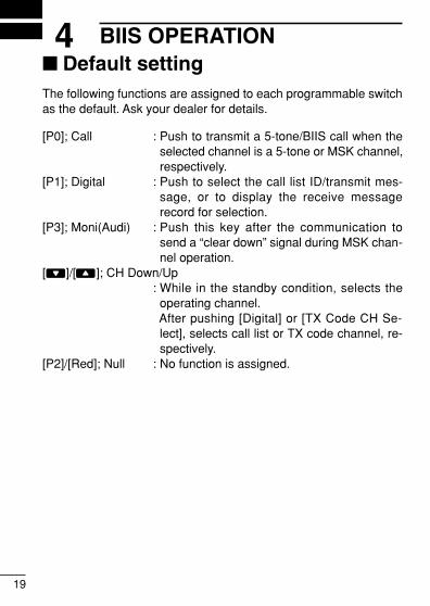
4 BIIS OPERATION� Default settingThe following functions are assigned to each programmable switchas the default. Ask your dealer for details.
[P0]; Call : Push to transmit a 5-tone/BIIS call when theselected channel is a 5-tone or MSK channel,respectively.
[P1]; Digital : Push to select the call list ID/transmit mes-sage, or to display the receive messagerecord for selection.
[P3]; Moni(Audi) : Push this key after the communication tosend a “clear down” signal during MSK chan-nel operation.
[ ]/[ ]; CH Down/Up: While in the standby condition, selects theoperating channel.After pushing [Digital] or [TX Code CH Se-lect], selects call list or TX code channel, re-spectively.
[P2]/[Red]; Null : No function is assigned.
IC-F50_F60_MDC-2.qxd 06.11.17 4:39 PM Page 19 (1,1)

20
4BIIS OPERATION
4
� Receiving a callDD Individual callq When an individual call is received;
• Beeps sound.• “ ” appears and the mute is released.
• The programmed text message (e.g.“ ”) and the callingstation ID (or text) is displayed alternately, depending on the set-ting.
• “ ” appears or blinks depending on the setting.
w Push and hold [PTT], then speak into the microphone at a nor-mal voice level.• Transmit/Busy indicator lights red.
e Release [PTT] to return to receive.• Transmit/Busy indicator lights green while receiving a signal.
r To finish the conversation, push [P3] (Moni(Audi)) to send the“Clear down” signal. • Either station can send a clear down signal.• “ ” is displayed for 2 sec. (approx.).
• “ ” disappears and the transceiver returns to the standby condi-tion.
Appears or blinksAppears
IC-F50_F60_MDC-2.qxd 06.11.17 4:39 PM Page 20 (1,1)
21
4 BIIS OPERATION
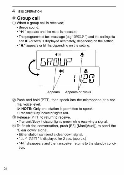
DD Group callq When a group call is received;
• Beeps sound.• “ ” appears and the mute is released.
• The programmed text message (e.g.“ ”) and the calling sta-tion ID (or text) is displayed alternately, depending on the setting.
• “ ” appears or blinks depending on the setting.
w Push and hold [PTT], then speak into the microphone at a nor-mal voice level.
NOTE: Only one station is permitted to speak.• Transmit/Busy indicator lights red.
e Release [PTT] to return to receive.• Transmit/Busy indicator lights green while receiving a signal.
r To finish the conversation, push [P3] (Moni(Audi)) to send the“Clear down” signal.• Either station can send a clear down signal.• “ ” is displayed for 2 sec. (approx.)• “ ” disappears and the transceiver returns to the standby condi-
tion.
Appears or blinksAppears
IC-F50_F60_MDC-2.qxd 06.11.17 4:39 PM Page 21 (1,1)

22
4BIIS OPERATION
4
DD Displaying the received call record— Queue indication
The transceiver memorizes the calling station IDs for record. Up to3 calls can be memorized, and the oldest call record is erasedwhen a 4th call is received. However, once the transceiver is pow-ered OFF, the all records are cleared.
q Push [P1] (Digital) for 1 sec.• Displays following indication.
When a record is available
When no record is available
w Push [ ]/[ ] to select the desired call.e Push [P1] (Digital) for 1 sec. again to return to the standby con-
dition.• When no operation is performed for 30 sec., the transceiver returns
to the standby condition automatically.
IC-F50_F60_MDC-2.qxd 06.11.17 4:39 PM Page 22 (1,1)

23
4 BIIS OPERATION
� Transmitting a callTotal of a 3 ways for code selection are available—selecting the callcode from memory, entering the call code from the keypad and call-ing back from the queue channel record.
DD Using call memoryq While in the standby condition, push [P1] (Digital) to enter the
call code memory channel selection mode.
w Push [ ]/[ ] to select the desired call code.e Push [P0] (Call) or [PTT]* to call.
*PTT call can be made only when PTT call capability is permitted.
NOTE: When no answer back is received, the transceiver re-peats the call 3 times (default) automatically, and “ ” isdisplayed during each call. However, an error beep soundsand “ ” is displayed when no answer back is receivedafter the calls.
r Push [PTT] to transmit; release to receive.t Push [P3] (Moni(Audi)) to send the “Clear down” signal.
Call code text is displayed.
IC-F50_F60_MDC-2.qxd 06.11.17 4:39 PM Page 23 (1,1)
24
4BIIS OPERATION
4
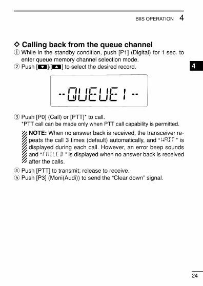
DD Calling back from the queue channelq While in the standby condition, push [P1] (Digital) for 1 sec. to
enter queue memory channel selection mode.w Push [ ]/[ ] to select the desired record.
e Push [P0] (Call) or [PTT]* to call.*PTT call can be made only when PTT call capability is permitted.
NOTE: When no answer back is received, the transceiver re-peats the call 3 times (default) automatically, and “ ” isdisplayed during each call. However, an error beep soundsand “ ” is displayed when no answer back is receivedafter the calls.
r Push [PTT] to transmit; release to receive.t Push [P3] (Moni(Audi)) to send the “Clear down” signal.
IC-F50_F60_MDC-2.qxd 06.11.17 4:39 PM Page 24 (1,1)
25
4 BIIS OPERATION
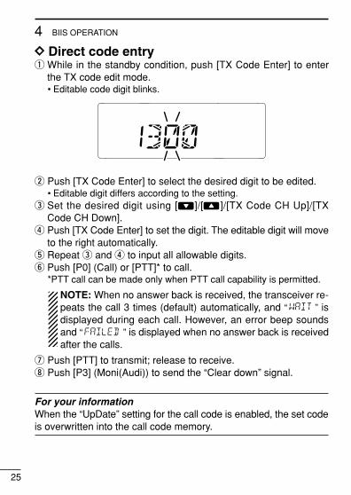
DD Direct code entryq While in the standby condition, push [TX Code Enter] to enter
the TX code edit mode.• Editable code digit blinks.
w Push [TX Code Enter] to select the desired digit to be edited.• Editable digit differs according to the setting.
e Set the desired digit using [ ]/[ ]/[TX Code CH Up]/[TXCode CH Down].
r Push [TX Code Enter] to set the digit. The editable digit will moveto the right automatically.
t Repeat e and r to input all allowable digits.y Push [P0] (Call) or [PTT]* to call.
*PTT call can be made only when PTT call capability is permitted.
NOTE: When no answer back is received, the transceiver re-peats the call 3 times (default) automatically, and “ ” isdisplayed during each call. However, an error beep soundsand “ ” is displayed when no answer back is receivedafter the calls.
u Push [PTT] to transmit; release to receive.i Push [P3] (Moni(Audi)) to send the “Clear down” signal.
For your informationWhen the “UpDate” setting for the call code is enabled, the set codeis overwritten into the call code memory.
IC-F50_F60_MDC-2.qxd 06.11.17 4:39 PM Page 25 (1,1)

26
4BIIS OPERATION
4
� Receiving a messageDD Receiving a status messageq When a status message is received;
• Beeps sound.• The calling station ID (or text) and the status message is displayed
alternately, depending on the setting.
w Push [P3] (Moni(Audi)) to return to the standby condition.
NOTE: Only the calling station ID (or text) is displayed (nomessage is displayed alternately) when the scroll timer is setto “OFF”. In this case, push [Status Up]/[Status Down] to dis-play the status message manually.
IC-F50_F60_MDC-2.qxd 06.11.17 4:39 PM Page 26 (1,1)

27
4 BIIS OPERATION
DD Receiving an SDMq When an SDM is received;
• Beeps sound.• The calling station ID (or text) and the SDM is displayed alternately,
depending on the setting.
w When the received SDM includes more than 8 characters, themessage scrolls automatically, when the automatic scroll func-tion is activated.• Push [Status Up]/[Status Down] to scroll the message manually.
e Push [P3] (Moni(Audi)) to return to the standby condition.
IC-F50_F60_MDC-2.qxd 06.11.17 4:39 PM Page 27 (1,1)

28
4BIIS OPERATION
4
DD Received message selectionThe transceiver memorizes the received messages for record. Upto 6 messages for status and SDM, or 95 character SDM’s can bememorized. The oldest message is erased when the 7th messageis received. However, once the transceiver is powered OFF, allmessages are cleared.
q Push [P1] (Digital) for 1 sec.• Displays queue memory.
w Push [P1] (Digital) momentarily.• Displays message memory.
When a message is available
When no message is available
e Push [ ]/[ ] to select the desired message.• When selecting the SDM that includes more than 8 characters, the
message scrolls automatically, when the automatic scroll function isactivated.
• Push [Status Up]/[Status Down] to scroll the message manually.r Push [P1] (Digital) for 1 sec. again to return to the standby con-
dition.• When no operation is performed for 30 sec., the transceiver returns
to the standby condition automatically.
IC-F50_F60_MDC-2.qxd 06.11.17 4:39 PM Page 28 (1,1)

29
4 BIIS OPERATION
� Transmitting a statusDD GeneralThe status message can be selected with the programmed text,and the message text is also displayed on the function display ofthe called station.Up to 24 status types (1 to 24) are available, and the status mes-sages 22 and 24 have designated meanings.
Status 22: Emergency*Status 24: GPS request*The status 22 can also be used as a normal status message by dis-abling the designated meaning. However, the status 24 is fixed.
The status call can be sent with both individual and group calls.
DD Transmitting a statusq While in the standby condition, push [P1] (Digital), then push
[ ]/[ ] to select the desired station/group code.w Push [P1] (Digital) again, then push [ ]/[ ] to select the de-
sired status message.
Or, you can select the desired status message using [StatusUp]/[Status Down] key directly.
e Push [P0] (Call) or [PTT]* to transmit the status message to theselected station/group.*PTT call can be made only when PTT call capability is permitted.• 2 beeps will sound and the transceiver returns to the standby con-
dition automatically when the transmission is successful.
Status message is displayed.
IC-F50_F60_MDC-2.qxd 06.11.17 4:39 PM Page 29 (1,1)

30
4BIIS OPERATION
4
� Transmitting an SDMDD GeneralThe short data message, SDM, can be sent to an individual stationor group stations. Also, 8 SDM memory channels are available andthe messages can be edited via PC programming.
DD Transmitting an SDMq While in the standby condition, push [P1] (Digital), then push
[ ]/[ ] to select the desired station/group code.w Push [P1] (Digital) again, then push [ ]/[ ] to select the de-
sired SDM.
Or, you can select the desired SDM using [Status Up]/[StatusDown] key directly.
e Push [P0] (Call) or [PTT]* to transmit the SDM to the selectedstation/group.*PTT call can be made only when PTT call capability is permitted.• 2 beeps will sound and the transceiver returns to the standby con-
dition automatically when the transmission is successful.
SDM is displayed.
IC-F50_F60_MDC-2.qxd 06.11.17 4:39 PM Page 30 (1,1)
31
4 BIIS OPERATION
� Position data transmissionWhen the optional OPC-966 INTERFACE CABLE and a GPS receiveris connected to the transceiver, the position (longitude and latitude)data can be transmitted automatically.Ask your dealer or system operator for connection details.
The position data is transmitted when;• Status 24 message is received
*When the status 24 message, GPS request, is received.• Fully automatic
When automatic position transmission is enabled, send the po-sition data according to ‘Time Marker’ and ‘Interval Timer’ set-tings.
• PTT is releasedWhen ‘Send with Logoff’ is enabled.- Set the “Log-In/Off” item as “L-OFF”.
• After sending a status messageWhen ‘Send with Status’ is enabled.
• After sending an SDMWhen ‘Send with SDM’ is enabled.
• After sending status 22 (Emergency)When ‘Send with Emergency’ is enabled.
IC-F50_F60_MDC-2.qxd 06.11.17 4:39 PM Page 31 (1,1)

32
4BIIS OPERATION
4
� Printer connectionWhen the optional OPC-966 INTERFACE CABLE is connected to thetransceiver, a printer can be connected to print out the receivedSDM content and the ID of the station who sent the message.Ask your dealer or system operator for connection details.
� PC connectionWhen the optional OPC-966 INTERFACE CABLE is connected to thetransceiver, a PC can be connected to provide remote control, datareception, etc.Ask your dealer or system operator for connection details.
� Digital ANIThe own ID can be transmitted each time the PTT is pushed (log-in)or released (log-off) during individual or group call communications.By receiving the ANI, the communication log can be recorded whenusing a PC dispatch application.
In addition, when using the ANI with log-in, the PTT side tone func-tion can be used to inform you that the ID is sent and voice com-munication can be performed.
IC-F50_F60_MDC-2.qxd 06.11.17 4:39 PM Page 32 (1,1)

33
4 BIIS OPERATION
� Auto emergency transmissionWhen [Emergency Single (Silent)] or [Emergency Repeat (Silent)] ispushed, an emergency signal is automatically transmitted for thespecified time period.
The status 22 (Emergency) is sent to the selected ID station, andthe position data is transmitted after the emergency signal when aGPS receiver is connected to the transceiver.
The emergency transmission is performed on the emergency chan-nel, however, when no emergency channel is specified, the signal istransmitted on the previously selected channel.
There is no change in the function display or beep emission duringautomatic emergency transmission.
� Stun functionWhen the specified ID, set as a killer ID, is received, the stun func-tion is activated.
When the killer ID is received, the transceiver switches to the pass-code required condition. Entering of the passcode via the keypad isnecessary to operate the transceiver again in this case.
IC-F50_F60_MDC-2.qxd 06.11.17 4:39 PM Page 33 (1,1)

34
4BIIS OPERATION
4
� BIIS indicationThe following indications are available for the BIIS operation on anMSK channel.
: Individual/group call is successful.
: Message (status or SDM) transmission is successful.
: No answer back is received.
: Appears during retry of the call (2nd call).
: End the communication.
: Operating channel is in the busy condition.
� Priority A channel selectionWhen one of the following operations is performed, the transceiverselects the Priority A channel automatically.
Priority A is selected when;• Clear down signal is received/transmitted
- Set the “Move to PrioA CH” item as “Clear Down”.• Turning the power ON
The Priority A channel is selected each time the transceiverpower is turned ON.
• Status callThe Priority A channel is selected when transmitting a statuscall.- Enable the “Send Status on PrioA CH” item in the MSK con-
figuration.
IC-F50_F60_MDC-2.qxd 06.11.17 4:39 PM Page 34 (1,1)

35
5 MDC 1200 OPERATION� MDC 1200 system operationThe MDC 1200 signaling system enhances your transceiver’s ca-pabilities. It allows PTT ID*, Selective Calling, Call Alert, RadioCheck, Messaging and Emergency signaling. Also, the dispatchercan stun and revive transceivers on the system.
An additional feature of MDC 1200 found in Icom transceivers iscalled aliasing. Each transceiver on the system has a unique IDnumber. Aliasing allows the substitution of an alphanumeric namefor this ID number. For transmit, you can use this alias to select atransceiver to call. For receive, the alias of the calling station is dis-played instead of the ID.
Please note that your dealer has set one of the programmable keys(P0, P1, P2, or P3) for MDC 1200 operation.
*When [PTT] is pushed or released, self ID is transmitted.
IC-F50_F60_MDC-2.qxd 06.11.17 4:39 PM Page 35 (1,1)
36
5MDC 1200 OPERATION
5
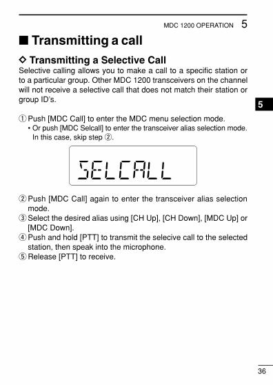
� Transmitting a callDD Transmitting a Selective CallSelective calling allows you to make a call to a specific station orto a particular group. Other MDC 1200 transceivers on the channelwill not receive a selective call that does not match their station orgroup ID’s.
qPush [MDC Call] to enter the MDC menu selection mode.• Or push [MDC Selcall] to enter the transceiver alias selection mode.
In this case, skip step w.
wPush [MDC Call] again to enter the transceiver alias selectionmode.
eSelect the desired alias using [CH Up], [CH Down], [MDC Up] or[MDC Down].
rPush and hold [PTT] to transmit the selecive call to the selectedstation, then speak into the microphone.
tRelease [PTT] to receive.
IC-F50_F60_MDC-2.qxd 06.11.17 4:39 PM Page 36 (1,1)

37
5 MDC 1200 OPERATION
DD Transmitting a Call AlertCall Alert allows you to notify another user who may be away fromthe transceiver that you want to talk.
qPush [MDC Call] to enter the MDC menu selection mode.• Or push [MDC CallAlert] to enter the transceiver alias selection
mode. In this case, skip steps w and e.wSelect “CALALERT” using [CH Up], [CH Down], [MDC Up] or
[MDC Down].
ePush [MDC Call] again to enter the transceiver alias selectionmode.
rSelect the desired alias using [CH Up], [CH Down], [MDC Up] or[MDC Down].
tPush [PTT] to transmit the call alert to the selected station.• “CA CALL” is displayed.
yRelease [PTT].• “CA OK” is displayed if the targeted station received the alert.• “CA FAIL” is displayed if the targeted station does not send an ac-
knowledgement.uAfter a specified time period has passed, the transceiver will re-
turn to receive.
IC-F50_F60_MDC-2.qxd 06.11.17 4:39 PM Page 37 (1,1)

38
5MDC 1200 OPERATION
5
DD Transmitting a Radio Check CallRadio check call allows you to determine whether another trans-ceiver is turned on, within range and on channel without requiringany action from the targeted station user.
qPush [MDC Call] to enter the MDC menu selection mode.wSelect “RADIOCHK” using [CH Up], [CH Down], [MDC Up] or
[MDC Down].
ePush [MDC Call] again to enter the transceiver alias selectionmode.
rSelect the desired alias using [CH Up], [CH Down], [MDC Up] or[MDC Down].
tPush [PTT] to transmit the radio check call to the selected sta-tion.• “RDO CHK” is displayed.
yRelease [PTT].• “CHK ACK” is displayed if the targeted station is turned ON, on
channel and within range.• “CHK FAIL” is displayed if the targeted station does not send an ac-
knowledgement.uAfter a specified time period has passed, the transceiver will re-
turn to receive.
IC-F50_F60_MDC-2.qxd 06.11.17 4:39 PM Page 38 (1,1)

39
5 MDC 1200 OPERATION
DD Transmitting a Status MessageStatus Messaging allows you to send a pre-programmed statusmessage to the dispatcher. There are 16 status codes that can besent. In addition, the dispatcher can send an MDC 1200 signal thatcauses the transceiver to automatically transmit its current status.
qPush [MDC Call] to enter the MDC menu selection mode.wSelect “STATUS” using [CH Up], [CH Down], [MDC Up] or [MDC
Down].
ePush [MDC Call] again to enter the status message selectionmode.
rSelect the desired status message using [CH Up], [CH Down],[MDC Up] or [MDC Down].
tPush [PTT] to transmit the status message to the dispatcher.• “STAT TX” is displayed.
yRelease [PTT].• “STAT OK” is displayed.• “STA FAIL” is displayed if there is no acknowledgment from the dis-
patcher.uAfter a specified time period has passed, the transceiver will re-
turn to receive.
Pre-programmed status message is displayed.
IC-F50_F60_MDC-2.qxd 06.11.17 4:39 PM Page 39 (1,1)

40
5MDC 1200 OPERATION
5
DD Transmitting a MessageThe transceiver can send a pre-programmed message to the dis-patcher. There are 16 messages that can be sent on a channel.
qPush [MDC Call] to enter the MDC menu selection mode.wSelect “MSG” using [CH Up], [CH Down], [MDC Up] or [MDC
Down].
ePush [MDC Call] again to enter the pre-programmed messageselection mode.
rSelect the desired message using [CH Up], [CH Down], [MDCUp] or [MDC Down].
tPush [PTT] to transmit the message to the dispatcher.• “MSG TX” is displayed.
yRelease [PTT].• “MSG OK” is displayed.• “MSG FAIL” is displayed if there is no acknowledgment from the
dispatcher.uAfter a specified time period has passed, the transceiver will re-
turn to receive.
Pre-programmed message is displayed.
IC-F50_F60_MDC-2.qxd 06.11.17 4:39 PM Page 40 (1,1)

41
5 MDC 1200 OPERATION
DD Emergency CallsThe MDC 1200 Emergency feature can be accessed using the[Emergency] key (p. 9). The transceiver will repeatedly send anEmergency MDC 1200 command to the dispatcher for a pro-grammed length of time until it receives an acknowledgement sig-nal.
The emergency call can be transmitted without a beep emissionand LCD indication change depends on the setting.With MDC 1200 Emergency, the transceiver can also be pro-grammed to keep the microphone open during an emergency call,allowing monitoring of the situation.Ask your dealer for details.
DD Stun and ReviveThe dispatcher can send MDC 1200 signals that will stun or reviveyour transceiver. If a Stun command is received that matches yourstation ID, the transceiver will display “SORRY” and you can not re-ceive or transmit. When a Revive command is received thatmatches your station ID, normal operation is restored.
IC-F50_F60_MDC-2.qxd 06.11.17 4:39 PM Page 41 (1,1)

42
5MDC 1200 OPERATION
5
� Receiving a callDD Receiving a Selective CallqWhen an individual call is received;
• Beeps sound, “ ” appears and “ ” blinks.• The calling station ID (or alias) and “SELCALL” are displayed alternately.
w Push and hold [PTT] and speak into the microphone.eRelease [PTT] to receive a response.
DD Receiving a Call AlertqWhen a Call Alert is received;
• Beeps sound and “ ” blinks.• The calling station ID (or alias) and “CALLALRT” are displayed al-
ternately.
w Push and hold [PTT] and speak into the microphone.eRelease [PTT] to receive a response.
Blinks
Appears Blinks
IC-F50_F60_MDC-2.qxd 06.11.17 4:39 PM Page 42 (1,1)

43
5 MDC 1200 OPERATION
DD Receiving an Emergency CallqWhen an emergency call is received;
• Beeps sound.• The calling station ID (or alias) and “EMG EMG” are displayed al-
ternately.
wTurn power OFF, change the channel, etc. to stop the beep anddisplay indication.
IC-F50_F60_MDC-2.qxd 06.11.17 4:39 PM Page 43 (1,1)
44
6BATTERY CHARGING
6
� Battery chargingPrior to using the transceiver for the first time, the battery pack mustbe fully charged for optimum life and operation.
CAUTION: To avoid damage to the transceiver, turn it OFF whilecharging.
• Recommended temperature range for charging:+10°C to +40°C (+50°F to +104°F)- The Li-Ion battery functions within –20°C to +60°C (–4°F to
+140°F)• Use the specified chargers (BC-152, BC-119N and BC-121N).
NEVER use another manufacturer’s charger.• Use the optional AC adapter (BC-147A/E) for the BC-152.• NEVER use another manufacturer’s AC adapter.
Recommendation:Charge the supplied battery pack for a maximum of up to10 hours. Li-Ion batteries are different from Ni-Cd batteries in thatit is not necessary to completely charge and discharge them toprolong the battery life. Therefore, charging the battery in inter-vals, and not for extended periods is recommended.
IC-F50_F60_MDC-2.qxd 06.11.17 4:39 PM Page 44 (1,1)
45
6 BATTERY CHARGING
� CautionCAUTION! NEVER insert battery pack/transceiver (with the bat-tery pack attached) with wet or soiled into the charger. This may re-sult in corrosion of the charger terminals or damage to the charger.The charger is not waterproof and water can easily get into it.
NEVER incinerate used battery packs. Internal battery gas maycause an explosion.
NEVER immerse the battery pack in water. If the battery pack be-comes wet, be sure to wipe it dry immediately (particularly the bat-tery terminals) BEFORE attaching it to the transceiver. Otherwise,the terminals will become corroded, or cause connection failure,etc.
NEVER short the terminals of the battery pack. Also, current mayflow into nearby metal objects, such as a necklace, etc. Therefore,be careful when carrying with, or placing near metal objects, carry-ing in handbags, etc.
AVOID leaving the battery pack in a fully charged, or completelydischarged condition for long time. It causes shorter battery life. Incase of leaving the battery pack unused for a long time, it must bekept safely after discharge, or use the battery until the battery indi-cator appears, then remove it from the transceiver.
If your battery pack seems to have no capacity even after beingcharged, fully charge the battery pack again. If the battery pack stilldoes not retain a charge (or very little), a new battery pack must bepurchased.
IC-F50_F60_MDC-2.qxd 06.11.17 4:39 PM Page 45 (1,1)
46
6BATTERY CHARGING
6
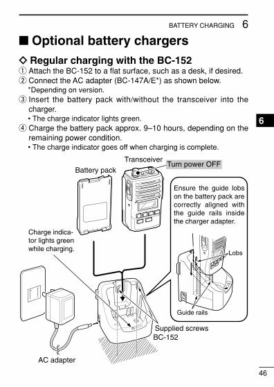
� Optional battery chargersï Regular charging with the BC-152q Attach the BC-152 to a flat surface, such as a desk, if desired.w Connect the AC adapter (BC-147A/E*) as shown below.
*Depending on version.e Insert the battery pack with/without the transceiver into the
charger.• The charge indicator lights green.
r Charge the battery pack approx. 9–10 hours, depending on theremaining power condition.• The charge indicator goes off when charging is complete.
Charge indica-tor lights green while charging.
AC adapter
BC-152
Battery pack
Transceiver
Supplied screws
Ensure the guide lobs on the battery pack are correctly aligned with the guide rails inside the charger adapter.
Lobs
Guide rails
Turn power OFF
IC-F50_F60_MDC-2.qxd 06.11.17 4:39 PM Page 46 (1,1)

47
6 BATTERY CHARGING
D For your convenience
EyeletUSE a rubber band to secure the transceiv-er while charging, if desired.
IC-F50_F60_MDC-2.qxd 06.11.17 4:39 PM Page 47 (1,1)

48
6BATTERY CHARGING
6
ï AD-100 installationq Install the AD-100 desktop charger adapter into the holder space
of the BC-119N/121N.w Connect the plugs of the BC-119N/121N to the AD-100 with the
connector, then install the adapter into the charger with the sup-plied screws.
Screws supplied with the charger adapter
Desktop chargeradapter
Connectors
Plugs
IC-F50_F60_MDC-2.qxd 06.11.17 4:39 PM Page 48 (1,1)

49
6 BATTERY CHARGING
D Rapid charging with the BC-119N+AD-100The optional BC-119N provides rapid charging of optional Li-Ionbattery packs.The following are additionally required:• One AD-100 (purchase separately).• An AC adapter (may be supplied with BC-119N depending on ver-
sion) or the DC power cable (OPC-515L/CP-17L).
AC adapter(Not supplied with some versions.)
AD-100 charger adapter is instal-led in BC-119N.
Optional OPC-515L (for 13.8 V power source) or CP-17L (for 12 V cigarette lighter socket) can be used instead of the AC adapter.
Battery pack
Transceiver
Turn power OFF
IC-F50_F60_MDC-2.qxd 06.11.17 4:39 PM Page 49 (1,1)

50
6BATTERY CHARGING
6
D Rapid charging with the BC-121N+AD-100The optional BC-121N allows up to 6 battery packs to be chargedsimultaneously. The following are additionally required.• Six AD-100.• An AC adapter (BC-157) or the DC power cable (OPC-656)
MULTI-CHARGER
AD-100 chargeradapters are installedin each slot.
AC adapter(Purchase separately.)
DC power cable (OPC-656)(Connect with the DC power supply; 13.8 V/at least 7 A)
Battery pack
TransceiverTurn power OFF
IC-F50_F60_MDC-2.qxd 06.11.17 4:39 PM Page 50 (1,1)

51
6 BATTERY CHARGING
� Optional battery caseWhen using the optional battery case, install 5 × AA (R6) size alka-line batteries as illustrated at right. The BP-226 meets JIS water-proof specification grade 4.
q Hook your finger under the latch, and open the cover in the direc-tion of the arrow (q). (Fig.1)
w Then, install 5 × AA (R6) size alkaline batteries. (Fig.2)• Install the alkaline batteries only.• Be sure to observe the correct polarity.• Do not pin the ribbon under the batteries.
e Close the cover by fitting in the direction of the arrow (w) first,then check the latch is in place (e). (Fig.1)• Be sure the gasket and the ribbon are set correctly, and do not pro-
trude from the battery case. (Fig.3)
CAUTION:• When installing batteries, make sure they are all the same
brand, type and capacity. Also, do not mix new and old batter-ies together.
• Keep battery contacts clean. It’s a good idea to clean batteryterminals once a week.
IC-F50_F60_MDC-2.qxd 06.11.17 4:39 PM Page 51 (1,1)

52
6BATTERY CHARGING
6
q
w e
BP-226 LatchFig.1
Fig.2
Ribbon
Fig.3
Gasket
Ribbon
IC-F50_F60_MDC-2.qxd 06.11.17 4:39 PM Page 52 (1,1)

53
7 SPEAKER-MICROPHONE� Optional HM-138 description
NEVER immerse the connector in water. If the connector becomeswet, be sure to dry it BEFORE attaching it to the transceiver.
NOTE: The microphone is located at the top of the speaker-mi-crophone, as shown in the diagram above. To maximize thereadability of your transmitted signal (voice), hold the micro-phone approx. 5 to 10 cm (2 to 4 inches) from your mouth, andspeak in a normal voice level.
Alligator type clipTo attach the speaker-mic.to your shirt or collar, etc.
PTT switchTransmits while pushedReceives while released
Microphone
Speaker
IC-F50_F60_MDC-2.qxd 06.11.17 4:39 PM Page 53 (1,1)

54
7SPEAKER-MICROPHONE
� AttachmentAttach the connector of the speaker-microphone into the [SP MIC]connector on the transceiver and tighten the screw.
IMPORTANT: KEEP the [SP MIC] jack cover attached (trans-ceiver) when the speaker-microphone is not in use. Water willnot get into the transceiver even if the cover is not attached,however, the terminals (pins) will become rusty, or the trans-ceiver will function abnormally if the connector becomes wet.
CAUTION: Attach the speaker-microphone s connector securely to pre-vent accidental dropping, or water intrusion in the connector.
7
IC-F50_F60_MDC-2.qxd 06.11.17 4:39 PM Page 54 (1,1)

55
8 OPTIONS• BP-226 BATTERY CASE
Battery case for 5 × AA (R6) alkaline cells.
• BP-227/FM Li-Ion BATTERY PACK
7.2 V/1700 mAh Li-Ion battery pack. The same as supplied withthe transceiver. BP-227/FM must be charged with the optional BC-152 or the BC-119N/121N. BP-227FM must be used for the intrin-sically safe type.
BP-226 BP-227/FM*
• BC-152 DESKTOP CHARGER + BC-147A/E AC ADAPTER
Used for regular charging of the batterypack. The AC adapter, BC-147A/E,must be purchased separately.Charging time: approx. 9–10 hours
• BC-119N DESKTOP CHARGER + AD-100 CHARGER ADAPTER
+ BC-145 AC ADAPTER
For rapid charging of battery packs. AnAC adapter is not supplied with someversions.Charging time: approx. 2 to 2.5 hours
*The serial seal content is different be-tween the BP-227 and the BP-227FM.
IC-F50_F60_MDC-2.qxd 06.11.17 4:39 PM Page 55 (1,1)
56
8OPTIONS
8
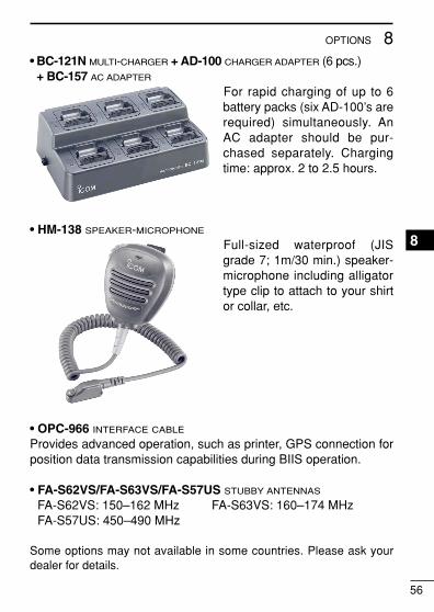
• BC-121N MULTI-CHARGER + AD-100 CHARGER ADAPTER (6 pcs.)+ BC-157 AC ADAPTER
For rapid charging of up to 6battery packs (six AD-100’s arerequired) simultaneously. AnAC adapter should be pur-chased separately. Chargingtime: approx. 2 to 2.5 hours.
• HM-138 SPEAKER-MICROPHONE
Full-sized waterproof (JISgrade 7; 1m/30 min.) speaker-microphone including alligatortype clip to attach to your shirtor collar, etc.
• OPC-966 INTERFACE CABLE
Provides advanced operation, such as printer, GPS connection forposition data transmission capabilities during BIIS operation.
• FA-S62VS/FA-S63VS/FA-S57US STUBBY ANTENNAS
FA-S62VS: 150–162 MHz FA-S63VS: 160–174 MHzFA-S57US: 450–490 MHz
Some options may not available in some countries. Please ask yourdealer for details.
IC-F50_F60_MDC-2.qxd 06.11.17 4:39 PM Page 56 (1,1)

1-1-32 Kamiminami, Hirano-ku, Osaka 547-0003, Japan
A-6533H-1EX-wPrinted in Japan© 2006 Icom Inc.
Printed on recycled paper with soy ink.
IC-F50_F60_MDC-2.qxd 06.11.17 4:39 PM Page 57 (1,1)