Embed Size (px)
Citation preview
INSTRUCTION MANUAL
iM602VHF MARINE TRANSCEIVER
This device complies with Part 15 of the FCC rules. Operation is sub-ject to the following two conditions: (1) This device may not causeharmful interference, and (2) this device must accept any interferencereceived, including interference that may cause undesired operation.

FOREWORD
Thank you for purchasing this Icom product. The IC-M602 VHF MARINE TRANSCEIVER is designed and builtwith Icom’s state of the art technology and craftsman-ship. With proper care, this product should provide youwith years of trouble-free operation.
We want to take a couple of moments of your time tothank you for making the IC-M602 your radio of choice,and hope you agree with Icom’s philosophy of “tech-nology first.” Many hours of research and developmentwent into the design of your IC-M602.
D FEATURESStandard 4×8″ flush mount design
Built-in DSC meets ITU Class D requirement
Rugged waterproof construction
Large LCD with dot matrix characters
Superior receiver performance
Optional COMMANDMICTM
(2 systems are connectable)
Icom, Icom Inc. and the logo are registered trademarksof Icom Incorporated (Japan) in the United states, the UnitedKingdom, Germany, France, Spain, Russia and/or other coun-tries.
IMPORTANT
READ THIS INSTRUCTION MANUALCAREFULLY before attempting to operate the trans-ceiver.
SAVE THIS INSTRUCTION MANUAL. Thismanual contains important safety and operating in-structions for the IC-M602.
CLEAN THE TRANSCEIVER AND MICROPHONETHOROUGHLY WITH FRESH WATER after exposure towater including salt water, otherwise, the keys andswitches may become inoperable due to salt crystallization.
i
ii
IN CASE OF EMERGENCYIf your vessel requires assistance, contact other vessels andthe Coast Guard by sending a distress call on Ch 16.
Or, transmit your distress call using digital selective calling onCh 70.
USING CHANNEL 16DISTRESS CALL PROCEDURE1. “MAYDAY MAYDAY MAYDAY.”2. “THIS IS ...............” (name of vessel)3. Your call sign or other indication of the vessel (AND 9-
digit DSC ID if you have one).4. “LOCATED AT ...............” (your position)5. The nature of the distress and assistance required.6. Any other information which might facilitate the rescue.
USING DIGITAL SELECTIVE CALLING (Ch 70)
DISTRESS CALL PROCEDURE1. While lifting up the switch cover, push and hold
[DISTRESS] for 5 sec. until you hear 5 short beepschange to one long beep.
2. Wait for an acknowledgment from a coast station.•Channel 16 is automatically selected.
3. Push and hold [PTT], then transmit the appropriateinformation as at above.
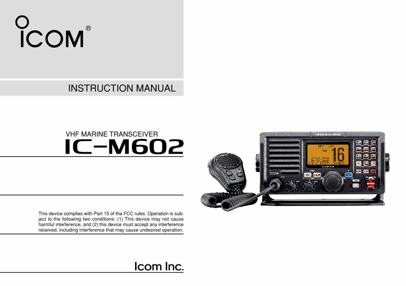
WARNING STICKER
NOTEA WARNING STICKER is supplied with the transceiver.To comply with FCC regulations, this sticker must be affixed insuch a location as to be readily seen from the operating con-trols of the radio as in the diagram below. Make sure the cho-sen location is clean and dry before applying the sticker. (p. 48)
EXAMPLE
iii
Icom requires the radio operator to meet theFCC Requirements for Radio Frequency Expo-sure. An omnidirectional antenna with gain notgreater than 9 dBi must be mounted a minimumof 5 meters (measured from the lowest point of
the antenna) vertically above the main deck and all possiblepersonnel. This is the minimum safe separation distance esti-mated to meet all RF exposure compliance requirements. This5 meter distance is based on the FCC Safe Maximum Per-missible Exposure (MPE) distance of 3 meters added to theheight of an adult (2 meters) and is appropriate for all vessels.
For watercraft without suitable structures, the antenna mustbe mounted so as to maintain a minimum of 1 meter verticallybetween the antenna, (measured from the lowest point of theantenna), to the heads of all persons AND all persons muststay outside of the 3 meter MPE radius.
Do not transmit with radio and antenna when persons arewithin the MPE radius of the antenna, unless such persons(such as driver or radio operator) are shielded from antennafield by a grounded metallic barrier. The MPE Radius is theminimum distance from the antenna axis that person shouldmaintain in order to avoid RF exposure higher than the allow-able MPE level set by FCC.
FAILURE TO OBSERVE THESE LIMITS MAY ALLOWTHOSE WITHIN THE MPE RADIUS TO EXPERIENCE RFRADIATION ABSORPTION WHICH EXCEEDS THE FCCMAXIMUM PERMISSIBLE EXPOSURE (MPE) LIMIT.IT IS THE RESPONSIBILITY OF THE RADIO OPERATORTO ENSURE THAT THE MAXIMUM PERMISSIBLE EXPO-SURE LIMITS ARE OBSERVED AT ALL TIMES DURINGRADIO TRANSMISSION. THE RADIO OPERATOR IS TOENSURE THAT NO BYSTANDERS COME WITHIN THERADIUS OF THE MAXIMUM PERMISSIBLE EXPOSURELIMITS.
Determining MPE RadiusTHE MAXIMUM PERMISSIBLE EXPOSURE (MPE) RA-DIUS HAS BEEN ESTIMATED TO BE A RADIUS OFABOUT 3M PER OET BULLETIN 65 OF THE FCC.THIS ESTIMATE IS MADE ASSUMING THE MAXIMUMPOWER OF THE RADIO AND ANTENNAS WITH A MAXI-MUM GAIN OF 9dBi ARE USED FOR A SHIP MOUNTEDSYSTEM.
RADIO OPERATOR WARNING
W ARNING
FOREWORD ............................................. iIMPORTANT .............................................. iIN CASE OF EMERGENCY ...................... iiNOTE ........................................................ iiRADIO OPERATOR WARNING ............... iiiTABLE OF CONTENTS ........................... ivPRECAUTION .......................................... v
1 OPERATING RULES .................. 12 PANEL DESCRIPTION .......... 2–7
Panel description ............................ 2 Function display .............................. 6 Microphone (HM-136) ..................... 7
3 BASIC OPERATION ............ 8–13 Channel selection ........................... 8 Receiving and transmitting ........... 10 Call channel programming ............ 11 Channel comments ....................... 11 Optional voice scrambler operation ... 13
4 DUALWATCH/TRI-WATCH ... 14–15 Description .................................... 14 Operation ...................................... 15
5 SCAN OPERATIONS ......... 16–17 Scan types .................................... 16 Setting tag channels ..................... 17 Starting a scan .............................. 17
6 DSC OPERATION .............. 18–39 MMSI code programming ............. 18
Position and time programming .... 18 Position indication ......................... 19 Distress call .................................. 20 Transmitting DSC calls ................. 22 Setting the distress information .... 30 DSC individual ID ......................... 31 Receiving DSC calls ..................... 34 DSC set mode .............................. 36 Received messages ..................... 38
7 OTHER FUNCTIONS .......... 40–46 Intercom operation ........................ 40 Hailer operation ............................ 41 Automatic fog horn ........................ 42 Microphone lock function .............. 43
8 SET MODE ........................ 44–47 Set mode programming ................ 44 Set mode items ............................. 45
9 CONNECTIONS ANDMAINTENANCE ................. 48–53 Supplied accessories .................... 48 Antenna ........................................ 48 Fuse replacement ......................... 48 Cleaning ....................................... 48 Connections .................................. 49 Mounting the transceiver .............. 50 Optional unit installation ............... 52 Dimensions ................................... 53
10 TROUBLESHOOTING .............. 54
11 CHANNEL LIST ........................ 5512 SPECIFICATIONS AND
OPTIONS ........................... 56–57 Specifications ............................... 56 Options ......................................... 57
13 HM-127 REMOTE-CONTROLMICROPHONE ................... 58–70 Panel description .......................... 58 Function display ............................ 60 HM-127 supplied accessories ...... 61 Installation .................................... 62 Channel selection ......................... 64 Receiving and transmitting ........... 65 RF attenuator function .................. 65 Lock functions ............................... 66 Display backlighting ...................... 66 Monitor function ............................ 66 Call channel programming ............ 67 Optional voice scrambler operation ... 67 Starting a scan .............................. 68 Setting tag channels ..................... 68 Dualwatch/Tri-watch operation ..... 68 Set mode programming ................ 69 Intercom operation ........................ 70 Channel comments ....................... 70
TEMPLATE
iv
TABLE OF CONTENTS 12345678910111213
v
RWARNING! NEVER connect the transceiver to an ACoutlet. This may pose a fire hazard or result in an electricshock.
CAUTION: Changes or modifications to this device, not ex-pressly approved by Icom Inc., could void your authority tooperate this device under FCC regulations.
NEVER connect the transceiver to a power source of morethan 16 V DC or use reverse polarity. This will ruin the trans-ceiver.
NEVER cut the DC power cable between the DC plug andfuse holder. If an incorrect connection is made after cutting,the transceiver may be damaged.
NEVER place the transceiver where normal operation of thevessel may be hindered or where it could cause bodily injury.
KEEP the transceiver at least 3.3 ft (1 m) away from theship’s navigation compass.
DO NOT use or place the transceiver in areas with temper-atures below –4°F (–20°C) or above +140°F (+60°C) or, inareas subject to direct sunlight, such as the dashboard.
AVOID the use of chemical agents such as benzine or al-cohol when cleaning, as they may damage the transceiversurfaces.
BE CAREFUL! The transceiver rear panel will becomehot when operating continuously for long periods.
Place the transceiver in a secure place to avoid inadvertentuse by children.
BE CAREFUL! The transceiver and optional HM-127 em-ploy waterproof construction, which corresponds to JIS wa-terproof specification, Grade 7 (1 m/30 min.). However, oncethe transceiver or microphone has been dropped, water-proofing cannot be guaranteed due to the fact that the casemay be cracked, or the waterproof seal damaged, etc.
EXPLICIT DEFINITIONS
WORD DEFINITION
RRWARNINGPersonal injury, fire hazard or electricshock may occur.
CAUTION Equipment damage may occur.
NOTEIf disregarded, inconvenience only. Norisk or personal injury, fire or electricshock.
PRECAUTION
1
1OPERATING RULES
DDPRIORITIES•Read all rules and regulations pertaining to priorities andkeep an up-to-date copy handy. Safety and distress callstake priority over all others.
•You must monitor Channel 16 when you are not operatingon another channel.
•False or fraudulent distress signals are prohibited and pun-ishable by law.
DDPRIVACY• Information overheard but not intended for you cannot law-fully be used in any way.
• Indecent or profane language is prohibited.
DDRADIO LICENSES(1) SHIP STATION LICENSEYou must have a current radio station license before using thetransceiver. It is unlawful to operate a ship station which is notlicensed.
Inquire through your dealer or the appropriate governmentagency for a Ship-Radiotelephone license application. Thisgovernment-issued license states the call sign which is yourcraft’s identification for radio purposes.
(2) OPERATOR’S LICENSEA Restricted Radiotelephone Operator Permit is the licensemost often held by small vessel radio operators when a radiois not required for safety purposes.
The Restricted Radiotelephone Operator Permit must beposted or kept with the operator. Only a licensed radio opera-tor may operate a transceiver.
However, non-licensed individuals may talk over a transceiverif a licensed operator starts, supervises, ends the call andmakes the necessary log entries.
Keep a copy of the current government rules and regulationshandy.
Radio license for boaters (U.S.A. only)The Telecommunications Act of 1996 permits recreationalboaters to have and use a VHF marine radio, EPIRB, andmarine radar without having an FCC ship station license.Boaters traveling on international voyages, having an HFsingle sideband radiotelephone or marine satellite terminal,or required to carry a marine radio under any other regula-tion must still carry an FCC ship station license. For furtherinformation, see the FCC Ship Radio Stations Fact Sheet.
1
PANEL DESCRIPTION
2
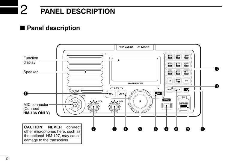
2 Panel description
WATERPROOF
VOL
iM602VHF MARINE
MIC
U/I/C 9
H/L CH/WX 16
SQLDISTRESS
Speaker
MIC connector
Functiondisplay
q
w e r t y u oi !0
!1
!2
(Connect HM-136 ONLY)
CAUTION: NEVER connect other microphones here, such as the optional HM-127, may cause damage to the transceiver.
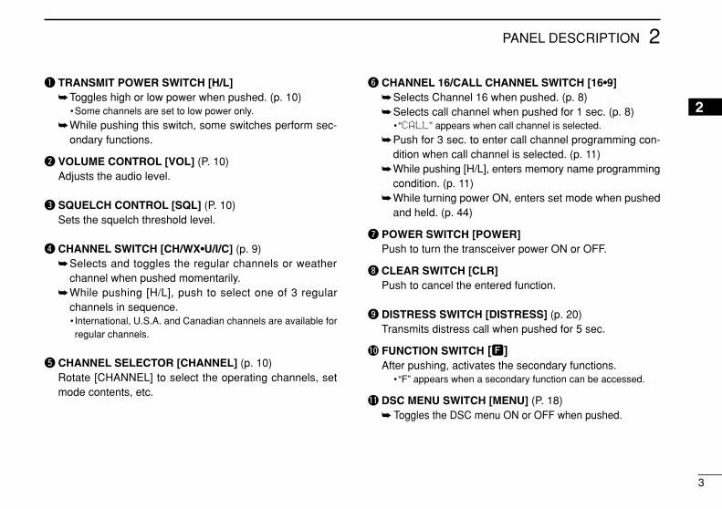
q TRANSMIT POWER SWITCH [H/L]Toggles high or low power when pushed. (p. 10)
•Some channels are set to low power only.
While pushing this switch, some switches perform sec-ondary functions.
w VOLUME CONTROL [VOL] (P. 10)Adjusts the audio level.
e SQUELCH CONTROL [SQL] (P. 10)Sets the squelch threshold level.
r CHANNEL SWITCH [CH/WX•U/I/C] (p. 9)Selects and toggles the regular channels or weather
channel when pushed momentarily.While pushing [H/L], push to select one of 3 regular
channels in sequence.• International, U.S.A. and Canadian channels are available forregular channels.
t CHANNEL SELECTOR [CHANNEL] (p. 10)Rotate [CHANNEL] to select the operating channels, setmode contents, etc.
y CHANNEL 16/CALL CHANNEL SWITCH [16•9]Selects Channel 16 when pushed. (p. 8)Selects call channel when pushed for 1 sec. (p. 8)
• “CALL” appears when call channel is selected.
Push for 3 sec. to enter call channel programming con-dition when call channel is selected. (p. 11)
While pushing [H/L], enters memory name programmingcondition. (p. 11)
While turning power ON, enters set mode when pushedand held. (p. 44)
u POWER SWITCH [POWER]Push to turn the transceiver power ON or OFF.
i CLEAR SWITCH [CLR]Push to cancel the entered function.
o DISTRESS SWITCH [DISTRESS] (p. 20)Transmits distress call when pushed for 5 sec.
!0 FUNCTION SWITCH [F]After pushing, activates the secondary functions.
• “F” appears when a secondary function can be accessed.
!1 DSC MENU SWITCH [MENU] (P. 18) Toggles the DSC menu ON or OFF when pushed.
PANEL DESCRIPTION
3
2
2

4
2 PANEL DESCRIPTION
!2 KEYPAD Inputs the numeral “1” for channel numberinput, etc.
Inputs “1,” “Q,” “Z,” “q,” “z” or space for channelcomment input.
After pushing [F], turns the dualwatch functionON or OFF. (p. 15)
Inputs the numeral “2” for channel numberinput, etc.
Inputs “2,” “A,” “B,” “C” “a,” “b” or “c” for chan-nel comment input.
After pushing [F], turns the tri-watch functionON or OFF. (p. 15)
Inputs the numeral “3” for channel numberinput, etc.
Inputs “3,” “D,” “E,” “F,” “d,” “e” or “f” for channelcomment input.
After pushing [F], push this switch and rotate[CHANNEL] to adjust the brightness of theLCD and switch backlight.
Inputs the numeral “4” for channel numberinput, etc.
Inputs “4,” “G,” “H,” “I,” “g,” “h” or “i” for channelcomment input.
After pushing [F], starts or stops the scanfunction. (p. 17)
5
2PANEL DESCRIPTION
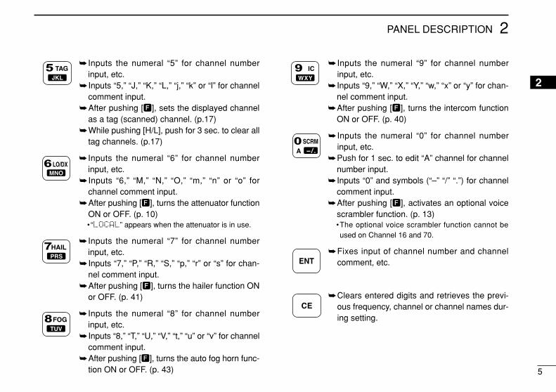
Inputs the numeral “5” for channel numberinput, etc.
Inputs “5,” “J,” “K,” “L,” “j,” “k” or “l” for channelcomment input.
After pushing [F], sets the displayed channelas a tag (scanned) channel. (p.17)
While pushing [H/L], push for 3 sec. to clear alltag channels. (p.17)
Inputs the numeral “6” for channel numberinput, etc.
Inputs “6,” “M,” “N,” “O,” “m,” “n” or “o” forchannel comment input.
After pushing [F], turns the attenuator functionON or OFF. (p. 10)•“LOCAL” appears when the attenuator is in use.
Inputs the numeral “7” for channel numberinput, etc.
Inputs “7,” “P,” “R,” “S,” “p,” “r” or “s” for chan-nel comment input.
After pushing [F], turns the hailer function ONor OFF. (p. 41)
Inputs the numeral “8” for channel numberinput, etc.
Inputs “8,” “T,” “U,” “V,” “t,” “u” or “v” for channelcomment input.
After pushing [F], turns the auto fog horn func-tion ON or OFF. (p. 43)
Inputs the numeral “9” for channel numberinput, etc.
Inputs “9,” “W,” “X,” “Y,” “w,” “x” or “y” for chan-nel comment input.
After pushing [F], turns the intercom functionON or OFF. (p. 40)
Inputs the numeral “0” for channel numberinput, etc.
Push for 1 sec. to edit “A” channel for channelnumber input.
Inputs “0” and symbols (“–” “/” “.”) for channelcomment input.
After pushing [F], activates an optional voicescrambler function. (p. 13)•The optional voice scrambler function cannot beused on Channel 16 and 70.
Fixes input of channel number and channelcomment, etc.
Clears entered digits and retrieves the previ-ous frequency, channel or channel names dur-ing setting.
2
Function display
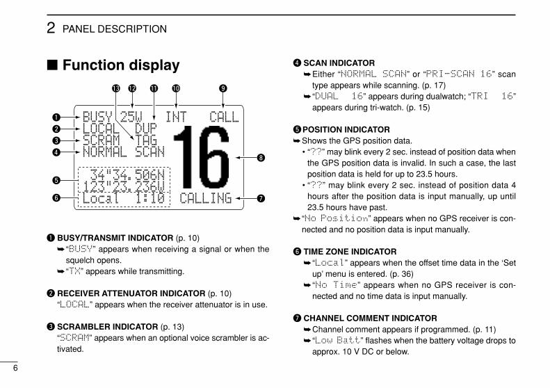
q BUSY/TRANSMIT INDICATOR (p. 10) “BUSY” appears when receiving a signal or when the
squelch opens. “TX” appears while transmitting.
w RECEIVER ATTENUATOR INDICATOR (p. 10)“LOCAL” appears when the receiver attenuator is in use.
e SCRAMBLER INDICATOR (p. 13)“SCRAM” appears when an optional voice scrambler is ac-tivated.
r SCAN INDICATOREither “NORMAL SCAN” or “PRI-SCAN 16” scan
type appears while scanning. (p. 17) “DUAL 16” appears during dualwatch; “TRI 16”
appears during tri-watch. (p. 15)
tPOSITION INDICATORShows the GPS position data.
• “??” may blink every 2 sec. instead of position data whenthe GPS position data is invalid. In such a case, the lastposition data is held for up to 23.5 hours.
• “??” may blink every 2 sec. instead of position data 4hours after the position data is input manually, up until23.5 hours have past.
“No Position” appears when no GPS receiver is con-nected and no position data is input manually.
y TIME ZONE INDICATOR “Local” appears when the offset time data in the ‘Set
up’ menu is entered. (p. 36) “No Time” appears when no GPS receiver is con-
nected and no time data is input manually.
u CHANNEL COMMENT INDICATORChannel comment appears if programmed. (p. 11) “Low Batt” flashes when the battery voltage drops to
approx. 10 V DC or below.
BUSY-25W---INT---CALLLOCAL--DUPSCRAM--TAGNORMAL-SCAN
-34"34.506N123"23.236WLocal--1:10--CALLING
w
q
e
t
y
r
!2!3 !1 !0 o
i
u
PANEL DESCRIPTION
6
2

7
2PANEL DESCRIPTION
Microphone (HM-136)
q PTT SWITCH [PTT] (p. 10)Push and hold to transmit; release to receive.
w CHANNEL UP/DOWN SWITCHES [YY]/[ZZ] (P. 10)Push either switch to change the operating channel, setmode contents, etc.
e CHANNEL 16/CALL CHANNEL SWITCH [16/9]Push to select Channel 16; push for 1 sec. to Channel 9.
(p. 8)While pushing [16/9], turn power ON to toggle the lock
function ON or OFF. (p. 43)
Speaker
Microphone
w
q
e16/9
i CHANNEL NUMBER READOUT Indicates the selected operating channel number.
“A” appears when a simplex channel is selected. (p. 9)“b” appears when a receive only channel for a Canadianchannel group is selected.
“F” appears when [F] switch is pushed.
o CALL CHANNEL INDICATOR (p. 8)“CALL” appears when the call channel is selected.
!0 CHANNEL GROUP INDICATOR (p. 9)Indicates whether an International “INT,” U.S.A. “USA,”Canadian “CAN” or weather “WX” channel is selected.
!1 DUPLEX INDICATOR (p. 9)Appears when a duplex channel is selected.
!2 POWER INDICATOR (p. 10) “25W” appears when high power is selected. “1W” appears when low power is selected.
!3 TAG CHANNEL INDICATOR (p. 17)Appears when a tag channel is selected.
2
8
3 BASIC OPERATION
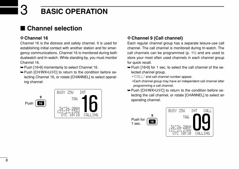
Channel selectionDDChannel 16Channel 16 is the distress and safety channel. It is used forestablishing initial contact with another station and for emer-gency communications. Channel 16 is monitored during bothdualwatch and tri-watch. While standing by, you must monitorChannel 16.Push [16•9] momentarily to select Channel 16.Push [CH/WX•U/I/C] to return to the condition before se-
lecting Channel 16, or rotate [CHANNEL] to select operat-ing channel.
DDChannel 9 (Call channel)Each regular channel group has a separate leisure-use callchannel. The call channel is monitored during tri-watch. Thecall channels can be programmed (p. 11) and are used tostore your most often used channels in each channel groupfor quick recall.Push [16•9] for 1 sec. to select the call channel of the se-
lected channel group.• “CALL” and call channel number appear. •Each channel group may have an independent call channel afterprogramming a call channel.
Push [CH/WX•U/I/C] to return to the condition before se-lecting the call channel, or rotate [CHANNEL] to select anoperating channel.
Push for1 sec.
9
16
BUSY-25W---INT---CALLLOCAL--DUPSCRAM--TAGNORMAL-SCAN
-34"34.206N123"23.236W--UTC-10:10--CALLING
Push
9
16
BUSY-25W---INT---CALLLOCAL--DUPSCRAM--TAGNORMAL-SCAN
-34"34.206N123"23.236W--UTC-10:10--CALLING
3BASIC OPERATION
9
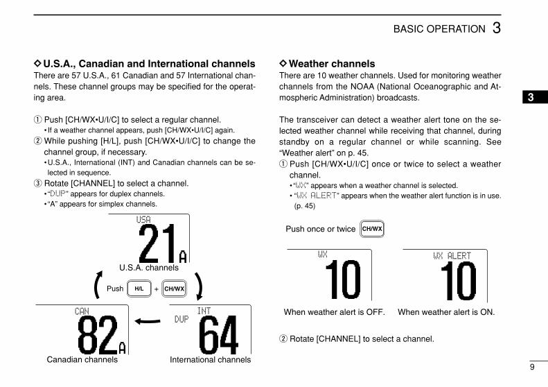
DDU.S.A., Canadian and International channelsThere are 57 U.S.A., 61 Canadian and 57 International chan-nels. These channel groups may be specified for the operat-ing area.
q Push [CH/WX•U/I/C] to select a regular channel.• If a weather channel appears, push [CH/WX•U/I/C] again.
w While pushing [H/L], push [CH/WX•U/I/C] to change thechannel group, if necessary.•U.S.A., International (INT) and Canadian channels can be se-lected in sequence.
e Rotate [CHANNEL] to select a channel.• “DUP” appears for duplex channels.• “A” appears for simplex channels.
DDWeather channelsThere are 10 weather channels. Used for monitoring weatherchannels from the NOAA (National Oceanographic and At-mospheric Administration) broadcasts.
The transceiver can detect a weather alert tone on the se-lected weather channel while receiving that channel, duringstandby on a regular channel or while scanning. See“Weather alert” on p. 45.q Push [CH/WX•U/I/C] once or twice to select a weather
channel.• “WX” appears when a weather channel is selected.• “WX ALERT” appears when the weather alert function is in use.
(p. 45)
w Rotate [CHANNEL] to select a channel.
Push once or twice
When weather alert is OFF. When weather alert is ON.
WX ALERTWX
CH/WX
Push +
U.S.A. channels
H/L CH/WX
Canadian channels
CAN
International channels
INTDUP
USA
3

Receiving and transmittingCAUTION: Transmitting without an antenna may dam-age the transceiver.
q Push [POWER] to turn power ON.w Set the audio and squelch levels.
Rotate [SQL] fully counterclockwise in advance.Rotate [VOL] to adjust the audio output level.Rotate [SQL] clockwise until the noise disappears.
e To change the channel group, push [CH/WX•U/I/C] whilepushing [H/L]. (p. 9)
r Rotate [CHANNEL] or push [Y]/[Z] on the microphone toselect the desired channel.•When receiving a signal, “BUSY” appears and audio is emittedfrom the speaker.
•Further adjustment of [VOL] may be necessary at this point.•Use the optional voice scrambler function for privacy. (p. 13)
t Push [F], then push [6 LO/DX] to turn the receive attenua-tor function ON or OFF if necessary.• “LOCAL” appears when the receive attenuator is in use.
y Push [H/L] to select the output power if necessary.• “25W” or “1W” appears when high or low power is selected, re-spectively.
•Choose low power to conserve power, choose high power forlonger distance communications.
•Some channels are for low power only.
u Push and hold [PTT] to transmit, then speak into the mi-crophone.• “TX” appears.•Channel 70 cannot be used for transmission.
Simplex channels, 3, 21, 23, 61, 64, 81, 82 and 83 CAN-NOT be lawfully used by the general public in U.S.A. wa-ters.
i Release [PTT] to receive.
IMPORTANT: To maximize the readability of your trans-mitted signal, pause a few sec. after pushing [PTT], holdthe microphone 1 to 2 inches (2.5 to 5 cm) from yourmouth and speak at a normal voice level.
WATERPROOF
VOL
iM602VHF MARINE
MIC
U/I/C 9
SQL
16/9
w
e t
q rr
y u i
3 BASIC OPERATION
10
3BASIC OPERATION
11
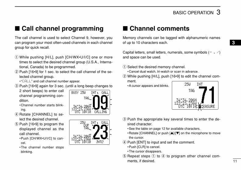
Call channel programmingThe call channel is used to select Channel 9, however, youcan program your most often-used channels in each channelgroup for quick recall.
q While pushing [H/L], push [CH/WX•U/I/C] one or moretimes to select the desired channel group (U.S.A., Interna-tional, Canada) to be programmed.
w Push [16•9] for 1 sec. to select the call channel of the se-lected channel group.• “CALL” and call channel number appear.
e Push [16•9] again for 3 sec. (until a long beep changes to2 short beeps) to enter callchannel programming con-dition.•Channel number starts blink-ing.
r Rotate [CHANNEL] to se-lect the desired channel.
t Push [16•9] to program thedisplayed channel as thecall channel.•Push [CH/WX•U/I/C] to can-cel.
•The channel number stopsblinking.
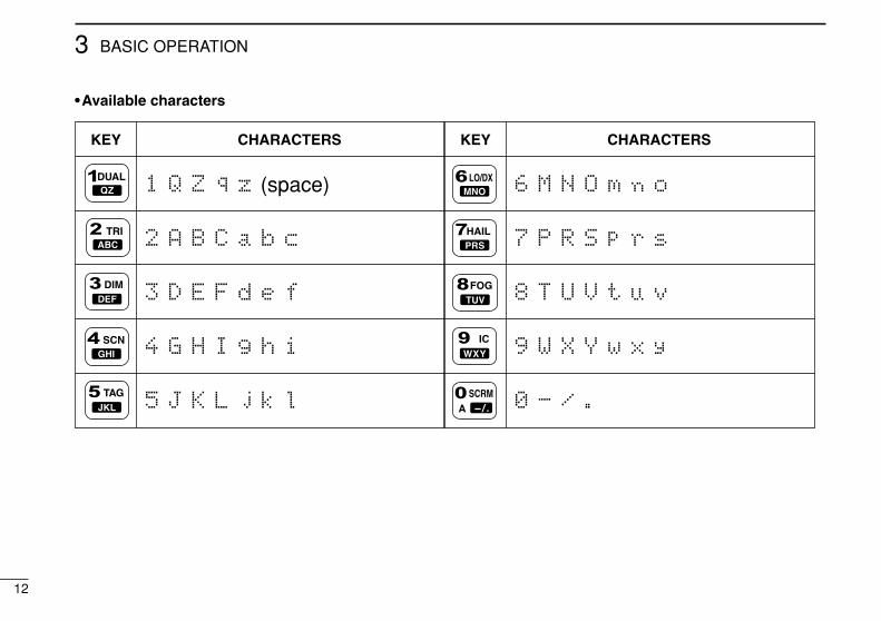
Channel commentsMemory channels can be tagged with alphanumeric namesof up to 10 characters each.
Capital letters, small letters, numerals, some symbols (- ./)and space can be used.
q Select the desired memory channel.•Cancel dual watch, tri-watch or scan in advance.
w While pushing [H/L], push [16•9] to edit the channel com-ment.•A cursor appears and blinks.
e Push the appropriate key several times to enter the de-sired character.•See the table on page 12 for available characters.•Rotate [CHANNEL] or push [Y]/[Z] on the microphone to movethe cursor.
r Push [ENT] to input and set the comment.•Push [CLR] to cancel.•The cursor disappears.
t Repeat steps q to r to program other channel com-ments, if desired.
BUSYBUSY-25W25W------INTINT------CALLCALLLOCAL--DUPLOCAL--DUPSCRAMSCRAM----TAGTAGNORMAL-SCANNORMAL-SCAN
-34"34.206N34"34.206N123"23.236W123"23.236W----UTCUTC-10:1010:10----CALLINGCALLING
BUSYBUSY-25W25W------INTINT------CALLCALLLOCAL--LOCAL--DUPDUPSCRAMSCRAM----TAGTAGNORMAL-SCANNORMAL-SCAN
-34"34.206N34"34.206N123"23.236W123"23.236W----UTCUTC-10:1010:10------INTLINTL
BUSY-BUSY-25W25W------INTINT------CALLCALLLOCAL--LOCAL--DUPDUPSCRAMSCRAM----TAGTAGNORMAL-SCANNORMAL-SCAN
-34"34.206N34"34.206N123"23.236W123"23.236W----UTCUTC-10:1010:10-PLEASURELEASURE
3
12
3 BASIC OPERATION
KEY CHARACTERS KEY CHARACTERS
1
2
3
4
5
Q
A
D
G
J
Z
B
E
H
K
q
C
F
I
L
z (space)
a
d
g
j
b
e
h
k
c
f
i
l
6
7
8
9
0
M
P
T
W
-
N
R
U
X
/
O
S
V
Y
.
m n o
p
t
w
r
u
x
s
v
y
•Available characters
13
3BASIC OPERATION
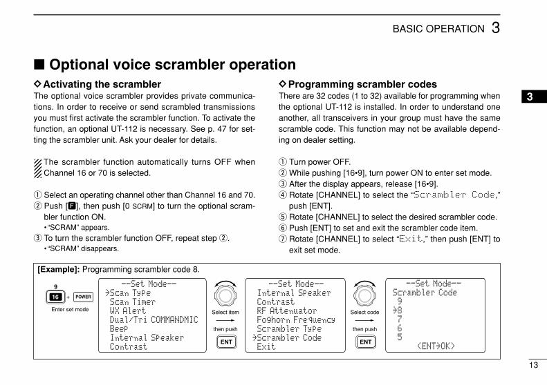
Optional voice scrambler operationDDActivating the scramblerThe optional voice scrambler provides private communica-tions. In order to receive or send scrambled transmissionsyou must first activate the scrambler function. To activate thefunction, an optional UT-112 is necessary. See p. 47 for set-ting the scrambler unit. Ask your dealer for details.
The scrambler function automatically turns OFF whenChannel 16 or 70 is selected.
q Select an operating channel other than Channel 16 and 70.w Push [F], then push [0 SCRM] to turn the optional scram-
bler function ON.• “SCRAM” appears.
e To turn the scrambler function OFF, repeat step w.• “SCRAM” disappears.
DDProgramming scrambler codesThere are 32 codes (1 to 32) available for programming whenthe optional UT-112 is installed. In order to understand oneanother, all transceivers in your group must have the samescramble code. This function may not be available depend-ing on dealer setting.
q Turn power OFF.w While pushing [16•9], turn power ON to enter set mode.e After the display appears, release [16•9].r Rotate [CHANNEL] to select the “Scrambler Code,”
push [ENT].t Rotate [CHANNEL] to select the desired scrambler code.y Push [ENT] to set and exit the scrambler code item.u Rotate [CHANNEL] to select “Exit,” then push [ENT] to
exit set mode.
Enter set mode
POWER+
9
16
ENT ENT
Select item
then push
Select code
then push
Scrambler Code˘9
˘7
--Set Mode--
˘5˘6
˘8
˘<ENT˘OK>
˘Scan Type˘Scan Timer
--Set Mode--
˘Internal Speaker˘Contrast
˘Beep˘Dual/Tri COMMANDMIC˘WX Alert
˘Internal Speaker˘Contrast
--Set Mode--
˘Scrambler Code˘Exit
˘Scrambler Type˘Foghorn Frequency˘RF Attenuator
[Example]: Programming scrambler code 8.
3
14
4 DUAL WATCH/TRI-WATCH
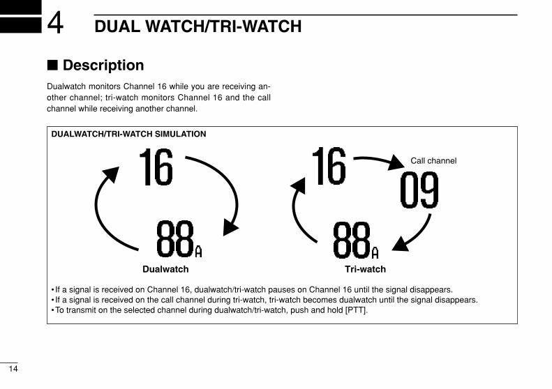
DescriptionDualwatch monitors Channel 16 while you are receiving an-other channel; tri-watch monitors Channel 16 and the callchannel while receiving another channel.
DUALWATCH/TRI-WATCH SIMULATION
• If a signal is received on Channel 16, dualwatch/tri-watch pauses on Channel 16 until the signal disappears.• If a signal is received on the call channel during tri-watch, tri-watch becomes dualwatch until the signal disappears.•To transmit on the selected channel during dualwatch/tri-watch, push and hold [PTT].
Call channel
Dualwatch Tri-watch
15
4DUAL WATCH/TRI-WATCH
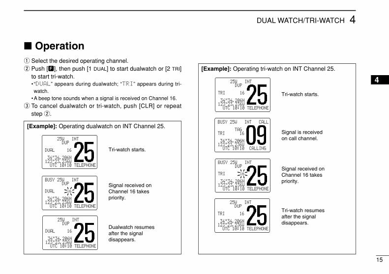
Operationq Select the desired operating channel.w Push [F], then push [1 DUAL] to start dualwatch or [2 TRI]
to start tri-watch.• “DUAL” appears during dualwatch; “TRI” appears during tri-watch.
•A beep tone sounds when a signal is received on Channel 16.
e To cancel dualwatch or tri-watch, push [CLR] or repeatstep w.
[Example]: Operating dualwatch on INT Channel 25.
[Example]: Operating tri-watch on INT Channel 25.
BUSY-25W---INT---CALLLOCAL--DUPSCRAM--TAGDUALAL-SC16
-34"34.206N123"23.236W--UTC-10:10-TELEPHONE
BUSY-25W---INT---CALLLOCAL--DUPSCRAM--TAGDUALAL-SC16
-34"34.206N123"23.236W--UTC-10:10-TELEPHONE
BUSY-25W---INT---CALLLOCAL--DUPSCRAM--TAGDUALAL-SC16
-34"34.206N123"23.236W--UTC-10:10-TELEPHONE
Tri-watch starts.
Signal received on Channel 16 takes priority.
Dualwatch resumes after the signal disappears.
BUSY-25W---INT---CALLLOCAL--DUPSCRAM--TAGTRIMAL-SC16
-34"34.206N123"23.236W--UTC-10:10-TELEPHONE
BUSY-25W---INT---CALLLOCAL--DUPSCRAM--TAGTRIMAL-SC16
-34"34.206N123"23.236W--UTC-10:10-TELEPHONE
BUSY-25W---INT---CALLLOCAL--DUPSCRAM--TAGTRIMAL-SC16
-34"34.206N123"23.236W--UTC-10:10-TELEPHONE
BUSY-25W---INT---CALLLOCAL--DUPSCRAM--TAGTRIMAL-SC16
-34"34.206N123"23.236W--UTC-10:10--CALLING
Tri-watch starts.
Signal is received on call channel.
Signal received on Channel 16 takes priority.
Tri-watch resumes after the signal disappears.
4
5 SCAN OPERATIONS
16
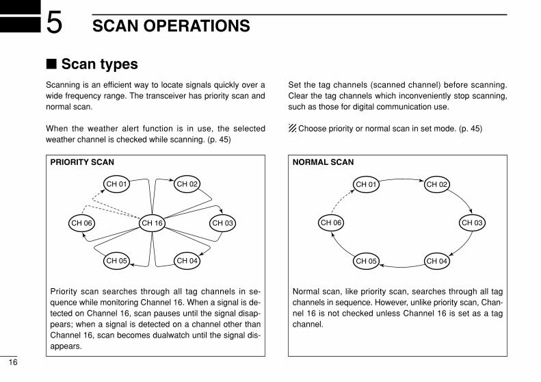
Scan typesScanning is an efficient way to locate signals quickly over awide frequency range. The transceiver has priority scan andnormal scan.
When the weather alert function is in use, the selectedweather channel is checked while scanning. (p. 45)
Set the tag channels (scanned channel) before scanning.Clear the tag channels which inconveniently stop scanning,such as those for digital communication use.
Choose priority or normal scan in set mode. (p. 45)
NORMAL SCAN
Normal scan, like priority scan, searches through all tagchannels in sequence. However, unlike priority scan, Chan-nel 16 is not checked unless Channel 16 is set as a tagchannel.
CH 01 CH 02
CH 06
CH 05 CH 04
CH 03
PRIORITY SCAN
Priority scan searches through all tag channels in se-quence while monitoring Channel 16. When a signal is de-tected on Channel 16, scan pauses until the signal disap-pears; when a signal is detected on a channel other thanChannel 16, scan becomes dualwatch until the signal dis-appears.
CH 06
CH 01
CH 16
CH 02
CH 05 CH 04
CH 03
5SCAN OPERATION
17
Push
SCNGHI
then
Scan starts. When a signal is received
BUSY-25W---INT---CALLLOCAL--DUPSCRAM--TAGNORMAL-SCAN
-34"34.206N123"23.236W--UTC-10:10---INTL-
BUSY-25W---INT---CALLLOCAL--DUPSCRAM--TAGNORMAL-SCAN
-34"34.206N123"23.236W--UTC-10:10---INTL-
4
BUSY-25W---INT---CALLLOCAL--DUPSCRAM--TAGNORMAL-SCAN
-34"34.206N123"23.236W--UTC-10:10---INTL-
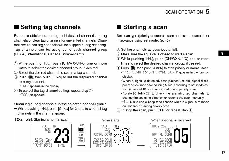
[Example]: Starting a normal scan.
Setting tag channelsFor more efficient scanning, add desired channels as tagchannels or clear tag channels for unwanted channels. Chan-nels set as non-tag channels will be skipped during scanning.Tag channels can be assigned to each channel group(U.S.A., International, Canada) independently.
q While pushing [H/L], push [CH/WX•U/I/C] one or moretimes to select the desired channel group, if desired.
w Select the desired channel to set as a tag channel.e Push [F], then push [5 TAG] to set the displayed channel
as a tag channel.• “TAG” appears in the display.
r To cancel the tag channel setting, repeat step e.• “TAG” disappears.
•Clearing all tag channels in the selected channel groupWhile pushing [H/L], push [5 TAG] for 3 sec. to clear all tag
channels in the channel group.
Starting a scanSet scan type (priority or normal scan) and scan resume timerin advance using set mode. (p. 45)
q Set tag channels as described at left.w Make sure the squelch is closed to start a scan.e While pushing [H/L], push [CH/WX•U/I/C] one or more
times to select the desired channel group, if desired.r Push [F], then push [4 SCN] to start priority or normal scan.
• “PRI-SCAN 16” or “NORMAL SCAN” appears in the functiondisplay.
•When a signal is detected, scan pauses until the signal disap-pears or resumes after pausing 5 sec. according to set mode set-ting. (Channel 16 is still monitored during priority scan.)
•Rotate [CHANNEL] to check the scanning tag channels, tochange the scanning direction or resume the scan manually.
• “16” blinks and a beep tone sounds when a signal is receivedon Channel 16 during priority scan.
t To stop the scan, push [CLR] or repeat step r.
5

18
6 DSC OPERATION
MMSI code programmingThe 9-digit MMSI (Maritime Mobile Service Identity: DSC selfID) code can be programmed at power ON.
This code programming can be performed only twice.
q Turn power OFF.w While pushing [MENU], turn power ON to enter MMSI
code programming condition.e After the display appears, release [MENU].r Push [MENU] to enter the DSC menu.t Rotate [CHANNEL] to select “Set up,” push [ENT].y Rotate [CHANNEL] to select “MMSI check,” push [ENT].
u Edit the specific MMSI code directly with the keypad.• Rotate [CHANNEL] to move the cursor backward or forward.
i Input the 9 digit code, then push [ENT] to set the code.• Returns to the DSC set up menu.
o Rotate [CHANNEL] to select “Exit,” push [ENT].• Returns to the DSC menu.• Repeat again to return to the normal operation condition.
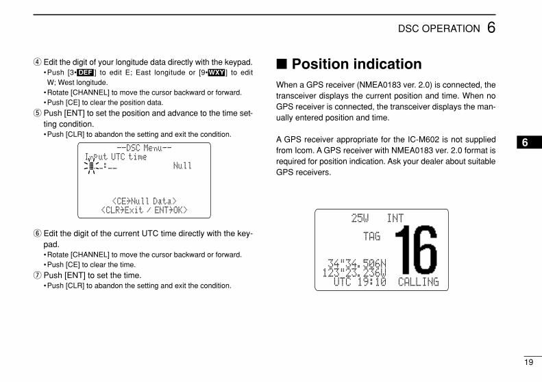
Position and time programmingA distress call should include the ship’s position and time. Ifno GPS is connected, your position and UTC (Universal TimeCoordinated) time should be input. They are included auto-matically when a GPS receiver (NMEA0183 ver. 2.0) is con-nected.
This manual programming is not available when a GPS re-ceiver (NMEA0183 ver. 2.0) is connected.
q Push [MENU] to enter the DSC menu.w Rotate [CHANNEL] to select “Position Input,” push
[ENT].
e Edit the digit of your latitude data directly with the keypad.•Push [6• ] to edit N; North latitude or [7• ] to edit S; South latitude.
•Rotate [CHANNEL] to move the cursor backward or forward.•Push [CE] to clear the position data.
PRSMNO
Input PositionLatitude
Longitude
--DSC Menu--
<CE˘Null Data>___°__.___W˘˘˘˘˘˘˘˘Null
˘L_°__.___N˘˘˘˘˘˘˘˘Null
<CLR˘Exit / ENT˘OK>
MMSI Check˘ä________________
--DSC Menu--
<CLR˘Exit / ENT˘OK>
19
6DSC OPERATION
r Edit the digit of your longitude data directly with the keypad.•Push [3• ] to edit E; East longitude or [9• ] to edit W; West longitude.
•Rotate [CHANNEL] to move the cursor backward or forward.•Push [CE] to clear the position data.
t Push [ENT] to set the position and advance to the time set-ting condition.•Push [CLR] to abandon the setting and exit the condition.
y Edit the digit of the current UTC time directly with the key-pad.•Rotate [CHANNEL] to move the cursor backward or forward.•Push [CE] to clear the time.
u Push [ENT] to set the time.•Push [CLR] to abandon the setting and exit the condition.
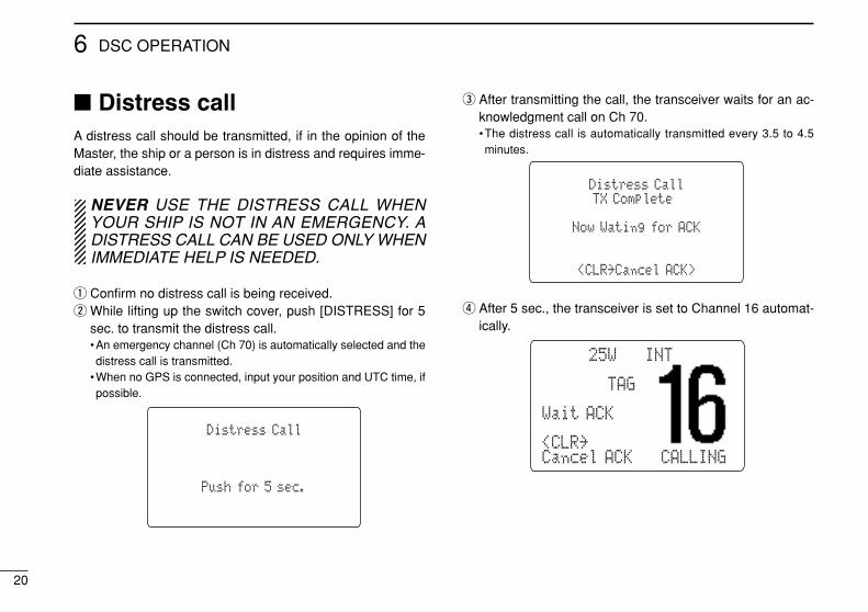
Position indicationWhen a GPS receiver (NMEA0183 ver. 2.0) is connected, thetransceiver displays the current position and time. When noGPS receiver is connected, the transceiver displays the man-ually entered position and time.
A GPS receiver appropriate for the IC-M602 is not suppliedfrom Icom. A GPS receiver with NMEA0183 ver. 2.0 format isrequired for position indication. Ask your dealer about suitableGPS receivers.
BUSY-25W---INT---CALLLOCAL--DUPSCRAM--TAGNORMAL-SCAN
-34"34.506N123"23.236W--UTC-19:10--CALLING
Input UTC time˘L__:__˘˘˘˘˘˘˘˘˘˘˘˘Null
--DSC Menu--
<CE˘Null Data><CLR˘Exit / ENT˘OK>
WXYDEF
6
20
6 DSC OPERATION
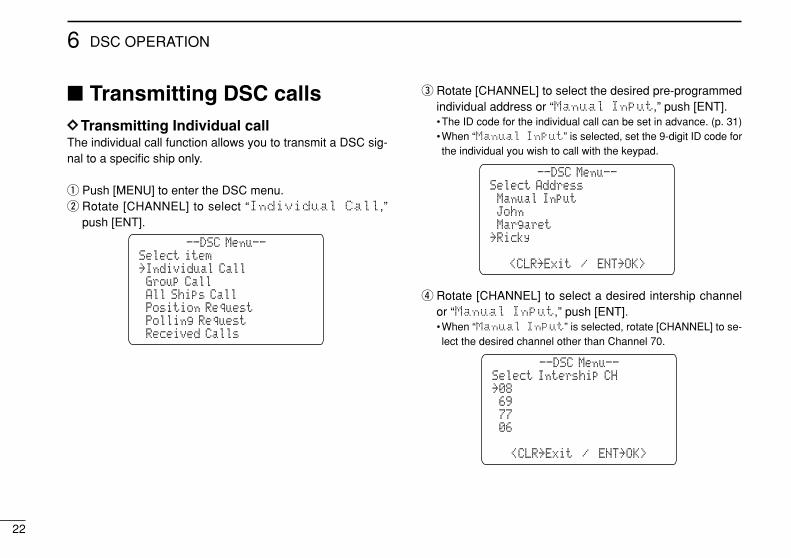
Distress callA distress call should be transmitted, if in the opinion of theMaster, the ship or a person is in distress and requires imme-diate assistance.
NEVER USE THE DISTRESS CALL WHENYOUR SHIP IS NOT IN AN EMERGENCY. ADISTRESS CALL CAN BE USED ONLY WHENIMMEDIATE HELP IS NEEDED.
q Confirm no distress call is being received.w While lifting up the switch cover, push [DISTRESS] for 5
sec. to transmit the distress call.•An emergency channel (Ch 70) is automatically selected and thedistress call is transmitted.
•When no GPS is connected, input your position and UTC time, ifpossible.
e After transmitting the call, the transceiver waits for an ac-knowledgment call on Ch 70.•The distress call is automatically transmitted every 3.5 to 4.5minutes.
r After 5 sec., the transceiver is set to Channel 16 automat-ically.
BUSY-25W---INT---CALLLOCAL--DUPSCRAM--TAGNORMAL-SCANWait ACK-34"34.506N<CLR˘Cancel ACK---CALLING
Distress CallTX Complete
Now Wating for ACK
<CLR˘Cancel ACK>
Distress Call
Push for 5 sec.

21
6DSC OPERATION
t When receiving the acknowledgment, reply using the mi-crophone.
A distress alert contains (default);•Kind of distress : Undesignated distress•Position data : GPS or manual input position data held for
23.5 hrs.
The distress call is repeated every 3.5–4.5 min., until re-ceiving an ‘acknowledgement.’
Push [DISTRESS] to transmit a renewed distress call, ifrequired.
Push [CLR] to cancel the ‘Call repeat’ mode. “??” may blink instead of position and time indications
when the GPS data is invalid, or has not been updatedafter 4 hours the position and time data input manually.
BUSY-25W---INT---CALLLOCAL--DUPSCRAM--TAGReceivedCANDistressACK<Osaka Bay>Chuck3-<CLR˘Exit>--CALLING
6
22
6 DSC OPERATION
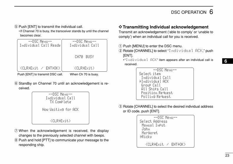
Transmitting DSC callsDDTransmitting Individual callThe individual call function allows you to transmit a DSC sig-nal to a specific ship only.
q Push [MENU] to enter the DSC menu.w Rotate [CHANNEL] to select “Individual Call,”
push [ENT].
e Rotate [CHANNEL] to select the desired pre-programmedindividual address or “Manual Input,” push [ENT].•The ID code for the individual call can be set in advance. (p. 31)•When “Manual Input” is selected, set the 9-digit ID code forthe individual you wish to call with the keypad.
r Rotate [CHANNEL] to select a desired intership channelor “Manual Input,” push [ENT].•When “Manual Input” is selected, rotate [CHANNEL] to se-lect the desired channel other than Channel 70.
Select Intership CH
<CLR˘Exit / ENT˘OK>
˘08
˘77
--DSC Menu--
˘˘06
˘69
Select Address
<CLR˘Exit / ENT˘OK>
˘Manual Input
˘Margaret
--DSC Menu--
˘Ricky
˘John
Select item
˘Received Calls
˘Individual Call
˘All Ships Call
--DSC Menu--
˘Polling Request˘Position Request
˘Group Call
23
6DSC OPERATION
t Push [ENT] to transmit the individual call.• If Channel 70 is busy, the transceiver stands by until the channelbecomes clear.
y Standby on Channel 70 until an acknowledgement is re-ceived.
u When the acknowledgement is received, the displaychanges to the previously selected channel with beeps.
i Push and hold [PTT] to communicate your message to theresponding ship.
DDTransmitting Individual acknowledgementTransmit an acknowledgement (‘able to comply’ or ‘unable tocomply’) when an individual call for you is received.
q Push [MENU] to enter the DSC menu.w Rotate [CHANNEL] to select “Individual ACK,” push
[ENT].• “Individual ACK” item appears after an individual call isreceived.
e Rotate [CHANNEL] to select the desired individual addressor ID code, push [ENT].
Select Address
<CLR˘Exit / ENT˘OK>
˘Manual Input
˘Margaret
--DSC Menu--
˘Ricky
˘John
Select item
˘Polling Request
˘Individual Call
˘Group Call
--DSC Menu--
˘Position Request˘All Ships Call
˘Individual ACK
Individual Call
<CLR˘Exit>
TX Complete
Now Waiting for ACK
--DSC Menu--
˘˘Ricky
˘Icom
Individual Call Ready
<CLR˘Exit / ENT˘OK>
--DSC Menu--Individual Call
CH70 BUSY
<CLR˘Exit>
--DSC Menu--
Push [ENT] to transmit DSC call. When Ch 70 is busy.
6
24
6 DSC OPERATION
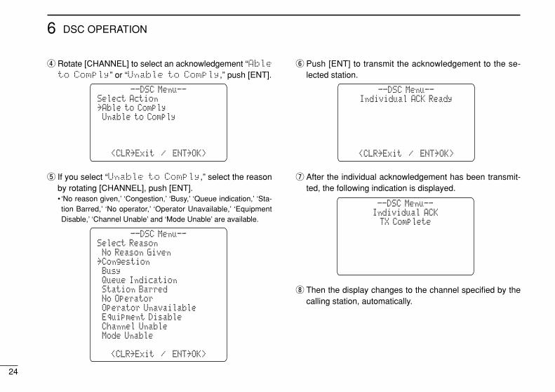
r Rotate [CHANNEL] to select an acknowledgement “Ableto Comply” or “Unable to Comply,” push [ENT].
t If you select “Unable to Comply,” select the reasonby rotating [CHANNEL], push [ENT].• ‘No reason given,’ ‘Congestion,’ ‘Busy,’ ‘Queue indication,’ ‘Sta-tion Barred,’ ‘No operator,’ ‘Operator Unavailable,’ ‘EquipmentDisable,’ ‘Channel Unable’ and ‘Mode Unable’ are available.
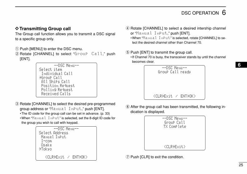
y Push [ENT] to transmit the acknowledgement to the se-lected station.
u After the individual acknowledgement has been transmit-ted, the following indication is displayed.
i Then the display changes to the channel specified by thecalling station, automatically.
Individual ACKTX Complete
--DSC Menu--
Individual ACK Ready
<CLR˘Exit / ENT˘OK>
--DSC Menu--
Select Reason˘No Reason Given
˘Busy
--DSC Menu--
˘
˘Queue Indication˘Station Barred
˘Channel Unable
˘No Operator˘Operator Unavailable˘Equipment Disable
<CLR˘Exit / ENT˘OK>
˘Mode Unable˘Equipment Disable
˘Congestion
Select Action
<CLR˘Exit / ENT˘OK>
˘Able to Comply
˘77
--DSC Menu--
˘
˘06
˘Unable to Comply
25
6DSC OPERATION
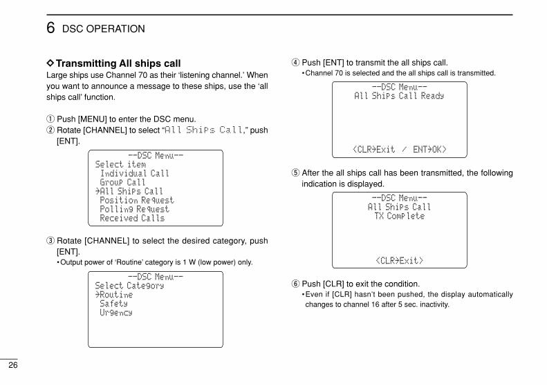
DDTransmitting Group callThe Group call function allows you to transmit a DSC signalto a specific group only.
q Push [MENU] to enter the DSC menu.w Rotate [CHANNEL] to select “Group Call,” push
[ENT].
e Rotate [CHANNEL] to select the desired pre-programmedgroup address or “Manual Input,” push [ENT].•The ID code for the group call can be set in advance. (p. 33)•When “Manual Input” is selected, set the 8-digit ID code forthe group you wish to call with keypad.
r Rotate [CHANNEL] to select a desired intership channelor “Manual Input,” push [ENT].•When “Manual Input” is selected, rotate [CHANNEL] to se-lect the desired channel other than Channel 70.
t Push [ENT] to transmit the group call.• If Channel 70 is busy, the transceiver stands by until the channelbecomes clear.
y After the group call has been transmitted, the following in-dication is displayed.
u Push [CLR] to exit the condition.
Group CallTX Complete
<CLR˘Exit>
--DSC Menu--
Group Call ready
<CLR˘Exit / ENT˘OK>
--DSC Menu--
Select Address
<CLR˘Exit / ENT˘OK>
˘Manual Input
˘Osaka
--DSC Menu--
˘˘Tokyo
˘I-com
Select item
˘Received Calls
˘Individual Call
˘All Ships Call
--DSC Menu--
˘Polling Request˘Position Request
˘Group Call
6
26
6 DSC OPERATION
DDTransmitting All ships callLarge ships use Channel 70 as their ‘listening channel.’ Whenyou want to announce a message to these ships, use the ‘allships call’ function.
q Push [MENU] to enter the DSC menu.w Rotate [CHANNEL] to select “All Ships Call,” push
[ENT].
e Rotate [CHANNEL] to select the desired category, push[ENT].•Output power of ‘Routine’ category is 1 W (low power) only.
r Push [ENT] to transmit the all ships call.•Channel 70 is selected and the all ships call is transmitted.
t After the all ships call has been transmitted, the followingindication is displayed.
y Push [CLR] to exit the condition.•Even if [CLR] hasn’t been pushed, the display automaticallychanges to channel 16 after 5 sec. inactivity.
All Ships CallTX Complete
<CLR˘Exit>
--DSC Menu--
All Ships Call Ready
<CLR˘Exit / ENT˘OK>
--DSC Menu--
Select Category
˘Received Calls
˘Routine
˘Urgency
--DSC Menu--
˘Polling Request˘Position Request
˘Safety
Select item
˘Received Calls
˘Individual Call
˘All Ships Call
--DSC Menu--
˘Polling Request˘Position Request
˘Group Call
27
6DSC OPERATION
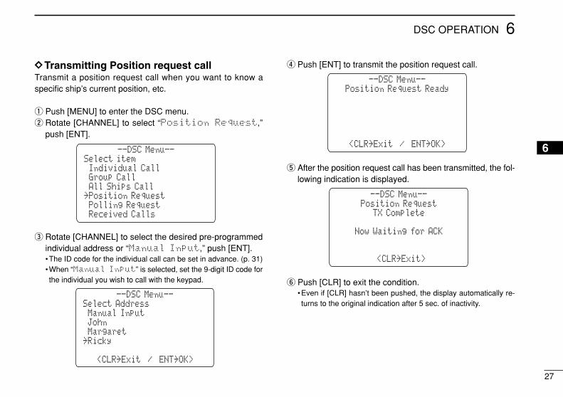
DDTransmitting Position request callTransmit a position request call when you want to know aspecific ship’s current position, etc.
q Push [MENU] to enter the DSC menu.w Rotate [CHANNEL] to select “Position Request,”
push [ENT].
e Rotate [CHANNEL] to select the desired pre-programmedindividual address or “Manual Input,” push [ENT].•The ID code for the individual call can be set in advance. (p. 31)•When “Manual Input” is selected, set the 9-digit ID code forthe individual you wish to call with the keypad.
r Push [ENT] to transmit the position request call.
t After the position request call has been transmitted, the fol-lowing indication is displayed.
y Push [CLR] to exit the condition.•Even if [CLR] hasn’t been pushed, the display automatically re-turns to the original indication after 5 sec. of inactivity.
Position RequestTX Complete
--DSC Menu--
˘<CLR˘Exit>
Now Waiting for ACK
Position Request Ready
<CLR˘Exit / ENT˘OK>
--DSC Menu--
Select Address
<CLR˘Exit / ENT˘OK>
˘Manual Input
˘Margaret
--DSC Menu--
˘Ricky
˘John
Select item
˘Received Calls
˘Individual Call
˘All Ships Call
--DSC Menu--
˘Polling Request˘Position Request
˘Group Call
6
28
6 DSC OPERATION
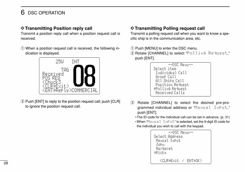
DDTransmitting Position reply callTransmit a position reply call when a position request call isreceived.
q When a position request call is received, the following in-dication is displayed.
w Push [ENT] to reply to the position request call; push [CLR]to ignore the position request call.
DDTransmitting Polling request callTransmit a polling request call when you want to know a spe-cific ship is in the communication area, etc.
q Push [MENU] to enter the DSC menu.w Rotate [CHANNEL] to select “Polling Request,”
push [ENT].
e Rotate [CHANNEL] to select the desired pre-pro-grammed individual address or “Manual Input,”push [ENT].
•The ID code for the individual call can be set in advance. (p. 31)•When “Manual Input” is selected, set the 9-digit ID code forthe individual you wish to call with the keypad.
Select Address
<CLR˘Exit / ENT˘OK>
˘Manual Input
˘Margaret
--DSC Menu--
˘Ricky
˘John
Select item
˘Received Calls
˘Individual Call
˘All Ships Call
--DSC Menu--
˘Polling Request˘Position Request
˘Group Call
BUSY-25W---INT---CALLLOCAL--DUPSCRAM--TAGReceivedCANPOS REQ<Chuck3<CLR˘Exit><ENT˘Reply>COMMERCIAL

29
6DSC OPERATION
r Push [ENT] to transmit the polling request call.
t After the polling request call has been transmitted, the fol-lowing indication is displayed
y Push [CLR] to exit the condition.•Even if [CLR] hasn’t been pushed, the display automatically re-turns to the original indication after 5 sec. of inactivity.
DDTransmitting Polling reply callTransmit a polling reply call when a polling request call is re-ceived.
q When a polling request call is received, the following indi-cation is displayed.
w Push [ENT] to reply to the polling request call; push [CLR]to ignore the polling request call.
BUSY-25W---INT---CALLLOCAL--DUPSCRAM--TAGReceivedCANPOLL REQ<Chuck3<CLR˘Exit><ENT˘Reply>COMMERCIAL
˘
Polling RequestTX Complete
--DSC Menu--
<CLR˘Exit>
Now Waiting for ACK
Polling Request Ready
˘<CLR˘Exit / ENT˘OK>
--DSC Menu--
6

30
6 DSC OPERATION
Setting the distress informationThe nature of the distress call should be included in the dis-tress call.
q Push [MENU] to enter the DSC menu.w Rotate [CHANNEL] to select “Distress Setting,”
push [ENT].
e Rotate [CHANNEL] to select the nature of the distress,push [ENT].• ‘Undesignated,’ ‘Explosion,’ ‘Flooding,’ ‘Collision,’ ‘Grounding,’‘Capsizing,’ ‘Sinking,’ ‘Adrift (Disable adrift),’ ‘Abandoning (Aban-doning ship),’ ‘Piracy (Piracy attack)’ and ‘MOB (Man overboard)’are available.
r The position information appears. Set the current position,then push [ENT].•Edit the digit of your position data directly with the keypad.•Push [6• ] to edit N; North latitude or [7• ] to edit S; South latitude.
•Push [3• ] to edit E; East longitude or [9• ] to edit W; West longitude.
•Rotate [CHANNEL] to move the cursor backward or forward.•Push [CE] to clear the position data.
WXYDEF
PRSMNO
Select Nature˘Undesignated
˘Flooding
--DSC Menu--
˘
˘Collision˘Grounding
˘Abandoning
˘Capsizing˘Sinking˘Adrift
<CLR˘Exit / ENT˘OK>
˘Piracy˘MOB˘-----
˘Explosion
Select item
˘Exit
˘Position Request
˘Received Calls
--DSC Menu--
˘Set up˘Distress Setting
˘Polling Request

31
6DSC OPERATION
t The time information appears. Set the current UTC time,push [ENT].•Edit the digit of the current UTC time directly with the keypad.•Push [CLR] to abandon the setting and exit the condition to se-lecting the nature menu.
•Rotate [CHANNEL] to move the cursor backward or forward.•Push [CE] to clear the time.•The selected nature of the distress is stored for 10 minutes.
y Push [DISTRESS] for 5 sec. to transmit the distress call.
DSC individual IDA total of 100 DSC address IDs can be programmed andnamed with up to 10 characters.
DDProgramming Address IDq Push [MENU] to enter the DSC menu.w Rotate [CHANNEL] to select “Set up,” push [ENT].
e Rotate [CHANNEL] to select “Add: INDV ID,” push[ENT].
Set up
˘MMSI Check
˘Add:INDV ID
˘DEL:INDV ID
--DSC Menu--
˘Offset time˘DEL:Group ID
˘Add:Group ID
Select item
˘Exit
˘Position Request
˘Received Calls
--DSC Menu--
˘Set up˘Distress Setting
˘Polling Request
Input UTC time˘L__:__˘˘˘˘˘˘˘˘˘˘˘˘Null
--DSC Menu--
<CE˘Null Data><CLR˘Exit / ENT˘OK>
Input PositionLatitude
Longitude
--DSC Menu--
<CE˘Null Data>___°__.___W˘˘˘˘˘˘˘˘Null
˘L_°__.___N˘˘˘˘˘˘˘˘Null
<CLR˘Exit / ENT˘OK>
6
32
6 DSC OPERATION
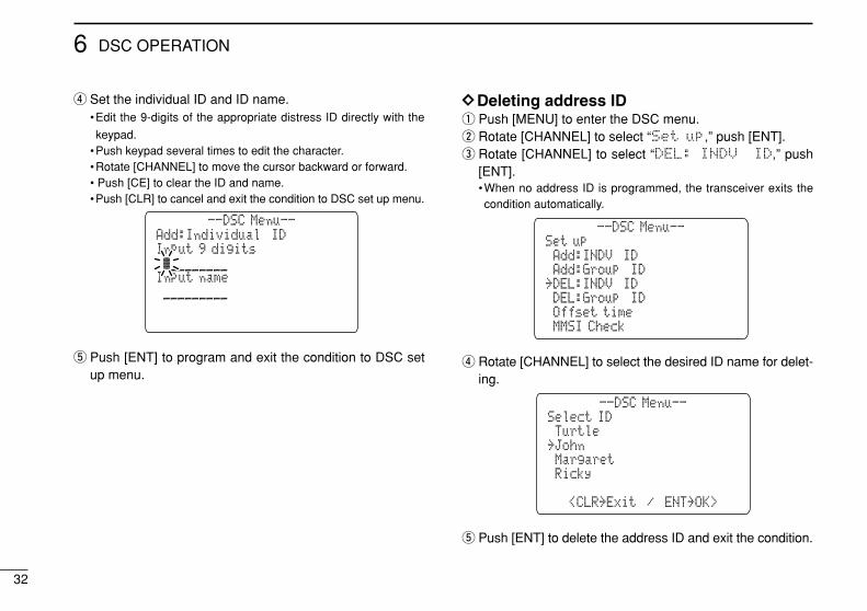
r Set the individual ID and ID name.•Edit the 9-digits of the appropriate distress ID directly with the
keypad.•Push keypad several times to edit the character.•Rotate [CHANNEL] to move the cursor backward or forward.• Push [CE] to clear the ID and name.•Push [CLR] to cancel and exit the condition to DSC set up menu.
t Push [ENT] to program and exit the condition to DSC setup menu.
DDDeleting address IDq Push [MENU] to enter the DSC menu.w Rotate [CHANNEL] to select “Set up,” push [ENT].e Rotate [CHANNEL] to select “DEL: INDV ID,” push
[ENT].•When no address ID is programmed, the transceiver exits thecondition automatically.
r Rotate [CHANNEL] to select the desired ID name for delet-ing.
t Push [ENT] to delete the address ID and exit the condition.
Select ID
<CLR˘Exit / ENT˘OK>
˘Turtle
˘Margaret
--DSC Menu--
˘˘Ricky
˘John
Set up
˘MMSI Check
˘Add:INDV ID
˘DEL:INDV ID
--DSC Menu--
˘Offset time˘DEL:Group ID
˘Add:Group ID
Add:Individual IDInput 9 digits
Input name
--DSC Menu--
˘__________________
˘ä________________
33
6DSC OPERATION
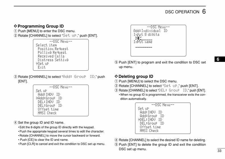
DDProgramming Group IDq Push [MENU] to enter the DSC menu.w Rotate [CHANNEL] to select “Set up,” push [ENT].
e Rotate [CHANNEL] to select “Add: Group ID,” push[ENT].
r Set the group ID and ID name.•Edit the 8-digits of the group ID directly with the keypad.•Push the appopriate keypad several times to edit the character.•Rotate [CHANNEL] to move the cursor backward or forward.• Push [CE] to clear the ID and name.•Push [CLR] to cancel and exit the condition to DSC set up menu.
t Push [ENT] to program and exit the condition to DSC setup menu.
DDDeleting group IDq Push [MENU] to select the DSC menu.w Rotate [CHANNEL] to select “Set up,” push [ENT].e Rotate [CHANNEL] to select “DEL: Group ID,” push [ENT].
•When no group ID is programmed, the transceiver exits the con-dition automatically.
r Rotate [CHANNEL] to select the desired ID name for deleting.t Push [ENT] to delete the group ID and exit the condition
DSC set up menu.
Set up
˘MMSI Check
˘Add:INDV ID
˘DEL:INDV ID
--DSC Menu--
˘Offset time˘DEL:Group ID
˘Add:Group ID
Add:Individual IDInput 8 digits
Input name
--DSC Menu--
˘__________________
˘0ä______________
Set up
˘MMSI Check
˘Add:INDV ID
˘DEL:INDV ID
--DSC Menu--
˘Offset time˘DEL:Group ID
˘Add:Group ID
Select item
˘Exit
˘Position Request
˘Received Calls
--DSC Menu--
˘Set up˘Distress Setting
˘Polling Request
6
34
6 DSC OPERATION
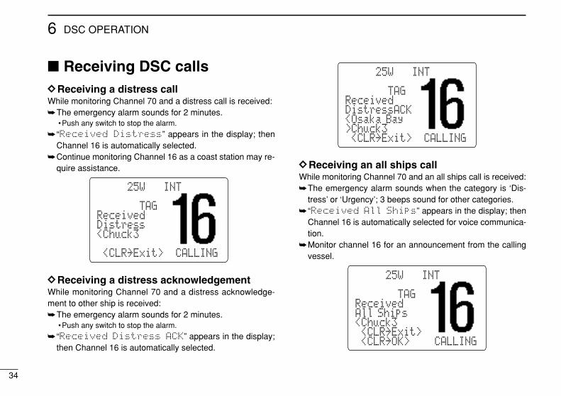
Receiving DSC callsDDReceiving a distress callWhile monitoring Channel 70 and a distress call is received:The emergency alarm sounds for 2 minutes.
•Push any switch to stop the alarm.
“Received Distress” appears in the display; thenChannel 16 is automatically selected.
Continue monitoring Channel 16 as a coast station may re-quire assistance.
DDReceiving a distress acknowledgementWhile monitoring Channel 70 and a distress acknowledge-ment to other ship is received:The emergency alarm sounds for 2 minutes.
•Push any switch to stop the alarm.
“Received Distress ACK” appears in the display;then Channel 16 is automatically selected.
DDReceiving an all ships callWhile monitoring Channel 70 and an all ships call is received:The emergency alarm sounds when the category is ‘Dis-
tress’ or ‘Urgency’; 3 beeps sound for other categories. “Received All Ships” appears in the display; then
Channel 16 is automatically selected for voice communica-tion.
Monitor channel 16 for an announcement from the callingvessel.
BUSY-25W---INT---CALLLOCAL--DUPSCRAM--TAGReceivedCANAll Ships<Chuck3><CLR˘Exit>-<CLR˘OK> --CALLING
BUSY-25W---INT---CALLLOCAL--DUPSCRAM--TAGReceivedCANDistressACK<Osaka Bay>Chuck3-<CLR˘Exit>--CALLING
BUSY-25W---INT---CALLLOCAL--DUPSCRAM--TAGReceivedCANDistress<Chuck3
-<CLR˘Exit>--CALLING
35
6DSC OPERATION
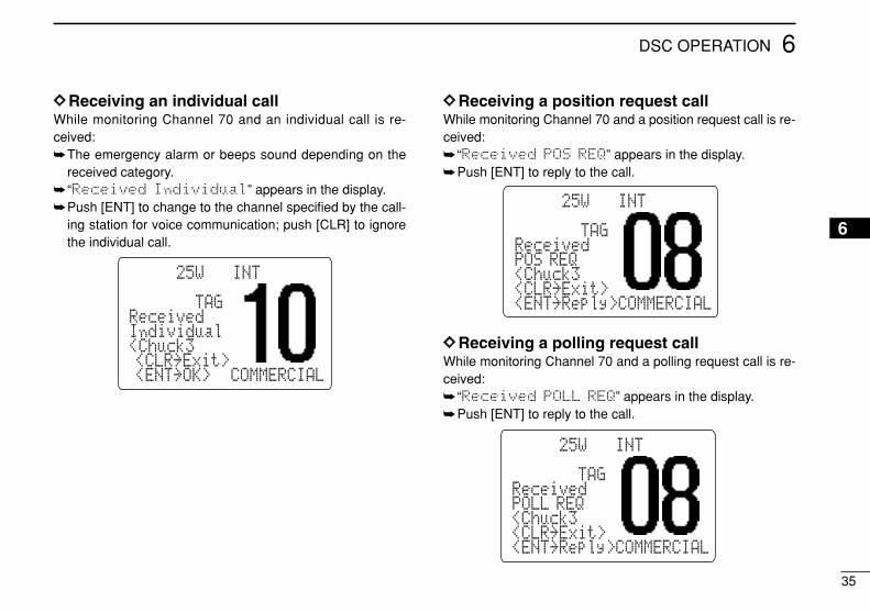
DDReceiving an individual callWhile monitoring Channel 70 and an individual call is re-ceived:The emergency alarm or beeps sound depending on the
received category. “Received Individual” appears in the display.Push [ENT] to change to the channel specified by the call-
ing station for voice communication; push [CLR] to ignorethe individual call.
DDReceiving a position request callWhile monitoring Channel 70 and a position request call is re-ceived: “Received POS REQ” appears in the display.Push [ENT] to reply to the call.
DDReceiving a polling request callWhile monitoring Channel 70 and a polling request call is re-ceived: “Received POLL REQ” appears in the display.Push [ENT] to reply to the call.
BUSY-25W---INT---CALLLOCAL--DUPSCRAM--TAGReceivedCANPOLL REQ<Chuck3<CLR˘Exit><ENT˘Reply>COMMERCIAL
BUSY-25W---INT---CALLLOCAL--DUPSCRAM--TAGReceivedCANPOS REQ<Chuck3<CLR˘Exit><ENT˘Reply>COMMERCIAL
BUSY-25W---INT---CALLLOCAL--DUPSCRAM--TAGReceivedCANIndividual<Chuck3 <CLR˘Exit> <ENT˘OK> COMMERCIAL
6
36
6 DSC OPERATION
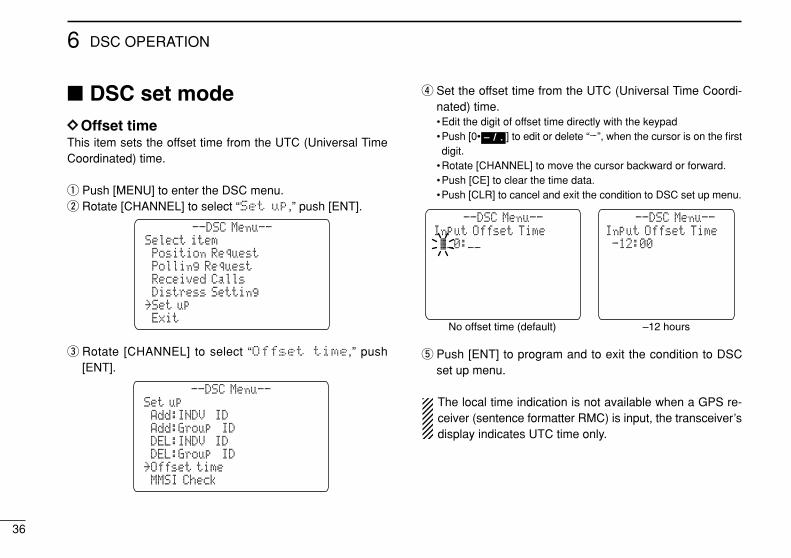
DSC set modeDDOffset timeThis item sets the offset time from the UTC (Universal TimeCoordinated) time.
q Push [MENU] to enter the DSC menu.w Rotate [CHANNEL] to select “Set up,” push [ENT].
e Rotate [CHANNEL] to select “Offset time,” push[ENT].
r Set the offset time from the UTC (Universal Time Coordi-nated) time.•Edit the digit of offset time directly with the keypad•Push [0• ] to edit or delete “-”, when the cursor is on the firstdigit.
•Rotate [CHANNEL] to move the cursor backward or forward.•Push [CE] to clear the time data.•Push [CLR] to cancel and exit the condition to DSC set up menu.
t Push [ENT] to program and to exit the condition to DSCset up menu.
The local time indication is not available when a GPS re-ceiver (sentence formatter RMC) is input, the transceiver’sdisplay indicates UTC time only.
Input Offset Time--DSC Menu--
No offset time (default) –12 hours
L_0:__Input Offset Time
--DSC Menu--
-12:00
– / .
Set up
˘MMSI Check
˘Add:INDV ID
˘DEL:INDV ID
--DSC Menu--
˘Offset time˘DEL:Group ID
˘Add:Group ID
Select item
˘Exit
˘Position Request
˘Received Calls
--DSC Menu--
˘Set up˘Distress Setting
˘Polling Request
37
6DSC OPERATION
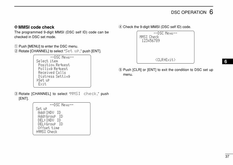
DDMMSI code checkThe programmed 9-digit MMSI (DSC self ID) code can bechecked in DSC set mode.
q Push [MENU] to enter the DSC menu.w Rotate [CHANNEL] to select “Set up,” push [ENT].
e Rotate [CHANNEL] to select “MMSI check,” push[ENT].
r Check the 9-digit MMSI (DSC self ID) code.
t Push [CLR] or [ENT] to exit the condition to DSC set upmenu.
MMSI Check˘123456789
--DSC Menu--
<CLR˘Exit>
Set up
˘MMSI Check
˘Add:INDV ID
˘DEL:INDV ID
--DSC Menu--
˘Offset time˘DEL:Group ID
˘Add:Group ID
Select item
˘Exit
˘Position Request
˘Received Calls
--DSC Menu--
˘Set up˘Distress Setting
˘Polling Request
6
38
6 DSC OPERATION
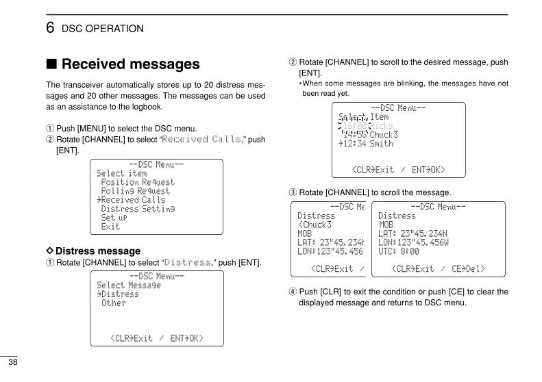
Received messagesThe transceiver automatically stores up to 20 distress mes-sages and 20 other messages. The messages can be usedas an assistance to the logbook.
q Push [MENU] to select the DSC menu.w Rotate [CHANNEL] to select “Received Calls,” push
[ENT].
DDDistress messageq Rotate [CHANNEL] to select “Distress,” push [ENT].
w Rotate [CHANNEL] to scroll to the desired message, push[ENT].•When some messages are blinking, the messages have notbeen read yet.
e Rotate [CHANNEL] to scroll the message.
r Push [CLR] to exit the condition or push [CE] to clear thedisplayed message and returns to DSC menu.
Distress<Chuck3
LAT: 23"45.234N
--DSC Menu--
LON:123"45.456W
MOB
<CLR˘Exit / CE˘Del>
Distress--DSC Menu--
UTC: 8:00
LAT: 23"45.234NLON:123"45.456W
MOB
<CLR˘Exit / CE˘Del>
--DSC Menu--
<CLR˘Exit / ENT˘OK>
Select Item˘16:00 Ricky˘14:56 Chuck3˘12:34 Smith
--DSC Menu--
<CLR˘Exit / ENT˘OK>
Select Message˘Distress˘Other
Select item
˘Exit
˘Position Request
˘Received Calls
--DSC Menu--
˘Set up˘Distress Setting
˘Polling Request
39
6DSC OPERATION
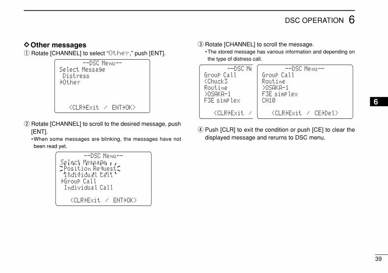
DDOther messagesq Rotate [CHANNEL] to select “Other,” push [ENT].
w Rotate [CHANNEL] to scroll to the desired message, push[ENT].•When some messages are blinking, the messages have notbeen read yet.
e Rotate [CHANNEL] to scroll the message.•The stored message has various information and depending onthe type of distress call.
r Push [CLR] to exit the condition or push [CE] to clear thedisplayed message and rerurns to DSC menu.
Group Call<Chuck3
>OSAKA-1
--DSC Menu--
F3E simplex
Routine
<CLR˘Exit / CE˘Del>
Group Call--DSC Menu--
CH10
>OSAKA-1F3E simplex
Routine
<CLR˘Exit / CE˘Del>
--DSC Menu--
<CLR˘Exit / ENT˘OK>
Select Message˘Position Request˘Individual Call˘Group Call˘Individual Call
--DSC Menu--
<CLR˘Exit / ENT˘OK>
Select Message˘Distress˘Other
6
40
7 OTHER FUNCTIONS
Intercom operationThe optional intercom function allows you to talk to the deckfrom the cabin. The optional HM-127 REMOTE-CONTROL MI-
CROPHONE is required for intercom operation.
Connect an optional HM-127 as described on p. 62.•Transmitting is impossible during intercom operation.•The received signal is muted during intercom operation.
q Push [F], then push [9 IC] to enter intercom mode.•The HM-127 power is automatically turned ON, even if the poweris OFF.
w Push and hold [9 IC] again to call up.•The transceiver and microphone emit call beeps.
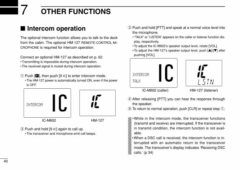
e Push and hold [PTT] and speak at a normal voice level intothe microphone.• “TALK” or “LISTEN” appears on the caller or listener function dis-play, respectively.
•To adjust the IC-M602’s speaker output level, rotate [VOL].•To adjust the HM-127’s speaker output level, push [Y]/[Z] afterpushing [VOL].
r After releasing [PTT] you can hear the response throughthe speaker.
t To return to normal operation, push [CLR] or repeat step q.
•While in the intercom mode, the transceiver functions(transmit and receive) are interrupted. If the transceiver isin transmit condition, the intercom function is not avail-able.
•When a DSC call is received, the intercom function is in-terrupted with an automatic return to the transceivermode. The transceiver’s display indicates ‘Receiving DSCcalls.’ (p 34)
INT
BUSY-25W---INT---CALLLOCAL--DUPSCRAM--TAGNORMAL-SCANINTERCOM-34"34.206NTALK123"23.236W--UTC-10:10COMMERCIAL
IC-M602 (caller) HM-127 (listener)
INT
BUSY-25W---INT---CALLLOCAL--DUPSCRAM--TAGNORMAL-SCANINTERCOM-34"34.206N123"23.236W--UTC-10:10COMMERCIAL
IC-M602 HM-127
41
7OTHER FUNCTIONS
Hailer operationThe IC-M602 has a 2-way hailer function for voice amplifica-tion and reception over a loudspeaker, making it unnecessaryto leave the bridge to hear a hailing party.
Connect an external hailer speaker as described on p. 49.•Transmitting is not possible during hailer operation.•The received signal is muted during hailer operation.
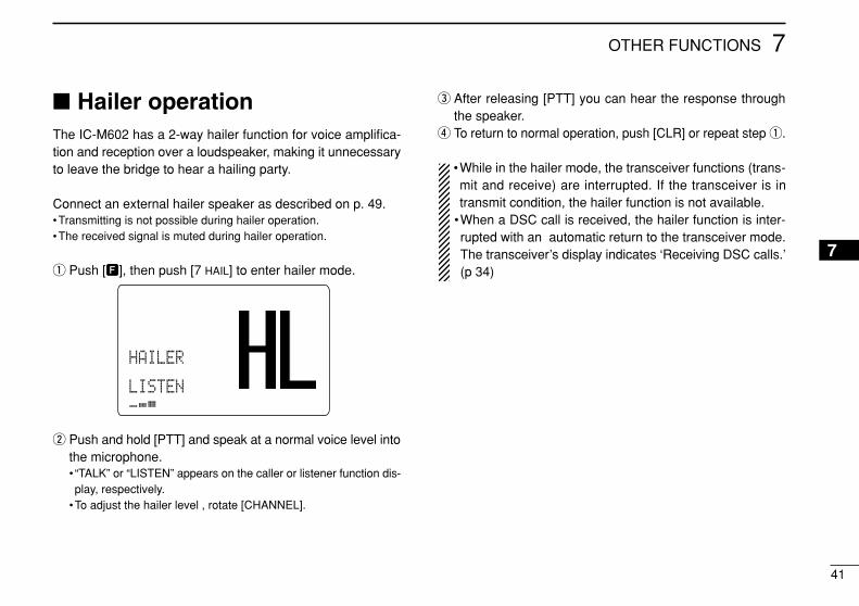
q Push [F], then push [7 HAIL] to enter hailer mode.
w Push and hold [PTT] and speak at a normal voice level intothe microphone.• “TALK” or “LISTEN” appears on the caller or listener function dis-play, respectively.
•To adjust the hailer level , rotate [CHANNEL].
e After releasing [PTT] you can hear the response throughthe speaker.
r To return to normal operation, push [CLR] or repeat step q.
•While in the hailer mode, the transceiver functions (trans-mit and receive) are interrupted. If the transceiver is intransmit condition, the hailer function is not available.
•When a DSC call is received, the hailer function is inter-rupted with an automatic return to the transceiver mode.The transceiver’s display indicates ‘Receiving DSC calls.’(p 34)
BUSY-25W---INT---CALLLOCAL--DUPSCRAM--TAGNORMAL-SCANHAILER-34"34.506NLISTEN.236W___cal--1:10--CALLING____
7
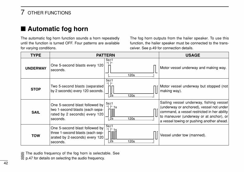
Automatic fog hornThe automatic fog horn function sounds a horn repeatedlyuntil the function is turned OFF. Four patterns are availablefor varying conditions.
The fog horn outputs from the hailer speaker. To use thisfunction, the hailer speaker must be connected to the trans-ceiver. See p.49 for connection details.
TYPE PATTERN USAGE
UNDERWAY
STOP
SAIL
TOW
42
7 OTHER FUNCTIONS
The audio frequency of the fog horn is selectable. Seep.47 for details on selecting the audio frequency.
One 5-second blasts every 120seconds.
Two 5-second blasts (separatedby 2 seconds) every 120 seconds.
One 5-second blast followed bytwo 1-second blasts (each sepa-rated by 2 seconds) every 120seconds.
One 5-second blast followed bythree 1-second blasts (each sep-arated by 2-seconds) every 120seconds.
Motor vessel underway and making way.
Motor vessel underway but stopped (notmaking way).
Sailing vessel underway, fishing vessel(underway or anchored), vessel not undercommand, a vessel restricted in her abilityto maneuver (underway or at anchor), ora vessel towing or pushing another ahead.
Vessel under tow (manned).
5s±1
120s
5s±1
2s
1s
120s
5s±1
2s
1s
120s
5s±1
2s 120s

43
7OTHER FUNCTIONS
q Push [F], then push [8 FOG] to enter auto fog horn mode.w Rotate [CHANNEL] to select the desired fog horn pattern,
push [ENT].• ‘UNDERWAY,’ ‘STOP,’ ‘SAIL,’ ‘TOW’ are available. (p.42)•Even if [ENT] hasn’t been pushed, the display automaticallychanges to the next step after 5 sec. of inactivity.
e Rotate [CHANNEL] to adjust the fog horn level, push[ENT].•The fog horn level is adjustable in 7 steps.•Even if [ENT] hasn’t been pushed, the display automaticallychanges to the next step after 5 sec. of inactivity.
r To return to normal operation, repeat step q.
When a DSC call is received, the automatic fog horn func-tion is interrupted with an automatic return to the trans-ceiver mode. The transceiver’s display indicates ‘Receiving DSC calls.’ (p 34)
Microphone lock functionThe microphone lock function electrically locks the [Y]/[Z]and [16/9] switches on the supplied microphone. This pre-vents accidental channel changes and accidental function ac-cess.
While pushing [16/9] on the HM-136, turn power ON to tog-gle the lock function ON or OFF.
BUSY-25W---INT---CALLLOCAL--DUPSCRAM--TAGReceivedCANFOG HORNOUTPUTUNDERWAYE<ENT˘OK> COMMERCIAL_______
BUSY-25W---INT---CALLLOCAL--DUPSCRAM--TAGReceivedCANFOG HORNOUTPUT <CLR˘Exit>E<ENT˘OK> COMMERCIAL_______
BUSY-25W---INT---CALLLOCAL--DUPSCRAM--TAGReceivedCAN˘UNDERWAY<STOP <CLR˘Exit> <ENT˘OK> COMMERCIAL
7
8 SET MODE
44
Beep tone
Beep
Scan type
Scan type
Weather alert
WX Alert
Scan resume timer
Scan timer
Attenuation level
RFAttenuator
Scrambler code
Scramblercode
Scrambler type
Scramblertype
Dual/tri-watch of COMMANDMIC
Dual/Tri COMMANDMIC
LCD contrast
Contrast
Rotate
or
[CHANNEL] Push when using HM-127
˘Scan Type˘Scan Timer
˘Dual/Tri COMMANDMIC
--Set Mode--
˘Internal Speaker˘Beep
˘WX Alert
˘Contrast˘RF Attenuator
˘Scrambler Type
˘Exit˘Scrambler Code
˘Foghorn Frequency
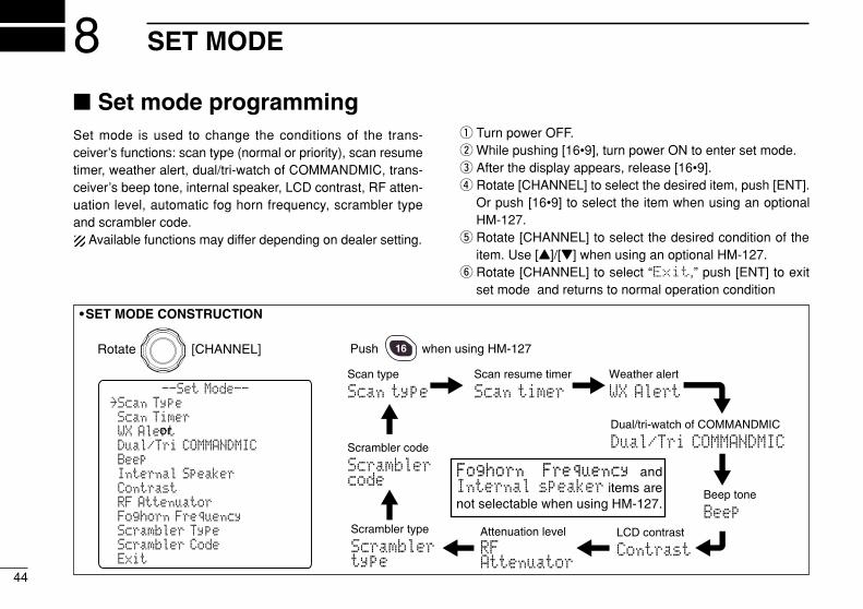
Foghorn FrequencyFoghorn Frequency and Internal speaker items are not selectable when using HM-127.
Set mode programmingSet mode is used to change the conditions of the trans-ceiver’s functions: scan type (normal or priority), scan resumetimer, weather alert, dual/tri-watch of COMMANDMIC, trans-ceiver’s beep tone, internal speaker, LCD contrast, RF atten-uation level, automatic fog horn frequency, scrambler typeand scrambler code.
Available functions may differ depending on dealer setting.
q Turn power OFF.w While pushing [16•9], turn power ON to enter set mode.e After the display appears, release [16•9].r Rotate [CHANNEL] to select the desired item, push [ENT].
Or push [16•9] to select the item when using an optionalHM-127.
t Rotate [CHANNEL] to select the desired condition of theitem. Use [Y]/[Z] when using an optional HM-127.
y Rotate [CHANNEL] to select “Exit,” push [ENT] to exitset mode and returns to normal operation condition
•SET MODE CONSTRUCTION
8SET MODE
45
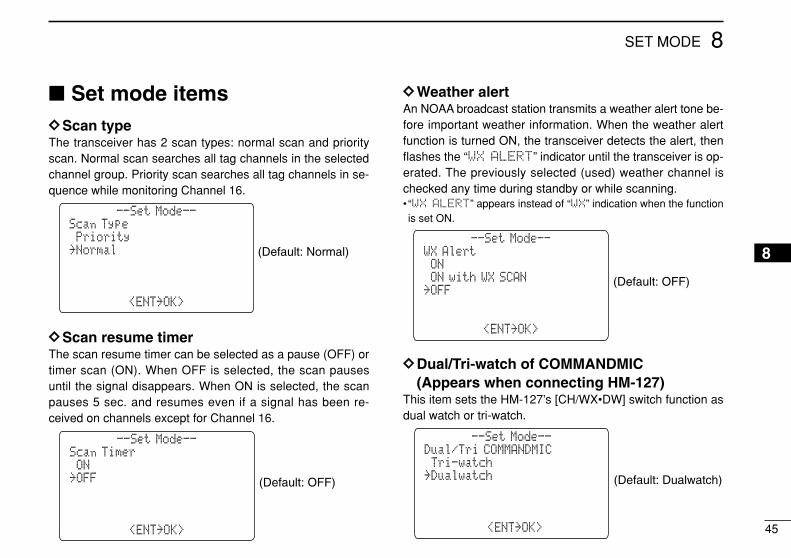
Set mode itemsDDScan typeThe transceiver has 2 scan types: normal scan and priorityscan. Normal scan searches all tag channels in the selectedchannel group. Priority scan searches all tag channels in se-quence while monitoring Channel 16.
DDScan resume timerThe scan resume timer can be selected as a pause (OFF) ortimer scan (ON). When OFF is selected, the scan pausesuntil the signal disappears. When ON is selected, the scanpauses 5 sec. and resumes even if a signal has been re-ceived on channels except for Channel 16.
DDWeather alertAn NOAA broadcast station transmits a weather alert tone be-fore important weather information. When the weather alertfunction is turned ON, the transceiver detects the alert, thenflashes the “WX ALERT” indicator until the transceiver is op-erated. The previously selected (used) weather channel ischecked any time during standby or while scanning.• “WX ALERT” appears instead of “WX” indication when the functionis set ON.
DDDual/Tri-watch of COMMANDMIC(Appears when connecting HM-127)
This item sets the HM-127’s [CH/WX•DW] switch function asdual watch or tri-watch.
Dual/Tri COMMANDMIC˘Tri-watch
˘OFF
--Set Mode--
˘Polling Request˘Position Request
˘Dualwatch
˘<ENT˘OK>
(Default: Dualwatch)
WX Alert˘ON
˘OFF
--Set Mode--
˘Polling Request˘Position Request
˘ON with WX SCAN
<ENT˘OK>
(Default: OFF)
Scan Timer˘ON
˘All Ships Call
--Set Mode--
˘Polling Request˘Position Request
˘OFF
<ENT˘OK>
(Default: OFF)
Scan Type˘Priority
˘All Ships Call
--Set Mode--
˘Polling Request˘Position Request
˘Normal
<ENT˘OK>
(Default: Normal) 8
46
8 SET MODE
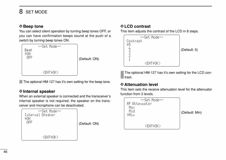
DDBeep toneYou can select silent operation by turning beep tones OFF, oryou can have confirmation beeps sound at the push of aswitch by turning beep tones ON.
The optional HM-127 has it’s own setting for the beep tone.
DD Internal speakerWhen an external speaker is connected and the transceiver’sinternal speaker is not required, the speaker on the trans-ceiver and microphone can be deactivated.
DDLCD contrastThis item adjusts the contrast of the LCD in 8 steps.
The optional HM-127 has it’s own setting for the LCD con-trast.
DDAttenuation levelThis item sets the receive attenuation level for the attenuatorfunction from 3 levels.
RF Attenuator˘Max
˘Min
--Set Mode--
˘1˘2
˘Mid
˘<ENT˘OK>
(Default: Min)
Contrast˘5
˘3
--Set Mode--
˘1˘2
˘4
˘<ENT˘OK>
(Default: 5)
Internal Speaker˘ON
˘OFF
--Set Mode--
˘Polling Request˘Position Request
˘OFF
˘<ENT˘OK>
(Default: ON)
Beep˘ON
˘OFF
--Set Mode--
˘Polling Request˘Position Request
˘OFF
˘<ENT˘OK>
(Default: ON)
47
8SET MODE
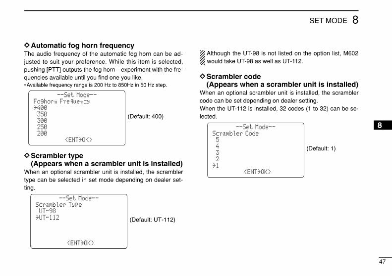
DDAutomatic fog horn frequencyThe audio frequency of the automatic fog horn can be ad-justed to suit your preference. While this item is selected,pushing [PTT] outputs the fog horn—experiment with the fre-quencies available until you find one you like.•Available frequency range is 200 Hz to 850Hz in 50 Hz step.
DDScrambler type (Appears when a scrambler unit is installed)
When an optional scrambler unit is installed, the scramblertype can be selected in set mode depending on dealer set-ting.
Although the UT-98 is not listed on the option list, M602would take UT-98 as well as UT-112.
DDScrambler code (Appears when a scrambler unit is installed)
When an optional scrambler unit is installed, the scramblercode can be set depending on dealer setting.When the UT-112 is installed, 32 codes (1 to 32) can be se-lected.
Scrambler Code˘5
˘300
--Set Mode--
˘100˘250
˘4
˘<ENT˘OK>
(Default: 1)
Scrambler Type˘UT-98
˘300
--Set Mode--
˘200˘250
˘UT-112
˘<ENT˘OK>
(Default: UT-112)
Foghorn Frequency˘400
˘300
--Set Mode--
˘200˘250
˘350
˘<ENT˘OK>
(Default: 400)
8
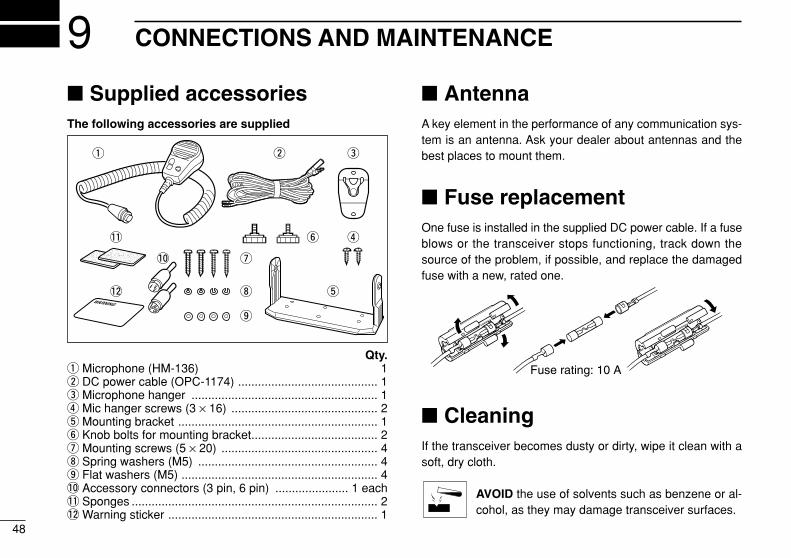
Supplied accessoriesThe following accessories are supplied
Qty.q Microphone (HM-136) 1w DC power cable (OPC-1174) .......................................... 1e Microphone hanger ........................................................ 1r Mic hanger screws (3 × 16) ............................................ 2t Mounting bracket ............................................................ 1y Knob bolts for mounting bracket...................................... 2u Mounting screws (5 × 20) ............................................... 4i Spring washers (M5) ...................................................... 4o Flat washers (M5) ........................................................... 4!0 Accessory connectors (3 pin, 6 pin) ...................... 1 each!1 Sponges .......................................................................... 2!2 Warning sticker ............................................................... 1
AntennaA key element in the performance of any communication sys-tem is an antenna. Ask your dealer about antennas and thebest places to mount them.
Fuse replacementOne fuse is installed in the supplied DC power cable. If a fuseblows or the transceiver stops functioning, track down thesource of the problem, if possible, and replace the damagedfuse with a new, rated one.
CleaningIf the transceiver becomes dusty or dirty, wipe it clean with asoft, dry cloth.
AVOID the use of solvents such as benzene or al-cohol, as they may damage transceiver surfaces.
Fuse rating: 10 A
WARNING
q w e
r
t
y
u
!1
!0
!2 i
o
48
9 CONNECTIONS AND MAINTENANCE
49
9CONNECTIONS AND MAINTENANCE
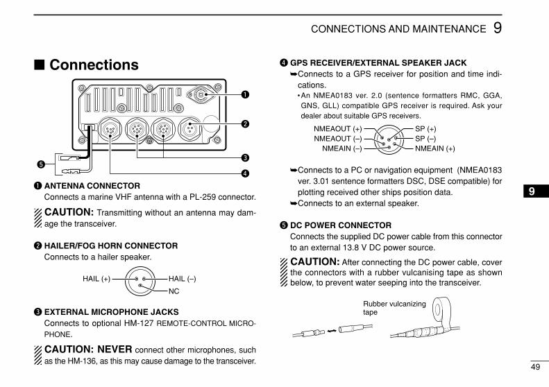
Connections
q ANTENNA CONNECTORConnects a marine VHF antenna with a PL-259 connector.
CAUTION: Transmitting without an antenna may dam-age the transceiver.
w HAILER/FOG HORN CONNECTORConnects to a hailer speaker.
e EXTERNAL MICROPHONE JACKSConnects to optional HM-127 REMOTE-CONTROL MICRO-
PHONE.
CAUTION: NEVER connect other microphones, suchas the HM-136, as this may cause damage to the transceiver.
r GPS RECEIVER/EXTERNAL SPEAKER JACKConnects to a GPS receiver for position and time indi-
cations.•An NMEA0183 ver. 2.0 (sentence formatters RMC, GGA,GNS, GLL) compatible GPS receiver is required. Ask yourdealer about suitable GPS receivers.
Connects to a PC or navigation equipment (NMEA0183ver. 3.01 sentence formatters DSC, DSE compatible) forplotting received other ships position data.
Connects to an external speaker.
t DC POWER CONNECTORConnects the supplied DC power cable from this connectorto an external 13.8 V DC power source.
CAUTION: After connecting the DC power cable, coverthe connectors with a rubber vulcanising tape as shownbelow, to prevent water seeping into the transceiver.
Rubber vulcanizingtape
NMEAOUT (+)NMEAOUT (–)
NMEAIN (+)NMEAIN (–)
SP (+)SP (–)
HAIL (+) HAIL (–)
NC
t
q
e
r
w
9
50
9 CONNECTIONS AND MAINTENANCE
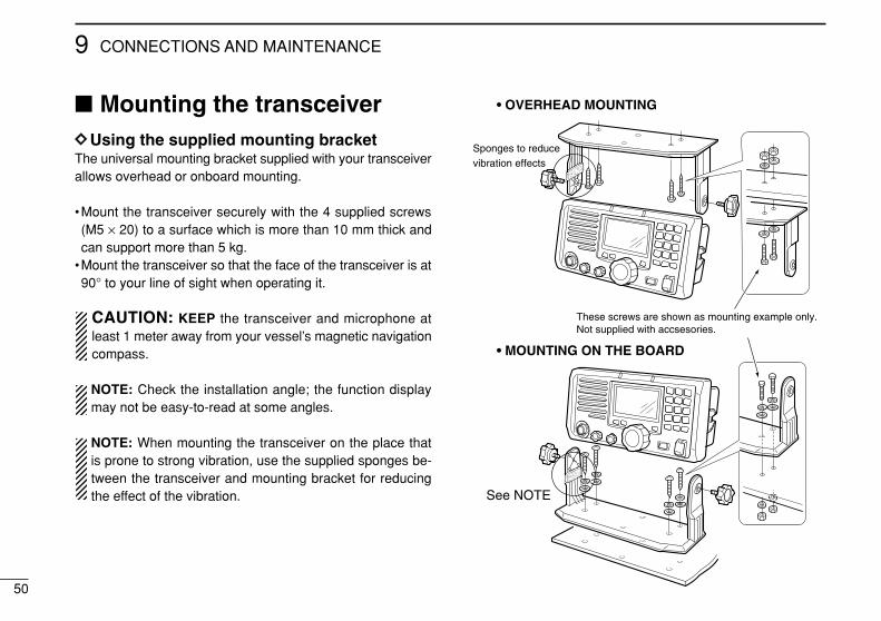
Mounting the transceiverDDUsing the supplied mounting bracketThe universal mounting bracket supplied with your transceiverallows overhead or onboard mounting.
•Mount the transceiver securely with the 4 supplied screws(M5 × 20) to a surface which is more than 10 mm thick andcan support more than 5 kg.
•Mount the transceiver so that the face of the transceiver is at90° to your line of sight when operating it.
CAUTION: KEEP the transceiver and microphone atleast 1 meter away from your vessel’s magnetic navigationcompass.
NOTE: Check the installation angle; the function displaymay not be easy-to-read at some angles.
NOTE: When mounting the transceiver on the place thatis prone to strong vibration, use the supplied sponges be-tween the transceiver and mounting bracket for reducingthe effect of the vibration.
These screws are shown as mounting example only. Not supplied with accsesories.
• OVERHEAD MOUNTING
• MOUNTING ON THE BOARD
Sponges to reduce vibration effects
See NOTE

51
9CONNECTIONS AND MAINTENANCE
DDUsing the optional MB-75An optional MB-75 FLUSH MOUNT is available for mountingthe transceiver to a flat surface such as an instrument panel.
CAUTION: KEEP the transceiver and microphone atleast 1 meter away from your vessel’s magnetic navigationcompass.
q Using the attached template, carefully cut a hole into theinstrument panel (or wherever you plan to mount the trans-ceiver).
w Slide the transceiver through the hole as shown below.
e Attach the 2 supplied bolts (M5 × 8 mm) on either side ofthe IC-M602.
r Attach the clamps on either side of the IC-M602.• Make sure that the clamps align parallel to the IC-M602’s body.
t Tighten the end bolts on the clamps (rotate clockwise) sothat the clamps press firmly against the inside of the in-strument control panel.
y Tighten the locking nuts (rotate counterclockwise) so thatthe IC-M602 is securely mounted in position as below.
u Connect the antenna and control cable, then return the in-strument control panel to its original place.
9
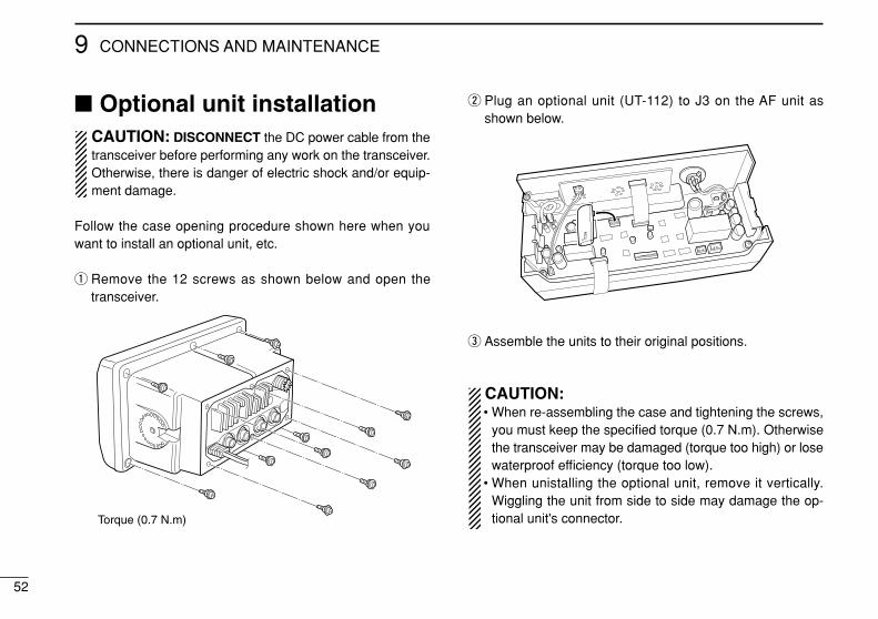
52
9 CONNECTIONS AND MAINTENANCE
Optional unit installationCAUTION: DISCONNECT the DC power cable from thetransceiver before performing any work on the transceiver.Otherwise, there is danger of electric shock and/or equip-ment damage.
Follow the case opening procedure shown here when youwant to install an optional unit, etc.
q Remove the 12 screws as shown below and open thetransceiver.
w Plug an optional unit (UT-112) to J3 on the AF unit asshown below.
e Assemble the units to their original positions.
CAUTION:• When re-assembling the case and tightening the screws,
you must keep the specified torque (0.7 N.m). Otherwisethe transceiver may be damaged (torque too high) or losewaterproof efficiency (torque too low).
• When unistalling the optional unit, remove it vertically.Wiggling the unit from side to side may damage the op-tional unit's connector.Torque (0.7 N.m)
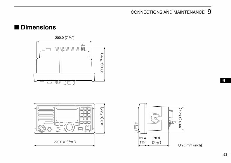
53
9CONNECTIONS AND MAINTENANCE
Dimensions
220.0 (8 21⁄32˝)31.4(1 1⁄4˝)
78.0(3 1⁄16˝)
110.
0 (4
11 ⁄
32˝)
109.
4 (4
29 ⁄
32˝)
200.0 (7 7⁄8˝)
Unit: mm (inch)
90.0
(3
17⁄3
2˝)
9
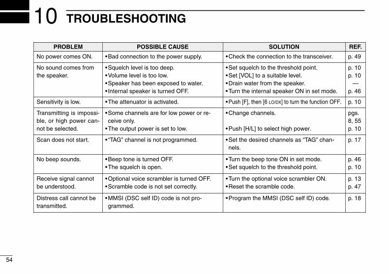
10 TROUBLESHOOTING
54
PROBLEM POSSIBLE CAUSE SOLUTION REF.
No power comes ON. •Bad connection to the power supply. •Check the connection to the transceiver. p. 49
No sound comes fromthe speaker.
•Squelch level is too deep.•Volume level is too low.•Speaker has been exposed to water.• Internal speaker is turned OFF.
•Set squelch to the threshold point.•Set [VOL] to a suitable level.•Drain water from the speaker.•Turn the internal speaker ON in set mode.
p. 10p. 10
—p. 46
Transmitting is impossi-ble, or high power can-not be selected.
•Some channels are for low power or re-ceive only.
•The output power is set to low.
•Change channels.
•Push [H/L] to select high power.
pgs.8, 55p. 10
Scan does not start. • “TAG” channel is not programmed. •Set the desired channels as “TAG” chan-nels.
p. 17
No beep sounds. •Beep tone is turned OFF.•The squelch is open.
•Turn the beep tone ON in set mode.•Set squelch to the threshold point.
p. 46p. 10
Receive signal cannotbe understood.
•Optional voice scrambler is turned OFF.•Scramble code is not set correctly.
•Turn the optional voice scrambler ON.•Reset the scramble code.
p. 13p. 47
Sensitivity is low. •The attenuator is activated. •Push [F], then [6 LO/DX] to turn the function OFF. p. 10
Distress call cannot betransmitted.
•MMSI (DSC self ID) code is not pro-grammed.
•Program the MMSI (DSC self ID) code. p. 18
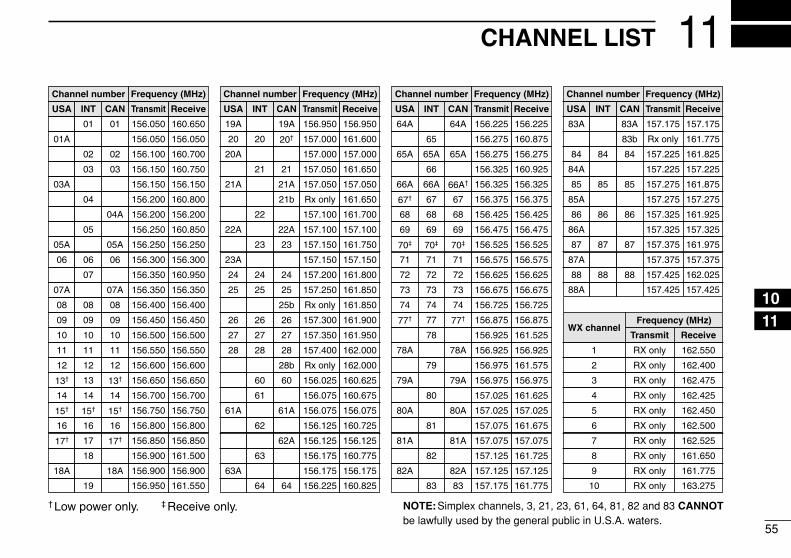
11CHANNEL LIST
55
Channel number
USA CAN Transmit Receive
01 156.050 160.650
01A 156.050 156.050
02 156.100 160.700
03 156.150 160.750
03A 156.150 156.150
156.200 160.800
04A 156.200 156.200
156.250 160.850
05A 05A 156.250 156.250
06 06 156.300 156.300
156.350 160.950
07A 07A 156.350 156.350
08 08 156.400 156.400
09 09 156.450 156.450
10 10 156.500 156.500
11 11 156.550 156.550
12 12 156.600 156.600
13† 13† 156.650 156.650
14 14 156.700 156.700
15† 15† 156.750 156.750
16 16 156.800 156.800
17† 17† 156.850 156.850
156.900 161.500
18A 18A 156.900 156.900
Frequency (MHz)
INT
01
02
03
04
05
06
07
08
09
10
11
12
13
14
15†
16
17
18
Channel number Frequency (MHz)
USA CAN Transmit Receive
19A 19A 156.950 156.950
20 20† 157.000 161.600
21 157.050 161.650
21A 21A 157.050 157.050
157.100 161.700
22A 22A 157.100 157.100
23 157.150 161.750
23A 157.150 157.150
24 24 157.200 161.800
25 25 157.250 161.850
26 26 157.300 161.900
27 27 157.350 161.950
28 28 157.400 162.000
60 156.025 160.625
156.075 160.675
61A 61A 156.075 156.075
156.125 160.725
62A 156.125 156.125
156.175 160.775
63A 156.175 156.175
64 156.225 160.825
INT
20
21
22
23
24
25
26
27
28
60
61
62
63
64
20A 157.000 157.000
Channel number
66A
Frequency (MHz)
66A†
USA CAN Transmit Receive
64A 64A 156.225 156.225
65A 65A 156.275 156.275
156.325 160.925
67† 67 156.375 156.375
68 68 156.425 156.425
69 69 156.475 156.475
70‡ 70‡ 156.525 156.525
71 71 156.575 156.575
72 72 156.625 156.625
73 73 156.675 156.675
74 74 156.725 156.725
77† 77† 156.875 156.875
156.925 161.525
78A 78A 156.925 156.925
156.975 161.575
79A 79A 156.975 156.975
157.025 161.625
80A 80A 157.025 157.025
157.075 161.675
81A 81A 157.075 157.075
157.125 161.725
82A 82A 157.125 157.125
INT
65A
66
67
68
69
70‡
71
72
73
74
77
78
79
80
81
82
156.325 156.32566A
Channel number
84A
Frequency (MHz)
USA CAN Transmit Receive
83A 83A 157.175 157.175
84 84 157.225 161.825
85 85 157.275 161.875
85A 157.275 157.275
86 86 157.325 161.925
86A 157.325 157.325
87 87 157.375 161.975
87A 157.375 157.375
88 88 157.425 162.025
88A 157.425 157.425
INT
84
85
86
87
88
157.225 157.225
WX channel
4
Frequency (MHz)
Transmit Receive
1 RX only 162.550
2 RX only 162.400
3 RX only 162.475
5 RX only 162.450
6 RX only 162.500
7 RX only 162.525
8 RX only 161.650
9 RX only 161.775
10 RX only 163.275
RX only 162.425
† Low power only. ‡ Receive only.
156.950 161.55019
21b Rx only 161.650
25b Rx only 161.850
156.275 160.87565
28b Rx only 162.000
83 157.175 161.77583
83b Rx only 161.775
NOTE:Simplex channels, 3, 21, 23, 61, 64, 81, 82 and 83 CANNOTbe lawfully used by the general public in U.S.A. waters.
1011
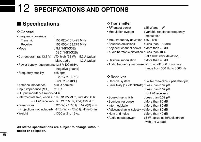
56
12 SPECIFICATIONS AND OPTIONS
SpecificationsDDGeneral•Frequency coverage :
Transmit 156.025–157.425 MHzReceive 156.050–163.275 MHz
•Mode : FM (16K0G3E)DSC (16K0G2B)
•Current drain (at 13.8 V) : TX high (25 W) 5.2 A typicalMax. audio 1.2 A typical
•Power supply requirement: 13.8 V DC ±15%(negative ground)
•Frequency stability : ±5 ppm(–20°C to +60°C; –4°F to +140°F)
•Antenna impedance : 50 Ω nominal• Input impedance (MIC) : 2 kΩ•Output impedance (audio): 4 Ω• Intermediate frequencies : 1st; 31.05 MHz, 2nd; 450 kHz
(CH 70 receiver) 1st; 21.7 MHz, 2nd; 450 kHz•Dimensions : 220(W)×110(H)×109.4(D) mm(Projections not included) 8 21⁄32(W)×4 11⁄32(H)×4 5⁄16(D) in
•Weight : 1350 g; 2 lb 16 oz
DDTransmitter•RF output power : 25 W and 1 W•Modulation system : Variable reactance frequency
modulation•Max. frequency deviation : ±5.0 kHz•Spurious emissions : Less than –70 dBc•Adjacent channel power : More than 70 dB•Audio harmonic distortion : Less than 10%
(at 1 kHz, 60% deviation)•Residual modulation : More than 40 dB•Audio frequency response: +1 to –3 dB of 6 dB/octave
range from 300 Hz to 3000 Hz
DDReceiver•Receive system : Double conversion superheterodyne•Sensitivity (12 dB SINAD) : Less than 0.32 µV
Less than 0.32 µV (CH 70 receiver)
•Squelch sensitivity : Less than 0.32 µV•Spurious response : More than 80 dB• Intermodulation : More than 80 dB•Adjacent channel selectivity : More than 80 dB•Hum and noise : More than 40 dB•Audio output power : 5 W typical at 10% distortion
with a 4 Ω load
All stated specifications are subject to change withoutnotice or obligation.

57
12SPECIFICATION AND OPTIONS
Options•MB-75 FLUSH MOUNT (p. 51)For mounting the transceiver to a panel.
•UT-112 VOICE SCRAMBLER UNIT (pgs. 13, 47)Ensures private communications. 32 codes are available. Notavailable in some countries.
•HM-127 REMOTE-CONTROL MICROPHONE (p. 58)External microphone-type controller. Provides optional inter-com operation. 6 m (20 feet) microphone cable and mount-ing base included. Black and white colors are available.
•HM-136 SMART-SPEAKER-MICROPHONE (p. 7)Same as supplied. Black and white colors are available.
•OPC-999 MICROPHONE EXTENSION CABLE6 m (20 feet) microphone extension cable for optionalHM-127. Up to 2 OPC-999 can be connected. (18 m; 60 feetmaximum)
12

58
13 HM-127 REMOTE-CONTROL MICROPHONE OPTIONAL
Panel descriptionThe optional HM-127 remotely controls the IC-M602 and pro-vides an optional intercom function.
q POWER SWITCH [PWR] (pgs. 10, 65)Push for 2 sec. to turn the HM-127 power ON or OFFwhen the IC-M602 power is turned ON.
w PTT SWITCH [PTT] (pgs. 10, 65)Push and hold to transmit; release to receive.
e CHANNEL UP/DOWN SWITCHES [YY]/[ZZ] Push either switch to change the operating channel, set
mode contents, etc. (pgs. 10, 65)Push either switch to adjust audio level or noise squelch
level after [VOL] or [SQL] is pushed, respectively. (pgs.10, 65)
Push either switch to adjust the brightness of the LCD andswitch backlight after [VOL] is pushed for 1 sec. (p. 66)
In set mode, changes setting of the selected item. (pgs.44, 69)
Checks tag channels or changes scanning direction dur-ing scan. (pgs. 17, 68)
r CHANNEL 16/CALL CHANNEL SWITCH [16•9]Selects channel 16 when pushed. (pgs. 8, 64)Selects call channel when pushed for 1 sec. (pgs. 8, 64)
• “CALL” appears when call channel is selected.
Push for 3 sec. to enter call channel programming con-dition when call channel is selected. (pgs. 11, 67)
While pushing [H/L], enters memory name programmingcondition. (pgs. 11, 70)
Enters set mode when pushed while turning power ON.(pgs. 44, 69)
t CHANNEL/DUALWATCH/TRI-WATCH SWITCH[CH/WX•DW•U/I/C]Selects and toggles the regular channels and weather
channel when pushed momentarily. (pgs. 9, 64)
q
w
r
euyt
i
o!0
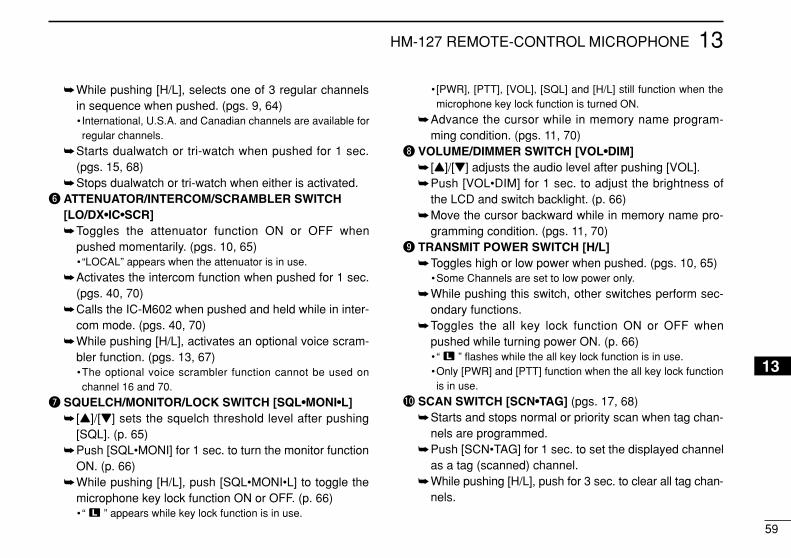
59
13HM-127 REMOTE-CONTROL MICROPHONE
While pushing [H/L], selects one of 3 regular channelsin sequence when pushed. (pgs. 9, 64)• International, U.S.A. and Canadian channels are available forregular channels.
Starts dualwatch or tri-watch when pushed for 1 sec. (pgs. 15, 68)
Stops dualwatch or tri-watch when either is activated.y ATTENUATOR/INTERCOM/SCRAMBLER SWITCH
[LO/DX•IC•SCR]Toggles the attenuator function ON or OFF when
pushed momentarily. (pgs. 10, 65)• “LOCAL” appears when the attenuator is in use.
Activates the intercom function when pushed for 1 sec.(pgs. 40, 70)
Calls the IC-M602 when pushed and held while in inter-com mode. (pgs. 40, 70)
While pushing [H/L], activates an optional voice scram-bler function. (pgs. 13, 67)•The optional voice scrambler function cannot be used onchannel 16 and 70.
u SQUELCH/MONITOR/LOCK SWITCH [SQL•MONI•L] [Y]/[Z] sets the squelch threshold level after pushing
[SQL]. (p. 65)Push [SQL•MONI] for 1 sec. to turn the monitor function
ON. (p. 66)While pushing [H/L], push [SQL•MONI•L] to toggle the
microphone key lock function ON or OFF. (p. 66)• “ T ” appears while key lock function is in use.
• [PWR], [PTT], [VOL], [SQL] and [H/L] still function when themicrophone key lock function is turned ON.
Advance the cursor while in memory name program-ming condition. (pgs. 11, 70)
i VOLUME/DIMMER SWITCH [VOL•DIM] [Y]/[Z] adjusts the audio level after pushing [VOL]. Push [VOL•DIM] for 1 sec. to adjust the brightness of
the LCD and switch backlight. (p. 66)Move the cursor backward while in memory name pro-
gramming condition. (pgs. 11, 70)o TRANSMIT POWER SWITCH [H/L]
Toggles high or low power when pushed. (pgs. 10, 65)•Some Channels are set to low power only.
While pushing this switch, other switches perform sec-ondary functions.
Toggles the all key lock function ON or OFF whenpushed while turning power ON. (p. 66)• “ T ” flashes while the all key lock function is in use.•Only [PWR] and [PTT] function when the all key lock functionis in use.
!0 SCAN SWITCH [SCN•TAG] (pgs. 17, 68)Starts and stops normal or priority scan when tag chan-
nels are programmed.Push [SCN•TAG] for 1 sec. to set the displayed channel
as a tag (scanned) channel. While pushing [H/L], push for 3 sec. to clear all tag chan-
nels.
13
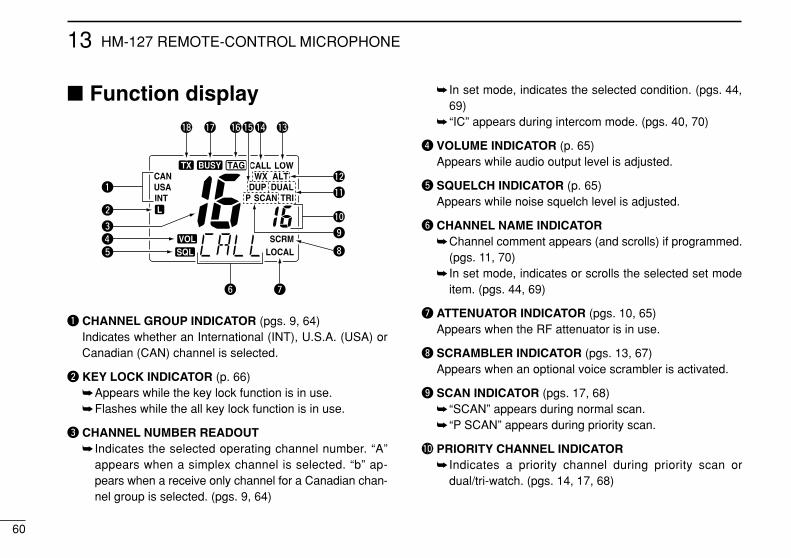
60
13 HM-127 REMOTE-CONTROL MICROPHONE
Function display
q CHANNEL GROUP INDICATOR (pgs. 9, 64)Indicates whether an International (INT), U.S.A. (USA) orCanadian (CAN) channel is selected.
w KEY LOCK INDICATOR (p. 66)Appears while the key lock function is in use.Flashes while the all key lock function is in use.
e CHANNEL NUMBER READOUT Indicates the selected operating channel number. “A”
appears when a simplex channel is selected. “b” ap-pears when a receive only channel for a Canadian chan-nel group is selected. (pgs. 9, 64)
In set mode, indicates the selected condition. (pgs. 44,69)
“IC” appears during intercom mode. (pgs. 40, 70)
r VOLUME INDICATOR (p. 65)Appears while audio output level is adjusted.
t SQUELCH INDICATOR (p. 65)Appears while noise squelch level is adjusted.
y CHANNEL NAME INDICATORChannel comment appears (and scrolls) if programmed.
(pgs. 11, 70) In set mode, indicates or scrolls the selected set mode
item. (pgs. 44, 69)
u ATTENUATOR INDICATOR (pgs. 10, 65)Appears when the RF attenuator is in use.
i SCRAMBLER INDICATOR (pgs. 13, 67)Appears when an optional voice scrambler is activated.
o SCAN INDICATOR (pgs. 17, 68) “SCAN” appears during normal scan. “P SCAN” appears during priority scan.
!0 PRIORITY CHANNEL INDICATOR Indicates a priority channel during priority scan or
dual/tri-watch. (pgs. 14, 17, 68)
CALLWX ALT
DUPP SCAN
SCRMLOCAL
TRIDUAL
LOWTAGCANUSAINTL
TX BUSY
VOLSQL
q
w
rt
e
!8 !7 !4!5 !3
!2
!1
!0
o
i
uy
!6

61
13HM-127 REMOTE-CONTROL MICROPHONE
!1 DUAL/TRI WATCH INDICATOR (pgs. 15, 68)“DUAL” appears during dualwatch; “TRI” during tri-watch.
!2 WEATHER CHANNEL INDICATOR (pgs. 9, 64) “WX” appears when a weather channel is selected. “WX ALT” appears when the weather alert function is
in use; flashes when an alert tone is received.
!3 LOW POWER INDICATOR (pgs. 10, 65)Appears when low power is selected.
!4 CALL CHANNEL INDICATOR (pgs. 8, 64)Appears when the call channel is selected.
!5 DUPLEX INDICATOR (pgs. 9, 64)Appears when a duplex channel is selected.
!6 TAG CHANNEL INDICATOR (pgs. 17, 68)Appears when a tag channel is selected.
!7 BUSY INDICATOR (pgs. 10, 65, 66)Appears when receiving a signal or when the squelchopens.
!8 TRANSMIT INDICATOR (pgs. 10, 65)Appears while transmitting.
HM-127 supplied accessoriesAccessories included with the HM-127: Qty.q Connection cable (OPC-1000: 6 m; 20 ft) ...................... 1w Mounting base ................................................................ 1e Microphone hanger ........................................................ 1r Screws (M3 × 16; tapping) ............................................. 5
q
w e
r
13
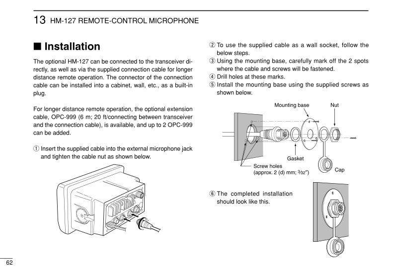
62
13 HM-127 REMOTE-CONTROL MICROPHONE
InstallationThe optional HM-127 can be connected to the transceiver di-rectly, as well as via the supplied connection cable for longerdistance remote operation. The connector of the connectioncable can be installed into a cabinet, wall, etc., as a built-inplug.
For longer distance remote operation, the optional extensioncable, OPC-999 (6 m; 20 ft/connecting between transceiverand the connection cable), is available, and up to 2 OPC-999can be added.
q Insert the supplied cable into the external microphone jackand tighten the cable nut as shown below.
w To use the supplied cable as a wall socket, follow thebelow steps.
e Using the mounting base, carefully mark off the 2 spotswhere the cable and screws will be fastened.
r Drill holes at these marks.t Install the mounting base using the supplied screws as
shown below.
y The completed installationshould look like this.
Gasket
Cap
Mounting base Nut
Screw holes(approx. 2 (d) mm; 3⁄32″)
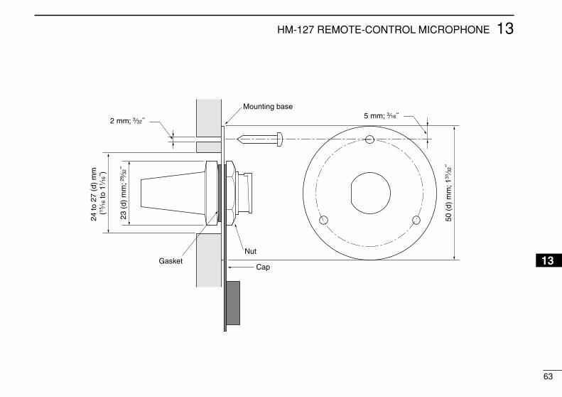
63
13HM-127 REMOTE-CONTROL MICROPHONE
50 (
d) m
m; 1
31⁄32
˝
23 (
d) m
m; 29
⁄32˝
24 to
27
(d)
mm
(15
⁄16 to
11 ⁄1
6˝)
5 mm; 3⁄16˝
Gasket
Mounting base
Cap
Nut
2 mm; 3⁄32˝
13
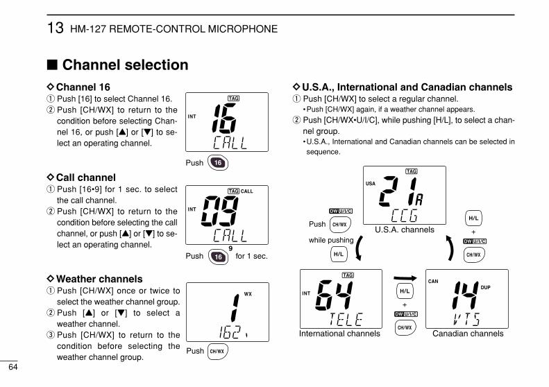
64
13 HM-127 REMOTE-CONTROL MICROPHONE
Channel selectionDDChannel 16q Push [16] to select Channel 16.w Push [CH/WX] to return to the
condition before selecting Chan-nel 16, or push [Y] or [Z] to se-lect an operating channel.
DDCall channelq Push [16•9] for 1 sec. to select
the call channel.w Push [CH/WX] to return to the
condition before selecting the callchannel, or push [Y] or [Z] to se-lect an operating channel.
DDWeather channelsq Push [CH/WX] once or twice to
select the weather channel group.w Push [Y] or [Z] to select a
weather channel.e Push [CH/WX] to return to the
condition before selecting theweather channel group.
DDU.S.A., International and Canadian channelsq Push [CH/WX] to select a regular channel.
•Push [CH/WX] again, if a weather channel appears.
w Push [CH/WX•U/I/C], while pushing [H/L], to select a chan-nel group.•U.S.A., International and Canadian channels can be selected insequence.
Push
Push for 1 sec.
Push
Push
while pushingU.S.A. channels
Canadian channelsInternational channels
+
+
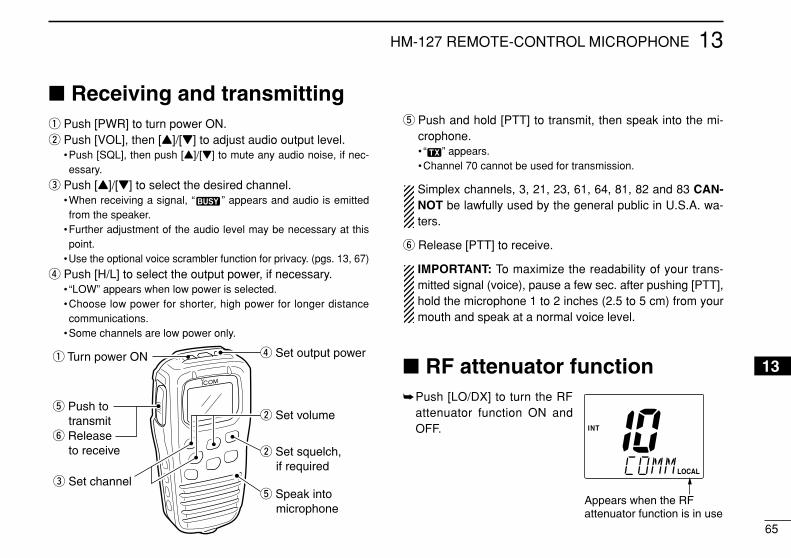
65
13HM-127 REMOTE-CONTROL MICROPHONE
Receiving and transmittingq Push [PWR] to turn power ON.w Push [VOL], then [Y]/[Z] to adjust audio output level.
•Push [SQL], then push [Y]/[Z] to mute any audio noise, if nec-essary.
e Push [Y]/[Z] to select the desired channel.•When receiving a signal, “ ” appears and audio is emittedfrom the speaker.
•Further adjustment of the audio level may be necessary at thispoint.
•Use the optional voice scrambler function for privacy. (pgs. 13, 67)
r Push [H/L] to select the output power, if necessary.• “LOW” appears when low power is selected.•Choose low power for shorter, high power for longer distancecommunications.
•Some channels are low power only.
t Push and hold [PTT] to transmit, then speak into the mi-crophone.• “ ” appears.•Channel 70 cannot be used for transmission.
Simplex channels, 3, 21, 23, 61, 64, 81, 82 and 83 CAN-NOT be lawfully used by the general public in U.S.A. wa-ters.
y Release [PTT] to receive.
IMPORTANT: To maximize the readability of your trans-mitted signal (voice), pause a few sec. after pushing [PTT],hold the microphone 1 to 2 inches (2.5 to 5 cm) from yourmouth and speak at a normal voice level.
RF attenuator functionPush [LO/DX] to turn the RF
attenuator function ON andOFF.
w Set volume
w Set squelch, if required
r Set output power
t Speak into microphone
q Turn power ON
e Set channel
t Push to transmity Release to receive
Appears when the RFattenuator function is in use
13

66
13 HM-127 REMOTE-CONTROL MICROPHONE
Lock functionsThe lock function electronically locks keys and switches toprevent accidental changes and function access from the mi-crophone.•All keys, switches and controllers on the transceiver are functional.
DDActivating the lockfunction
Push [SQL] while pushing[H/L] to turn the lock functionON or OFF.• “ ” appears.•Only [PWR], [PTT], [H/L],[SQL•MONI], [VOL]+[Y]/[Z] and[SQL]+[Y]/[Z] are functional.
DDActivating the all keylock function
Turn the power ON by pushing[PWR] while pushing [H/L] toturn the all key lock functionON or OFF.• “ ” flashes.•Only [PWR] and [PTT] are func-tional.
Display backlightingThe function display and switches can be backlit for bettervisibility under low light conditions. The backlighting conditioncan also be adjusted independently from the transceiver.
q Push [VOL•DIM] for 1 sec. to enter backlight adjustingmode.• “ ” with the number of the backlight level appears in the chan-nel name indicator.
w Push [Y]/[Z] to adjust the backlight level.•The backlight level is adjustable between 0 (light OFF) and 7(brightest).
Monitor functionThe monitor function releases the noise squelch mute of themicrophone only. (An independent noise squelch system isemployed.)Push [SQL•MONI] for 1 sec. to activate the monitor func-
tion.• “ ” flashes and audio is emitted.•Any key cancels the monitor function.
Appears when the lockfunction is in use.
Flashes when the all lockfunction is in use.
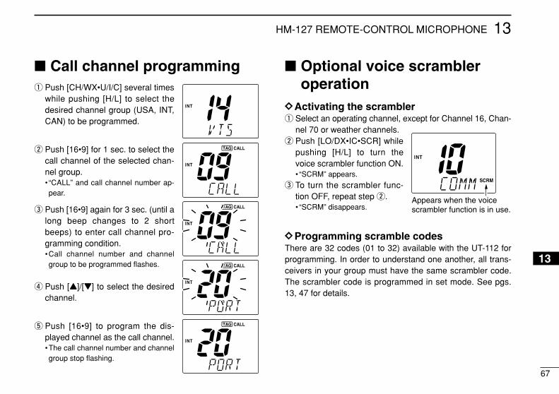
67
13HM-127 REMOTE-CONTROL MICROPHONE
Call channel programmingq Push [CH/WX•U/I/C] several times
while pushing [H/L] to select thedesired channel group (USA, INT,CAN) to be programmed.
w Push [16•9] for 1 sec. to select thecall channel of the selected chan-nel group.• “CALL” and call channel number ap-pear.
e Push [16•9] again for 3 sec. (until along beep changes to 2 shortbeeps) to enter call channel pro-gramming condition.•Call channel number and channelgroup to be programmed flashes.
r Push [Y]/[Z] to select the desiredchannel.
t Push [16•9] to program the dis-played channel as the call channel.•The call channel number and channelgroup stop flashing.
Optional voice scrambleroperation
DDActivating the scramblerq Select an operating channel, except for Channel 16, Chan-
nel 70 or weather channels.w Push [LO/DX•IC•SCR] while
pushing [H/L] to turn thevoice scrambler function ON.• “SCRM” appears.
e To turn the scrambler func-tion OFF, repeat step w.• “SCRM” disappears.
DDProgramming scramble codesThere are 32 codes (01 to 32) available with the UT-112 forprogramming. In order to understand one another, all trans-ceivers in your group must have the same scrambler code.The scrambler code is programmed in set mode. See pgs.13, 47 for details.
Appears when the voicescrambler function is in use.
13
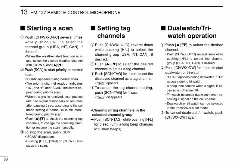
68
13 HM-127 REMOTE-CONTROL MICROPHONE
Starting a scanq Push [CH/WX•U/I/C] several times
while pushing [H/L] to select thechannel group (USA, INT, CAN), ifdesired.•When the weather alert function is inuse, select the desired weather channelwith [CH/WX] and [Y]/[Z].
w Push [SCN] to start priority or normalscan.• “SCAN” appears during normal scan.•The priority channel readout indicates“16”, and “P” and “SCAN” indicators ap-pear during priority scan.
•When a signal is received, scan pausesuntil the signal disappears or resumesafter pausing 5 sec. according to the setmode setting (Channel 16 is still moni-tored during priority scan).
•Push [Y]/[Z] to check the scanning tagchannels, to change the scanning direc-tion or resume the scan manually.
e To stop the scan, push [SCN].• “SCAN” disappears.•Pushing [PTT], [16•9] or [CH/WX] alsostops the scan.
Setting tagchannels
q Push [CH/WX•U/I/C] several timeswhile pushing [H/L] to select thechannel group (USA, INT, CAN), ifdesired.
w Push [Y]/[Z] to select the desiredchannel to set as a tag channel.
e Push [SCN•TAG] for 1 sec. to set thedisplayed channel as a tag channel.• “ ” appears.
r To cancel the tag channel setting,push [SCN•TAG] for 1 sec.• “ ” disappears.
•Clearing all tag channels in theselected channel group
Push [SCN•TAG] while pushing [H/L]for 3 sec. (until a long beep changesto 2 short beeps).
Dualwatch/Tri-watch operation
q Push [Y]/[Z] to select the desiredchannel.•Push [CH/WX•U/I/C] several times whilepushing [H/L] to select the channelgroup (USA, INT, CAN), if desired.
w Push [CH/WX•DW] for 1 sec. to startdualwatch or tri-watch.• “DUAL” appears during dualwatch; “TRI”appears during tri-watch.
•A beep tone sounds when a signal is re-ceived on Channel 16.
•Tri-watch becomes dualwatch when re-ceiving a signal on the call channel.
•Dualwatch or tri-watch can be selectedin the transceiver’s set mode.
e To cancel dualwatch/tri-watch, push[CH/WX•DW] again.
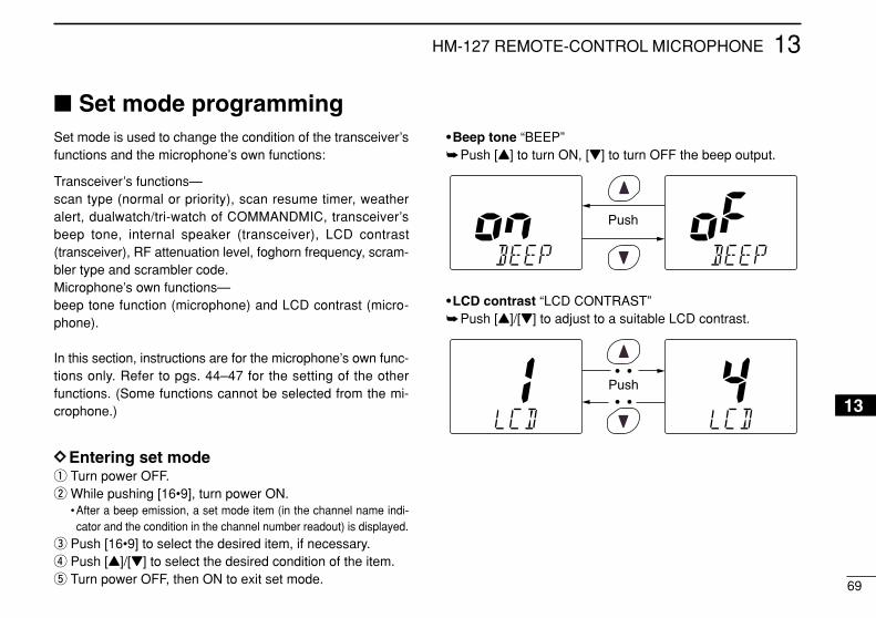
69
13HM-127 REMOTE-CONTROL MICROPHONE
Set mode programmingSet mode is used to change the condition of the transceiver’sfunctions and the microphone’s own functions:
Transceiver’s functions— scan type (normal or priority), scan resume timer, weatheralert, dualwatch/tri-watch of COMMANDMIC, transceiver’sbeep tone, internal speaker (transceiver), LCD contrast(transceiver), RF attenuation level, foghorn frequency, scram-bler type and scrambler code.Microphone’s own functions— beep tone function (microphone) and LCD contrast (micro-phone).
In this section, instructions are for the microphone’s own func-tions only. Refer to pgs. 44–47 for the setting of the otherfunctions. (Some functions cannot be selected from the mi-crophone.)
DDEntering set modeq Turn power OFF.w While pushing [16•9], turn power ON.
•After a beep emission, a set mode item (in the channel name indi-cator and the condition in the channel number readout) is displayed.
e Push [16•9] to select the desired item, if necessary.r Push [Y]/[Z] to select the desired condition of the item.t Turn power OFF, then ON to exit set mode.
•Beep tone “BEEP”Push [Y] to turn ON, [Z] to turn OFF the beep output.
•LCD contrast “LCD CONTRAST”Push [Y]/[Z] to adjust to a suitable LCD contrast.
Push• •
• •
Push
13
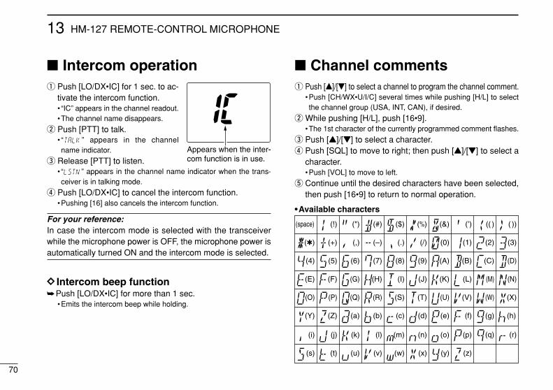
70
13 HM-127 REMOTE-CONTROL MICROPHONE
Intercom operationq Push [LO/DX•IC] for 1 sec. to ac-
tivate the intercom function.• “IC” appears in the channel readout.•The channel name disappears.
w Push [PTT] to talk.• “ ” appears in the channelname indicator.
e Release [PTT] to listen.• “ ” appears in the channel name indicator when the trans-ceiver is in talking mode.
r Push [LO/DX•IC] to cancel the intercom function.•Pushing [16] also cancels the intercom function.
For your reference:In case the intercom mode is selected with the transceiverwhile the microphone power is OFF, the microphone power isautomatically turned ON and the intercom mode is selected.
DD Intercom beep functionPush [LO/DX•IC] for more than 1 sec.
•Emits the intercom beep while holding.
Channel commentsq Push [Y]/[Z] to select a channel to program the channel comment.
•Push [CH/WX•U/I/C] several times while pushing [H/L] to selectthe channel group (USA, INT, CAN), if desired.
w While pushing [H/L], push [16•9].•The 1st character of the currently programmed comment flashes.
e Push [Y]/[Z] to select a character.r Push [SQL] to move to right; then push [Y]/[Z] to select a
character.•Push [VOL] to move to left.
t Continue until the desired characters have been selected,then push [16•9] to return to normal operation.
•Available characters
(r)
(s) (t) (u) (v) (w) (x) (y) (z)
(q)
(3)
(D)
(N)
(X)
(h)
(+)
(4)
(E)
(O)
(Y)
(i)
(–)
(5)
(F)
(P)
(Z)
(j)
()
(6)
(G)
(Q)
(a)
(k)
(/)
(7)
(H)
(R)
(b)
(l)
(,)
(8)
(I)
(S)
(c)
(m)
(space)
(9)
(T)
(d)
(n)
(0)
(A)
(U)
(e)
(o)
(1)
(B)
(V)
(f)
(p)
(2)
(C)
(J) (K) (L) (M)
(W)
(g)
(.)
( ))(( )(’)(&)(%)($)(#)(")(!)
Appears when the inter-com function is in use.

TEMPLATE
Unit: mm (inch)
24 to 27 (d) mm (15⁄16 to 11⁄16˝)
2 mm; 3⁄32˝HM-127
HM-127 TEMPLATE
Cut
her
e

Count on us!
1-1-32 Kamiminami, Hirano-ku, Osaka 547-0003 Japan
A-6217H-1EX-qPrinted in Japan© 2002 Icom Inc.