Embed Size (px)
Citation preview
VHDL Language and Syntax

VHDL: Basic Concepts
• Case insensitive
• Comments: „--' until end of line
• Statements are terminated by ';'
• List delimiter: ','
• Signal assignment: '<='
• Variable assignment: „:='
• User defined names: letters, numbers, underscores but start with a letter

VHDL: Design Structural Elements
Entity describes an interface consisting of the port list
Architecture contains the description of the internal behavior of the corresponding
module
Configuration is used for simulation purposes only and selects the entity-architecture
pairs to build the complete model
Process itself, as a whole object, is concurrent to other processes. Generally statements
are concurrent while “process” allows execution of inner sequential assignments
Package holds the definition of commonly used data types, constants and subprograms
Library is the logical name of a collection of compiled VHDL units (object code)

Entity
entity HALFADDER is -- Interface description
port(A, B: in std_logic; -- No behavioral definition
SUM, CARRY: out std_logic); -- port mode in blue
end HALFADDER; -- keywords in red
entity FULLADDER is
port
(
A, B: in std_logic_vector(3 downto 0);
CARRYIN: in std_logic;
SUM: out std_logic_vector(3 downto 0);
CARRYOUT: out std_logic
);
end FULLADDER;

Entity Port Modes
• in: signal values are read-only
• out: signal values are write-only
• inout: bidirectional port
• buffer: comparable to out signal values may be read, as well
The mode of an entity port restricts the direction of the data flow while
internal signals do not have a data flow direction: can be written and read.
Input Output
Inout BufferD

Entity and Architecture
entity HALFADDER is -- One entity can have several architectures
-- (different implementations) with different names.
port(A, B: in std_logic; -- No behavioral definition
SUM, CARRY: out std_logic);
end HALFADDER;
architecture RTL of HALFADDER is -- Always connected with a
begin -- specific entity
SUM <= A xor B; -- One architecture has only one entity
CARRY <= A and B; -- Entity ports are signals within the architecture
end RTL; -- Architecture contains concurrent statements
signal(output port) assignment

Architecture
-- 4-bit 3-level shift register
Library IEEE;
Use IEEE.std_logic_1164.All;
Use IEEE.std_logic_arith.All;
ENTITY shift_register is
Port(data: in std_logic_vector(3 downto 0);
Ck: in std_logic;
Exit:out std_logic_vector(3 downto 0));
END shift_register;
ARCHITECTURE behavioral (RTL)
of shift_register is
-- additional signals (declarative part)
signal sig0,sig1:std_logic_vector(3 downto 0);
begin
-- Concurrent Statements after begin
RUN:PROCESS(ck) – Synchronous process
begin
-- Sequential Statements after begin
if( ck‟event and ck=„1„)then;
sig0 <= data; -- First Phase
sig1 <= sig0; -- Second Phase
exit <= sig1; -- Third Phase
end if;
END PROCESS;
END behavioral (RTL);
The declarative part is located between
the keywords ' is ' and ' begin '. New
objects that are needed only within the
architecture as constants, datatypes,
signals, subprograms, etc. can be
declared there.

ArchitectureARCHITECTURE behavioral (RTL)
of Shift_Register is
-- additional signals (declarative part)
signal sig0,sig1:std_logic_vector(3 downto 0);
begin
-- Concurrent Statements after begin
RUN:PROCESS (ck) -- Rise-edged process
begin
-- Sequential Statements after begin
-- wait until ck'event and ck='1';
if (ck'event and ck='1„)then -- alternative
sig0 <= data; -- First Phase
sig1 <= sig0; -- Second Phase
exit <= sig1; -- Third Phase
end if;
END PROCESS;
END behavioral (RTL);
The definition part is initiated by the
keyword ' begin ' and holds concurrent
statements such as signal assignments,
process statements which group together
sequential statements, and component
instantiations. Concurrency means that
the order in which they appear is not
important.
The data types on the left and on the
right side must be identical. The signal
exit is a port defined by the port
declaration of the entity

Hierarchical Model
HA 1 HA 2
Or_Gate
A
B
Carry_In
Sum
Carry_Out
Carry_Out_2
Carry_Out_1
Sum_1
A Full-Hadder modeled by means of two cascaded Half-Adders
entity FULL is
port (A,B, Carry_In: in std_logic;
Sum, Carry_Out: out std_logic);
end FULL;
architecture Structural (RTL) of FULL is
signal Carry_Out_1, Carry_Out_2,
Sum_1 : std_logic;
component HALFADDER
port (A, B : in std_logic;
SUM, CARRY : out std_logic);
end component;
component Or_Gate
port (A, B : in std_logic;
Y : out std_logic);
end component;
begin
HA1: HALFADDER
port map( A, B, Sum_1, Carry_Out_1);
HA2: HALFADDER
port map ( Sum_1, Carry_In, Sum, Carry_Out_2);
Or_Gate1: Or_Gate
port map ( Carry_Out_1, Carry_Out_2, Carry_Out); -- default: Positional Association
end Structural (RTL);
In component declaration all module types must be declared before the
'begin' keyword of the architecture statement. Just the interface of the
modules is given here and their use still remains unspecified. The port
list elements of the component are called local elements, but are not
signals !
Component Instantiations

Component Instantiation: Named Association
architecture Structural (RTL) of FULL is
signal a1, a2,
a3 : bit;
component HALFADDER
port (A, B : in bit;
SUM, CARRY : out bit);
end component;
component Or_Gate
port (A, B : in bit;
Y : out bit);
end component;
begin
HA1: HALFADDER
port map( A => A, B => B, SUM => a1, CARRY => a2);
HA2: HALFADDER
port map (A => a1, B => Carry_In, SUM => Sum, CARRY => a3);
Or_Gate1: Or_Gate
port map (A => a2, B => a3, Y => Carry_Out);
end Structural (RTL);
HA 1 HA 2
Or_Gate
A
B
Carry_In
Sum
Carry_Out
a3
a2
a1
Left side: "formals“; port names from component declaration
Right side: "actuals“; architecture signals
Independent of order in component declaration
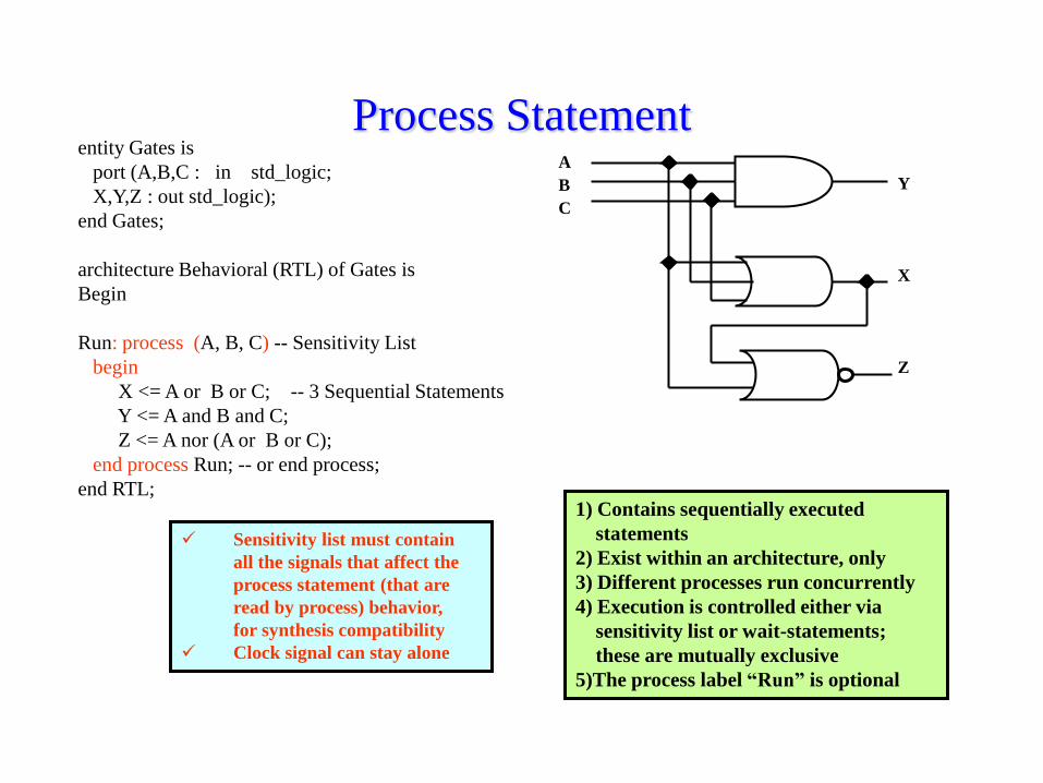
Process Statemententity Gates is
port (A,B,C : in std_logic;
X,Y,Z : out std_logic);
end Gates;
architecture Behavioral (RTL) of Gates is
Begin
Run: process (A, B, C) -- Sensitivity List
begin
X <= A or B or C; -- 3 Sequential Statements
Y <= A and B and C;
Z <= A nor (A or B or C);
end process Run; -- or end process;
end RTL;
A
B
C
Y
X
Z
1) Contains sequentially executed
statements
2) Exist within an architecture, only
3) Different processes run concurrently
4) Execution is controlled either via
sensitivity list or wait-statements;
these are mutually exclusive
5)The process label “Run” is optional
Sensitivity list must contain
all the signals that affect the
process statement (that are
read by process) behavior,
for synthesis compatibility
Clock signal can stay alone

Process Statement1) Processes are concurrent statements
2) Different processes run parallel linked by signals
in the sensitivity list
3) Each process has inner sequential execution of
statements
entity Sync_Gates is
port (A, B, C, Clock : in bit;
X,Y,Z : out bit);
end Sync_Gates;
architecture Behavioral (RTL) of Sync_Gates is
begin
Run: process -- NO SENSITIVITY LIST
begin
-- WAIT STATEMENT
wait until Clock‟event and Clock=„1‟;
X <= A or B or C; -- 3 Sequential Statements
Y <= A and B and C;
Z <= A nor (A or B or C);
end process Run; -- or end process;
end RTL;
Process
A
Sequential
Statements
Process
B
Sequential
Statements
Process
C
Sequential
Statements
processes run in parallel

Signals and Variables- Every signal/variable has a specific data type and number of
- possible values
- Predefined data types are bit, bit_vector, integer, std_logic, ...
SIGNALS
- Global to all processes and other concurrent statements
- Used for passing values among processes and among components
- Assignment via „<=„ operator
- Non trivial occurence assignment:
- within a process it occurs when the process stops thus, after all
the sequential statements have been evaluated and scheduled
- outside processes it is assigned whenever the right counterpart
changes
VARIABLES
- Local to a process
- Different processes may declare variables with the same name
- Assignment via „:=„ operator
- Used for local intermediate operations
- Immediate assignment likewise in regular languages
Process
A
Process
B
Process
C
signals
signals
variables
SIGNALS <= VARIABLEs, SIGNALs; -- signal assignment
VARIABLE := VARIABLEs, SIGNALs; -- variable assignment

Signals and Variables…..
architecture behavioral_1 of shift is
begin
run:process
begin
wait until ck‟event and ck=„1‟;
y <= a;
end process;
end behavioral_1;
……
architecture behavioral_2 of shift is
signal y0,y1: std_logic_vector(1 downto 0);
begin
run:process(ck,a,y0,y1) – without “wait” statement
begin
if(ck‟event and ck=„1‟)then
y0 <= a; -- PIPELINE
y1 <= y0; -- PIPELINE
y <= y1;
end if;
end process;
end behavioral_2;
behavioral_1
D Q
CK
a(0)
ck
y(0)
D Q
CK
a(1)y(1)
behavioral_2
D Q
CK
a(0)
ck
D Q
CK
a(1)
D Q
CK
D Q
CK
D Q
CK
D Q
CK
y(0)
y(1)
y1(0)y0(0)
y0(1) y1(1)
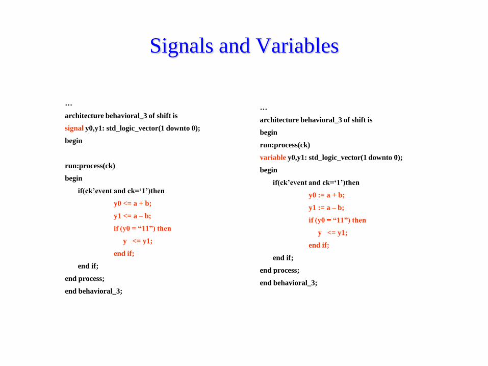
Signals and Variables
…
architecture behavioral_3 of shift is
begin
run:process(ck)
variable y0,y1: std_logic_vector(1 downto 0);
begin
if(ck‟event and ck=„1‟)then
y0 := a + b;
y1 := a – b;
if (y0 = “11”) then
y <= y1;
end if;
end if;
end process;
end behavioral_3;
…
architecture behavioral_3 of shift is
signal y0,y1: std_logic_vector(1 downto 0);
begin
run:process(ck)
begin
if(ck‟event and ck=„1‟)then
y0 <= a + b;
y1 <= a – b;
if (y0 = “11”) then
y <= y1;
end if;
end if;
end process;
end behavioral_3;
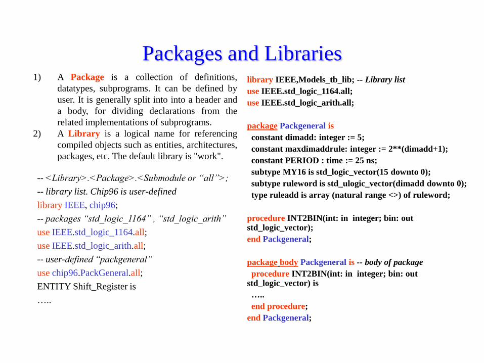
Packages and Libraries1) A Package is a collection of definitions,
datatypes, subprograms. It can be defined by
user. It is generally split into into a header and
a body, for dividing declarations from the
related implementations of subprograms.
2) A Library is a logical name for referencing
compiled objects such as entities, architectures,
packages, etc. The default library is "work".
-- <Library>.<Package>.<Submodule or “all”>;
-- library list. Chip96 is user-defined
library IEEE, chip96;
-- packages “std_logic_1164” , “std_logic_arith”
use IEEE.std_logic_1164.all;
use IEEE.std_logic_arith.all;
-- user-defined “packgeneral”
use chip96.PackGeneral.all;
ENTITY Shift_Register is
…..
library IEEE,Models_tb_lib; -- Library list
use IEEE.std_logic_1164.all;
use IEEE.std_logic_arith.all;
package Packgeneral is
constant dimadd: integer := 5;
constant maxdimaddrule: integer := 2**(dimadd+1);
constant PERIOD : time := 25 ns;
subtype MY16 is std_logic_vector(15 downto 0);
subtype ruleword is std_ulogic_vector(dimadd downto 0);
type ruleadd is array (natural range <>) of ruleword;
procedure INT2BIN(int: in integer; bin: out std_logic_vector);
end Packgeneral;
package body Packgeneral is -- body of package
procedure INT2BIN(int: in integer; bin: out std_logic_vector) is
…..
end procedure;
end Packgeneral;

Sequence of Compilation
- A hierarchical design have to be analysed from bottom to top
- ASCII scripts
Simulation Synthesis
Analysis

Testbench
DUT: Design Under testVHDL stimulus file Verification
Testbench
- Further top-level cell used for simulation. It only instantiates the
top-level cell of the design and its entity has no I/O signals
- The architecture can have processes and sub-modules
for stimuli generation
- Low Effort: fast response analysis of a few I/O patterns by
waveform inspection
- High Effort: requires even most of the time project. Statistical
analysis based on Automated Test Pattern Generation (ATPG)

Testbenchlibrary ieee,Models_tb_lib;
use ieee.std_logic_1164.all, ieee.std_logic_arith.all;
use ieee.std_logic_unsigned.all, Models_tb_lib.Packgeneral.all;
entity Minimum4 is
port( a,b,c,d: in my7; ck: in std_logic; theta: out my7);
end Minimum4;
architecture behavioral of Minimum4 is
begin
mini:process(ck)
variable temp1,temp2:my7;
begin
if(ck'event and ck=„1„)then
Example of stimuli generation for a circuit that
takes the minimum value among a, b, c, d. Here
is shown the module “minimum4” while next is
shown the testbench called “stimuli” that
instantiates “minimum4“ as DUT
Stimuli are also written in VHDL
if (a > b) then
temp1 := b;
else
temp1 := a;
end if;
if (c > d) then
temp2 := d;
else
temp2 := c;
end if;
if (temp1 > temp2) then
theta <= temp2;
else
theta <= temp1;
end if;
end if; -- ck closed
end process mini;
end behavioral;

TestbenchENTITY Test_Minimum4 IS
END Test_Minimum4;
LIBRARY ieee,Models_tb_lib; USE ieee.std_logic_1164.all;
USE ieee.std_logic_arith.all;
USE Models_tb_lib.packgeneral.all;
ARCHITECTURE stimulus OF Test_Minimum4 IS
COMPONENT Minimum4
port(a,b,c,d : IN my7; ck : IN std_logic; theta : out my7);
END COMPONENT;
SIGNAL a,b,c,d, theta : my7; SIGNAL ck : std_logic;
BEGIN
clock : process
begin
ck <= '0'; wait for PERIOD;
for i in 0 to 20 loop ck <= not(ck); wait for PERIOD; end loop;
wait; -- For avoiding endless loop
end process clock;
run : process
variable var_a,var_b,var_c,var_d: std_logic_vector(6 downto 0);
begin
for i in 50 to 60 loop int2bin(i,var_a); -- procedure in “packgeneral”
a <= var_a; int2bin(i+2,var_b); b <= var_b; int2bin(i+5,var_c);
c <= var_c; int2bin(2*i-50,var_d);
d <= var_d;
wait for 2*PERIOD;
end loop;
wait; -- For avoiding endless loop
end process run;
dut : Minimum4
PORT MAP (a,b,c,d,ck,theta);
end stimulus;

Aggregates
signal A : bit_vector (5 downto 0);
A <= ( 5 => `0`, 4 downto 2 => `1`, 1 => „0‟, others => `0`);
A <= (others => '0'); -- all bits set to „0‟
A <= (others => „1'); -- all bits set to „1‟

Concatenationsignal A : std_logic_vector (1 downto 0);
signal B : std_logic_vector (2 downto 0);
signal C : std_logic_vector (4 downto 0);
C <= A & B; -- allowed in right side only
-- data types must match in type and lenght
equivalent to
C(4) <= A(1);
C(3) <= A(0);
C(2) <= B(2);
C(1) <= B(1);
C(0) <= B(0);
A & B <= C; -- ERROR
C(4)
C(3)
C(2)
C(1)
C(0)
A(1)
A(0)
B(2)
B(1)
B(0)

Operators
Logical not, (and or nand nor xor xnor)
Relational (= /= < <= >= >)
Shift (sll srl sla sra rol ror)
Arithmetic (** abs), (mod rem), (* /), (+ -)
Precedence
- Ror(l) means rotation right (left) and no bit is lost
- Sr(l)r means shift right (left) logic and LSB (MSB) is lost.
The MSB (LSB) is then set to the default value
- Relationals are allowed also for non-homogeneous array
length. In this case the designer must add „0‟ as MSBs
signal A: std_logic_vector(2 downto 0);
signal B: std_logic_vector(4 downto 0);
if (( "00"& A) <= B) then
*, /
are synthesizable easily if the
operand is a power of 2
(truncation and „0‟ concatenation)
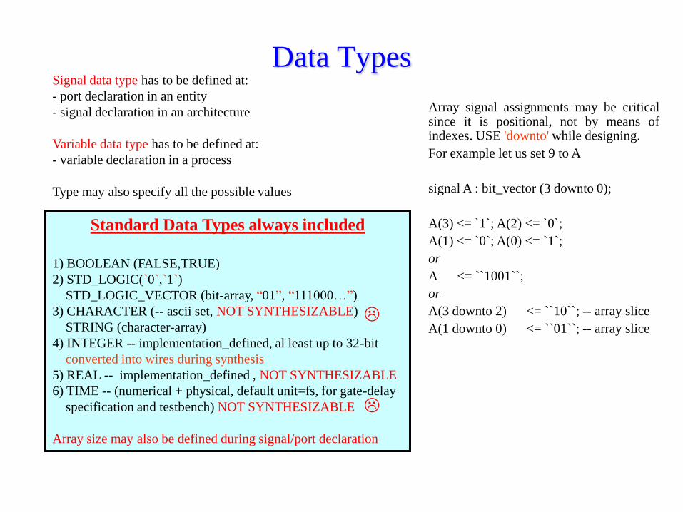
Data TypesSignal data type has to be defined at:
- port declaration in an entity
- signal declaration in an architecture
Variable data type has to be defined at:
- variable declaration in a process
Type may also specify all the possible values
Standard Data Types always included
1) BOOLEAN (FALSE,TRUE)
2) STD_LOGIC(`0`,`1`)
STD_LOGIC_VECTOR (bit-array, “01”, “111000…”)
3) CHARACTER (-- ascii set, NOT SYNTHESIZABLE)
STRING (character-array)
4) INTEGER -- implementation_defined, al least up to 32-bit
converted into wires during synthesis
5) REAL -- implementation_defined , NOT SYNTHESIZABLE
6) TIME -- (numerical + physical, default unit=fs, for gate-delay
specification and testbench) NOT SYNTHESIZABLE
Array size may also be defined during signal/port declaration
Array signal assignments may be criticalsince it is positional, not by means ofindexes. USE 'downto' while designing.
For example let us set 9 to A
signal A : bit_vector (3 downto 0);
A(3) <= `1`; A(2) <= `0`;
A(1) <= `0`; A(0) <= `1`;
or
A <= ``1001``;
or
A(3 downto 2) <= ``10``; -- array slice
A(1 downto 0) <= ``01``; -- array slice

Data TypesUsed-defined data type
1) Scalar: one value (integer, real, bit)
2) Array: read-write records
3) Others
type DATA is array (NATURAL range <>) of integer;
constant TEMP: DATA :=(2,3,5,2,3,2,3,1,2,3,9,6,2,3,4,5);
signal temp_signal is integer range 0 to 15;
….
running : process
begin
for k in 0 to 20 loop
temp_signal <= temp(k);
wait for 20 ns;
end loop;
wait;
end process;
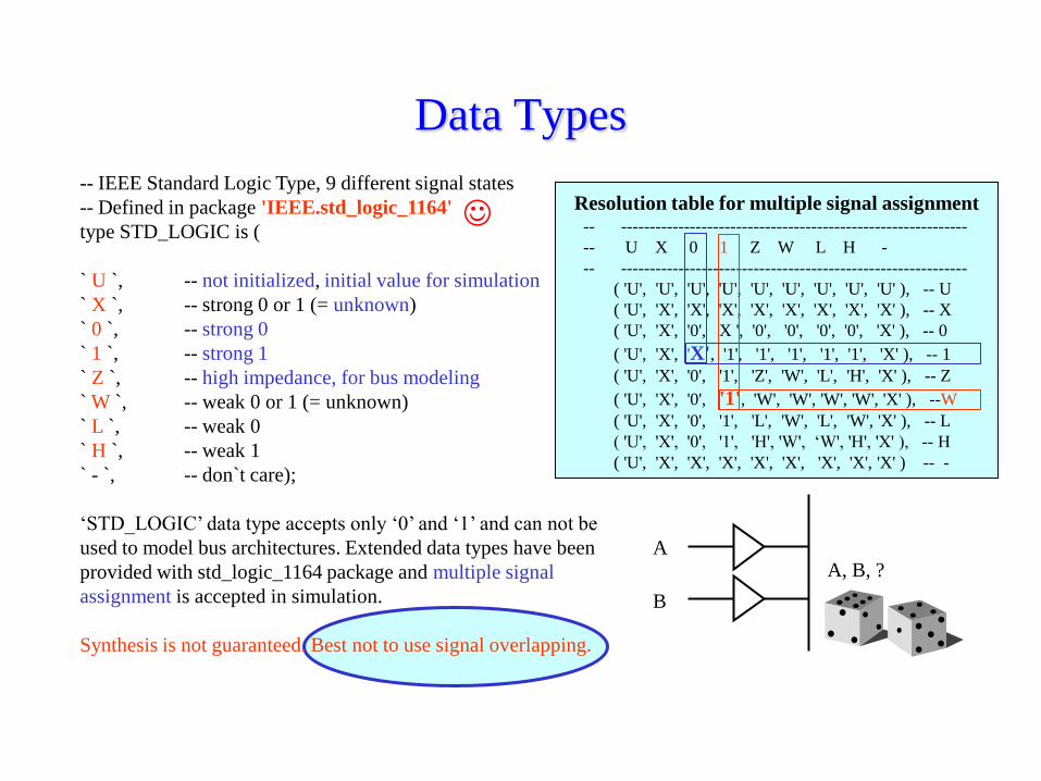
Data Types
-- IEEE Standard Logic Type, 9 different signal states
-- Defined in package 'IEEE.std_logic_1164'
type STD_LOGIC is (
` U `, -- not initialized, initial value for simulation
` X `, -- strong 0 or 1 (= unknown)
` 0 `, -- strong 0
` 1 `, -- strong 1
` Z `, -- high impedance, for bus modeling
` W `, -- weak 0 or 1 (= unknown)
` L `, -- weak 0
` H `, -- weak 1
` - `, -- don`t care);
„STD_LOGIC‟ data type accepts only „0‟ and „1‟ and can not be
used to model bus architectures. Extended data types have been
provided with std_logic_1164 package and multiple signal
assignment is accepted in simulation.
Synthesis is not guaranteed. Best not to use signal overlapping.
Resolution table for multiple signal assignment-- ------------------------------------------------------------
-- U X 0 1 Z W L H -
-- ------------------------------------------------------------
( 'U', 'U', 'U', 'U', 'U', 'U', 'U', 'U', 'U' ), -- U
( 'U', 'X', 'X', 'X', 'X', 'X', 'X', 'X', 'X' ), -- X
( 'U', 'X', '0', X ', '0', '0', '0', '0', 'X' ), -- 0
( 'U', 'X', 'X', '1', '1', '1', '1', '1', 'X' ), -- 1
( 'U', 'X', '0', '1', 'Z', 'W', 'L', 'H', 'X' ), -- Z
( 'U', 'X', '0', '1', 'W', 'W', 'W', 'W', 'X' ), --W
( 'U', 'X', '0', '1', 'L', 'W', 'L', 'W', 'X' ), -- L
( 'U', 'X', '0', '1', 'H', 'W', „W', 'H', 'X' ), -- H
( 'U', 'X', 'X', 'X', 'X', 'X', 'X', 'X', 'X' ) -- -
A
B
A, B, ?

Data Types1) STD_LOGIC instead of BIT and STD_LOGIC_VECTOR (allowed arithmetical operations onvectors) instead of BIT_VECTOR are recommended for RTL level designs: common industrystandard
2) NUMERIC_STD package is inside library IEEE and provides bit vector with signed andunsigned integer values. “to_integer” and “to_(un)signed” are package functions. Signed are 2-complement while unsigned are integer binary representations
3) Matrix are generally not synthesizable. Better not to use them.
4) Subtypes are reduced version of another type. For example MY28 is a subtype ofstd_logic_vector:
subtype MY28 is std_logic_vector(27 downto 0);

Esempio: macchina a stati
ARCHITECTURE behavioral of BCD_Selector is
type state_type is (zero, one, two, three, four, five);
signal current_state: state_type;
begin
RUN:PROCESS(ck, reset)
begin
if(reset=„1‟) then
current_state <= zero; Exit <= „0‟;
elsif(ck‟event and ck=„1‟) then
case current_state is
when zero =>
current_state <= one; Exit <= „0‟;
when one =>
if(enable=„0‟)then
current_state <= two;
else
current_state <= four;
end if;
Exit <= „0‟;
...

Esempio: algoritmo per la divisione
numeratore denominatore12 0
0
divtemp den
divtemp > densì
quoziente(i)=1
divtemp=divtemp-den
no
quoziente(i)=0
divtemp shiftato a sinistra
per i da 6 a 0

Entità del blocco Divisore
entity Divisore is
port( num: in my13;
den: in my6;
ck: in std_logic;
godiv: in std_logic;
zetaout:out my7);
end Divisore;
Divisore13
6num
dengodiv
ck
zetaout7

Architettura del blocco Divisore
architecture behavioral of Divisore is
signal num_temp: my13;
signal den_temp: my6;
begin
run0:process
begin
wait until ck' event and ck = '1';
if (godiv = '1') then
num_temp <= num;
den_temp <= den;
end if;
end process run0;
run1:process(num_temp,den_temp)
variable divtemp, divout: my7;
begin
divtemp := num_temp(12 downto 6);
for i in 0 to 5 loop
if(divtemp >= ('0' & den_temp))then
divout(6-i) := '1';
divtemp := divtemp-den_temp;
else
divout(6-i) := '0';
end if;
divtemp(6 downto 1):=divtemp(5 downto 0);
divtemp(0) := num_temp(5-i);
end loop;

Architettura del blocco Divisore:
continuaif(divtemp >= ('0' & den_temp))then
divout(0) := '1';divtemp := divtemp-den_temp;
elsedivout(0) := '0';divtemp(6 downto 1) :=
divtemp(5 downto 0);divtemp(0) := '0';
end if; --approssimazione del risultatoif(divtemp) >= ('0' & den_temp(5 downto
1)) thendivout := divout + "0000001";
end if;zetaout <= divout after 50 ns;
end process run1;end behavioral;
L‟uscita zetaout viene fornita dopo
50 ns dall‟inizio del processo di
divisione per modellare il
comportamento della rete circuitale
che impiegherà circa questo tempo
per svolgere il suo compito.
Il passo successivo consiste nel
verificare che dati due valori agli
ingressi num e den l‟uscita zetaout
corrisponda al valore effettivo
del quoziente.

Simulazione funzionale con Modelsim
Num = 500
Den = 48
Godiv = 1
dopo 50 ns
Zetaout = 10
(approssimazione
per difetto)
50 ns

Wait Statement1) The process stops and continues when the wait
statement is fulfilled
2) Wait statements are incompatible with sensitivity list
- wait for a specific time (Simulation only)
- wait for a signal event (Used in synchronous design)
- wait for a true condition (Event plus boolean condition)
One: process -- EVENT on CK
begin
wait on CK;
if (CK = '1') then – Rising Edge
Q <= D;
else
null;
end if;
end process;
Two: process
begin
--Rising Edge Event on CK
wait until CK‟event and CK=„1‟;
Q <= D;
end process;
Three: process
begin
wait until CK‟event;--- Edge Event on CK
Q <= D;
end process;
Four: process(CK) --- Best Used
begin
if(CK‟event and CK=„1‟)then--- Rising Edge Event on CK
Q <= D;
end if;
end process;
D Q
CK
Four: process(CK) --- Best Used
begin
if(rising_edge(CK)) then--- Rising Edge Event on CK
Q <= D;
end if;
end process;

Synchronous Process
D Q
CK
Reset
Run1: Process(Reset, Ck) – Asynchronous Flip-Flop
begin
-- wait until Ck‟event and Ck=„1‟;
if(Reset=„0‟)then -- checked first
Q <= „0‟;
elsif (Ck‟event and Ck=„1‟ ) then -- FPGAs and most other devices
Q <= D;
end if;
end process;
The „else‟ path is omitted, and not to be used, where
an event is modeled.

Synchronous Process: Pipeline-- Synchronous Flip-Flop (MOST USED)
Run2:Process(Ck)
begin
if (Ck‟event and Ck=„1‟) then
X <= A+B;
Y <= C+D;
Z <= X+Y;
end if;
end process;
-- Signal assignment carried out in two stages: PIPELINE!!
Time_ck_min Time_FFCKQ+ Time_COMBINATIONAL + T_FFSETUP
A, B,
C, D
X,YA+B
C+D
D Q
CK
D Q
CK
X+Y
CK
Multiple Flip-Flops
Z

×
×
×
× +
-
+
-
e
if
h
d
if
g
×
×
+
-
d
he
g
+
-
+
×
a
×
b
×
c
| A |
a b c
d e f
g h i
A =
Calculating the determinant of a 3x3 matrix

×
×
×
× +
-
+
-
e
if
h
d
if
g
×
×
+
-
d
he
g
+
-
+
×
a
×
b
×
c
| A |
D Q
D Q
D Q
D Q
D Q
D Q
D Q
D Q
D Q
D Q
D Q
D Q
D Q

×
×
×
× +
+
+
+
+
+×
+
+
D Q
×
×
+
+
+
+
D Q
Parallel Semi-
Parallel
Serial
Customize Architectures to Suit Your Ideal
Algorithms
FPGAs allow Area (cost) / Performance tradeoffs
Optimized for ?Speed Cost

Asynchronous Combinatorial Process
Multiplexer:process(a,b,c)
begin
if c = „0‟ then
y <= a;
else
y <= b;
end if;
end process;
b
a
c
y
To be used

Subprograms1) Functions (one return parameter)
2) Procedures
- Similar to subroutines in traditional languages
- Can have local variables like processes
- Generally used for testbenches and packages
…….
package body Packgeneral is
…….
PROCEDURE INT2BIN(
int: in integer;
bin: out std_logic_vector) is
variable tmp: integer;
begin
tmp := int;
for i in 0 to (bin'length - 1) loop
if (tmp MOD 2 = 1) then
bin(i) := '1';
else
bin(i) :='0';
end if;
tmp := tmp / 2;
end loop;
END INT2BIN;
…….
END Packgeneral;
procedure BIN2INT(bin: in std_logic_vector; int: out integer) is
variable result,pp: integer;
begin
pp := bin'length - 1;
result := 0;
for i in 0 to pp loop
if bin(i) = '1' then
result := result + 2**i;
end if;
end loop;
int := result;
end bin2int;
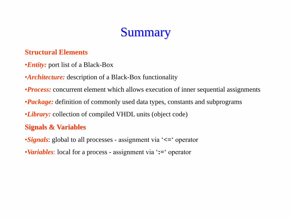
Summary
Structural Elements
•Entity: port list of a Black-Box
•Architecture: description of a Black-Box functionality
•Process: concurrent element which allows execution of inner sequential assignments
•Package: definition of commonly used data types, constants and subprograms
•Library: collection of compiled VHDL units (object code)
Signals & Variables
•Signals: global to all processes - assignment via „<=„ operator
•Variables: local for a process - assignment via „:=„ operator

Questions1) What is the variable assigment syntax?
2) What is the signal assigment syntax?
3) Where a variable can be defined and where can be used?
4) Where a signal can be defined and where can be used?
5) When a variable is assigned?
6) When a signal is assigned?
7) How many times a variable can be assigned in a process?
8) How many times a signal can be assigned in a process?
9) What is the limit of character data type?
10) Is the entity statement mandatory?
11) Is the architecture statement mandatory?
12) Is the library declaration mandatory?
13) What is a sensitivity list and when must not be used?
14) To which other statement a sensitivity list is incompatible?
15) Which end-values can assume a loop statement?

Find out the syntax errors and the non-sensesRUN:PROCESS
begin
if( ck'event and ck='1„)then;
sig0 <= data; sig1 <= sig0; exit <= sig1;
end if;
END PROCESS;
entity FULL is
port (A,B, Carry_In(3 downto 0): in std_logic;
Sum, Carry_Out(3 downto 0): in std_logic);
end FULL;
C(3) <= A(0);
C(2 downto 0) <= B(3 downto 1);
C (5 downto 3) <= B(1 downto 0);
C(0) <= B(0);
A & B <= C
Run1:Process(Ck)
begin
if(Reset=„0‟)then
Q <= “0”;
elsif (Ck‟event and Ck=„1‟ )then
Q <= D;
end if;
end process;
if(ck”event and ck=„1‟)then
y1 <= x0;
y0 <= x1;
y1 <= x2;
end if;