Embed Size (px)
Citation preview
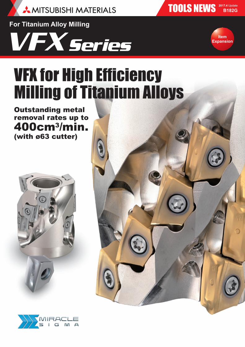
TOOLS NEWS
Outstanding metal removal rates up to400cm3/min.(with ø63 cutter)
VFX for High Effi ciency Milling of Titanium Alloys
B182G2017.4 Update
ItemExpansion
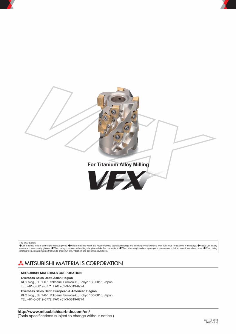
For Titanium Alloy Milling
VFXSeries

1
V Formation of theClamping Face
Coolant Discharge Position
Convex CurveCutting Edge
Cutting Force
Coolant Nozzle
Unparalleled Chip Ejection Properties Helps Re-defi ne the Parameters for Machining Titanium Alloy
VFXSeriesHigh Rigidity Design
Improved Chip Removal with Coolant
Highly Reliable Clamping Mechanism
Low Resistance Convex Curve Cutting Edge
Changeable Coolant Nozzle
Arranging the inserts vertically absorbs the principal cutting force through the thickness of the insert and achieves extremely high rigidity.
The internal coolant is directed slightly above the rake face of the cutting edge so that it is aimed directly at the chip. Forcibly ejecting the chips prevents them from welding to the cutting edge, enabling higher effi ciency machining.
The insert seat has a curved seating face in the radial direction of the tool and a V-shaped seating face on the axis of rotation that can securely handle cutting forces from any direction.
The curved cutting edge resembles the geometry of a solid end mill and achieves low cutting resistance and enables high quality machining.
A replaceable nozzle is used for the internal coolant (hole diameter of the standard nozzle supplied: ø0.8). The coolant pressure can be adjusted by using a nozzle with a smaller or larger diameter. Nozzles with different diameters are available as options.

2
LS MS HS
LS
MS
HS
DC×0.1 DC×0.3 DC×0.5 DC×0.7 DC×0.9
R0.8 R1.2R1.2 R1.6R1.6 R2.4R2.4 R3.2R3.2 R4.0R4.0 R5.0
R0.8 R1.2
R0.8 R1.2
ø40-80mm3,4,5,626-75mm
ø63-100mm4,5,631-90mmVFX5 VFX6
MP9030 uses an accumulated type coating based on a Ti compound that demonstrates excellent abrasion and fracture resistance during titanium alloy machining.
During high chip volume applications such as slotting, chip evacuation performance is important and if insuffi cient can lead to chipping of the insert.To solve this problem a 3 fl ute cutter with maximised main fl utes and chip pockets has been developed.Use of the new LS breaker in conjunction with the 3 fl ute cutter will maximise the performance benefi ts.
An new and enhanced super fi ne cemented carbide substrate has increased toughness whilst maintaining hardness.The Al-Ti-Cr-N accumulated type coating ensures optimum heat and wear resistance. The combination of these properties gives excellent fracture resistance and a very low coeffi cient of friction for class leading welding resistance when machining titanium alloy.
Produces compact chips without increases in cutting resistance. Excellent performance at large widths of cut and during slotting.
Covers a wide range of cutting conditions and applications.
Excellent chip separation and strong cutting edge. Highly effi cient machining is possible at small widths of cut.
Grade Width of Cut : ae
First RecommendedMP9130
General Purpose GradeMP9030
DiameterNumber of FlutesLength of Tooth
DiameterNumber of FlutesLength of Tooth
Grade:MP9130 MP9030Insert Type:MS
Grade:MP9130 MP9030Insert Type:MS
Grade:MP9130 MP9030Insert Type:HS
Grade:MP9130 MP9030Insert Type:HS
Grade:MP9130Insert Type:LS
Grade:MP9130Insert Type:LS
Sub Pocket
*Only the end cutting edge can be changed. On the peripheral cutting edges please use R1.2 for VFX6 and R0.8 for VFX5.
Selecting Inserts
Combination of Holder and Insert Corner R
Newly Developed 3-fl ute Holder (VFX5 Only)
3
L8
DCON
KWW
DC
DAH
APMX90°
LF
DCSF
MS
CBDP
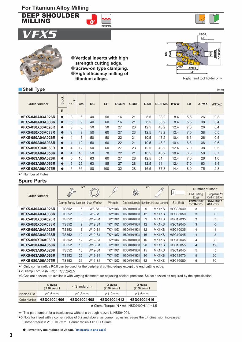
DC LF DCON CBDP DAH DCSFMS KWW L8 APMX WT(kg)
R
VFX5-040A03A026R a 3 6 40 50 16 21 8.5 38.2 8.4 5.6 26 0.3VFX5-040A03A038R a 3 9 40 60 16 21 8.5 38.2 8.4 5.6 38 0.4VFX5-050X03A026R a 3 6 50 50 27 23 12.5 48.2 12.4 7.0 26 0.4VFX5-050X03A038R a 3 9 50 60 27 23 12.5 48.2 12.4 7.0 38 0.5VFX5-050A04A026R a 4 8 50 50 22 21 10.5 48.2 10.4 6.3 26 0.5VFX5-050A04A038R a 4 12 50 60 22 21 10.5 48.2 10.4 6.3 38 0.6VFX5-050X04A038R a 4 12 50 60 27 23 12.5 48.2 12.4 7.0 38 0.5VFX5-050A04A050R a 4 16 50 70 22 21 10.5 48.2 10.4 6.3 50 0.7VFX5-063A05A026R a 5 10 63 60 27 28 12.5 61 12.4 7.0 26 1.0VFX5-063A05A063R a 5 25 63 85 27 28 12.5 61 12.4 7.0 63 1.4VFX5-080A06A075R a 6 36 80 100 32 28 16.5 77.3 14.4 8.0 75 2.8
*2 *3
*1
XNMU1607ooR-oo
XNMU160708R-oo
VFX5-040A03A026R TS352 6 W8-S1 TKY10D HSD04004H08 9 MK1KS HSC08040 3 3
VFX5-040A03A038R TS352 9 W8-S1 TKY10D HSD04004H08 12 MK1KS HSC08050 3 6
VFX5-050X03A026R TS352 6 W12-S1 TKY10D HSD04004H08 9 MK1KS HSC12035 3 3
VFX5-050X03A038R TS352 9 W12-S1 TKY10D HSD04004H08 12 MK1KS HSC12045 3 6
VFX5-050A04A026R TS352 8 W10-S1 TKY10D HSD04004H08 12 MK1KS HSC10035 4 4
VFX5-050A04A038R TS352 12 W10-S1 TKY10D HSD04004H08 16 MK1KS HSC10045 4 8
VFX5-050X04A038R TS352 12 W12-S1 TKY10D HSD04004H08 16 MK1KS HSC12045 4 8
VFX5-050A04A050R TS352 16 W10-S1 TKY10D HSD04004H08 20 MK1KS HSC10055 4 12
VFX5-063A05A026R TS352 10 W12-S1 TKY10D HSD04004H08 15 MK1KS HSC12045 5 5
VFX5-063A05A063R TS352 25 W12-S1 TKY10D HSD04004H08 30 MK1KS HSC12070 5 20
VFX5-080A06A075R TS352 36 W16-S1 TKY10D HSD04004H08 42 MK1KS HSC16080 6 30
ø0.6mm ø0.8mm ø1.2mm ø1.6mmHSD04004H06 HSD04004H08 HSD04004H12 HSD04004H16
y
VFX5
(mm)
For Titanium Alloy Milling
a : Inventory maintained in Japan. (10 inserts in one case)
Shell Type
*1 Only corner radius R0.8 can be used for the peripheral cutting edges except the end cutting edge.
*2 Clamp Torque (N • m) : TS352=2.5
*3 Coolant nozzles are available with varying diameters for adjusting coolant pressure. Select nozzles as required by the specifi cation.
Right hand tool holder only.
* Clamp Torque (N • m) : HSD0400Hpp=1.5
*4 The part number for a blank screw without a through nozzle is HSS04004.
*5 Note for insert with a corner radius of 3.2 and above, as corner radius increases the LF dimension increases.Corner radius 3.2: LF+0.7mm Corner radius 4.0: LF+1.5mm
<1Mpa(<20 l/min.) ←Standard→ >5Mpa
(>30 l/min.)>7Mpa
(>50 l/min.)
Nozzle Dia.
Order Number
Roughing
Vertical inserts with high strength cutting edge.Screw-on type clamping.High effi ciency milling of titanium alloys.
a
a
a
DEEP SHOULDER MILLING
*1 Number of Flutes
Spare Parts
Order Number Sto
ck
No.F Total
Order Number
Number of InsertEnd Cutting
EdgePeripheralCutting Edge
Clamp Screw Number Seal Washer Wrench Coolant Nozzle Number Anti-seize Lubricant Set Bolt
*
4
LE
LE
D1
D1
D1
L
L
W1
W1
SS
BS
BS
RE
RE
INSL
INSL
LE
L
W1 S
BS
RE
INSL
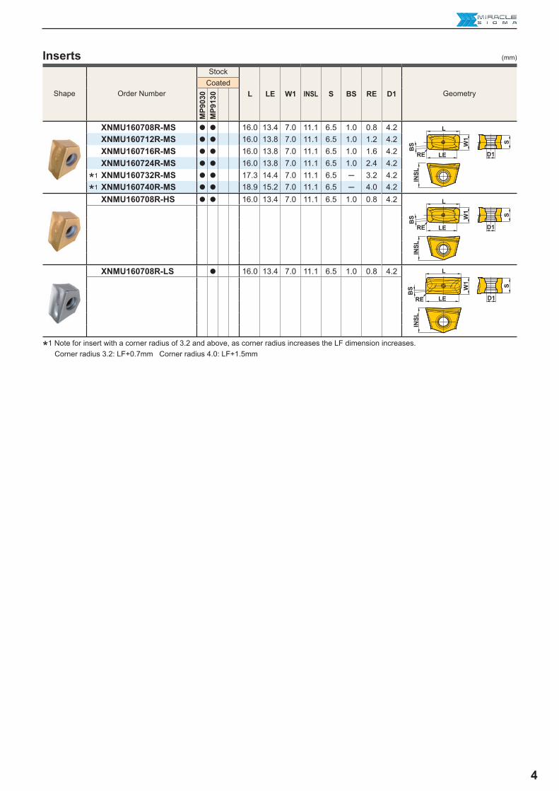
L LE W1 INSL S BS RE D1
MP9
030
MP9
130
XNMU160708R-MS a a 16.0 13.4 7.0 11.1 6.5 1.0 0.8 4.2 XNMU160712R-MS a a 16.0 13.8 7.0 11.1 6.5 1.0 1.2 4.2 XNMU160716R-MS a a 16.0 13.8 7.0 11.1 6.5 1.0 1.6 4.2 XNMU160724R-MS a a 16.0 13.8 7.0 11.1 6.5 1.0 2.4 4.2 XNMU160732R-MS a a 17.3 14.4 7.0 11.1 6.5 ─ 3.2 4.2 XNMU160740R-MS a a 18.9 15.2 7.0 11.1 6.5 ─ 4.0 4.2 XNMU160708R-HS a a 16.0 13.4 7.0 11.1 6.5 1.0 0.8 4.2
XNMU160708R-LS a 16.0 13.4 7.0 11.1 6.5 1.0 0.8 4.2
*1*1
(mm)Inserts
*1 Note for insert with a corner radius of 3.2 and above, as corner radius increases the LF dimension increases.Corner radius 3.2: LF+0.7mm Corner radius 4.0: LF+1.5mm
Shape Order Number
Stock
GeometryCoated
5
yVFX5
(kW) (Nm) (%)S
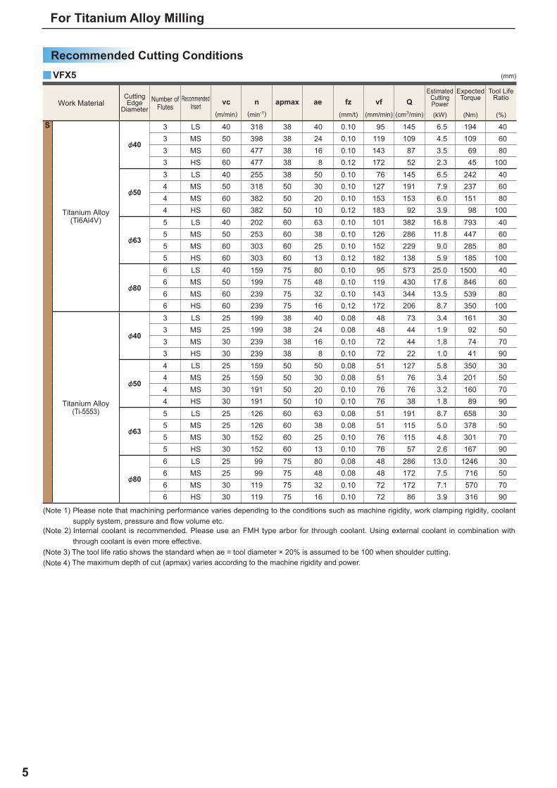
&40
3 LS 40 318 38 40 0.10 95 145 6.5 194 403 MS 50 398 38 24 0.10 119 109 4.5 109 603 MS 60 477 38 16 0.10 143 87 3.5 69 803 HS 60 477 38 8 0.12 172 52 2.3 45 100
&50
3 LS 40 255 38 50 0.10 76 145 6.5 242 404 MS 50 318 50 30 0.10 127 191 7.9 237 604 MS 60 382 50 20 0.10 153 153 6.0 151 804 HS 60 382 50 10 0.12 183 92 3.9 98 100
&63
5 LS 40 202 60 63 0.10 101 382 16.8 793 405 MS 50 253 60 38 0.10 126 286 11.8 447 605 MS 60 303 60 25 0.10 152 229 9.0 285 805 HS 60 303 60 13 0.12 182 138 5.9 185 100
&80
6 LS 40 159 75 80 0.10 95 573 25.0 1500 406 MS 50 199 75 48 0.10 119 430 17.6 846 606 MS 60 239 75 32 0.10 143 344 13.5 539 806 HS 60 239 75 16 0.12 172 206 8.7 350 100
&40
3 LS 25 199 38 40 0.08 48 73 3.4 161 303 MS 25 199 38 24 0.08 48 44 1.9 92 503 MS 30 239 38 16 0.10 72 44 1.8 74 703 HS 30 239 38 8 0.10 72 22 1.0 41 90
&50
4 LS 25 159 50 50 0.08 51 127 5.8 350 304 MS 25 159 50 30 0.08 51 76 3.4 201 504 MS 30 191 50 20 0.10 76 76 3.2 160 704 HS 30 191 50 10 0.10 76 38 1.8 89 90
&63
5 LS 25 126 60 63 0.08 51 191 8.7 658 305 MS 25 126 60 38 0.08 51 115 5.0 378 505 MS 30 152 60 25 0.10 76 115 4.8 301 705 HS 30 152 60 13 0.10 76 57 2.6 167 90
&80
6 LS 25 99 75 80 0.08 48 286 13.0 1246 306 MS 25 99 75 48 0.08 48 172 7.5 716 506 MS 30 119 75 32 0.10 72 172 7.1 570 706 HS 30 119 75 16 0.10 72 86 3.9 316 90
(mm)
For Titanium Alloy Milling
Recommended Cutting Conditions
(Note 1) Please note that machining performance varies depending to the conditions such as machine rigidity, work clamping rigidity, coolant supply system, pressure and fl ow volume etc.
(Note 2) Internal coolant is recommended. Please use an FMH type arbor for through coolant. Using external coolant in combination with through coolant is even more effective.
(Note 3) The tool life ratio shows the standard when ae = tool diameter × 20% is assumed to be 100 when shoulder cutting.(Note 4) The maximum depth of cut (apmax) varies according to the machine rigidity and power.
Work MaterialCutting Edge
DiameterNumber of
FlutesRecommended
Insert vc(m/min)
n(min-1)
apmax ae fz(mm/t)
vf(mm/min)
Q(cm3/min)
Estimated CuttingPower
Expected Torque
Tool Life Ratio
Titanium Alloy(Ti6Al4V)
Titanium Alloy(Ti-5553)

6
L8
DCON
KWW
DC
DAH
APMX90°
LF
DCSF
MS
CBDP
ø0.6mm ø0.8mm ø1.2mm ø1.6mmHSD04004H06 HSD04004H08 HSD04004H12 HSD04004H16
VFX6
DC LF DCON CBDP DAH DCSFMS KWW L8 APMX WT(kg)
R
VFX6-063A04A031R a 4 8 63 60 27 28 12.5 61 12.4 7 31 0.9VFX6-063A04A060R a 4 16 63 85 27 28 12.5 61 12.4 7 60 1.3VFX6-080A05A031R a 5 10 80 60 32 28 16.5 77.3 14.4 8 31 1.5VFX6-080A05A075R a 5 25 80 100 32 28 16.5 77.3 14.4 8 75 2.6VFX6-100A06A031R a 6 12 100 65 40 30 20.5 96.6 16.4 9 31 2.7VFX6-100A06A090R a 6 36 100 115 40 30 20.5 96.6 16.4 9 90 4.8
*2 *3
*1
XNMU1909ooR-oo
XNMU190912R-oo
VFX6-063A04A031R TS450 8 W12-S1 TKY20T HSD04004H08 12 MK1KS HSC12045 4 4VFX6-063A04A060R TS450 16 W12-S1 TKY20T HSD04004H08 20 MK1KS HSC12070 4 12VFX6-080A05A031R TS450 10 W16-S1 TKY20T HSD04004H08 15 MK1KS HSC16040 5 5VFX6-080A05A075R TS450 25 W16-S1 TKY20T HSD04004H08 30 MK1KS HSC16080 5 20VFX6-100A06A031R TS450 12 W20-S1 TKY20T HSD04004H08 18 MK1KS HSC20040 6 6VFX6-100A06A090R TS450 36 W20-S1 TKY20T HSD04004H08 42 MK1KS HSC20090 6 30
y (mm)
*1 Only corner radius R1.2 can be used for the peripheral cutting edges except the end cutting edge.
*2 Clamp Torque (N • m) : TS450=5.0
*3 Coolant nozzles are available with varying diameters for adjusting coolant pressure. Select nozzles as required by the specifi cation.
* Clamp Torque (N • m) : HSD0400Hpp=1.5
*4 The part number for a blank screw without a through nozzle is HSS04004.
*5 Note for insert with a corner radius of 3.2 and above, as corner radius increases the LF dimension increases.Corner radius 3.2: LF+0.7mm Corner radius 4.0: LF+1.5mm Corner radius 5.0: LF+1.5mm
<1Mpa(<20 l/min.) ←Standard→ >5Mpa
(>30 l/min.)>7Mpa
(>50 l/min.)
Nozzle Dia.
Order Number
Shell Type
Right hand tool holder only.
Roughing
DEEP SHOULDER MILLING
Vertical inserts with high strength cutting edge.Screw-on type clamping.High effi ciency milling of titanium alloys.
a
a
a
Spare Parts
Order Number Sto
ck
No.F Total
Order Number
Number of InsertEnd Cutting
EdgePeripheralCutting Edge
Clamp Screw Number Seal Washer Wrench Coolant Nozzle Number Anti-seize Lubricant Set Bolt
a : Inventory maintained in Japan.
*1 Number of Flutes
*
7
LE
LE
D1
D1
L
L
W1
W1
SS
BS
BS
RE
RE
INSL
INSL
D1LE
L
W1 S
BS
RE
INSL
L LE W1 INSL S BS RE D1
MP9
030
MP9
130
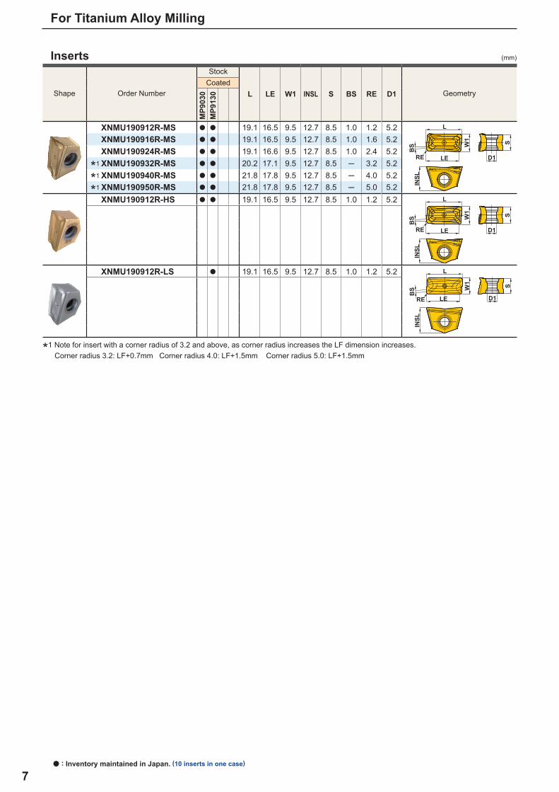
XNMU190912R-MS a a 19.1 16.5 9.5 12.7 8.5 1.0 1.2 5.2 XNMU190916R-MS a a 19.1 16.5 9.5 12.7 8.5 1.0 1.6 5.2 XNMU190924R-MS a a 19.1 16.6 9.5 12.7 8.5 1.0 2.4 5.2 XNMU190932R-MS a a 20.2 17.1 9.5 12.7 8.5 ─ 3.2 5.2 XNMU190940R-MS a a 21.8 17.8 9.5 12.7 8.5 ─ 4.0 5.2 XNMU190950R-MS a a 21.8 17.8 9.5 12.7 8.5 ─ 5.0 5.2 XNMU190912R-HS a a 19.1 16.5 9.5 12.7 8.5 1.0 1.2 5.2
XNMU190912R-LS a 19.1 16.5 9.5 12.7 8.5 1.0 1.2 5.2
*1
*1
*1
(mm)
For Titanium Alloy Milling
a : Inventory maintained in Japan. (10 inserts in one case)
*1 Note for insert with a corner radius of 3.2 and above, as corner radius increases the LF dimension increases.Corner radius 3.2: LF+0.7mm Corner radius 4.0: LF+1.5mm Corner radius 5.0: LF+1.5mm
Shape Order Number
Stock
GeometryCoated
Inserts
8
(kW) (Nm) (%)
S
&63
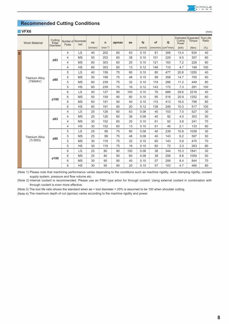
4 LS 40 202 60 63 0.10 81 306 13.4 634 404 MS 50 253 60 38 0.10 101 229 9.5 357 604 MS 60 303 60 25 0.10 121 183 7.2 228 804 HS 60 303 60 13 0.12 146 110 4.7 148 100
&80
5 LS 40 159 75 80 0.10 80 477 20.8 1250 405 MS 50 199 75 48 0.10 99 358 14.7 705 605 MS 60 239 75 32 0.10 119 286 11.2 449 805 HS 60 239 75 16 0.12 143 172 7.3 291 100
&100
6 LS 40 127 90 100 0.10 76 688 29.6 2218 406 MS 50 159 90 60 0.10 95 516 20.9 1252 606 MS 60 191 90 40 0.10 115 413 16.0 798 806 HS 60 191 90 20 0.12 138 248 10.3 517 100
&63
4 LS 25 126 60 63 0.08 40 153 7.0 527 304 MS 25 126 60 38 0.08 40 92 4.0 303 504 MS 30 152 60 25 0.10 61 92 3.8 241 704 HS 30 152 60 13 0.10 61 46 2.1 133 80
&80
5 LS 25 99 75 80 0.08 40 239 10.8 1038 305 MS 25 99 75 48 0.08 40 143 6.2 597 505 MS 30 119 75 32 0.10 60 143 5.9 475 705 HS 30 119 75 16 0.10 60 72 3.3 263 80
&100
6 LS 25 80 90 100 0.08 38 344 15.3 1841 306 MS 25 80 90 60 0.08 38 206 8.8 1059 506 MS 30 95 90 40 0.10 57 206 8.4 844 706 HS 30 95 90 20 0.10 57 103 4.7 466 80
yVFX6 (mm)
(Note 1) Please note that machining performance varies depending to the conditions such as machine rigidity, work clamping rigidity, coolant supply system, pressure and fl ow volume etc.
(Note 2) Internal coolant is recommended. Please use an FMH type arbor for through coolant. Using external coolant in combination with through coolant is even more effective.
(Note 3) The tool life ratio shows the standard when ae = tool diameter × 20% is assumed to be 100 when shoulder cutting.(Note 4) The maximum depth of cut (apmax) varies according to the machine rigidity and power.
Work MaterialCutting Edge
DiameterNumber of
FlutesRecommended
Insert vc(m/min)
n(min-1)
apmax ae fz(mm/t)
vf(mm/min)
Q(cm3/min)
Estimated CuttingPower
Expected Torque
Tool Life Ratio
Titanium Alloy(Ti6Al4V)
Titanium Alloy(Ti-5553)
Recommended Cutting Conditions

9
VFX6-080A05A075R VFX6-063A04A060R VFX6-063A04A060R
32.5 55 45
25 278 227
0.04 0.12 0.05
10-30 10-45 12-37
30-60 25-60 5-24
VFX5-050A04A050R VFX5-050A04A050R VFX5-050A04A050R
40 50 55
102 127 140
0.10 0.1 0.1
5-30 50 35
5-60 10 15
For Titanium Alloy Milling
aWith reference to the above examples, adjust the cutting conditions according to the machine specifi cations, workpiece geometry and clamping method used.
Application Examples
Tool
Workpiece
Titanium Alloy (Ti-5553) Titanium Alloy (Ti6Al4V) Titanium Alloy (Ti6Al4V)
Component Aerospace Parts Aerospace Parts Aerospace Parts
Cut
ting
Con
ditio
ns Cutting Speed (m/min)
Table Feed (mm/min)
Feed per Tooth (mm/t.)
Depth of Cut ae (mm)
Depth of Cut ap (mm)
Cutting Mode Wet Cutting (Internal:7MPa) Wet Cutting (Internal:10MPa) Wet Cutting (External:1.5MPa)
Results
With the same tool life (190 mins) as conventional tools, it was possible to use 1.2 times increased cutting conditions for greater effi ciency.
At a metal removal rate of 120cm3 /min, tool life was constant at 60mins and effi ciency increased x 1.5. VFX was stable in tests at a max. metal removal rate of 400cm3 /min.
Three times tool life at cutting conditions improved by a factor of 2.7. Total cost reductions of 62%.
Tool
Workpiece
Titanium Alloy (Ti6Al4V) Titanium Alloy (Ti6Al4V) Titanium Alloy (Ti6Al4V)
Component Aerospace Parts Aerospace Parts Aerospace Parts
Cut
ting
Con
ditio
ns Cutting Speed (m/min)
Table Feed (mm/min)
Feed per Tooth (mm/t.)
Depth of Cut ae (mm)
Depth of Cut ap (mm)
Cutting Mode Wet Cutting (Internal:3MPa) Wet Cutting (External:1.5MPa) Wet Cutting (External:3MPa)
Results
Effi ciency was increased by a factor of 1.3.
Effi ciency increased by a factor of 1.5 and was also possible to achieve stable machining of thin walled parts.
It was possible to use 2 times increased cutting conditions for greater cost reduction.

10
Memo
VFXXVFX
MITSUBISHI MATERIALS CORPORATION
Overseas Sales Dept, Asian RegionKFC bldg., 8F, 1-6-1 Yokoami, Sumida-ku, Tokyo 130-0015, JapanTEL +81-3-5819-8771 FAX +81-3-5819-8774
Overseas Sales Dept, European & American RegionKFC bldg., 8F, 1-6-1 Yokoami, Sumida-ku, Tokyo 130-0015, JapanTEL +81-3-5819-8772 FAX +81-3-5819-8774
2017.4.( - )EXP-10-E016
For Your SafetyaDon't handle inserts and chips without gloves. aPlease machine within the recommended application range and exchange expired tools with new ones in advance of breakage. aPlease use safety covers and wear safety glasses. aWhen using compounded cutting oils, please take fire precautions. aWhen attaching inserts or spare parts, please use only the correct wrench or driver. aWhen using rotating tools, please make a trial run to check run-out, vibration and abnormal sounds etc.
http://www.mitsubishicarbide.com/en/(Tools specifications subject to change without notice.)
For Titanium Alloy Milling