Embed Size (px)
Citation preview
VFD Applications:
User Manual
High Performance AC Drives
www.selec.comSelec Subsidiaries: www.selecusa.com | www.selec-europe.com | www.selecaustralia.comSelec USA: Selec GmbH: Selec Australia:
Selec Controls Pvt. Ltd.EL-27-1, Electronic Zone, TTC Industrial Area, MIDC, Mahape, Navi Mumbai 400710, INDIA.
Tel.:+91-22-4141 8468 / 452. Fax: +91-22-41418 408. Email: [email protected] | www.selec.com
Centrifuges Conveyors Winch Coal Machine Heading machine
Dock cranesOil Pumps Kilns Mine liftOffshore
Mine conveyor Tower crane Propulsion Roller tables Ski lifts
www.selec.com
User Manual Preface
To give full play to its function and ensure the safety of both users and
product, please read this manual carefully before using it. Any incorrect
operations may lead to fault, malfunction or shortened lifetime, even damage
of device and accident casualty.
This manual can provide you with the detailed rules and precautions,
including installation, wiring, the setting of functional parameter, daily
maintenance, malfunction diagnosis and solution etc.
This manual is enclosed randomly as an attachment, please keep it
safe in case that you need it for the inspection or maintenance of this product.
Any information in this manual is subject to change without notice in
accordance with our policy of continuous improvement of product.
• Please pay attention to the following points when using it:
• Power must be shut off before wiring.
• Ground wire must be connected correctly.
• In any case, AC power lines can't be connected to the output
terminals, such as U, V or W .
• Do not conduct the Withstand Voltage Test on the internal
components.
• No permission is granted to change or modify the internal components
or circuits.
• Only the qualified electronic engineer is allowed to assemble, wire,
repair or maintain the converter.
• Do not conduct the procedure of inspection or maintenance until
converter has been shut down for more than 3 minutes.
• Converter must be installed in a appropriate operating environment
and far away from humidity or water drops; care must be taken to prevent it from direct sunlight or being overheated.
• Do not touch the internal components for safety.
PREFACE
1www.selec.com
User ManualUser Manual
www.selec.com
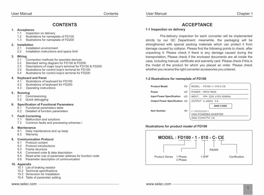
MODEL : FD100–1– 010-C-CE
POWER : 1HP/0.75KW
INPUT : 1PH 220V ±15% 50/60Hz
OUTPUT : 0–400Hz 5 A
1 1 5 0 5 0 0 0 1HIGH POWERED INVERTER
Selec Control Pvt. Ltd
BAR CODE
Product Model
Power
Output Power Specification
Input Power Specification
Item Number
1-1 Inspection on delivery
Pre-delivery inspection for each converter will be implemented
strictly by our QC Department; meanwhile, the packaging will be
strengthened with special packing materials which can protect it from
damage caused by collision. Please find the following points to check. after
unpacking it: Please check if there is any damage caused during the
transportation; Please check if the enclosed documents are all inside the
case, including manual, certificate and warranty card. Please check if this is
the model of the product for which you placed an order. Please check
whether you receive the right converter accessories you ordered.
1-2 Illustrations for nameplate of FD100
Illustrations for product model of FD100
Chapter 1
ACCEPTANCE
MODEL : FD100 - 1 - 010 - C- CE
Product Series 1 Phase3 Phase
1.0HP
RS485
Certification
2. Installation 2.1 Installation environment 2.2 Installation instructions and space limit
5 . Running 5.1 Commissioning 5.2 Quick debugging
9. Communication Protocol 9.1 Protocol content 9.2 Protocol introductions 9.3 Frame structure 9.4 Command code & data description 9.5 Read-write rule of parameter address for function code 9.6 Parameter description of communication
1. Acceptance 1.1 Inspection on delivery 1.2 Illustrations for nameplate of FD100 1.3 Illustrations for nameplate of FD200
3. Wiring 3.1 Connection methods for assorted devices 3.2 Standard wiring diagram for FD100 & FD200 3.3 Descriptions of major loop's terminal for FD100 & FD200 3.4 Illustrations for control loop's terminal for FD100 3.5 Illustrations for control loop's terminal for FD200
4. Keyboard and Panel 4.1 I llustrations of keyboard for FD100 4.2 Illustrations of keyboard for FD200 4.3 Operating instructions
6. Specification of Functional Parameters 6.1 Functional parameters table 6.2 Detailed of function parameters
7. Fault Correcting 7.1 Malfunction and solutions 7.2 Common faults and processing schemes \
8. Maintenance 8.1 Daily maintenance and up keep 8.2 Warranty
10. Appendix 10.1 List of braking resistor 10.2 Technical specifications 10.3 Dimension for Installation 10.4 Table of parameter setting
CONTENTS
Contents

3www.selec.com
User ManualUser Manual
www.selec.com2
Chapter 1 Chapter 2
INSTALLATION 2-1 Installation environment
• No Water drops, steam, dust or oily dust surrounded.
• Solid base without vibration.
• Ambient temperature should be -10°C ~ +40°C; in case that the ambient temperature is higher than 40°C and that it is overheated, it should be stored in a place where there is good ventilation.
• No caustic or inflammable gas and liquid surrounded.
• No electromagnetic or noise interference.
• No floating dust and metal particles surrounded.
2-2 Installation instructions and space limit
• It should be installed on the fire-proof frame, for example metal frame, in case that it causes fire accidents.
• It should be mounted by screws vertically; upside-down, slant or horizontal mounting are not allowed.
• Spare space must be ensured for the ventilation of converter in case that it's overheated while it's running.
• To minimize the heat effect on each other, they should be horizontally installed abreast if two or more converters are installed in the same control cabinet; Baffle plate must be set up between them for the same reason if they have to be installed vertically.
• Ventilation must be taken into consideration to ensure that ambient temperature is lower than specified value when converter is installed inside a control cabinet.
• It should be kept away from various impurity, such as fiber, paper scraps, wood chips or metal filings up.
50mm 50mm
≥100mm
≥100mm
UP
RightCONVERTER
CONVERTER
CONVERTER
MODEL : FD200–3–100-C-CE
POWER : 10HP/7.5KW
INPUT : 10PH 415V ±15% 50/60Hz
OUTPUT : 0–400Hz 17 A
0 1 9 0 5 9 0 3 7HIGH POWERED INVERTER
Selec Control Pvt. Ltd
BAR CODE
Product Model
Power
Output Power Specification
Input Power Specification
Item Number
1-3 Illustrations for nameplate of FD 200
Illustrations for product model of FD200
MODEL : FD200 - 3 - 100 - C- CE
Product Series 3 Phase 10.0HP
RS485
Certification
5www.selec.com
User ManualUser Manual
www.selec.com4
Chapter 3 Chapter 3
3-2A Standard wiring diagram for FD100
Braking resistor
QFMC
R/L
S
T/N T
S
R
B1 B2
U
W
V
PE
M
FWD
External fault
REV
Multi-phasereference velocity 1
Common terminal
X1 Input terminal 1
X2 Input terminal 2
X3 Input terminal 3
X4 Input terminal 4
COM
PE
COM
X5 Input terminal 5CN1
Preset frequency 0-10V
0-10V Input
0-20VmA Input
Potentio-meter3-5K
+10V Frequency setting
AI1 Multi-functional AI1
AI2 Jumper 3
GND
PE
0-20mAAI20-10V
Jumper 4
0-20mAAO
0-10V
AO
GND
AO
Default setting:
operating frequency
0-40V/0-20mA
1 5V
485+
485-
GND
485 communication
+24V
port
Y1
8
Default setting:
Run command
ROA
ROB
ROC
Default setting:
Fault output
Output of relay
BR
Converter
One-phase 220V power supplyfrom LN input terminalThree-phase power source220V/415V50/60Hz
Default setting
RY1
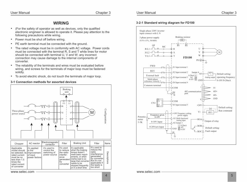
WIRING
• Power must be shut off before wiring.
• The rated voltage must be in conformity with AC voltage. Power cords must be connected with the terminal R, S and T while lines for motor should be connected with terminal U, V and W; any incorrect connection may cause damage to the internal components of converter.
• To avoid electric shock, do not touch the terminals of major loop.
• (For the safety of operator as well as devices, only the qualified electronic engineer is allowed to operate it. Please pay attention to the following precautions while wiring.
• PE earth terminal must be connected with the ground.
• The reliability of the terminals and wires must be evaluated before wiring, and screws for the terminals of major loop must be fastened solidly.
3-1 Connection methods for assorted devices
Chopper
AC reactor
Electromagneticcontactor
Filter
Braking Unit
Filter
Name
Applicable model should be selected; its rated current must be no less than 1.5 times the ratedcurrent of converter.
It is applied to the improvement of input power factors.
It is used to control the switching of powersource
It is used to reduce the radio interferencegenerated by converter.
It is applicable when the braking torque doesn’t meetbasic requirements, or when inertia load is so largethat converter needs to be stopped frequently or in ashort time.
It is used to reduce the radio interferencegenerated by converter. But it’s not applicable ifthe leads is too short.
Descriptions
.
Con
figuration
Three-phase power source
Brakingunit
(+) (-)
R U
S V
T W
M
Chopper AC reactor Electromagneticcontactor Filter Braking Unit Filter Name
Applicablemodel shouldbe selected; itsrated currentmust be noless than 1.5times therated currentof converter
it’s appliedto the improvement of inputpower factors
it’s used to control the switching ofpower source
it’s usedto reducethe radio interfer-ence generatedbyconverter
it’s applicablewhen the brakingtorque doesn’tmeet basic requir-ements, or wheninertia load is solarge that converterneeds to bestopped frequentlyor in a short time
It’s used to reduce the radiointerference generatedby converter.But it’s not applicable ifthe leads istoo short
Descrip
tions
Configuration
Three-phase power source
Brakingunit
(+) (-)
R U
S V
T W
M
3-2-1 Standard wiring diagram for FD100
Braking resistor
QFMC
R/L
S
T/N T
S
R
B1 B2
U
W
V
PE
M
FWD
External fault
REV
Multi-phasereference velocity 1
Common terminal
X1 Input terminal 1
X2 Input terminal 2
X3 Input terminal 3
X4 Input terminal 4
COM
PE
COM
X5 Input terminal 5CN1
Preset frequency
0-10V Input
0-20VmA Input
Potentio-meter3-5K
+10V Frequency setting
AI1 Multi-functional AI1
AI2 Jumper 3
GND
PE
0-20mAAI20-10V
Jumper 4
0-20mAAO
0-10V
AO
GND
AO
Default setting:
operating frequency
0-10V/0-20mA
1 5V
485+
485-
GND
485 communication
J5
+24V
port
Y1
8
Default setting:
Run command
ROA
ROB
ROC
Default setting:
Fault output
Output of relay
VFD200
BR
RY1
3 phase power supply
Single phase 220V inverterinput connect with L N
415V±15%, 50/60Hz
Braking resistor
QFMC
R/L1
S/L2
T/L3 T
S
R
B1 B2
U
W
V
PE
M
FWD
External fault
REV
Multi-phasereference velocity 1
Common terminal
X1 Input terminal 1
X2 Input terminal 2
X3 Input terminal 3
X4 Input terminal 4
COM
PE
COM
X5 Input terminal 5CN1
0-10V Input
0-20VmA Input
Potentio-meter3-5K
+10V Frequency setting power supply
AI1 Multi-functional Analog input
AI2 Jumper 3
GND
PE
0-20mAAI20-10V
Jumper 4
0-20mAAO
0-10V
AO
GND
Analog output
Default setting:
operating frequency
0-10V/0-20mA
1 5V
485+
485-
GND
485 communication
+24V
port
Y1
8
Default setting:
Run command
ROA
ROB
ROC
Default setting:
Fault output
Output of relay
FD100
BR
RY1Frequency given
0-10V
7www.selec.com
User ManualUser Manual
www.selec.com6
Chapter 3 Chapter 3
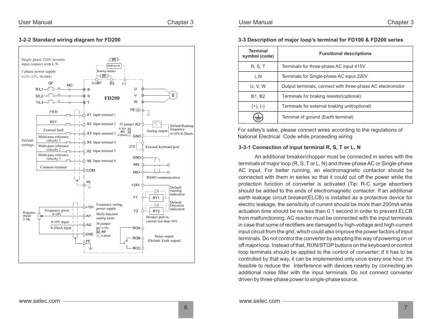
3-3 Description of major loop's terminal for FD100 & FD200 series
Terminalsymbol (code)
Functional descriptions
Terminals for three-phase AC input 415V
Terminals for Single-phase AC input 220V
Output terminals, connect with three-phase AC electromotor
Terminals for braking resistor(optional)
Terminals for external braking unit(optional)
Terminal of ground (Earth terminal)
R, S, T
L,N
U, V, W
B1, B2
(+), (-)
For safety's sake, please connect wires according to the regulations of
National Electrical Code while proceeding wiring
3-3-1 Connection of input terminal R, S, T or L, N
An additional breaker/chopper must be connected in series with the
terminals of major loop (R, S, T or L, N) and three-phase AC or Single-phase
AC input. For better running, an electromagnetic contactor should be
connected with them in series so that it could cut off the power while the
protection function of converter is activated (Tip: R-C surge absorbers
should be added to the ends of electromagnetic contactor. If an additional
earth leakage circuit breaker(ELCB) is installed as a protective device for
electric leakage, the sensitivity of current should be more than 200mA while
actuation time should be no less than 0.1 second in order to prevent ELCB
from malfunctioning. AC reactor must be connected with the input terminals
in case that some of rectifiers are damaged by high-voltage and high-current
input circuit from the grid, which could also improve the power factors of input
terminals. Do not control the converter by adopting the way of powering on or
off major loop. Instead of that, RUN/STOP buttons on the keyboard or control
loop terminals should be applied to the control of converter; if it has to be
controlled by that way, it can be implemented only once every one hour. It's
feasible to reduce the interference with devices nearby by connecting an
additional noise filter with the input terminals. Do not connect converter
driven by three-phase power to single-phase source.
3-2-2 Standard wiring diagram for FD200
MCR/L1
S/L2
T/L3
R
S
T
X1
X2
X3
X4
X5
X6
COM
+10V
AI1
AI2
GND
PE
W
V
U
PE
QF (+)/B1 B2 (-)
BR
0-10V / 0-20mA
RY1
ROA
ROB
ROC
RY2
0-10V
AI2
0-20mA
0-10V
AO
0-20mA
+24V
Y1
Y2
BR
J13
Braking resistor
Braking unit
3 phase power supply
Input terminal 1
Input terminal 2
Input terminal 3
Input terminal 4
Input terminal 5
Input terminal 6
FWD
REV
External fault
Multi-phase reference velocity 1
Multi-phase referencevelocity 2
Defau
lt setting
Jumper5Default setting:
operating frequencyAO
external Keyboard
interface
Multi-phase referencevelocity 3
Common terminal
Default setting:
Run command
Default setting:
Direction
Output of relay
Current is less than 30 ma
Frequency setting
Potentio-meter
Multi-functional AI
Input Input
Output of relay Jumper4
Default setting:
Fault output
Frequency given
PE
MVFD200
Single phase 220V inverterinput connect with L N
415V±15%50/60Hz MC
R/L1
S/L2
T/L3
R
S
T
X1
X2
X3
X4
X5
X6
COM
Input terminal 1
+10V
AI1
AI2
GND
PE
Frequency given 0-10V
0-20mA Input
0-10V Input J4 jumper
Frequency setting power supply
Multi-functionanalog inout
W
V
U
PE
QF (+)/B1 B2 (-)
Braking unit
BR
Analog output0-10V/0-20mA
RY1
ROA
ROB
ROC
Relay output
RY2
M
Breaker pull-in,current less than 30A
0-10V
AI2
0-20mA
J5 jumper0-10V
AO
0-20mA
+24V
Y1
Y2
BR
External keyboard portJ13
FWD
REV
External fault
Multi-pase referencevelocity 1
Default:Runningfrequency
Default:running
indication
Default:Directionindication
(Default: Fault output)
Potentio-meter
3-5K
Common terminal
AO
GND
485+
485-
GND
RS485 communication
Braking resistor
Input terminal 2
Input terminal 3
Input terminal 4
Input terminal 5
Input terminal 6
Multi-pase referencevelocity 2
Multi-pase referencevelocity 3
Default settings
3 phase power supply
Single phase 220V inverterinput connect with L N
415V±15%, 50/60Hz
PE

9www.selec.com
User ManualUser Manual
www.selec.com8
Chapter 3 Chapter 3
(a) correct (b) not recommend (c) error
3-3-4 Explanations of control loop terminals FD100
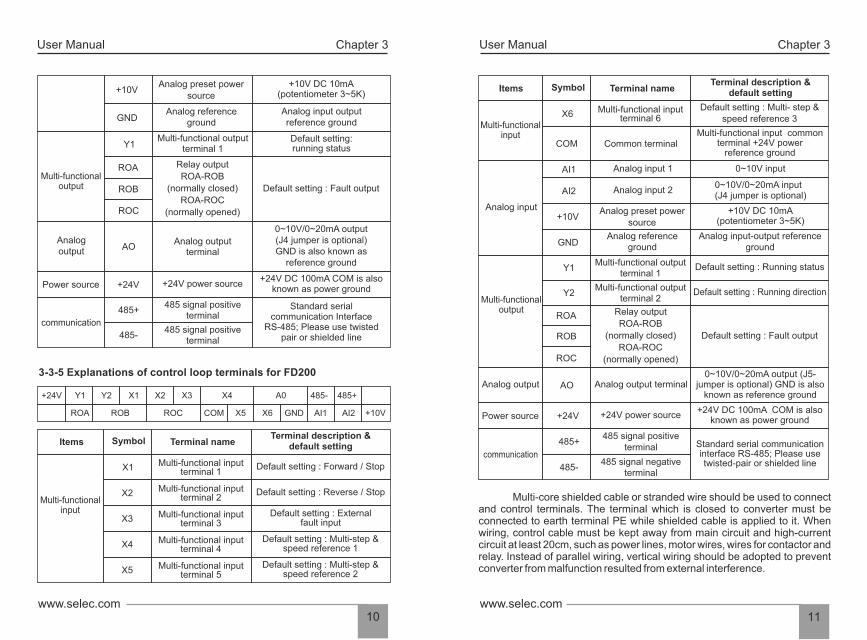
Terminal description &default setting Items Symbol Terminal name
Multi-functionalinput
X1
X2
X3
X4
X5
COM
AI1
AI2Analog input
Multi-functional inputterminal 1
Default setting : Forward / Stop
Multi-functional inputterminal 2
Default setting : Reverse / Stop
Multi-functional inputterminal 3
Default setting : External fault input
Multi-functional inputterminal 4
Default setting : Multi-step & speed reference 1
Multi-functional inputterminal 5
Default setting : Multi-step & speed reference 2
Common terminal Multi-functional input common
terminal +24V powerreference groung
Analog input 1 0~10V input
0~10V/0~20mA input (J3 jumper is optional)
Analog input 2
CN1
Needle base
COM
X5
RS485
485- 485+
8 76 54321
6 543
3-3-2 Connection of output terminal U, V, W
In any case, do not connect output terminals to phasing capacitor or
surge absorber. When the length of wire connecting converter with motor is
more than 50 meters, there may be a large amount of electric leakage caused
by the capacitors between the wiring, which may lead to over current;
additionally, to protect the insulation of motor from being damaged, an
additional output reactor must be installed.
Output terminals must be connected to three-phase motor in the
correct order; if motor rotates in the wrong direction, any two wires among U,
V and W electrical wiring can be switched with each other.
An additional noise filter can be installed to reduce the
electromagnetic interference of output if surroundings can be easily affected
by converter; interference can also be minimized by reducing its carrier
frequency.
3-3-3 Connection of braking resistors and braking unit
If inertia load is so large that converter needs to be shut off frequently
or in a short time, braking resistors or braking unit should be selected and
installed accordingly to solve the issue of insufficient braking capacity or
lengthen braking torque.
Do not connect positive(+) and negative(-) terminals of major loop to
braking resistor.
If there is no built-in braking unit, positive(+) and negative(-) terminals
of major loop should be connected to external braking units.
Terminals(B1, B2) of major loop must be connected with braking
resistors(Tip: terminal B1 or B2 indicates that this converter is the one with
built-in braking units)
3-3-4 Earth terminal PE
For safety's sake, earth terminal PE must be well grounded in order to
reduce noise. Please use the standard ground lead which should be as short
and thick as possible(its grounding impedance should be no more than
10Ω) Do not connect its ground lead with that of high-current loading
machine to ground at the same time, for example welder or high-power motor,
they must be grounded separately. All the converters must be connected to
the same earth terminal directly if two or more converters are installed
together; please refer to the wiring layout below:
11www.selec.com
User ManualUser Manual
www.selec.com10
Chapter 3 Chapter 3
Multi-functionalinput
X6 Multi-functional inputterminal 6
Common terminal
Terminal description &default setting Items Symbol Terminal name
COM
Default setting : Multi- step &speed reference 3
Multi-functional input commonterminal +24V power
reference ground
AI1
AI2
+10VAnalog input
GND
Analog input 1 0~10V input
0~10V/0~20mA input (J4 jumper is optional)
+10V DC 10mA(potentiometer 3~5K)
Analog preset power source
Analog input-output referenceground
Analog referenceground
Multi-functionaloutput
Y1
ROA
Default setting : Fault output
Relay output
ROA-ROB
(normally closed)
ROA-ROC
(normally opened)
ROB
ROC
Multi-functional output terminal 1
Default setting : Running status
Y2Multi-functional output
terminal 2Default setting : Running direction
0~10V/0~20mA output (J5-jumper is optional) GND is also
known as reference ground
Standard serial communicationinterface RS-485; Please usetwisted-pair or shielded line
Analog output
Power source
communication
AO
+24V
485+
485-
Analog output terminal
+24V power source
485 signal positiveterminal
485 signal negativeterminal
+24V DC 100mA COM is also known as power ground
Multi-core shielded cable or stranded wire should be used to connect and control terminals. The terminal which is closed to converter must be connected to earth terminal PE while shielded cable is applied to it. When wiring, control cable must be kept away from main circuit and high-current circuit at least 20cm, such as power lines, motor wires, wires for contactor and relay. Instead of parallel wiring, vertical wiring should be adopted to prevent converter from malfunction resulted from external interference.
Analog input 2
Multi-functionaloutput
Y1Default setting: running status
Multi-functional output terminal 1
ROA
Default setting : Fault output
Relay output
ROA-ROB
(normally closed)
ROA-ROC
(normally opened)
ROB
ROC
Analog output
0~10V/0~20mA output(J4 jumper is optional)GND is also known as
reference ground
Analog output terminal
AO
Power source+24V DC 100mA COM is also
known as power ground +24V power source+24V
communication
Standard serial communication Interface
RS-485; Please use twisted pair or shielded line
485 signal positive terminal
485+
485- 485 signal positive
terminal
3-3-5 Explanations of control loop terminals for FD200
Multi-functionalinput
X1
X2
X3
X4
Multi-functional inputterminal 1
Default setting : Forward / Stop
Multi-functional inputterminal 2
Default setting : Reverse / Stop
Multi-functional inputterminal 3
Default setting : External fault input
Multi-functional inputterminal 4
Default setting : Multi-step & speed reference 1
Terminal description &default setting Items Symbol Terminal name
X5 Multi-functional inputterminal 5
Default setting : Multi-step & speed reference 2
+24V Y1 Y2 X1 X2 X3 X4 A0 485- 485+
ROA ROB ROC COM X5 X6 GND AI1 AI2 +10V
+10V
GND
+10V DC 10mA(potentiometer 3~5K)
Analog preset power source
Analog input output reference ground
Analog referenceground
13www.selec.com
User ManualUser Manual
www.selec.com12
Chapter 4 Chapter 4
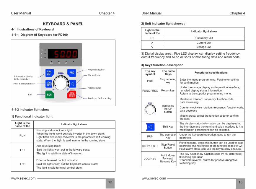
2) Unit Indicator light shows :
Light is thename of the
Indicator light show
Hz Frequency unit
A Current unit
V Voltage unit
3) Digital display area : Five LED display, can display setting frequency, output frequency and so on all sorts of monitoring data and alarm code.
3) Keys function description
KEYBOARD & PANEL
4-1 IIIustrations of Keyboard
4-1-1 Diagram of Keyboard for FD100
Indicator light show
RUN
Running status indicator light: When the lights went out said inverter in the down state;Light flash frequency converter in the parameter self learningstate; When the light is said inverter in the running state
F/R
And reversing lamp:
Said the lights went out in the forward state;
The light is said in a state of inversion.
L/R
External terminal control indicator:
Said the lights went out the keyboard control state;
The light is said terminal control state.
1) Functional indicator light:
Light is thename of the
4-1-2 Indicator light show
Information display& the return key
Point & the reverse key
Run
Stop key / Fault reset key
Potentiometer
The shift key
Programming keyThe name
Says
Return key
Increasingthe UPbutton
Shift Key
RUNThe operation
Key
Stop/ResetButton
Point Move/Forward/
Reverse Key
FUNC / ESC
15www.selec.com
User ManualUser Manual
www.selec.com14
Chapter 4 Chapter 5
5-1 Commissioning
5-1-1 Check before running
RUNNING
• Please check whether wiring is correct or not, especially output terminals(U, V, W) which mustn't be connected to power source; additionally, earth terminals PE must be well grounded as well.
• Please confirm that there is no short circuit or line-to-ground short circuit between terminals or any exposed charged component.
• Make sure that all the switches are off before it's connected to power source, and that converter will not malfunction or be started when it's switched on.
• Do not connect it to power s until its enclosure is assembled.
• Please confirm that all the components are fastened, such as terminals, pluggable connectors or screws.
5-1-2 Commissioning
Converter must be checked and confirmed comprehensively before
commissioning; its default running mode is to be controlled through
keyboard and panel.
• If converter functions properly, please preset its operating frequency first;
please press the button start commissioning and check whether its
output current/voltage is normal or not only after confirmation can it be
power-on.
• Please push the button & check the following points (its default jog
frequency is 5.0 HZ):
Whether motor is rotating in the right direction or not;
Whether its rotation is smooth or not (NO abnormal noise or vibration
is permitted)
Whether the acceleration or deceleration of motor is stable.
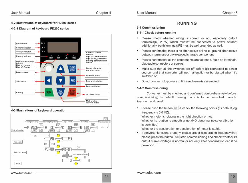
4-2 IIIustrations of keyboard for FD200 series
4-2-1 Diagram of keyboard FD200 series
Unit indicator
Current indication
Voltage indication
Positive and negative indicatorLight on: reverseLight off: forward
Potentiometer
Shift button
Running
Running indicator
Command sourceindicator Light on: terminal controlLight off: key pad controlBlinking: communication control
Display informationand return button
Increment button
Programming button
Decrement button
Stop/reset button
Multi-function selection button
4-3 Illustrations of keyboard operation
Basic information
Main Menu
Secondary Menu
Data
Setting frequency Operating frequency Output current Bar voltage Other information
FUNCESC
FUNCESC
FUNCESC
FUNCESC
FUNCESC
FUNCESC
FUNCESC
FUNCESC
PRG PRG PRG PRG
PRG
PRG
PRGdata storage and return
- - -
- +
- +
- +
- +
- +
- +
17www.selec.comwww.selec.com
16
User ManualUser Manual Chapter 5 Chapter 6
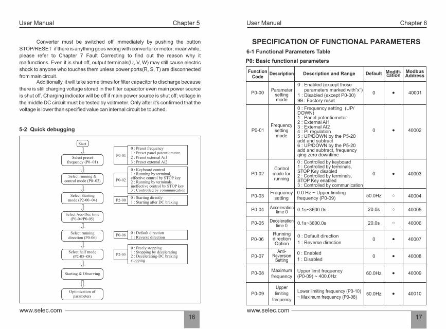
6-1 Functional Parameters Table
SPECIFICATION OF FUNCTIONAL PARAMETERS
P0: Basic functional parameters
Function Code
Description Description and Range Default Modifi-cation
Modbus Address
P0-00Parameter
settingmode
0 : Enabled (except those parameters marked with”x”) 1 : Disabled (except P0-00) 99 : Factory reset
0 40001
P0-01Frequency
settingmode
0 : Frequency setting (UP/DOWN)1 : Panel potentiometer 2 : External AI1 3 : External AI2 4 : PI regulation 5 : UP/DOWN by the P5-20add and subtract 6 : UP/DOWN by the P5-20add and subtract, frequencyqing zero downtime
0 40002
P0-02Control
mode forrunning
0 40003
P0-03Frequency
setting0.0 Hz ~ Upper limitingfrequency (P0-09)
50.0Hz 40004
P0-04 Acceleration time 0 0.1s~3600.0s 20.0s 40005
P0-05 Deceleration time 0
0.1s~3600.0s 20.0s 40006
P0-06Running direction Option
0 : Default direction
1 : Reverse direction 0 40007
P0-07Anti-
Reversion Setting
0 : Enabled
1 : Disabled 0 40008
P0-08Maximum frequency
Upper limit frequency(P0-09) ~ 400.0Hz
60.0Hz 40009
P0-09
Upper
limiting
frequency
Lower limiting frequency (P0-10)~ Maximum frequency (P0-08)
50.0Hz 40010
0 : Controlled by keyboard1 : Controlled by terminals,STOP Key disabled2 : Controlled by terminals,STOP Key enabled3 : Controlled by communication
Additionally, it will take some times for filter capacitor to discharge because
there is still charging voltage stored in the filter capacitor even main power source
is shut off. Charging indicator will be off if main power source is shut off; voltage in
the middle DC circuit must be tested by voltmeter. Only after it's confirmed that the
voltage is lower than specified value can internal circuit be touched.
Converter must be switched off immediately by pushing the button
STOP/RESET if there is anything goes wrong with converter or motor; meanwhile,
please refer to Chapter 7 Fault Correcting to find out the reason why it
malfunctions. Even it is shut off, output terminals(U, V, W) may still cause electric
shock to anyone who touches them unless power ports(R, S, T) are disconnected
from main circuit.
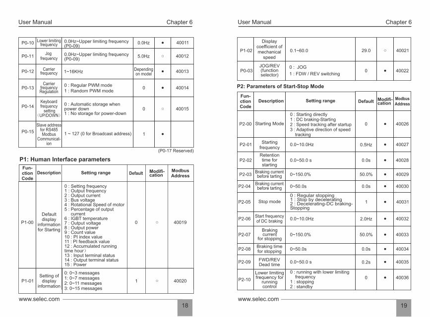
5-2 Quick debugging
Start
Select presetfrequency (P0~01)
Select running &control mode (P0~02)
Select Startingmode (P2-00~04)
Select Acc-Dec time(P0-04/P0-05)
Select runningdirection (P0-06)
Select half mode(P2-05~08)
Starting & Observing
Optimization of parameters
P0-01
0 : Preset frequency1 : Preset panel potentiometer2 : Preset external Ai13 : Preset external Ai2
0 : Keyboard control1 : Running by terminal,effective control by STOP key2 : Running by terminals,ineffective control by STOP key3 : Controlled by communication
0 : Starting directly1 : Starting after DC braking
P0-02
P2-00
P0-060 : Default direction1 : Reverse direction
P2-05
0 : Freely stopping1 : Stopping by decelerating2 : Decelerating-DC brakingstopping
User ManualUser Manual Chapter 6 Chapter 6
P2: Parameters of Start-Stop Mode
P1-02
Display coefficient of mechanical
speed
0.1~60.0 29.0
40021
P0-03 JOG/REV (function selector)
0 : JOG
1 : FDW / REV switching 0
40022
P2-00 Starting Mode
0 : Starting directly 1 : DC braking-Starting 2 : Speed tracking after startup 3 : Adaptive direction of speed tracking
0 40026
P2-01Starting
frequency 0.0~10.0Hz 0.5Hz 40027
Fun-ction Code
Description Setting range Default Modifi-cation
Modbus Address
P2-02 Retention time forstarting
0.0~50.0 s 0.0s 40028
P2-03Braking current before tarting 0~150.0% 50.0% 40029
P2-04Braking current before tarting 0~50.0s 0.0s 40030
P2-05 Stop mode
0 : Regular stopping 1 : Stop by decelerating 2 : Decelerating-DC braking-Stopping
1 40031
P2-06Start frequency of DC braking
0.0~10.0Hz 2.0Hz 40032
P2-07Brakingcurrent
for stopping 0~150.0% 50.0% 40033
P2-08Braking timefor stopping 0~50.0s 0.0s 40034
P2-09 FWD/REV Dead time
0.0~50.0 s 0.2s 40035
P2-10
Lower limiting frequency for
runningcontrol
0 : running with lower limiting frequency 1 : stopping 2 : standby
0 40036
19www.selec.comwww.selec.com
18
P1: Human Interface parameters
Setting range
0 : Setting frequency 1 : Output frequency 2 : Output current 3 : Bus voltage 4 : Rotational Speed of motor 5 : Percentage of output current 6 : IGBT temperature 7 : Output voltage 8 : Output power 9 : Count value 10 : PI index value 11 : PI feedback value 12 : Accumulated running time hour) 13 : Input terminal status 14 : Output terminal status 15 : Power
0 40019
0: 0~3 messages 1: 0~7 messages 2: 0~11 messages 3: 0~15 messages
1 40020
Default display
information for Starting
P1-00
Setting of display
information P1-01
Description DefaultModbusAddress
P0-10 Lower limiting frequency
0.0Hz~Upper limiting frequency (P0-09)
0.0Hz 40011
P0-11 Jog
frequency0.0Hz~Upper limiting frequency (P0-09)
5.0Hz 40012
P0-12 Carrier frequency 1~16KHz
Depending on model
40013
P0-13 Carrier
frequency Regulation
0 : Regular PWM mode 1 : Random PWM mode
0 40014
P0-14 Keyboard frequency
setting (UP/DOWN)
0 : Automatic storage when power down 1 : No storage for power-down
0 40015
P0-15
Slave address for RS485 Modbus
Communicat-ion
1 ~ 127 (0 for Broadcast address) 1
(P0-17 Reserved)
Modifi-cation
Fun-ction Code

User ManualUser Manual Chapter 6 Chapter 6
21www.selec.comwww.selec.com
20
P5: Input function parameters
P5-00AI1 lower
limiting value 0~10.00V 0.05V 40071
P5-01Corresponding setting for AI1
lower limit 0~100.0% 0.0% 40072
Function Code
Description Setting range Default Modifi-cation
Modbus Address
P5-02AI1 upper
limiting valueAI1 lower limiting value~10.00V 10.00V 40073
P5-03 Corresponding setting for AI1
upper limit 0~100.0% 100.0% 40074
P5-04AI1 input
filtering time 0.0s~10.0s 0.1s 40075
P5-05 AI2 lower
limiting value 0.00V~10.00V 0.05V 40076
P5-06Corresponding
setting forAI2 lower limit
0~100.0% 0.0% 40077
P5-07AI2 lower limiting value~10.00V
10.00V 40078
P5-08 40079
P5-09 0.0s~10.0s 0.1s 40080
P5-10Multi func-tional InputTerminal X1
0 : Disabled
1 : Forward
2 : Reverse
3 : Three-wire control
4 : Multi-phase reference
velocity 1
5 : Multi-phase reference
velocity 2
1 Forward 40081
P5-11 2Reverse 40082
P5-12 14 Fault 40083
AI2 inputfiltering time
0~100.0% 100.0%
Corresponding setting for
AI2 upper limit
Multi func-tional InputTerminal X2
Multi func-tional InputTerminal X3
AI2 upperlimiting value
P3: Parameters of Motor
P4: V/F Control Parameters
P3-00 Rated frequency F3 (P4-05) ~ 400.0Hz 50.0Hz 40039
P3-01 Rated voltage 200 ~ 440V Depending on model
40040
Function Code
Description Setting range Default Modifica-tion
Modbus Address
P3-02 Rated current 0.1 ~ 999.9ADepending on model 40041
P3-03 Rated power 0.1 ~ 630.0KW Depending on model 40042
P3-04Rated rotational
Speed 1 ~ 36000rpm 1440rpm 40043
P3-05 No-load current 0.1 ~ 999.9A Depending on model 40044
P3-06 Stator resistance 0.001 ~ 50.000Ω Depend on model 40045
P3-07 Excitation/Mag- netic inductance 0.1 ~ 5000.0mH Depend on
model 40046
(P3-08 ~ P3-12 Reserved)
P4-00V/F curve setting
0: General V/F1: 2 power V/F 2: 3 power V/F 3: high starting torque V/F 4: Self-setting V/F 5: Self-adaptive control
0 40052
P4-01 V/F Intermediate frequency 1 0.0Hz~ F2 (P4-03) 1.0Hz 40053
P4-02 V/F Intermediate voltage1 0 ~ rated voltage (P3-00) 5V 40054
P4-03 V/F Intermediate frequency 2 F1 (P4-01)~F3 (P4-05) 5.0Hz 40055
P4-04V/F Intermediate
voltage 2 0 ~ rated voltage(P3-00) 25V 40056
P4-05F2 (P4-03) ~ rated frequency (P3-00) 25.0Hz 40057
P4-06 0 ~ rated voltage (P3-00) 115V 40058
P4-07 Torque upgrade 0.0 ~ 15.0% 5.0 40059
P4-08 Slip compensation 0.0 ~ 10.0Hz 0.0 Hz 40060
P4-09 AVR function
0: Disabled 1: always enabled 2: only enabled inprocess of deceleration
40061
(P4-11~ P4-18 Reserved)
V/F IntermediateFrequency 3
V/F Intermediate voltage 3
P4-10Energy-efficientrunning
0: Disabled 1: Enabled
0 40062
0

User ManualUser Manual Chapter 6 Chapter 6
23www.selec.comwww.selec.com
22
P6-00 Y1 output options
0: Disabled, 1: Running 2: Direction, 3: Fault output 4: On standby 5: Frequency received 6: FDT 7: Upper limiting frequency received 8: Lower limiting frequency received 9: Setting count valuereceived 10: Designated count value received
1 40102
Func-tion
Code Description Setting range Default Modifi-
cationModbus Address
P6-01 2 40103
P6-02 Relay output
options 3 40104
P6-03 AO1 options 0 40105
0: Operating frequency 1: Output current 2: Bus voltage 3:Output voltage
P6-04 AO1 correction
coefficient100.0% 401060.0~250.0%
P6-05 Stop delaytime setting
0 401070~3000.0s
(P6-06~ P6-08 Reserved)
P6: Output function parameters
Y2 output options
P7: PI control parameters
P7-00 PI preset source options
0 40111
0 : Digital keyboard 1 : Panel potentiometer 2 : Analog channel AI1 3 : Analog channel AI2
Description Setting range Default Modifi-cation
Modbus Address
Func-tion
Code
PI feedback source options
0 : Analog channel AI1 1 : Analog channel AI2 0 40113
P7-01 0.00V 401120.00~10.00 VPI set value
P7-02
0: Positive
1: Negative 0 40114P7-03
PI output characteristics
options
P5-15 Reserved 40086
P5-13
Multi-func-
tional Input
Terminal X4 6: Multi- Phase reference
velocity 3
7: JOG forward
8: JOG reverse
9: Increasing frequency
10: Decreasing frequency
11: Acc-Dec time Option 1
12: Acc-Dec time Option 2
13: Stop of Acc/Dec
14: External fault Input
15: Fault reset
16: Regular stopping
17: External count value
input
18: count clear
19: program run
20: pause of program run
4 ref. velocity 1 40084
P5-145 ref.
velocity 2 40085
P5-16
P5-17
Reserved
Reserved
40087
40088
P5-18
P5-19
Terminal
control mode
Terminal
filtering time
0: Two-wire control mode 1 1: Two-wire control mode 2 2: Three-wire control mode 1 3: Three-wire control mode 2
2ms~100 ms
0
10 ms
40089
40090
P5-20
The range of
the UP/DOWN
increasing
decline
0.0~50.0Hz 0.1 40091
(P5-20~ P5-30 Reserved)
Multi-func-
tional Input
Terminal X5
(CN1needle
base input)
Multi-func-
tional Input
Terminal X6
Multi-func-
tional Input
Terminal X7
Multi-func-
tional Input
Terminal X8
User ManualUser Manual Chapter 6 Chapter 6
25www.selec.comwww.selec.com
24
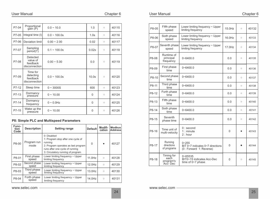
P8-05Fifth phase
speed Lower limiting frequency ~ Upper limiting frequency 15.0Hz 40132
P8-06 Sixth phase
speedLower limiting frequency ~ Upper limiting frequency 16.0Hz 40133
P8-07 40134
P8-08 0~6400.0 0.0 40135
P8-09First phase
time 0.0 40136
P8-10Second phase
time 40137
P8-11 Third phase time
40138
Runtime of principal
frequency
P8-12Forth phase
time 40139
Seventh phase speed
Lower limiting frequency ~ Upper limiting frequency 17.0Hz
P8-13
P8-14
P8-15
P8-16
P8-17
P8-18
Fifth phase time
Sixth phase time
Seventh phase time
Time unit of multi-velocity
Runningdirections
of programs
Timing foreach
program's Acc- Dec
0~255 BIT 0~7 indicates 0~7 directions (0 : Forward 1: Reverse)
0~65535 BIT0~15 indicates Acc-Dec time of 0~7 phase
0
0
0
40140
40141
40142
40143
40144
40145
0~6400.0
0~6400.0
0~6400.0
0~6400.0
0~6400.0
0~6400.0
0 : second 1 : minute 2 : hour
0.0
0.0
0.0
0.0
0.0
0.0
0~6400.0
Proportional gain (P) 0.0 ~ 10.0 1.0 40115
Integral time (I) 0.0 ~ 100.0s 1.0s 40116
Deviation limit 0.00 ~ 2.00 0.02 40117
P7-04
P7-05
P7-06
Sampling period(T) 0.1 ~ 100.0s 0.02s 40118P7-07
0.00 ~ 5.00 0.0 40119P7-08
Detectedvalue of
feedback disconnection
P7-09 0.0 ~ 100.0s 10.0s 40120
Time for detecting feedback
disconnection
P7-12 0 ~ 3000S 600 40123Sleep time
P7-13 0 ~ 10.00 0 40124Dormancy pressure
P7-14 0 ~ 0.0Hz 0 40125Dormancy frequency
P7-15 0 ~ 10.00 0 40126Wake up the
pressure
P8: Simple PLC and Multispeed Parameters
Description Setting range Default Modifi-cation
Modbus Address
P8-00Program run
mode
0: Disabled
1: Program stop after one cycle of
running
2: Program operates as last program
runs after one cycle of running
3: Circulatory running of program
0 40127
P8-01First phase
speed Lower limiting frequency ~ Upper limiting frequency
11.0Hz 40128
P8-02Second phase
speedLower limiting frequency ~ Upper limiting frequency
12.0Hz 40129
P8-03Third phase
speed Lower limiting frequency ~ Upper limiting frequency 13.0Hz 40130
P8-04 Forth phasespeed
Lower limiting frequency ~ Upper
limiting frequency 14.0Hz 40131
Func-tion
Code

User ManualUser Manual Chapter 6 Chapter 6
27www.selec.comwww.selec.com
26
Parameters of PA Enhancements
PA-00Acceleration
time 1 0.0~3600.0s 20.0s 40166
PA-01 Deceleration
time 1 0.0~3600.0s 20.0s 40167
Description Setting range DefaultModifi-cation
Modbus Address
PA-02 0.0~3600.0s 20.0s 40168
PA-03 Deceleration
time 2 0.0~3600.0s 20.0s 40169
PA-04Acceleration
time 30.0~3600.0s 20.0s 40170
PA-05 Deceleration
time 3 0.0~3600.0s 20.0s 40171
PA-06Jog
acceleration time
0.0~3600.0s 5.0s 40172
PA-07 0.0~3600.0s 5.0s 40173
PA-08 Hopping
frequency 10.0~Upper limiting frequency(P0-09) 40174
PA-09 40175
PA-10 40176
0.0Hz
PA-11 40177
PA-12 40178
PA-16 40182
Acceleration time 2
Jogacceleration
time
Func-tion
Code
Hoppingfrequency 2
Amplitude of Hopping
frequency
0.0~Upper limiting frequency(P0-09)
0.0~Upper limiting frequency(P0-09)
0.0~Upper limiting frequency(P0-09)
FDT levelvalue
FDT laggedvalue
0.0~FDT level value (PA-12)
Amplitude of Detected
frequency FAR
0.0~Upper limiting frequency(P0-09)PA-13
PA-14
PA-15
Setting count value
Specified count value
Under lockingfunction foroverload
1~65535
1~65535
0: Disabled 1: Enabled
0.0Hz
0.0Hz
0.0Hz
0.0Hz
0.0Hz
1
10
10
(PA-17~ PA-26 Reserved)
40179
40180
40181
P9: Protection Function parameters
P9-00Options foroverloadprotection
0 : Disabled 1 : Enabled 0 40148
P9-01Critical point of
overload protection
50~120% 110% 40149
Description Setting range Default Modifi-cation
Modbus Address
P9-02Overvoltage protection 0 : Disabled 1: Enabled 1 40150
P9-03Critical point of
Overvoltage 110.0~150.0% 118 40151
P9-04 Over-current
protection 0: Disabled 1: Enabled
1 40152
P9-05 Critical point of over-current
100~180% 180 40153
P9-06Phase-failure protection of
input
0 : Disabled 1 : Enabled
0 40154
P9-07Phase-failure protection of
output
0 : Disabled 1 : Enabled
0 40155
P9-08 Latest fault information
0~20 40156×
P9-09 Latest fault information
0~20 40157×
P9-10Latest two fault
messages 0~20 40158×
P9-11Operating frequency
of latest fault40159×
P9-12 Output current of latest fault
40160×
P9-13Bus voltage of
latest fault 40161×
P9-14 Input state of latest fault
40162×
Output state of latest fault
P9-16 Fault since the reset function
0 : invalid 1 : under-voltage fault alarm automatic reset (unlimited) 2 ~ 20 : fault self-recovery
0 40164
×P9-15
40163
(P9-17 Reserved)
Func-tion
Code
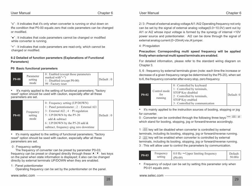
• It's mainly applied to the instruction sources of booting, stopping or jog
for converter.
0 : Converter can be controlled through the following three keys
which stand for booting, stopping, jog or forward/reverse accordingly.
1 : key will be disabled when converter is controlled by external
terminals, including its booting, stopping, jog or forward/reverse running.
2 : key will be enabled when converter is controlled by external
terminals, including its booting, stopping, jog or forward/reverse running.
3 : This will allow user to control the parameters by communication.
User ManualUser Manual Chapter 6 Chapter 6
29www.selec.comwww.selec.com
28
5, 6 : frequency by external terminals given (note: each time the increase or
decrease of a given frequency range be determined by the P5-20), when set
to 6, the frequency converter after every stop, zero frequency
4 : PI regulation
2 / 3 : Preset of external analog voltage AI1 /AI2 Operating frequency not only
can be set by the signal of external analog voltage(0.0~10.0V) sent out by
AI1 or AI2 whose input voltage is formed by the synergy of internal +10V
power source and potentiometer. AI2 can be done through the signal of
external analog current (0~20mA) via J4 jumper.
For detailed information, please refer to the standard wiring diagram on
Chapter 3.
Precaution: Corresponding multi speed frequency will be applied
firstly when external multi speed terminals are enabled.
• Frequency of output can be set by setting this parameter only when
P0-01 equals zero.
P0-02 Control mode
forrunning
0 : Controlled by keyboard1 : Controlled by terminals, STOP Key disabled2 : Controlled by terminals,STOP Key enabled3 : Controlled by communication
Default: 0
P0-03Frequency
setting0.0 Hz ~Upper limiting frequency
(P0-09)
Default:50.0Hz
“o” : It indicates that it's only when converter is running or shut down on
the condition that P0-00 equals zero that code parameters can be changed
or modified.
“” : It indicates that code parameters cannot be changed or modified while converter is running.
“×” : It indicates that code parameters are read-only, which cannot be changed or modified.
P0-00
• It's mainly applied to the setting of functional parameters; "factory reset" option should be used with caution, especially after all these parameters are set.
• It's mainly applied to the setting of functional parameters; "factory reset" option should be ssed with caution, especially after all these parameters are set.
1 : Panel potentiometer Operating frequency can be set by the potentiometer on the panel.
0 : Frequency setting The frequency of converter can be preset by parameter P0-03; frequency can be preset or changed directly through these two keys on the panel when state information is displayed; it also can be changed directly by external terminals UP/DOWN when they are enabled.
6-2 Detailed of function parameters (Explanations of Functional
Parameters)
P0 Basic functional parameters
Parameter settingmode
0 : Enabled (except those parametersmarked with"×")1 : Disabled (except P0-00)99 : Factory reset
Default : 0
P0-01 Frequency
settingmode
0 : Frequency setting (UP/DOWN)
1 : Panel potentiometer ; 2:External AI1
3 : External AI2 ; 4:PI regulation
5 : UP/DOWN by the P5-20
add & subtract
6 : UP/DOWN by the P5-20 add &
subtract, frequency qing zero downtime
Default : 0

User ManualUser Manual Chapter 6 Chapter 6
31www.selec.comwww.selec.com
30
• Running direction will be controlled by parameter "P0-06" when reverse direction is disabled. Both key and external terminals will be disabled.
• The setting of Acc-Dec time is based on maximum output frequency of running.
Upper limiting frequency
• These two parameters are also related to the amplitude of upper limiting
voltage and lower limiting voltage set by AI1 or AI2. For detailed information, please refer to P5-00~08.
• It's mainly applied to the setting of the amplitude between upper limiting
frequency and lower limiting frequency, which are also the range values of frequency regulation displayed on the panel potentiometer.
• It's mainly applied to the setting of running frequency for jog.
• The switching frequency of interior power module is controlled by this parameter.
Default: Dependingon model
P0-07 Anti-reversion Setting
0 : Enabled 1 : Disabled
Default: 0
P0-08MaximumFrequency
Upper limit frequency (P0-09) ~ 400.0Hz Default:60.0Hz
P0-09Lower limiting frequency (P0-10) ~Maximum frequency (P0-08)
Default:50.0Hz
Lower limiting frequency P0-10 0.0Hz ~ Upper limiting frequency (P0-09) Default:
0.0Hz
Jogfrequency P0-11 0.0Hz ~ Upper limiting frequency (P0-09) Default:
5.0Hz
Carrierfrequency
P0-12 1~16KHz
• Deceleration time 0 : Time for converter to decrease its frequency from maximum frequency (P0-08) to 0Hz.
• Acceleration time 0 : Time for converter to increase its frequency from 0Hz to maximum frequency (P0-08).
P0-04Acceleration
time 00.1s~3600.0s
P0-05Deceleration
time 00.1s~3600.0s
Default:20.0s
Default:20.0s
Please refer to following graph.:
P0-06Running
direction option0:Default direction1:Reverse direction
Default: 0
• Running direction can be preset through this parameter, which will also
be taken as forward direction by default. It will also be chosen as a
reference for reverse direction which is controlled by key as well
as external terminals
0 : Converter will be running in default direction
1 : Running direction will be changed, which also means that it is
changed by altering any two of motor wires(U, V, W).
Maximum frequency
Output frequency
Preset frequency
Actual deceleration time
Preset deceleration timePreset acceleration time
Actual acceleration time
Time

User ManualUser Manual Chapter 6 Chapter 6
33www.selec.comwww.selec.com
32
P1: Human Interface parameters
Defaultdisplay
informationfor Starting
P1-00
0:Setting frequency1:Output frequency 2:Output current3:Bus voltage 4:Rotational Speed of motor5:Percentage of output current 6:IGBT temperature7:Output voltage 8:Output power 9:Count value 10:PI index value 11:PI feedback value12:Accumulated running time (hour)13:Input terminal status 14:Output terminal status15:Power
Default: 0
Ÿ It's mainly applied to the setting of default display information for starting.
1
0
2
3
4
5
6
7
SetValue
Discriptions
Preset Frequency
Output Frequency
Bus Voltage
Output Current
Rotational speed of motor
Percentage of output current
IGBT Temperature
Output Voltage
Unit
Hz
V
A
r / min
0C
V
Hz
Status Information
• It's mainly used to alter the operating frequency through keys or external terminals UP/DOWN. Whether a modified operating frequency would be saved in the parameter P0-03 after it powers down depends on the setting of this parameter.
Audio noise and heat effect generated during the process of running
are mainly affected carrier frequency. Carrier frequency must be increased
slightly in order to achieve a quieter running; however, the maximum load will
be decreased somehow at the same time, which may increase the risk of
electric leakage between motor lines or between wires and earth. When
ambient temperature is too high or there is too much load for motor, carrier
frequency should be decreased properly to improve converter's thermal
characteristics. Generally, carrier frequency will be preset right before delivery;
therefore, it doesn't need to be reset or modified. It should be used by
derating if the carrier frequency which is being applied by operator exceeds
the default value preset by factory.
CarrierfrequencyRegulation
P0-130:Regular PWM mode
1:Random PWM modeDefault: 0
• Noise frequency of motor is fixed while running in regular PWM mode;
frequency domain of noise is wider while the running of motor is set in random
PWM mode.
Keyboardfrequency
(UP/DOWN)P0-14
0:Automatic storage when it powers down1:No storage when it powers down
Default: 0
User ManualUser Manual Chapter 6 Chapter 6
35www.selec.comwww.selec.com
34
It's mainly applied to the features setup of key; and when running
is under the control of keyboard:
1: Forward direction and reverse direction can be switched to each other
by key.
0: Jogging will be enabled by pressing key;
P2 : Parameters of Start-Stop Mode
Starting Mode
0: It starts directly with the original start frequency;
2: The speed tracking after startup. Frequency converter for motor speed, but themotor according to the last stop in the direction of the direction to run by default.(11 kw models more effective)
3: adaptive direction of speed tracking. Before starting the inverter in the automaticdetection the direction of the electric motor no impact on the smooth startup ofrotation of the motor. (11 kw models more effective)
1: DC braking-Starting -- DC braking will be enabled first; then motor starts runningwith the original start frequency; this is applicable for the situation when reverse maybe caused by small inertia load during the process of starting.
P2-00
0: Starting directly 1: DC braking-Starting2:Speed tracking after startup3:Adaptive direction of speed tracking
Default: 0
• It's only when P2-00 equals 1 that DC braking can be enabled before starting. When converter is about to be started, DC braking should be proceeded according to thepreset braking current(P2-03); after the preset braking time(P2-04) is over, it will start running.
• Braking current means the percentage comparing with rated current. The higher braking DC is, the stronger braking force will be.
Default:0.5 Hz
Default:0.0s
• Applicable starting frequency can ensure that there is enough torque for starting. Retention time for starting is needed for the formation of magnetic flow while motor is on standby, so that it can start accelerating after start frequency is stabilized for a certain time.
P2-01Starting
frequency 0.0~10.0Hz
P2-02 Retention time
for starting 0.0~50.0 s
Default: 50%
Default: 0.0s
P2-03 0~150.0%
P2-04 0~50.0 s
Braking current before starting
Braking time before starting
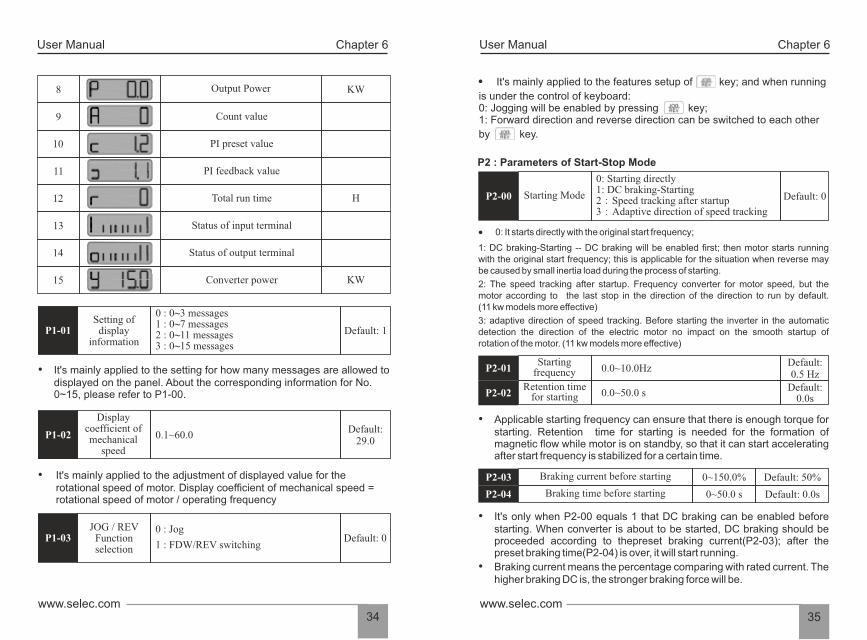
• It's mainly applied to the setting for how many messages are allowed to displayed on the panel. About the corresponding information for No. 0~15, please refer to P1-00.
0.1~60.0
• It's mainly applied to the adjustment of displayed value for the rotational speed of motor. Display coefficient of mechanical speed = rotational speed of motor / operating frequency
Setting ofdisplay
informationP1-01
0 : 0~3 messages 1 : 0~7 messages2 : 0~11 messages3 : 0~15 messages
Default: 1
Displaycoefficient ofmechanical
speed
P1-02Default:
29.0
0 : Jog
1 : FDW/REV switching
JOG / REVFunctionselection
P1-03 Default: 0
8 Output Power KW
10
9
11
12
13
14
15
Count value
PI preset value
Total run time
PI feedback value
Status of input terminal
Status of output terminal
Converter power
H
KW
User ManualUser Manual Chapter 6 Chapter 6
37www.selec.comwww.selec.com
36
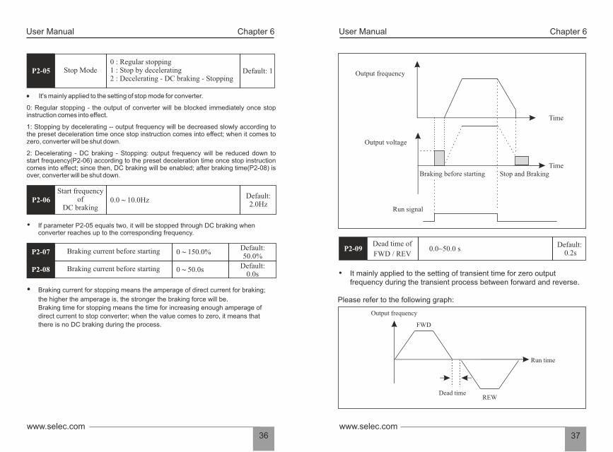
Dead time of
FWD / REV 0.0~50.0 s
• It mainly applied to the setting of transient time for zero output frequency during the transient process between forward and reverse.
Please refer to the following graph:
P2-09Default:
0.2s
Output frequency
Output voltage
Braking before starting Stop and Braking
Time
Run signal
Time
Output frequency
FWD
Dead timeREW
Run time
P2-05 Default: 1Stop Mode 0 : Regular stopping 1 : Stop by decelerating 2 : Decelerating - DC braking - Stopping
0: Regular stopping - the output of converter will be blocked immediately once stopinstruction comes into effect.
2: Decelerating - DC braking - Stopping: output frequency will be reduced down tostart frequency(P2-06) according to the preset deceleration time once stop instructioncomes into effect; since then, DC braking will be enabled; after braking time(P2-08) isover, converter will be shut down.
It's mainly applied to the setting of stop mode for converter.
1: Stopping by decelerating -- output frequency will be decreased slowly according tothe preset deceleration time once stop instruction comes into effect; when it comes tozero, converter will be shut down.
P2-06Default:2.0Hz
0.0 ~ 10.0HzStart frequency
of DC braking
• If parameter P2-05 equals two, it will be stopped through DC braking when converter reaches up to the corresponding frequency.
P2-07Default:50.0%
0 ~ 150.0%Braking current before starting
P2-08 Braking current before starting 0 ~ 50.0s Default:0.0s
• Braking current for stopping means the amperage of direct current for braking;
the higher the amperage is, the stronger the braking force will be.
Braking time for stopping means the time for increasing enough amperage of
direct current to stop converter; when the value comes to zero, it means that
there is no DC braking during the process.
User ManualUser Manual Chapter 6 Chapter 6
21www.selec.comwww.selec.com
20
User ManualUser Manual Chapter 6 Chapter 6
39www.selec.comwww.selec.com
38
P4: V/F Control Parameters
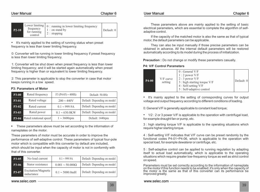
• It's mainly applied to the setting of corresponding curves for output voltage and output frequency according to different conditions of loading.
0: General V/F is generally applicable to constant load torque;
3 : high starting torque V/F is applicable to the operating situations which require higher starting torque.
• 1/2 : 2 or 3 power V/F is applicable to the operation with centrifugal load, for example draught fan or pump, etc.
4 : Self-setting V/F indicates that V/F curve can be preset randomly by the functional codes P4-01~P4-06, which is applicable to the operation with special load, for example dewaterer or centrifuge, etc.
5 : Self-adaptive control can be applied to running regulation by adapting itself to actual load automatically, which is applicable to the operating situations which require greater low-frequency torque as well as strict control on speed.
Parameters must be set correctly according to the information of nameplate on the motor if this function needs to be enabled; it's only when the capacity of the motor is the same as that of this converter can its performance be improved greatly.
They can also be input manually if those precise parameters can be obtained in advance. All the internal default parameters will be restored automatically according to its model during the process of initialization.
If the capacity of the matched motor is also the same as that of typical motor, the default parameters can be applicable.
These parameters above are mainly applied to the setting of basic electrical parameters, which are essential to complete the algorithm of self-adaptive control.
Precaution : Do not change or modify these parameters casually.
P4-00 Default: 0V/F curve
setting
0 : General V/F 1 : 2 power V/F 2 : 3 power V/F3 : high starting torque V/F4 : Self-setting V/F 5 : Self-adaptive control
P2-10 Default: 0
Lower limitingfrequency
for running control
0:running in lower limiting frequency 1:on stand by2:stopping
1: Converter will be shut down when preset frequency is less than lower limiting frequency; and it will be started again automatically when preset frequency is higher than or equivalent to lower limiting frequency.
0: Converter will be running in lower limiting frequency if preset frequency is less than lower limiting frequency.
2: This parameter is applicable to stop the converter in case that motor keeps running in a low speed.
• It's mainly applied to the setting of running status when preset frequency is less than lower limiting frequency.
P3-00
P3: Parameters of Motor
Rated frequency
Rated voltage
Rated current
Rated power
Rated rotational speed
P3-01
P3-02
P3-03
P3-04
F3 (P4-05) ~ 400Hz
200 ~ 440V
0.1 ~ 999.9A
0.1 ~ 630.0KW
1 ~ 3600rpm
Default: 50.0Hz
Default: Depending on model
Default: Depending on model
Default: 1440rpm
Default: Depending on model
P3-05 No-load current
Stator resistance
Excitation/Magneticinductance
P3-06
P3-07
0.1 ~ 999.9A
0.001 ~ 50.000Ω
0.1 ~ 5000.0mH Default: Depending on model
Default: Depending on model
Default: Depending on model
These parameters above must be set according to the information of
nameplates on the motor.
These parameters of motor must be accurate in order to improve the
performance of self-adaptive control. These parameters of typical four-pole
motor which is compatible with this converter by default are included,
which should be input when the capacity of motor is not in conformity with
that of this converter.
User ManualUser Manual Chapter 6 Chapter 6
41www.selec.comwww.selec.com
40
0.0~15.0%P4-07Default:
5.0Torque upgrade
This parameter can make compensation for output voltage when converter is running in a low frequency, so that the characteristics of low-frequency torque which is controlled by V/F can be compensated and upgraded.
If the setting of torque upgrade is too high, not only motor tends to be overheated but also over current may be caused by it. In general, the setting of torque upgrade must be no more than 10%. To prevent converter from over current effectively, this parameter must be adjusted properly. This parameter should be increased whenever there is heavy load; otherwise, please decrease this parameter.
• The practical slip of motor varies from load to load. Output frequency can be adjusted automatically according to the condition of loading by this functional parameter, so that compensation can be made for the influence of load on rotational speed of motor.
0.0~10.0HzP4-08Default: 0.0Hz
Slipcompensation
• AVR function is also known as Automatic Voltage Regulation function. Adjustment will be made automatically to stabilize output voltage whenever there is fluctuation of input voltage, so that it can prevent converter from overheat of motor caused by high output voltage or poor performance caused by low output voltage.
P4-09 Default: 0AVR
function
0 : Disabled 1 : always enabled 2 : only enabled in process of deceleration
0:Disabled1:Enabled
P4-10 Default: 0Energy-efficient
running
• During the process of no-load or light-load running, output voltage can be adjusted properly to achieve automatic energy conservation by detecting load current. This parameter is applicable to the load of draught fanor pump.
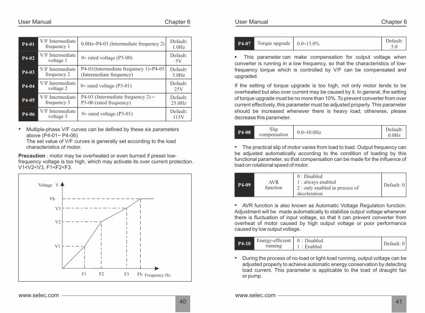
• Multiple-phase V/F curves can be defined by these six parameters above (P4-01~ P4-06) The set value of V/F curves is generally set according to the load characteristics of motor.
0.0Hz~P4-03 (Intermediate frequency 2)
0~ rated voltage (P3-00)
P4-01(Intermediate frequency 1)~P4-05 (Intermediate frequency)
0~ rated voltage (P3-01)
P4-03 (Intermediate frequency 2) ~P3-00 (rated frequency)
0~ rated voltage (P3-01)
P4-01Default: 1.0Hz
V/F Intermediatefrequency 1
P4-02
P4-03
P4-04
P4-05
P4-06
V/F Intermediatevoltage 1
V/F Intermediatefrequency 2
V/F Intermediatevoltage 2
V/F Intermediatefrequency 3
V/F Intermediatevoltage 3
Default: 5V
Default: 5.0Hz
Default: 25V
Default: 25.0Hz
Default: 115V
Precaution : motor may be overheated or even burned if preset low-frequency voltage is too high, which may activate its over current protection.V1<V2<V3, F1<F2<F3.
Voltage V
Vb
V3
V2
V1
F1 F2 F3 Fb Frequency Hz
User ManualUser Manual Chapter 6 Chapter 6
43www.selec.comwww.selec.com
42
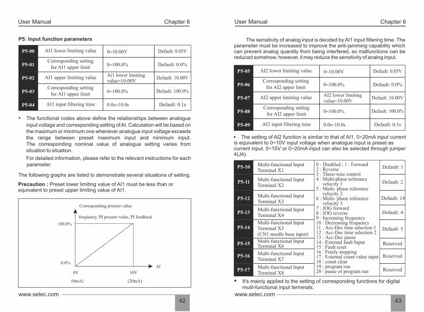
The sensitivity of analog input is decided by AI1 input filtering time. The parameter must be increased to improve the anti-jamming capability which can prevent analog quantity from being interfered, so malfunctions can be reduced somehow; however, it may reduce the sensitivity of analog input.
P5-10
P5-11
P5-12
P5-13
P5-14
P5-15
P5-16
P5-17
Multi-functional InputTerminal X1
Multi-functional Input Terminal X2
Multi-functional InputTerminal X3
Multi-functional InputTerminal X4
Multi-functional InputTerminal X5(CN1 needle base input)
Multi-functional InputTerminal X6
Multi-functional InputTerminal X7
Multi-functional InputTerminal X8
0 : Disabled ; 1 : Forward 2 : Reverse3 : Three-wire control 4 : Multi-phase reference velocity 1 5 : Multi- phase reference velocity 2 6 : Multi- phase reference velocity 3 7 : JOG forward8 : JOG reverse 9 : Increasing frequency 10 : Decreasing frequency 11 : Acc-Dec time selection 1 12 : Acc-Dec time selection 2 13 : Acc-Dec pause 14 : External fault Input 15 : Fault reset 16 : Freely stopping 17 : External count value input 18 : count clear 19 : program run 20 : pause of program run
Default: 1
Default: 2
Default: 14
Default: 4
Default: 5
Reserved
Reserved
Reserved
Ÿ It's mainly applied to the setting of corresponding functions for digitalmutil-functional input terminals.
The setting of AI2 function is similar to that of AI1. 0~20mA input current is equivalent to 0~10V input voltage when analogue input is preset as current input. 0~10V or 0~20mA input can also be selected through jumper 4(J4).
0~10.00VP5-05 Default: 0.05VAI2 lower limiting value
AI2 upper limiting value
AI2 input filtering time
0~100.0%
AI2 lower limiting value~10.00V
0~100.0%
0.0s~10.0s
Default: 0.0%
Default: 10.00V
Default: 100.0%
Default: 0.1s
P5-06
P5-07
P5-08
P5-09
Corresponding settingfor AI2 upper limit
Corresponding settingfor AI2 upper limit
• The functional codes above define the relationships between analogue
input voltage and corresponding setting of AI. Calculation will be based on the maximum or minimum one whenever analogue input voltage exceeds the range between preset maximum input and minimum input. The corresponding nominal value of analogue setting varies from situation to situation.
For detailed information, please refer to the relevant instructions for each parameter.
The following graphs are listed to demonstrate several situations of setting.
Precaution : Preset lower limiting value of AI1 must be less than orequivalent to preset upper limiting value of AI1.
0~10.00VP5-00 Default: 0.05VAI1 lower limiting value
P5: Input function parameters
AI1 upper limiting value
Corresponding settingfor AI1 upper limit
AI1 input filtering time
0~100.0%
Ai1 lower limiting value~10.00V
0~100.0%
0.0s~10.0s
Default: 0.0%
Default: 10.00V
Default: 100.0%
Default: 0.1s
P5-01
P5-02
P5-03
P5-04
Corresponding settingfor AI1 upper limit
Corresponding present value
frequency, PI present value, PI feedback
100.0%
0.0%
0V 10V
(0mA) (20mA)
AI
User ManualUser Manual Chapter 6 Chapter 6
45www.selec.comwww.selec.com
44
10
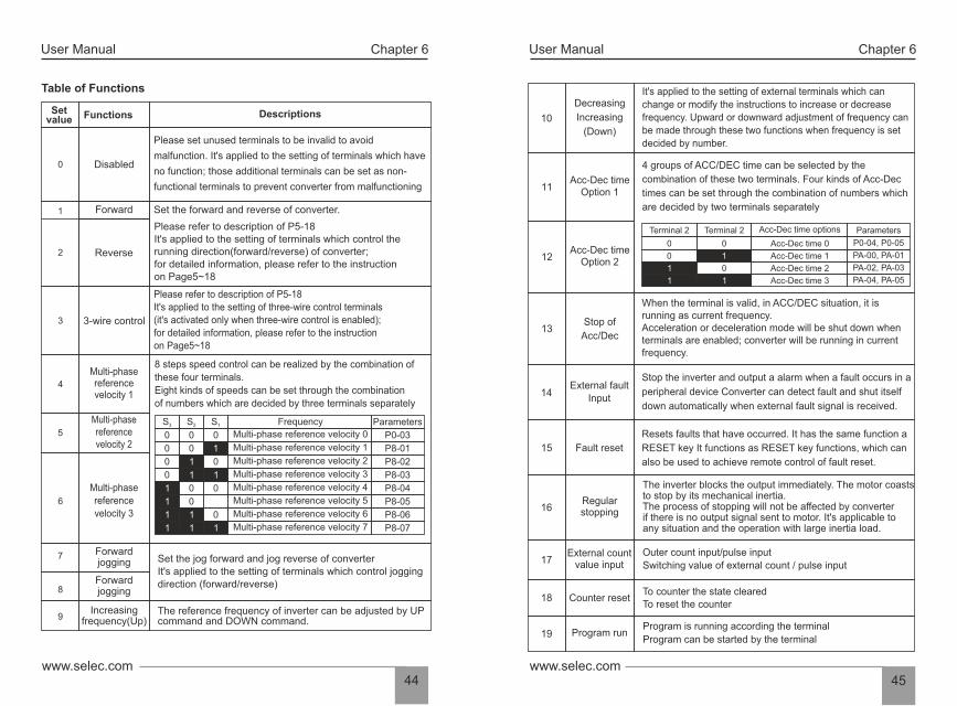
Decreasing
Increasing
(Down)
It's applied to the setting of external terminals which can
change or modify the instructions to increase or decrease
frequency. Upward or downward adjustment of frequency can
be made through these two functions when frequency is set
decided by number.
11 Acc-Dec time
Option 1
4 groups of ACC/DEC time can be selected by the
combination of these two terminals. Four kinds of Acc-Dec
times can be set through the combination of numbers which
are decided by two terminals separately
12 Acc-Dec time
Option 2
13 Stop of
Acc/Dec
When the terminal is valid, in ACC/DEC situation, it isrunning as current frequency. Acceleration or deceleration mode will be shut down whenterminals are enabled; converter will be running in currentfrequency.
14 External fault
Input
Stop the inverter and output a alarm when a fault occurs in a
peripheral device Converter can detect fault and shut itself
down automatically when external fault signal is received.
15 Fault reset
Resets faults that have occurred. It has the same function a
RESET key It functions as RESET key functions, which can
also be used to achieve remote control of fault reset.
16 Regular stopping
The inverter blocks the output immediately. The motor coaststo stop by its mechanical inertia. The process of stopping will not be affected by converterif there is no output signal sent to motor. It's applicable toany situation and the operation with large inertia load.
17 External count
value input Outer count input/pulse input
Switching value of external count / pulse input
Counter resetTo counter the state cleared To reset the counter
18
19 Program runProgram is running according the terminal
Program can be started by the terminal
Terminal 2 Terminal 2 ParametersAcc-Dec time options
0 0
0
1
1
1 1
0
Acc-Dec time 0
Acc-Dec time 1
Acc-Dec time 2
Acc-Dec time 3
P0-04, P0-05
PA-00, PA-01
PA-02, PA-03
PA-04, PA-05
Table of Functions
Set value Functions Descriptions
0
1
2
3
Disabled
Forward
Reverse
3-wire control
Please set unused terminals to be invalid to avoid
malfunction. It's applied to the setting of terminals which have
no function; those additional terminals can be set as non-
functional terminals to prevent converter from malfunctioning
Set the forward and reverse of converter.
Please refer to description of P5-18 It's applied to the setting of terminals which control therunning direction(forward/reverse) of converter;for detailed information, please refer to the instructionon Page5~18
Please refer to description of P5-18 It's applied to the setting of three-wire control terminals(it's activated only when three-wire control is enabled);for detailed information, please refer to the instructionon Page5~18
8 steps speed control can be realized by the combination of
these four terminals.
Eight kinds of speeds can be set through the combination
of numbers which are decided by three terminals separately
Multi-phase referencevelocity 1
4
5
Multi-phase referencevelocity 2
6
Multi-phase
reference
velocity 3
7
8
9
Forwardjogging
Increasing frequency(Up)
Set the jog forward and jog reverse of converter It's applied to the setting of terminals which control jogging direction (forward/reverse)
The reference frequency of inverter can be adjusted by UP command and DOWN command.
Forwardjogging
S3 S2 S1
0 0 0
0 0 1
0 0
0
0 0
0
0
1
1 1
1
1
1
1 1
1
1
1
Frequency
Multi-phase reference velocity 0
Multi-phase reference velocity 1
Multi-phase reference velocity 2
Multi-phase reference velocity 3
Multi-phase reference velocity 4
Multi-phase reference velocity 5
Multi-phase reference velocity 6
Multi-phase reference velocity 7
Parameters
P0-03
P8-01
P8-02
P8-03
P8-04
P8-05
P8-06
P8-07

User ManualUser Manual Chapter 6 Chapter 6
47www.selec.comwww.selec.com
46
3-wire control mode 1
3: Rising edge of pulse and terminal SIn will be enabled while three-wire control mode 2 is enabled; run command is controlled by both REV of FWD keys which control the running direction at the same time; stop signal is generated by a on instant input terminal SIn. The function of corresponding input terminal is defined by SIn terminal as No.3 function "three-wire control".
3-wire control mode 2
Tips: As for two-wire control mode, with the premise of the following two points, even control terminals FWD/REV remain enabled, converter will not be running any more after stop signal disappears:
1.FWD/REV terminals are enabled; 2.Converter is shut down because of stop signal generated by the other source; FWD/REV terminals must be enabled again if converter needs to be started.
FWD
REV
COM
SB1
SB2
K
SinK
OFF
ON
Run
SB2
SB1
Stop
Forward
Reverse
FWD
REV
COM
SB1
SB2
SB3
SInStop
SB3
SB2
Reverse running
Forward runningSB1
Keep the converter in current running frequency when thEterminal is valid, and the running time is not include inprogram running time It can keep converter running incurrent frequency when terminals are enabled; during thisperiod, running time is not count into the time of program run
20
Pause of
program
Run
20 -31 Reserved Reserved
0: Two-wire control mode 1 is the most common two-wire mode, which can make directions conformed with each other; Forward or reverse direction will be decided by the instructions from FWD/REV terminals.
• This parameter defines three different control modes of external terminals.
P5-18 Default: 0Terminal control
mode
0 : Two-wire control mode 11 : Two-wire control mode 22 : Three-wire control mode 13 : Three-wire control mode 2
2-wire control mode 1
1: Two-wire control mode 2 can keep directions separated with each other; FWD terminal will be enabled while this mode is enabled; but direction will be decided by REV.
2-wire control mode 2
2: Rising edge of pulse and terminal SIn will be enabled while three-wire control mode 1 is enabled; direction is controlled by REV key; stop signal is controlled by input terminal SIn. The function of corresponding input terminal is defined by SIn terminal as No.3 function "three-wire control".
FWD
REV
COM
K1
K2
K1 K2
OFF OFF
OFF
OFF
ON
ON
Commandcode
Stop
Forward
Reverse
FWD
REV
COM
K1
K2
K1 K2
OFF OFF
OFFON
ON
CommandcodeStop
Forward
ReverseON
ONOFF Stop

User ManualUser Manual Chapter 6 Chapter 6
49www.selec.comwww.selec.com
48
Table of Output Functions
Setvalue
Functions Descriptions
0 Disabled Output terminals without any function
1 Running When the converter is running, output the close signal It means that converter is running; closed signal is output.
2 DirectionOn run reverse, output the close signal It indicates the running direction of converter; closed signal is output when it's running in reverse direction.
3 Fault outputWhen the converter is out of work, output the close signalClosed signal is output when it's malfunctioning.
4 On standby
Establish main circuit and control circuit power, theprotection function of the converter is not change, and theconverter is running, output the close signal Major loopand control circuit are established; protection function isn'tenabled; converter is on standby; closed signal is output.
5 Frequency received
Please refer to the explanations of function code PA-11~13
6 FDT
ON: Running frequency reaches the value of P0-09 Signal "ON" is output when running frequency reaches upper limiting frequency
7Upper limiting
frequency received
ON: Running frequency reaches the value of P0-10
Signal "ON" is output when running frequency is
equivalent to or lower than lower limiting frequency
8
Lower frequency
limitingreceived
ON: the value of count reach the setting value of PA-14
Signal "ON" is output when count value reaches the value
set by PA-14.9
Setting count value
received
Designatedcount value
received
ON: the value of count reach the setting value of PA-15Signal "ON" is output when count value reaches the valueset by PA-15.
10
11~15 Reserved Reserved
• It's mainly used to set the sensitivity of terminals from X1 to X8. The parameter must be increased to improve the anti-jamming capability which can prevent DI terminals from being interfered, so that malfunctions can be reduced somehow; however, it may reduce the sensitivity of DI terminals.
Ÿ When frequency increment/decrement with external terminal set, every
time the frequency of the increase or decrease in value is decided by the
P5-20.
0: Disabled1: Running2: Direction3: Fault output4: On standby5: Frequency received6: FDT7: Upper limiting frequency received8: Lower limiting frequency received9: Setting count value received10: Designated count value received
Default: 1
Default: 2
Default: 3
P6: Output function parameters
Y1 output options
Y2 output options
Relay output
options
P5-19Default:
10msTerminal filtering
mode2ms ~ 100ms
P5-20 0.1The range of the
UP/DOWNincreasing decline
0.0~50.0Hz
P6-00
P6-01
P6-02
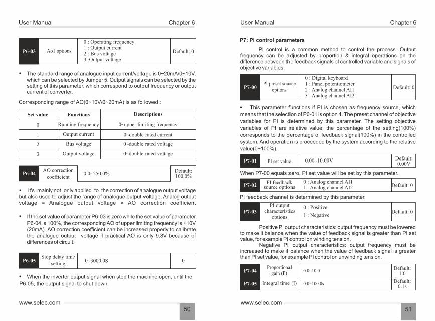
User ManualUser Manual Chapter 6 Chapter 6
51www.selec.comwww.selec.com
50
This parameter functions if PI is chosen as frequency source, which
means that the selection of P0-01 is option 4. The preset channel of objective
variables for PI is determined by this parameter. The setting objective
variables of PI are relative value; the percentage of the setting(100%)
corresponds to the percentage of feedback signal(100%) in the controlled
system. And operation is proceeded by the system according to the relative
value(0~100%).
When P7-00 equals zero, PI set value will be set by this parameter.
0 : Analog channel AI1 1 : Analog channel AI2
PI feedback channel is determined by this parameter.
PI outputcharacteristics
options
0 : Positive
1 : Negative
Positive PI output characteristics: output frequency must be lowered to make it balance when the value of feedback signal is greater than PI set value, for example PI control on winding tension. Negative PI output characteristics: output frequency must be increased to make it balance when the value of feedback signal is greater than PI set value, for example PI control on unwinding tension.
Integral time (I)
P7: PI control parameters
PI control is a common method to control the process. Output frequency can be adjusted by proportion & integral operations on the difference between the feedback signals of controlled variable and signals of objective variables.
0 : Digital keyboard1 : Panel potentiometer2 : Analog channel AI1 3 : Analog channel AI2
Default: 0 P7-00PI preset source
options
0.00~10.00V Default: 0.00VP7-01 PI set value
Default: 0P7-02PI feedback
source options
Default: 0P7-03
Default: 1.0P7-04
Proportionalgain (P)
0.0~10.0
P7-05 0.0~100.0s Default:
0.1s
0 : Operating frequency 1 : Output current 2 : Bus voltage 3 :Output voltage
Default: 0
• The standard range of analogue input current/voltage is 0~20mA/0~10V, which can be selected by Jumper 5. Output signals can be selected by the setting of this parameter, which correspond to output frequency or output current of converter.
Corresponding range of AO(0~10V/0~20mA) is as followed :
Descriptions
0~upper limiting frequency
0~double rated current
0~double rated voltage
0~double rated voltage
Set value Functions
0
1 Output current
2 Bus voltage
3 Output voltage
• When the inverter output signal when stop the machine open, until the
P6-05, the output signal to shut down.
P6-03 Ao1 options
Running frequency
Default:100.0%
P6-04 0.0~250.0% AO correction
coefficient
0P6-05 0~3000.0SStop delay time
setting
• If the set value of parameter P6-03 is zero while the set value of parameter P6-04 is 100%, the corresponding AO of upper limiting frequency is +10V (20mA). AO correction coefficient can be increased properly to calibrate the analogue output voltage if practical AO is only 9.8V because of differences of circuit.
It's mainly not only applied to the correction of analogue output voltage but also used to adjust the range of analogue output voltage. Analog output voltage = Analogue output voltage × AO correction coefficient

Deviation limitof PI control
Deviation limit of PI control defines the comparison between PI system output and maximum deviation value which is limited by closed-loop set value. As is shown in the graph, PI regulator is shut down while it's within deviation limit. The precision and stability of PI system can be improved by setting this function code properly.
User ManualUser Manual Chapter 6 Chapter 6
53www.selec.comwww.selec.com
52
Sampling period(T)
Sampling period (T) means sampling period of feedback quantity; operation is performed by regulator once every one sampling period. The longer sampling period is, the slower response will be.
The feedback variable of PI can be always detected by system; if feedback variable is less than the detected value of feedback dis-connection, system will consider feedback signal to be disconnected by default; if feedback variable is still less than the detected value of feedback disconnection while actual time is more than the time for detecting feedback disconnection, PIE can be detected and sent out by the system.
0.00~2.00 Default: 0.02P7-06
0.1~100.0s Default: 0.02sP7-07
Detected valueof feedback
disconnection0.00~5.00 Default:
0.0P7-08
Time for detectingfeedback
disconnection0.0~100.0s Default:
10.0sP7-09
Feedback variable Deviation limit
Output Frequency Time
Time
Present value
Proportional gain (P) determines the intensity of adjustment of PI regulator; the larger P value is, the higher the intensity of adjustment will be.
Integral time (I) determines the speed of integral regulation on the difference between PI feedback quantity and given quantity. The less integral time is, the higher the intensity of adjustment will be.
PI is the most common control method for process control; the function of each part is different from each other's. Please refer to the following brief introduction of operating principles and regulation methods:
Proportional gain (P): There will be proportional adjustment between output and deviation if there is difference between feedback value and set value; if deviation is constant, regulating variable is also constant. Proportional control responses to the change of feedback quickly; however, error control can't be proceeded only by proportional control. The greater proportional gain is, the smaller adjusting speed of system will be. But the proportional gain is excessive, it may cause vibration. The adjustment method is to extend the integral time and make system running only by proportional control; meanwhile, set value should be changed in order to observe its stable deviation(static error) between feedback signal and given quantity; if static error is in compatible with the change of given quantity, proportional gain can be increased continuously, for example increasing given quantity, or feedback quantity is always less than given quantity after system is stable; otherwise, please reduce it. The instruction above should be implemented repeatedly until deviation is optimized/minimized(tips: zero offset is almost impossible).
Integral time (I): when there is difference between feedback value and set value, regulating variable of output should be accumulated continuously; if the deviation can't be eliminated, the regulating variable should be increased continuously until there is no deviation. Deviation can be eliminated effectively by integral controller. However, overshoot may be caused repeatedly if the adjustment of integral controller is too much, which makes system unstable and even causes vibration. If vibration is caused by excessive integral action, following characteristics can be observed- oscillation of feedback signal on given quantity, expanding amplitude of oscillation, even vibration. The parameter of integral time should be adjusted generally from maximum value to minimum value so that the integral time can be changed gradually. Observation should be made on the effect on the system. Adjustment can't be stopped until the sable speed of system meets the requirements.
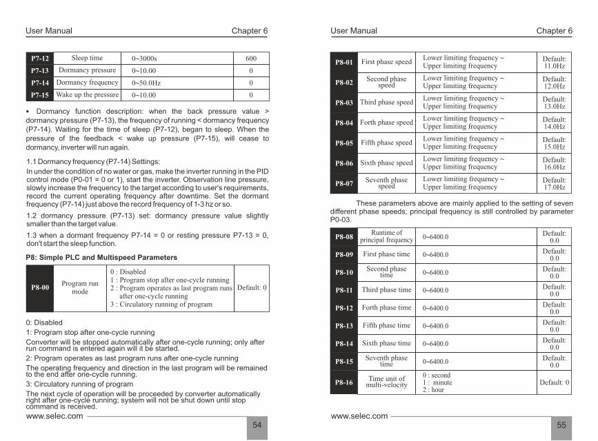
User ManualUser Manual Chapter 6 Chapter 6
55www.selec.comwww.selec.com
54
These parameters above are mainly applied to the setting of seven different phase speeds; principal frequency is still controlled by parameter P0-03.
First phase speed Default: 11.0HzP8-01
Lower limiting frequency ~ Upper limiting frequency
Second phasespeedP8-02
Lower limiting frequency ~ Upper limiting frequency
Third phase speedP8-03Lower limiting frequency ~ Upper limiting frequency
Forth phase speedP8-04Lower limiting frequency ~ Upper limiting frequency
Fifth phase speedP8-05Lower limiting frequency ~ Upper limiting frequency
Sixth phase speedP8-06Lower limiting frequency ~ Upper limiting frequency
Seventh phasespeedP8-07
Lower limiting frequency ~ Upper limiting frequency
Default: 12.0Hz
Default: 13.0Hz
Default: 14.0Hz
Default: 15.0Hz
Default: 16.0Hz
Default: 17.0Hz
Runtime ofprincipal frequency P8-08 Default:
0.0
First phase time Default: 0.0P8-09
Second phasetimeP8-10
Third phase timeP8-11
Forth phase timeP8-12
Fifth phase timeP8-13
Sixth phase timeP8-14
Seventh phasetimeP8-15
Default: 0.0
Default: 0.0
Default: 0.0
Default: 0.0
Default: 0.0
Default: 0.0
0~6400.0
0~6400.0
0~6400.0
0~6400.0
0~6400.0
0~6400.0
0~6400.0
0~6400.0
Time unit ofmulti-velocityP8-16 Default: 0
0 : second1 : minute2 : hour
Dormancy function description: when the back pressure value > dormancy pressure (P7-13), the frequency of running < dormancy frequency (P7-14). Waiting for the time of sleep (P7-12), began to sleep. When the pressure of the feedback < wake up pressure (P7-15), will cease to dormancy, inverter will run again.
1.1 Dormancy frequency (P7-14) Settings:
1.3 when a dormant frequency P7-14 = 0 or resting pressure P7-13 = 0, don't start the sleep function.
1.2 dormancy pressure (P7-13) set: dormancy pressure value slightly smaller than the target value.
In under the condition of no water or gas, make the inverter running in the PID control mode (P0-01 = 0 or 1), start the inverter. Observation line pressure, slowly increase the frequency to the target according to user's requirements, record the current operating frequency after downtime. Set the dormant frequency (P7-14) just above the record frequency of 1-3 hz or so.
Sleep time 0~3000s 600P7-12
Dormancy pressure
0~50.0Hz 0P7-14
P7-13
P7-15
Dormancy frequency
Wake up the pressure
0~10.00
0~10.00 0
0
P8: Simple PLC and Multispeed Parameters
Program runmode
0 : Disabled1 : Program stop after one-cycle running2 : Program operates as last program runs after one-cycle running3 : Circulatory running of program
Default: 0 P8-00
1: Program stop after one-cycle running
The next cycle of operation will be proceeded by converter automatically right after one-cycle running; system will not be shut down until stop command is received.
Converter will be stopped automatically after one-cycle running; only after run command is entered again will it be started.
0: Disabled
2: Program operates as last program runs after one-cycle running
The operating frequency and direction in the last program will be remained to the end after one-cycle running.
3: Circulatory running of program

User ManualUser Manual Chapter 6 Chapter 6
57www.selec.comwww.selec.com
56
7 6 5 4 3 2 1 0Parameter values = bit7×2 +bit6×2 +bit5×2 +bit4×2 +bit3×2 +bit2×2 +bit1×2 +bit0×2
7 6 5 4 3 2 1 0=0×2 +1×2 +0×2 +0×2 +1×2 +0×2 +1×2 +0×2=0+64+0+0+8+0+2+0 =74 Namely (01001010)2 = (74)10 Hence P8-17 should be set as 74
It’s mainly applied to the setting of Acc/Dec time for each program, which is preset by binary mode (16 bit). Parameter can be entered only after the binary value is converted into decimal value.
Take the following settings for example:
Parameter values= (0000000011100100) = (228)2 10
Hence the P8-18should be set as 228
P9 : Protection Function parameters
These two parameters are mainly applied to the setting of real-time relay protection of load motor. Effective thermal protection of motor can be achieved by setting this parameter correctly when rated current of motor is not matched with rated current of converter. Critical point of overload protection (motor) = (allowed max. load current / rated current of motor) * 100%
Timing for eachprogram's Acc-Dec Default: 0P8-18
0~65535 BIT 0~15 indicates the ACC/DECtime of 0~7
Options foroverload protection Default: 0P9-00
0 : Disabled
1 : Enabled
Critical point of overload protection
Default: 110%P9-01 50~120%
0123456789101112131415
0 0 0 0 0 0 0 0 1 1 1 0 0 1 0 0
152 142 132 122 112 102 92 82 72 62 52 42 32 22 12 02
Acc/Dec Time 0 of Principal Frequency
Acc/Dec time 1 of first programAcc/Dec time 2 of first program
Acc/Dec time 3 of first program
Acc/Dec time 0 of first program
Acc/Dec time 0 of first program
Acc/Dec time 0 of first program
Acc/Dec time 0 of first program
Weighted value
Binary set value
BIT
These parameters from P8-08 to P8-15 are mainly applied to the setting of run time for the velocity of each phase. Time unit can be preset by parameter P8-16.
It’s mainly applied to the setting of running directions for each program, which is preset by binary mode (8 bit). Parameter can be entered only after the binary value is converted into decimal value. Take the following settings for example:
Running directionsof programs Default: 0P8-17
0~255BIT 0~7 indicates 0~7 directions(0: Forward 1: Reverse)
P8-07
P8-04
P8-06
P8-05
P8-01
P8-02
P8-03
P8-03
P8-08 P8-09 P8-10 P8-11 P8-13 P8-14 P8-15P8-12
Frequency (Hz)
FWD
Time (t)
REV
Weighted value
BIT
Binary set value
0 : Forward
1 : Reverse
Running directions of Principle frequency: FWD
Running directions of first phase: REV
Running directions of second phase: FWD
Running directions of third phase: REV
Running directions of forth phase: FWD Running
directions of fifth phase: FWD
Running directions of sixth phase: REV
Running directions of seventh phase: FWD
0
72
0 0 0 0
62 52 42 32 22 12 02
1 11
7 5 4 2 06 13
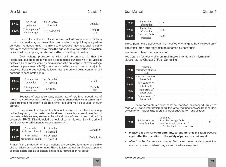
User ManualUser Manual Chapter 6 Chapter 6
59www.selec.comwww.selec.com
58
Latest fault information
0~20
Last two fault messages
These parameters above can’t be modified or changed; they are read-only.
Zero means there is no malfunction
1~20 stands for twenty different malfunctions; for detailed information, please refer to Chapter 7 “Fault Correcting”.
The latest three fault types can be recorded by converter:
Operatingfrequency of latest
fault Output current of
latest fault
These parameters above can’t be modified or changed; they are read-only. Status information about the latest malfunctions can be recorded by converter, including its operating frequency, current and voltage.
0: invalid 1: under-voltage fault automatic reset(unlimited)2~20: fault self-recovery alarm
0
• Please set this function carefully, to ensure that the fault occurs
again after the operation of the safety of person or equipment.
• After 2 ~ 20: frequency converter fault alarm automatically reset the
number of times. Under-voltage alarm reset is always valid.
P9-08
Latest fault information
0~20 P9-09
0~20 P9-10
P9-11
Bus voltage oflatest fault
Output state of latest fault
Input state oflatest fault
P9-15
P9-14
P9-13
P9-12
Fault since thereset function
P9-16
Over voltage protection function will be enabled so that the decreasing output frequency of converter can be slowed down if bus voltage detected by converter while running exceeds the critical point of over voltage defined by parameter P9-03(in comparison with standard bus voltage); if it’s detected that the bus voltage is lower than the critical point, converter will continue to decelerate again.
Due to the influence of inertia load, actual droop rate of motor’s rotational speed may be lower than droop rate of output frequency while converter is decelerating; meanwhile, electrodes may feedback electric energy to converter, which may raise the bus voltage of converter. If no action is taken in time, stripping may be caused by over voltage of busbar.
Because of excessive load, actual rate of rotational speed rise of motor may be lower than the rate of output frequency rise while converter is decelerating; if no action is taken in time, stripping may be caused by over current.
Over-current protection function will be enabled so that increasing output frequency of converter can be slowed down if bus current detected by converter while running exceeds the critical point of over current defined by parameter P9-05; if it’s detected that output current is lower than the critical point, converter will continue to accelerate again.
Phase-failure protection of input: options are selected to enable or disable phase-failure protection for input Phase-failure protection of output: options are selected to enable or disable phase-failure protection for output
Overloadprotection Default: 1P9-02
0 : Disabled
1 : Enabled
Critical point ofOver voltage
Default:118P9-03 110.0~150.0%
Over currentprotection Default: 1P9-04
0 : Disabled
1 : Enabled
Critical point of over-current
Default: 180P9-05 100~180%
Phase-failureprotection of input Default: 0P9-06
0 : Disabled
1 : Enabled
Phase-failureprotection of outputP9-07
0 : Disabled
1 : EnabledDefault: 0

User ManualUser Manual Chapter 6 Chapter 6
61www.selec.comwww.selec.com
60
0.0~Upper limiting frequency(P0-09)
These two parameters above are mainly applied to the setting of the detected value of output frequency (PA-11) as well as lagged value obtained after output is enabled.
Amplitude of detected
frequency FAR
Ÿ It’s mainly applied to the setting of amplitude detection for detected frequency.
FDT level value Default: 0.0Hz PA-11
0.0~FDT level value (PA-11)FDT lagged value Default: 0.0Hz PA-12
0.0~Upper limiting frequency(P0-09) Default: 0.0Hz PA-13
Setting frequencyafter regulation
Hopping frequency 2
Hopping frequency 1Amplitude of hopping
Signal of setting frequency
Amplitude of hopping
Amplitude of hopping
Amplitude of hopping
Output frequency
(Y1/Y2/RO)
FDT lagged valueFDT level
Frequency level detection FDT
Time
Time
ON
Prameters of PA Enhancements
Acceleration time 1 0.0~3600.0s Default: 20.0s
Deceleration time 1 0.0~3600.0s Default: 20.0s
Acceleration time 2 0.0~3600.0s Default: 20.0s
Deceleration time 2 0.0~3600.0s Default: 20.0s
Acceleration time 3 0.0~3600.0s Default: 20.0s
Deceleration time 3 0.0~3600.0s Default: 20.0s
Acc/Dec time 0~3 can be selected through different combinations of multi-functional digital input terminals.
Acc/Dec times are available to be selected, included three kinds of Acc/Dec times above, P0-04 and P0-05. They are all the same in definition; for detailed explanations, please refer to P0 series.
Jog acceleration time indicates the time for converter to accelerate from 0 Hz to maximum frequency (P0-08).
These two parameters above are applied to the definition of Acc/Dec time for jogging which can be started or stopped through direct starting or stop by decelerating.
Jog deceleration time indicates the time for converter to decelerate from maximum frequency (P0-08) to 0 Hz.
Converter can be kept away from the resonance point of load by the setting of hopping frequency. Two hopping points of frequency are set for this converter; if both of these two points are set as zero, this function will be disabled.
Actual operating frequency will be held at the boundary of hopping frequency which is closed to preset frequency when preset frequency is within the range of hopping frequency.
PA-00
PA-01
PA-02
PA-03
PA-04
PA-05
Jog acceleration time 0.0~3600.0s Default: 5.0s
Jog deceleration time 0.0~3600.0s
PA-06
PA-07
Hopping frequency 10.0~Upper limitingfrequency (P0-09) Default: 0.0HzPA-08
Hopping frequency 20.0~Upper limitingfrequency (P0-09)PA-09
Amplitude ofHopping frequency
0.0~Upper limitingfrequency (P0-09)PA-10
Default: 0.0Hz
Default: 0.0Hz
Default: 5.0s
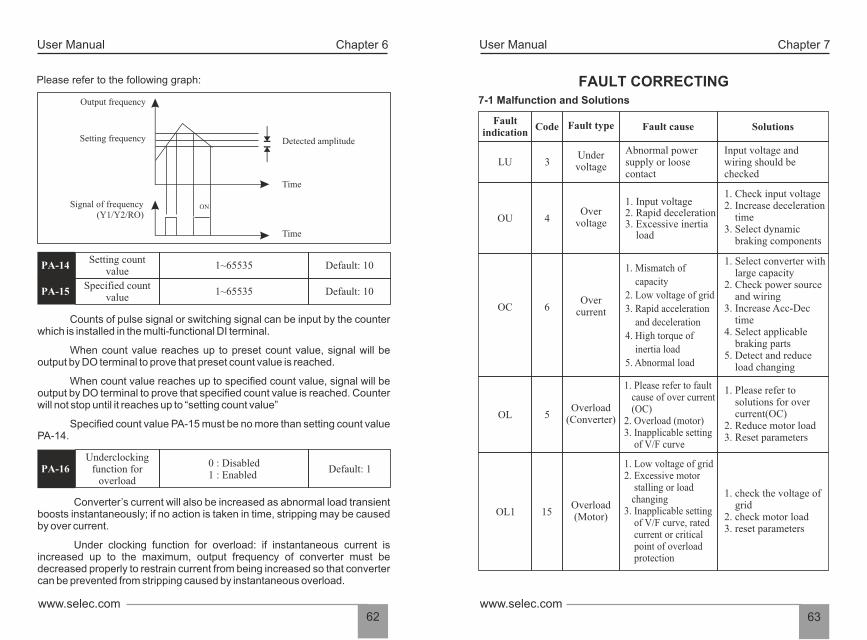
User ManualUser Manual Chapter 6 Chapter 7
63www.selec.comwww.selec.com
62
7-1 Malfunction and Solutions
FAULT CORRECTING
Faultindication
Code Fault type Fault cause Solutions
LU 3Undervoltage
Abnormal powersupply or loosecontact
Input voltage andwiring should bechecked
OU 4Over
voltage
1. Input voltage2. Rapid deceleration3. Excessive inertia load
1. Check input voltage2. Increase deceleration time3. Select dynamic braking components
OC 6Over
current
1. Mismatch of
capacity
2. Low voltage of grid
3. Rapid acceleration
and deceleration
4. High torque of
inertia load
5. Abnormal load
1. Select converter with large capacity2. Check power source and wiring3. Increase Acc-Dec time4. Select applicable braking parts5. Detect and reduce load changing
OL 5Overload
(Converter)
1. Please refer to fault cause of over current (OC)2. Overload (motor)3. Inapplicable setting of V/F curve
1. Please refer to solutions for over current(OC)2. Reduce motor load3. Reset parameters
OL1 15Overload(Motor)
1. Low voltage of grid2. Excessive motor stalling or load changing3. Inapplicable setting of V/F curve, rated current or critical point of overload protection
1. check the voltage of grid2. check motor load3. reset parameters
Setting count value
1~65535
Specified count value
Specified count value PA-15 must be no more than setting count value PA-14.
When count value reaches up to preset count value, signal will be output by DO terminal to prove that preset count value is reached.
Counts of pulse signal or switching signal can be input by the counter which is installed in the multi-functional DI terminal.
When count value reaches up to specified count value, signal will be output by DO terminal to prove that specified count value is reached. Counter will not stop until it reaches up to “setting count value”
0 : Disabled 1 : Enabled
Converter’s current will also be increased as abnormal load transient boosts instantaneously; if no action is taken in time, stripping may be caused by over current.
Under clocking function for overload: if instantaneous current is increased up to the maximum, output frequency of converter must be decreased properly to restrain current from being increased so that converter can be prevented from stripping caused by instantaneous overload.
Please refer to the following graph:
Default: 10PA-14
PA-15 Default: 10 1~65535
Underclockingfunction for
overloadDefault: 1PA-16
Output frequency
Setting frequency
Signal of frequency(Y1/Y2/RO)
Detected amplitude
Time
Time
ON
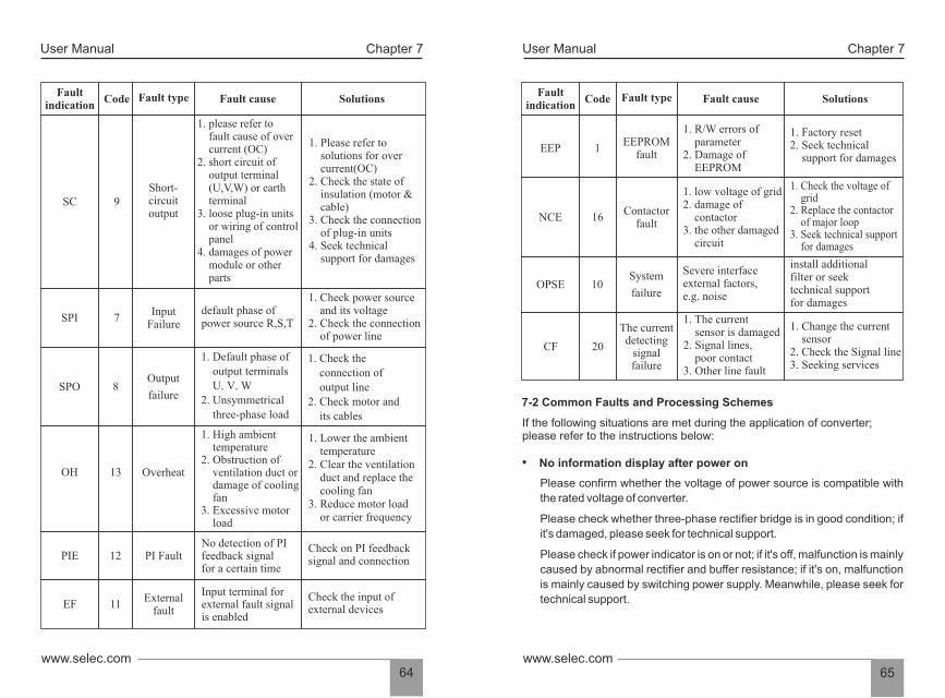
User ManualUser Manual Chapter 7 Chapter 7
65www.selec.comwww.selec.com
64
1. R/W errors of parameter2. Damage of EEPROM
OPSE 10 System
failure
Severe interfaceexternal factors, e.g. noise
install additional filter or seek technical support for damages
CF 20
The current detecting
signal failure
1. The current sensor is damaged 2. Signal lines, poor contact3. Other line fault
7-2 Common Faults and Processing Schemes
If the following situations are met during the application of converter; please refer to the instructions below:
• No information display after power on
Please check if power indicator is on or not; if it's off, malfunction is mainly
caused by abnormal rectifier and buffer resistance; if it's on, malfunction
is mainly caused by switching power supply. Meanwhile, please seek for
technical support.
Please confirm whether the voltage of power source is compatible with
the rated voltage of converter.
Please check whether three-phase rectifier bridge is in good condition; if
it's damaged, please seek for technical support.
Faultindication
Code Fault type Fault cause Solutions
EEP 1EEPROM
fault
1. Factory reset 2. Seek technical support for damages
1. low voltage of grid2. damage of contactor3. the other damaged circuit
NCE 16Contactor
fault
1. Check the voltage of grid2. Replace the contactor of major loop3. Seek technical support for damages
1. Change the current sensor2. Check the Signal line3. Seeking services
1. please refer to fault cause of over current (OC) 2. short circuit of output terminal (U,V,W) or earth terminal 3. loose plug-in units or wiring of control panel 4. damages of power module or other parts
Output
failure
Faultindication
Code Fault type Fault cause Solutions
SC 9Short-circuitoutput
1. Please refer to solutions for over current(OC)2. Check the state of insulation (motor & cable)3. Check the connection of plug-in units 4. Seek technical support for damages
SPI 7Input
Failuredefault phase ofpower source R,S,T
1. Check power source and its voltage2. Check the connection of power line
SPO 8
1. Default phase of output terminals U,V,W2. Unsymmetrical three-phase load
1. Check the connection of output line2. Check motor and its cables
OverheatOH 13
1. High ambient temperature2. Obstruction of ventilation duct or damage of cooling fan3. Excessive motor load
1. Lower the ambient temperature2. Clear the ventilation duct and replace the cooling fan3. Reduce motor load or carrier frequency
PIE 12 PI FaultNo detection of PIfeedback signalfor a certain time
Check on PI feedbacksignal and connection
EF 11External
fault
Input terminal forexternal fault signalis enabled
Check the input of external devices
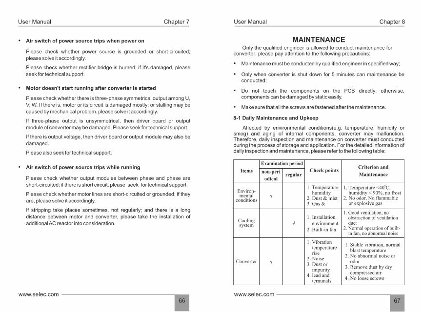
User ManualUser Manual Chapter 7 Chapter 8
67www.selec.comwww.selec.com
66
Only the qualified engineer is allowed to conduct maintenance for converter; please pay attention to the following precautions:
• Maintenance must be conducted by qualified engineer in specified way;
• Make sure that all the screws are fastened after the maintenance.
• Do not touch the components on the PCB directly; otherwise, components can be damaged by static easily.
• Only when converter is shut down for 5 minutes can maintenance be conducted;
8-1 Daily Maintenance and Upkeep
Affected by environmental conditions(e.g. temperature, humidity or smog) and aging of internal components, converter may malfunction. Therefore, daily inspection and maintenance on converter must conducted during the process of storage and application. For the detailed information of daily inspection and maintenance, please refer to the following table:
Items
Examination period
non-peri
odical regular
Check points Criterion and
Maintenance
Environ-mental
conditions
1. Temperature humidity 2. Dust & mist 3. Gas &
01. Temperature <40 C, humidity < 90%, no frost 2. No odor, No flammable or explosive gas
Cooling system
1. Installation environment 2. Built-in fan
1. Good ventilation, no obstruction of ventilation duct 2. Normal operation of built- in fan, no abnormal noise
MAINTENANCE
Converter
1. Vibration temperature rise 2. Noise 3. Dust or impurity 4. lead and terminals
1. Stable v ibration, n ormal blast temperature 2. No abnormal noise or odor 3. Remove dust by dry compressed air4. No loose screws
√
√
√
• Air switch of power source trips when power on
Please check whether rectifier bridge is burned; if it's damaged, please
seek for technical support.
Please check whether power source is grounded or short-circuited;
please solve it accordingly.
• Motor doesn't start running after converter is started
Please check whether there is three-phase symmetrical output among U,
V, W. If there is, motor or its circuit is damaged mostly; or stalling may be
caused by mechanical problem. please solve it accordingly.
If three-phase output is unsymmetrical, then driver board or output
module of converter may be damaged. Please seek for technical support.
If there is output voltage, then driver board or output module may also be
damaged.
Please also seek for technical support.
• Air switch of power source trips while running
Please check whether output modules between phase and phase are
short-circuited; if there is short circuit, please seek for technical support.
Please check whether motor lines are short-circuited or grounded; if they
are, please solve it accordingly.
If stripping take places sometimes, not regularly; and there is a long
distance between motor and converter, please take the installation of
additional AC reactor into consideration.

8-4 Product Warranty
Any of the following situations will be our company's responsibility, which will be considered and guaranteed:
• The warranty period for this product is 18months but only 12 months for final buyer. During the period, any damage or fault without any wrong operation will be our responsibility to fix, which is free of charge. Maintenance fee will be charged accordingly if warranty expires.
• Regarding the faults caused by the following points, extra fee will need to be charged as service fee:
1. Fault caused by faulty operation which is not in conformity with manual or specification
2. Fault caused by unauthorized maintenance modification;
3. Damage caused during the transportation or improper safekeeping;
4. Fault caused by misuse failure 5. As for the damages caused by fire, salt corrosion, gaseous corrosion, earthquake, storm, flood, thunder strike, abnormal voltage and other irresistible factor, despite of the expiration of warranty, any compensable maintenance service will be provided by our company for good.
User ManualUser Manual Chapter 8 Chapter 8
69www.selec.comwww.selec.com
68
Motor
1. Vibration a nd temperature rise 2. Noise
I/O parameters
1. Input voltage 2. Output current
8-2 Inspection and replacement of damageable parts
As for some of internal components, abrasion or performance degradation may be caused during use. To ensure stable and reliable operation, preventive maintenance on converter must be conducted. If necessary, please replace them:
Fan must be replaced after more than 20,000 hours' running.Electrolytic capacitor must be replaced after 30,000~40, 000 hours'running
√
√
1. Stable operation and normal temperature 2. No malfunction or abnormal noise
1. Input voltage is within specified range 2. Output current is lower than rated value
8-3 Storage
This product can't be taken out from box until it's about to be installed. To ensure that it's still valid for warranty and available for maintenance in the future during the period of storage, please pay attention to the following points:
• Relative humidity must be within the range between 0% and 95%; no condensation is permitted;
• It must be protected from caustic gas or liquid;
• Converter must be stored in a dry place where there is no dust;
0• Ambient temperature must be within the range between -20 C and060 C;
• It must be packed properly and put on the shelf or desk.
Items
Examination period
non-peri
odical regular
Check points Criterion and
Maintenance

User ManualUser Manual Chapter 9 Chapter 9
71www.selec.comwww.selec.com
70
9.2 Protocol Introductions
The protocol of FD200 Series Converter is a kind of serial &
asynchronous communication protocol with principal and subordinate
Modbus; there is only one device(host) could set up protocol (named "query
/command"), and the other devices(slave) can only response to the host's
"query /command" by sending data, or issue commands/instructions
according to the "query /command" from the host. The host herein mainly
refers to personal computer, industrial control facility or Programmable Logic
Controller (PLC); and the slave herein mainly refers to FD200 Series
Converter or the other control facilities with similar/same communication
protocol. The host can not only communicate with a certain
slave controller independently but also send broadcast message to all the
slave controllers. As to any independent access to the host's "query
/command", a message (called response) must be sent out from the slave
controller; however, regarding the broadcast message issued by the host, it's
not necessary for the slave controller to send feedback to the host.
9.3 Frame Structure
The data format of Modbus communication protocol applied in the
FD200 Series Converter is RTU mode (Remote Terminal Unit)
In the RTU mode, the format of each byte is as follow: encoding system
-8-bit binary system, there are two hexadecimal characters included in every
8-bit frame (hexadecimal characters include 0~9 & A~F). The transmission
of new frame will always be restarted with a interval of 3.5 bytes transmission
time. When it's connected with the Internet of which transmission rate is
calculated by Baud rate, 3.5-byte transmission time is easy to be controlled.
The data fields of transmission will be sent in sequence as below: slave
address - operating command code - data & CRC check word; and
transmission byte of each field are hexadecimal (0~9, A~F). The networking
devices will always monitor the operation of communication bus; when the
first domain (address information) is received, it will be confirmed again by
each networking device; when the transmission of last byte is done, there will
be a interval of 3.5 bytes transmission time to identify the end of this frame.
After that, transmission of new frame will be started again.
Modbus protocol is the main communication method applied in FD100 &
FD200 series converter with RS485 interfaces, which is compliant with
International Communication Standards. Centralized control can be
implemented by PC/PLC as well as superior controller to adapt specific
requirements for applications, including setting of control command,
operating frequency, modification of parameters for relevant function code,
monitoring of operating status or malfunction.
9.1 Protocol Content
Modbus, also known as serial communication protocol, has defined its
frames and format during the asynchronous transmission, including the
format of polling to the host, broadcast frames and response fames to slave
controller. The frames generated by the host included slave
address/broadcast address, executive command, data & error correction;
and the response of the slave controller has the similar frames as the host,
including confirmation of instructions, data feedback and error correction. If
any error happens when the slave controller receives the frames, or any
instruction requested by the host can't be done, it will generate a malfunction
frame and send feedback to the host.
9.1.1 Application mode
FD100 & FD200 series converter is compatible with control network equipped with RS485 bus which has single host & multiple slave controllers.
COMMUNICATION PROTOCOL
9.1.2 Bus Structure
The range of slave address should be 1~127; the number Zero stands
for broadcast communication address. Every single salve address on
the Internet is unique, which is the foundation of Modbus serial
communication.
Serial & asynchronous, half-duplex transmission -TXD and RXD can
be done at the same time by either the host or the slave controller
1 Hardware interface .
2. Transmission mode
3. System with single host & multiple slave controllers
separately, which means there are only one sender and one receiver at
a time. Data will be transmitted frame by frame in the format of
message during the serial & asynchronous communication.
RS485 hardware interface
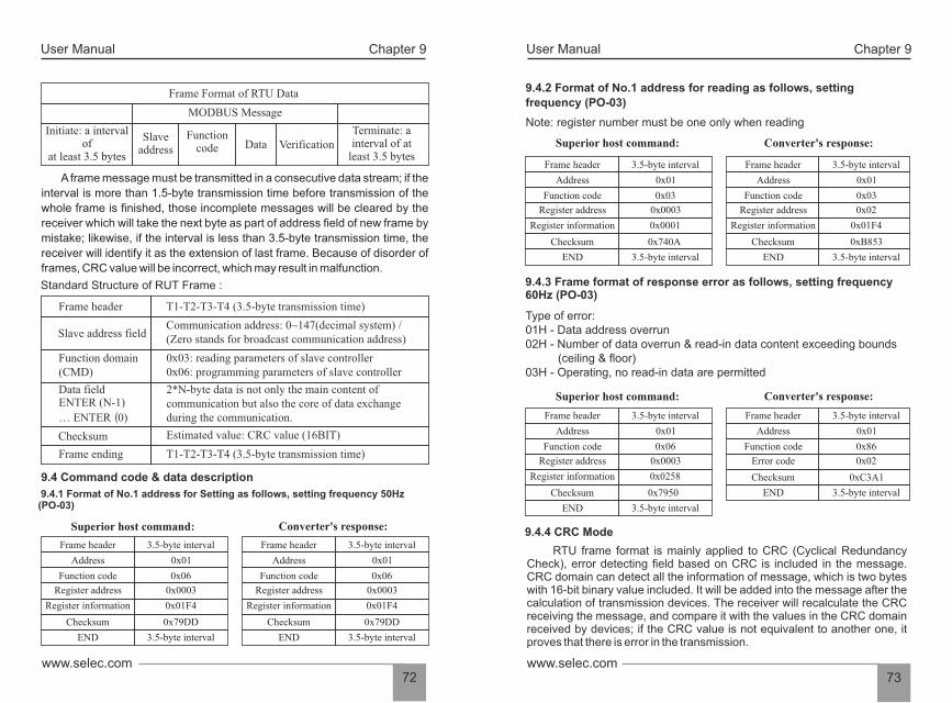
User ManualUser Manual Chapter 9 Chapter 9
73www.selec.comwww.selec.com
72
9.4.2 Format of No.1 address for reading as follows, setting
frequency (PO-03)
Note: register number must be one only when reading
Superior host command: Converter's response:
9.4.3 Frame format of response error as follows, setting frequency60Hz (PO-03)
Type of error: 01H - Data address overrun 02H - Number of data overrun & read-in data content exceeding bounds (ceiling & floor)03H - Operating, no read-in data are permitted
9.4.4 CRC Mode
RTU frame format is mainly applied to CRC (Cyclical Redundancy Check), error detecting field based on CRC is included in the message. CRC domain can detect all the information of message, which is two bytes with 16-bit binary value included. It will be added into the message after the calculation of transmission devices. The receiver will recalculate the CRC receiving the message, and compare it with the values in the CRC domain received by devices; if the CRC value is not equivalent to another one, it proves that there is error in the transmission.
Frame header
Address
Function code
Register address
Register information
Checksum
END
3.5-byte interval
0x01
0x03
0x0003
0x0001
0x740A
3.5-byte interval
Frame header
Address
Function code
Register address
Register information
Checksum
END
3.5-byte interval
0x01
0x03
0x02
0x01F4
0xB853
3.5-byte interval
Frame header
Address
Function code
Register address
Register information
Checksum
END
3.5-byte interval
0x01
0x06
0x0003
0x0258
0x7950
3.5-byte interval
Superior host command: Converter's response:
Frame header
Address
Function code
Error code
Checksum
END
3.5-byte interval
0x01
0x86
0x02
0xC3A1
3.5-byte interval
A frame message must be transmitted in a consecutive data stream; if the
interval is more than 1.5-byte transmission time before transmission of the
whole frame is finished, those incomplete messages will be cleared by the
receiver which will take the next byte as part of address field of new frame by
mistake; likewise, if the interval is less than 3.5-byte transmission time, the
receiver will identify it as the extension of last frame. Because of disorder of
frames, CRC value will be incorrect, which may result in malfunction.
Standard Structure of RUT Frame :
Frame Format of RTU Data
MODBUS Message
Initiate: a intervalof 3.5 bytesat least
Function code Data Verification
Terminate: a interval of at
least 3.5 bytes
Slave address
9.4 Command code & data description
9.4.1 Format of No.1 address for Setting as follows, setting frequency 50Hz(PO-03)
Superior host command: Converter's response:
Frame header T1-T2-T3-T4 (3.5-byte transmission time)
Slave address fieldCommunication address: 0~147(decimal system) / (Zero stands for broadcast communication address)
Function domain(CMD)
0x03: reading parameters of slave controller0x06: programming parameters of slave controller
Data fieldENTER (N-1)
… ENTER(0)
2*N-byte data is not only the main content of communication but also the core of data exchange during the communication.
Checksum Estimated value: CRC value (16BIT)
Frame ending T1-T2-T3-T4 (3.5-byte transmission time)
Frame header
Address
Function code
Register address
Register information
Checksum
END
3.5-byte interval
0x01
0x06
0x0003
0x01F4
0x79DD
3.5-byte interval
Frame header
Address
Function code
Register address
Register information
Checksum
END
3.5-byte interval
0x01
0x06
0x0003
0x01F4
0x79DD
3.5-byte interval
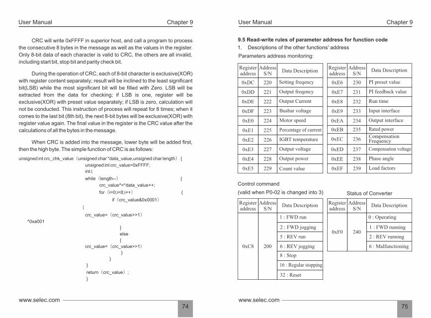
1. Descriptions of the other functions' address
Parameters address monitoring:
Control command
(valid when P0-02 is changed into 3) Status of Converter
User ManualUser Manual Chapter 9 Chapter 9
75www.selec.comwww.selec.com
74
9.5 Read-write rules of parameter address for function code
Register address
AddressS/N
Data Description
0xDC 220 Setting freqency
0xDD 221 Output freqency
0xDE 222 Output Current
0xDF 223 Busbar voltage
0xE0 224 Motor speed
0xE1 225 Percentage of current
0xE2 226 IGBT temperature
0xE3 227 Output voltage
0xE4 228 Output power
0xE5 229 Count value
Register address
AddressS/N
0xE6 230 PI preset value
0xE7 231 PI feedback value
0xE8 232 Run time
0xE9 233 Input interface
0xEA 234 Output interface
0xEB 235 Rated power
0xEC 236Compensation Frequency
0xED 237 Compensation voltage
0xEE 238 Phase angle
0xEF 239 Load factors
Register address
AddressS/N
0xC8 200
1 : FWD run
Data Description
Data Description
2 : FWD jogging
5 : REV run
6 : REV jogging
8 : Stop
16 : Regular stopping
32 : Reset
Register address
AddressS/N
0xF0 240
0 : Operating
Data Description
1 : FWD running
2 : REV running
6 : Malfunctioning
During the operation of CRC, each of 8-bit character is exclusive(XOR)
with register content separately; result will be inclined to the least significant
bit(LSB) while the most significant bit will be filled with Zero. LSB will be
extracted from the data for checking; if LSB is one, register will be
exclusive(XOR) with preset value separately; if LSB is zero, calculation will
not be conducted. This instruction of process will repeat for 8 times; when it
comes to the last bit (8th bit), the next 8-bit bytes will be exclusive(XOR) with
register value again. The final value in the register is the CRC value after the
calculations of all the bytes in the message.
When CRC is added into the message, lower byte will be added first,
then the high byte. The simple function of CRC is as follows:
CRC will write 0xFFFF in superior host, and call a program to process
the consecutive 8 bytes in the message as well as the values in the register.
Only 8-bit data of each character is valid to CRC, the others are all invalid,
including start bit, stop bit and parity check bit.
unsigned int crc_chk_value(unsigned char *data_value,unsigned char length)
crc_value=(crc_value>>1)
int i;
unsigned int crc_value=0xFFFF;
for(i=0;i<8;i++)
if(crc_value&0x0001)
else
while(length--)
crc_value^=*data_value++;
crc_value=(crc_value>>1)
0xa001
return(crc_value);
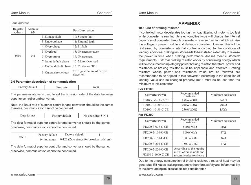
APPENDIX 10-1 List of braking resistor
If controlled motor decelerates too fast, or load jittering of motor is too fast
while converter is running, its electromotive force will charge the internal
capacitors of converter through converter's reverse function, which will rise
the voltage of power module and damage converter. However, this will be
restrained by converter's internal control according to the condition of
loading; additional braking resistor needs to be installed externally to release
the power in time when braking performance doesn't meet customers'
requirements. External braking resistor works by consuming energy which
will be consumed completely by power braking resistor; therefore, power and
resistance of braking resistor must be applicable and effective. Braking
resistors whose power and resistance value are as followed are
recommended to be applied to this converter. According to the condition of
loading, value can be changed properly; but it must be no less than the
minimum of this converter
FD200-3-075-C-CE 500W 90Ω 60Ω
FD200-3-100-C-CE 800W 60Ω 47Ω
FD200-3-150-C-CE 1000W 47Ω 36Ω
FD200-3-200-C-CE 1500W 36Ω 27Ω
FD200-3-250-C-CE~
FD200-3-1000-C-CE
According to the require-ments of brake units andrecommended to choose
For FD100
Due to the energy consumption of braking resistor, a mass of heat may be
generated if it keeps braking frequently; therefore, safety and Inflammability
of the surrounding must be taken into consideration
User ManualUser Manual Chapter 9 Chapter 10
77www.selec.comwww.selec.com
76
Converter Power Recommendedresistance Minimum resistance
FD100-1-0-10-C-CE 150W 400Ω 260Ω
FD100-1-0-20-C-CE
FD100-1-0-30-C-CE
200Ω
150Ω
200W 300Ω
250W 200Ω
For FD200
Converter Power Recommendedresistance Minimum resistance
9.6 Parameter description of communication
Note: the Baud rate of superior controller and converter should be the same; therwise, communication cannot be conducted.
The parameter above is used to set transmission rate of the data between
superior controller and converter.
Fault address
The data format of superior controller and converter should be the same;
otherwise, communication cannot be conducted.
Data Description Register address
AddressS/N
0xF1 241
1: Storage fault
3: Undervoltage
4: Overvoltage
5: Overload
6: Overcurrent
7: Input default phase
8: Output default phase
9: Output short circuit
10: System fault
11: External fault
12: PI fault
13: Overtemperature
14: Overcurrent
15: Motor Overload
16: Contactor OFF
20: Signal failure of currentdetection
9600Factory default Baud rate
No checking: 8-N-1Data format Factory default
The data format of superior controller and converter should be the same;
otherwise, communication cannot be conducted.
1P0-15
Factory default Factory default
Setting range 0-127 (Zero stands for broadcast address)

User ManualUser Manual Chapter 10 Chapter 10
79www.selec.comwww.selec.com
78
10.2.2 For VFD200 Series
Digital setting, Analog Voltage setting,Analog Current setting
Forward/Reverse, Jogging selection, MultiSpeed Control, Regular Stopping
Fault Alarm Output (250V/2A Contact),Open Collector Output
Over Current, Over Voltage, Under Voltage, Over heat, Overload, Phase loss
Parameters setting, Running status and Fault display
Temperature:10 ~ 40 Degree C, Humidity: < 90%, No condensation, IP20
Indoor, <1000m altitude above sea level
-20 ~ +60 Degree C
2<5.9 m/s (0.6g)
OperationCommands
Input Signal
Output signal
Operating conditions
Operating environment
Operations Area
Storage Temperature
Vibration
OperationFunction
Display
FrequencySetting
Keypad and External terminals
Protection Functions
Rated Power kW
Output current A
0.7 1.5 2.2 0.7 1.5 2.2 4 5.5 7.5 11 15 18.5 22 30
7 5.1 2.5 3.7 5.5 9 13 17 25 32 38 45 60
Rated Power kW
Output current A
37 45 55 75 90 110 132 160 185 200 220 250 280 315
75 90 110 150 176 210 250 300 340 380 420 470 520 585
Rated voltage V
Single-phase 220V
Three-phase 415V
Rated voltage V
Three-phase 415V
4.8
10.2.1 For VFD100
Three-Phase 415V
Single Phase 220V 50Hz/60Hz,3 Phase 415V 50Hz/60Hz.
187V to 253V for 1 phase & 320 to 460Vfor 3 Phase
Space Vector SVPWM and Flux Vector Control
0.1 ~ 400 Hz.
Digital setting 0.01%, Analog instruction 0.1% (Max frequency)
Digital instruction 0.1Hz, Analog instruction0.1 Hz.
0.0 ~ 3600 Sec. Four accelerate/deceleratetime settings available
Built-in program
Easy to set up a simple Automatic control system
Automatically Controlled Production line canbe achieved
G Type - 150% rated current for 1 min.P type - 120% rated current for 1 min
About 20% (with brake resistor is about 150%)
3 preset V/F mode and V/F program
Changes the V/F curve according to theload to save energy
Regulates the voltage automatically when-ever there is a change in grid voltage
Power supply
Rated input voltage/frequeny
Permissible frequencyfluctuation
Control mode
Frequency Controlrange
Frequency Accuracy
Frequency resolution
Accelerated/decele-ratedtime
Multi Speed running
Built-in PI
Built-in Counter
Overload Capacity
Braking torque
V/F mode
Automatic EnergySaving Operation
Automatic VoltageRegulation
Permissible voltagefluctuation
ControlCharact-eristic
±5%
Specifications
Rated Power kW
Output current A
Rated voltage VSingle-phase
220V
0.7 1.5 2.2 0.7 1.5 2.2
5 7 11 2.5 3.7 5.1
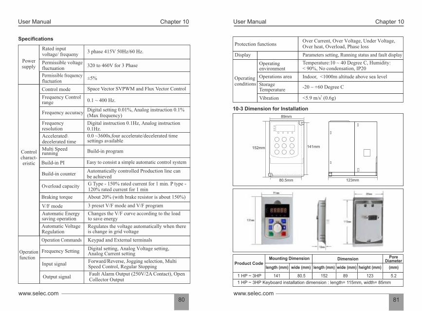
152mm
89mm
80.5mm
141mm
123mm
User ManualUser Manual Chapter 10 Chapter 10
81www.selec.comwww.selec.com
80
10-3 Dimension for Installation
Over Current, Over Voltage, Under Voltage,Over heat, Overload, Phase loss
Parameters setting, Running status and fault display
Temperature:10 ~ 40 Degree C, Humidity:< 90%, No condensation, IP20
Indoor, <1000m altitude above sea level
-20 ~ +60 Degree C
2<5.9 m/s (0.6g)
Operating conditions
Operating environment
Operations area
StorageTemperature
Vibration
Display
Protection functions
1 HP ~ 3HP
Product CodeMounting Dimension Dimension Pore
Diameter
length (mm) wide (mm) (mm)
80.5141 152 89 123 5.2
length (mm) wide (mm) height (mm)
1 HP ~ 3HP Keyboard installation dimension : length= 115mm, width= 85mm
Specifications
3 phase 415V 50Hz/60 Hz.
320 to 460V for 3 Phase
±5%
Space Vector SVPWM and Flux Vector Control
0.1 ~ 400 Hz.
Digital setting 0.01%, Analog instruction 0.1%(Max frequency)
Digital instruction 0.1Hz, Analog instruction 0.1Hz.
0.0 ~3600s,four accelerate/decelerated time settings available
Build-in program
Easy to consist a simple automatic control system
Power supply
Rated inputvoltage/ frequeny
Permissible frequencyfluctuation
Control mode
Frequency accuracy
Frequency resolution
Accelerated\decelerated time
Multi Speed running
Build-in PI
Permissible voltagefluctuation
Controlcharact-eristic
Digital setting, Analog Voltage setting, Analog Current setting
Forward/Reverse, Jogging selection, Multi Speed Control, Regular Stopping
Fault Alarm Output (250V/2A Contact), OpenCollector Output
Operationfunction
Keypad and External terminals
Frequency Controlrange
Build-in counter
Overload capacity
Braking torque
V/F mode
Automatic Energy saving operation
Automatic Voltage Regulation
Automatically controlled Production line canbe achieved
G Type - 150% rated current for 1 min. P type -120% rated current for 1 min
About 20% (with brake resistor is about 150%)
3 preset V/F mode and V/F program
Changes the V/F curve according to the loadto save energy
Regulates the voltage automatically when thereis change in grid voltage
Operation Commands
Input signal
Output signal
Frequency Setting
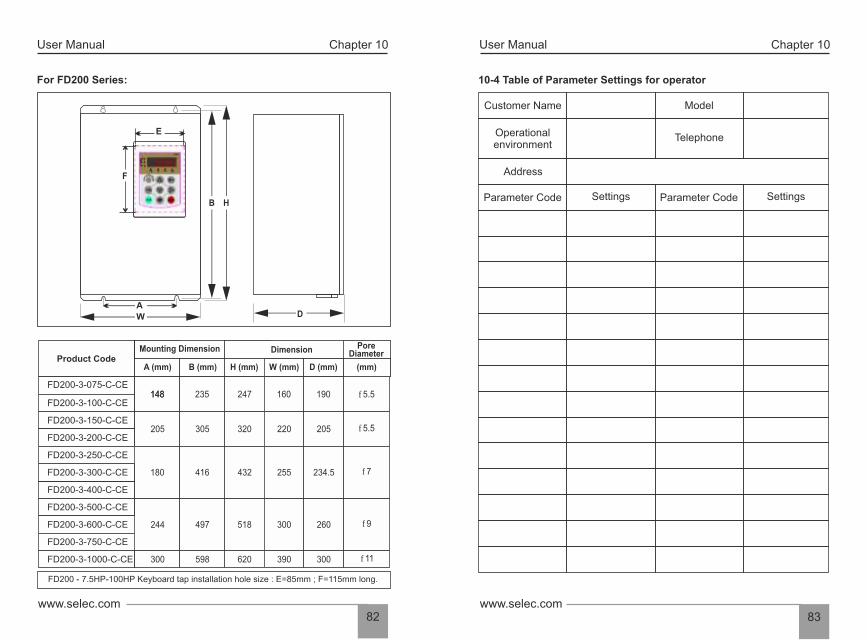
User ManualUser Manual Chapter 10 Chapter 10
83www.selec.comwww.selec.com
82
10-4 Table of Parameter Settings for operator
Customer Name Model
TelephoneOperational environment
Address
Parameter Code Settings Parameter Code SettingsB
WA
F
For FD200 Series:
FD200 - 7.5HP-100HP Keyboard tap installation hole size : E=85mm ; F=115mm long.
FD200-3-075-C-CE
Product Code
FD200-3-100-C-CE
FD200-3-150-C-CE
FD200-3-200-C-CE
FD200-3-300-C-CE
FD200-3-400-C-CE
FD200-3-500-C-CE
Mounting Dimension Dimension Pore Diameter
A (mm) B (mm) H (mm) W (mm) D (mm) (mm)
148
205
180 432
244 518 300 260497
235
305 320 220
416 255 234.5
205
148 247 160 190 f5.5
f5.5
f7
f9
FD200-3-250-C-CE
FD200-3-600-C-CE
FD200-3-750-C-CE
FD200-3-1000-C-CE 300 620 390 300598 f11
D
H
E