Embed Size (px)
DESCRIPTION
centrifugal pumps
Citation preview
Peerless Pump CompanyIndianapolis, IN 46207-7026
VERTICAL TURBINE PUMPS SECTION 115Page 0.1May 19, 2005
Discharge Head and Accessories
INDEXDATA & DIMENSIONSITEM PAGE
Type C & CHP 4
Type FA, FRA 7
Type S & SHP 5Application Data
Type UG 6Column Flange, Top - Data 14, 15Coupling, Flanged Top Shaft Coupling 27
Type C & CHP 10, 12
Type FA, FR, FRA 16, 16.1,17, 18
Type G, S & SHP 8, 9, 10, 11Dimensions
Type UG 13
Discharge Head/Product Description 2Flange, Top Column Dimensions 14, 15
General Head Data 1
Nut, Head Shaft with roller Thrust Bearing 33with Tank 35
Oiler Assembly Datawithout Tank 36
Packing Ring Size 28Pre-Lubrication Methods 75
Type FA, FR, FRA,FR 21, 22, 23, 24
Type C, CHP, G,GHP, S & SHP 19, 72Sole Plate, Steel
Type UG 26
Sub-Base, Cast Iron Type S & SHP 20
Stuffing Box Data 28
Stuffing Box Pictorial 29Tube Nut Pictorial (Std. & Packed Type) 30
Type C, CHP, G,GHP, S, SHP 31, 71
Two-Piece Head Shaft
Type UG 32
Subject to change without notice

Blank
Peerless Pump CompanyIndianapolis, IN 46207-7026
VERTICAL TURBINE PUMPS SECTION 115Page 1February 24, 2005
General Discharge Head Assembly Data
The Standard Head Assembly Includes The Following:
Discharge head casting or fabricated welded steel head, stuffing box or tube nut assembly, top
column flange and gasket. Fasteners for motor to head (only when complete pump is ordered),
stuffing box or tube nut assembly to head and top column flanged to head. Steel metal mesh hand
hole covers
Special Information Required When Ordering:
Motor BD, BX and CD dimensions, discharge piping size, well or floor opening size, head
room clearance. On underground discharge, distance between bottom of motor pedestal to
centerline of discharge. Clearance under head to accommodate top column flange and
clearance for below base elbow.
\\Subject to change without notice
SECTION 115Page 2February 24, 2005
VERTICAL TURBINE PUMPSDischarge Heads
Peerless Pump CompanyIndianapolis, IN 46207-7026
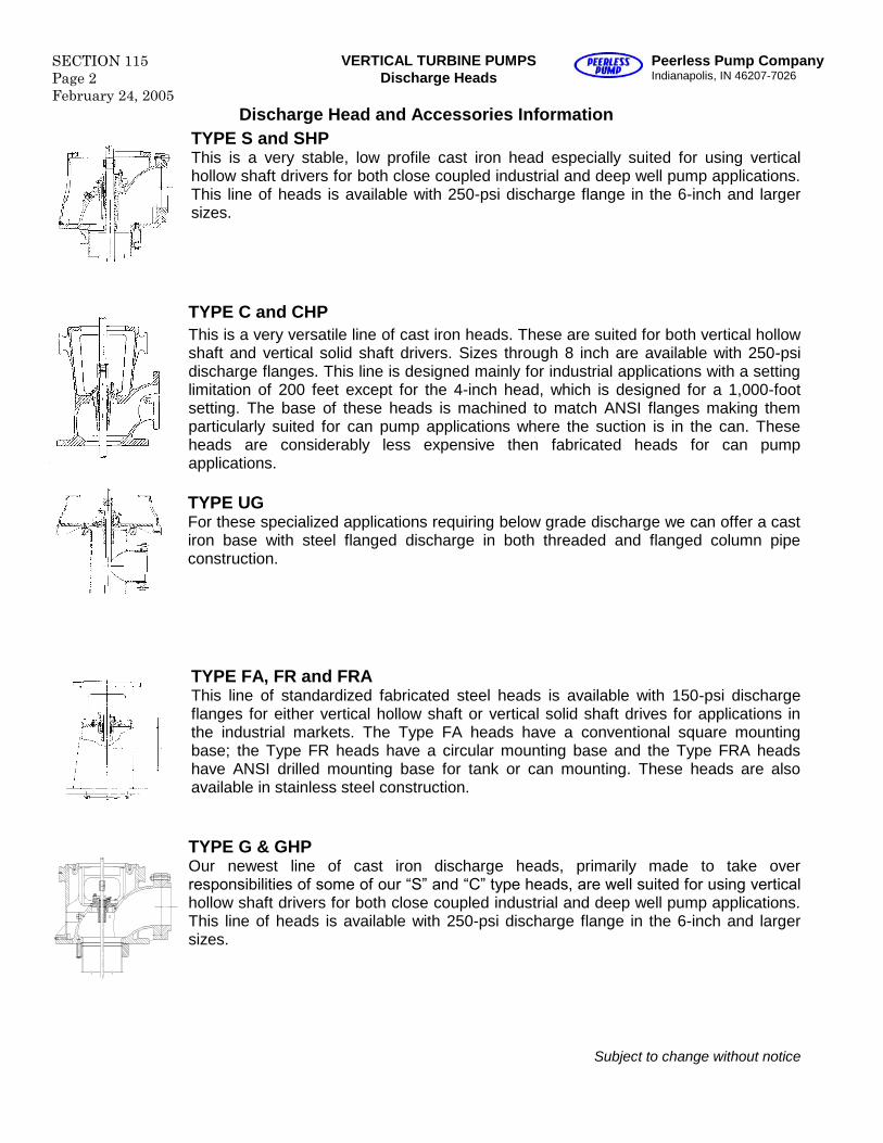
Discharge Head and Accessories InformationTYPE S and SHPThis is a very stable, low profile cast iron head especially suited for using verticalhollow shaft drivers for both close coupled industrial and deep well pump applications.This line of heads is available with 250-psi discharge flange in the 6-inch and largersizes.
TYPE C and CHPThis is a very versatile line of cast iron heads. These are suited for both vertical hollowshaft and vertical solid shaft drivers. Sizes through 8 inch are available with 250-psidischarge flanges. This line is designed mainly for industrial applications with a settinglimitation of 200 feet except for the 4-inch head, which is designed for a 1,000-footsetting. The base of these heads is machined to match ANSI flanges making themparticularly suited for can pump applications where the suction is in the can. Theseheads are considerably less expensive then fabricated heads for can pumpapplications.
TYPE UGFor these specialized applications requiring below grade discharge we can offer a castiron base with steel flanged discharge in both threaded and flanged column pipeconstruction.
TYPE FA, FR and FRAThis line of standardized fabricated steel heads is available with 150-psi dischargeflanges for either vertical hollow shaft or vertical solid shaft drives for applications inthe industrial markets. The Type FA heads have a conventional square mountingbase; the Type FR heads have a circular mounting base and the Type FRA headshave ANSI drilled mounting base for tank or can mounting. These heads are alsoavailable in stainless steel construction.
TYPE G & GHPOur newest line of cast iron discharge heads, primarily made to take overresponsibilities of some of our “S” and “C” type heads, are well suited for using vertical hollow shaft drivers for both close coupled industrial and deep well pump applications.This line of heads is available with 250-psi discharge flange in the 6-inch and largersizes.
Subject to change without notice
Peerless Pump CompanyIndianapolis, IN 46207-7026
VERTICAL TURBINE PUMPS SECTION 115Page 3February 24, 2005
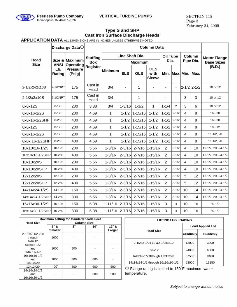
Type S and SHPCast Iron Surface Discharge Heads
APPLICATION DATA ALL DIMENSIONS ARE IN INCHES UNLESS OTHERWISE NOTED
Discharge Data Column Data
Line Shaft Dia.
Maximum
Oil TubeDia.
ColumnPipe Dia.Head
SizeSize &ANSILb.
Rating
MaximumOperatingPressure
(Psig)
StuffingBox
RegisterMinimum
ELS OLSOLSwith
SleeveMin. Max. Min. Max.
Motor FlangeBase Sizes
(B.D.)
2-1/2x2-/2x10S 2-1/2NPT 175 Cast inHead 3/4 - 1 - - - 2-1/2 2-1/2 10 or 12
2-1/2x3x10S 2-1/2NPT 175 Cast inHead 3/4 - 1 - - - 3 3 10 or 12
6x6x12S 6-125 200 3.88 3/4 1-3/16 1-1/2 1 1-1/4 2 3 6 10 or 12
6x8x16-1/2S 6-125 200 4.69 1 1-1/2 1-15/16 1-1/2 1-1/2 2-1/2 4 8 16 - 20
6x8x16-1/2SHP 6-250 400 4.69 1 1-1/2 1-15/16 1-1/2 1-1/2 2-1/2 4 8 16 - 20
8x8x12S 8-125 200 4.69 1 1-1/2 1-15/16 1-1/2 1-1/2 2-1/2 4 8 10 - 12
8x8x16-1/2S 8-125 200 4.69 1 1-1/2 1-15/16 1-1/2 1-1/2 2-1/2 4 8 16-1/2, 20
8x8x 16-1/2SHP 8-250 400 4.69 1 1-1/2 1-15/16 1-1/2 1-1/2 2-1/2 4 8 16-1/2, 20
10x10x16-1/2S 10-125 200 5.56 1-3/16 2-3/16 2-7/16 1-15/16 2 3-1/2 4 10 16-1/2, 20,-24-1/2
10x10x16-1/2SHP 10-250 400 5.56 1-3/16 2-3/16 2-7/16 1-15/16 2 3-1/2 4 10 16-1/2, 20,-24-1/2
10x10x20S 10-125 200 5.56 1-3/16 2-3/16 2-7/16 1-15/16 2 3-1/2 4 10 16-1/2, 20,-24-1/2
10x10x20SHP 10-250 400 5.56 1-3/16 2-3/16 2-7/16 1-15/16 2 3-1/2 4 10 16-1/2, 20,-24-1/2
12x12x20S 12-125 200 5.56 1-3/16 2-3/16 2-7/16 1-15/16 2 3-1/2 5 12 16-1/2, 20,-24-1/2
12x12x20SHP 12-250 400 5.56 1-3/16 2-3/16 2-7/16 1-15/16 2 3-1/2 5 12 16-1/2, 20,-24-1/2
14x14x24-1/2S 14-125 150 5.56 1-3/16 2-3/16 2-7/16 1-15/16 2 3-1/2 10 14 16-1/2, 20,-24-1/2
14x14x24-1/2SHP 14-250 300 5.56 1-3/16 2-3/16 2-7/16 1-15/16 2 3-1/2 10 14 16-1/2, 20,-24-1/2
16x16x30-1/2S 16-125 150 6.38 1-11/16 2-7/16 2-7/16 1-15/16 3 4 10 16 30-1/2
16x16x30-1/2SHP 16-250 300 6.38 1-11/16 2-7/16 2-7/16 1-15/16 3 4 10 16 30-1/2
Maximum setting for standard heads FeetColumn SizeHead Size
6" &Smaller
8" 10" 12" &Larger
2-1/2x2-1/2 x10through6x6x12
1000 - - -
6x8x16-1/2and
8x8x 16-1/21000 800 - -
10x10x16-1/2and
10x10x201000 800 600 -
12x12x20 100’ 800 600 50014x14x24-1/2
and16x16x30-1/2
- - 600 500
LIFTING LUG LOADING
Load Applied LbsHead Size
Gradually Suddenly
2-1/2x2-1/2x 10 &2-1/2x3x10 12000 3000
6x6x12 24000 6000
6x8x16-1/2 through 12x12x20 37500 9400
14x14x24-1/2 through 16x16x30-1/2 53000 13250
Flange rating is limited to 1500F maximum watertemperature.
Subject to change without notice
SECTION 115Page 4February 24, 2005
VERTICAL TURBINE PUMPS Peerless Pump CompanyIndianapolis, IN 46207-7026
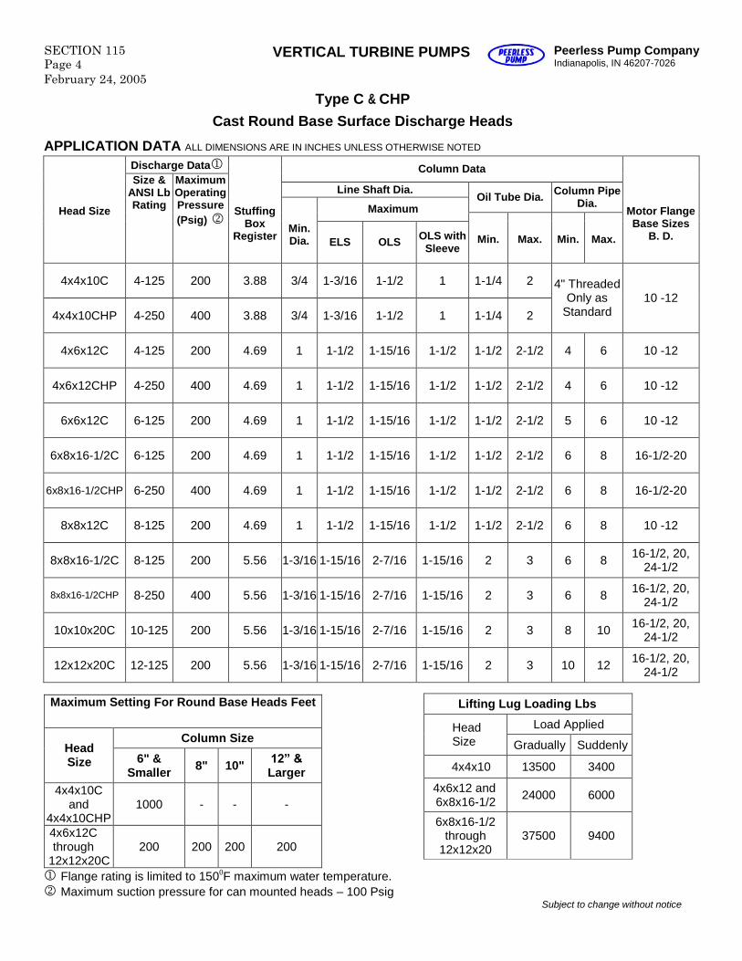
Type C & CHP
Cast Round Base Surface Discharge Heads
APPLICATION DATA ALL DIMENSIONS ARE IN INCHES UNLESS OTHERWISE NOTED
Discharge Data Column Data
Line Shaft Dia.Oil Tube Dia. Column Pipe
Dia.MaximumHead Size
Size &ANSI LbRating
MaximumOperatingPressure(Psig)
StuffingBox
RegisterMin.Dia. ELS OLS OLS with
SleeveMin. Max. Min. Max.
Motor FlangeBase Sizes
B. D.
4x4x10C 4-125 200 3.88 3/4 1-3/16 1-1/2 1 1-1/4 2
4x4x10CHP 4-250 400 3.88 3/4 1-3/16 1-1/2 1 1-1/4 2
4" ThreadedOnly as
Standard10 -12
4x6x12C 4-125 200 4.69 1 1-1/2 1-15/16 1-1/2 1-1/2 2-1/2 4 6 10 -12
4x6x12CHP 4-250 400 4.69 1 1-1/2 1-15/16 1-1/2 1-1/2 2-1/2 4 6 10 -12
6x6x12C 6-125 200 4.69 1 1-1/2 1-15/16 1-1/2 1-1/2 2-1/2 5 6 10 -12
6x8x16-1/2C 6-125 200 4.69 1 1-1/2 1-15/16 1-1/2 1-1/2 2-1/2 6 8 16-1/2-20
6x8x16-1/2CHP 6-250 400 4.69 1 1-1/2 1-15/16 1-1/2 1-1/2 2-1/2 6 8 16-1/2-20
8x8x12C 8-125 200 4.69 1 1-1/2 1-15/16 1-1/2 1-1/2 2-1/2 6 8 10 -12
8x8x16-1/2C 8-125 200 5.56 1-3/16 1-15/16 2-7/16 1-15/16 2 3 6 8 16-1/2, 20,24-1/2
8x8x16-1/2CHP 8-250 400 5.56 1-3/16 1-15/16 2-7/16 1-15/16 2 3 6 8 16-1/2, 20,24-1/2
10x10x20C 10-125 200 5.56 1-3/16 1-15/16 2-7/16 1-15/16 2 3 8 10 16-1/2, 20,24-1/2
12x12x20C 12-125 200 5.56 1-3/16 1-15/16 2-7/16 1-15/16 2 3 10 12 16-1/2, 20,24-1/2
Maximum Setting For Round Base Heads Feet
Column SizeHeadSize 6" &
Smaller 8" 10" 12” & Larger
4x4x10Cand
4x4x10CHP1000 - - -
4x6x12Cthrough
12x12x20C200 200 200 200
Flange rating is limited to 1500F maximum water temperature.Maximum suction pressure for can mounted heads –100 Psig
Subject to change without notice
Lifting Lug Loading Lbs
Load AppliedHeadSize Gradually Suddenly
4x4x10 13500 3400
4x6x12 and6x8x16-1/2 24000 6000
6x8x16-1/2through
12x12x2037500 9400
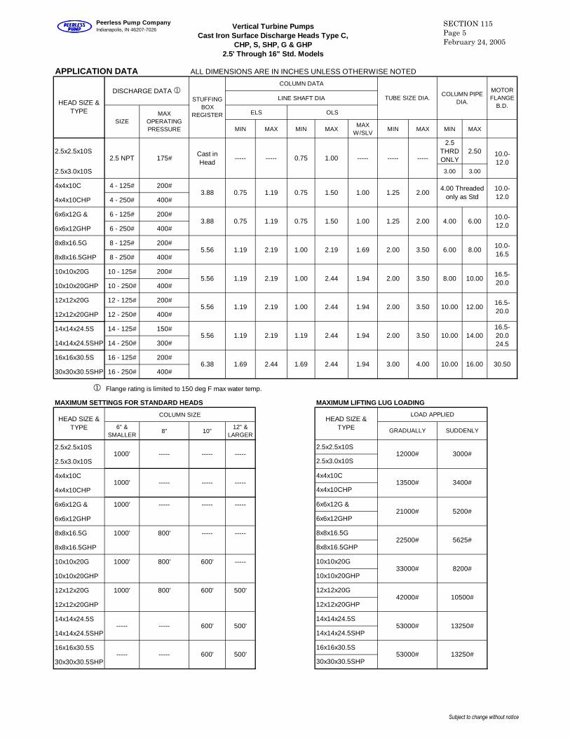
APPLICATION DATA ALL DIMENSIONS ARE IN INCHES UNLESS OTHERWISE NOTED
LINE SHAFT DIA
ELS OLS
MIN MAX MIN MAXMAX
W/SLVMIN MAX MIN MAX
2.5x2.5x10S2.5
THRDONLY
2.50
2.5x3.0x10S 3.00 3.00
4x4x10C 4 - 125# 200#
4x4x10CHP 4 - 250# 400#
6x6x12G & 6 - 125# 200#
6x6x12GHP 6 - 250# 400#
8x8x16.5G 8 - 125# 200#
8x8x16.5GHP 8 - 250# 400#
10x10x20G 10 - 125# 200#
10x10x20GHP 10 - 250# 400#
12x12x20G 12 - 125# 200#
12x12x20GHP 12 - 250# 400#
14x14x24.5S 14 - 125# 150#
14x14x24.5SHP 14 - 250# 300#
16x16x30.5S 16 - 125# 200#
30x30x30.5SHP 16 - 250# 400#
1 Flange rating is limited to 150 deg F max water temp.
MAXIMUM SETTINGS FOR STANDARD HEADS MAXIMUM LIFTING LUG LOADING
COLUMN SIZE
6" &SMALLER
8" 10"12" &
LARGER
2.5x2.5x10S
2.5x3.0x10S
4x4x10C
4x4x10CHP
6x6x12G & 1000' ----- ----- -----
6x6x12GHP
8x8x16.5G 1000' 800' ----- -----
8x8x16.5GHP
10x10x20G 1000' 800' 600' -----
10x10x20GHP
12x12x20G 1000' 800' 600' 500'
12x12x20GHP
14x14x24.5S
14x14x24.5SHP
16x16x30.5S
30x30x30.5SHP13250#
LOAD APPLIED
30x30x30.5SHP53000#
53000#
42000#
33000#
22500#
21000#
13500#
12000#
12x12x20GHP
14x14x24.5S
4x4x10CHP
6x6x12G &
6x6x12GHP
8x8x16.5G
14x14x24.5SHP
16x16x30.5S
8x8x16.5GHP
10x10x20G
10x10x20GHP
12x12x20G
MOTORFLANGE
B.D.
2.5x2.5x10S
2.5x3.0x10S
4x4x10C
GRADUALLY SUDDENLY
3000#
3400#
30.501.94
STUFFINGBOX
REGISTER
COLUMN DATA
TUBE SIZE DIA.COLUMN PIPE
DIA.
-----
1000' ----- ----- -----
6.38
600'----------
1000' ----- -----
600'
MAXOPERATINGPRESSURE
HEAD SIZE &TYPE
DISCHARGE DATA1
----- -----
2.5 NPT 175#
HEAD SIZE &TYPE
500'
500'
10.00 16.00
5200#
5625#
8200#
10500#
13250#
2.44 3.00 4.001.69 2.44 1.69
3.502.44 1.94 2.00 10.00 14.0016.5-20.024.5
10.00 12.0016.5-20.0
5.56 1.19 2.19 1.19
2.44 1.94 2.00 3.505.56 1.19 2.19 1.00
3.50 8.00 10.0016.5-20.0
6.00 8.0010.0-16.5
5.56 1.19 2.19 1.00 2.44 1.94 2.00
2.19 1.69 2.00 3.505.56 1.19 2.19 1.00
4.00 6.0010.0-12.0
10.0-12.0
1.50 1.00 1.25 2.003.88 0.75 1.19 0.75
1.19 0.75 1.50 1.00
----- -----10.0-12.0
4.00 Threadedonly as Std
1.25 2.00
HEAD SIZE &TYPE
SIZE
Cast inHead
----- ----- 0.75 1.00 -----
3.88 0.75
Vertical Turbine PumpsCast Iron Surface Discharge Heads Type C,
CHP, S, SHP, G & GHP2.5' Through 16" Std. Models
SECTION 115Page 5February 24, 2005
Peerless Pump CompanyIndianapolis, IN 46207-7026
Subject to change without notice
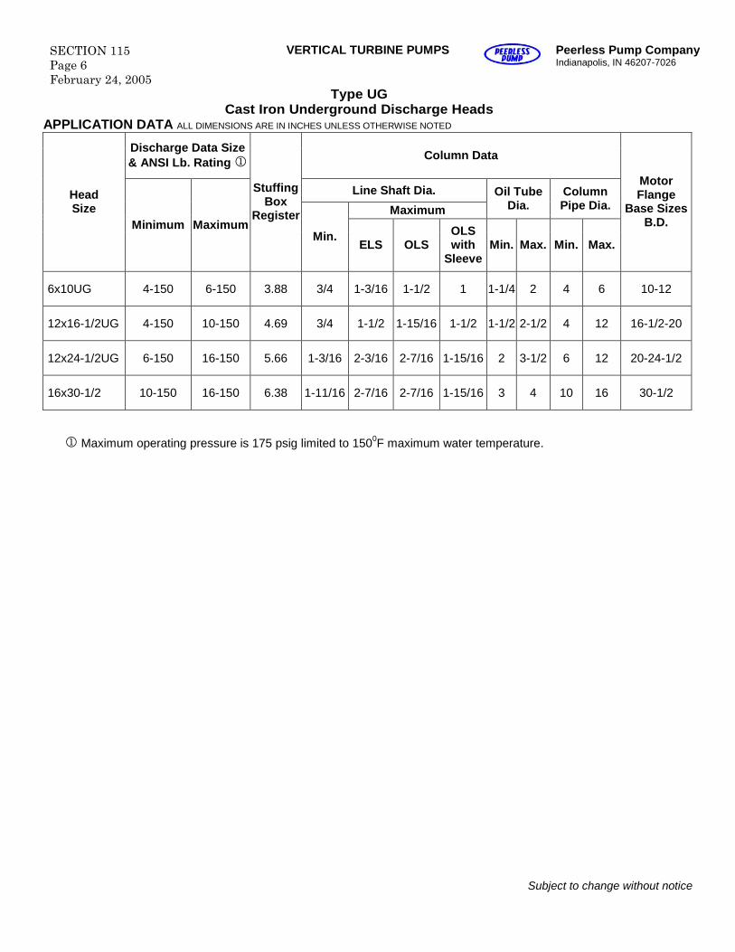
SECTION 115Page 6February 24, 2005
VERTICAL TURBINE PUMPS Peerless Pump CompanyIndianapolis, IN 46207-7026
Type UGCast Iron Underground Discharge Heads
APPLICATION DATA ALL DIMENSIONS ARE IN INCHES UNLESS OTHERWISE NOTED
Discharge Data Size& ANSI Lb. Rating Column Data
Line Shaft Dia.
Maximum
Oil TubeDia.
ColumnPipe Dia.
HeadSize
Minimum Maximum
StuffingBox
Register
Min.ELS OLS
OLSwith
SleeveMin. Max. Min. Max.
MotorFlange
Base SizesB.D.
6x10UG 4-150 6-150 3.88 3/4 1-3/16 1-1/2 1 1-1/4 2 4 6 10-12
12x16-1/2UG 4-150 10-150 4.69 3/4 1-1/2 1-15/16 1-1/2 1-1/2 2-1/2 4 12 16-1/2-20
12x24-1/2UG 6-150 16-150 5.66 1-3/16 2-3/16 2-7/16 1-15/16 2 3-1/2 6 12 20-24-1/2
16x30-1/2 10-150 16-150 6.38 1-11/16 2-7/16 2-7/16 1-15/16 3 4 10 16 30-1/2
Maximum operating pressure is 175 psig limited to 1500F maximum water temperature.
Subject to change without notice
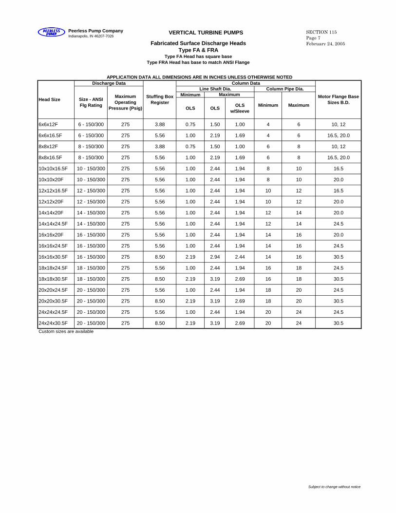
Minimum
OLS OLSOLS
w/Sleeve
6x6x12F 6 - 150/300 275 3.88 0.75 1.50 1.00 4 6 10, 12
6x6x16.5F 6 - 150/300 275 5.56 1.00 2.19 1.69 4 6 16.5, 20.0
8x8x12F 8 - 150/300 275 3.88 0.75 1.50 1.00 6 8 10, 12
8x8x16.5F 8 - 150/300 275 5.56 1.00 2.19 1.69 6 8 16.5, 20.0
10x10x16.5F 10 - 150/300 275 5.56 1.00 2.44 1.94 8 10 16.5
10x10x20F 10 - 150/300 275 5.56 1.00 2.44 1.94 8 10 20.0
12x12x16.5F 12 - 150/300 275 5.56 1.00 2.44 1.94 10 12 16.5
12x12x20F 12 - 150/300 275 5.56 1.00 2.44 1.94 10 12 20.0
14x14x20F 14 - 150/300 275 5.56 1.00 2.44 1.94 12 14 20.0
14x14x24.5F 14 - 150/300 275 5.56 1.00 2.44 1.94 12 14 24.5
16x16x20F 16 - 150/300 275 5.56 1.00 2.44 1.94 14 16 20.0
16x16x24.5F 16 - 150/300 275 5.56 1.00 2.44 1.94 14 16 24.5
16x16x30.5F 16 - 150/300 275 8.50 2.19 2.94 2.44 14 16 30.5
18x18x24.5F 18 - 150/300 275 5.56 1.00 2.44 1.94 16 18 24.5
18x18x30.5F 18 - 150/300 275 8.50 2.19 3.19 2.69 16 18 30.5
20x20x24.5F 20 - 150/300 275 5.56 1.00 2.44 1.94 18 20 24.5
20x20x30.5F 20 - 150/300 275 8.50 2.19 3.19 2.69 18 20 30.5
24x24x24.5F 20 - 150/300 275 5.56 1.00 2.44 1.94 20 24 24.5
24x24x30.5F 20 - 150/300 275 8.50 2.19 3.19 2.69 20 24 30.5
Custom sizes are available
Maximum
MaximumOperating
Pressure (Psig)
Size - ANSIFlg Rating
Head SizeStuffing Box
RegisterMotor Flange Base
Sizes B.D.
APPLICATION DATA ALL DIMENSIONS ARE IN INCHES UNLESS OTHERWISE NOTEDColumn DataDischarge Data
MaximumLine Shaft Dia. Column Pipe Dia.
Minimum
Peerless Pump CompanyIndianapolis, IN 46207-7026
VERTICAL TURBINE PUMPS
Fabricated Surface Discharge HeadsType FA & FRA
Type FA Head has square baseType FRA Head has base to match ANSI Flange
SECTION 115Page 7February 24, 2005
Subject to change without notice
BASEMOUNTING 4
HOLESNEMA DRIVER MOUNTING
BELOWBASE
CLEARANCEREQUIRED
AUXILLIARYCONNECTIONS
SEE NOTE 2
AJ DRILLING 4HOLES
STRADDLECENTERLINE
NOTE 3
DIABOLT
CIRCLECDIA SD
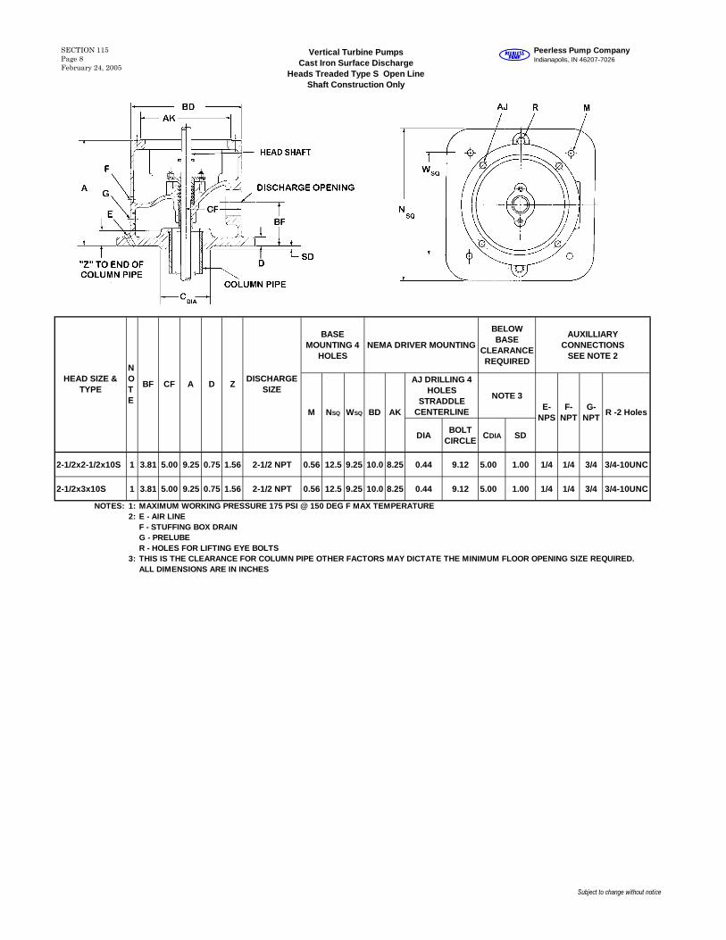
2-1/2x2-1/2x10S 1 3.81 5.00 9.25 0.75 1.56 2-1/2 NPT 0.56 12.5 9.25 10.0 8.25 0.44 9.12 5.00 1.00 1/4 1/4 3/4 3/4-10UNC
2-1/2x3x10S 1 3.81 5.00 9.25 0.75 1.56 2-1/2 NPT 0.56 12.5 9.25 10.0 8.25 0.44 9.12 5.00 1.00 1/4 1/4 3/4 3/4-10UNC
NOTES: 1: MAXIMUM WORKING PRESSURE 175 PSI @ 150 DEG F MAX TEMPERATURE2: E - AIR LINE
F - STUFFING BOX DRAING - PRELUBER - HOLES FOR LIFTING EYE BOLTS
3: THIS IS THE CLEARANCE FOR COLUMN PIPE OTHER FACTORS MAY DICTATE THE MINIMUM FLOOR OPENING SIZE REQUIRED.ALL DIMENSIONS ARE IN INCHES
HEAD SIZE &TYPE
E-NPS
F-NPT
G-NPT
ACFBF
NOTE
AK
ZD
M R -2 HolesNSQ WSQ BD
DISCHARGESIZE
Vertical Turbine PumpsCast Iron Surface Discharge
Heads Treaded Type S Open LineShaft Construction Only
SECTION 115Page 8February 24, 2005
Peerless Pump CompanyIndianapolis, IN 46207-7026
Subject to change without notice

DISCHARGE FLANGE ANSI FLATFACED
BASEMOUNTING 4
HOLESNEMA DRIVER MOUNTING
BELOW BASECLEARANCEREQUIRED
AUXILLIARYCONNECTIONS
SEE NOTE 5
SIZE &ANSI
T HOLE DRILLING &TAPPING STRADDLE
CENTERLINE
AJDRILLING/TAPPING4 HOLES STRADDLE
CTRLINE (AJ2DRILLING 4 HOLES
ON CTRLINE WHERESHOWN ONLY)
NOTE 6
RATING NO. THREADBOLT
CIRCLETHREAD
BOLTCIRCLE
CDIA
SD X Y
6x6x12S 1 6.50 8.00 13.69 0.75 6-125 LB 83/4-
10UNC9.50 0.75 15 13.25 12.0 8.25
(AJ) 0.44DIA (AJ2)3/8-16UNC
9.12 9.94 3.38 - - 3/4 1/2 3/4 N.A. 1/4
6x8x16.5S 1 7.75 10.25 14.75 1.25 6-125 LB 83/4-
10UNC9.50 1.00 20 18.00 16.5 13.50 5/8-11UNC 14.75 12.25 3.75 - - 3/4 3/8 3/4 1/2 1/4
6x8x16.5SHP 2 7.75 10.78 14.75 1.25 6-250 LB 123/4-
10UNC10.62 1.00 20 18.00 16.5 13.50 5/8-11UNC 14.75 12.25 3.75 - - 3/4 3/8 3/4 1/2 1/4
8x8x12S 1 7.00 9.00 14.75 0.88 8-125 LB 83/4-
10UNC11.75 0.88 17 15.00 12.0 8.25
(AJ) 0.44DIA (AJ2)3/8-16UNC
9.12 12.25 3.75 - - 3/4 1/2 3/4 1/2 1/4
8x8x16.5S 1 7.75 10.25 14.75 1.25 8-125 LB 83/4-
10UNC11.75 1.00 20 18.00 16.5 13.50 5/8-11UNC 14.75 12.25 3.75 - - 3/4 3/8 3/4 1/2 1/4
8x8x16.5SHP 2 7.75 10.88 14.75 1.25 8-250 LB 12 7/8-9UNC 13.00 1.00 20 18.00 16.5 13.50 5/8-11UNC 14.75 12.25 3.75 9.19 0.25 3/4 3/8 3/4 1/2 1/4
10x10x16.5S 1 9.00 10.25 18.00 1.50 10-125 LB 12 7/8-9UNC 14.25 1.00 20 18.00 16.5 13.50 5/8-11UNC 14.75 14.25 4.50 - - 3/4 3/8 3/4 1/2 1/4
10x10x16.5SHP 2 9.00 11.12 18.00 1.50 10-250 LB 16 1-8UNC 15.25 1.00 20 18.00 16.5 13.50 5/8-11UNC 14.75 14.25 4.50 - - 3/4 3/8 3/4 1/2 1/4
10x10x20S 1 9.00 10.25 18.00 1.50 10-125 LB 12 7/8-9UNC 14.25 1.00 20 18.00 20.0 13.505/8-11UNC
& 5/8-11UNC
14.75 &18.25
14.25 4.50 - - 3/4 3/8 3/4 1/2 1/4
10x10x20SHP 2 9.00 11.12 18.00 1.50 10-250 LB 16 1-8UNC 15.25 1.00 20 18.00 20.0 13.505/8-11UNC
& 5/8-11UNC
14.75 &18.25
14.25 4.50 - - 3/4 3/8 3/4 1/2 1/4
12x12x20S 1 10.50 12.25 21.00 1.75 12-125 LB 12 7/8-9UNC 17.00 1.00 23 21.00 20.0 13.50 5/8-11UNC 14.75 16.25 4.44 - - 3/4 3/8 1 1/2 1/4
12x12x20SHP 2 10.50 13.12 21.00 1.75 12-250 LB 161-1/8-7UNC
17.75 1.00 23 21.00 20.0 13.50 5/8-11UNC 14.75 16.25 4.44 - - 3/4 3/8 1 1/2 1/4
14x14x24.5S 3 11.50 14.75 22.25 1.75 14-125 LB 12 1-8UNC 18.75 1.00 28 25.00 24.5 13.50 5/8-11UNC 14.75 18.25 5.88 - - 3/4 3/8 1 1/2 1/4
14x14x24.5SHP 4 11.50 15.62 22.25 1.75 14-250 LB 201-1/8-7UNC
20.25 1.00 28 25.00 24.5 13.50 5/8-11UNC 14.75 18.25 5.88 13.5 0.50 3/4 3/8 1 1/2 1/4
NOTES: 1 MAXIMUM WORKING PRESSURE 200 PSI @ 150 DEG F MAX TEMPERATURE NOTE: 6 THIS IS THE CLEARANCE FOR TOP COLUMN FLANGE.
2 MAXIMUM WORKING PRESSURE 400 PSI @ 150 DEG F MAX TEMPERATURE OTHER FACTORS MAY DICTATE THE MINIMUM FLOOR
3 MAXIMUM WORKING PRESSURE 150 PSI @ 150 DEG F MAX TEMPERATURE OPENING SIZE REQUIRED.
4 MAXIMUM WORKING PRESSURE 300 PSI @ 150 DEG F MAX TEMPERATURE5 E - AIR LINE, F- STUFFING BOX DRAIN, G- PRELUBE OR PRESSURE TAP, H-DRAIN, J-PRESSURE TAP ALL DIMENSIONS ARE IN INCHES
HEAD SIZE &TYPE
NOTE
BF CF A D
M NSQ WSQ BD AK
DIS
CH
GF
LA
NG
EC
LE
AR
-AN
CE
J-NPT
E-NPS
F-NPT
G-NPT
H-NPS
Vertical Turbine PumpsCast Iron Surface Discharge Heads
S & SHP
SECTION 115Page 9February 24, 2005
Peerless Pump CompanyIndianapolis, IN 46207-7026
Subject to change without notice
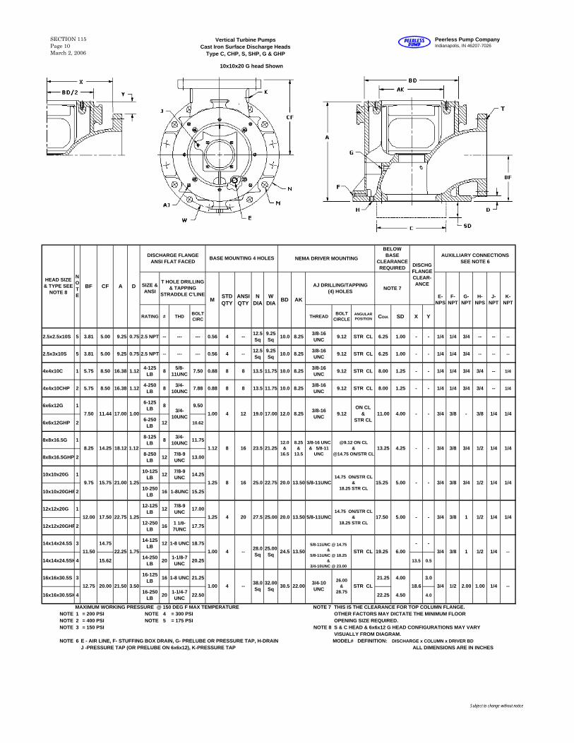
10x10x20 G head Shown
DISCHARGE FLANGE ANSI FLAT FACED NEMA DRIVER MOUNTING
BELOW BASE
CLEARANCE REQUIRED
AUXILLIARY CONNECTIONS SEE NOTE 6
SIZE & ANSI
AJ DRILLING/TAPPING (4) HOLES NOTE 7
RATING # THD BOLT CIRC THREAD BOLT
CIRCLEANGULAR POSITION CDIA SD X Y
2.5x2.5x10S 5 3.81 5.00 9.25 0.75 2.5 NPT -- --- --- 0.56 4 -- 12.5 Sq
9.25 Sq 10.0 8.25 3/8-16
UNC 9.12 STR CL 6.25 1.00 - - 1/4 1/4 3/4 -- -- --
2.5x3x10S 5 3.81 5.00 9.25 0.75 2.5 NPT -- --- --- 0.56 4 -- 12.5 Sq
9.25 Sq 10.0 8.25 3/8-16
UNC 9.12 STR CL 6.25 1.00 - - 1/4 1/4 3/4 -- -- --
4x4x10C 1 5.75 8.50 16.38 1.12 4-125 LB 8 5/8-
11UNC 7.50 0.88 8 8 13.5 11.75 10.0 8.25 3/8-16 UNC 9.12 STR CL 8.00 1.25 - - 1/4 1/4 3/4 3/4 -- 1/4
4x4x10CHP 2 5.75 8.50 16.38 1.12 4-250 LB 8 3/4-
10UNC 7.88 0.88 8 8 13.5 11.75 10.0 8.25 3/8-16 UNC 9.12 STR CL 8.00 1.25 - - 1/4 1/4 3/4 3/4 -- 1/4
6x6x12G 1 6-125 LB 8 9.50
6x6x12GHP 2 6-250 LB 12 10.62
8x8x16.5G 1 8-125 LB 8 3/4-
10UNC 11.75
8x8x16.5GHP 2 8-250 LB 12 7/8-9
UNC 13.00
10x10x20G 1 10-125 LB 12 7/8-9
UNC 14.25
10x10x20GHP2 10-250 LB 16 1-8UNC 15.25
12x12x20G 1 12-125 LB 12 7/8-9
UNC 17.00
12x12x20GHP2 12-250 LB 16 1 1/8-
7UNC 17.75
14x14x24.5S 3 14.75 14-125 LB 12 1-8 UNC 18.75 - -
14x14x24.5SH4 15.62 14-250 LB 20 1-1/8-7
UNC 20.25 13.5 0.5
16x16x30.5S 3 16-125 LB 16 1-8 UNC 21.25 21.25 4.00 3.0
16x16x30.5SH4 16-250 LB 20 1-1/4-7
UNC 22.50 22.25 4.50 4.0
MAXIMUM WORKING PRESSURE @ 150 DEG F MAX TEMPERATURE NOTE 7 THIS IS THE CLEARANCE FOR TOP COLUMN FLANGE. NOTE 1 = 200 PSI NOTE 4 = 300 PSI OTHER FACTORS MAY DICTATE THE MINIMUM FLOORNOTE 2 = 400 PSI NOTE 5 = 175 PSI OPENING SIZE REQUIRED.NOTE 3 = 150 PSI NOTE 8 S & C HEAD & 6x6x12 G HEAD CONFIGURATIONS MAY VARY
VISUALLY FROM DIAGRAM.NOTE 6 E - AIR LINE, F- STUFFING BOX DRAIN, G- PRELUBE OR PRESSURE TAP, H-DRAIN MODEL# DEFINITION: DISCHARGE x COLUMN x DRIVER BD
J -PRESSURE TAP (OR PRELUBE ON 6x6x12), K-PRESSURE TAP ALL DIMENSIONS ARE IN INCHES
H-NPS
J-NPT
K-NPT
HEAD SIZE & TYPE SEE
NOTE 8
DISCHG FLANGE CLEAR-ANCE
E-NPS
F-NPT
G-NPT
N DIA
W DIA BD AK
N O T E
M STD QTY
ANSI QTY
BF CF A D
7.50 11.44 17.00 1.00
8.25 14.25 18.12 1.12
9.75 15.75 21.00 1.25
12.00 17.50 22.75 1.25
11.50
12.75 20.00 21.50
22.25 1.75
3.50
1.003/4-10UNC
1.12
1.25
1.25
1.00
4 12 19.0 17.00 12.0 8.25 3/8-16 UNC 9.12
ON CL &
STR CL11.00 4.00 3/4- - 3/8 3/8 1/4 1/4-
4.25 - -8 16 23.5 21.25 1/4 1/412.0
& 16.5
8.25 &
13.5
3/8-16 UNC & 5/8-11
UNC3/4 3/8 3/4 1/213.25
8
4
16
20
25.0
27.5
22.75
25.00
20.0
20.0
13.50
13.50
15.25
17.50
5/8-11UNC
5/8-11UNC
3/8 3/4 1/25.00 - - 1/4 1/4
- - 3/4 3/8 1 1/2 1/4 1/4
3/8 1
T HOLE DRILLING & TAPPING
STRADDLE C'LINE
STR CL 19.25 6.0024.5 13.504 -- 1/2 1/4 --
1.00 4 -- 38.0 Sq
32.00 Sq 30.5 22.00 3/4
BASE MOUNTING 4 HOLES
3/4-10 UNC
26.00 &
28.75STR CL
3/428.0 Sq
25.00 Sq
3/4
5.00
--
5/8-11UNC @ 14.75 &
5/8-11UNC @ 18.25 &
3/4-10UNC @ 23.00
@9.12 ON CL &
@14.75 ON/STR CL
14.75 ON/STR CL &
18.25 STR CL
14.75 ON/STR CL &
18.25 STR CL
1/2 2.00 1.00 1/418.6
Vertical Turbine PumpsCast Iron Surface Discharge Heads
Type C, CHP, S, SHP, G & GHP
SECTION 115Page 10March 2, 2006
Peerless Pump CompanyIndianapolis, IN 46207-7026
Subject to change without notice
DISCHARGE FLANGE ANSI FLATFACED
BASE MOUNTING4 HOLES
NEMA DRIVER MOUNTINGBELOW BASECLEARANCEREQUIRED
SIZE &ANSI
T HOLE DRILLING &TAPPING STRADDLE
CENTERLINENOTE 3
RATING NO. THREADBOLT
CIRCLETHREAD
BOLTCIRCLE
C DIA SD
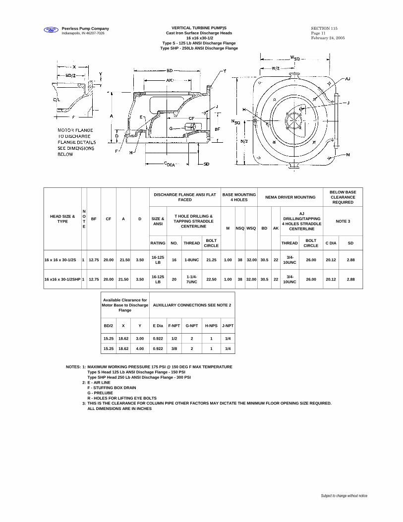
16 x 16 x 30-1/2S 1 12.75 20.00 21.50 3.5016-125
LB16 1-8UNC 21.25 1.00 38 32.00 30.5 22
3/4-10UNC
26.00 20.12 2.88
16 x16 x 30-1/2SHP 1 12.75 20.00 21.50 3.5016-125
LB20
1-1/4-7UNC
22.50 1.00 38 32.00 30.5 223/4-
10UNC26.00 20.12 2.88
Available Clearance forMotor Base to Discharge
FlangeAUXILLIARY CONNECTIONS SEE NOTE 2
15.25 18.62 3.00 0.922 1/2 2 1 1/4
15.25 18.62 4.00 0.922 3/8 2 1 1/4
NOTES: 1: MAXIMUM WORKING PRESSURE 175 PSI @ 150 DEG F MAX TEMPERATUREType S Head 125 Lb ANSI Dischage Flange - 150 PSIType SHP Head 250 Lb ANSI Dischage Flange - 300 PSI
2: E - AIR LINEF - STUFFING BOX DRAING - PRELUBER - HOLES FOR LIFTING EYE BOLTS
3: THIS IS THE CLEARANCE FOR COLUMN PIPE OTHER FACTORS MAY DICTATE THE MINIMUM FLOOR OPENING SIZE REQUIRED.ALL DIMENSIONS ARE IN INCHES
AJDRILLING/TAPPING
4 HOLES STRADDLECENTERLINE
F-NPT G-NPT H-NPS J-NPTBD/2 X Y E Dia
HEAD SIZE &TYPE
NOTE
BF CF
WSQ BD AK
A D
M NSQ
VERTICAL TURBINE PUMP)SCast Iron Surface Discharge Heads
16 x16 x30-1/2Type S - 125 Lb ANSI Discharge Flange
Type SHP - 250Lb ANSI Discharge Flange
SECTION 115Page 11February 24, 2005
Peerless Pump CompanyIndianapolis, IN 46207-7026
Subject to change without notice
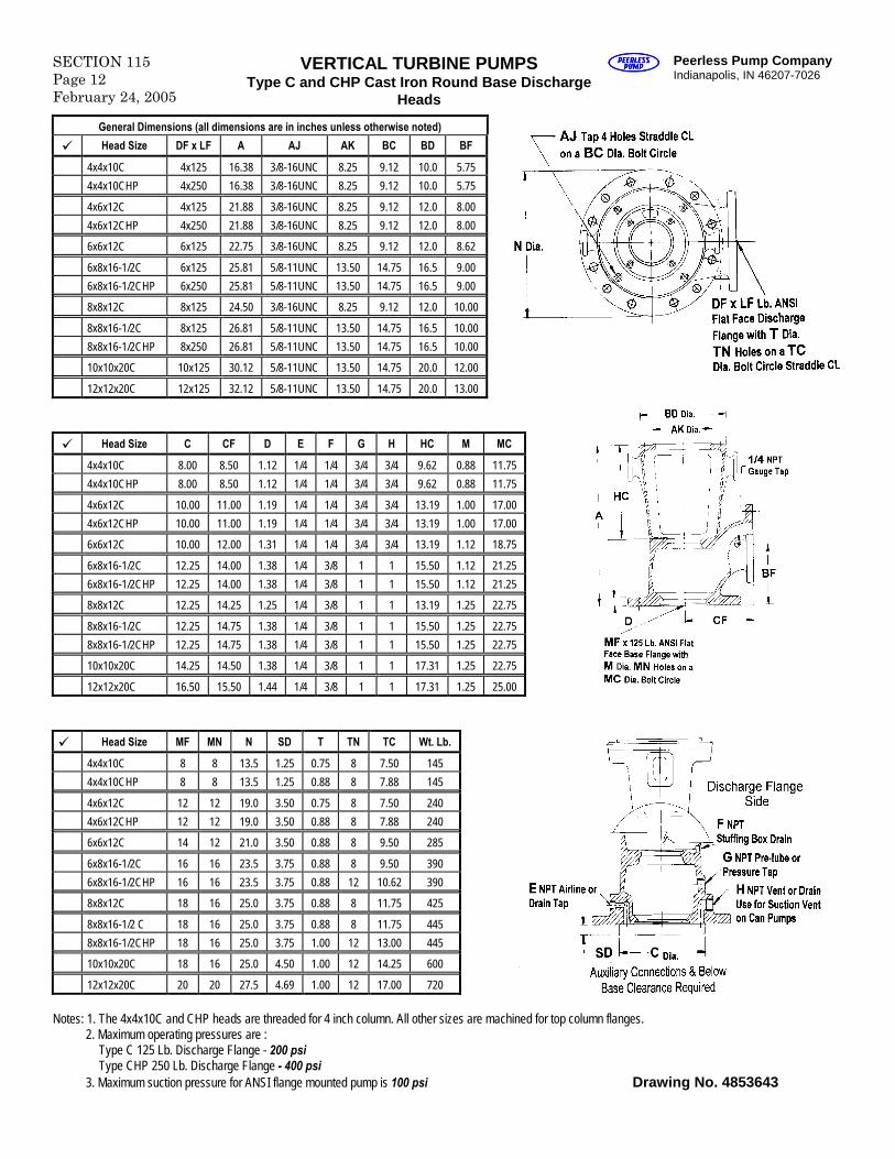
SECTION 115Page 12February 24, 2005
VERTICAL TURBINE PUMPSType C and CHP Cast Iron Round Base Discharge
Heads
Peerless Pump CompanyIndianapolis, IN 46207-7026
General Dimensions (all dimensions are in inches unless otherwise noted)
Head Size DF x LF A AJ AK BC BD BF
4x4x10C 4x125 16.38 3/8-16UNC 8.25 9.12 10.0 5.75
4x4x10CHP 4x250 16.38 3/8-16UNC 8.25 9.12 10.0 5.75
4x6x12C 4x125 21.88 3/8-16UNC 8.25 9.12 12.0 8.00
4x6x12CHP 4x250 21.88 3/8-16UNC 8.25 9.12 12.0 8.00
6x6x12C 6x125 22.75 3/8-16UNC 8.25 9.12 12.0 8.62
6x8x16-1/2C 6x125 25.81 5/8-11UNC 13.50 14.75 16.5 9.00
6x8x16-1/2CHP 6x250 25.81 5/8-11UNC 13.50 14.75 16.5 9.00
8x8x12C 8x125 24.50 3/8-16UNC 8.25 9.12 12.0 10.00
8x8x16-1/2C 8x125 26.81 5/8-11UNC 13.50 14.75 16.5 10.00
8x8x16-1/2CHP 8x250 26.81 5/8-11UNC 13.50 14.75 16.5 10.00
10x10x20C 10x125 30.12 5/8-11UNC 13.50 14.75 20.0 12.00
12x12x20C 12x125 32.12 5/8-11UNC 13.50 14.75 20.0 13.00
Head Size C CF D E F G H HC M MC
4x4x10C 8.00 8.50 1.12 1/4 1/4 3/4 3/4 9.62 0.88 11.75
4x4x10CHP 8.00 8.50 1.12 1/4 1/4 3/4 3/4 9.62 0.88 11.75
4x6x12C 10.00 11.00 1.19 1/4 1/4 3/4 3/4 13.19 1.00 17.00
4x6x12CHP 10.00 11.00 1.19 1/4 1/4 3/4 3/4 13.19 1.00 17.00
6x6x12C 10.00 12.00 1.31 1/4 1/4 3/4 3/4 13.19 1.12 18.75
6x8x16-1/2C 12.25 14.00 1.38 1/4 3/8 1 1 15.50 1.12 21.25
6x8x16-1/2CHP 12.25 14.00 1.38 1/4 3/8 1 1 15.50 1.12 21.25
8x8x12C 12.25 14.25 1.25 1/4 3/8 1 1 13.19 1.25 22.75
8x8x16-1/2C 12.25 14.75 1.38 1/4 3/8 1 1 15.50 1.25 22.75
8x8x16-1/2CHP 12.25 14.75 1.38 1/4 3/8 1 1 15.50 1.25 22.75
10x10x20C 14.25 14.50 1.38 1/4 3/8 1 1 17.31 1.25 22.75
12x12x20C 16.50 15.50 1.44 1/4 3/8 1 1 17.31 1.25 25.00
Head Size MF MN N SD T TN TC Wt. Lb.
4x4x10C 8 8 13.5 1.25 0.75 8 7.50 145
4x4x10CHP 8 8 13.5 1.25 0.88 8 7.88 145
4x6x12C 12 12 19.0 3.50 0.75 8 7.50 240
4x6x12CHP 12 12 19.0 3.50 0.88 8 7.88 240
6x6x12C 14 12 21.0 3.50 0.88 8 9.50 285
6x8x16-1/2C 16 16 23.5 3.75 0.88 8 9.50 390
6x8x16-1/2CHP 16 16 23.5 3.75 0.88 12 10.62 390
8x8x12C 18 16 25.0 3.75 0.88 8 11.75 425
8x8x16-1/2 C 18 16 25.0 3.75 0.88 8 11.75 445
8x8x16-1/2CHP 18 16 25.0 3.75 1.00 12 13.00 445
10x10x20C 18 16 25.0 4.50 1.00 12 14.25 600
12x12x20C 20 20 27.5 4.69 1.00 12 17.00 720
Notes: 1. The 4x4x10C and CHP heads are threaded for 4 inch column. All other sizes are machined for top column flanges.2. Maximum operating pressures are :
Type C 125 Lb. Discharge Flange - 200 psiType CHP 250 Lb. Discharge Flange - 400 psi
3. Maximum suction pressure for ANSI flange mounted pump is 100 psi Drawing No. 4853643
Peerless Pump CompanyIndianapolis, IN 46207-7026
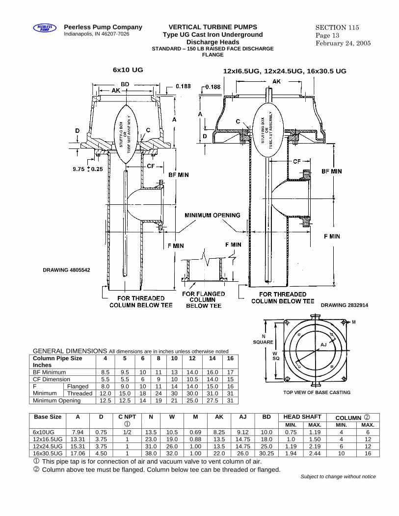
VERTICAL TURBINE PUMPSType UG Cast Iron Underground
Discharge HeadsSTANDARD –150 LB RAISED FACE DISCHARGE
FLANGE
SECTION 115Page 13February 24, 2005
GENERAL DIMENSIONS All dimensions are in inches unless otherwise notedColumn Pipe SizeInches
4 5 6 8 10 12 14 16
BF Minimum 8.5 9.5 10 11 13 14.0 16.0 17CF Dimension 5.5 5.5 6 9 10 10.5 14.0 15
Flanged 8.0 9.0 10 11 14 14.0 15.0 16FMinimum Threaded 12.0 15.0 18 24 30 30.0 31.0 31Minimum Opening 12.5 12.5 14 19 21 25.0 27.5 31
HEAD SHAFT COLUMN Base Size A D C NPT
N W M AK AJ BDMIN. MAX. MIN. MAX.
6x10UG 7.94 0.75 1/2 13.5 10.5 0.69 8.25 9.12 10.0 0.75 1.19 4 612x16.5UG 13.31 3.75 1 23.0 19.0 0.88 13.5 14.75 18.0 1.0 1.50 4 1212x24.5UG 15.31 3.75 1 31.0 26.0 1.00 13.5 14.75 25.0 1.19 2.19 6 1216x30.5UG 17.06 4.50 1 38.0 32.0 1.00 22.0 26.0 30.25 1.94 2.44 10 16 This pipe tap is for connection of air and vacuum valve to vent column of air.Column above tee must be flanged. Column below tee can be threaded or flanged.
Subject to change without notice
12xI6.5UG, 12x24.5UG, 16x30.5 UG
DRAWING 4805542
DRAWING 2832914
6x10 UG
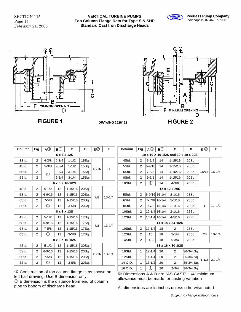
SECTION 115Page 14February 24, 2005
VERTICAL TURBINE PUMPSTop Column Flange Data for Type S & SHP
Standard Cast Iron Discharge Heads
Peerless Pump CompanyIndianapolis, IN 46207-7026
Column Fig. A B C D E F
6 x 6 x 12S
3Std. 2 4-3/8 9-3/4 1-1/2 15Sq.
4Std. 2 5-3/8 9-3/4 1-1/2 15Sq.
5Std. 2 9-3/4 3-1/4 15Sq.
6Std. 2
9-3/4 3-1/4 15Sq.
13/16 11
6 x 8 X 16-1/2S
4Std. 2 5-1/2 12 1-15/16 20Sq.
5Std. 2 6-9/16 12 1-15/16 20Sq.
6Std. 2 7-5/8 12 1-15/16 20Sq.
8Std. 2 12 3-5/8 20Sq.
7/8 13-1/4
8 x 8 x 12S
4Std. 2 5-1/2 12 1-15/16 17Sq.
5Std. 2 6-9/16 12 1-15/16 17Sq.
6Std. 2 7-5/8 12 1-15/16 17Sq.
8Std. 2 12 3-5/8 17Sq.
7/8 13-1/4
8 x 8 X 16-1/2S
4Std. 2 5-1/2 12 1-15/16 20Sq.
5Std. 2 6-9/16 12 1-15/16 20Sq.
6Std. 2 7-5/8 12 1-15/16 20Sq.
8Std. 2 12 3-5/8 20Sq.
15/16 13-1/4
Construction of top column flange is as shown onleft half drawing. Use B dimension only.E dimension is the distance from end of columnpipe to bottom of discharge head..
Column Fig. A B C D E F
10 x 10 X 16-1/2S and 10 x 10 x 20S
4Std. 2 5-1/2 14 1-15/16 20Sq.
5Std. 2 6-9/16 14 1-15/16 20Sq.
6Std. 2 7-5/8 14 1-15/16 20Sq.
8Std. 2 9-5/8 14 1-15/16 20Sq.
10Std. 2 14 4-3/8 20Sq.
15/16 15-1/4
12 x 12 x 20S
5Std. 2 6-9/16 16-1/4 2-1/16 23Sq.
6Std. 2 7- 7/8 16-1/4 2-1/16 23Sq.
8Std. 2 9-7/8 16-1/4 2-1/16 23Sq.
10Std. 2 12-1/4 16-1/4 2-1/16 23Sq.
12Std. 2 16-1/4 16-1/4 4-5/16 23Sq.
1 17-1/2
14 x 14 x 24-1/2S
10Std. 2 12-1/4 18 2 28Sq.
12Std. 2 18 18 5-1/4 28Sq.
14Std. 2 18 18 5-3/4 28Sq.
7/8 19-1/4
16 x 16 x 30-1/2S
10Std. 1 12-1/4 20 2 36-3/4 Sq.
12Std. 1 14-1/4 20 2 36-3/4 Sq.
14 O.D. 1 15-1/2 20 2 36-3/4 Sq.
16 O.D. 1 20 2-3/4 36-3/4 Sq.
1-1/2 21-1/4
Dimensions A & B are "AS CAST"; 1/4" minimumallowance must be made for casting variation
All dimensions are in inches unless otherwise noted
Subject to change without notice
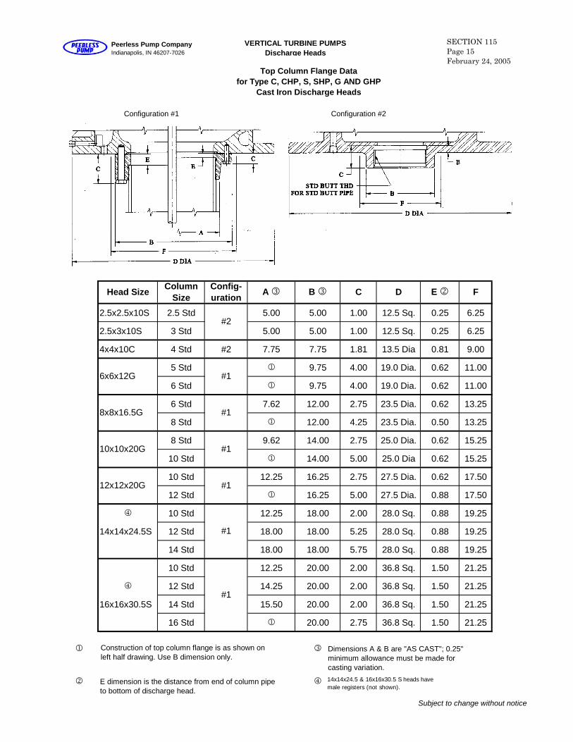
Configuration #2
2.5x2.5x10S 2.5 Std 5.00 5.00 1.00 12.5 Sq. 0.25 6.25
2.5x3x10S 3 Std 5.00 5.00 1.00 12.5 Sq. 0.25 6.25
4x4x10C 4 Std #2 7.75 7.75 1.81 13.5 Dia 0.81 9.00
5 Std 1 9.75 4.00 19.0 Dia. 0.62 11.00
6 Std 1 9.75 4.00 19.0 Dia. 0.62 11.00
6 Std 7.62 12.00 2.75 23.5 Dia. 0.62 13.25
8 Std 1 12.00 4.25 23.5 Dia. 0.50 13.25
8 Std 9.62 14.00 2.75 25.0 Dia. 0.62 15.25
10 Std 1 14.00 5.00 25.0 Dia 0.62 15.25
10 Std 12.25 16.25 2.75 27.5 Dia. 0.62 17.50
12 Std 1 16.25 5.00 27.5 Dia. 0.88 17.50
4 10 Std 12.25 18.00 2.00 28.0 Sq. 0.88 19.25
14x14x24.5S 12 Std 18.00 18.00 5.25 28.0 Sq. 0.88 19.25
14 Std 18.00 18.00 5.75 28.0 Sq. 0.88 19.25
10 Std 12.25 20.00 2.00 36.8 Sq. 1.50 21.25
4 12 Std 14.25 20.00 2.00 36.8 Sq. 1.50 21.25
16x16x30.5S 14 Std 15.50 20.00 2.00 36.8 Sq. 1.50 21.25
16 Std 1 20.00 2.75 36.8 Sq. 1.50 21.25
1 3
2 4
Subject to change without notice
12x12x20G
6x6x12G
8x8x16.5G
10x10x20G
Configuration #1
Head SizeColumn
SizeA3 F
Config-uration
#2
B3 C D E2
#1
#1
#1
#1
#1
#1
Construction of top column flange is as shown onleft half drawing. Use B dimension only.
E dimension is the distance from end of column pipeto bottom of discharge head.
Dimensions A & B are "AS CAST"; 0.25"minimum allowance must be made forcasting variation.
VERTICAL TURBINE PUMPSDischarge Heads
SECTION 115Page 15February 24, 2005
Peerless Pump CompanyIndianapolis, IN 46207-7026
Top Column Flange Datafor Type C, CHP, S, SHP, G AND GHP
Cast Iron Discharge Heads
14x14x24.5 & 16x16x30.5 S heads havemale registers (not shown).
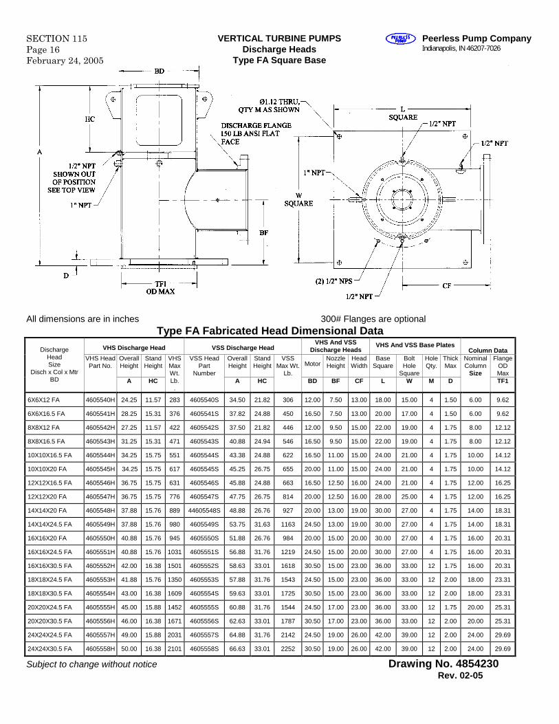
SECTION 115Page 16February 24, 2005
VERTICAL TURBINE PUMPSDischarge Heads
Type FA Square Base
Peerless Pump CompanyIndianapolis, IN 46207-7026
All dimensions are in inches 300# Flanges are optionalType FA Fabricated Head Dimensional Data
VHS Discharge Head VSS Discharge HeadVHS And VSS
Discharge HeadsVHS And VSS Base Plates
Column DataOverallHeight
StandHeight
OverallHeight
StandHeight Motor
NozzleHeight
HeadWidth
BaseSquare
BoltHole
Square
HoleQty.
ThickMax
FlangeODMax
DischargeHeadSize
Disch x Col x MtrBD
VHS HeadPart No.
A HC
VHSMaxWt.Lb..
VSS HeadPart
NumberA HC
VSSMax Wt.
Lb.BD BF CF L W M D
NominalColumn
SizeTF1
6X6X12 FA 4605540H 24.25 11.57 283 4605540S 34.50 21.82 306 12.00 7.50 13.00 18.00 15.00 4 1.50 6.00 9.62
6X6X16.5 FA 4605541H 28.25 15.31 376 4605541S 37.82 24.88 450 16.50 7.50 13.00 20.00 17.00 4 1.50 6.00 9.62
8X8X12 FA 4605542H 27.25 11.57 422 4605542S 37.50 21.82 446 12.00 9.50 15.00 22.00 19.00 4 1.75 8.00 12.12
8X8X16.5 FA 4605543H 31.25 15.31 471 4605543S 40.88 24.94 546 16.50 9.50 15.00 22.00 19.00 4 1.75 8.00 12.12
10X10X16.5 FA 4605544H 34.25 15.75 551 4605544S 43.38 24.88 622 16.50 11.00 15.00 24.00 21.00 4 1.75 10.00 14.12
10X10X20 FA 4605545H 34.25 15.75 617 4605545S 45.25 26.75 655 20.00 11.00 15.00 24.00 21.00 4 1.75 10.00 14.12
12X12X16.5 FA 4605546H 36.75 15.75 631 4605546S 45.88 24.88 663 16.50 12.50 16.00 24.00 21.00 4 1.75 12.00 16.25
12X12X20 FA 4605547H 36.75 15.75 776 4605547S 47.75 26.75 814 20.00 12.50 16.00 28.00 25.00 4 1.75 12.00 16.25
14X14X20 FA 4605548H 37.88 15.76 889 44605548S 48.88 26.76 927 20.00 13.00 19.00 30.00 27.00 4 1.75 14.00 18.31
14X14X24.5 FA 4605549H 37.88 15.76 980 4605549S 53.75 31.63 1163 24.50 13.00 19.00 30.00 27.00 4 1.75 14.00 18.31
16X16X20 FA 4605550H 40.88 15.76 945 4605550S 51.88 26.76 984 20.00 15.00 20.00 30.00 27.00 4 1.75 16.00 20.31
16X16X24.5 FA 4605551H 40.88 15.76 1031 4605551S 56.88 31.76 1219 24.50 15.00 20.00 30.00 27.00 4 1.75 16.00 20.31
16X16X30.5 FA 4605552H 42.00 16.38 1501 4605552S 58.63 33.01 1618 30.50 15.00 23.00 36.00 33.00 12 1.75 16.00 20.31
18X18X24.5 FA 4605553H 41.88 15.76 1350 4605553S 57.88 31.76 1543 24.50 15.00 23.00 36.00 33.00 12 2.00 18.00 23.31
18X18X30.5 FA 4605554H 43.00 16.38 1609 4605554S 59.63 33.01 1725 30.50 15.00 23.00 36.00 33.00 12 2.00 18.00 23.31
20X20X24.5 FA 4605555H 45.00 15.88 1452 4605555S 60.88 31.76 1544 24.50 17.00 23.00 36.00 33.00 12 1.75 20.00 25.31
20X20X30.5 FA 4605556H 46.00 16.38 1671 4605556S 62.63 33.01 1787 30.50 17.00 23.00 36.00 33.00 12 2.00 20.00 25.31
24X24X24.5 FA 4605557H 49.00 15.88 2031 4605557S 64.88 31.76 2142 24.50 19.00 26.00 42.00 39.00 12 2.00 24.00 29.69
24X24X30.5 FA 4605558H 50.00 16.38 2101 4605558S 66.63 33.01 2252 30.50 19.00 26.00 42.00 39.00 12 2.00 24.00 29.69
Subject to change without notice Drawing No. 4854230Rev. 02-05
Peerless Pump CompanyIndianapolis, IN 46207-7026
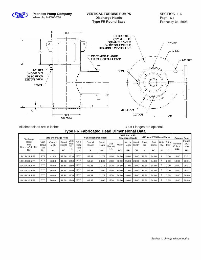
VERTICAL TURBINE PUMPSDischarge Heads
Type FR Round Base
SECTION 115Page 16.1February 24, 2005
All dimensions are in inches 300# Flanges are optionalType FR Fabricated Head Dimensional Data
VHS Discharge Head VSS Discharge HeadVHS And VSS
Discharge Heads VHS And VSS Base Plates Column Data
OverallHeight
StandHeight
OverallHeight
StandHeight Motor
NozzleHeight
HeadWidth
BaseDia.
BoltCircle
HoleQty.
ThickMax
FlangeODMax
DischargeHeadSize
Disch x Col x MtrBD
VHSHeadPartNo. A HC
VHSMaxWt.Lb..
VSSHeadPartNo. A HC
VSSMax Wt.
Lb. BD BF CF N BC M D
NominalColumn
SizeTF1
18X18X24.5 FR RTF 41.88 15.76 1230 RTF 57.88 31.75 1400 24.50 15.00 23.00 36.50 34.00 8 2.00 18.00 23.31
18X18X30.5 FR RTF 43.00 16.38 1350 RTF 59.63 33.00 1530 30.50 15.00 23.00 36.50 34.00 8 2.00 18.00 23.31
20X20X24.5 FR RTF 45.00 15.88 1390 RTF 60.88 31.75 1470 24.50 17.00 23.00 36.50 34.00 8 2.00 20.00 25.31
20X20X30.5 FR RTF 46.00 16.38 1500 RTF 62.63 33.00 1600 30.50 17.00 23.00 36.50 34.00 8 2.00 20.00 25.31
24X24X24.5 FR RTF 49.00 15.88 1670 RTF 64.88 31.75 1770 24.50 19.00 25.00 36.50 34.00 8 2.25 24.00 29.69
24X24X30.5 FR RTF 50.00 16.38 1740 RTF 66.63 33.00 1830 30.50 19.00 25.00 36.50 34.00 8 2.25 24.00 29.69
Subject to change without notice

Blank
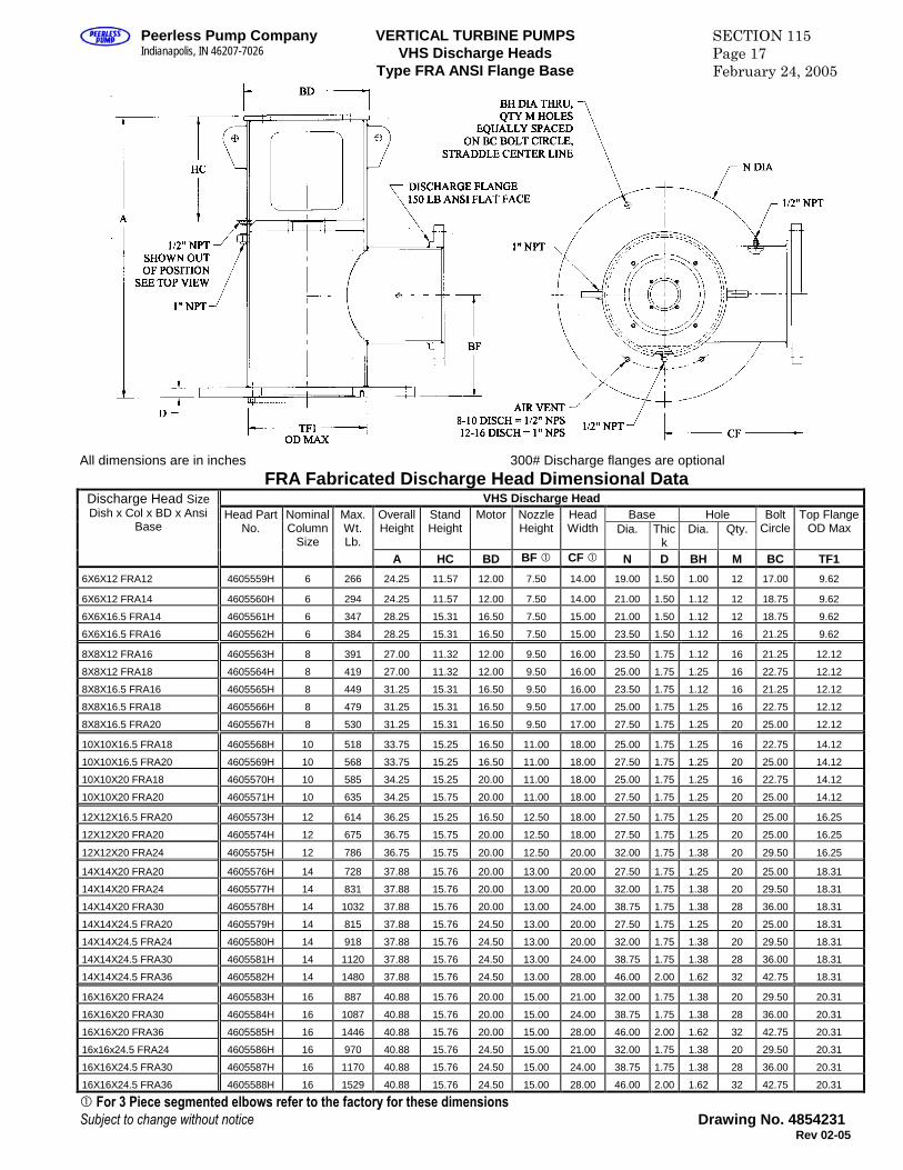
Peerless Pump CompanyIndianapolis, IN 46207-7026
VERTICAL TURBINE PUMPSVHS Discharge Heads
Type FRA ANSI Flange Base
SECTION 115Page 17February 24, 2005
All dimensions are in inches 300# Discharge flanges are optionalFRA Fabricated Discharge Head Dimensional Data
VHS Discharge HeadBase HoleOverall
HeightStandHeight
Motor NozzleHeight
HeadWidth Dia. Thic
kDia. Qty.
BoltCircle
Top FlangeOD Max
Discharge Head SizeDish x Col x BD x Ansi
BaseHead Part
No.NominalColumn
Size
Max.Wt.Lb.
A HC BD BF CF N D BH M BC TF1
6X6X12 FRA12 4605559H 6 266 24.25 11.57 12.00 7.50 14.00 19.00 1.50 1.00 12 17.00 9.62
6X6X12 FRA14 4605560H 6 294 24.25 11.57 12.00 7.50 14.00 21.00 1.50 1.12 12 18.75 9.62
6X6X16.5 FRA14 4605561H 6 347 28.25 15.31 16.50 7.50 15.00 21.00 1.50 1.12 12 18.75 9.62
6X6X16.5 FRA16 4605562H 6 384 28.25 15.31 16.50 7.50 15.00 23.50 1.50 1.12 16 21.25 9.62
8X8X12 FRA16 4605563H 8 391 27.00 11.32 12.00 9.50 16.00 23.50 1.75 1.12 16 21.25 12.12
8X8X12 FRA18 4605564H 8 419 27.00 11.32 12.00 9.50 16.00 25.00 1.75 1.25 16 22.75 12.12
8X8X16.5 FRA16 4605565H 8 449 31.25 15.31 16.50 9.50 16.00 23.50 1.75 1.12 16 21.25 12.12
8X8X16.5 FRA18 4605566H 8 479 31.25 15.31 16.50 9.50 17.00 25.00 1.75 1.25 16 22.75 12.12
8X8X16.5 FRA20 4605567H 8 530 31.25 15.31 16.50 9.50 17.00 27.50 1.75 1.25 20 25.00 12.12
10X10X16.5 FRA18 4605568H 10 518 33.75 15.25 16.50 11.00 18.00 25.00 1.75 1.25 16 22.75 14.12
10X10X16.5 FRA20 4605569H 10 568 33.75 15.25 16.50 11.00 18.00 27.50 1.75 1.25 20 25.00 14.12
10X10X20 FRA18 4605570H 10 585 34.25 15.25 20.00 11.00 18.00 25.00 1.75 1.25 16 22.75 14.12
10X10X20 FRA20 4605571H 10 635 34.25 15.75 20.00 11.00 18.00 27.50 1.75 1.25 20 25.00 14.12
12X12X16.5 FRA20 4605573H 12 614 36.25 15.25 16.50 12.50 18.00 27.50 1.75 1.25 20 25.00 16.25
12X12X20 FRA20 4605574H 12 675 36.75 15.75 20.00 12.50 18.00 27.50 1.75 1.25 20 25.00 16.25
12X12X20 FRA24 4605575H 12 786 36.75 15.75 20.00 12.50 20.00 32.00 1.75 1.38 20 29.50 16.25
14X14X20 FRA20 4605576H 14 728 37.88 15.76 20.00 13.00 20.00 27.50 1.75 1.25 20 25.00 18.31
14X14X20 FRA24 4605577H 14 831 37.88 15.76 20.00 13.00 20.00 32.00 1.75 1.38 20 29.50 18.31
14X14X20 FRA30 4605578H 14 1032 37.88 15.76 20.00 13.00 24.00 38.75 1.75 1.38 28 36.00 18.31
14X14X24.5 FRA20 4605579H 14 815 37.88 15.76 24.50 13.00 20.00 27.50 1.75 1.25 20 25.00 18.31
14X14X24.5 FRA24 4605580H 14 918 37.88 15.76 24.50 13.00 20.00 32.00 1.75 1.38 20 29.50 18.31
14X14X24.5 FRA30 4605581H 14 1120 37.88 15.76 24.50 13.00 24.00 38.75 1.75 1.38 28 36.00 18.31
14X14X24.5 FRA36 4605582H 14 1480 37.88 15.76 24.50 13.00 28.00 46.00 2.00 1.62 32 42.75 18.31
16X16X20 FRA24 4605583H 16 887 40.88 15.76 20.00 15.00 21.00 32.00 1.75 1.38 20 29.50 20.31
16X16X20 FRA30 4605584H 16 1087 40.88 15.76 20.00 15.00 24.00 38.75 1.75 1.38 28 36.00 20.31
16X16X20 FRA36 4605585H 16 1446 40.88 15.76 20.00 15.00 28.00 46.00 2.00 1.62 32 42.75 20.31
16x16x24.5 FRA24 4605586H 16 970 40.88 15.76 24.50 15.00 21.00 32.00 1.75 1.38 20 29.50 20.31
16X16X24.5 FRA30 4605587H 16 1170 40.88 15.76 24.50 15.00 24.00 38.75 1.75 1.38 28 36.00 20.31
16X16X24.5 FRA36 4605588H 16 1529 40.88 15.76 24.50 15.00 28.00 46.00 2.00 1.62 32 42.75 20.31
For 3 Piece segmented elbows refer to the factory for these dimensionsSubject to change without notice Drawing No. 4854231
Rev 02-05
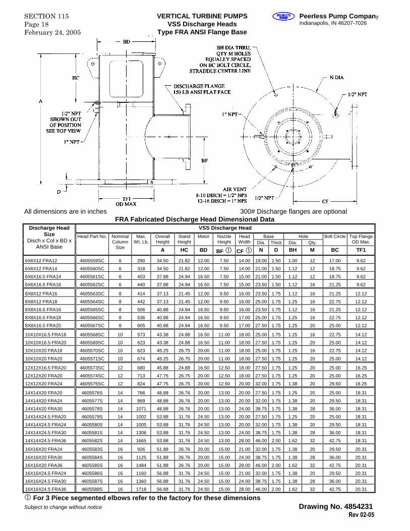
SECTION 115Page 18February 24, 2005
VERTICAL TURBINE PUMPSVSS Discharge Heads
Type FRA ANSI Flange Base
Peerless Pump CompanyIndianapolis, IN 46207-7026
All dimensions are in inches 300# Discharge flanges are optionalFRA Fabricated Discharge Head Dimensional Data
VSS Discharge Head
Base HoleOverallHeight
StandHeight
Motor NozzleHeight
HeadWidth Dia. Thick Dia. Qty.
Bolt Circle Top FlangeOD Max.
Discharge HeadSize
Disch x Col x BD xANSI Base
Head Part No. NominalColumn
Size
Max.Wt. Lb.
A HC BD BF CF N D BH M BC TF1
6X6X12 FRA12 4605559SC 6 290 34.50 21.82 12.00 7.50 14.00 19.00 1.50 1.00 12 17.00 9.62
6X6X12 FRA14 4605560SC 6 318 34.50 21.82 12.00 7.50 14.00 21.00 1.50 1.12 12 18.75 9.62
6X6X16.5 FRA14 4605561SC 6 403 37.88 24.94 16.50 7.50 15.00 21.00 1.50 1.12 12 18.75 9.62
6X6X16.5 FRA16 4605562SC 6 440 37.88 24.94 16.50 7.50 15.00 23.50 1.50 1.12 16 21.25 9.62
8X8X12 FRA16 4605563SC 8 414 37.13 21.45 12.00 9.50 16.00 23.50 1.75 1.12 16 21.25 12.12
8X8X12 FRA18 4605564SC 8 442 37.13 21.45 12.00 9.50 16.00 25.00 1.75 1.25 16 22.75 12.12
8X8X16.5 FRA16 4605565SC 8 506 40.88 24.94 16.50 9.50 16.00 23.50 1.75 1.12 16 21.25 12.12
8X8X16.5 FRA18 4605566SC 8 536 40.88 24.94 16.50 9.50 17.00 25.00 1.75 1.25 16 22.75 12.12
8X8X16.5 FRA20 4605567SC 8 605 40.88 24.94 16.50 9.50 17.00 27.50 1.75 1.25 20 25.00 12.12
10X10X16.5 FRA18 4605568SC 10 573 43.38 24.88 16.50 11.00 18.00 25.00 1.75 1.25 16 22.75 14.12
10X10X16.5 FRA20 4605569SC 10 623 43.38 24.88 16.50 11.00 18.00 27.50 1.75 1.25 20 25.00 14.12
10X10X20 FRA18 4605570SC 10 623 45.25 26.75 20.00 11.00 18.00 25.00 1.75 1.25 16 22.75 14.12
10X10X20 FRA20 4605571SC 10 674 45.25 26.75 20.00 11.00 18.00 27.50 1.75 1.25 20 25.00 14.12
12X12X16.5 FRA20 4605573SC 12 680 45.88 24.88 16.50 12.50 18.00 27.50 1.75 1.25 20 25.00 16.25
12X12X20 FRA20 4605574SC 12 713 47.75 26.75 20.00 12.50 18.00 27.50 1.75 1.25 20 25.00 16.25
12X12X20 FRA24 4605575SC 12 824 47.75 26.75 20.00 12.50 20.00 32.00 1.75 1.38 20 29.50 16.25
14X14X20 FRA20 4605576S 14 766 48.88 26.76 20.00 13.00 20.00 27.50 1.75 1.25 20 25.00 18.31
14X14X20 FRA24 4605577S 14 869 48.88 26.76 20.00 13.00 20.00 32.00 1.75 1.38 20 29.50 18.31
14X14X20 FRA30 4605578S 14 1071 48.88 26.76 20.00 13.00 24.00 38.75 1.75 1.38 28 36.00 18.31
14X14X24.5 FRA20 4605579S 14 1002 53.88 31.76 24.50 13.00 20.00 27.50 1.75 1.25 20 25.00 18.31
14X14X24.5 FRA24 4605580S 14 1005 53.88 31.76 24.50 13.00 20.00 32.00 1.75 1.38 20 29.50 18.31
14X14X24.5 FRA30 4605581S 14 1306 53.88 31.76 24.50 13.00 24.00 38.75 1.75 1.38 28 36.00 18.31
14X14X24.5 FRA36 4605582S 14 1665 53.88 31.76 24.50 13.00 28.00 46.00 2.00 1.62 32 42.75 18.31
16X16X20 FRA24 4605583S 16 926 51.88 26.76 20.00 15.00 21.00 32.00 1.75 1.38 20 29.50 20.31
16X16X20 FRA30 4605584S 16 1125 51.88 26.76 20.00 15.00 24.00 38.75 1.75 1.38 28 36.00 20.31
16X16X20 FRA36 4605585S 16 1484 51.88 26.76 20.00 15.00 28.00 46.00 2.00 1.62 32 42.75 20.31
16X16X24.5 FRA24 4605586S 16 1160 56.88 31.76 24.50 15.00 21.00 32.00 1.75 1.38 20 29.50 20.31
16X16X24.5 FRA30 4605587S 16 1360 56.88 31.76 24.50 15.00 24.00 38.75 1.75 1.38 28 36.00 20.31
16X16X24.5 FRA36 4605588S 16 1718 56.88 31.76 24.50 15.00 28.00 46.00 2.00 1.62 32 42.75 20.31
For 3 Piece segmented elbows refer to the factory for these dimensionsSubject to change without notice Drawing No. 4854231
Rev 02-05

All Dimensions are in inches
LxW Thick Id Qty Pattern Tap Pattern Qty
A B C D E F G H
2.5x2.5x10S 14.50 0.50 9.00 0.75 13.00 .375-16 UNC 9.25 SQ 4 2629916
2.5x3x10S 14.50 0.50 9.00 0.75 13.00 .375-16 UNC 9.25 SQ 4 2629916
4x4x10C 18.00 0.88 9.00 0.88 16.00 .750-10 UNC 11.75 8 2634417
6x6x12G 22.00 0.88 14.00 1.12 19.00 .875-9 UNC 17.00 12 4603250
8x8x16.5G 26.00 1.12 16.50 1.12 23.00 1.000-8 UNC 21.25 16 4602124
10x10x20G 30.00 1.12 20.00 1.12 27.00 1.125-7 UNC 22.75 16 4602127
12x12x20G 32.00 1.12 22.00 1.12 29.00 1.125-7 UNC 25.00 20 4602126
14x14x24.5S 36.00 1.00 24.50 1.25 32.00 .750-10 UNC 25.00 SQ 4 2629927
16x16x30.5S 42.00 1.00 28.00 1.25 39.00 .750-10 UNC 32.00 SQ 4 2629928
Subject to change without notice
Sole Plate PartNumber
Anchor Bolt
DischargeHead Size
Sole Plate Base Plate Hole
Sole Plates Dimensional Data
Sole Plate Datafor Type C, CHP, S, SHP, G AND GHP
Cast Iron Discharge Heads
VERTICAL TURBINE PUMPSDischarge Heads
SECTION 115Page 19February 24, 2005
Peerless Pump CompanyIndianapolis, IN 46207-7026
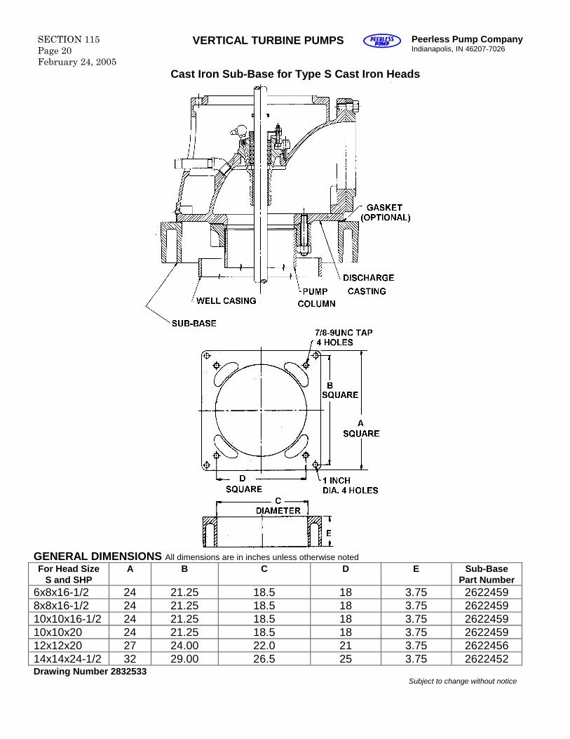
SECTION 115Page 20February 24, 2005
VERTICAL TURBINE PUMPS Peerless Pump CompanyIndianapolis, IN 46207-7026
Cast Iron Sub-Base for Type S Cast Iron Heads
GENERAL DIMENSIONS All dimensions are in inches unless otherwise notedFor Head Size
S and SHPA B C D E Sub-Base
Part Number6x8x16-1/2 24 21.25 18.5 18 3.75 26224598x8x16-1/2 24 21.25 18.5 18 3.75 262245910x10x16-1/2 24 21.25 18.5 18 3.75 262245910x10x20 24 21.25 18.5 18 3.75 262245912x12x20 27 24.00 22.0 21 3.75 262245614x14x24-1/2 32 29.00 26.5 25 3.75 2622452Drawing Number 2832533
Subject to change without notice
Peerless Pump CompanyIndianapolis, IN 46207-7026
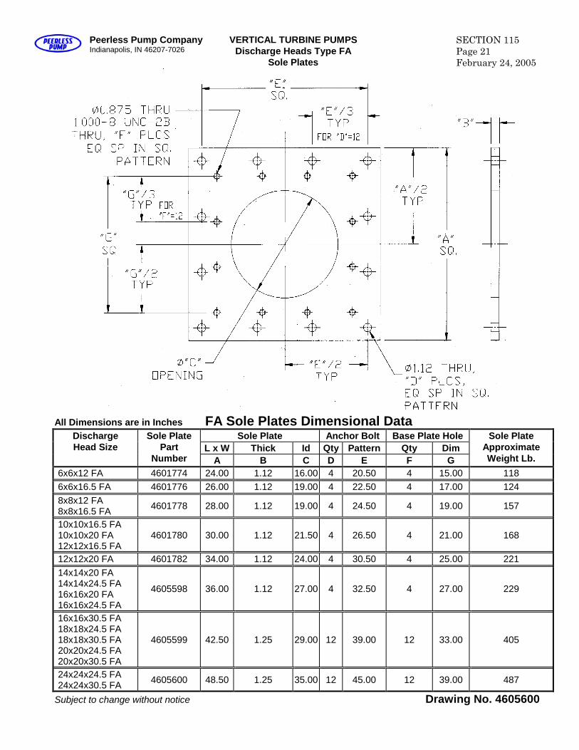
VERTICAL TURBINE PUMPSDischarge Heads Type FA
Sole Plates
SECTION 115Page 21February 24, 2005
All Dimensions are in Inches FA Sole Plates Dimensional DataSole Plate Anchor Bolt Base Plate Hole
L x W Thick Id Qty Pattern Qty DimDischargeHead Size
Sole PlatePart
Number A B C D E F G
Sole PlateApproximateWeight Lb.
6x6x12 FA 4601774 24.00 1.12 16.00 4 20.50 4 15.00 1186x6x16.5 FA 4601776 26.00 1.12 19.00 4 22.50 4 17.00 1248x8x12 FA8x8x16.5 FA 4601778 28.00 1.12 19.00 4 24.50 4 19.00 157
10x10x16.5 FA10x10x20 FA12x12x16.5 FA
4601780 30.00 1.12 21.50 4 26.50 4 21.00 168
12x12x20 FA 4601782 34.00 1.12 24.00 4 30.50 4 25.00 22114x14x20 FA14x14x24.5 FA16x16x20 FA16x16x24.5 FA
4605598 36.00 1.12 27.00 4 32.50 4 27.00 229
16x16x30.5 FA18x18x24.5 FA18x18x30.5 FA20x20x24.5 FA20x20x30.5 FA
4605599 42.50 1.25 29.00 12 39.00 12 33.00 405
24x24x24.5 FA24x24x30.5 FA 4605600 48.50 1.25 35.00 12 45.00 12 39.00 487
Subject to change without notice Drawing No. 4605600
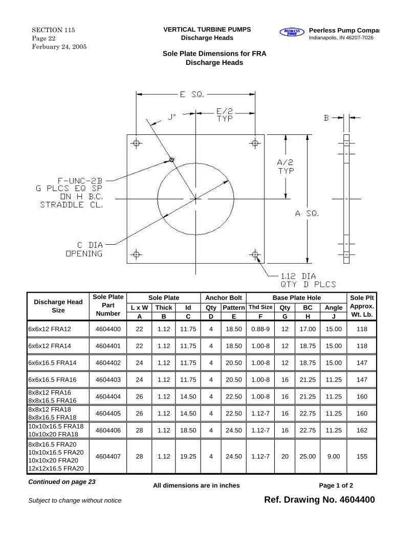
L x W Thick Id Qty Pattern Thd Size Qty BC AngleA B C D E F G H J
6x6x12 FRA12 4604400 22 1.12 11.75 4 18.50 0.88-9 12 17.00 15.00 118
6x6x12 FRA14 4604401 22 1.12 11.75 4 18.50 1.00-8 12 18.75 15.00 118
6x6x16.5 FRA14 4604402 24 1.12 11.75 4 20.50 1.00-8 12 18.75 15.00 147
6x6x16.5 FRA16 4604403 24 1.12 11.75 4 20.50 1.00-8 16 21.25 11.25 147
8x8x12 FRA168x8x16.5 FRA16
4604404 26 1.12 14.50 4 22.50 1.00-8 16 21.25 11.25 160
8x8x12 FRA188x8x16.5 FRA18
4604405 26 1.12 14.50 4 22.50 1.12-7 16 22.75 11.25 160
10x10x16.5 FRA1810x10x20 FRA18
4604406 28 1.12 18.50 4 24.50 1.12-7 16 22.75 11.25 162
8x8x16.5 FRA2010x10x16.5 FRA2010x10x20 FRA2012x12x16.5 FRA20
4604407 28 1.12 19.25 4 24.50 1.12-7 20 25.00 9.00 155
All dimensions are in inches
Subject to change without notice Ref. Drawing No. 4604400
Page 1 of 2Continued on page 23
Discharge HeadSize
Sole PlatePart
Number
Base Plate Hole Sole PltApprox.Wt. Lb.
Sole Plate Anchor Bolt
VERTICAL TURBINE PUMPSDischarge Heads
SECTION 115Page 22Ferbuary 24, 2005
Peerless Pump CompanyIndianapolis, IN 46207-7026
Sole Plate Dimensions for FRADischarge Heads
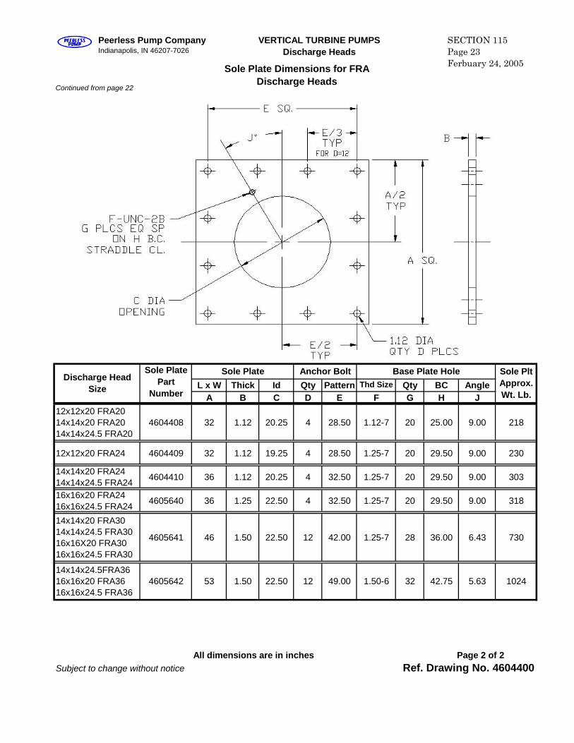
Continued from page 22
L x W Thick Id Qty Pattern Thd Size Qty BC AngleA B C D E F G H J
12x12x20 FRA2014x14x20 FRA2014x14x24.5 FRA20
4604408 32 1.12 20.25 4 28.50 1.12-7 20 25.00 9.00 218
12x12x20 FRA24 4604409 32 1.12 19.25 4 28.50 1.25-7 20 29.50 9.00 230
14x14x20 FRA2414x14x24.5 FRA24
4604410 36 1.12 20.25 4 32.50 1.25-7 20 29.50 9.00 303
16x16x20 FRA2416x16x24.5 FRA24
4605640 36 1.25 22.50 4 32.50 1.25-7 20 29.50 9.00 318
14x14x20 FRA3014x14x24.5 FRA3016x16X20 FRA3016x16x24.5 FRA30
4605641 46 1.50 22.50 12 42.00 1.25-7 28 36.00 6.43 730
14x14x24.5FRA3616x16x20 FRA3616x16x24.5 FRA36
4605642 53 1.50 22.50 12 49.00 1.50-6 32 42.75 5.63 1024
All dimensions are in inchesSubject to change without notice Ref. Drawing No. 4604400
Page 2 of 2
Discharge HeadSize
Sole PlatePart
Number
Base Plate Hole Sole PltApprox.Wt. Lb.
Sole Plate Anchor Bolt
VERTICAL TURBINE PUMPSDischarge Heads
SECTION 115Page 23Ferbuary 24, 2005
Peerless Pump CompanyIndianapolis, IN 46207-7026
Sole Plate Dimensions for FRADischarge Heads
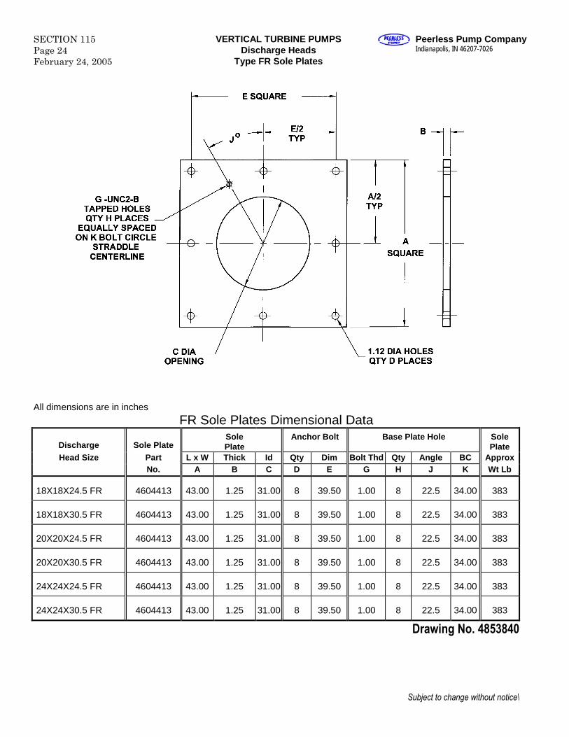
SECTION 115Page 24February 24, 2005
VERTICAL TURBINE PUMPSDischarge Heads
Type FR Sole Plates
Peerless Pump CompanyIndianapolis, IN 46207-7026
All dimensions are in inches
FR Sole Plates Dimensional Data
Discharge Sole PlateSolePlate
Anchor Bolt Base Plate Hole SolePlate
Head Size Part L x W Thick Id Qty Dim Bolt Thd Qty Angle BC ApproxNo. A B C D E G H J K Wt Lb
18X18X24.5 FR 4604413 43.00 1.25 31.00 8 39.50 1.00 8 22.5 34.00 383
18X18X30.5 FR 4604413 43.00 1.25 31.00 8 39.50 1.00 8 22.5 34.00 383
20X20X24.5 FR 4604413 43.00 1.25 31.00 8 39.50 1.00 8 22.5 34.00 383
20X20X30.5 FR 4604413 43.00 1.25 31.00 8 39.50 1.00 8 22.5 34.00 383
24X24X24.5 FR 4604413 43.00 1.25 31.00 8 39.50 1.00 8 22.5 34.00 383
24X24X30.5 FR 4604413 43.00 1.25 31.00 8 39.50 1.00 8 22.5 34.00 383
Drawing No. 4853840
Subject to change without notice\
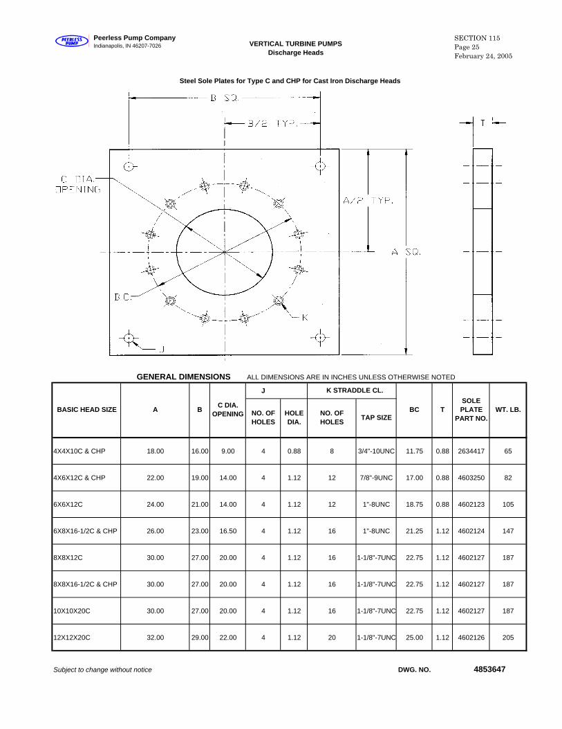
GENERAL DIMENSIONS ALL DIMENSIONS ARE IN INCHES UNLESS OTHERWISE NOTED
J
4X4X10C & CHP 18.00 16.00 9.00 4 0.88 8 3/4"-10UNC 11.75 0.88 2634417 65
4X6X12C & CHP 22.00 19.00 14.00 4 1.12 12 7/8"-9UNC 17.00 0.88 4603250 82
6X6X12C 24.00 21.00 14.00 4 1.12 12 1"-8UNC 18.75 0.88 4602123 105
6X8X16-1/2C & CHP 26.00 23.00 16.50 4 1.12 16 1"-8UNC 21.25 1.12 4602124 147
8X8X12C 30.00 27.00 20.00 4 1.12 16 1-1/8"-7UNC 22.75 1.12 4602127 187
8X8X16-1/2C & CHP 30.00 27.00 20.00 4 1.12 16 1-1/8"-7UNC 22.75 1.12 4602127 187
10X10X20C 30.00 27.00 20.00 4 1.12 16 1-1/8"-7UNC 22.75 1.12 4602127 187
12X12X20C 32.00 29.00 22.00 4 1.12 20 1-1/8"-7UNC 25.00 1.12 4602126 205
Subject to change without notice DWG. NO. 4853647
A B C DIA. OPENING TAP SIZE
BASIC HEAD SIZE
Steel Sole Plates for Type C and CHP for Cast Iron Discharge Heads
K STRADDLE CL.
BC TSOLE PLATE
PART NO.WT. LB.NO. OF
HOLESHOLE DIA.
NO. OF HOLES
VERTICAL TURBINE PUMPSDischarge Heads
Peerless Pump CompanyIndianapolis, IN 46207-7026
SECTION 115Page 25February 24, 2005
SECTION 115Page 26February 24, 2005
VERTICAL TURBINE PUMPSSteel Sole Plates for Type UGUnder grade Discharge Heads
Peerless Pump CompanyIndianapolis, IN 46207-7026
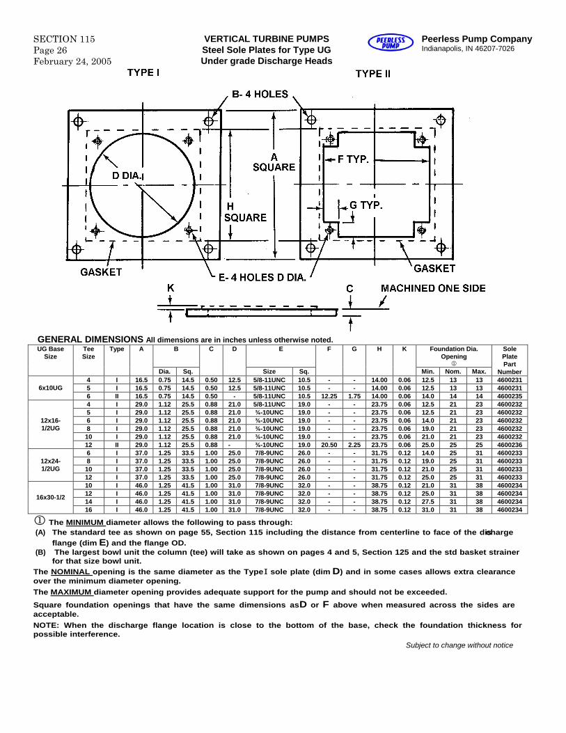
GENERAL DIMENSIONS All dimensions are in inches unless otherwise noted.B E Foundation Dia.
Opening
UG BaseSize
TeeSize
Type A
Dia. Sq.
C D
Size Sq.
F G H K
Min. Nom. Max.
SolePlatePart
Number4 I 16.5 0.75 14.5 0.50 12.5 5/8-11UNC 10.5 - - 14.00 0.06 12.5 13 13 46002315 I 16.5 0.75 14.5 0.50 12.5 5/8-11UNC 10.5 - - 14.00 0.06 12.5 13 13 46002316x10UG6 II 16.5 0.75 14.5 0.50 - 5/8-11UNC 10.5 12.25 1.75 14.00 0.06 14.0 14 14 46002354 I 29.0 1.12 25.5 0.88 21.0 5/8-11UNC 19.0 - - 23.75 0.06 12.5 21 23 46002325 I 29.0 1.12 25.5 0.88 21.0 ¾-10UNC 19.0 - - 23.75 0.06 12.5 21 23 46002326 I 29.0 1.12 25.5 0.88 21.0 ¾-10UNC 19.0 - - 23.75 0.06 14.0 21 23 46002328 I 29.0 1.12 25.5 0.88 21.0 ¾-10UNC 19.0 - - 23.75 0.06 19.0 21 23 460023210 I 29.0 1.12 25.5 0.88 21.0 ¾-10UNC 19.0 - - 23.75 0.06 21.0 21 23 4600232
12x16-1/2UG
12 II 29.0 1.12 25.5 0.88 - ¾-10UNC 19.0 20.50 2.25 23.75 0.06 25.0 25 25 46002366 I 37.0 1.25 33.5 1.00 25.0 7/8-9UNC 26.0 - - 31.75 0.12 14.0 25 31 46002338 I 37.0 1.25 33.5 1.00 25.0 7/8-9UNC 26.0 - - 31.75 0.12 19.0 25 31 460023310 I 37.0 1.25 33.5 1.00 25.0 7/8-9UNC 26.0 - - 31.75 0.12 21.0 25 31 4600233
12x24-1/2UG
12 I 37.0 1.25 33.5 1.00 25.0 7/8-9UNC 26.0 - - 31.75 0.12 25.0 25 31 460023310 I 46.0 1.25 41.5 1.00 31.0 7/8-9UNC 32.0 - - 38.75 0.12 21.0 31 38 460023412 I 46.0 1.25 41.5 1.00 31.0 7/8-9UNC 32.0 - - 38.75 0.12 25.0 31 38 460023414 I 46.0 1.25 41.5 1.00 31.0 7/8-9UNC 32.0 - - 38.75 0.12 27.5 31 38 4600234
16x30-1/2
16 I 46.0 1.25 41.5 1.00 31.0 7/8-9UNC 32.0 - - 38.75 0.12 31.0 31 38 4600234
The MINIMUM diameter allows the following to pass through:(A) The standard tee as shown on page 55, Section 115 including the distance from centerline to face of the discharge
flange (dim E) and the flange OD.(B) The largest bowl unit the column (tee) will take as shown on pages 4 and 5, Section 125 and the std basket strainer
for that size bowl unit.The NOMINAL opening is the same diameter as the TypeI sole plate (dim D) and in some cases allows extra clearanceover the minimum diameter opening.The MAXIMUM diameter opening provides adequate support for the pump and should not be exceeded.
Square foundation openings that have the same dimensions asD or F above when measured across the sides areacceptable.NOTE: When the discharge flange location is close to the bottom of the base, check the foundation thickness forpossible interference.
Subject to change without notice
Peerless Pump CompanyIndianapolis, IN 46207-7026
VERTICAL TURBINE PUMPS SECTION 115Page 27February 24, 2005
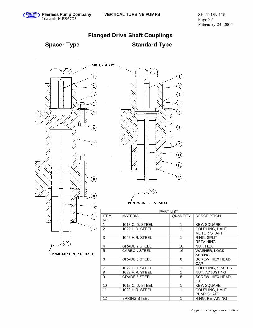
Flanged Drive Shaft Couplings
Subject to change without notice
Standard TypeSpacer Type
PART LISTITEMNO.
MATERIAL QUANTITY DESCRIPTION
1 1018 C. D. STEEL 1 KEY, SQUARE2 1022 H.R. STEEL 1 COUPLING, HALF
MOTOR SHAFT3 1045 H.R. STEEL 1 RING, SPLIT
RETAINING4 GRADE 2 STEEL 16 NUT, HEX5 CARBON STEEL 16 WASHER, LOCK
SPRING6 GRADE 5 STEEL 8 SCREW, HEX HEAD
CAP7 1022 H.R. STEEL 1 COUPLING, SPACER8 1022 H.R. STEEL 1 NUT, ADJUSTING9 GRADE 5 STEEL 8 SCREW, HEX HEAD
CAP10 1018 C. D. STEEL 1 KEY, SQUARE11 1022 H.R. STEEL 1 COUPLING, HALF
PUMP SHAFT12 SPRING STEEL 1 RING, RETAINING

Discharge Head Size Stuffing Box Register Type Shaft or
Sleeve SizeQuantity
Rings Size Square
2.5x2.5x10S 0.75 0.382.5x3x10S 1.00 0.254x4x10C 0.756x10UG 1.006x6x12G 1.196x6x12F8x8x12F12x16.5UG VI 0.75 5
1.001.191.501.691.94
6x6x16.5F8x8x16.5G8x8x16.5F10x10x16.5F10x10x20F10x10x20G12x12x16.5F12x12x20F12x12x20G12x24.5UG14x14x20F14x14x24.5F14x14x24.5S16x16x20F16x16x24.5F18x18x24.5F20x20x24.5F24x24x24.5F16x16x30.5S16x30.5UG
1.942.192.44
16x16x30.5F18x18x30.5F20x20x30.5F 2.94 7 0.6224x24x30.5F 3.19 7 0.75
"F" designates standard FA or FRA type fabricated head
Subject to change without notice
0.50
5
5
6
6
0.501.50 5
0.38
0.38II
VI
1.69
II
2.19
2.44
1.19
1.50
1.69
1.94
Integrally Cast -
6.38
5.56
4.69
3.88
VI
VI
III or IV
II
8.50 VI2.69
0.50
0.62
8 0.62
8
0.38
0.50
0.62
1.00
5
6
VERTICAL TURBINE PUMPSDischarge Heads
SECTION 115Page 28February 24, 2005
Peerless Pump CompanyIndianapolis, IN 46207-7026
Stuffing Box Data
ALL DIMENSIONS ARE IN INCHES UNLESS OTHERWISE NOTED
Peerless Pump CompanyIndianapolis, IN 46207-7026
VERTICAL TURBINE PUMPSDischarge Head Stuffing Boxes
SECTION 115Page 29February 24, 2005
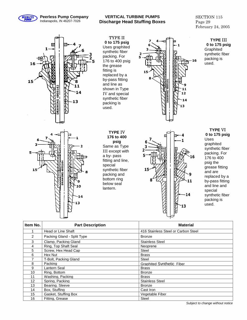
Item No. Part Description Material1 Head or Line Shaft 416 Stainless Steel or Carbon Steel2 Packing Gland - Split Type Bronze3 Clamp, Packing Gland Stainless Steel4 Ring, Top Shaft Seal Neoprene5 Screw, Hex Head Cap Steel6 Hex Nut Brass7 T-Bolt, Packing Gland Steel8 Packing Graphited Synthetic Fiber9 Lantern Seal Brass
10 Ring, Bottom Bronze11 Washing, Packing Brass12 Spring, Packing Stainless Steel13 Bearing. Sleeve Bronze14 Box, Stuffing Cast Iron15 Gasket, Stuffing Box Vegetable Fiber16 Fitting, Grease Steel
Subject to change without notice
TYPE II0 to 175 psig
Uses graphitedsynthetic fiberpacking. For176 to 400 psigthe greasefitting isreplaced by aby-pass fittingand line asshown in TypeIV and specialsynthetic fiberpacking isused.
TYPE III0 to 175 psig
Graphitedsynthetic fiberpacking isused.
TYPE VI0 to 175 psigUsesgraphitedsynthetic fiberpacking. For176 to 400psig thegrease fittingand arereplaced by aby-pass fittingand line andspecialsynthetic fiberpacking isused.
TYPE IV176 to 400
psigSame as TypeIII except witha by- passfitting and line,specialsynthetic fiberpacking andbottom ringbelow seallantern.
SECTION 115Page 30February 28, 2005
VERTICAL TURBINE PUMPSTube Tension Nuts
Peerless Pump CompanyIndianapolis, IN 46207-7026
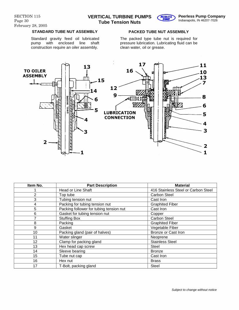
Item No. Part Description Material1 Head or Line Shaft 416 Stainless Steel or Carbon Steel2 Top tube Carbon Steel3 Tubing tension nut Cast Iron4 Packing for tubing tension nut Graphited Fiber5 Packing follower for tubing tension nut Cast Iron6 Gasket for tubing tension nut Copper7 Stuffing Box Carbon Steel8 Packing Graphited Fiber9 Gasket Vegetable Fiber10 Packing gland (pair of halves) Bronze or Cast Iron11 Water slinger Neoprene12 Clamp for packing gland Stainless Steel13 Hex head cap screw Steel14 Sleeve bearing Bronze15 Tube nut cap Cast Iron16 Hex nut Brass17 T-Bolt, packing gland Steel
Subject to change without notice
STANDARD TUBE NUT ASSEMBLY
Standard gravity feed oil lubricatedpump with enclosed line shaftconstruction require an oiler assembly.
The packed type tube nut is required forpressure lubrication. Lubricating fluid can beclean water, oil or grease.
PACKED TUBE NUT ASSEMBLY
Subject to change without notice
Peerless Pump CompanyIndianapolis, IN 46207-7026
VERTICAL TURBINE PUMPSDischarge Heads
SECTION 115Page 31February 24, 2005
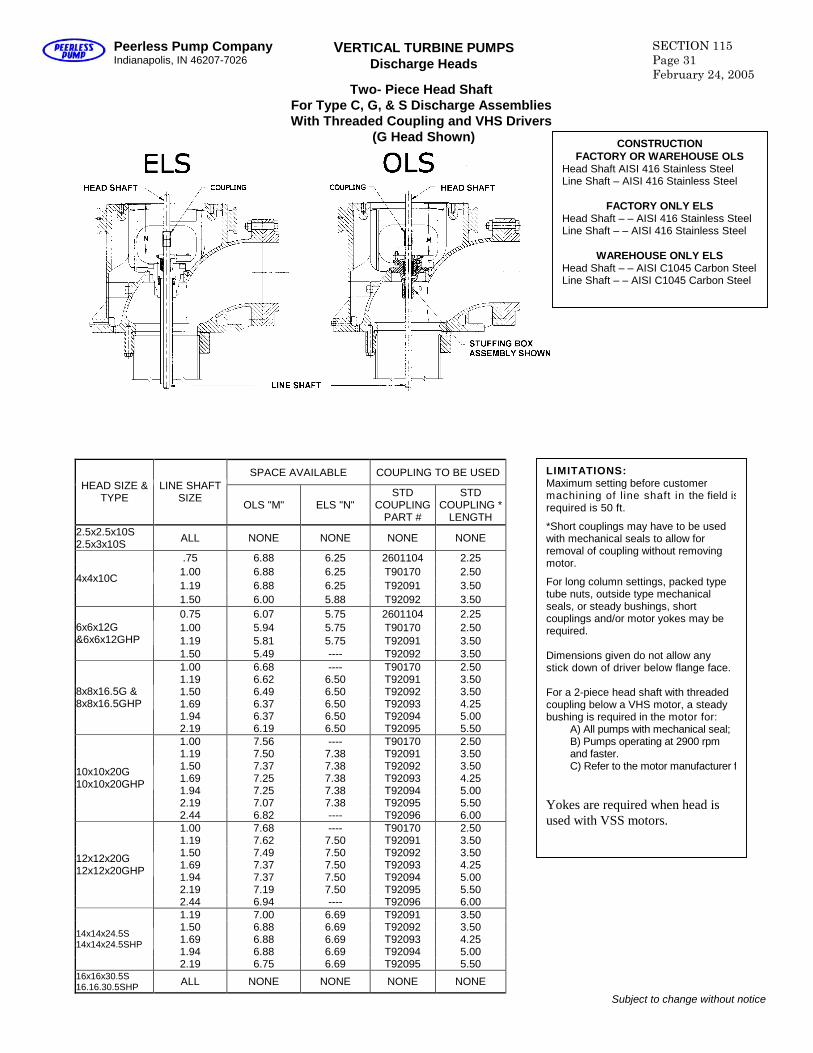
Two- Piece Head ShaftFor Type C, G, & S Discharge AssembliesWith Threaded Coupling and VHS Drivers
(G Head Shown)
SPACE AVAILABLE COUPLING TO BE USEDHEAD SIZE &
TYPELINE SHAFT
SIZEOLS "M" ELS "N"
STDCOUPLING
PART #
STDCOUPLING *
LENGTH2.5x2.5x10S2.5x3x10S ALL NONE NONE NONE NONE
.75 6.88 6.25 2601104 2.251.00 6.88 6.25 T90170 2.501.19 6.88 6.25 T92091 3.50
4x4x10C
1.50 6.00 5.88 T92092 3.500.75 6.07 5.75 2601104 2.251.00 5.94 5.75 T90170 2.501.19 5.81 5.75 T92091 3.50
6x6x12G&6x6x12GHP
1.50 5.49 ---- T92092 3.501.00 6.68 ---- T90170 2.501.19 6.62 6.50 T92091 3.501.50 6.49 6.50 T92092 3.501.69 6.37 6.50 T92093 4.251.94 6.37 6.50 T92094 5.00
8x8x16.5G &8x8x16.5GHP
2.19 6.19 6.50 T92095 5.501.00 7.56 ---- T90170 2.501.19 7.50 7.38 T92091 3.501.50 7.37 7.38 T92092 3.501.69 7.25 7.38 T92093 4.251.94 7.25 7.38 T92094 5.002.19 7.07 7.38 T92095 5.50
10x10x20G10x10x20GHP
2.44 6.82 ---- T92096 6.001.00 7.68 ---- T90170 2.501.19 7.62 7.50 T92091 3.501.50 7.49 7.50 T92092 3.501.69 7.37 7.50 T92093 4.251.94 7.37 7.50 T92094 5.002.19 7.19 7.50 T92095 5.50
12x12x20G12x12x20GHP
2.44 6.94 ---- T92096 6.001.19 7.00 6.69 T92091 3.501.50 6.88 6.69 T92092 3.501.69 6.88 6.69 T92093 4.251.94 6.88 6.69 T92094 5.00
14x14x24.5S14x14x24.5SHP
2.19 6.75 6.69 T92095 5.5016x16x30.5S16.16.30.5SHP ALL NONE NONE NONE NONE
CONSTRUCTIONFACTORY OR WAREHOUSE OLS
Head Shaft AISI 416 Stainless SteelLine Shaft –AISI 416 Stainless Steel
FACTORY ONLY ELSHead Shaft ––AISI 416 Stainless SteelLine Shaft ––AISI 416 Stainless Steel
WAREHOUSE ONLY ELSHead Shaft ––AISI C1045 Carbon SteelLine Shaft ––AISI C1045 Carbon Steel
LIMITATIONS:Maximum setting before customermachining of line shaft in the field isrequired is 50 ft.
*Short couplings may have to be usedwith mechanical seals to allow forremoval of coupling without removingmotor.
For long column settings, packed typetube nuts, outside type mechanicalseals, or steady bushings, shortcouplings and/or motor yokes may berequired.
Dimensions given do not allow anystick down of driver below flange face.
For a 2-piece head shaft with threadedcoupling below a VHS motor, a steadybushing is required in the motor for:
A) All pumps with mechanical seal;B) Pumps operating at 2900 rpmand faster.C) Refer to the motor manufacturer for
Yokes are required when head isused with VSS motors.
SECTION 115Page 32February 24, 2005
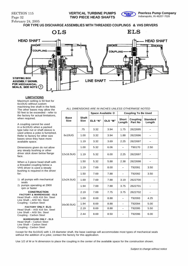
VERTICAL TURBINE PUMPSTWO PIECE HEAD SHAFTS
Peerless Pump CompanyIndianapolis, IN 46207-7026
FOR TYPE UG DISCHARGE ASSEMBLIES WITH THREADED COUPLINGS & VHS DRIVERS
CONSTRUCTIONFACTORY & WAREHOUSE - OLS
Head Shaft –AISI 416 Stn. SteelLine Shaft –AISI Stn. SteelCoupling - Carbon Steel
FACTORY ONLY- ELS-Head Shaft –AISI 416 Stn. SteelLine Shaft –AISI Stn. SteelCoupling - Carbon Steel
WAREHOUSE ONLY - ELSHead Shaft –Carbon SteelLine Shaft –Carbon SteelCoupling - Carbon Steel
Maximum setting is 50 feet for6x10UG without custommachining line shaft in the field.The other bases may allow the50 feet to be exceeded - refer tothe factory for actual limitations,when required.
A coupling cannot be usedin a 6x10UG when a packedtype tube nut or shaft sleeve isused unless a yoke is furnished.Refer to factory for other sizebases since they have moreavailable space.
Dimensions given do not allowany steady bushing or otherdriver stick down below flangeface.
When a 2-piece head shaft witha threaded coupling below aVHS driver is used a steadybushing is required in the driverfor:
1) all pumps with mechanicalseals
2) pumps operating at 2900rpm or faster
Space Available Coupling To Be Used
BaseSize
ShaftSize ELS “N” OLS “M” Short
LengthCouplingPart No
StandardLength
.75 3.32 3.94 1.75 2622695 -
1.00 3.32 3.94 1.88 2622696 -6x10UG
1.19 3.32 3.69 2.25 2622697 -
1.00 5.32 6.06 - T90170 2.50
1.19 5.32 6.00 2.25 2622697 -12x16.5UG
1.50 5.32 5.88 2.38 2622698 -
1.19 7.69 8.00 - T92091 3.50
1.50 7.69 7.88 - T92092 3.50
1.69 7.69 7.88 3.19 2622700 -
1.94 7.69 7.88 3.75 2622701 -
12x24.5UG
2.19 7.69 7.75 3.75 2622702 -
1.69 8.69 8.88 - T92093 4.25
1.94 8.69 8.88 - T92094 5.00
2.19 8.69 8.88 - T92095 5.5016x30.5UG
2.44 8.69 8.50 - T92096 6.00
ALL DIMENSIONS ARE IN INCHES UNLESS OTHERWISE NOTED
LIMITATIONS
Except for the 6x10UG with 1.19 diameter shaft, the base castings will accommodate most types of mechanical sealswithout the addition of a yoke; contact the factory for this application.
Use 1/2 of M or N dimension to place the coupling in the center of the available space for the construction shown.
Subject to change without notice
Peerless Pump CompanyIndianapolis, IN 46207-7026
VERTICAL TURBINE PUMPS SECTION 115Page 33February 24, 2005
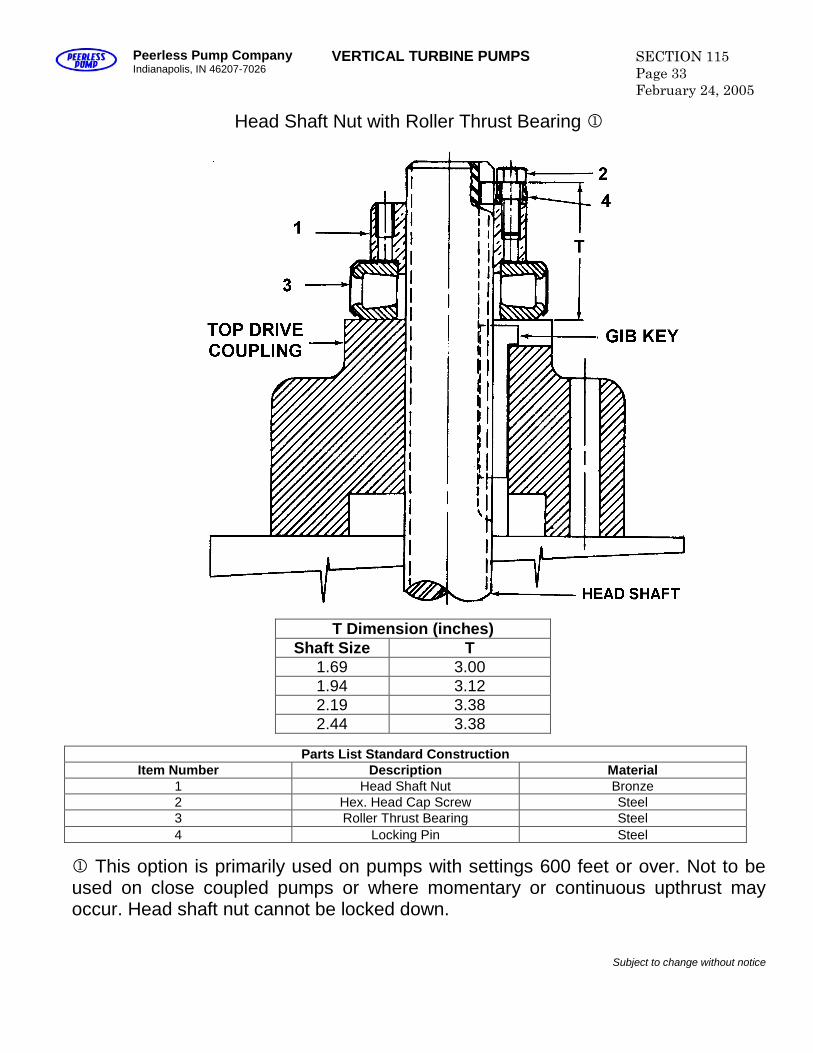
Head Shaft Nut with Roller Thrust Bearing
T Dimension (inches)Shaft Size T
1.69 3.001.94 3.122.19 3.382.44 3.38
Parts List Standard ConstructionItem Number Description Material
1 Head Shaft Nut Bronze2 Hex. Head Cap Screw Steel3 Roller Thrust Bearing Steel4 Locking Pin Steel
This option is primarily used on pumps with settings 600 feet or over. Not to beused on close coupled pumps or where momentary or continuous upthrust mayoccur. Head shaft nut cannot be locked down.
Subject to change without notice
SECTION 115Page 34February 24, 2005
VERTICAL TURBINE PUMPSPre-lubrication Methods
for Open Line shaft Column
Peerless Pump CompanyIndianapolis, IN 46207-7026
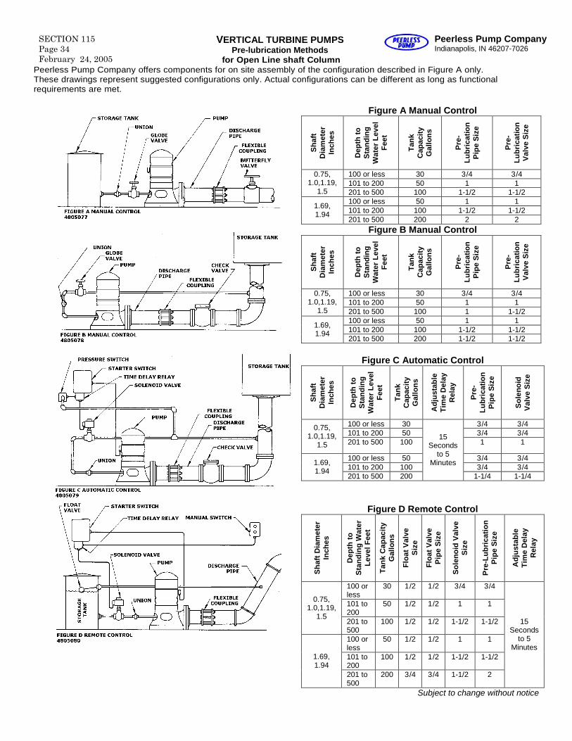
Peerless Pump Company offers components for on site assembly of the configuration described in Figure A only.These drawings represent suggested configurations only. Actual configurations can be different as long as functionalrequirements are met.
Figure A Manual Control
Sh
aft
Dia
met
erIn
ches
Dep
thto
Sta
nd
ing
Wat
erL
evel
Fee
t
Tan
kC
apac
ity
Gal
lon
s
Pre
-L
ub
rica
tion
Pip
eS
ize
Pre
-L
ub
rica
tion
Val
veS
ize
100 or less 30 3/4 3/4101 to 200 50 1 1
0.75,1.0,1.19,
1.5 201 to 500 100 1-1/2 1-1/2100 or less 50 1 1101 to 200 100 1-1/2 1-1/2
1.69,1.94
201 to 500 200 2 2Figure B Manual Control
Sh
aft
Dia
met
erIn
ches
Dep
thto
Sta
nd
ing
Wat
erL
evel
Fee
t
Tan
kC
apac
ity
Gal
lon
s
Pre
-L
ub
rica
tion
Pip
eS
ize
Pre
-L
ub
rica
tion
Val
veS
ize
100 or less 30 3/4 3/4101 to 200 50 1 1
0.75,1.0,1.19,
1.5 201 to 500 100 1 1-1/2100 or less 50 1 1101 to 200 100 1-1/2 1-1/2
1.69,1.94
201 to 500 200 1-1/2 1-1/2
Figure C Automatic Control
Sh
aft
Dia
met
erIn
ches
Dep
thto
Sta
nd
ing
Wat
erL
evel
Fee
t
Tan
kC
apac
ity
Gal
lon
s
Ad
just
able
Tim
eD
elay
Rel
ay
Pre
-L
ub
rica
tion
Pip
eS
ize
So
leno
idV
alve
Siz
e
100 or less 30 3/4 3/4101 to 200 50 3/4 3/4
0.75,1.0,1.19,
1.5 201 to 500 100 1 1
100 or less 50 3/4 3/4101 to 200 100 3/4 3/4
1.69,1.94
201 to 500 200
15Seconds
to 5Minutes
1-1/4 1-1/4
Figure D Remote Control
Sh
aft
Dia
met
erIn
ches
Dep
thto
Sta
nd
ing
Wat
erL
evel
Fee
t
Tan
kC
apac
ity
Gal
lon
s
Flo
atV
alve
Siz
e
Flo
atV
alve
Pip
eS
ize
So
leno
idV
alve
Siz
e
Pre
-Lu
bri
cati
on
Pip
eS
ize
Ad
just
able
Tim
eD
elay
Rel
ay
100 orless
30 1/2 1/2 3/4 3/4
101 to200
50 1/2 1/2 1 10.75,1.0,1.19,
1.5201 to500
100 1/2 1/2 1-1/2 1-1/2
100 orless
50 1/2 1/2 1 1
101 to200
100 1/2 1/2 1-1/2 1-1/21.69,1.94
201 to500
200 3/4 3/4 1-1/2 2
15Seconds
to 5Minutes
Subject to change without notice
Peerless Pump CompanyIndianapolis, IN 46207-7026
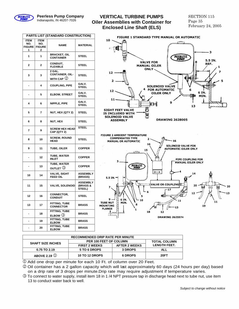
VERTICAL TURBINE PUMPSOiler Assemblies with Container for
Enclosed Line Shaft (ELS)
SECTION 115Page 35February 24, 2005
PARTS LIST (STANDARD CONSTRUCTION)ITEMNO.
FIGURE1
ITEMNO.
FIGURE2
NAME MATERIAL
1 1 BRACKET, OILCONTAINER STEEL
2 2 CONDUIT,FLEXIBLE STEEL
3 32 GAL.CONTAINER, OIL-
WITH CAPSTEEL
- 4 COUPLING, PIPE GALV.STEEL
- 5 ELBOW, STREET GALV.STEEL
4 6 NIPPLE, PIPE GALV.STEEL
5 7 NUT, HEX (QTY 2) STEEL
6 8 NUT, HEX STEEL
7 9 SCREW HEX HEADCAP (QTY 2)
STEEL
8 10 SCREW, ROUNDHEAD STEEL
9 11 TUBE, OILER COPPER
- 12 TUBE, WATERINLET COPPER
- 13TUBE, WATER
OUTLET COPPER
10 14 VALVE, SIGHTFEED OIL
ASSEMBLY(BRASS)
11 15 VALVE, SOLENOIDASSEMBLY(BRASS &STEEL)
12 16 CONNECTOR,CONDUIT STEEL
13 17 FITTING, TUBECONNECTOR BRASS
- 18FITTING, TUBE
ELBOW BRASS
- 19 FITTING, TUBEELBOW BRASS
- 20 FITTING, TUBEELBOW BRASS
RECOMMENDED DRIP RATE PER MINUTEPER 100 FEET OF COLUMN
SHAFT SIZE INCHESFIRST 2 WEEKS AFTER 2 WEEKS
TOTAL COLUMNLENGTH FEET.
0.75 TO 2.19 5 TO 6 DROPS 3 DROPS ALL
ABOVE 2.19 10 TO 12 DROPS 6 DROPS 20FT
Add one drop per minute for each 10 Ft. of column over 20 Feet.Oil container has a 2 gallon capacity which will last approximately 60 days (24 hours per day) based
on a drip rate of 3 drops per minute.Drip rate may require adjustment if temperature varies.To connect to water supply, install item 18 in 1 /4 NPT pressure tap in discharge head next to tube nut, use item
13 to conduct water back to well.
Subject to change without notice
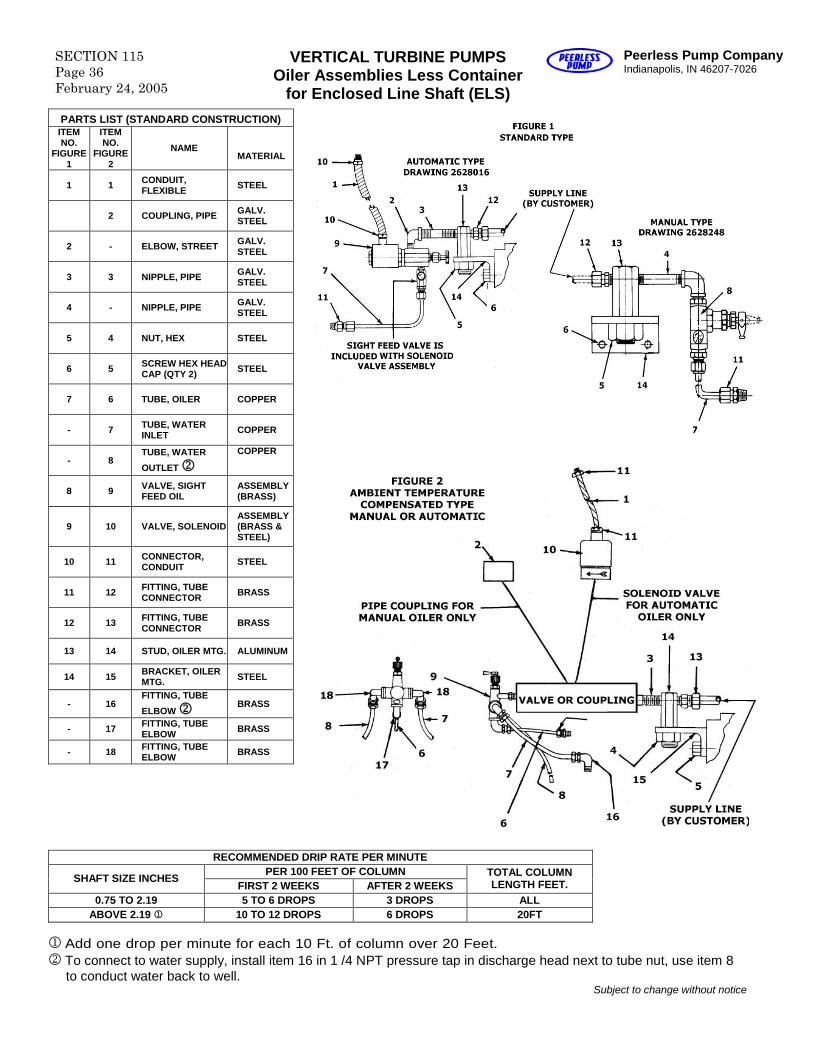
SECTION 115Page 36February 24, 2005
VERTICAL TURBINE PUMPSOiler Assemblies Less Container
for Enclosed Line Shaft (ELS)
Peerless Pump CompanyIndianapolis, IN 46207-7026
PARTS LIST (STANDARD CONSTRUCTION)ITEMNO.
FIGURE1
ITEMNO.
FIGURE2
NAMEMATERIAL
1 1 CONDUIT,FLEXIBLE STEEL
2 COUPLING, PIPE GALV.STEEL
2 - ELBOW, STREET GALV.STEEL
3 3 NIPPLE, PIPE GALV.STEEL
4 - NIPPLE, PIPE GALV.STEEL
5 4 NUT, HEX STEEL
6 5 SCREW HEX HEADCAP (QTY 2) STEEL
7 6 TUBE, OILER COPPER
- 7 TUBE, WATERINLET COPPER
- 8TUBE, WATER
OUTLETCOPPER
8 9 VALVE, SIGHTFEED OIL
ASSEMBLY(BRASS)
9 10 VALVE, SOLENOIDASSEMBLY(BRASS &STEEL)
10 11 CONNECTOR,CONDUIT STEEL
11 12 FITTING, TUBECONNECTOR BRASS
12 13 FITTING, TUBECONNECTOR BRASS
13 14 STUD, OILER MTG. ALUMINUM
14 15 BRACKET, OILERMTG. STEEL
- 16FITTING, TUBE
ELBOW BRASS
- 17 FITTING, TUBEELBOW BRASS
- 18 FITTING, TUBEELBOW BRASS
RECOMMENDED DRIP RATE PER MINUTEPER 100 FEET OF COLUMN
SHAFT SIZE INCHESFIRST 2 WEEKS AFTER 2 WEEKS
TOTAL COLUMNLENGTH FEET.
0.75 TO 2.19 5 TO 6 DROPS 3 DROPS ALLABOVE 2.19 10 TO 12 DROPS 6 DROPS 20FT
Add one drop per minute for each 10 Ft. of column over 20 Feet.To connect to water supply, install item 16 in 1 /4 NPT pressure tap in discharge head next to tube nut, use item 8
to conduct water back to well.Subject to change without notice
Peerless Pump CompanyIndianapolis, IN 46207-7026
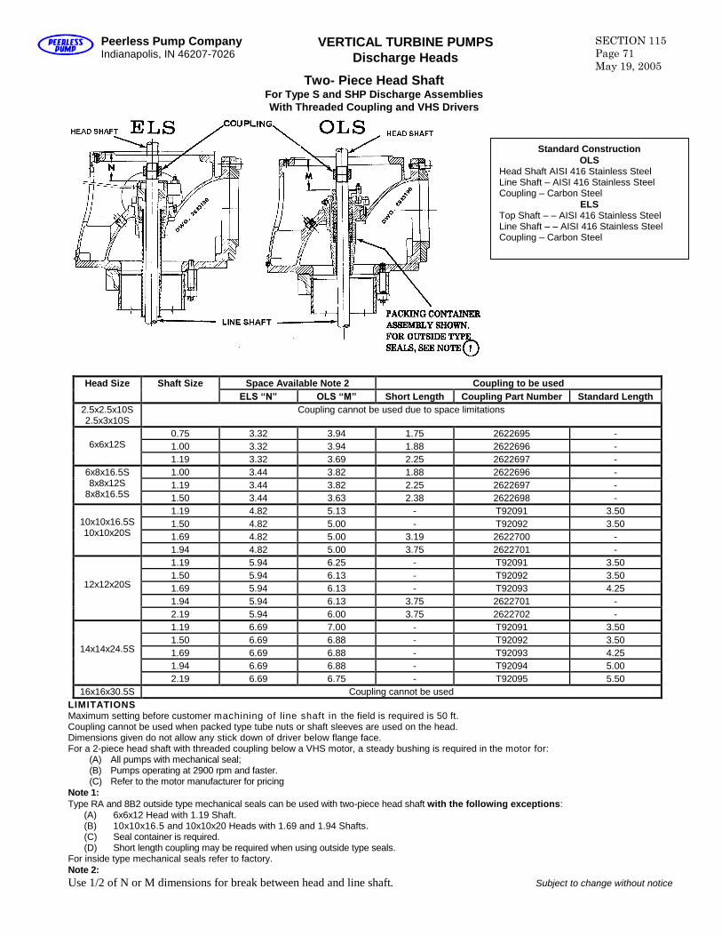
VERTICAL TURBINE PUMPSDischarge Heads
SECTION 115Page 71May 19, 2005
Two- Piece Head ShaftFor Type S and SHP Discharge AssembliesWith Threaded Coupling and VHS Drivers
Space Available Note 2 Coupling to be usedHead Size Shaft SizeELS “N” OLS “M” Short Length Coupling Part Number Standard Length
2.5x2.5x10S2.5x3x10S
Coupling cannot be used due to space limitations
0.75 3.32 3.94 1.75 2622695 -1.00 3.32 3.94 1.88 2622696 -6x6x12S
1.19 3.32 3.69 2.25 2622697 -1.00 3.44 3.82 1.88 2622696 -1.19 3.44 3.82 2.25 2622697 -
6x8x16.5S8x8x12S
8x8x16.5S 1.50 3.44 3.63 2.38 2622698 -1.19 4.82 5.13 - T92091 3.501.50 4.82 5.00 - T92092 3.501.69 4.82 5.00 3.19 2622700 -
10x10x16.5S10x10x20S
1.94 4.82 5.00 3.75 2622701 -1.19 5.94 6.25 - T92091 3.501.50 5.94 6.13 - T92092 3.501.69 5.94 6.13 - T92093 4.251.94 5.94 6.13 3.75 2622701 -
12x12x20S
2.19 5.94 6.00 3.75 2622702 -1.19 6.69 7.00 - T92091 3.501.50 6.69 6.88 - T92092 3.501.69 6.69 6.88 - T92093 4.251.94 6.69 6.88 - T92094 5.00
14x14x24.5S
2.19 6.69 6.75 - T92095 5.5016x16x30.5S Coupling cannot be used
LIMITATIONSMaximum setting before customer machining of line shaft in the field is required is 50 ft.Coupling cannot be used when packed type tube nuts or shaft sleeves are used on the head.Dimensions given do not allow any stick down of driver below flange face.For a 2-piece head shaft with threaded coupling below a VHS motor, a steady bushing is required in the motor for:
(A) All pumps with mechanical seal;(B) Pumps operating at 2900 rpm and faster.(C) Refer to the motor manufacturer for pricing
Note 1:Type RA and 8B2 outside type mechanical seals can be used with two-piece head shaft with the following exceptions:
(A) 6x6x12 Head with 1.19 Shaft.(B) 10x10x16.5 and 10x10x20 Heads with 1.69 and 1.94 Shafts.(C) Seal container is required.(D) Short length coupling may be required when using outside type seals.
For inside type mechanical seals refer to factory.Note 2:Use 1/2 of N or M dimensions for break between head and line shaft. Subject to change without notice
Standard ConstructionOLS
Head Shaft AISI 416 Stainless SteelLine Shaft –AISI 416 Stainless SteelCoupling –Carbon Steel
ELSTop Shaft ––AISI 416 Stainless SteelLine Shaft ––AISI 416 Stainless SteelCoupling –Carbon Steel
SECTION 115Page 72May 19, 2005
VERTICAL TURBINE PUMPSType S Surface Mounted Discharge Heads
Peerless Pump CompanyIndianapolis, IN 46207-7026
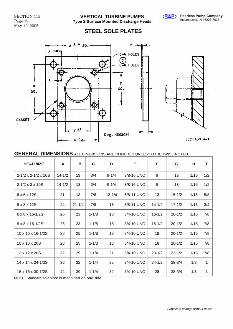
STEEL SOLE PLATES
GENERAL DIMENSIONS ALL DIMENSIONS ARE IN INCHES UNLESS OTHERWISE NOTED
HEAD 8IZE A B C D E F G H T
2-1/2 x 2-1/2 x 10S 14-1/2 13 3/4 9-1/4 3/8-16 UNC 9 13 1/16 1/2
2-1/2 x 3 x 10S 14-1/2 13 3/4 9-1/4 3/8-16 UNC 9 13 1/16 1/2
6 x 6 x 12S 21 18 7/8 13-1/4 5/8-11 UNC 13 15-1/2 1/16 5/8
8 x 8 x 12S 24 21-1/4 7/8 15 5/8-11 UNC 14-1/2 17-1/2 1/16 3/4
6 x 8 x 16-1/2S 26 23 1-1/8 18 3/4-10 UNC 16-1/2 20-1/2 1/16 7/8
8 x 8 x 16-1/2S 26 23 1-1/8 18 3/4-10 UNC 16-1/2 20-1/2 1/16 7/8
10 x 10 x 16-1/2S 28 25 1-1/8 18 3/4-10 UNC 18 20-1/2 1/16 7/8
10 x 10 x 20S 28 25 1-1/8 18 3/4-10 UNC 18 20-1/2 1/16 7/8
12 x 12 x 20S 32 29 1-1/4 21 3/4-10 UNC 20-1/2 23-1/2 1/16 7/8
14 x 14 x 24-1/2S 36 32 1-1/4 25 3/4-10 UNC 24-1/2 28-3/4 1/8 1
16 x 16 x 30-1/2S 42 39 1-1/4 32 3/4-10 UNC 28 38-3/4 1/8 1
NOTE: Standard soleplate is machined on one side.
Subject to change without notice
Subject to change without notice
Peerless Pump CompanyIndianapolis, IN 46207-7026
VERTICAL TURBINE PUMPSCOLUMN
SECTION 120Page 19October 1, 1995
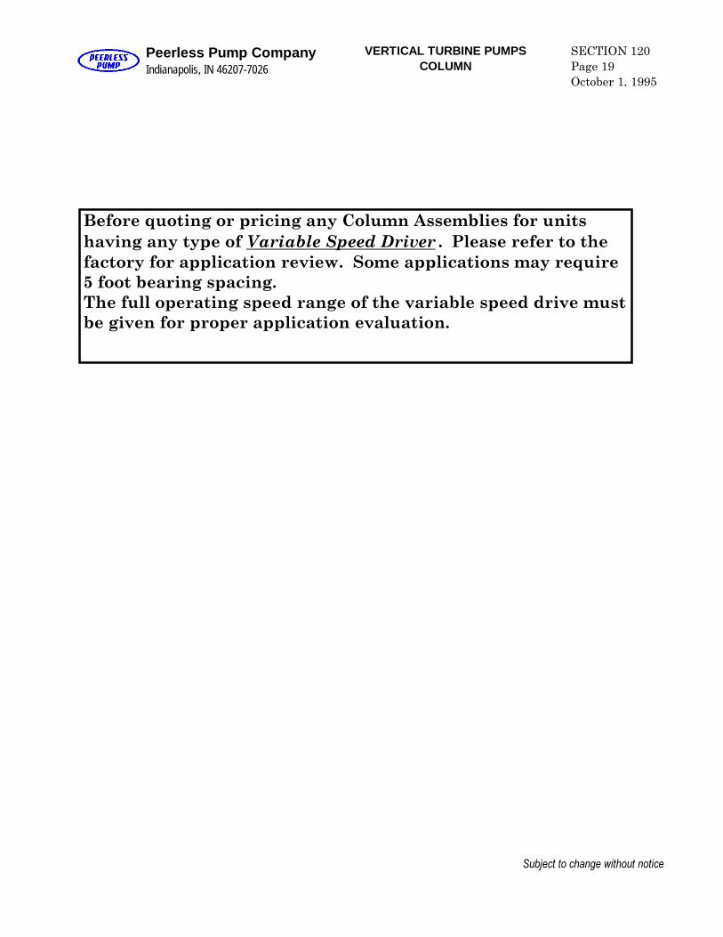
Before quoting or pricing any Column Assemblies for unitshaving any type of Variable Speed Driver . Please refer to thefactory for application review. Some applications may require5 foot bearing spacing.The full operating speed range of the variable speed drive mustbe given for proper application evaluation.
Peerless Pump CompanyIndianapolis, IN 46207-7026
VERTICAL TURBINE PUMPS SECTION 120Page 41June 30, 1980
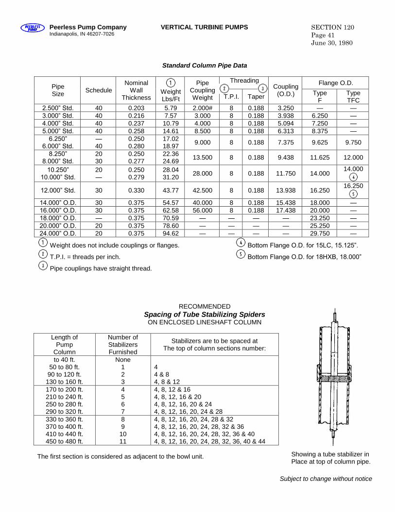
Standard Column Pipe Data
Threading Flange O.D.PipeSize Schedule
NominalWall
ThicknessWeightLbs/Ft
PipeCouplingWeight T.P.I. Taper
Coupling(O.D.) Type
FTypeTFC
2.500” Std. 40 0.203 5.79 2.000# 8 0.188 3.250 — —3.000” Std. 40 0.216 7.57 3.000 8 0.188 3.938 6.250 —4.000” Std. 40 0.237 10.79 4.000 8 0.188 5.094 7.250 —5.000” Std. 40 0.258 14.61 8.500 8 0.188 6.313 8.375 —6.250”
6.000” Std.—40
0.2500.280
17.0218.97 9.000 8 0.188 7.375 9.625 9.750
8.250”8.000” Std.
2030
0.2500.277
22.3624.69 13.500 8 0.188 9.438 11.625 12.000
10.250”10.000” Std.
20—
0.2500.279
28.0431.20 28.000 8 0.188 11.750 14.000
14.000
12.000” Std. 30 0.330 43.77 42.500 8 0.188 13.938 16.25016.250
14.000” O.D. 30 0.375 54.57 40.000 8 0.188 15.438 18.000 —16.000” O.D. 30 0.375 62.58 56.000 8 0.188 17.438 20.000 —18.000” O.D. — 0.375 70.59 — — — — 23.250 —20.000” O.D. 20 0.375 78.60 — — — — 25.250 —24.000” O.D. 20 0.375 94.62 — — — — 29.750 —
Weight does not include couplings or flanges. Bottom Flange O.D. for 15LC, 15.125”.
T.P.I. = threads per inch. Bottom Flange O.D. for 18HXB, 18.000”
Pipe couplings have straight thread.
RECOMMENDEDSpacing of Tube Stabilizing Spiders
ON ENCLOSED LINESHAFT COLUMN
Length ofPump
Column
Number ofStabilizersFurnished
Stabilizers are to be spaced atThe top of column sections number:
to 40 ft.50 to 80 ft.90 to 120 ft.130 to 160 ft.
None123
44 & 84, 8 & 12
170 to 200 ft.210 to 240 ft.250 to 280 ft.290 to 320 ft.
4567
4, 8, 12 & 164, 8, 12, 16 & 204, 8, 12, 16, 20 & 244, 8, 12, 16, 20, 24 & 28
330 to 360 ft.370 to 400 ft.410 to 440 ft.450 to 480 ft.
891011
4, 8, 12, 16, 20, 24, 28 & 324, 8, 12, 16, 20, 24, 28, 32 & 364, 8, 12, 16, 20, 24, 28, 32, 36 & 404, 8, 12, 16, 20, 24, 28, 32, 36, 40 & 44
The first section is considered as adjacent to the bowl unit.
Subject to change without notice
Showing a tube stabilizer inPlace at top of column pipe.
Peerless Pump CompanyIndianapolis, IN 46207-7026
VERTICAL TURBINE PUMPS SECTION 120Page 43June 30, 1980
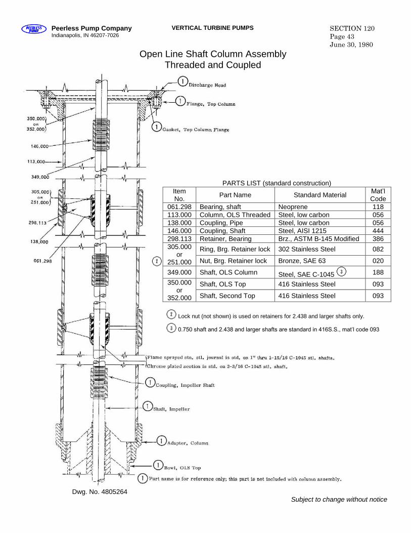
Open Line Shaft Column AssemblyThreaded and Coupled
PARTS LIST (standard construction)ItemNo. Part Name Standard Material Mat’l
Code061.298 Bearing, shaft Neoprene 118113.000 Column, OLS Threaded Steel, low carbon 056138.000 Coupling, Pipe Steel, low carbon 056146.000 Coupling, Shaft Steel, AISI 1215 444298.113 Retainer, Bearing Brz., ASTM B-145 Modified 386
Ring, Brg. Retainer lock 302 Stainless Steel 082305.000or
251.000 Nut, Brg. Retainer lock Bronze, SAE 63 020
349.000 Shaft, OLS Column Steel, SAE C-1045 188
Shaft, OLS Top 416 Stainless Steel 093350.000or
352.000 Shaft, Second Top 416 Stainless Steel 093
Lock nut (not shown) is used on retainers for 2.438 and larger shafts only.
0.750 shaft and 2.438 and larger shafts are standard in 416S.S., mat’l code 093
Dwg. No. 4805264Subject to change without notice
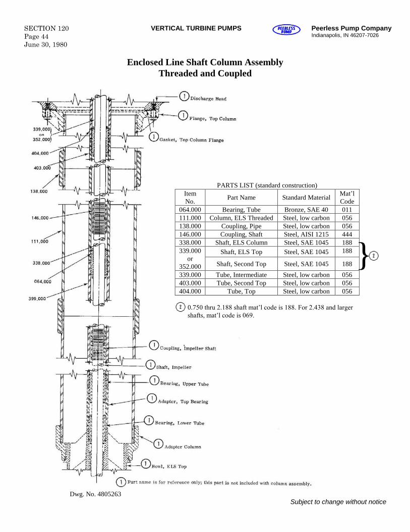
SECTION 120Page 44June 30, 1980
VERTICAL TURBINE PUMPS Peerless Pump CompanyIndianapolis, IN 46207-7026
Enclosed Line Shaft Column AssemblyThreaded and Coupled
PARTS LIST (standard construction)ItemNo. Part Name Standard Material Mat’l
Code064.000 Bearing, Tube Bronze, SAE 40 011111.000 Column, ELS Threaded Steel, low carbon 056138.000 Coupling, Pipe Steel, low carbon 056146.000 Coupling, Shaft Steel, AISI 1215 444338.000 Shaft, ELS Column Steel, SAE 1045 188
Shaft, ELS Top Steel, SAE 1045 188339.000or
352.000 Shaft, Second Top Steel, SAE 1045 188
339.000 Tube, Intermediate Steel, low carbon 056403.000 Tube, Second Top Steel, low carbon 056404.000 Tube, Top Steel, low carbon 056
0.750 thru 2.188 shaft mat’l code is 188. For 2.438 and larger shafts, mat’l code is 069.
Dwg. No. 4805263Subject to change without notice
}
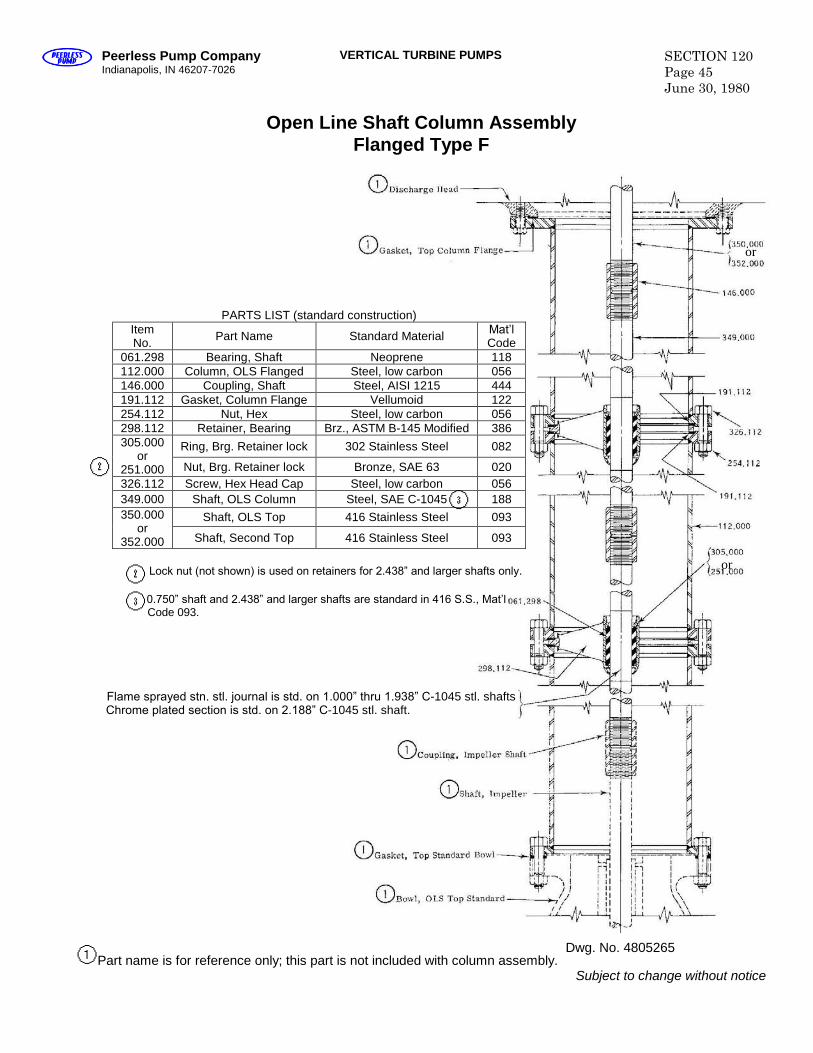
Peerless Pump CompanyIndianapolis, IN 46207-7026
VERTICAL TURBINE PUMPS SECTION 120Page 45June 30, 1980
Open Line Shaft Column AssemblyFlanged Type F
PARTS LIST (standard construction)ItemNo. Part Name Standard Material Mat’l
Code061.298 Bearing, Shaft Neoprene 118112.000 Column, OLS Flanged Steel, low carbon 056146.000 Coupling, Shaft Steel, AISI 1215 444191.112 Gasket, Column Flange Vellumoid 122254.112 Nut, Hex Steel, low carbon 056298.112 Retainer, Bearing Brz., ASTM B-145 Modified 386
Ring, Brg. Retainer lock 302 Stainless Steel 082305.000or
251.000 Nut, Brg. Retainer lock Bronze, SAE 63 020326.112 Screw, Hex Head Cap Steel, low carbon 056349.000 Shaft, OLS Column Steel, SAE C-1045 188
Shaft, OLS Top 416 Stainless Steel 093350.000or
352.000 Shaft, Second Top 416 Stainless Steel 093
Lock nut (not shown) is used on retainers for 2.438” and larger shafts only.
0.750” shaft and 2.438” and larger shafts are standard in 416 S.S., Mat’l Code 093.
Flame sprayed stn. stl. journal is std. on 1.000” thru 1.938” C-1045 stl. shaftsChrome plated section is std. on 2.188” C-1045 stl. shaft.
Part name is for reference only; this part is not included with column assembly.Subject to change without notice
or
or
Dwg. No. 4805265
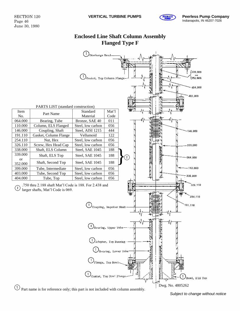
SECTION 120Page 46June 30, 1980
VERTICAL TURBINE PUMPS Peerless Pump CompanyIndianapolis, IN 46207-7026
Enclosed Line Shaft Column AssemblyFlanged Type F
.750 thru 2.188 shaft Mat’l Code is 188. For 2.438 and larger shafts, Mat’l Code is 069.
Part name is for reference only; this part is not included with column assembly.Subject to change without notice
PARTS LIST (standard construction)ItemNo. Part Name Standard
MaterialMat’lCode
064.000 Bearing, Tube Bronze, SAE 40 011110.000 Column, ELS Flanged Steel, low carbon 056146.000 Coupling, Shaft Steel, AISI 1215 444191.110 Gasket, Column Flange Vellumoid 122254.110 Nut, Hex Steel, low carbon 056326.110 Screw, Hex Head Cap Steel, low carbon 056338.000 Shaft, ELS Column Steel, SAE 1045 188
Shaft, ELS Top Steel, SAE 1045 188339.000or
352.000 Shaft, Second Top Steel, SAE 1045 188
399.000 Tube, Intermediate Steel, low carbon 056403.000 Tube, Second Top Steel, low carbon 056404.000 Tube, Top Steel, low carbon 056
}
Dwg. No. 4805262
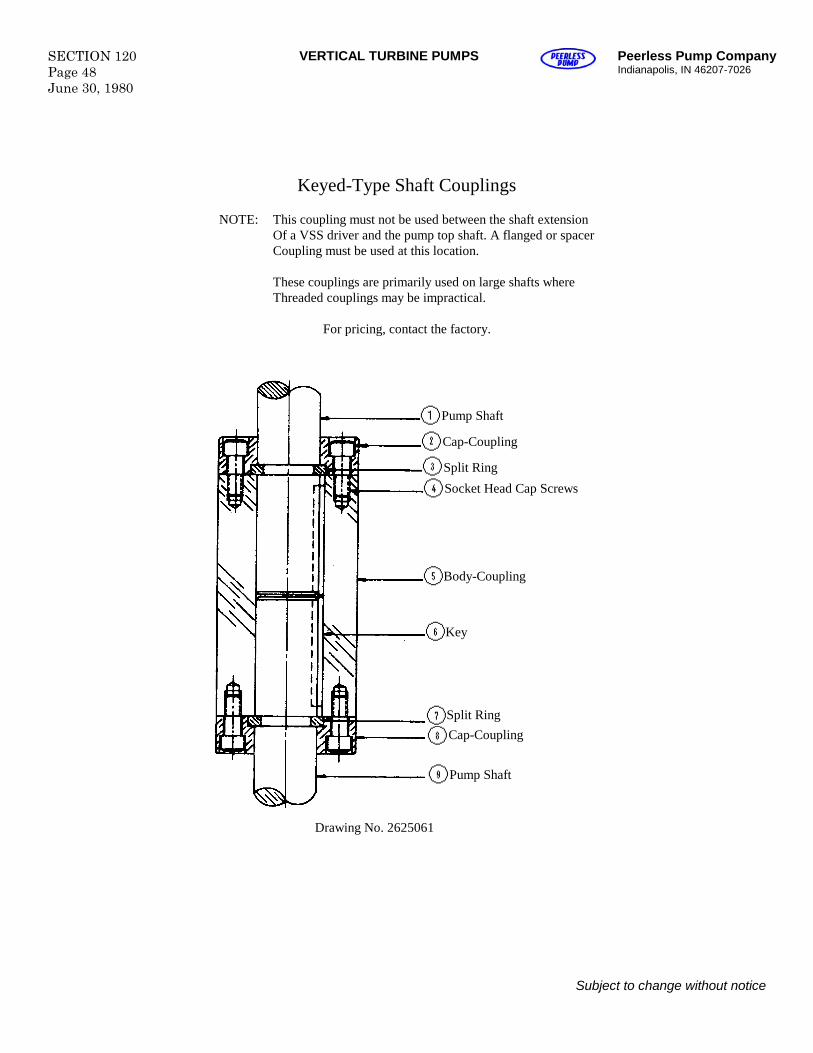
SECTION 120Page 48June 30, 1980
VERTICAL TURBINE PUMPS Peerless Pump CompanyIndianapolis, IN 46207-7026
Keyed-Type Shaft Couplings
NOTE: This coupling must not be used between the shaft extensionOf a VSS driver and the pump top shaft. A flanged or spacerCoupling must be used at this location.
These couplings are primarily used on large shafts whereThreaded couplings may be impractical.
For pricing, contact the factory.
Subject to change without notice
Cap-Coupling
Pump Shaft
Split Ring
Socket Head Cap Screws
Body-Coupling
Key
Split RingCap-Coupling
Pump Shaft
Drawing No. 2625061
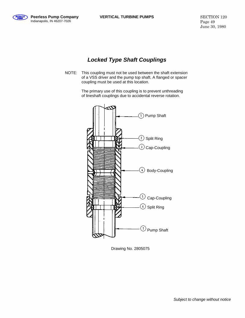
Peerless Pump CompanyIndianapolis, IN 46207-7026
VERTICAL TURBINE PUMPS SECTION 120Page 49June 30, 1980
Locked Type Shaft Couplings
Pump Shaft
Split Ring
Cap-Coupling
Body-Coupling
Cap-Coupling
Split Ring
Pump Shaft
Drawing No. 2805075
Subject to change without notice
NOTE: This coupling must not be used between the shaft extensionof a VSS driver and the pump top shaft. A flanged or spacercoupling must be used at this location.
The primary use of this coupling is to prevent unthreadingof lineshaft couplings due to accidental reverse rotation.
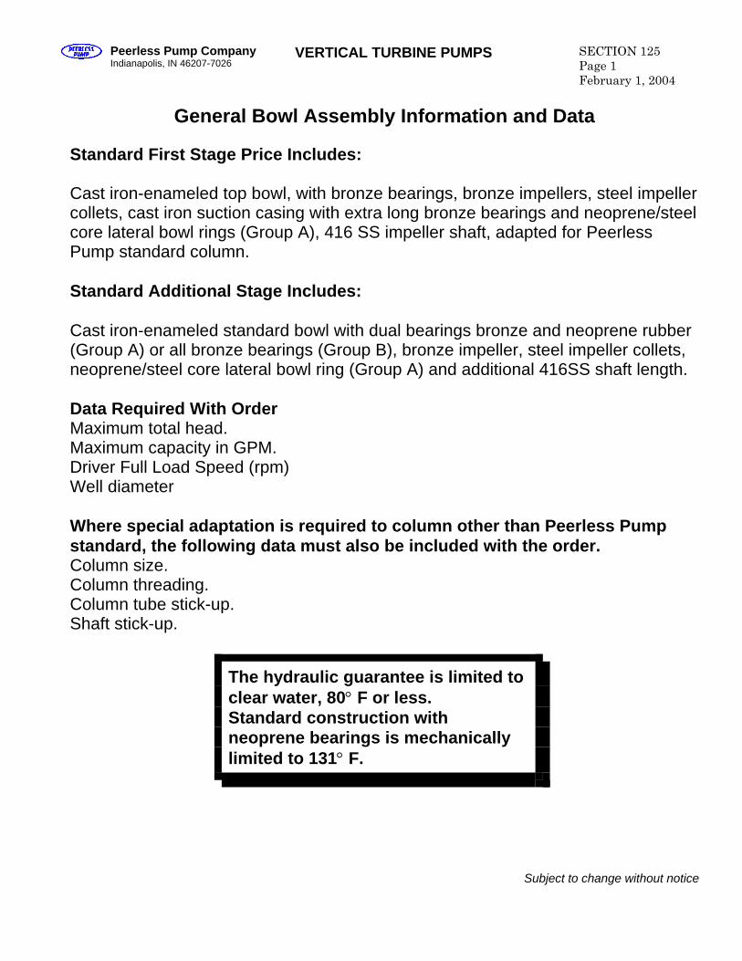
Peerless Pump Company Indianapolis, IN 46207-7026
VERTICAL TURBINE PUMPS SECTION 125 Page 1 February 1, 2004
General Bowl Assembly Information and Data
Standard First Stage Price Includes: Cast iron-enameled top bowl, with bronze bearings, bronze impellers, steel impeller collets, cast iron suction casing with extra long bronze bearings and neoprene/steel core lateral bowl rings (Group A), 416 SS impeller shaft, adapted for Peerless Pump standard column. Standard Additional Stage Includes: Cast iron-enameled standard bowl with dual bearings bronze and neoprene rubber (Group A) or all bronze bearings (Group B), bronze impeller, steel impeller collets, neoprene/steel core lateral bowl ring (Group A) and additional 416SS shaft length. Data Required With Order Maximum total head. Maximum capacity in GPM. Driver Full Load Speed (rpm) Well diameter Where special adaptation is required to column other than Peerless Pump standard, the following data must also be included with the order. Column size. Column threading. Column tube stick-up. Shaft stick-up.
The hydraulic guarantee is limited to clear water, 80° F or less. Standard construction with neoprene bearings is mechanically limited to 131° F.
Subject to change without notice
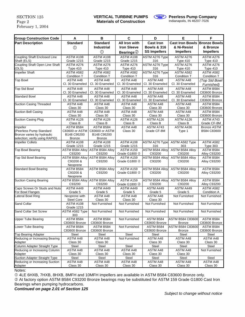
SECTION 125 Page 2 February 1, 2004
VERTICAL TURBINE PUMPS Materials of Construction
Peerless Pump Company Indianapolis, IN 46207-7026
Group Construction Code A B C D E F Part Description Standard
Standard Industrial
All Iron with Iron Sleeve Bearings
Cast Iron Bowls & 316 SS Impellers
Cast Iron Bowls & Ni-Resist Impellers
Bronze Bowls & Bronze Impellers
Coupling Shaft Enclosed Line Shaft (ELS)
ASTM A108 Grade 1215
ASTM A108 Grade 1215
ASTM A108 Grade 1215
ASTM A276 Type 316
ASTM A276 Type 410
ASTM A276 Type 410
Coupling Shaft Open Line Shaft (OLS)
ASTM A276 Type 410
ASTM A276 Type 410
ASTM A276 Type 410
ASTM A276 Type 316
ASTM A276 Type 410
ASTM A276 Type 410
Impeller Shaft ASTM A582 Condition T
ASTM A582 Condition T
ASTM A582 Condition T
ASTM A276 Type 316
ASTM A582 Condition T
ASTM A582 Condition T
Top Bowl ASTM A48 Cl. 30 Enameled
ASTM A48 Cl. 30 Enameled
ASTM A48 Cl. 30 Enameled
ASTM A48 Cl. 30 Enameled
ASTM A48 Cl. 30 Enameled
(Top Std Bowl Furnished)
Top Std Bowl ASTM A48 Cl. 30 Enameled
ASTM A48 Cl. 30 Enameled
ASTM A48 Cl. 30 Enameled
ASTM A48 Cl. 30 Enameled
ASTM A48 Cl. 30 Enameled
ASTM B584 C83600 Bronze
Standard Bowl ASTM A48 Cl. 30 Enameled
ASTM A48 Cl. 30 Enameled
ASTM A48 Cl. 30 Enameled
ASTM A48 Cl. 30 Enameled
ASTM A48 Cl. 30 Enameled
ASTM B584 C83600 Bronze
Suction Casing Threaded ASTM A48 Class 30
ASTM A48 Class 30
ASTM A48 Class 30
ASTM A48 Class 30
ASTM A48 Class 30
ASTM B584 C83600 Bronze
Suction Bell Casing ASTM A48 Class 30
ASTM A48 Class 30
ASTM A48 Class 30
ASTM A48 Class 30
ASTM A48 Class 30
ASTM B584 C83600 Bronze
Suction Casing Plug ASTM A126 Class B
ASTM A126 Class B
ASTM A126 Class B
ASTM A126 Class B
ASTM A126 Class B
ASTM A743 Grade CF-8M
Impeller (Peerless Pump Standard Bronze varies by hydraulic selection; verify using RAPID)
ASTM B584 C83600 or ASTM
B148 C95200 Bronze
ASTM B584 C83600 or ASTM
B148 C95200 Bronze
ASTM A48 Class 30
ASTM A743 Grade CF-8M
ASTM A436 Type 1
Bronze ASTM B584 C83600
Impeller Collets ASTM A108 Grade 1215
ASTM A108 Grade 1215
ASTM A108 Grade 1215
ASTM A276 Type 316
ASTM A582 Type 303
ASTM A582 Type 303
Top Bowl Bearing ASTM B584 Alloy C93200
ASTM B584 Alloy C93200
ASTM A159 Grade G1800
ASTM B584 Alloy C93200
ASTM B584 Alloy C93200
ASTM B584 Alloy C93200
Top Std Bowl Bearing ASTM B584 Alloy C93200 & Neoprene
ASTM B584 Alloy C93200
ASTM A159 Grade G1800
ASTM B584 Alloy C93200
ASTM B584 Alloy C93200
ASTM B584 Alloy C93200
Standard Bowl Bearing ASTM B584 C93200 & Neoprene
ASTM B584 Alloy C93200
ASTM A159 Grade G1800
ASTM B584 Alloy C93200
ASTM B584 Alloy C93200
ASTM B584 Alloy C93200
Suction Casing Bearing ASTM B584 Alloy C93200
ASTM B584 Alloy C93200
ASTM A159 Grade G1800
ASTM B584 Alloy C93200
ASTM B584 Alloy C93200
ASTM B584 Alloy C93200
Caps Screws Or Studs and Nuts For Bowl Flanges
ASTM A449 Grade 5
ASTM A449 Grade 5
ASTM A449 Grade 5
ASTM A449 Grade 5
ASTM A449 Grade 5
ASTM A582 Condition A
Lateral Bowl Ring Neoprene with Steel Core
ASTM A48 Class 30
ASTM A48 Class 30
ASTM A48 Class 30
Not Furnished Not Furnished
Sand Collar ASTM A108 Grade 1215
Not Furnished Not Furnished Not Furnished Not Furnished Not Furnished
Sand Collar Set Screw ASTM A582 Type 303
Not Furnished Not Furnished Not Furnished Not Furnished Not Furnished
Upper Tube Bearing ASTM B584 C83600 Bronze
ASTM B584 C83600 Bronze
Not Furnished ASTM B584 C83600 Bronze
ASTM B584 C83600 Bronze
ASTM B584 C83600 Bronze
Lower Tube Bearing ASTM B584 C83600 Bronze
ASTM B584 C83600 Bronze
Not Furnished ASTM B584 C83600 Bronze
ASTM B584 C83600 Bronze
ASTM B584 C83600 Bronze
Top Bearing Adapter Steel Steel Steel Steel Steel Steel Reducing or Increasing Bearing Adapter
ASTM A48 Class 30
ASTM A48 Class 30
Not Furnished ASTM A48 Class 30
ASTM A48 Class 30
ASTM A48 Class 30
Column Adapter Straight Type Steel Steel Steel Steel Steel Steel Reducing or Increasing Column Adapter
ASTM A48 Class 30
ASTM A48 Class 30
ASTM A48 Class 30
ASTM A48 Class 30
ASTM A48 Class 30
Not Furnished
Suction Adapter Straight Type Steel Steel Steel Steel Steel Steel Reducing or Increasing Suction Adapter
ASTM A48 Class 30
ASTM A48 Class 30
ASTM A48 Class 30
ASTM A48 Class 30
ASTM A48 Class 30
ASTM A48 Class 30
Notes: 4LE 6HXB, 7HXB, 8HXB, 8MFH and 10MFH impellers are available in ASTM B584 C83600 Bronze only. At factory option ASTM B584 C93200 Bronze bearings may be substituted for ASTM 159 Grade G1800 Cast Iron
Bearings when pumping hydrocarbons. Continued on page 2.01 of Section 125
Subject to change without notice
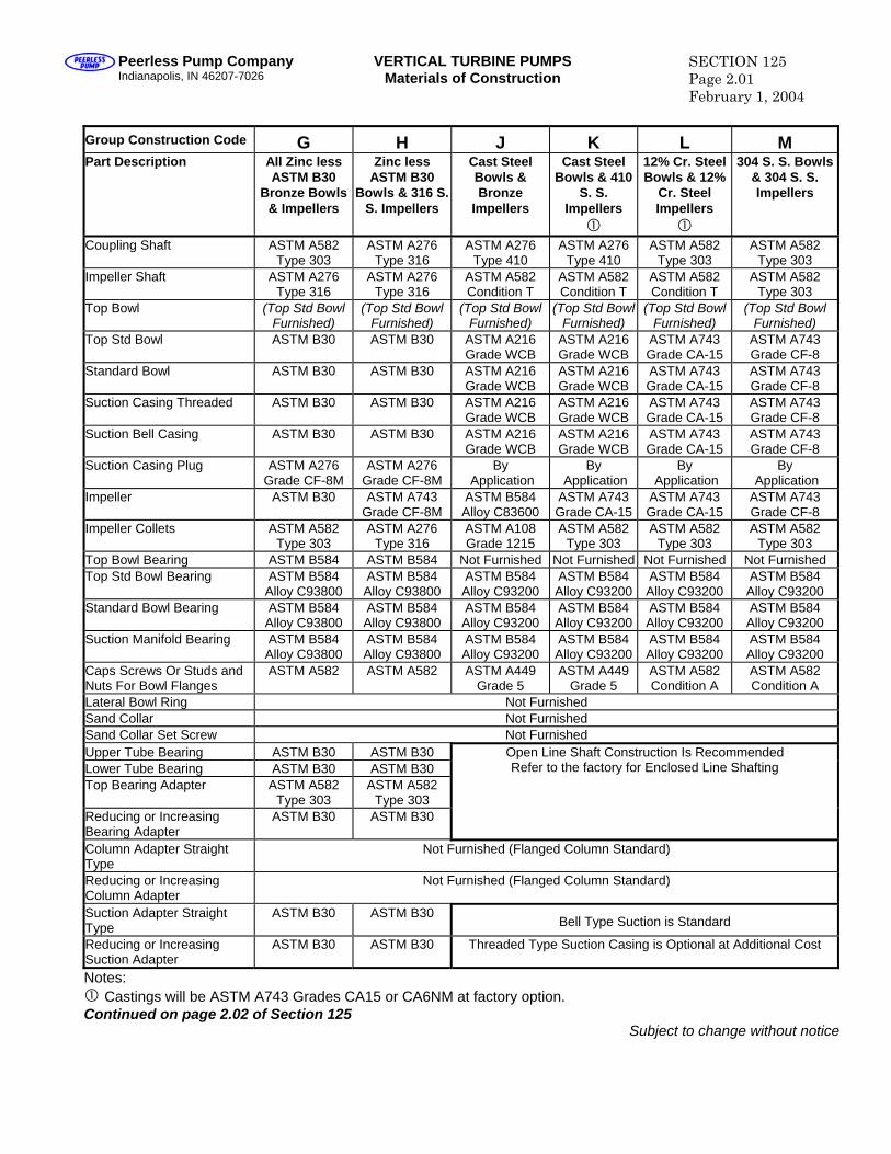
Peerless Pump Company Indianapolis, IN 46207-7026
VERTICAL TURBINE PUMPS Materials of Construction
SECTION 125 Page 2.01 February 1, 2004
Group Construction Code G H J K L M Part Description All Zinc less
ASTM B30 Bronze Bowls
& Impellers
Zinc less ASTM B30
Bowls & 316 S. S. Impellers
Cast Steel Bowls & Bronze
Impellers
Cast Steel Bowls & 410
S. S. Impellers
12% Cr. Steel Bowls & 12%
Cr. Steel Impellers
304 S. S. Bowls & 304 S. S. Impellers
Coupling Shaft ASTM A582 Type 303
ASTM A276 Type 316
ASTM A276 Type 410
ASTM A276 Type 410
ASTM A582 Type 303
ASTM A582 Type 303
Impeller Shaft ASTM A276 Type 316
ASTM A276 Type 316
ASTM A582 Condition T
ASTM A582 Condition T
ASTM A582 Condition T
ASTM A582 Type 303
Top Bowl (Top Std Bowl Furnished)
(Top Std Bowl Furnished)
(Top Std Bowl Furnished)
(Top Std Bowl Furnished)
(Top Std Bowl Furnished)
(Top Std Bowl Furnished)
Top Std Bowl ASTM B30 ASTM B30 ASTM A216 Grade WCB
ASTM A216 Grade WCB
ASTM A743 Grade CA-15
ASTM A743 Grade CF-8
Standard Bowl ASTM B30 ASTM B30 ASTM A216 Grade WCB
ASTM A216 Grade WCB
ASTM A743 Grade CA-15
ASTM A743 Grade CF-8
Suction Casing Threaded ASTM B30 ASTM B30 ASTM A216 Grade WCB
ASTM A216 Grade WCB
ASTM A743 Grade CA-15
ASTM A743 Grade CF-8
Suction Bell Casing ASTM B30 ASTM B30 ASTM A216 Grade WCB
ASTM A216 Grade WCB
ASTM A743 Grade CA-15
ASTM A743 Grade CF-8
Suction Casing Plug ASTM A276 Grade CF-8M
ASTM A276 Grade CF-8M
By Application
By Application
By Application
By Application
Impeller ASTM B30 ASTM A743 Grade CF-8M
ASTM B584 Alloy C83600
ASTM A743 Grade CA-15
ASTM A743 Grade CA-15
ASTM A743 Grade CF-8
Impeller Collets ASTM A582 Type 303
ASTM A276 Type 316
ASTM A108 Grade 1215
ASTM A582 Type 303
ASTM A582 Type 303
ASTM A582 Type 303
Top Bowl Bearing ASTM B584 ASTM B584 Not Furnished Not Furnished Not Furnished Not Furnished Top Std Bowl Bearing ASTM B584
Alloy C93800 ASTM B584 Alloy C93800
ASTM B584 Alloy C93200
ASTM B584 Alloy C93200
ASTM B584 Alloy C93200
ASTM B584 Alloy C93200
Standard Bowl Bearing ASTM B584 Alloy C93800
ASTM B584 Alloy C93800
ASTM B584 Alloy C93200
ASTM B584 Alloy C93200
ASTM B584 Alloy C93200
ASTM B584 Alloy C93200
Suction Manifold Bearing ASTM B584 Alloy C93800
ASTM B584 Alloy C93800
ASTM B584 Alloy C93200
ASTM B584 Alloy C93200
ASTM B584 Alloy C93200
ASTM B584 Alloy C93200
Caps Screws Or Studs and Nuts For Bowl Flanges
ASTM A582 ASTM A582 ASTM A449 Grade 5
ASTM A449 Grade 5
ASTM A582 Condition A
ASTM A582 Condition A
Lateral Bowl Ring Not Furnished Sand Collar Not Furnished Sand Collar Set Screw Not Furnished Upper Tube Bearing ASTM B30 ASTM B30 Lower Tube Bearing ASTM B30 ASTM B30 Top Bearing Adapter ASTM A582
Type 303 ASTM A582
Type 303 Reducing or Increasing Bearing Adapter
ASTM B30 ASTM B30
Open Line Shaft Construction Is Recommended Refer to the factory for Enclosed Line Shafting
Column Adapter Straight Type
Not Furnished (Flanged Column Standard)
Reducing or Increasing Column Adapter
Not Furnished (Flanged Column Standard)
Suction Adapter Straight Type
ASTM B30 ASTM B30 Bell Type Suction is Standard
Reducing or Increasing Suction Adapter
ASTM B30 ASTM B30 Threaded Type Suction Casing is Optional at Additional Cost
Notes: Castings will be ASTM A743 Grades CA15 or CA6NM at factory option.
Continued on page 2.02 of Section 125 Subject to change without notice
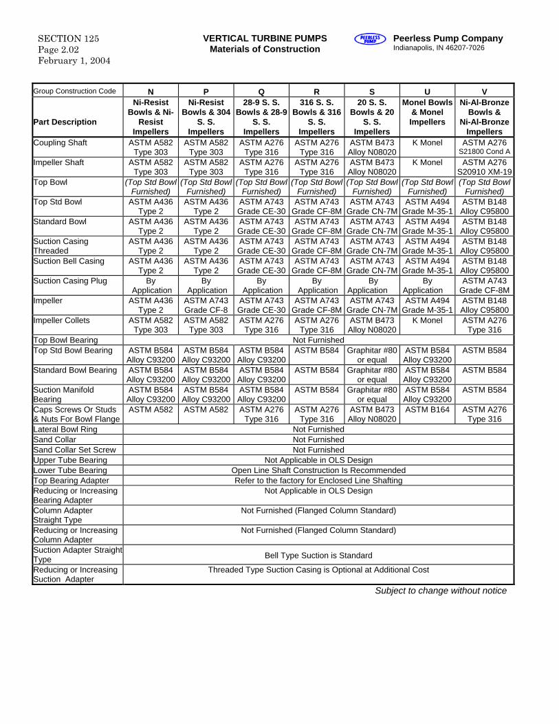
SECTION 125 Page 2.02 February 1, 2004
VERTICAL TURBINE PUMPS Materials of Construction
Peerless Pump Company Indianapolis, IN 46207-7026
Group Construction Code N P Q R S U V Part Description
Ni-Resist Bowls & Ni-
Resist Impellers
Ni-Resist Bowls & 304
S. S. Impellers
28-9 S. S. Bowls & 28-9
S. S. Impellers
316 S. S. Bowls & 316
S. S. Impellers
20 S. S. Bowls & 20
S. S. Impellers
Monel Bowls & Monel Impellers
Ni-Al-Bronze Bowls &
Ni-Al-Bronze Impellers
Coupling Shaft ASTM A582 Type 303
ASTM A582 Type 303
ASTM A276 Type 316
ASTM A276 Type 316
ASTM B473 Alloy N08020
K Monel ASTM A276 S21800 Cond A
Impeller Shaft ASTM A582 Type 303
ASTM A582 Type 303
ASTM A276 Type 316
ASTM A276 Type 316
ASTM B473 Alloy N08020
K Monel ASTM A276 S20910 XM-19
Top Bowl (Top Std Bowl Furnished)
(Top Std Bowl Furnished)
(Top Std Bowl Furnished)
(Top Std Bowl Furnished)
(Top Std Bowl Furnished)
(Top Std Bowl Furnished)
(Top Std Bowl Furnished)
Top Std Bowl ASTM A436 Type 2
ASTM A436 Type 2
ASTM A743 Grade CE-30
ASTM A743 Grade CF-8M
ASTM A743 Grade CN-7M
ASTM A494 Grade M-35-1
ASTM B148 Alloy C95800
Standard Bowl ASTM A436 Type 2
ASTM A436 Type 2
ASTM A743 Grade CE-30
ASTM A743 Grade CF-8M
ASTM A743 Grade CN-7M
ASTM A494 Grade M-35-1
ASTM B148 Alloy C95800
Suction Casing Threaded
ASTM A436 Type 2
ASTM A436 Type 2
ASTM A743 Grade CE-30
ASTM A743 Grade CF-8M
ASTM A743 Grade CN-7M
ASTM A494 Grade M-35-1
ASTM B148 Alloy C95800
Suction Bell Casing ASTM A436 Type 2
ASTM A436 Type 2
ASTM A743 Grade CE-30
ASTM A743 Grade CF-8M
ASTM A743 Grade CN-7M
ASTM A494 Grade M-35-1
ASTM B148 Alloy C95800
Suction Casing Plug By Application
By Application
By Application
By Application
By Application
By Application
ASTM A743 Grade CF-8M
Impeller ASTM A436 Type 2
ASTM A743 Grade CF-8
ASTM A743 Grade CE-30
ASTM A743 Grade CF-8M
ASTM A743 Grade CN-7M
ASTM A494 Grade M-35-1
ASTM B148 Alloy C95800
Impeller Collets ASTM A582 Type 303
ASTM A582 Type 303
ASTM A276 Type 316
ASTM A276 Type 316
ASTM B473 Alloy N08020
K Monel ASTM A276 Type 316
Top Bowl Bearing Not Furnished Top Std Bowl Bearing ASTM B584
Alloy C93200 ASTM B584 Alloy C93200
ASTM B584 Alloy C93200
ASTM B584 Graphitar #80 or equal
ASTM B584 Alloy C93200
ASTM B584
Standard Bowl Bearing ASTM B584 Alloy C93200
ASTM B584 Alloy C93200
ASTM B584 Alloy C93200
ASTM B584 Graphitar #80 or equal
ASTM B584 Alloy C93200
ASTM B584
Suction Manifold Bearing
ASTM B584 Alloy C93200
ASTM B584 Alloy C93200
ASTM B584 Alloy C93200
ASTM B584 Graphitar #80 or equal
ASTM B584 Alloy C93200
ASTM B584
Caps Screws Or Studs & Nuts For Bowl Flange
ASTM A582 ASTM A582 ASTM A276 Type 316
ASTM A276 Type 316
ASTM B473 Alloy N08020
ASTM B164 ASTM A276 Type 316
Lateral Bowl Ring Not Furnished Sand Collar Not Furnished Sand Collar Set Screw Not Furnished Upper Tube Bearing Not Applicable in OLS Design Lower Tube Bearing Open Line Shaft Construction Is Recommended Top Bearing Adapter Refer to the factory for Enclosed Line Shafting Reducing or Increasing Bearing Adapter
Not Applicable in OLS Design
Column Adapter Straight Type
Not Furnished (Flanged Column Standard)
Reducing or Increasing Column Adapter
Not Furnished (Flanged Column Standard)
Suction Adapter Straight Type Bell Type Suction is Standard
Reducing or Increasing Suction Adapter
Threaded Type Suction Casing is Optional at Additional Cost
Subject to change without notice

Blank
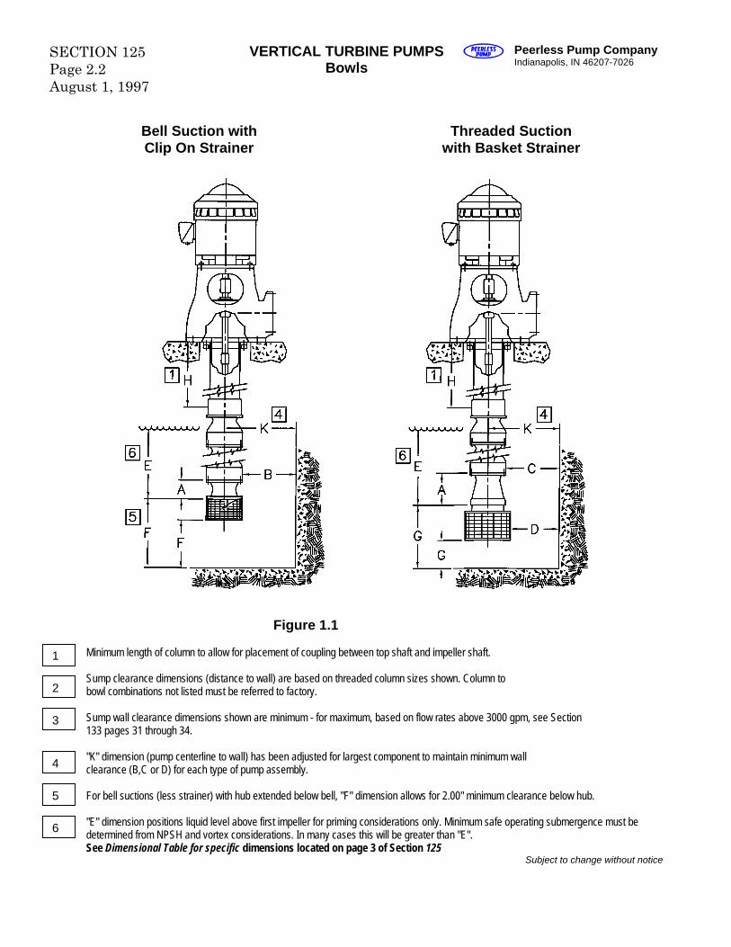
SECTION 125 Page 2.2 August 1, 1997
VERTICAL TURBINE PUMPS Bowls
Peerless Pump Company Indianapolis, IN 46207-7026
Bell Suction with Clip On Strainer
Threaded Suction with Basket Strainer
Figure 1.1
Minimum length of column to allow for placement of coupling between top shaft and impeller shaft.
1
Sump clearance dimensions (distance to wall) are based on threaded column sizes shown. Column to bowl combinations not listed must be referred to factory.
2Sump wall clearance dimensions shown are minimum - for maximum, based on flow rates above 3000 gpm, see Section
3 133 pages 31 through 34."K" dimension (pump centerline to wall) has been adjusted for largest component to maintain minimum wall clearance (B,C or D) for each type of pump assembly.
4For bell suctions (less strainer) with hub extended below bell, "F" dimension allows for 2.00" minimum clearance below hub.
5"E" dimension positions liquid level above first impeller for priming considerations only. Minimum safe operating submergence must be
6 determined from NPSH and vortex considerations. In many cases this will be greater than "E". See Dimensional Table for specific dimensions located on page 3 of Section 125Subject to change without notice
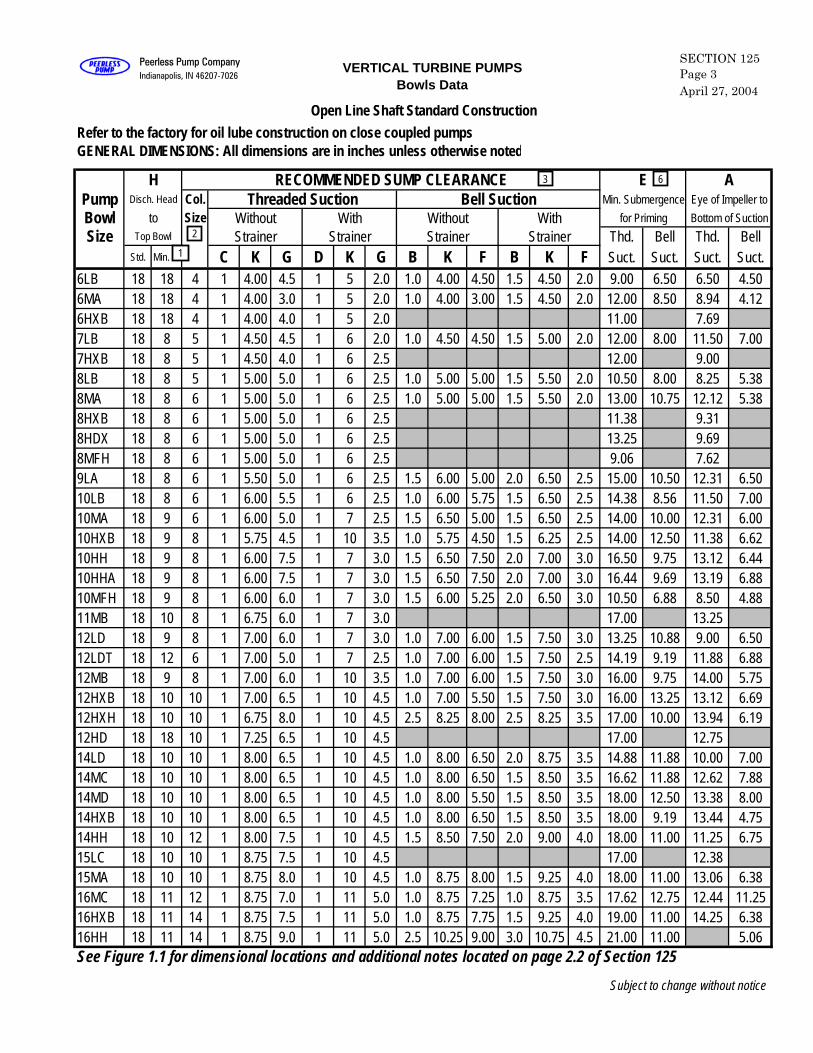
Open Line Shaft Standard ConstructionRefer to the factory for oil lube construction on close coupled pumpsGENERAL DIMENSIONS: All dimensions are in inches unless otherwise noted
H RECOMMENDED SUMP CLEARANCE E APump Disch. Head Col. Threaded Suction Bell Suction Min. Submergence Eye of Impeller to
Bowl to Size Without With Without With for Priming Bottom of Suction
Size Top Bowl Strainer Strainer Strainer Strainer Thd. Bell Thd. BellStd. Min. C K G D K G B K F B K F Suct. Suct. Suct. Suct.
6LB 18 18 4 1 4.00 4.5 1 5 2.0 1.0 4.00 4.50 1.5 4.50 2.0 9.00 6.50 6.50 4.506MA 18 18 4 1 4.00 3.0 1 5 2.0 1.0 4.00 3.00 1.5 4.50 2.0 12.00 8.50 8.94 4.126HXB 18 18 4 1 4.00 4.0 1 5 2.0 11.00 7.697LB 18 8 5 1 4.50 4.5 1 6 2.0 1.0 4.50 4.50 1.5 5.00 2.0 12.00 8.00 11.50 7.007HXB 18 8 5 1 4.50 4.0 1 6 2.5 12.00 9.008LB 18 8 5 1 5.00 5.0 1 6 2.5 1.0 5.00 5.00 1.5 5.50 2.0 10.50 8.00 8.25 5.388MA 18 8 6 1 5.00 5.0 1 6 2.5 1.0 5.00 5.00 1.5 5.50 2.0 13.00 10.75 12.12 5.388HXB 18 8 6 1 5.00 5.0 1 6 2.5 11.38 9.318HDX 18 8 6 1 5.00 5.0 1 6 2.5 13.25 9.698MFH 18 8 6 1 5.00 5.0 1 6 2.5 9.06 7.629LA 18 8 6 1 5.50 5.0 1 6 2.5 1.5 6.00 5.00 2.0 6.50 2.5 15.00 10.50 12.31 6.5010LB 18 8 6 1 6.00 5.5 1 6 2.5 1.0 6.00 5.75 1.5 6.50 2.5 14.38 8.56 11.50 7.0010MA 18 9 6 1 6.00 5.0 1 7 2.5 1.5 6.50 5.00 1.5 6.50 2.5 14.00 10.00 12.31 6.0010HXB 18 9 8 1 5.75 4.5 1 10 3.5 1.0 5.75 4.50 1.5 6.25 2.5 14.00 12.50 11.38 6.6210HH 18 9 8 1 6.00 7.5 1 7 3.0 1.5 6.50 7.50 2.0 7.00 3.0 16.50 9.75 13.12 6.4410HHA 18 9 8 1 6.00 7.5 1 7 3.0 1.5 6.50 7.50 2.0 7.00 3.0 16.44 9.69 13.19 6.8810MFH 18 9 8 1 6.00 6.0 1 7 3.0 1.5 6.00 5.25 2.0 6.50 3.0 10.50 6.88 8.50 4.8811MB 18 10 8 1 6.75 6.0 1 7 3.0 17.00 13.2512LD 18 9 8 1 7.00 6.0 1 7 3.0 1.0 7.00 6.00 1.5 7.50 3.0 13.25 10.88 9.00 6.5012LDT 18 12 6 1 7.00 5.0 1 7 2.5 1.0 7.00 6.00 1.5 7.50 2.5 14.19 9.19 11.88 6.8812MB 18 9 8 1 7.00 6.0 1 10 3.5 1.0 7.00 6.00 1.5 7.50 3.0 16.00 9.75 14.00 5.7512HXB 18 10 10 1 7.00 6.5 1 10 4.5 1.0 7.00 5.50 1.5 7.50 3.0 16.00 13.25 13.12 6.6912HXH 18 10 10 1 6.75 8.0 1 10 4.5 2.5 8.25 8.00 2.5 8.25 3.5 17.00 10.00 13.94 6.1912HD 18 18 10 1 7.25 6.5 1 10 4.5 17.00 12.7514LD 18 10 10 1 8.00 6.5 1 10 4.5 1.0 8.00 6.50 2.0 8.75 3.5 14.88 11.88 10.00 7.0014MC 18 10 10 1 8.00 6.5 1 10 4.5 1.0 8.00 6.50 1.5 8.50 3.5 16.62 11.88 12.62 7.8814MD 18 10 10 1 8.00 6.5 1 10 4.5 1.0 8.00 5.50 1.5 8.50 3.5 18.00 12.50 13.38 8.0014HXB 18 10 10 1 8.00 6.5 1 10 4.5 1.0 8.00 6.50 1.5 8.50 3.5 18.00 9.19 13.44 4.7514HH 18 10 12 1 8.00 7.5 1 10 4.5 1.5 8.50 7.50 2.0 9.00 4.0 18.00 11.00 11.25 6.7515LC 18 10 10 1 8.75 7.5 1 10 4.5 17.00 12.3815MA 18 10 10 1 8.75 8.0 1 10 4.5 1.0 8.75 8.00 1.5 9.25 4.0 18.00 11.00 13.06 6.3816MC 18 11 12 1 8.75 7.0 1 11 5.0 1.0 8.75 7.25 1.0 8.75 3.5 17.62 12.75 12.44 11.2516HXB 18 11 14 1 8.75 7.5 1 11 5.0 1.0 8.75 7.75 1.5 9.25 4.0 19.00 11.00 14.25 6.3816HH 18 11 14 1 8.75 9.0 1 11 5.0 2.5 10.25 9.00 3.0 10.75 4.5 21.00 11.00 5.06See Figure 1.1 for dimensional locations and additional notes located on page 2.2 of Section 125
Subject to change without notice
SECTION 125Page 3April 27, 2004
VERTICAL TURBINE PUMPSBowls Data
Peerless Pump CompanyIndianapolis, IN 46207-7026
63
2
1
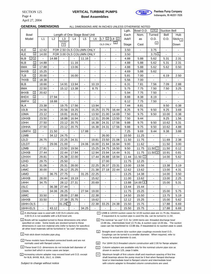
GENERAL DIMENSIONS ALL DIMENSIONS ARE IN INCHES UNLESS OTHERWISE NOTEDLgth. Bowl O.D. Suction Bell
Bowl Length of One Stage Bowl Unit Each Nom. Turned Bell HubModel L1 L2 L3 L4 L5 L6 L7 L8 Add'l as O.D. O.D. Stick
OLS ONLY
OLS ONLY Stage Cast Down
4LE 12.62 FOR 2.50 OLS COLUMN ONLY - - 3.50 - 3.75 - -4LE 14.00 FOR 3.00 OLS COLUMN ONLY - - 3.50 3.75 - -6LB - 14.88 - - 11.16 - - - 4.88 5.88 5.62 5.31 2.316LB 14.88 - - 11.16 - - - - 4.88 5.88 5.62 5.31 2.316MA 17.88 - - 13.06 - - - - 4.88 5.88 5.62 5.62 0.506HXB 15.25 - - - - - - 4.69 5.88 5.627LB 20.00 - - 16.00 - - - - 5.81 7.00 - 6.19 2.507HXB 18.38 - - - - - - 5.56 7.00 - - -8LB 18.66 - 14.91 13.94 - 10.19 - - 6.31 7.81 7.56 7.09 2.888MA 22.50 - 15.12 13.38 - 8.75 - - 5.75 7.75 7.50 7.50 3.258HXB 20.62 - - - - - - - 5.94 7.75 7.50 - -8HDX - 27.94 - - - - - - 8.88 8.38 8.19 - -8MFH - 18.88 - - - - - - 6.12 7.75 7.50 - -9LA 23.38 - 19.75 17.56 - 13.94 - - 7.44 8.81 9.50 0.3810LB 24.56 - 20.56 19.25 - 15.25 21.75 16.44 8.25 9.75 9.50 9.25 3.6910MA 23.12 - 19.81 16.81 - 13.50 21.00 14.69 7.50 9.75 9.50 10.00 0.3810HXB 23.50 - 18.88 16.94 - 12.31 20.06 13.50 7.50 9.44 9.25 1.5610HH 27.50 - 23.12 20.75 - 16.38 24.31 17.56 9.88 9.75 9.50 10.62 5.3110HHA 27.50 - 23.12 20.75 - 16.38 24.31 17.56 9.88 9.75 9.50 10.62 4.8810MFH - 21.50 - - 17.88 - - - 7.25 9.69 9.44 9.38 3.8811MB - 34.12 24.75 - - - 26.00 - 10.50 11.25 - - -12LD 26.75 - 22.25 24.31 - 19.81 23.50 21.06 11.50 11.75 - 11.69 2.3812LDT - 29.06 21.00 - 24.06 16.00 21.94 16.94 9.00 11.62 - 11.50 3.0012MB 27.81 - 23.50 19.56 - 15.25 24.75 16.50 9.50 11.75 11.50 11.50 0.1212HXB 27.44 - 22.44 17.94 - 12.94 23.94 14.44 9.31 11.75 11.50 10.91 0.8112HXH 29.81 - 25.38 22.00 - 17.44 26.88 18.94 11.44 11.50 - 14.00 5.6212HD 29.75 - 25.50 - - 27.00 11.75 12.25 - - -14LD 31.06 - 25.31 28.00 - 22.25 26.37 23.31 13.00 13.56 - 13.38 3.1914MC 30.00 - 26.12 25.25 - 21.38 27.18 22.44 12.62 13.62 - 13.00 4.3114MD - 36.75 27.75 - 31.25 22.25 - - 13.25 14.38 - 14.00 3.5014HXB 28.00 - 24.44 19.19 - 15.62 - - 11.00 13.62 - 13.00 2.2514HH 34.75 - 28.12 27.31 - 20.69 - - 13.88 14.00 - 15.00 5.3115LC - 36.38 27.44 - - - - 13.44 15.44 - - -15MA - 34.06 26.25 - 27.94 19.00 - 11.75 15.25 - 15.00 5.7516MC 33.50 - 28.00 27.88 - 22.38 - - 14.50 15.50 - 13.75 5.1916HXB 33.50 - 27.38 25.75 - 19.62 - - 12.12 15.25 - 15.00 5.6216HH-OLS - - 31.25 - - 22.38 33.25 24.38 15.50 15.75 - 17.88 6.6916HH-ELS - 43.12 - - 34.25 - - - 15.50 15.75 - 17.88 6.69 A discharge case is used with 3.00 OLS column only. 12MB & 12HXH suction cases for 10.00 suction pipe are 11.75 dia. However, 3.00 ELS is not available with a 6LB bowl unit. if requested & no suction pipe is used the dia. can be turned to 11.50.
Bowls will be supplied turned to these dimensions only when The nominal "as cast" O.D. for 14HH items are: threaded discharge bowl specified on order. Some bowls are stocked turned to these 13.88 dia., intermediate bowl 13.75 dia, & suction case 14.00 dia.. The suction dimensions in cast iron material only (refer to factory for specifics) case can be machined to 13.88 dia. if requested & no suction pipe is used. all other bowl materials will be furnished in "as cast" dimensions.
Straight steel column &/or suction pipe couplings exceeds bowl O.D.. Hub stick-down includes pipe plug. Couplings can be turned to a smaller diameter. When required, refer to
factory for actual diameter & cost. These models have threaded connected bowls and are not normally used with flanged column. For 16HH OLS threaded column construction add 2.00 for flange adapter.
These bowl O.D. dimensions do not include bell diameter of Column adapters are available only for the nominal column pipe size as suction bell which in some cases are larger. shown in section 125, page 5 table.
Increasing column adapter may exceed bowl unit O.D. except Maximum length of first column shaft and maximum spacing of first line for 6LB, 6HXB, 8LB, 15LC, & 15MA. shaft bearings above the pump must be 5 feet when flanged discharge
bowl or intermediate bowl to flanged column and intermediate bowl Subject to change without notice with column adapter to threaded column constructions are used.
1111
5 6
3
9
2
7
7
8
10
4
1 4
4
4
4
4
4
4
4
4
4
4
9
1
2
3
4
5
6
7
8
9
10
11
12
1212
Peerless Pump CompanyIndianapolis, IN 46207-7026
VERTICAL TURBINE PUMPSBowl Assemblies
SECTION 125Page 4April 27, 2004
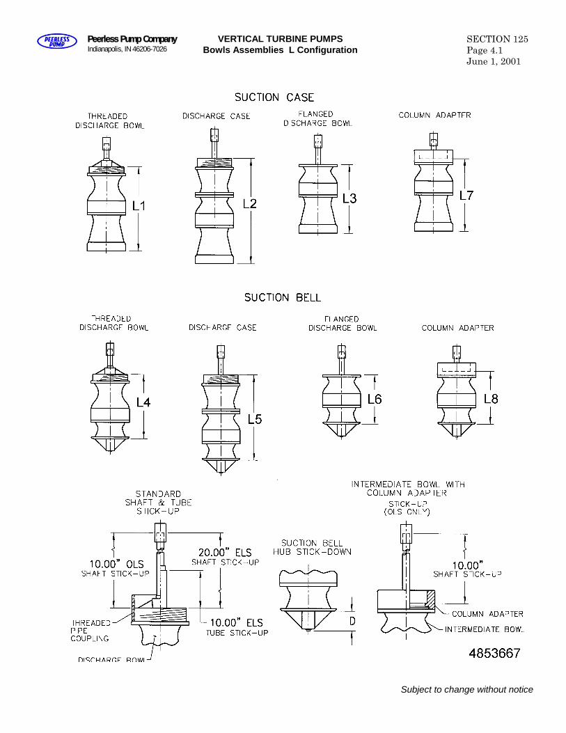
Peerless Pump CompanyIndianapolis, IN 46206-7026
VERTICAL TURBINE PUMPSBowls Assemblies L Configuration
SECTION 125Page 4.1June 1, 2001
Subject to change without notice

Blank
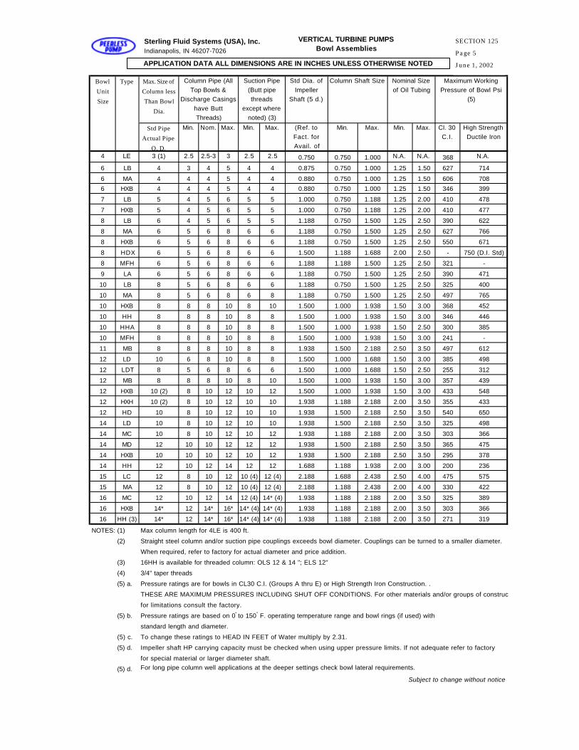
Bowl
Unit
Size
Type Max. Size of
Column less
Than Bowl
Dia.
Column Pipe (All Top Bowls &
Discharge Casings have Butt Threads)
Suction Pipe (Butt pipe threads
except where noted) (3)
Std Dia. of Impeller
Shaft (5 d.)
Column Shaft Size Nominal Size of Oil Tubing
Maximum Working Pressure of Bowl Psi
(5)
Std Pipe
Actual Pipe
O. D.
Min. Nom. Max. Min. Max. (Ref. to Fact. for Avail. of
Min. Max. Min. Max. Cl. 30 C.I.
High Strength Ductile Iron
4 LE 3 (1) 2.5 2.5-3 3 2.5 2.5 0.750 0.750 1.000 N.A. N.A. 368 N.A.
6 LB 4 3 4 5 4 4 0.875 0.750 1.000 1.25 1.50 627 714
6 MA 4 4 4 5 4 4 0.880 0.750 1.000 1.25 1.50 606 708
6 HXB 4 4 4 5 4 4 0.880 0.750 1.000 1.25 1.50 346 399
7 LB 5 4 5 6 5 5 1.000 0.750 1.188 1.25 2.00 410 478
7 HXB 5 4 5 6 5 5 1.000 0.750 1.188 1.25 2.00 410 477
8 LB 6 4 5 6 5 5 1.188 0.750 1.500 1.25 2.50 390 622
8 MA 6 5 6 8 6 6 1.188 0.750 1.500 1.25 2.50 627 766
8 HXB 6 5 6 8 6 6 1.188 0.750 1.500 1.25 2.50 550 671
8 HDX 6 5 6 8 6 6 1.500 1.188 1.688 2.00 2.50 - 750 (D.I. Std)
8 MFH 6 5 6 8 6 6 1.188 1.188 1.500 1.25 2.50 321 -
9 LA 6 5 6 8 6 6 1.188 0.750 1.500 1.25 2.50 390 471
10 LB 8 5 6 8 6 6 1.188 0.750 1.500 1.25 2.50 325 400
10 MA 8 5 6 8 6 8 1.188 0.750 1.500 1.25 2.50 497 765
10 HXB 8 8 8 10 8 10 1.500 1.000 1.938 1.50 3.00 368 452
10 HH 8 8 8 10 8 8 1.500 1.000 1.938 1.50 3.00 346 446
10 HHA 8 8 8 10 8 8 1.500 1.000 1.938 1.50 2.50 300 385
10 MFH 8 8 8 10 8 8 1.500 1.000 1.938 1.50 3.00 241 -
11 MB 8 8 8 10 8 8 1.938 1.500 2.188 2.50 3.50 497 612
12 LD 10 6 8 10 8 8 1.500 1.000 1.688 1.50 3.00 385 498
12 LDT 8 5 6 8 6 6 1.500 1.000 1.688 1.50 2.50 255 312
12 MB 8 8 8 10 8 10 1.500 1.000 1.938 1.50 3.00 357 439
12 HXB 10 (2) 8 10 12 10 12 1.500 1.000 1.938 1.50 3.00 433 548
12 HXH 10 (2) 8 10 12 10 10 1.938 1.188 2.188 2.00 3.50 355 433
12 HD 10 8 10 12 10 10 1.938 1.500 2.188 2.50 3.50 540 650
14 LD 10 8 10 12 10 10 1.938 1.500 2.188 2.50 3.50 325 498
14 MC 10 8 10 12 10 12 1.938 1.188 2.188 2.00 3.50 303 366
14 MD 12 10 10 12 12 12 1.938 1.500 2.188 2.50 3.50 365 475
14 HXB 10 10 10 12 10 12 1.938 1.500 2.188 2.50 3.50 295 378
14 HH 12 10 12 14 12 12 1.688 1.188 1.938 2.00 3.00 200 236
15 LC 12 8 10 12 10 (4) 12 (4) 2.188 1.688 2.438 2.50 4.00 475 575
15 MA 12 8 10 12 10 (4) 12 (4) 2.188 1.188 2.438 2.00 4.00 330 422
16 MC 12 10 12 14 12 (4) 14* (4) 1.938 1.188 2.188 2.00 3.50 325 389
16 HXB 14* 12 14* 16* 14* (4) 14* (4) 1.938 1.188 2.188 2.00 3.50 303 366
16 HH (3) 14* 12 14* 16* 14* (4) 14* (4) 1.938 1.188 2.188 2.00 3.50 271 319
NOTES: (1) Max column length for 4LE is 400 ft.
(2) Straight steel column and/or suction pipe couplings exceeds bowl diameter. Couplings can be turned to a smaller diameter.
When required, refer to factory for actual diameter and price addition.
(3) 16HH is available for threaded column: OLS 12 & 14 "; ELS 12"
(4) 3/4" taper threads
(5) a. Pressure ratings are for bowls in CL30 C.I. (Groups A thru E) or High Strength Iron Construction. .
THESE ARE MAXIMUM PRESSURES INCLUDING SHUT OFF CONDITIONS. For other materials and/or groups of construction
for limitations consult the factory.
(5) b. Pressure ratings are based on 0° to 150° F. operating temperature range and bowl rings (if used) with
standard length and diameter.
(5) c. To change these ratings to HEAD IN FEET of Water multiply by 2.31.
(5) d. Impeller shaft HP carrying capacity must be checked when using upper pressure limits. If not adequate refer to factory
for special material or larger diameter shaft.
(5) d. For long pipe column well applications at the deeper settings check bowl lateral requirements.
Subject to change without notice
APPLICATION DATA ALL DIMENSIONS ARE IN INCHES UNLESS OTHERWISE NOTED
Sterling Fluid Systems (USA), Inc.Indianapolis, IN 46207-7026
VERTICAL TURBINE PUMPSBowl Assemblies
SECTION 125
Page 5
June 1, 2002
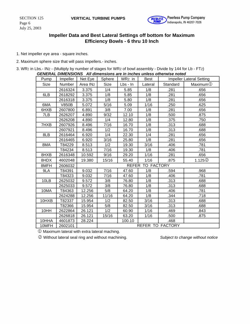
1. Net impeller eye area - square inches.
2. Maximum sphere size that will pass impellers.- inches.
3. WR2 in Lbs.- IN2 - (Multiply by number of stages for WR2 of bowl assembly - Divide by 144 for Lb - FT2)GENERAL DIMENSIONS All dimensions are in inches unless otherwise noted
Pump Impeller Net Eye Sphere WR2 in Best Impeller Lateral SettingSize Number Area IN2 Size Lbs - In Lateral Standard Maximum1
2616324 3.375 1/4 5.85 1/8 .281 .6566LB 2618292 3.375 1/8 5.85 1/8 .281 .656
2616318 3.375 1/8 5.80 1/8 .281 .6566MA V850B 5.072 5/16 5.09 1/16 .250 .6256HXB 2607800 6.891 3/8 7.00 1/8 .281 .6567LB 2626207 4.890 9/32 12.10 1/8 .500 .875
2626208 4.890 1/4 12.80 1/8 .375 .7507HXB 2607926 8.496 7/16 16.70 1/8 .313 .688
2607921 8.496 1/2 16.70 1/8 .313 .6888LB 2616464 6.920 1/4 22.30 1/4 .281 .656
2616465 6.920 3/16 25.80 1/8 .281 .6568MA T84229 8.513 1/2 19.30 3/16 .406 .781
T84234 8.513 7/16 19.30 1/8 .406 .7818HXB 2616348 10.592 9/16 29.20 1/16 .281 .6568HDX 4602048 19.380 15/16 55.40 1/16 .875 1.12528MFH 26060329LA T84391 9.032 7/16 47.60 1/8 .594 .968
T84323 9.032 7/16 47.60 1/8 .406 .78110LB 2625032 9.572 3/8 76.80 1/8 .313 .688
2625033 9.572 3/8 76.80 1/8 .313 .68810MA T84363 12.256 5/8 64.20 1/8 .406 .781
2624288 12.256 11/16 64.20 1/8 .344 .71810HXB T82337 15.954 1/2 82.50 3/16 .313 .688
T82366 15.954 5/8 82.50 3/16 .313 .68810HH 2622864 26.121 1/2 60.90 1/16 .469 .843
2626818 26.121 15/16 63.20 1/16 .500 .87510HHA 4601873 28.224 100.10 .46810MFH 26021011 Maximum lateral with extra lateral maching. 2 Without lateral seal ring and without machining. Subject to change without notice
REFER TO FACTORY
REFER TO FACTORY
VERTICAL TURBINE PUMPSSECTION 125Page 6July 25, 2003
Peerless Pump CompanyIndianapolis, IN 46207-7026
Impeller Data and Best Lateral Settings off bottom for Maximum Efficiency Bowls - 6 thru 10 Inch
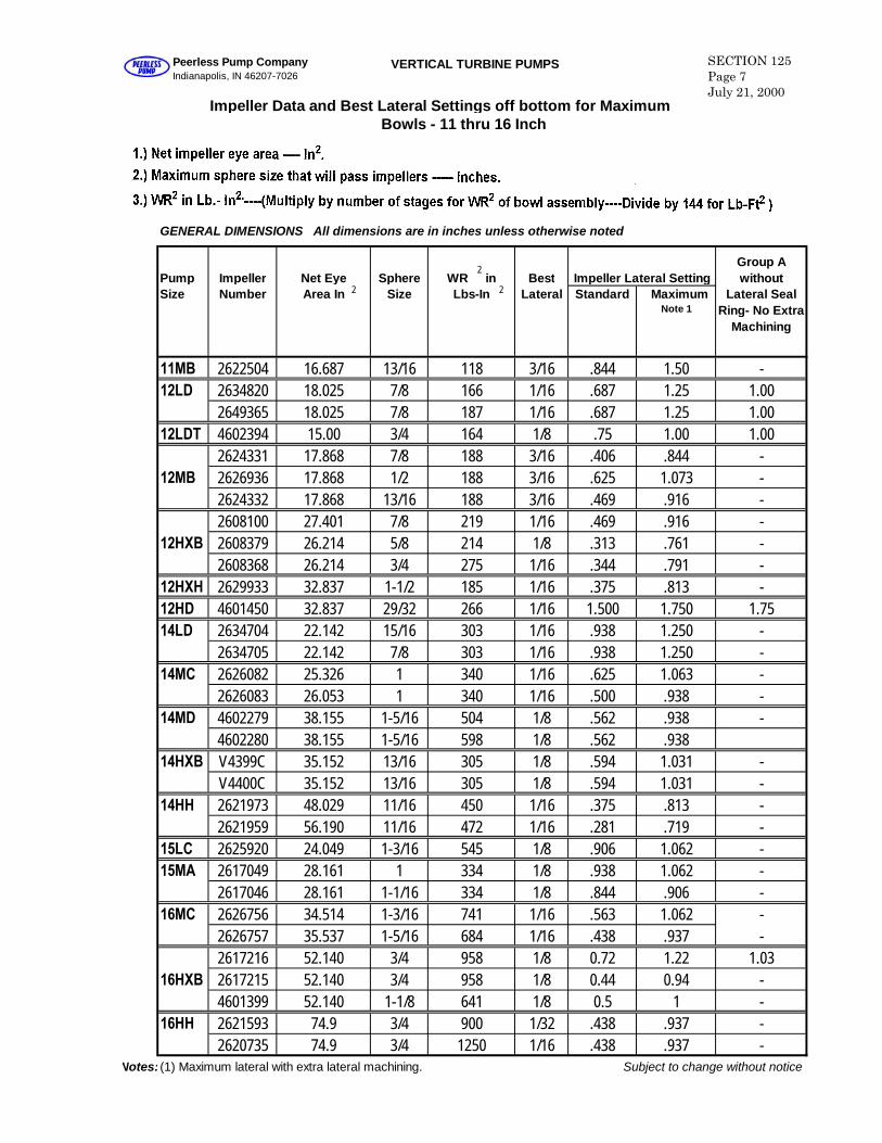
GENERAL DIMENSIONS All dimensions are in inches unless otherwise noted
Pump Impeller Net Eye Sphere WR in Best Impeller Lateral SettingGroup Awithout
Size Number Area In Size Lbs-In Lateral Standard MaximumNote 1
Lateral SealRing- No Extra
Machining
11MB 2622504 16.687 13/16 118 3/16 .844 1.50 -12LD 2634820 18.025 7/8 166 1/16 .687 1.25 1.00
2649365 18.025 7/8 187 1/16 .687 1.25 1.0012LDT 4602394 15.00 3/4 164 1/8 .75 1.00 1.00
2624331 17.868 7/8 188 3/16 .406 .844 -12MB 2626936 17.868 1/2 188 3/16 .625 1.073 -
2624332 17.868 13/16 188 3/16 .469 .916 -2608100 27.401 7/8 219 1/16 .469 .916 -
12HXB 2608379 26.214 5/8 214 1/8 .313 .761 -2608368 26.214 3/4 275 1/16 .344 .791 -
12HXH 2629933 32.837 1-1/2 185 1/16 .375 .813 -12HD 4601450 32.837 29/32 266 1/16 1.500 1.750 1.7514LD 2634704 22.142 15/16 303 1/16 .938 1.250 -
2634705 22.142 7/8 303 1/16 .938 1.250 -14MC 2626082 25.326 1 340 1/16 .625 1.063 -
2626083 26.053 1 340 1/16 .500 .938 -14MD 4602279 38.155 1-5/16 504 1/8 .562 .938 -
4602280 38.155 1-5/16 598 1/8 .562 .93814HXB V4399C 35.152 13/16 305 1/8 .594 1.031 -
V4400C 35.152 13/16 305 1/8 .594 1.031 -14HH 2621973 48.029 11/16 450 1/16 .375 .813 -
2621959 56.190 11/16 472 1/16 .281 .719 -15LC 2625920 24.049 1-3/16 545 1/8 .906 1.062 -15MA 2617049 28.161 1 334 1/8 .938 1.062 -
2617046 28.161 1-1/16 334 1/8 .844 .906 -16MC 2626756 34.514 1-3/16 741 1/16 .563 1.062 -
2626757 35.537 1-5/16 684 1/16 .438 .937 -2617216 52.140 3/4 958 1/8 0.72 1.22 1.03
16HXB 2617215 52.140 3/4 958 1/8 0.44 0.94 -4601399 52.140 1-1/8 641 1/8 0.5 1 -
16HH 2621593 74.9 3/4 900 1/32 .438 .937 -2620735 74.9 3/4 1250 1/16 .438 .937 -
Notes: (1) Maximum lateral with extra lateral machining. Subject to change without notice
VERTICAL TURBINE PUMPS SECTION 125Page 7July 21, 2000
Peerless Pump CompanyIndianapolis, IN 46207-7026
Impeller Data and Best Lateral Settings off bottom for MaximumBowls - 11 thru 16 Inch
2
2
2
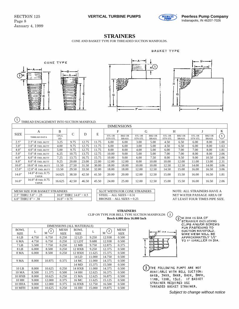
SECTION 125Page 8January 4, 1999
VERTICAL TURBINE PUMPS Peerless Pump CompanyIndianapolis, IN 46207-7026
STRAINERSCONE AND BASKET TYPE FOR THREADED SUCTION MANIFOLDS.
THREAD ENGAGEMENT INTO SUCTION MANIFOLD.DIMENSIONS
A B F G H JSIZE
THREAD DATA CPLGOD
C D E STL ORSTN STL
BRZ ORBRASS
STL ORSTN STL
BRZ ORBRASS
STL ORSTN STL
BRZ ORBRASS
STL ORSTN STL
BRZ ORBRASS
K
2.5” 2.5”-8 THD, BUTT 3.25 9.75 12.75 11.75 6.00 6.00 3.00 5.00 4.50 6.50 6.00 8.00 1.003.0” 3.0”-8 THD, BUTT 4.00 9.75 12.75 11.75 6.00 6.00 3.00 5.00 4.50 6.50 6.00 8.00 1.634.0” 4.0”-8 THD, BUTT 5.00 9.75 12.75 11.75 8.00 8.00 4.00 5.00 6.00 7.00 7.00 8.00 1.815.0” 5.0”-8 THD, BUTT 6.25 10.75 13.75 12.75 10.00 9.00 5.00 5.00 7.00 7.00 8.00 8.00 2.066.0” 6.0”-8 THD, BUTT 7.25 13.75 16.75 15.75 10.00 9.00 6.00 7.50 8.00 9.50 9.00 10.50 2.068.0” 8.0”-8 THD, BUTT 9.25 20.00 23.00 22.00 12.00 12.00 8.00 10.00 10.00 12.00 11.00 13.00 2.3110.0” 10.0”-8 THD, BUTT 11.50 27.50 31.50 30.00 18.00 18.00 10.00 10.00 12.50 12.50 14.00 14.00 3.0612.0” 12.0”-8 THD, BUTT 13.50 29.50 33.50 32.00 18.00 18.00 12.00 12.50 14.50 15.00 16.00 16.50 3.06
14.0” 14.0”-8 THD, 0.75TAPER
14.625 38.50 42.50 41.50 20.00 20.00 12.00 12.50 15.00 15.50 16.00 16.50 1.81
16.0” 16.0”-8 THD, 0.75TAPER
16.625 42.50 46.50 45.50 24.00 25.00 12.00 12.50 15.00 15.50 16.00 16.50 2.06
NOTE: ALL STRAINERS HAVE ANET WATER PASSAGE AREA OFAT LEAST FOUR TIMES PIPE SIZE.
STRAINERSCLIP ON TYPE FOR BELL TYPE SUCTION MANIFOLDS
Bowls 6.000 thru 16.000 Inch
DIMENSIONS (ALL MATERIALS)BOWLSIZE L M
MESHSIZE
BOWLSIZE L M
MESHSIZE
6 LB 4.750 6.750 0.250 12 LD 9.250 12.938 0.5006 MA 4.750 6.750 0.250 12 LDT 9.688 12.938 0.5007 LB 5.500 7.750 0.250 12 MB 9.750 12.875 0.3758 LB 6.000 8.500 0.250 12 HXB 9.250 12.375 0.5008 MA 6.000 8.500 0.250 12 HXH 11.625 15.375 0.500
14 LD 11.000 14.750 0.5009 MA 8.000 10.875 0.375 14 MC 11.000 14.375 0.500
14 MD 15.375 15.500 0.50010 LB 8.000 10.625 0.250 14 HXB 11.000 14.375 0.50010 MA 8.500 11.375 0.500 14 HH 12.625 16.375 0.500
10 HXB 8.000 10.625 0.250 15 MA 12.625 16.875 0.50010 HH 9.000 12.000 0.375 16 MC 11.625 15.125 0.500
10 HHA 9.000 12.000 0.375 16 HXB 12.750 16.500 0.50010 MFH 8.000 10.625 0.250 16 HH 15.000 19.875 0.500
Subject to change without notice
MESH SIZE FOR BASKET STRAINERS SLOT WIDTH FOR CONE STRAINERS2.5” THRU 5.0” = .25 10.0” THRU 14.0” = 0.56.0” THRU 8” = .38 16.0” = 0.75
STEEL–ALL SIZES = 0.31BRONZE–ALL SIZES = 0.25
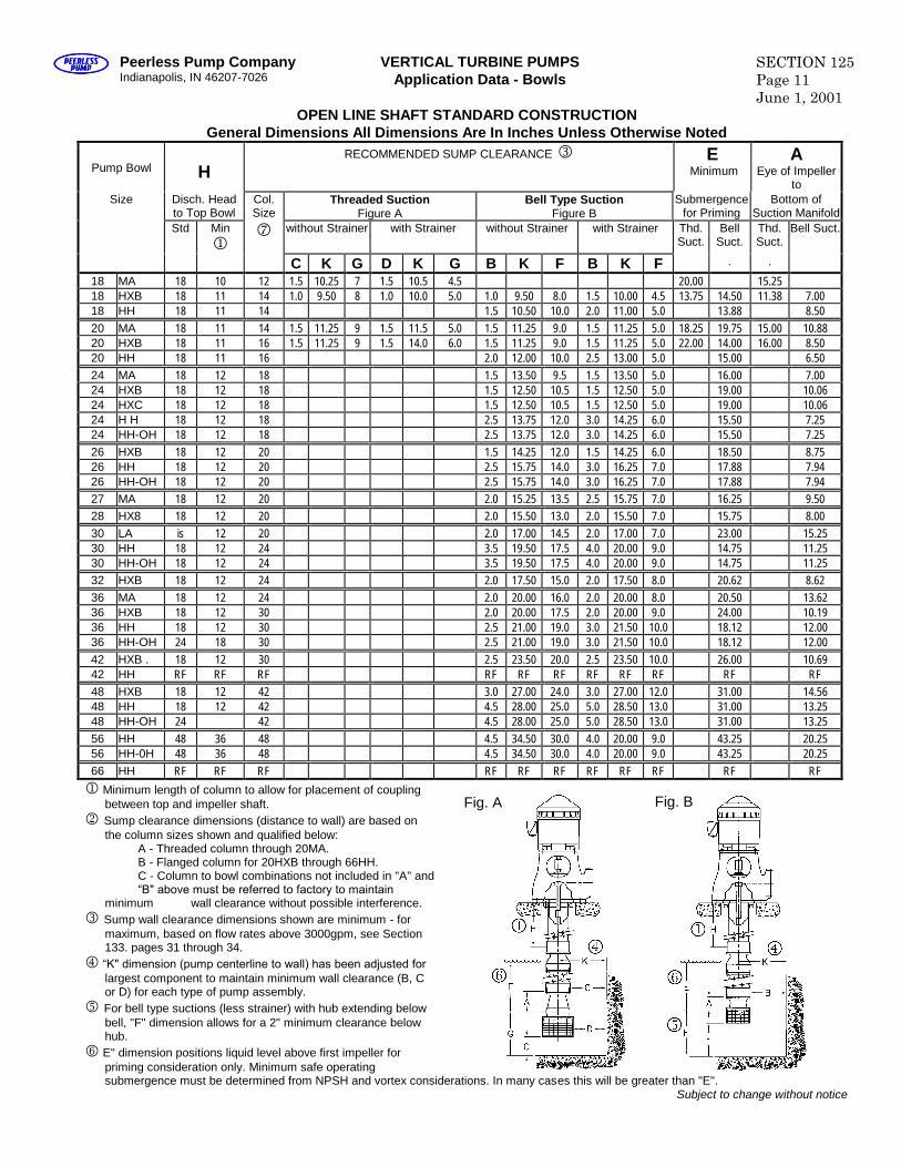
Peerless Pump CompanyIndianapolis, IN 46207-7026
VERTICAL TURBINE PUMPSApplication Data - Bowls
SECTION 125Page 11June 1, 2001
OPEN LINE SHAFT STANDARD CONSTRUCTIONGeneral Dimensions All Dimensions Are In Inches Unless Otherwise Noted
Pump Bowl HRECOMMENDED SUMP CLEARANCE E
MinimumA
Eye of Impellerto
Size Disch. Headto Top Bowl
Col.Size
Threaded SuctionFigure A
Bell Type SuctionFigure B
Submergencefor Priming
Bottom ofSuction Manifold
Std Min
without Strainer with Strainer without Strainer with Strainer Thd.Suct.
BellSuct.
Thd.Suct.
Bell Suct.
C K G D K G B K F B K F . .
18 MA 18 10 12 1.5 10.25 7 1.5 10.5 4.5 20.00 15.2518 HXB 18 11 14 1.0 9.50 8 1.0 10.0 5.0 1.0 9.50 8.0 1.5 10.00 4.5 13.75 14.50 11.38 7.0018 HH 18 11 14 1.5 10.50 10.0 2.0 11.00 5.0 13.88 8.5020 MA 18 11 14 1.5 11.25 9 1.5 11.5 5.0 1.5 11.25 9.0 1.5 11.25 5.0 18.25 19.75 15.00 10.8820 HXB 18 11 16 1.5 11.25 9 1.5 14.0 6.0 1.5 11.25 9.0 1.5 11.25 5.0 22.00 14.00 16.00 8.5020 HH 18 11 16 2.0 12.00 10.0 2.5 13.00 5.0 15.00 6.5024 MA 18 12 18 1.5 13.50 9.5 1.5 13.50 5.0 16.00 7.0024 HXB 18 12 18 1.5 12.50 10.5 1.5 12.50 5.0 19.00 10.0624 HXC 18 12 18 1.5 12.50 10.5 1.5 12.50 5.0 19.00 10.0624 H H 18 12 18 2.5 13.75 12.0 3.0 14.25 6.0 15.50 7.2524 HH-OH 18 12 18 2.5 13.75 12.0 3.0 14.25 6.0 15.50 7.2526 HXB 18 12 20 1.5 14.25 12.0 1.5 14.25 6.0 18.50 8.7526 HH 18 12 20 2.5 15.75 14.0 3.0 16.25 7.0 17.88 7.9426 HH-OH 18 12 20 2.5 15.75 14.0 3.0 16.25 7.0 17.88 7.9427 MA 18 12 20 2.0 15.25 13.5 2.5 15.75 7.0 16.25 9.5028 HX8 18 12 20 2.0 15.50 13.0 2.0 15.50 7.0 15.75 8.0030 LA is 12 20 2.0 17.00 14.5 2.0 17.00 7.0 23.00 15.2530 HH 18 12 24 3.5 19.50 17.5 4.0 20.00 9.0 14.75 11.2530 HH-OH 18 12 24 3.5 19.50 17.5 4.0 20.00 9.0 14.75 11.2532 HXB 18 12 24 2.0 17.50 15.0 2.0 17.50 8.0 20.62 8.6236 MA 18 12 24 2.0 20.00 16.0 2.0 20.00 8.0 20.50 13.6236 HXB 18 12 30 2.0 20.00 17.5 2.0 20.00 9.0 24.00 10.1936 HH 18 12 30 2.5 21.00 19.0 3.0 21.50 10.0 18.12 12.0036 HH-OH 24 18 30 2.5 21.00 19.0 3.0 21.50 10.0 18.12 12.0042 HXB . 18 12 30 2.5 23.50 20.0 2.5 23.50 10.0 26.00 10.6942 HH RF RF RF RF RF RF RF RF RF RF RF48 HXB 18 12 42 3.0 27.00 24.0 3.0 27.00 12.0 31.00 14.5648 HH 18 12 42 4.5 28.00 25.0 5.0 28.50 13.0 31.00 13.2548 HH-OH 24 42 4.5 28.00 25.0 5.0 28.50 13.0 31.00 13.2556 HH 48 36 48 4.5 34.50 30.0 4.0 20.00 9.0 43.25 20.2556 HH-0H 48 36 48 4.5 34.50 30.0 4.0 20.00 9.0 43.25 20.2566 HH RF RF RF RF RF RF RF RF RF RF RF
Minimum length of column to allow for placement of couplingbetween top and impeller shaft.
Sump clearance dimensions (distance to wall) are based onthe column sizes shown and qualified below:
A - Threaded column through 20MA.B - Flanged column for 20HXB through 66HH.C - Column to bowl combinations not included in "A" and“B" above must be referred to factory to maintain
minimum wall clearance without possible interference. Sump wall clearance dimensions shown are minimum - for
maximum, based on flow rates above 3000gpm, see Section133. pages 31 through 34.
“K" dimension (pump centerline to wall) has been adjusted for largest component to maintain minimum wall clearance (B, Cor D) for each type of pump assembly.
For bell type suctions (less strainer) with hub extending belowbell, "F" dimension allows for a 2" minimum clearance belowhub.
E" dimension positions liquid level above first impeller forpriming consideration only. Minimum safe operatingsubmergence must be determined from NPSH and vortex considerations. In many cases this will be greater than "E".
Subject to change without notice
Fig. A Fig. B
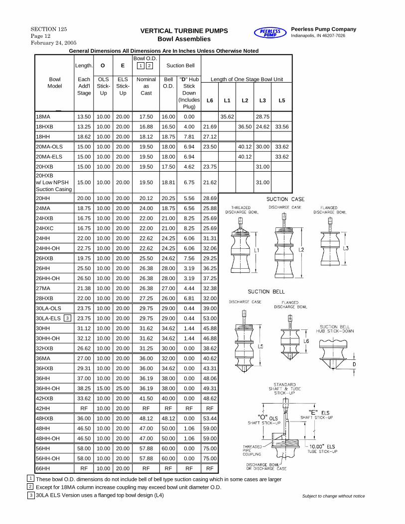
General Dimensions All Dimensions Are In Inches Unless Otherwise Noted
Length. O EBowl O.D.
Suction Bell
Bowl Each OLS ELS Nominal Bell "D" Hub Length of One Stage Bowl UnitModel Add'l Stick- Stick- as O.D. Stick
Stage Up Up Cast Down(Includes
Plug)L6 L1 L2 L3 L5
18MA 13.50 10.00 20.00 17.50 16.00 0.00 35.62 28.75
18HXB 13.25 10.00 20.00 16.88 16.50 4.00 21.69 36.50 24.62 33.56
18HH 18.62 10.00 20.00 18.12 18.75 7.81 27.12
20MA-OLS 15.00 10.00 20.00 19.50 18.00 6.94 23.50 40.12 30.00 33.62
20MA-ELS 15.00 10.00 20.00 19.50 18.00 6.94 40.12 33.62
20HXB 15.00 10.00 20.00 19.50 17.50 4.62 23.75 31.00
20HXBw/ Low NPSHSuction Casing
15.00 10.00 20.00 19.50 18.81 6.75 21.62 31.00
20HH 20.00 10.00 20.00 20.12 20.25 5.56 28.69
24MA 18.75 10.00 20.00 24.00 18.75 6.56 25.88
24HXB 16.75 10.00 20.00 22.00 21.00 8.25 25.69
24HXC 16.75 10.00 20.00 22.00 21.00 8.25 25.69
24HH 22.00 10.00 20.00 22.62 24.25 6.06 31.31
24HH-OH 22.75 10.00 20.00 22.62 24.25 6.06 32.06
26HXB 19.75 10.00 20.00 25.50 24.62 7.56 29.25
26HH 25.50 10.00 20.00 26.38 28.00 3.19 36.25
26HH-OH 26.50 10.00 20.00 26.38 28.00 3.19 37.25
27MA 21.38 10.00 20.00 26.38 27.00 4.44 32.38
28HXB 22.00 10.00 20.00 27.25 26.00 6.81 32.00
30LA-OLS 23.75 10.00 20.00 29.75 29.00 0.44 39.00
30LA-ELS 23.75 10.00 20.00 29.75 29.00 0.44 53.00
30HH 31.12 10.00 20.00 31.62 34.62 1.44 45.88
30HH-OH 32.12 10.00 20.00 31.62 34.62 1.44 46.88
32HXB 26.62 10.00 20.00 31.25 30.00 0.00 38.62
36MA 27.00 10.00 20.00 36.00 32.00 0.00 40.62
36HXB 29.31 10.00 20.00 36.00 34.62 0.00 43.31
36HH 37.00 10.00 20.00 36.19 38.00 0.00 48.06
36HH-OH 38.25 15.00 25.00 36.19 38.00 0.00 49.31
42HXB 33.62 10.00 20.00 41.50 40.00 0.00 48.62
42HH RF 10.00 20.00 RF RF RF RF
48HXB 36.00 10.00 20.00 48.12 48.12 0.00 53.44
48HH 46.50 10.00 20.00 47.00 50.00 1.06 59.00
48HH-OH 46.50 10.00 20.00 47.00 50.00 1.06 59.00
56HH 58.00 10.00 20.00 57.88 60.00 0.00 75.00
56HH-OH 58.00 10.00 20.00 57.88 60.00 0.00 75.00
66HH RF 10.00 20.00 RF RF RF RF
These bowl O.D. dimensions do not include bell of bell type suction casing which in some cases are largerExcept for 18MA column increase coupling may exceed bowl unit diameter O.D.30LA ELS Version uses a flanged top bowl design (L4) Subject to change without notice
21
1
2
Peerless Pump CompanyIndianapolis, IN 46207-7026
VERTICAL TURBINE PUMPSBowl Assemblies
SECTION 125Page 12February 24, 2005
3
3
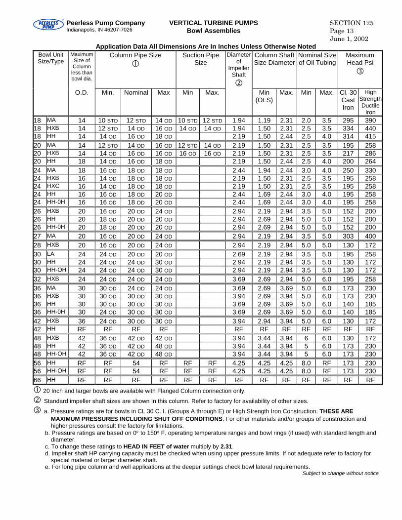
Peerless Pump CompanyIndianapolis, IN 46207-7026
VERTICAL TURBINE PUMPSBowl Assemblies
SECTION 125Page 13June 1, 2002
Application Data All Dimensions Are In Inches Unless Otherwise NotedBowl UnitSize/Type
MaximumSize ofColumn
less thanbowl dia.
Column Pipe Size
Suction PipeSize
Diameterof
ImpellerShaft
Column ShaftSize Diameter
Nominal Sizeof Oil Tubing
MaximumHead Psi
O.D. Min. Nominal Max Min Max. Min(OLS)
Max. Min Max. Cl. 30CastIron
HighStrengthDuctile
Iron18 MA 14 10 STD 12 STD 14 OD 10 STD 12 STD 1.94 1.19 2.31 2.0 3.5 295 39018 HXB 14 12 STD 14 OD 16 OD 14 OD 14 OD 1.94 1.50 2.31 2.5 3.5 334 44018 HH 14 14 OD 16 OD 18 OD 2.19 1.50 2.44 2.5 4.0 314 41520 MA 14 12 STD 14 OD 16 OD 12 STD 14 OD 2.19 1.50 2.31 2.5 3.5 195 25820 HXB 14 14 OD 16 OD 16 OD 16 OD 16 OD 2.19 1.50 2.31 2.5 3.5 217 28620 HH 18 14 OD 16 OD 18 OD 2.19 1.50 2.44 2.5 4.0 200 26424 MA 18 16 OD 18 OD 18 OD 2.44 1.94 2.44 3.0 4.0 250 33024 HXB 16 14 OD 18 OD 18 OD 2.19 1.50 2.31 2.5 3.5 195 25824 HXC 16 14 OD 18 OD 18 OD 2.19 1.50 2.31 2.5 3.5 195 25824 HH 16 16 OD 18 OD 20 OD 2.44 1.69 2.44 3.0 4.0 195 25824 HH-0H 16 16 OD 18 OD 20 OD 2.44 1.69 2.44 3.0 4.0 195 25826 HXB 20 16 OD 20 OD 24 OD 2.94 2.19 2.94 3.5 5.0 152 20026 HH 20 18 OD 20 OD 20 OD 2.94 2.69 2.94 5.0 5.0 152 20026 HH-0H 20 18 OD 20 OD 20 OD 2.94 2.69 2.94 5.0 5.0 152 20027 MA 20 16 OD 20 OD 24 OD 2.94 2.19 2.94 3.5 5.0 303 40028 HXB 20 16 OD 20 OD 24 OD 2.94 2.19 2.94 5.0 5.0 130 17230 LA 24 24 OD 20 OD 20 OD 2.69 2.19 2.94 3.5 5.0 195 25830 HH 24 24 OD 24 OD 30 OD 2.94 2.19 2.94 3.5 5.0 130 17230 HH-OH 24 24 OD 24 OD 30 OD 2.94 2.19 2.94 3.5 5.0 130 17232 HXB 24 24 OD 24 OD 24 OD 3.69 2.69 2.94 5.0 6.0 195 25836 MA 30 30 OD 24 OD 24 OD 3.69 2.69 3.69 5.0 6.0 173 23036 HXB 30 30 OD 30 OD 30 OD 3.94 2.69 3.94 5.0 6.0 173 23036 HH 30 30 OD 30 OD 30 OD 3.69 2.69 3.69 5.0 6.0 140 18536 HH-0H 30 24 OD 30 OD 30 OD 3.69 2.69 3.69 5.0 6.0 140 18542 HXB 36 24 OD 30 OD 30 OD 3.94 2.94 3.94 5.0 6.0 130 17242 HH RF RF RF RF RF RF RF RF RF RF RF48 HXB 42 36 OD 42 OD 42 OD 3.94 3.44 3.94 6 6.0 130 17248 HH 42 36 OD 42 OD 48 OD 3.94 3.44 3.94 5 6.0 173 23048 HH-OH 42 36 OD 42 OD 48 OD 3.94 3.44 3.94 5 6.0 173 23056 HH RF RF 54 RF RF RF 4.25 4.25 4.25 8.0 RF 173 23056 HH-OH RF RF 54 RF RF RF 4.25 4.25 4.25 8.0 RF 173 23066 HH RF RF RF RF RF RF RF RF RF RF RF RF RF
20 Inch and larger bowls are available with Flanged Column connection only.
Standard impeller shaft sizes are shown In this column. Refer to factory for availability of other sizes.
a. Pressure ratings are for bowls in CL 30 C. I. (Groups A through E) or High Strength Iron Construction. THESE AREMAXIMUM PRESSURES INCLUDING SHUT OFF CONDITIONS. For other materials and/or groups of construction andhigher pressures consult the factory for limitations.
b. Pressure ratings are based on 0to 150F. operating temperature ranges and bowl rings (if used) with standard length anddiameter.
c. To change these ratings to HEAD IN FEET of water multiply by 2.31.d. Impeller shaft HP carrying capacity must be checked when using upper pressure limits. If not adequate refer to factory for
special material or larger diameter shaft.e. For long pipe column and well applications at the deeper settings check bowl lateral requirements.
Subject to change without notice
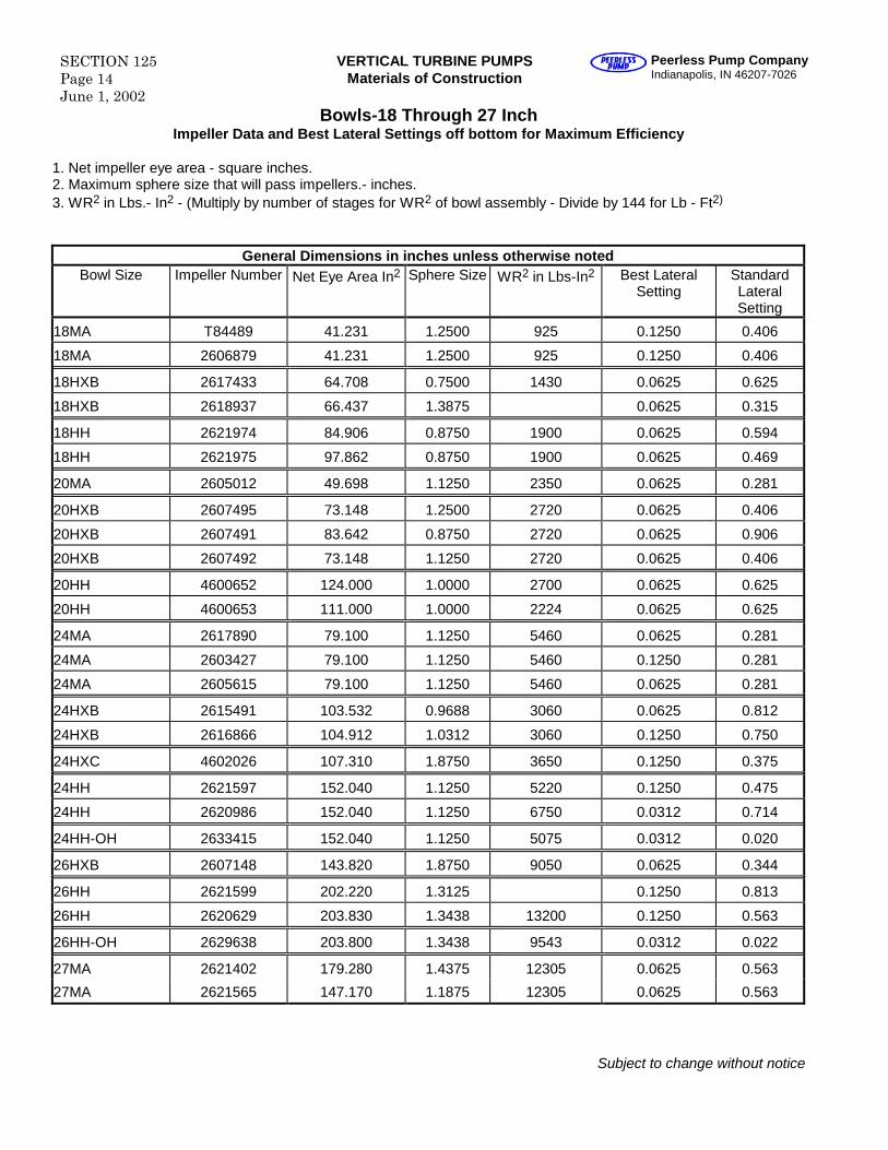
SECTION 125Page 14June 1, 2002
VERTICAL TURBINE PUMPSMaterials of Construction
Peerless Pump CompanyIndianapolis, IN 46207-7026
Bowls-18 Through 27 InchImpeller Data and Best Lateral Settings off bottom for Maximum Efficiency
1. Net impeller eye area - square inches.2. Maximum sphere size that will pass impellers.- inches.3. WR2 in Lbs.- In2 - (Multiply by number of stages for WR2 of bowl assembly - Divide by 144 for Lb - Ft2)
General Dimensions in inches unless otherwise notedBowl Size Impeller Number Net Eye Area In2 Sphere Size WR2 in Lbs-In2 Best Lateral
SettingStandardLateralSetting
18MA T84489 41.231 1.2500 925 0.1250 0.406
18MA 2606879 41.231 1.2500 925 0.1250 0.406
18HXB 2617433 64.708 0.7500 1430 0.0625 0.625
18HXB 2618937 66.437 1.3875 0.0625 0.315
18HH 2621974 84.906 0.8750 1900 0.0625 0.594
18HH 2621975 97.862 0.8750 1900 0.0625 0.469
20MA 2605012 49.698 1.1250 2350 0.0625 0.281
20HXB 2607495 73.148 1.2500 2720 0.0625 0.406
20HXB 2607491 83.642 0.8750 2720 0.0625 0.906
20HXB 2607492 73.148 1.1250 2720 0.0625 0.406
20HH 4600652 124.000 1.0000 2700 0.0625 0.625
20HH 4600653 111.000 1.0000 2224 0.0625 0.625
24MA 2617890 79.100 1.1250 5460 0.0625 0.281
24MA 2603427 79.100 1.1250 5460 0.1250 0.281
24MA 2605615 79.100 1.1250 5460 0.0625 0.281
24HXB 2615491 103.532 0.9688 3060 0.0625 0.812
24HXB 2616866 104.912 1.0312 3060 0.1250 0.750
24HXC 4602026 107.310 1.8750 3650 0.1250 0.375
24HH 2621597 152.040 1.1250 5220 0.1250 0.475
24HH 2620986 152.040 1.1250 6750 0.0312 0.714
24HH-OH 2633415 152.040 1.1250 5075 0.0312 0.020
26HXB 2607148 143.820 1.8750 9050 0.0625 0.344
26HH 2621599 202.220 1.3125 0.1250 0.813
26HH 2620629 203.830 1.3438 13200 0.1250 0.563
26HH-OH 2629638 203.800 1.3438 9543 0.0312 0.022
27MA 2621402 179.280 1.4375 12305 0.0625 0.563
27MA 2621565 147.170 1.1875 12305 0.0625 0.563
Subject to change without notice
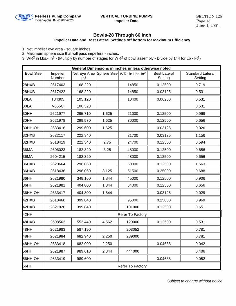
Peerless Pump CompanyIndianapolis, IN 46207-7026
VERTICAL TURBINE PUMPSImpeller Data
SECTION 125Page 15June 1, 2001
Bowls-28 Through 66 InchImpeller Data and Best Lateral Settings off bottom for Maximum Efficiency
1. Net impeller eye area - square inches.2. Maximum sphere size that will pass impellers.- inches.3. WR2 in Lbs.- In2 - (Multiply by number of stages for WR2 of bowl assembly - Divide by 144 for Lb - Ft2)
General Dimensions in inches unless otherwise notedBowl Size Impeller
NumberNet Eye Area
In2Sphere Size WR2 in Lbs-In2 Best Lateral
SettingStandard Lateral
Setting
28HXB 2617403 168.220 14850 0.12500 0.719
28HXB 2617422 168.220 14850 0.03125 0.531
30LA T84305 105.120 10400 0.06250 0.531
30LA V655C 106.323 0.531
30HH 2621977 295.710 1.625 21000 0.12500 0.969
30HH 2621978 299.570 1.625 30000 0.12500 0.656
30HH-OH 2633416 299.600 1.625 0.03125 0.026
32HXB 2622117 222.340 21700 0.03125 1.156
32HXB 2618419 222.340 2.75 24700 0.12500 0.594
36MA 2606023 182.320 3.25 48000 0.12500 0.656
36MA 2604215 182.320 48000 0.12500 0.656
36HXB 2620664 296.060 50000 0.12500 1.563
36HXB 2618436 296.060 3.125 51500 0.25000 0.688
36HH 2621980 348.160 1.844 45000 0.12500 0.906
36HH 2621981 404.800 1.844 64000 0.12500 0.656
36HH-OH 2633417 404.800 1.844 0.03125 0.029
42HXB 2618460 399.840 95000 0.25000 0.969
42HXB 2621920 399.840 101000 0.12500 0.651
42HH Refer To Factory
48HXB 2608562 553.440 4.562 129000 0.12500 0.531
48HH 2621983 587.190 203052 0.781
48HH 2621984 682.940 2.250 289000 0.781
48HH-OH 2633418 682.900 2.250 0.04688 0.042
56HH 2621987 989.610 2.844 444000 0.406
56HH-OH 2633419 989.600 0.04688 0.052
66HH Refer To Factory
Subject to change without notice
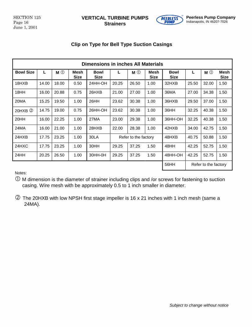
SECTION 125Page 16June 1, 2001
VERTICAL TURBINE PUMPSStrainers
Peerless Pump CompanyIndianapolis, IN 46207-7026
Clip on Type for Bell Type Suction Casings
Dimensions in inches All Materials
Bowl Size L M MeshSize
BowlSize
L M MeshSize
BowlSize
L M MeshSize
18HXB 14.00 18.00 0.50 24HH-OH 20.25 26.50 1.00 32HXB 25.50 32.00 1.50
18HH 16.00 20.88 0.75 26HXB 21.00 27.00 1.00 36MA 27.00 34.38 1.50
20MA 15.25 19.50 1.00 26HH 23.62 30.38 1.00 36HXB 29.50 37.00 1.50
20HXB 14.75 19.00 0.75 26HH-OH 23.62 30.38 1.00 36HH 32.25 40.38 1.50
20HH 16.00 22.25 1.00 27MA 23.00 29.38 1.00 36HH-OH 32.25 40.38 1.50
24MA 16.00 21.00 1.00 28HXB 22.00 28.38 1.00 42HXB 34.00 42.75 1.50
24HXB 17.75 23.25 1.00 30LA Refer to the factory 48HXB 40.75 50.88 1.50
24HXC 17.75 23.25 1.00 30HH 29.25 37.25 1.50 48HH 42.25 52.75 1.50
24HH 20.25 26.50 1.00 30HH-0H 29.25 37.25 1.50 48HH-OH 42.25 52.75 1.50
56HH Refer to the factory
Notes:
M dimension is the diameter of strainer including clips and /or screws for fastening to suctioncasing. Wire mesh with be approximately 0.5 to 1 inch smaller in diameter.
The 20HXB with low NPSH first stage impeller is 16 x 21 inches with 1 inch mesh (same a24MA).
Subject to change without notice
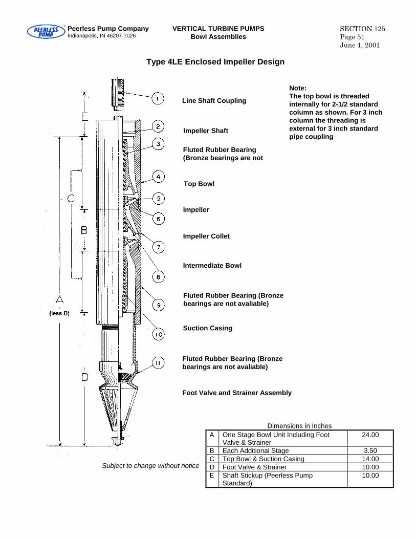
Peerless Pump CompanyIndianapolis, IN 46207-7026
VERTICAL TURBINE PUMPSBowl Assemblies
SECTION 125Page 51June 1, 2001
Type 4LE Enclosed Impeller Design
Subject to change without notice
Dimensions in InchesA One Stage Bowl Unit Including Foot
Valve & Strainer24.00
B Each Additional Stage 3.50C Top Bowl & Suction Casing 14.00D Foot Valve & Strainer 10.00E Shaft Stickup (Peerless Pump
Standard)10.00
Note:The top bowl is threadedinternally for 2-1/2 standardcolumn as shown. For 3 inchcolumn the threading isexternal for 3 inch standardpipe coupling
Line Shaft Coupling
Impeller Shaft
Fluted Rubber Bearing(Bronze bearings are not
Top Bowl
Impeller
Impeller Collet
Intermediate Bowl
Fluted Rubber Bearing (Bronzebearings are not avaliable)
Suction Casing
Fluted Rubber Bearing (Bronzebearings are not avaliable)
Foot Valve and Strainer Assembly
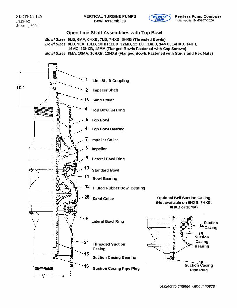
SECTION 125Page 52June 1, 2001
VERTICAL TURBINE PUMPSBowl Assemblies
Peerless Pump CompanyIndianapolis, IN 46207-7026
Open Line Shaft Assemblies with Top BowlBowl Sizes 6LB, 6MA, 6HXB, 7LB, 7HXB, 8HXB (Threaded Bowls)Bowl Sizes 8LB, 9LA, 10LB, 10HH 12LD, 12MB, 12HXH, 14LD, 14MC, 14HXB, 14HH,
16MC, 16HXB, 18MA (Flanged Bowls Fastened with Cap Screws)Bowl Sizes 8MA, 10MA, 10HXB, 12HXB (Flanged Bowls Fastened with Studs and Hex Nuts)
Subject to change without notice
Line Shaft Coupling
Impeller Shaft
Sand Collar
Top Bowl
Impeller
Impeller Collet
Standard Bowl
Fluted Rubber Bowl Bearing
Optional Bell Suction Casing(Not available on 6HXB, 7HXB,
8HXB or 18MA)
Threaded SuctionCasing
Lateral Bowl Ring
Top Bowl Bearing
Bowl Bearing
Sand Collar
Lateral Bowl Ring
Suction Casing Bearing
Suction Casing Pipe PlugSuction Casing
Pipe Plug
SuctionCasingBearing
SuctionCasing
Top Bowl Bearing
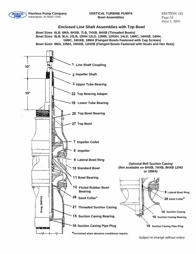
Peerless Pump CompanyIndianapolis, IN 46207-7026
VERTICAL TURBINE PUMPSBowl Assemblies
SECTION 125Page 53June 1, 2001
Enclosed Line Shaft Assemblies with Top BowlBowl Sizes 6LB, 6MA, 6HXB, 7LB, 7HXB, 8HXB (Threaded Bowls)Bowl Sizes 8LB, 9LA, 10LB, 10HH 12LD, 12MB, 12HXH, 14LD, 14MC, 14HXB, 14HH,
16MC, 16HXB, 18MA (Flanged Bowls Fastened with Cap Screws)Bowl Sizes 8MA, 10MA, 10HXB, 12HXB (Flanged Bowls Fastened with Studs and Hex Nuts)
Subject to change without notice
Line Shaft Coupling
Impeller Shaft
Upper Tube Bearing
Top Bowl
Impeller
Impeller Collet
Standard Bowl
Fluted Rubber BowlBearing
Optional Bell Suction Casing(Not available on 6HXB, 7HXB, 8HXB 12HD
or 18MA)
Threaded Suction Casing
Top Bearing Adaper
Top Bowl Bearing
Bowl Bearing
Sand Collar*
Lateral Bowl Ring
Suction Casing Bearing
Suction Casing Pipe Plug Suction Casing Pipe Plug
Suction Casing
Lower Tube Bearing
Suction Casing Bearing
Lateral Bowl Ring
Sand Collar*
*Furnished when abrasive conditions require.
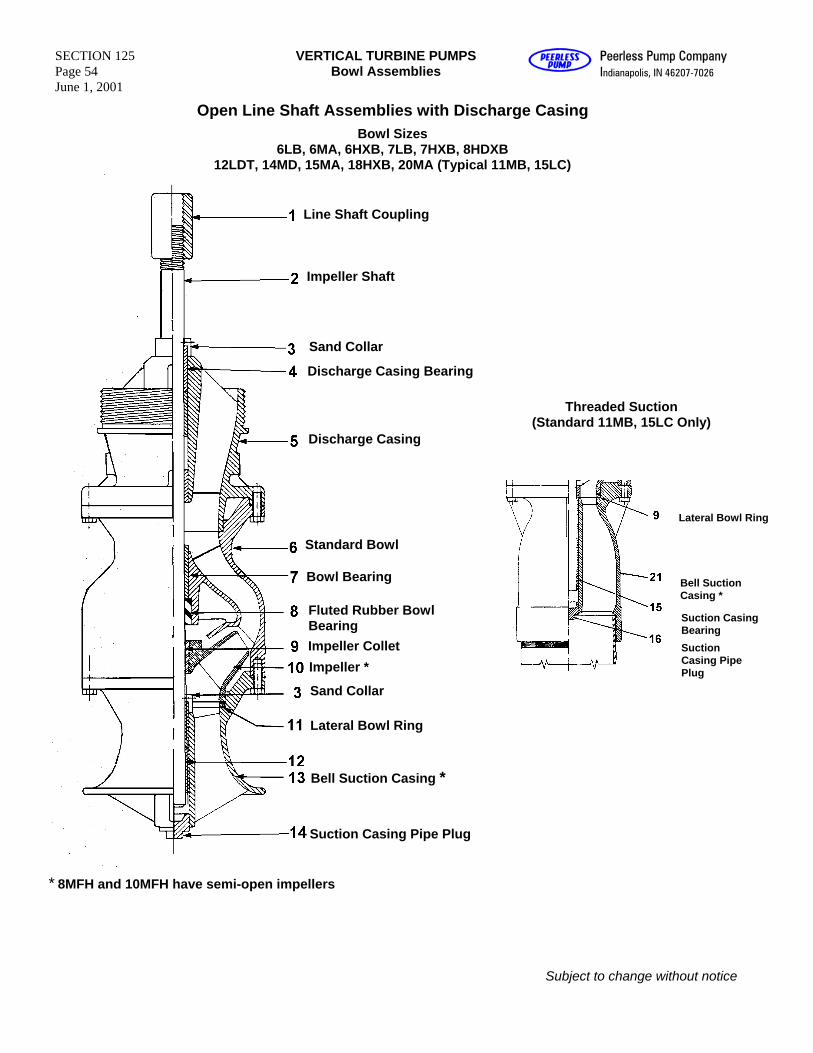
SECTION 125 Page 54 June 1, 2001
VERTICAL TURBINE PUMPS Bowl Assemblies
Peerless Pump Company Indianapolis, IN 46207-7026
Open Line Shaft Assemblies with Discharge Casing
Bowl Sizes 6LB, 6MA, 6HXB, 7LB, 7HXB, 8HDXB
12LDT, 14MD, 15MA, 18HXB, 20MA (Typical 11MB, 15LC)
Line Shaft Coupling
Impeller Shaft
Sand Collar
Discharge Casing Bearing
Threaded Suction (Standard 11MB, 15LC Only)
Discharge Casing
Lateral Bowl Ring
Standard Bowl
Bowl Bearing Bell Suction Casing *
Fluted Rubber Bowl Bearing Suction Casing
Bearing Impeller Collet Suction
Casing Pipe Plug Impeller *
Sand Collar
Lateral Bowl Ring
Bell Suction Casing *
Suction Casing Pipe Plug
* 8MFH and 10MFH have semi-open impellers
Subject to change without notice
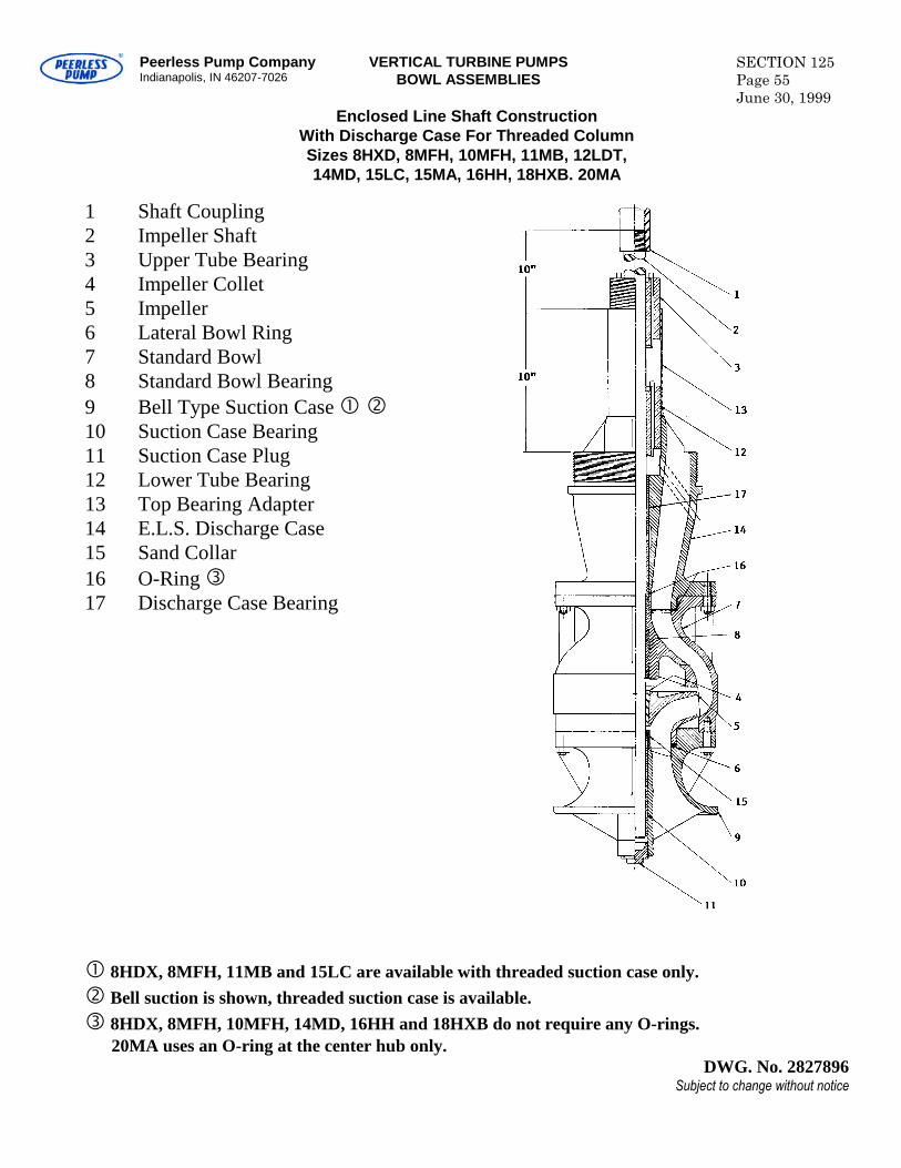
Peerless Pump CompanyIndianapolis, IN 46207-7026
VERTICAL TURBINE PUMPSBOWL ASSEMBLIES
SECTION 125Page 55June 30, 1999
Enclosed Line Shaft ConstructionWith Discharge Case For Threaded ColumnSizes 8HXD, 8MFH, 10MFH, 11MB, 12LDT,14MD, 15LC, 15MA, 16HH, 18HXB. 20MA
1 Shaft Coupling2 Impeller Shaft3 Upper Tube Bearing4 Impeller Collet5 Impeller6 Lateral Bowl Ring7 Standard Bowl8 Standard Bowl Bearing9 Bell Type Suction Case10 Suction Case Bearing11 Suction Case Plug12 Lower Tube Bearing13 Top Bearing Adapter14 E.L.S. Discharge Case15 Sand Collar16 O-Ring17 Discharge Case Bearing
8HDX, 8MFH, 11MB and 15LC are available with threaded suction case only.Bell suction is shown, threaded suction case is available.8HDX, 8MFH, 10MFH, 14MD, 16HH and 18HXB do not require any O-rings.
20MA uses an O-ring at the center hub only.DWG. No. 2827896
Subject to change without notice

Blank
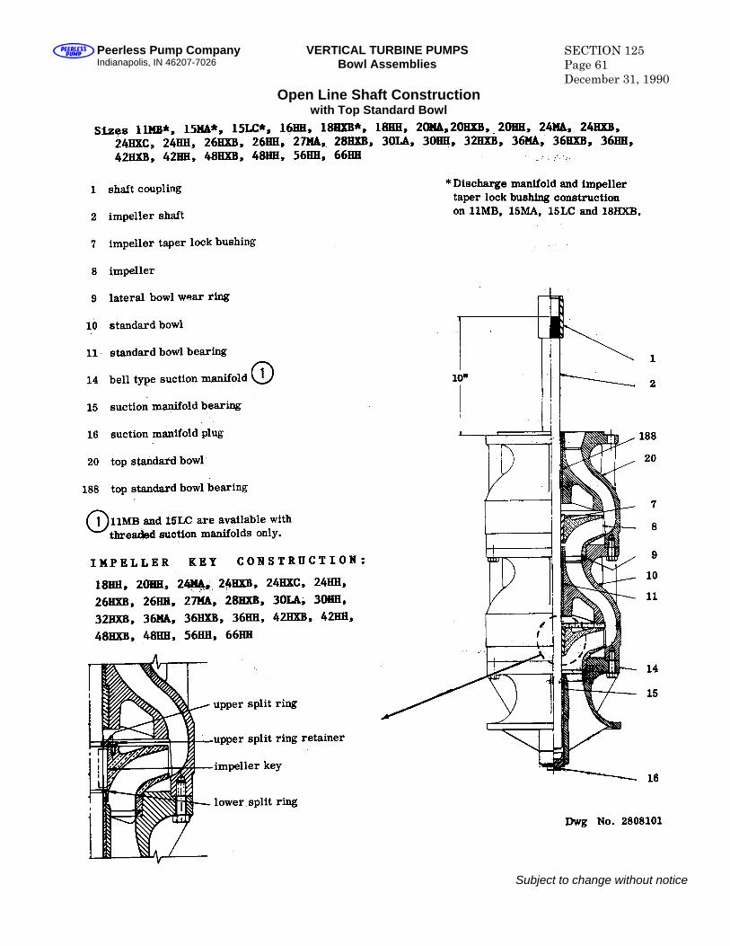
Peerless Pump Company Indianapolis, IN 46207-7026
VERTICAL TURBINE PUMPS Bowl Assemblies
SECTION 125 Page 61 December 31, 1990
Open Line Shaft Construction with Top Standard Bowl
Subject to change without notice
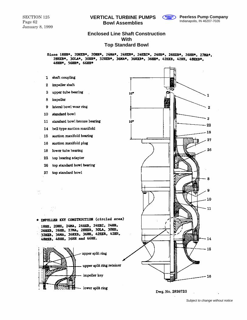
SECTION 125 Page 62 January 8, 1999
VERTICAL TURBINE PUMPS Bowl Assemblies
Peerless Pump Company Indianapolis, IN 46207-7026
Enclosed Line Shaft Construction With
Top Standard Bowl
Subject to change without notice
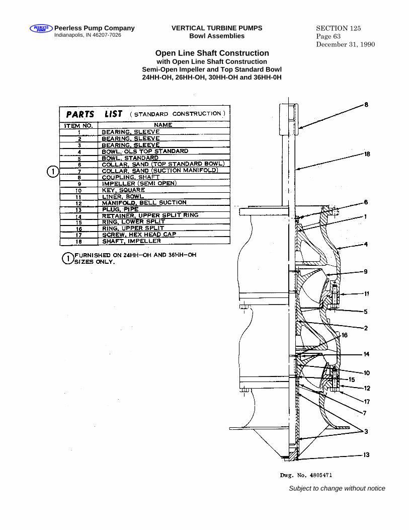
Peerless Pump Company Indianapolis, IN 46207-7026
VERTICAL TURBINE PUMPS Bowl Assemblies
SECTION 125 Page 63 December 31, 1990
Open Line Shaft Construction with Open Line Shaft Construction
Semi-Open Impeller and Top Standard Bowl 24HH-OH, 26HH-OH, 30HH-OH and 36HH-0H
Subject to change without notice
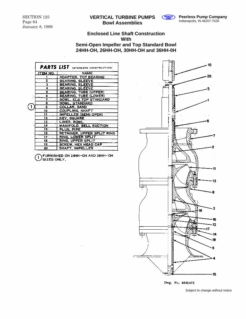
SECTION 125 Page 64 January 8, 1999
VERTICAL TURBINE PUMPS Bowl Assemblies
Peerless Pump Company Indianapolis, IN 46207-7026
Enclosed Line Shaft Construction With
Semi-Open Impeller and Top Standard Bowl 24HH-OH, 26HH-OH, 30HH-OH and 36HH-0H
Subject to change without notice
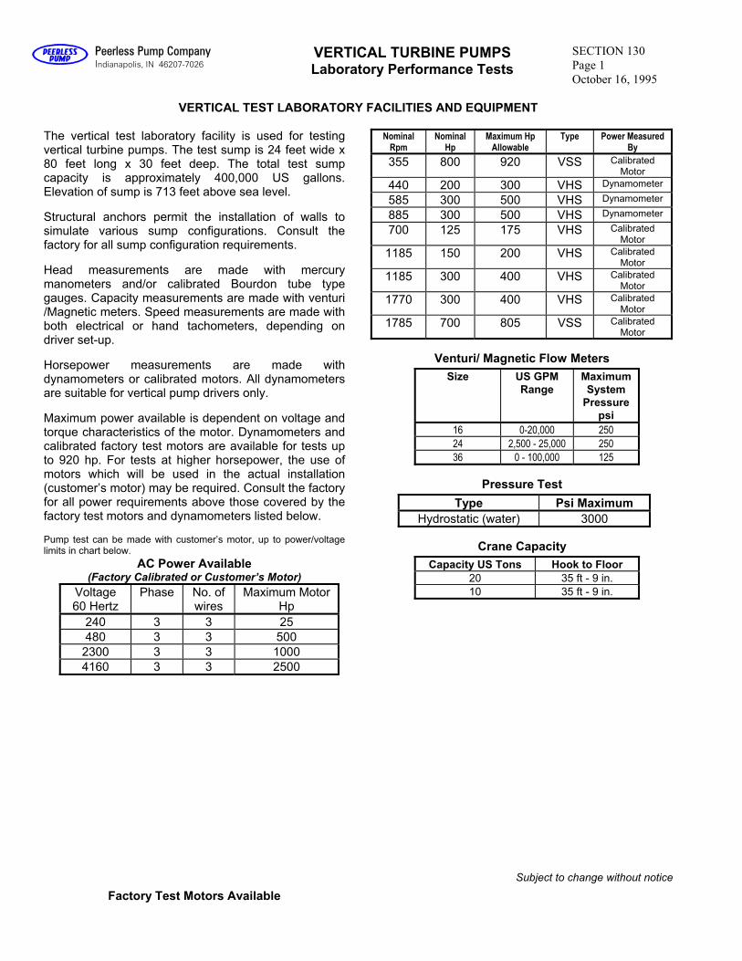
Peerless Pump Company Indianapolis, IN 46207-7026
VERTICAL TURBINE PUMPS Laboratory Performance Tests
SECTION 130
Page 1
October 16, 1995
VERTICAL TEST LABORATORY FACILITIES AND EQUIPMENT
The vertical test laboratory facility is used for testing vertical turbine pumps. The test sump is 24 feet wide x 80 feet long x 30 feet deep. The total test sump capacity is approximately 400,000 US gallons. Elevation of sump is 713 feet above sea level.
Structural anchors permit the installation of walls to simulate various sump configurations. Consult thefactory for all sump configuration requirements.
Head measurements are made with mercurymanometers and/or calibrated Bourdon tube type gauges. Capacity measurements are made with venturi /Magnetic meters. Speed measurements are made with both electrical or hand tachometers, depending ondriver set-up.
Horsepower measurements are made withdynamometers or calibrated motors. All dynamometersare suitable for vertical pump drivers only.
Maximum power available is dependent on voltage and torque characteristics of the motor. Dynamometers and calibrated factory test motors are available for tests up to 920 hp. For tests at higher horsepower, the use of motors which will be used in the actual installation(customer’s motor) may be required. Consult the factory for all power requirements above those covered by thefactory test motors and dynamometers listed below.
Pump test can be made with customer’s motor, up to power/voltagelimits in chart below.
AC Power Available(Factory Calibrated or Customer’s Motor)
Voltage60 Hertz
Phase No. ofwires
Maximum Motor Hp
240 3 3 25480 3 3 500
2300 3 3 10004160 3 3 2500
Factory Test Motors Available
NominalRpm
NominalHp
Maximum Hp Allowable
Type Power MeasuredBy
355 800 920 VSS CalibratedMotor
440 200 300 VHS Dynamometer
585 300 500 VHS Dynamometer
885 300 500 VHS Dynamometer
700 125 175 VHS CalibratedMotor
1185 150 200 VHS CalibratedMotor
1185 300 400 VHS CalibratedMotor
1770 300 400 VHS CalibratedMotor
1785 700 805 VSS CalibratedMotor
Venturi/ Magnetic Flow Meters
Size US GPMRange
MaximumSystem
Pressurepsi
16 0-20,000 250
24 2,500 - 25,000 250
36 0 - 100,000 125
Pressure Test
Type Psi Maximum
Hydrostatic (water) 3000
Crane Capacity
Capacity US Tons Hook to Floor
20 35 ft - 9 in. 10 35 ft - 9 in.
Subject to change without notice
Peerless Pump CompanyHandbook of Engineering Data
Brochure EM77
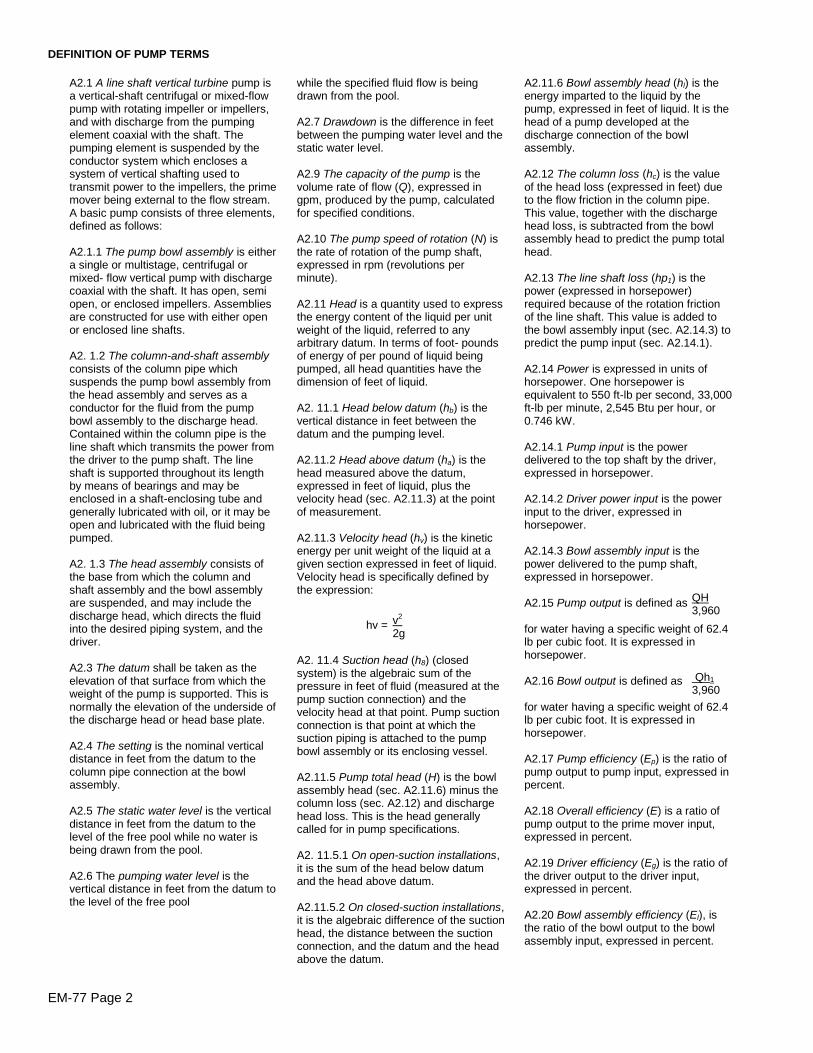
EM-77 Page 2
DEFINITION OF PUMP TERMS
while the specified fluid flow is beingdrawn from the pool.
A2.7 Drawdown is the difference in feetbetween the pumping water level and thestatic water level.
A2.9 The capacity of the pump is thevolume rate of flow (Q), expressed ingpm, produced by the pump, calculatedfor specified conditions.
A2.10 The pump speed of rotation (N) isthe rate of rotation of the pump shaft,expressed in rpm (revolutions perminute).
A2.11 Head is a quantity used to expressthe energy content of the liquid per unitweight of the liquid, referred to anyarbitrary datum. In terms of foot- poundsof energy of per pound of liquid beingpumped, all head quantities have thedimension of feet of liquid.
A2. 11.1 Head below datum (hb) is thevertical distance in feet between thedatum and the pumping level.
A2.11.2 Head above datum (ha) is thehead measured above the datum,expressed in feet of liquid, plus thevelocity head (sec. A2.11.3) at the pointof measurement.
A2.11.3 Velocity head (hv) is the kineticenergy per unit weight of the liquid at agiven section expressed in feet of liquid.Velocity head is specifically defined bythe expression:
hv =
A2. 11.4 Suction head (h8) (closedsystem) is the algebraic sum of thepressure in feet of fluid (measured at thepump suction connection) and thevelocity head at that point. Pump suctionconnection is that point at which thesuction piping is attached to the pumpbowl assembly or its enclosing vessel.
A2.11.5 Pump total head (H) is the bowlassembly head (sec. A2.11.6) minus thecolumn loss (sec. A2.12) and dischargehead loss. This is the head generallycalled for in pump specifications.
A2. 11.5.1 On open-suction installations,it is the sum of the head below datumand the head above datum.
A2.11.5.2 On closed-suction installations,it is the algebraic difference of the suctionhead, the distance between the suctionconnection, and the datum and the headabove the datum.
A2.1 A line shaft vertical turbine pump isa vertical-shaft centrifugal or mixed-flowpump with rotating impeller or impellers,and with discharge from the pumpingelement coaxial with the shaft. Thepumping element is suspended by theconductor system which encloses asystem of vertical shafting used totransmit power to the impellers, the primemover being external to the flow stream.A basic pump consists of three elements,defined as follows:
A2.1.1 The pump bowl assembly is eithera single or multistage, centrifugal ormixed- flow vertical pump with dischargecoaxial with the shaft. It has open, semiopen, or enclosed impellers. Assembliesare constructed for use with either openor enclosed line shafts.
A2. 1.2 The column-and-shaft assemblyconsists of the column pipe whichsuspends the pump bowl assembly fromthe head assembly and serves as aconductor for the fluid from the pumpbowl assembly to the discharge head.Contained within the column pipe is theline shaft which transmits the power fromthe driver to the pump shaft. The lineshaft is supported throughout its lengthby means of bearings and may beenclosed in a shaft-enclosing tube andgenerally lubricated with oil, or it may beopen and lubricated with the fluid beingpumped.
A2. 1.3 The head assembly consists ofthe base from which the column andshaft assembly and the bowl assemblyare suspended, and may include thedischarge head, which directs the fluidinto the desired piping system, and thedriver.
A2.3 The datum shall be taken as theelevation of that surface from which theweight of the pump is supported. This isnormally the elevation of the underside ofthe discharge head or head base plate.
A2.4 The setting is the nominal verticaldistance in feet from the datum to thecolumn pipe connection at the bowlassembly.
A2.5 The static water level is the verticaldistance in feet from the datum to thelevel of the free pool while no water isbeing drawn from the pool.
A2.6 The pumping water level is thevertical distance in feet from the datum tothe level of the free pool
A2.11.6 Bowl assembly head (hl) is theenergy imparted to the liquid by thepump, expressed in feet of liquid. lt is thehead of a pump developed at thedischarge connection of the bowlassembly.
A2.12 The column loss (hc) is the valueof the head loss (expressed in feet) dueto the flow friction in the column pipe.This value, together with the dischargehead loss, is subtracted from the bowlassembly head to predict the pump totalhead.
A2.13 The line shaft loss (hp1) is thepower (expressed in horsepower)required because of the rotation frictionof the line shaft. This value is added tothe bowl assembly input (sec. A2.14.3) topredict the pump input (sec. A2.14.1).
A2.14 Power is expressed in units ofhorsepower. One horsepower isequivalent to 550 ft-lb per second, 33,000ft-lb per minute, 2,545 Btu per hour, or0.746 kW.
A2.14.1 Pump input is the powerdelivered to the top shaft by the driver,expressed in horsepower.
A2.14.2 Driver power input is the powerinput to the driver, expressed inhorsepower.
A2.14.3 Bowl assembly input is thepower delivered to the pump shaft,expressed in horsepower.
A2.15 Pump output is defined as
for water having a specific weight of 62.4lb per cubic foot. It is expressed inhorsepower.
A2.16 Bowl output is defined as
for water having a specific weight of 62.4lb per cubic foot. It is expressed inhorsepower.
A2.17 Pump efficiency (Ep) is the ratio ofpump output to pump input, expressed inpercent.
A2.18 Overall efficiency (E) is a ratio ofpump output to the prime mover input,expressed in percent.
A2.19 Driver efficiency (Eg) is the ratio ofthe driver output to the driver input,expressed in percent.
A2.20 Bowl assembly efficiency (El), isthe ratio of the bowl output to the bowlassembly input, expressed in percent.
v2
2g
QH3,960
Qh1
3,960
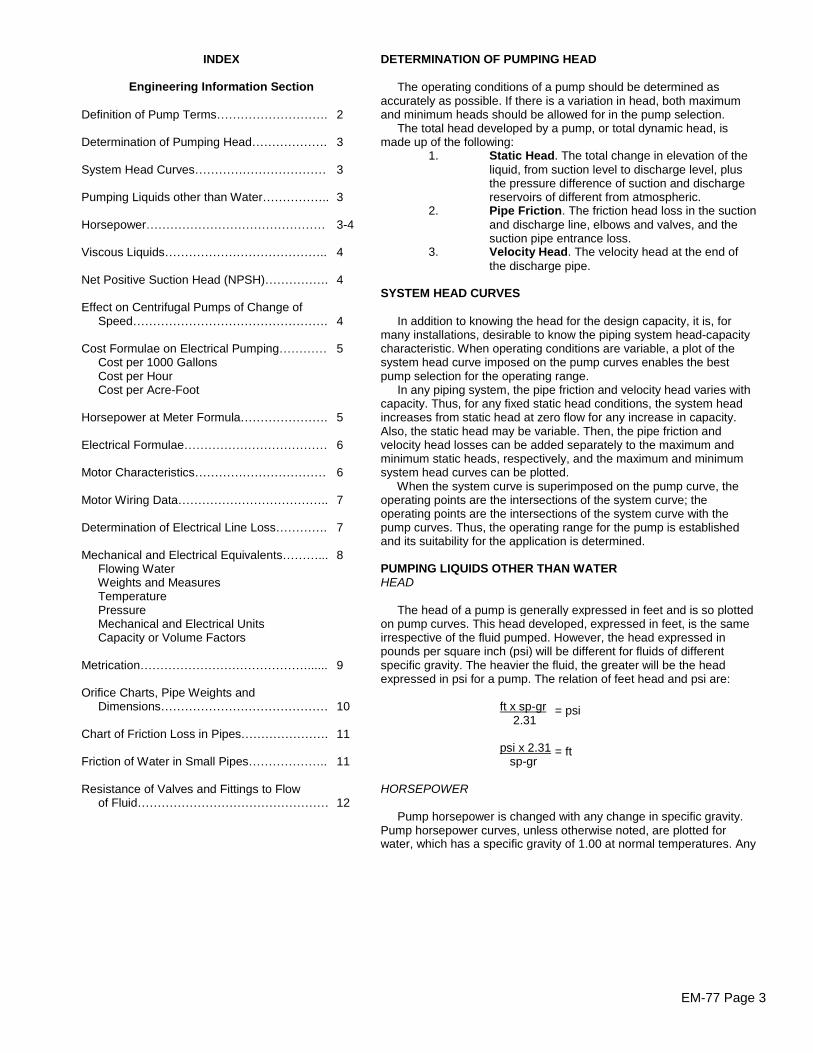
EM-77 Page 3
INDEX
Engineering Information Section
Definition of Pump Terms……………………….
Determination of Pumping Head……………….
System Head Curves……………………………
Pumping Liquids other than Water……………..
Horsepower………………………………………
Viscous Liquids…………………………………..
Net Positive Suction Head (NPSH)…………….
Effect on Centrifugal Pumps of Change ofSpeed………………………………………….
Cost Formulae on Electrical Pumping…………Cost per 1000 GallonsCost per HourCost per Acre-Foot
Horsepower at Meter Formula………………….
Electrical Formulae………………………………
Motor Characteristics……………………………
Motor Wiring Data………………………………..
Determination of Electrical Line Loss………….
Mechanical and Electrical Equivalents………...Flowing WaterWeights and MeasuresTemperaturePressureMechanical and Electrical UnitsCapacity or Volume Factors
Metrication……………………………………......
Orifice Charts, Pipe Weights andDimensions……………………………………
Chart of Friction Loss in Pipes………………….
Friction of Water in Small Pipes………………..
Resistance of Valves and Fittings to Flowof Fluid…………………………………………
2
3
3
3
3-4
4
4
4
5
5
6
6
7
7
8
9
10
11
11
12
DETERMINATION OF PUMPING HEAD
The operating conditions of a pump should be determined asaccurately as possible. If there is a variation in head, both maximumand minimum heads should be allowed for in the pump selection.
The total head developed by a pump, or total dynamic head, ismade up of the following:
1. Static Head. The total change in elevation of theliquid, from suction level to discharge level, plusthe pressure difference of suction and dischargereservoirs of different from atmospheric.
2. Pipe Friction. The friction head loss in the suctionand discharge line, elbows and valves, and thesuction pipe entrance loss.
3. Velocity Head. The velocity head at the end ofthe discharge pipe.
SYSTEM HEAD CURVES
In addition to knowing the head for the design capacity, it is, formany installations, desirable to know the piping system head-capacitycharacteristic. When operating conditions are variable, a plot of thesystem head curve imposed on the pump curves enables the bestpump selection for the operating range.
In any piping system, the pipe friction and velocity head varies withcapacity. Thus, for any fixed static head conditions, the system headincreases from static head at zero flow for any increase in capacity.Also, the static head may be variable. Then, the pipe friction andvelocity head losses can be added separately to the maximum andminimum static heads, respectively, and the maximum and minimumsystem head curves can be plotted.
When the system curve is superimposed on the pump curve, theoperating points are the intersections of the system curve; theoperating points are the intersections of the system curve with thepump curves. Thus, the operating range for the pump is establishedand its suitability for the application is determined.
PUMPING LIQUIDS OTHER THAN WATERHEAD
The head of a pump is generally expressed in feet and is so plottedon pump curves. This head developed, expressed in feet, is the sameirrespective of the fluid pumped. However, the head expressed inpounds per square inch (psi) will be different for fluids of differentspecific gravity. The heavier the fluid, the greater will be the headexpressed in psi for a pump. The relation of feet head and psi are:
ft x sp-gr2.31
psi x 2.31sp-gr
HORSEPOWER
Pump horsepower is changed with any change in specific gravity.Pump horsepower curves, unless otherwise noted, are plotted forwater, which has a specific gravity of 1.00 at normal temperatures. Any
= psi
= ft
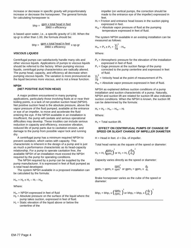
EM-77 Page 4
increase or decrease in specific gravity will proportionatelyincrease or decrease the horsepower. The general formulafor calculating horsepower is:
gpm x total head in feet3960 x efficiency
is based upon water, i.e., a specific gravity of 1.00. When thesp-gr is other than 1.00, the formula should be:
gpm x total head in feet3960 x efficiency
VISCOUS LIQUIDS
Centrifugal pumps can satisfactorily handle many oils andother viscous liquids. Applications of pumps to viscous liquidsshould be referred to the factory. When pumping viscousliquids, centrifugal pump characteristics are radically altered.The pump head, capacity, and efficiency all decrease whenpumping viscous liquids. The variation is more pronounced asthe liquid becomes more viscous, and is not a linear function.
NPSH(NET POSITIVE SUCTION HEAD)
A major problem encountered in many pumpingapplications, particularly those involving fluids at or near theirboiling points, is a lack of net positive suction head (NPSH).Net positive suction head is the absolute pressure, above thevapor pressure of the fluid pumped, available at the entranceor eye of an impeller, to move and accelerate the fluidentering the eye. If the NPSH available in an installation isinsufficient, the pump will cavitate and serious operationaldifficulties may develop. These troubles can include seriousreduction in capacity and efficiency, excessive vibration,reduced life of pump parts due to cavitation erosion, anddamage to the pump from possible vapor lock and runningdry.
A centrifugal pump has a minimum required NPSH toprevent cavitation, which varies with capacity. Thischaracteristic is inherent in the design of a pump and is justas much a performance characteristic as its head-capacityrelationship. For a pump to operate cavitation free, theavailable NPSH of an installation must exceed the NPSHrequired by the pump for operating conditions.
The NPSH required by a pump can be supplied by thepump manufacturer. It is expressed in feet of fluid pumped asis total head developed.
The system NPSH available in a proposed installation canbe calculated by the formula:
Hsv = Hp ± Hz –Hf –Hvp
Where:
Hsv = NPSH expressed in feet of fluidHp = Absolute pressure on the surface of the liquid where the
pump takes suction, expressed in feet of fluid.Hz = Static elevation of the liquid above or below the
centerline of the
bhp =
impeller (on vertical pumps, the correction should bemade to the entrance eye of the impeller) expressed infeet.
Hf = Friction and entrance head losses in the suction pipingexpressed in feet.
Hvp = Absolute vapor pressure of fluid at the pumpingtemperature expressed in feet of fluid.
The system NPSH available in an existing installation can bemeasured as follows:
Hsv = Pa ± Ps + - Hvp
Where:
Pa = Atmospheric pressure for the elevation of the installationexpressed in feet of fluid.
Ps = Gage pressure at the suction flange of the pumpcorrected to the pump centerline and expressed in feetof fluid.
= Velocity head at the point of measurement of Ps.
Hvp = Absolute vapor pressure expressed in feet of fluid.
NPSH as explained defines suction conditions of a pumpinstallation and suction characteristic of a pump. Naturally,NPSH and suction lift are related for suction lift also indicatessuction conditions. When the NPSH is known, the suction liftcan be determined by the formula:
Hs = Hp –Hsv –Hvp –Hf
Where:
Hs = Total suction lift.
EFFECT ON CENTRIFUGAL PUMPS OF CHANGE OFSPEED OR SLIGHT CHANGE OF IMPELLER DIAMETER
H = Head in feet. d = Dia. of impeller.
Total head varies as the square of the speed or diameter:
H2 = H1 ( ) or H2 = H1 ( )Capacity varies directly as the speed or diameter:
gpm2 = gpm1 x or gpm2 = gpm1 x
Brake horsepower varies as the cube of the speed ordiameter:
bhp2 = bhp1 x ( ) or bhp2 = bhp1 x ( )
bhp = x sp-gr Vs2
2g
Vs2
2g
rpm22
rpm1
d22
d1
rpm2 d2
rpm1 d1
rpm23 d2
3
rpm1 d1
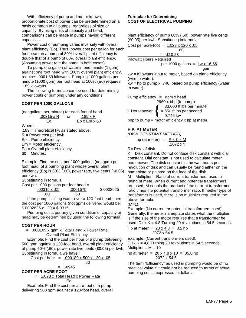
EM-77 Page 5
With efficiency of pump and motor known,proportionate cost of power can be predetermined on abasis common to all pumps, regardless of size orcapacity. By using units of capacity and head,comparisons can be made in pumps having differentcapacities.
Power cost of pumping varies inversely with overallplant efficiency (Eo). Thus, power cost per gallon for eachfoot head on a pump of 30% overall plant efficiency isdouble that of a pump of 60% overall plant efficiency.(Assuming power rate the same in both cases).
To pump one gallon of water in one minute (1 gpm)against one foot head with 100% overall plant efficiency,requires .0001 89 kilowatts. Pumping 1000 gallons perminute (1000 gpm) per foot head at 100% (Eo) requires.189 kilowatts.
The following formulae can be used for determiningpower costs of pumping under any conditions:
COST PER 1000 GALLONS
(not gallons per minute) for each foot of head= .00315 x R or .189 x R
Eo Ep x Em x 60Where:.189 = Theoretical kw as stated above.R = Power cost per kwh.Ep = Pump efficiency.Em = Motor efficiency.Eo = Overall plant efficiency.60 = Minutes.
Example: Find the cost per 1000 gallons (not gpm) perfoot head, of a pumping plant whose overall plantefficiency (Eo) is 60% (.60), power rate, five cents ($0.05)per kwh.Substituting in formula:Cost per 1000 gallons per foot head =
.00315 x .05 = .0001575 = $.0002625.60 .60
If the pump is lifting water over a 120-foot head, thenthe cost per 1000 gallons (not gpm) delivered would be:$.0002625 x 120 = $.0315
Pumping costs per any given condition of capacity orhead may be determined by using the following formula:
COST PER HOUR= .000189 x gpm x Total Head x Power Rate
Overall Plant EfficiencyExample: Find the cost per hour of a pump delivering
500 gpm against a 120-foot head, overall plant efficiencyof pump 60% (.60), power rate five cents ($0.05) per kwh.Substituting in formula we have:
Cost per hour = .000189 x 500 x 120 x .05.60
= $0945COST PER ACRE-FOOT
= 1.023 x Total Head x Power RateEo
Example: Find the cost per acre-foot of a pumpdelivering 500 gpm against a 120-foot head, overall
Formulae for DeterminingCOST OF ELECTRICAL PUMPING
plant efficiency of pump 60% (.60), power rate five cents($0.05) per kwh. Substituting in formula:Cost per acre-foot = 1.023 x 120 x .05
.60= $10.23 a
Kilowatt Hours Requiredper 1000 gallons = kw x 16.66
gpmkw = Kilowatts input to meter, based on plane efficiency(wire to water).kw = hp to pump x .746, based on pump efficiency (waterto water).
Pump efficiency = gpm x head2960 x bhp (to pump)
= 33,000 ft lbs per minute1 Horsepower = 550 ft lbs per second
= 0.746 kwbhp to pump = motor efficiency x hp at meter.
H.P. AT METER(DISK CONSTANT METHOD)
hp (at meter) = R x K x M.2072 x t
R= Rev. of disk.K = Disk constant. Do not confuse disk constant with dialconstant. Dial constant is not used to calculate meterhorsepower. The disk constant is the watt hours perrevolution of disk and can usually be found either on thenameplate or painted on the face of the disk.M = Multiplier = Ratio of current transformers used torating of mete. When current and potential transformersare used, M equals the product of the current transformerratio times the potential transformer ratio. If neither type oftransformer is used, there is no multiplier required in theabove formula.(M=1).Example: (No current or potential transformers used).Generally, the meter nameplate states what the multiplieris if the size of the motor requires that a transformer beused. Disk K = 4.8 Turning 20 revolutions in 54.5 seconds.Hp at meter = 20 x 4.8 = 8.5 hp
.2072 x 54.5Example: (Current transformers used).Disk K = 4,8 Turning 20 revolutions in 54.5 seconds.Multiplier = M = 10hp at meter = 20 x 4.8 x 10 = 85.0 hp
.2072 x 54.5The term “Efficiency” as used in pumping would be of no practical value if it could not be reduced to terms of actualpumping costs, expressed in dollars.
{

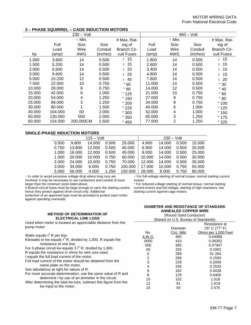
EM-77 Page 7
MOTOR WIRING DATAFrom National Electrical Code
3 –PHASE SQUIRREL –CAGE INDUCTION MOTORS230 –Volt 460 –Volt
hp
FullLoad(amp)
†Min.SizeWireAWG
SizeConduit(inches)
# Max. Rat-ing of
Branch Cir-cuit Fuses
FullLoad(amp)
†Min.SizeWireAWG
SizeConduit(inches)
# Max. Rat-ing of
Branch Cir-cuit Fuses
1.0001.5002.0003.0005.0007.50010.00015.00020.00025.00030.00040.00050.00060.000
3.6005.2006.6009.60015.20022.00028.00042.00054.00068.00080.000104.000130.000154.000
1414141412108643100000
200,000CM
0.5000.5000.5000.5000.5000.7500.7501.0001.2501.2501.5002.0002.0002.500
‡ 15‡ 15‡ 20‡ 25‡ 45° 60° 80° 125° 150° 200° 225° 300° 350° 450
1.8002.6003.4004.8007.60011.00014.00021.00027.00034.00040.00052.00065.00077.000
1414141414141210886432
0.5000.5000.5000.5000.5000.5000.5000.7500.7500.7501.0001.0001.2501.250
‡ 15‡ 15‡ 15‡ 15‡ 20° 30° 40° 60° 80° 100° 125° 150° 175° 225
METHOD OF DETERMINATION OFELECTRICAL LINE LOSS
Used when meter is located an appreciable distance from thepump motor
Watts equals I2 R per line.Kilowatts or kw equals I2 R, divided by 1,000. R equals the
resistance of one line.For 3-phase circuit kw equals 3 I2 R, divided by 1,000.R equals the resistance in ohms for wire size used.I equals the full load current of the motor.Full load current of the motor should be obtained from the
name plate on the motor.See tabulations at right for values of R.For more accurate determination, use the same value of R and
determine I by use of an ammeter in the circuit.After determining the total kw loss, subtract this figure from the
kw input to the motor.
DIAMETER AND RESISTANCE OF STANDARDANNEALED COPPER WIRE
(Round Solid Conductor)(Based on U.S. Bureau of Standards)
No.A.W.D.000000000023468
101214
DiameterCirc. Mils
4604103653252892582292041621291028164
Resistance at25° C (77° F)
Ohms per 1,000 Feet0.049980.063020.079470.100201 2640.15930.20090.25330.40280.64051.0181.6192.575
SINGLE-PHASE INDUCTION MOTORS115 –Volt 230 –Volt
0.5000.7501.0001.5002.0003.0005.000
9.80013.80016.00020.00024.00034.00056.000
14.00012.00012.00010.00010.0006.0004.000
0.5000.5000.5000.7500.7500.7501.250
25.00040.00045.00060.00070.000
100.000150.000
4.9006.9008.00010.00012.00017.00028.000
14.00014.00014.00014.00014.00010.0008.000
0.5000.5000.5000.5000.5000.7500.750
15.00020.00025.00030.00035.00050.00080.000
†In order to avoid excessive voltage drop where long runs areinvolved, it may be necessary to use conductors and conduit of sizeslarger than the minimum sizes listed above.# Branch-circuit fuses must be large enough to carry the starting current,hence they protect against short-circuit only. Additionalprotection of an approved type must be provided to protect each motoragainst operating overloads.
‡For full-voltage starting of normal torque, normal starting currentmotors.° For reduced-voltage starting of normal torque, normal startingcurrent-motors and full-voltage, starting of high-reactance, lowstarting current squirrel-cage motors.
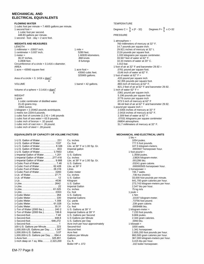
EM-77 Page 8
MECHANICAL ANDELECTRICAL EQUIVALENTS
FLOWING WATER1 cubic foot per minute = 7.4805 gallons per minute.1 second foot =
1 cubic foot per second.448.83 gallons per minute.
1 second - foot - day = 2 acre feet.
WEIGHTS AND MEASURESLENGTH1 millimeter = .03937 inch. 1 mile =1 centimeter = 3.937 inch. 5280 feet.1 meter = 1.60935 kilometers.
39.37 inches. .868 knots3.2808 feet. 8 furlongs
Circumference of a circle = 3.1416 x diameter.AREA1 acre = 43560 square feet 1 acre foot =
43560 cubic feet.325900 gallons.
Area of a circle = 3. 1416 x diam2
4VOLUME 1 barrel = 42 gallons.
Volume of a sphere = 3.1416 x diam3
6WEIGHT1 gram
1 cubic centimeter of distilled water.15.43 grains troy..0353 ounce.
1 kilogram = 2.20462 pounds avoirdupois.1 metric ton 2204.6 pounds.1 cubic foot of concrete (1:2:4) = 146 pounds1 cubic foot of sea water = 63.9 pounds.1 cubic inch of bronze = .32 pound.1 cubic inch of cast iron = .26 pound.1 cubic inch of steel = .28 pound.
EQUIVALENTS OF CAPACITY OR VOLUME FACTORS
1-U.S. Gallon of Water………..………. 2311-U.S. Gallon of Water………….….. .13371-U.S. Gallon of Water……….……… 8.3261-U.S. Gallon of Water……………..… .8331-U.S. Gallon of Water……….....… 3.78531-Imperial Gallon of Water…………. 1.2011-Imperial Gallon of Water.……….277.4181-Imperial Gallon of Water…….……. 9.9881-Cubic Foot of Water………………... 7.481-Cubic Foot of Water…………….. 62.4281-Cubic Foot of Water…………….. 28.3161-Cubic Foot of Water…………..….. .02831-Lb. of Water…………………….…. 27.711-Lb. of Water………………………….. .121-Lb………………………………..…. .45361-Litre………………………….…….. .26421-Litre……………………………...……. .221-Litre…………………………...….. 61.0251-Litre……………………………….... .03531-Cubic Meter……………...……..…… 2641-Cubic Meter………………...……….. 2201-Cubic Meter…………………….…. 1.3081-Cubic Meter…………………..….. 61,0281-Cubic Meter………………..……… 35.311-Ton of Water (2000 lbs.)…………. 240 21-Ton of Water (2000 lbs.)…………. 199.81-Second-foot………………………… 7.481-Second-foot……………………….. 448.81-Second-foot……………………. 646,2721-Second-foot……………………………. 1100-U.S. Gallons per Minute………… 2231,000,000-US. Gallons per Day…… 1.5471,000,000-U.S. Gallons……………… 3.071,000,000-U.S. Gallons per Day….. 694.41-Acre foot………………………... 325,8511-Inch deep on 1 sq. Mile……... 2,323,200
Cu. inchesCu. footLbs. at 39° F or 1.00 Sp. Gr.Imperial gallonLitresU.S. GallonsCu. inchesLbs. at 39° F or 1.00 Sp. Gr.U.S. GallonsLbs. at 39° FLitresCubic meterCu. inchesU.S. GallonKilogramU.S. GallonImperial GallonCu. inchesCu. footU.S. GallonsImperial GallonsCu. yardsCu. inchesCu. feetU.S. Gallons at 39° FImperial Gallons at 39° FU.S. Gallons per SecondU.S Gallons per MinuteU.S. Gallons per DayAcre inch per hour approximatelySecond-foolSecond-feetAcre feetGallons per MinuteGallonsCu. ft.Boiler HP x .072
MECHANICAL AND ELECTRICAL UNITS1 btu =
1054 joules.777.5 foot pounds.107.5 kilogram-meters..0003927 horsepower hour.
1 foot pound =1.3558 joules..13826 kilogram-meter..001286 btu..03241 gram calorie..000000505 horsepower hour.
1 horsepower =745.7 watts..736 Kw (metric)33,000 foot pounds per minute.641,700 gram calories per hour.273,743 kilogram-meters per hour.2,547 btu per hour.75 kg m/s
1 joule =1 Nm.10197 kilogram-meter..73756 foot pound..239 gram calorie..0009486 btu.
1 kilogram-meter =7.233 foot pounds.9.806 joules.2.344 gram calories..0093 btu.
1 kilowatt =1000 watts.1.341 horsepower.2,655,200 foot pounds per hour.860,500 gram calories per hour.367,000 kilogram-meters per hour.3,415 btu per hour..102 boiler horsepower.
TEMPERATURE
Degrees C = x (F - 32) Degrees F= x C+32
PRESSURE
1 atmosphere =760 millimeters of mercury at 32° F.14.7 pounds per square inch.29.921 inches of mercury at 32° t.2116 pounds per square foot.1.033 kilograms per square centimeter.33.947 feet of water at 62° F.10.33 meters of water at 20° C.1.013 bar.
1 foot of air at 32° F and barometer 29.92 =.0761 pound per square foot..0146 inch of water at 62° F.
1 foot of water at 62° F =.433 pound per square inch62.355 pounds per square foot.
.883 inch of mercury at 62° F.821.2 feet of air at 62° F and barometer 29.92.
1 inch of water 62° F =.0361 pound per square inch.5.196 pounds per square foot
.5776 ounce per square inch
.073 5 inch of mercury at 62° F68.44 feet of air at 62° F and barometer 29.92.
1 pound per square inch =2.0355 inches of mercury at 32° F2.0416 inches of mercury at 62° F.2.309 feet of water at 62° F..07031 kilograms per square centimeter
.06804 atmosphere.51.7 millimeters of mercury at 32° F.
5 99 5
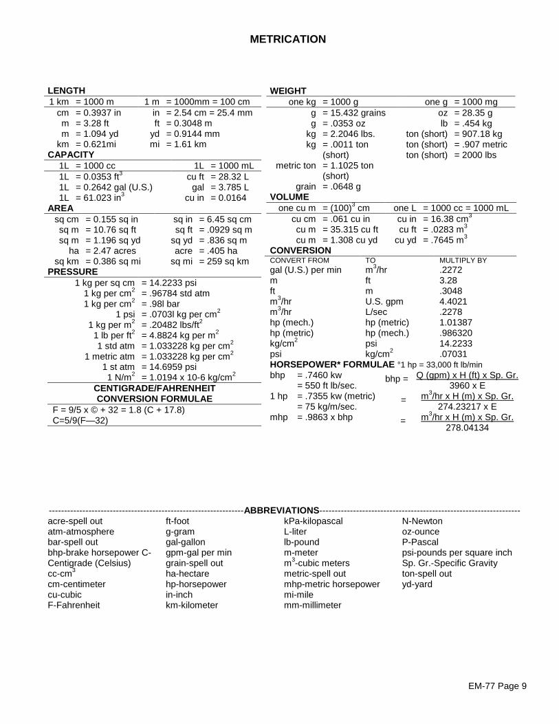
EM-77 Page 9
METRICATION
LENGTH1 km = 1000 m 1 m = 1000mm = 100 cm
cm = 0.3937 in in = 2.54 cm = 25.4 mmm = 3.28 ft ft = 0.3048 mm = 1.094 yd yd = 0.9144 mm
km = 0.621mi mi = 1.61 kmCAPACITY
1L = 1000 cc 1L = 1000 mL1L = 0.0353 ft3 cu ft = 28.32 L1L = 0.2642 gal (U.S.) gal = 3.785 L1L = 61.023 in3 cu in = 0.0164
AREAsq cmsq msq m
hasq km
= 0.155 sq in= 10.76 sq ft= 1.196 sq yd= 2.47 acres= 0.386 sq mi
sq insq ft
sq ydacre
sq mi
= 6.45 sq cm= .0929 sq m= .836 sq m= .405 ha= 259 sq km
PRESSURE1 kg per sq cm = 14.2233 psi
1 kg per cm2 = .96784 std atm1 kg per cm2 = .98l bar
1 psi = .0703l kg per cm2
1 kg per m2 = .20482 lbs/ft2
1 lb per ft2 = 4.8824 kg per m2
1 std atm = 1.033228 kg per cm2
1 metric atm = 1.033228 kg per cm2
1 st atm = 14.6959 psi1 N/m2 = 1.0194 x 10⁻⁶ kg/cm2
CENTIGRADE/FAHRENHEITCONVERSION FORMULAE
F = 9/5 x © + 32 = 1.8 (C + 17.8)C=5/9(F—32)
WEIGHTone kg = 1000 g one g = 1000 mg
gg
kgkg
metric ton
grain
= 15.432 grains= .0353 oz= 2.2046 lbs.= .0011 ton(short)= 1.1025 ton(short)= .0648 g
ozlb
ton (short)ton (short)ton (short)
= 28.35 g= .454 kg= 907.18 kg= .907 metric= 2000 lbs
VOLUMEone cu m = (100)3 cm one L = 1000 cc = 1000 mL
cu cmcu mcu m
= .061 cu in= 35.315 cu ft= 1.308 cu yd
cu incu ft
cu yd
= 16.38 cm3
= .0283 m3
= .7645 m3
CONVERSIONCONVERT FROMgal (U.S.) per minmftm3/hrm3/hrhp (mech.)hp (metric)kg/cm2
psi
TOm3/hrftmU.S. gpmL/sechp (metric)hp (mech.)psikg/cm2
MULTIPLY BY.22723.28.30484.4021.22781.01387.98632014.2233.07031
HORSEPOWER* FORMULAE °1 hp = 33,000 ft lb/minbhp = .7460 kw Q (gpm) x H (ft) x Sp. Gr.
= 550 ft lb/sec. 3960 x E1 hp = .7355 kw (metric) m3/hr x H (m) x Sp. Gr.
= 75 kg/m/sec. 274.23217 x Emhp = .9863 x bhp m3/hr x H (m) x Sp. Gr.
278.04134
----------------------------------------------------------------ABBREVIATIONS------------------------------------------------------------------acre-spell outatm-atmospherebar-spell outbhp-brake horsepower C-Centigrade (Celsius)cc-cm3
cm-centimetercu-cubicF-Fahrenheit
ft-footg-gramgal-gallongpm-gal per mingrain-spell outha-hectarehp-horsepowerin-inchkm-kilometer
kPa-kilopascalL-literlb-poundm-meterm3-cubic metersmetric-spell outmhp-metric horsepowermi-milemm-millimeter
N-Newtonoz-ounceP-Pascalpsi-pounds per square inchSp. Gr.-Specific Gravityton-spell outyd-yard
bhp =
=
=
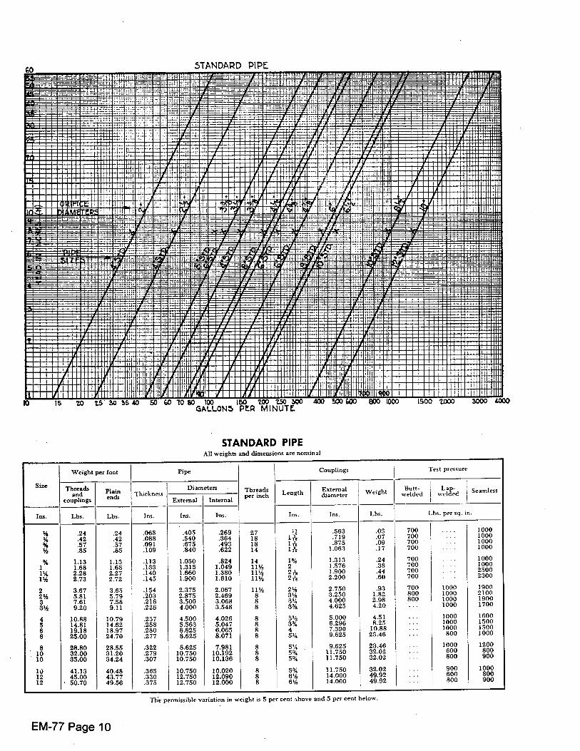
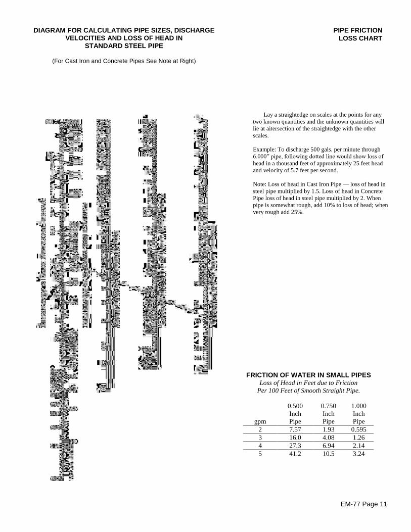
EM-77 Page 11
PIPE FRICTIONLOSS CHART
DIAGRAM FOR CALCULATING PIPE SIZES, DISCHARGEVELOCITIES AND LOSS OF HEAD IN
STANDARD STEEL PIPE
(For Cast Iron and Concrete Pipes See Note at Right)
FRICTION OF WATER IN SMALL PIPESLoss of Head in Feet due to Friction
Per 100 Feet of Smooth Straight Pipe.
0.500 0.750 1.000Inch Inch Inch
gpm Pipe Pipe Pipe2 7.57 1.93 0.5953 16.0 4.08 1.264 27.3 6.94 2.145 41.2 10.5 3.24
Lay a straightedge on scales at the points for anytwo known quantities and the unknown quantities willlie at aitersection of the straightedge with the otherscales.
Example: To discharge 500 gals. per minute through6.000” pipe, following dotted line would show loss of head in a thousand feet of approximately 25 feet headand velocity of 5.7 feet per second.
Note: Loss of head in Cast Iron Pipe— loss of head insteel pipe multiplied by 1.5. Loss of head in ConcretePipe loss of head in steel pipe multiplied by 2. Whenpipe is somewhat rough, add 10% to loss of head; whenvery rough add 25%.

Peerless Pump Company Indianapolis, IN 46207-7026
VERTICAL TURBINE PUMPS SECTION 133 Page 1 August 28, 1989
GENERAL SPECIFICATION FORM
WATER LUBRICATED DEEP WELL TURBINE PUMP
GENERAL REQUIREMENTS: These specifications are intended to cover the furnishing (and deliver) of a complete vertical motor-driven deep well turbine pump for ________________________________________ at _________________________________________. Installation will be made by (owner) (others). OPERATING CONDITIONS: The following are the operating conditions: (1) Size of well (inside diameter) __________ inches (2) Depth of well __________ feet (3) Standing water level below top of well __________ feet (4) Pumping level below top of well at rated pump capacity __________ feet (5) Pumping head or pressure above top of well __________ feet (6) Total pumping head (4 and 5) __________ feet (7) Capacity of pump __________ GPM The total pumping head does not include losses in the pump, which must be allowed by the bidder. The efficiency of the pumping unit shall be as high as correct design and good engineering will permit. All things being equal, consideration will be given to overall pumping costs. MOTORS: The motor thrust bearing shall have ample capacity to carry the weight of all the rotating parts plus the hydraulic thrust of the pump impellers, and have an ample safety factor. This factor should be based on an average life expectancy of five years operation at 24 hours per day. The motor shall be of the full voltage starting, vertical hollow shaft, squirrel cage induction type and shall conform to the standard of the American Institute of Electrical Engineers. The motor shall be a ____ volt, ____ phase, ____ cycle, not more than ____ RPM at no load shall be of proper size to drive the pump continuously under the total head specified with a temperature rise not exceeding 900 C by resistance at service factor load above ambient temperature. (General practice in the pump industry is to operate pumps 1800 RPM for capacities up to 7000 GPM, and at 1200 RPM for capacities from 7000 GPM to 15000 GPM.) PUMP HEAD: A pump head of high grade cast iron or fabricated steel shall be provided for mounting the motor, with an above- ground flanged discharge outlet and a companion flange threaded for ____ inch standard pipe. Alternate for underground discharge: An underground discharge tee with flanged discharge outlet for ____ inch standard connection below the base plate shall be provided.
Subject to change without notice
SECTION 133Page 2August 28, 1989
VERTICAL TURBINE PUMPS Peerless Pump CompanyIndianapolis, IN 46207-7026
PUMP COLUMN ASSEMBLY:The total length of the discharge column shall be feet. The column pipe shall be not less than inches insidediameter and weight not less than pounds per foot. The pipe shall be furnished in interchangeable sections notover ten (10) feet in length, and shall be connected with threaded, sleeve type couplings. The joints are to be buttedto insure perfect alignment after assembly.
The line shafting shall be turned, ground and polished precision shafting of ample size to operate the pump withoutdistortion or vibration. The shaft shall be furnished in interchangeable sections not over ten (10) feet in length, andshall be coupled with strong steel couplings machined from solid bar steel. A non-corrosive flame sprayed stainlesssteel journal shall be placed on each shaft at the bearing point. The stainless steel journal O.D. will be substantiallyflush with the shaft CD. (recess not to be deeper than diameter corresponding to the root diameter of shaft threads).
The column assembly shall have bronze bearing retainers threaded into the pipe couplings and retained by the buttedpipe ends. Each bearing retainer shall contain a water lubricated, cutless rubber bearing designed for vertical turbinepump service.
PUMP BOWL ASSEMBLY:The pump bowls shall be of close grained cast iron having a minimum tensile strength of 30,000 pounds per squareinch, free from blow holes, sand holes, and all other faults; accurately machined and fitted to close dimensions.
The impeller shaft shall be of stainless steel of not less than 12% chrome. The impeller shaft shall be supported by acombination of water lubricated, fluted rubber and bronze bearings.
The impeller shall be of (bronze) (cast iron), accurately machined and finished, and mechanically balanced. They shallbe securely fastened to the impeller shaft with a tapered bushing.
Each bowl shall have an impeller seal ring to prevent slippage of water between bowl and impeller. The impellers shallbe adjustable by means of a top shaft nut at the top of the motor.
SUCTION PIPE AND STRAINER:A suction pipe ten (10) feet in length and of proper diameter and same material as pump column shall be provided. Astrainer having a net inlet opening area of not less than four times the area of the suction pipe shall be provided.
WATER LEVEL INDICATOR:A suitable air line of galvanized iron pipe, copper or plastic tubing of sufficient length to extend from the surface to thetop of the bowl assembly, with altitude gage reading in feet, and connections for air pump, shall be furnished.
DESCRIPTIVE MATTER:The bidder shall submit with each proposal complete dimensional prints and descriptive matter, including performancecharacteristics, to clearly cover the equipment offered.
Motor efficiencies and power factors for one-half (1/2), three-quarters (3/4), and full load conditions shall be submitted.
VARIATIONS AND EXCEPTIONS:Variations from the above specifications will be considered providing the bidder calls particular attention to suchexceptions and explains in detail the reasons and advantages for the exceptions.
The reserves the right to reject any or all bids
Subject to change without notice.
CityPurchaser
Peerless Pump Company Indianapolis IN, 46207-7026
VERTICAL TURBINE PUMPS SECTION 133 Page 3 May 22, 1978
The specifications on pages 1 and 2 for a standard water lubricated turbine pump are non-restrictive and will permit most vertical pump manufacturers to quote and meet the requirements of these specifications. It is not the desire or intent of Peerless Pump to prohibit open competitive bidding and for that reason none of the special features of the modern Peerless Pump are incorporated in these specifications. A Peerless water lubricated pump quotation would meet all the requirements of the foregoing specifications and, in addition, would include the following special features. PUMP COLUMN ASSEMBLY: The pump column assembly conforms to the foregoing specifications but with the advantage of the following special features.
(1) The bowl provides a side seal at the impeller skirt and, in addition, a resilient neoprene ring reinforced with an embedded steel core is installed in the bowl directly below the impeller skirt. This "lateral bowl wear ring" is very durable and, being resilient, does not wear the impeller skirt. Original capacities and efficiencies can be maintained by a simple adjustment of the top shaft nut at the top of the motor. If the side seal wears, the bottom neoprene seal ring retains its form and dimension and restricts the leakage flow at the impeller skirt.
(2) Peerless Pump bowls are coated inside with a smooth vitreous enamel which reduces friction losses in the water passages and thus gives better efficiency. The enameling also reduces corrosion and sand wear.
(3) Each Peerless Pump intermediate bowl is constructed by using a bronze bearing and neoprene bearing to support the impeller shaft which gives the longest possible life based in the widest range of pumping conditions.
We do not recommend that any of these special features be incorporated in your specifications because they may tend to be restrictive for other manufacturers, but a Peerless Pump will have these features whether they are specified or not.
Subject to change without notice

Blank
Peerless Pump Company Indianapolis, IN 46207-7026
VERTICAL TURBINE PUMPS SECTION 133 Page 5 August 28, 1989
GENERAL SPECIFICATION FORM
OIL LUBRICATED DEEP WELL TURBINE PUMP GENERAL REQUIREMENTS: These specifications are intended to cover the furnishing (and delivery) of a complete vertical motor-driven deep well turbine pump for at a Installation will be made by (owner) (others). OPERATING CONDITIONS: The following are the operating conditions: (1) Size of well (inside diameter) inches (2) Depth of well feet (3) Standing water level below top of well feet (4) Pumping level below top of well at rated pump capacity feet (5) Pumping head or pressure above top of well feet (6) Total pumping head (4 and 5) feet (7) Capacity of pump GPM The total pumping head does not include losses in the pump, which must be allowed by the bidder. The efficiency of the pumping unit shall be as high as correct design and good engineering will permit. Al things being equal, consideration will be given to overall costs. MOTOR: The motor thrust bearing shall have ample capacity to carry the weight of all the rotating parts plus the hydraulic thrust of the pump impellers, and have an ample safety factor. This factor should be based on an average life expectancy of five years operation at 24 hours per day. The motor shall be of the full voltage starting, vertical hollow shaft, squirrel cage induction type and shall conform to the standard of the American Institute of Electrical Engineers. The motor shall be a volt, phase, cycle, not more than RPM at no load and shall be of proper size to drive the pump continuously under the total head specified with a temperature rise not exceeding 90° C by resistance at service factor load above ambient temperature. (General practice in the pump industry is to operate pumps 1800 RPM for capacities up to 7000 GPM and at 1200 RPM for capacities from 7000 GPM to 15,000 GPM.) PUMP HEAD: A pump head of high grade cast iron or fabricated steel shall be provided for mounting the motor, with an above-ground flanged discharge outlet and a companion flange threaded for inch standard pipe. Alternate for underground discharge: An underground discharge tee with flanged discharge outlet for inch standard connection below the base plate shall be provided.
Subject to change without notice.
SECTION 133 Page 6 August 28, 1989
VERTICAL TURBINE PUMPS Peerless Pump Company Indianapolis, IN 46207-7026
PUMP COLUMN ASSEMBLY: The total length of the discharge column shall be feet. The column pipe shall be not less than inches inside diameter and weight not less than pounds per foot. The pipe shall be furnished in interchangeable sections not over ten feet in length, and shall be connected with threaded steel sleeve type couplings. The joints are to be butted to insure perfect alignment after assembly. The line shaft shall be turned, ground and polished precision shafting of ample size to operate the pump without distortion or vibration. The shaft shall be furnished in interchangeable sections not over ten feet in length and shall be coupled with strong steel couplings machined from solid bar steel. The shaft enclosing tube shall be interchangeable sections, not over five feet in length, of extra strong pipe to receive bronze couplings, which will also act as line shaft bearings. Bearings shall be lubricated by an oiler assembly located on the pump head. PUMP BOWL ASSEMBLY: The pump bowls shall be of close grained cast iron having a minimum tensile strength of 30,000 pounds per square inch, free from blow holes, sand holes, and all other faults; accurately machined and fitted to close dimensions. The impeller shaft shall be of stainless steel of not less than 12% chrome. No so-called rustless iron will be considered. The impeller shaft shall be supported by water lubricated bronze bearings. The impeller shall be of (bronze) (cast iron), accurately machined and finished, and mechanically balanced. They shall be securely fastened to the impeller shaft with a tapered bushing. Each bowl shall provide a side and bottom seal at the impeller skirt to prevent slippage of water between bowl and impeller. The impellers shall be adjustable by means of a top shaft nut at the top of the motor. SUCTION PIPE AND STRAINER: A suction pipe ten feet in length and of proper diameter and same material as pump column shall be provided. A strainer having a net inlet opening of not less than four times the area of the suction pipe shall be provided. WATER LEVEL INDICATOR: A suitable air line of galvanized iron pipe, copper or plastic tubing of sufficient length to extend from the surface to the top of the bowl assembly, with altitude gage reading in feet, and connections for air pump, shall be furnished. DESCRIPTIVE MATTER: The bidder shall submit with each proposal complete dimensional prints and descriptive matter, including performance characteristics, to clearly cover the equipment offered. Motor efficiencies and power factors for one-half, three-quarters and full load conditions shall be submitted. VARIATIONS AND EXCEPTIONS: Variations from the above specifications will be considered provided the bidder calls particular attention to such exceptions and explains in detail the reasons and advantages for the exceptions. The (City) (Purchaser) reserves the right to reject any or all bids.
Subject to change without notice.
Peerless Pump Company Indianapolis, IN 46207-7026
VERTICAL TURBINE PUMPS SECTION 133 Page 7 May 22, 1978
The specifications on pages 5 and 6 for a standard oil lubricated turbine pump are non-restrictive and will permit most vertical pump manufacturers to quote and meet the requirements of these specifications. It is not the desire or intent of Peerless Pump to prohibit open competitive bidding and for that reason, none of the special features of the modern Peerless Pump are incorporated in these specifications. A Peerless oil lubricated pump quotation would meet all the requirements of the foregoing specifications and, in addition, would include the following special features. TUBE NUT ASSEMBLY: The tube nut assembly has a bronze sleeve bearing in the tube nut cap. This bearing, which is lubricated by the oiler assembly, gives additional support to the top shaft before it enters the motor. PUMP COLUMN ASSEMBLY: The pump column assembly conforms to the foregoing specifications, but with the advantage of the following special feature. Since each tube bearing in the enclosing tube receives lubrication from the oiler assembly at the pump head, a spiral groove is provided in each bearing to allow the oil to feed from each bearing to the one below. The spiral groove helps maintain a film of oil between the shaft and the close bearing bore, thereby reducing the wear factor. PUMP BOWL ASSEMBLY: Peerless Pump bowls conform to the specifications as written, but they also include the following special features.
(1)
(2)
(3)
The bowl provides a side seal at the impeller skirt and, in addition, a resilient neoprene ring reinforced with an embedded steel core is installed in the bowl directly below the impeller skirt. This “lateral bowl wear ring” is very durable and, being resilient, does not wear the impeller skirt. Original capacities and efficiencies can be maintained by a simple adjustment of the top shaft nut at the top of the motor. If the side seal wears, the bottom neoprene seal ring retains its form and dimension and restricts leakage flow at the impeller skirt. Peerless Pump bowls are coated inside with a smooth vitreous enamel which reduces friction losses in the water passages and thus gives better efficiency. The enameling also reduces corrosion and sand wear. Each Peerless Pump intermediate bowl is constructed by using a bronze bearing and a neoprene bearing to support the impeller shaft which gives the longest possible life based on the widest range of pumping conditions.
We do not recommend that any of these special features be incorporated in your specifications because they may tend to be restrictive for other manufacturers, but a Peerless Pump will have these features whether they are specified or not.
Subject to change without notice.

Blank
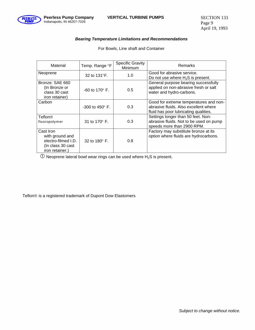
Peerless Pump Company Indianapolis, IN 46207-7026
VERTICAL TURBINE PUMPS SECTION 133 Page 9 April 19, 1993
Bearing Temperature Limitations and Recommendations
For Bowls, Line shaft and Container
Material Temp. Range °F Specific Gravity Minimum Remarks
Neoprene 32 to 131°F. 1.0 Good for abrasive service. Do not use where H2S is present.
Bronze: SAE 660 (In Bronze or class 30 cast iron retainer)
-60 to 170° F. 0.5
General purpose bearing successfully applied on non-abrasive fresh or salt water and hydro-carbons.
Carbon -300 to 450° F. 0.3
Good for extreme temperatures and non-abrasive fluids. Also excellent where fluid has poor lubricating qualities.
Teflon® fluoropolymer 31 to 170° F. 0.3
Settings longer than 50 feet. Non-abrasive fluids. Not to be used on pump speeds more than 2900 RPM.
Cast Iron with ground and electro-filmed I.D. (In class 30 cast iron retainer.)
32 to 180° F. 0.8
Factory may substitute bronze at its option where fluids are hydrocarbons.
Neoprene lateral bowl wear rings can be used where H2S is present. Teflon® is a registered trademark of Dupont Dow Elastomers
Subject to change without notice.
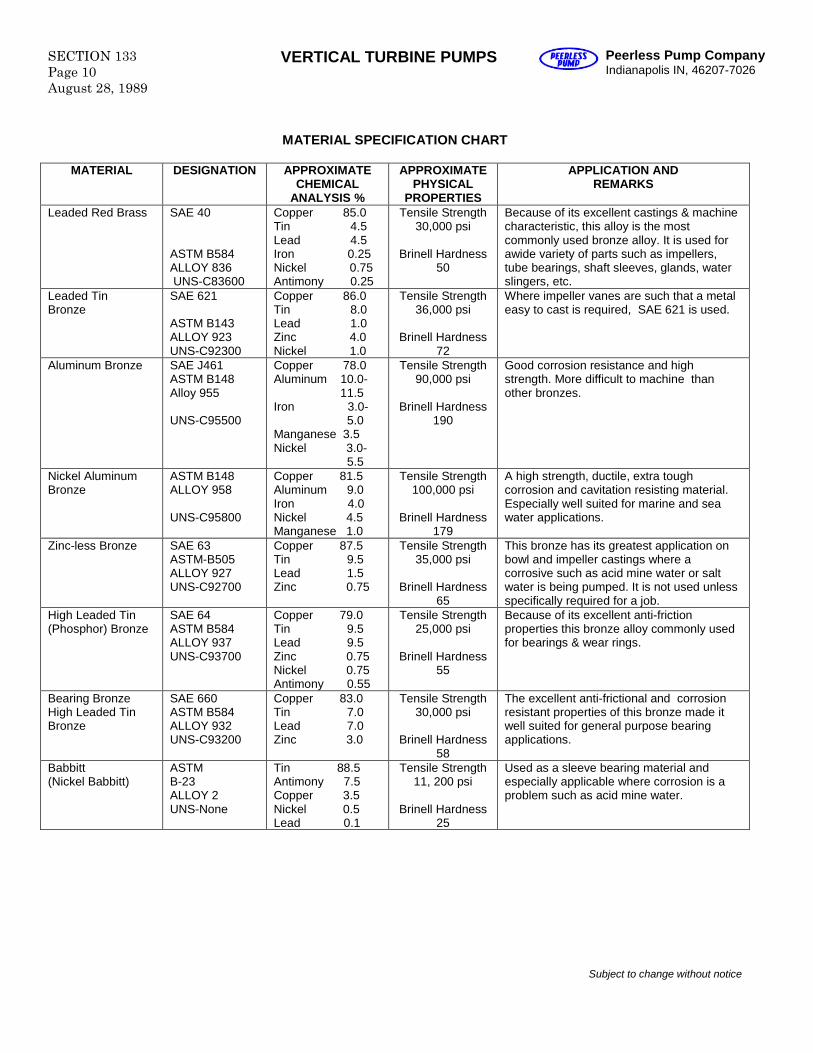
SECTION 133Page 10August 28, 1989
VERTICAL TURBINE PUMPS Peerless Pump CompanyIndianapolis IN, 46207-7026
MATERIAL SPECIFICATION CHART
MATERIAL DESIGNATION APPROXIMATECHEMICAL
ANALYSIS %
APPROXIMATEPHYSICAL
PROPERTIES
APPLICATION ANDREMARKS
Leaded Red Brass SAE 40
ASTM B584ALLOY 836UNS-C83600
Copper 85.0Tin 4.5Lead 4.5Iron 0.25Nickel 0.75Antimony 0.25
Tensile Strength30,000 psi
Brinell Hardness50
Because of its excellent castings & machinecharacteristic, this alloy is the mostcommonly used bronze alloy. It is used forawide variety of parts such as impellers,tube bearings, shaft sleeves, glands, waterslingers, etc.
Leaded TinBronze
SAE 621
ASTM B143ALLOY 923UNS-C92300
Copper 86.0Tin 8.0Lead 1.0Zinc 4.0Nickel 1.0
Tensile Strength36,000 psi
Brinell Hardness72
Where impeller vanes are such that a metaleasy to cast is required, SAE 621 is used.
Aluminum Bronze SAE J461ASTM B148Alloy 955
UNS-C95500
Copper 78.0Aluminum 10.0-
11.5Iron 3.0-
5.0Manganese 3.5Nickel 3.0-
5.5
Tensile Strength90,000 psi
Brinell Hardness190
Good corrosion resistance and highstrength. More difficult to machine thanother bronzes.
Nickel AluminumBronze
ASTM B148ALLOY 958
UNS-C95800
Copper 81.5Aluminum 9.0Iron 4.0Nickel 4.5Manganese 1.0
Tensile Strength100,000 psi
Brinell Hardness179
A high strength, ductile, extra toughcorrosion and cavitation resisting material.Especially well suited for marine and seawater applications.
Zinc-less Bronze SAE 63ASTM-B505ALLOY 927UNS-C92700
Copper 87.5Tin 9.5Lead 1.5Zinc 0.75
Tensile Strength35,000 psi
Brinell Hardness65
This bronze has its greatest application onbowl and impeller castings where acorrosive such as acid mine water or saltwater is being pumped. It is not used unlessspecifically required for a job.
High Leaded Tin(Phosphor) Bronze
SAE 64ASTM B584ALLOY 937UNS-C93700
Copper 79.0Tin 9.5Lead 9.5Zinc 0.75Nickel 0.75Antimony 0.55
Tensile Strength25,000 psi
Brinell Hardness55
Because of its excellent anti-frictionproperties this bronze alloy commonly usedfor bearings & wear rings.
Bearing BronzeHigh Leaded TinBronze
SAE 660ASTM B584ALLOY 932UNS-C93200
Copper 83.0Tin 7.0Lead 7.0Zinc 3.0
Tensile Strength30,000 psi
Brinell Hardness58
The excellent anti-frictional and corrosionresistant properties of this bronze made itwell suited for general purpose bearingapplications.
Babbitt(Nickel Babbitt)
ASTMB-23ALLOY 2UNS-None
Tin 88.5Antimony 7.5Copper 3.5Nickel 0.5Lead 0.1
Tensile Strength11, 200 psi
Brinell Hardness25
Used as a sleeve bearing material andespecially applicable where corrosion is aproblem such as acid mine water.
Subject to change without notice
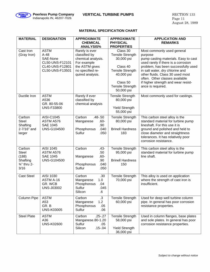
Peerless Pump Company Indianapolis IN, 46207-7026
VERTICAL TURBINE PUMPS SECTION 133 Page 11 August 28, 1989
MATERIAL SPECIFICATION CHART
MATERIAL DESIGNATION APPROXIMATE
CHEMICAL ANALYSIS%
APPROXIMATE PHYSICAL PROPERTIES
APPLICATION AND REMARKS
Cast Iron (Gray Iron)
ASTM A-48 SAE-None CL50-UNS-F12101 CL40-UNS-F12801 CL50-UNS-F13501
Rarely is ever classified by chemical analysis. For example the ASTM gives no specified re- quired analysis.
Class 30 Tensile Strength
30,000 psi
Class 40 Tensile Strength
40,000 psi
Class 50 Tensile Strength
50,000 psi
Most commonly used general purpose pump casting materials. Easy to cast used rarely if there is a corrosion problem, has been successfully used in salt water, dry chlorine and other fluids. Class 30 used most often. Other classes available if higher strength and wear resist- ance is required.
Ductile Iron ASTM A536 GR. 80-55-06 UNS-F33800
Rarely if ever classified by chemical analysis
Tensile Strength 80,000 psi
Yield Strength
55,000 psi
Most commonly used for castings.
Carbon Steel Shafting 2-7/16” and larger
AISI-C1045 ASTM A576 SAE 1045 UNS-G104500
Carbon .48-.50 Manganese .60- .90 Phosphorous .040 Sulfur .050
Tensile Strength 80,000 psi
Brinell Hardness
183
This carbon steel alloy is the standard material for turbine pump lineshaft. For this use it is ground and polished and held to close diameter and straightness tolerances. It has relatively poor corrosion resistance.
Carbon Steel (188) Shafting ¾” thru 2-3/16
AISI 1045 ASTM A576 SAE 1045 UNS-G104500
Carbon .43- .50 Manganese .60- .90 Phosphorous .040 Sulfur .050
Tensile Strength 95,000 psi
Brinell Hardness
150
This carbon steel alloy is the standard material for turbine pump line shaft.
Cast Steel AISI 1030 ASTM A-16 GR. WCB UNS-J03002
Carbon .30 Manganese 1.0 Phosphorous .04 Sulfur .045Silicon .6
Tensile Strength 70,000 psi
This alloy is used on application where the strength of cast iron is insufficient.
Column Pipe ASTM A53 GR. B UNS-K03005
Carbon .3 Manganese 1.2 Phosphorous .05 Sulfur .06
Tensile Strength 60,000 psi
Used for deep well turbine column pipe. In general has poor corrosion resistance properties.
Steel Plate ASTM A36 UNS-K02600
Carbon .25-.27 Manganese.80-1.20 Sulfur .05 Silicon .15-.04
Tensile Strength 58,000 psi
Yield Strength
36,000 psi
Used in column flanges, base plates and sole plates. In general has poor corrosion resistance properties.
Subject to change without notice
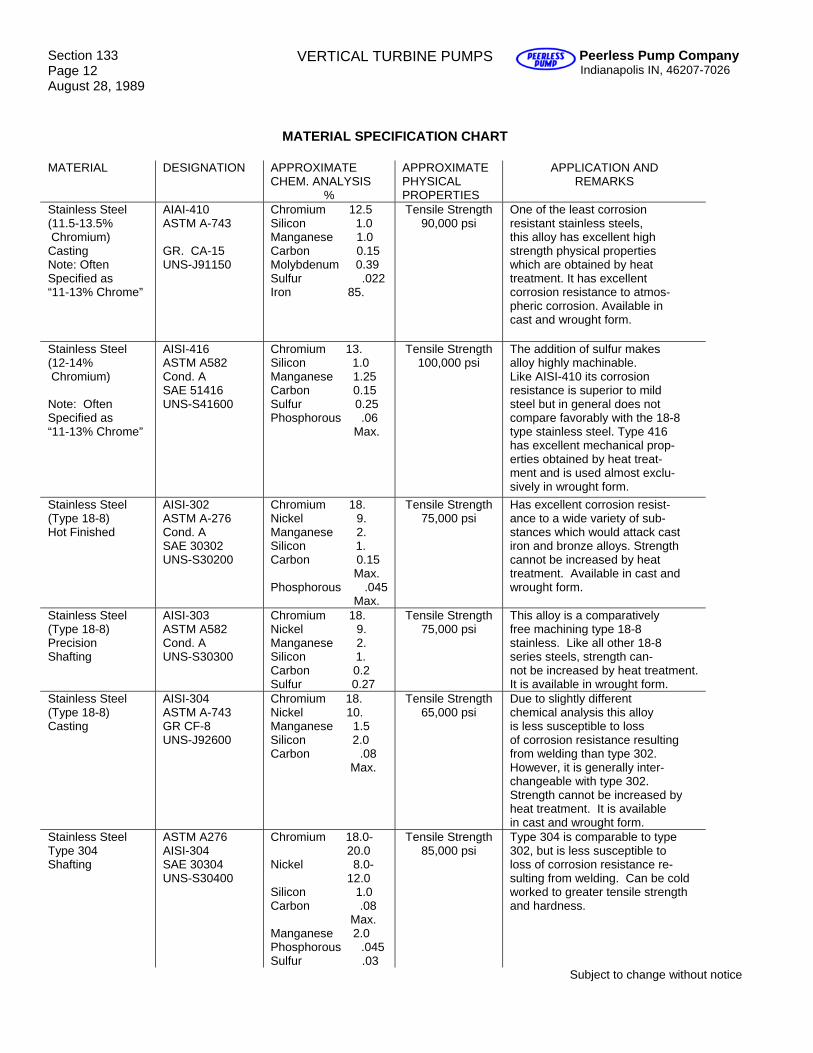
Section 133 Page 12 August 28, 1989
VERTICAL TURBINE PUMPS Peerless Pump Company Indianapolis IN, 46207-7026
MATERIAL SPECIFICATION CHART
MATERIAL DESIGNATION APPROXIMATE CHEM. ANALYSIS
%
APPROXIMATE PHYSICAL PROPERTIES
APPLICATION AND REMARKS
Stainless Steel (11.5-13.5% Chromium) Casting Note: Often Specified as “11-13% Chrome”
AIAI-410 ASTM A-743 GR. CA-15 UNS-J91150
Chromium 12.5 Silicon 1.0 Manganese 1.0 Carbon 0.15 Molybdenum 0.39 Sulfur .022 Iron 85.
Tensile Strength 90,000 psi
One of the least corrosion resistant stainless steels, this alloy has excellent high strength physical properties which are obtained by heat treatment. It has excellent corrosion resistance to atmos- pheric corrosion. Available in cast and wrought form.
Stainless Steel (12-14% Chromium) Note: Often Specified as “11-13% Chrome”
AISI-416 ASTM A582 Cond. A SAE 51416 UNS-S41600
Chromium 13. Silicon 1.0 Manganese 1.25 Carbon 0.15 Sulfur 0.25 Phosphorous .06 Max.
Tensile Strength 100,000 psi
The addition of sulfur makes alloy highly machinable. Like AISI-410 its corrosion resistance is superior to mild steel but in general does not compare favorably with the 18-8 type stainless steel. Type 416 has excellent mechanical prop- erties obtained by heat treat- ment and is used almost exclu- sively in wrought form.
Stainless Steel (Type 18-8) Hot Finished
AISI-302 ASTM A-276 Cond. A SAE 30302 UNS-S30200
Chromium 18. Nickel 9. Manganese 2. Silicon 1. Carbon 0.15 Max. Phosphorous .045 Max.
Tensile Strength 75,000 psi
Has excellent corrosion resist- ance to a wide variety of sub- stances which would attack cast iron and bronze alloys. Strength cannot be increased by heat treatment. Available in cast and wrought form.
Stainless Steel (Type 18-8) Precision Shafting
AISI-303 ASTM A582 Cond. A UNS-S30300
Chromium 18. Nickel 9. Manganese 2. Silicon 1. Carbon 0.2 Sulfur 0.27
Tensile Strength 75,000 psi
This alloy is a comparatively free machining type 18-8 stainless. Like all other 18-8 series steels, strength can- not be increased by heat treatment. It is available in wrought form.
Stainless Steel (Type 18-8) Casting
AISI-304 ASTM A-743 GR CF-8 UNS-J92600
Chromium 18. Nickel 10. Manganese 1.5 Silicon 2.0 Carbon .08 Max.
Tensile Strength 65,000 psi
Due to slightly different chemical analysis this alloy is less susceptible to loss of corrosion resistance resulting from welding than type 302. However, it is generally inter- changeable with type 302. Strength cannot be increased by heat treatment. It is available in cast and wrought form.
Stainless Steel Type 304 Shafting
ASTM A276 AISI-304 SAE 30304 UNS-S30400
Chromium 18.0- 20.0 Nickel 8.0- 12.0 Silicon 1.0 Carbon .08 Max. Manganese 2.0 Phosphorous .045 Sulfur .03
Tensile Strength 85,000 psi
Type 304 is comparable to type 302, but is less susceptible to loss of corrosion resistance re- sulting from welding. Can be cold worked to greater tensile strength and hardness.
Subject to change without notice
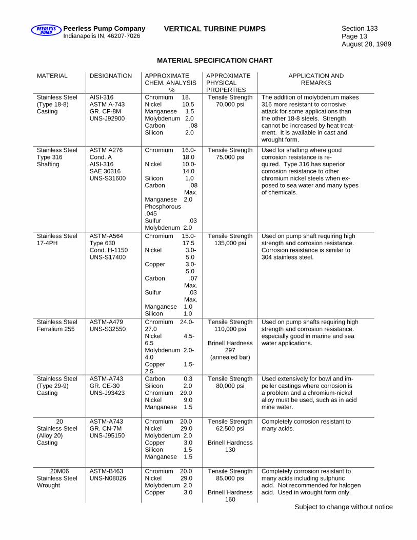
Peerless Pump Company Indianapolis IN, 46207-7026
VERTICAL TURBINE PUMPS Section 133 Page 13 August 28, 1989
MATERIAL SPECIFICATION CHART
MATERIAL DESIGNATION APPROXIMATE
CHEM. ANALYSIS %
APPROXIMATE PHYSICAL PROPERTIES
APPLICATION AND REMARKS
Stainless Steel (Type 18-8) Casting
AISI-316 ASTM A-743 GR. CF-8M UNS-J92900
Chromium 18. Nickel 10.5 Manganese 1.5 Molybdenum 2.0 Carbon .08 Silicon 2.0
Tensile Strength 70,000 psi
The addition of molybdenum makes 316 more resistant to corrosive attack for some applications than the other 18-8 steels. Strength cannot be increased by heat treat- ment. It is available in cast and wrought form.
Stainless Steel Type 316 Shafting
ASTM A276 Cond. A AISI-316 SAE 30316 UNS-S31600
Chromium 16.0- 18.0 Nickel 10.0- 14.0 Silicon 1.0 Carbon .08 Max. Manganese 2.0 Phosphorous .045 Sulfur .03 Molybdenum 2.0
Tensile Strength 75,000 psi
Used for shafting where good corrosion resistance is re- quired. Type 316 has superior corrosion resistance to other chromium nickel steels when ex- posed to sea water and many types of chemicals.
Stainless Steel 17-4PH
ASTM-A564 Type 630 Cond. H-1150 UNS-S17400
Chromium 15.0- 17.5 Nickel 3.0- 5.0 Copper 3.0- 5.0 Carbon .07 Max. Sulfur .03 Max. Manganese 1.0 Silicon 1.0
Tensile Strength 135,000 psi
Used on pump shaft requiring high strength and corrosion resistance. Corrosion resistance is similar to 304 stainless steel.
Stainless Steel Ferralium 255
ASTM-A479 UNS-S32550
Chromium 24.0-27.0 Nickel 4.5- 6.5 Molybdenum 2.0- 4.0 Copper 1.5- 2.5
Tensile Strength 110,000 psi
Brinell Hardness
297 (annealed bar)
Used on pump shafts requiring high strength and corrosion resistance. especially good in marine and sea water applications.
Stainless Steel (Type 29-9) Casting
ASTM-A743 GR. CE-30 UNS-J93423
Carbon 0.3 Silicon 2.0 Chromium 29.0 Nickel 9.0 Manganese 1.5
Tensile Strength 80,000 psi
Used extensively for bowl and im- peller castings where corrosion is a problem and a chromium-nickel alloy must be used, such as in acid mine water.
20 Stainless Steel (Alloy 20) Casting
ASTM-A743 GR. CN-7M UNS-J95150
Chromium 20.0 Nickel 29.0 Molybdenum 2.0 Copper 3.0 Silicon 1.5 Manganese 1.5
Tensile Strength 62,500 psi
Brinell Hardness
130
Completely corrosion resistant to many acids.
20M06 Stainless Steel Wrought
ASTM-B463 UNS-N08026
Chromium 20.0 Nickel 29.0 Molybdenum 2.0 Copper 3.0
Tensile Strength 85,000 psi
Brinell Hardness
160
Completely corrosion resistant to many acids including sulphuric acid. Not recommended for halogen acid. Used in wrought form only.
Subject to change without notice
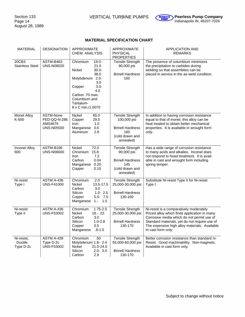
Section 133 Page 14 August 28, 1989
VERTICAL TURBINE PUMPS Peerless Pump Company Indianapolis IN, 46207-7026
MATERIAL SPECIFICATION CHART
MATERIAL DESIGNATION APPROXIMATE CHEM. ANALYSIS
APPROXIMATE PHYSICAL PROPERTIES
APPLICATION AND REMARKS
20CB3 Stainless Steel
ASTM-B463 UNS-N08020
Chromium 19.0- 21.0 Nickel 30.0- 38.0 Molybdenum 2.0- 3.0 Copper 3.0- 4.0 Carbon .70 max. Columbium and Tantalum- 8 x C min./1.0070
Tensile Strength 90,000 psi
Brinell Hardness
160
The presence of columbium minimizes the precipitation to carbides during welding so that assemblies can be placed in service in the as-weld condition.
Monel Alloy K-500
ASTM-None FED-QQ-N-286 AMS4676 UNS-N05500
Nickel 65.0 Copper 29.5 Iron 1.0 Manganese 0.6 Aluminum 2.8
Tensile Strength 100,000 psi
Brinell Hardness
160 (cold drawn and
annealed)
In addition to having corrosion resistance equal to that of monel, this alloy can be heat treated to obtain better mechanical properties. It is available in wrought form only.
Inconel Alloy 600
ASTM-B166 UNS-N06600
Nickel 72.0 Chromium 15.8 Iron 7.2 Carbon 0.04 Manganese 0.20 Copper 0.10
Tensile Strength 90,000 psi
Brinell Hardness
145 (cold drawn and
annealed)
Has a wide range of corrosion resistance to many acids and alkalies. Inconel does not respond to head treatment. It is avail- able in cast and wrought form including spring temper.
Ni-resist Type I
ASTM A-436 UNS-F41000
Chromium 2.0 Nickel 13.5-17.5 Carbon 3.0 Silicon 1.0- 2.5 Copper 5.5- 7.5 Manganese 1.- 1.5
Tensile Strength 25,000-30,000 psi
Brinell Hardness
130-160
Substitute Ni-resist Type II for Ni-resist Type I.
Ni-resist Type II
ASTM A-436 UNS-F53002
Chromium 1.75-2.5 Nickel 18.- 22. Carbon 3.0 Silicon 1.0-2.8 Copper 0.5 Manganese .8-1.5
Tensile Strength 25,000-30,000 psi
Brinell Hardness
130-170
Ni-resist is a comparatively moderately Priced alloy which finds application in many Corrosive media which do not permit use of Standard materials, yet do not require use of The expensive high alloy materials. Available In cast form only.
Ni-resist, Ductile Type D-2c
ASTM A-439 Type D-2c UNS-F53002
Chromium .50 Molybdenum 1.8- 2.4 Nickel 21.0-24.0 Silicon 2.0- 3.0 Carbon 2.9
Tensile Strength 55,000-60,000 psi
Brinell Hardness
130-170
Better corrosion resistance than standard ni- Resist. Good machinability. Non-magnetic. Available in cast form only.
Subject to change without notice
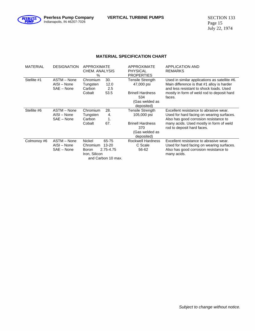
Peerless Pump Company Indianapolis, IN 46207-7026
VERTICAL TURBINE PUMPS SECTION 133 Page 15 July 22, 1974
MATERIAL SPECIFICATION CHART
MATERIAL DESIGNATION APPROXIMATE CHEM. ANALYSIS %
APPROXIMATE PHYSICAL PROPERTIES
APPLICATION AND REMARKS
Stellite #1 ASTM – None AISI – None SAE – None
Chromium 30. Tungsten 12.0 Carbon 2.5 Cobalt 53.5
Tensile Strength 47,000 psi Brinell Hardness 534 (Gas welded as deposited)
Used in similar applications as satellite #6. Main difference is that #1 alloy is harder and less resistant to shock loads. Used mostly in form of weld rod to deposit hard faces.
Stellite #6 ASTM – None AISI – None SAE – None
Chromium 28. Tungsten 4. Carbon 1. Cobalt 67.
Tensile Strength 105,000 psi Brinell Hardness 370 (Gas welded as deposited)
Excellent resistance to abrasive wear. Used for hard facing on wearing surfaces. Also has good corrosion resistance to many acids. Used mostly in form of weld rod to deposit hard faces.
Colmonoy #6 ASTM – None AISI – None SAE – None
Nickel 65-75 Chromium 13-20 Boron 2.75-4.75 Iron, Silicon and Carbon 10 max.
Rockwell Hardness C Scale 56-62
Excellent resistance to abrasive wear. Used for hard facing on wearing surfaces. Also has good corrosion resistance to many acids.
Subject to change without notice.
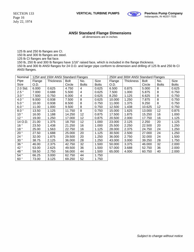
SECTION 133 Page 16 July 22, 1974
VERTICAL TURBINE PUMPS Peerless Pump Company Indianapolis, IN 46207-7026
ANSI Standard Flange Dimensions all dimensions are in inches
125 lb and 250 lb flanges are CI. 150 lb and 300 lb flanges are steel. 125 lb CI flanges are flat face. 150 lb, 250 lb and 300 lb flanges have 1/16” raised face, which is included in the flange thickness. 150 lb and 300 lb ANSI flanges for 24 O.D. and larger pipe conform to dimension and drilling of 125 lb and 250 lb CI ANSI flanges.
125# and 150# ANSI Standard Flanges 250# and 300# ANSI Standard Flanges Nominal Pipe Size
Flange O.D.
Thickness Bolt Circle
No. Bolts
Size Bolts
Flange O.D.
Thickness Bolt Circle
No. Bolts
Size Bolts
2.0 Std. 2.5 “ 3.0 “
6.000 7.000 7.500
0.625 0.688 0.750
4.750 5.500 6.000
4 4 4
0.625 0.625 0.625
6.500 7.500 8.250
0.875 1.000 1.125
5.000 5.875 6.625
8 8 8
0.625 0.750 0.750
4.0 “ 5.0 “ 6.0 “
9.000 10.00 11.00
0.938 0.938 1.000
7.500 8.500 9.500
8 8 8
0.625 0.750 0.750
10.000 11.000 12.500
1.250 1.375 1.438
7.875 9.250 10.625
8 8 12
0.750 0.750 0.750
8.0 “ 10 “ 12 “
13.50 16.00 19.00
1.125 1.188 1.250
11.750 14.250 17.000
8 12 12
0.750 0.875 0.875
15.000 17.500 20.500
1.625 1.875 2.000
13.000 15.250 17.750
12 16 16
0.875 1.000 1.125
14 O.D. 16 “ 18 “
21.00 23.50 25.00
1.375 1.438 1.563
18.750 21.250 22.750
12 16 16
1.000 1.000 1.125
23.000 25.500 28.000
2.125 2.250 2.375
2.250 22.500 24.750
20 20 24
1.125 1.250 1.250
20 “ 24 “ 30 “
27.50 32.00 38.75
1.688 1.875 2.125
25.000 29.500 36.000
20 20 28
1.125 1.250 1.250
30.500 36.000 43.000
2.500 2.750 3.000
27.000 32.000 39.250
24 24 28
1.250 1.500 1.750
36 “ 42 “ 48 “
46.00 53.00 59.50
2.375 2.625 2.750
42.750 49.500 56.000
32 36 44
1.500 1.500 1.500
50.000 57.000 65.000
3.375 3.688 4.000
46.000 52.750 60.750
32 36 40
2.000 2.000 2.000
54 “ 60 “
66.25 73.00
3.000 3.125
62.750 69.250
44 52
1.750 1.750
Subject to change without notice
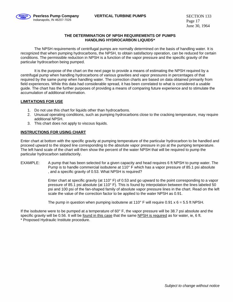
Peerless Pump Company Indianapolis, IN 46207-7026
VERTICAL TURBINE PUMPS SECTION 133 Page 17 June 30, 1964
THE DETERMINATION OF NPSH REQUIREMENTS OF PUMPS
HANDLING HYDROCARBON LIQUIDS* The NPSH requirements of centrifugal pumps are normally determined on the basis of handling water. It is recognized that when pumping hydrocarbons, the NPSH, to obtain satisfactory operation, can be reduced for certain conditions. The permissible reduction in NPSH is a function of the vapor pressure and the specific gravity of the particular hydrocarbon being pumped. It is the purpose of the chart on the next page to provide a means of estimating the NPSH required by a centrifugal pump when handling hydrocarbons of various gravities and vapor pressures in percentages of that required by the same pump when handling water. The correction charts are based on data obtained primarily from field experiences. While this data had considerable spread, it has been correlated to what is considered a usable guide. The chart has the further purposes of providing a means of comparing future experience and to stimulate the accumulation of additional information. LIMITATIONS FOR USE
1. Do not use this chart for liquids other than hydrocarbons. 2. Unusual operating conditions, such as pumping hydrocarbons close to the cracking temperature, may require
additional NPSH. 3. This chart does not apply to viscous liquids.
INSTRUCTIONS FOR USING CHART Enter chart at bottom with the specific gravity at pumping temperature of the particular hydrocarbon to be handled and proceed upward to the sloped line corresponding to the absolute vapor pressure in psi at the pumping temperature. The left hand scale of the chart will then show the percent of the water NPSH that will be required to pump the particular hydrocarbon satisfactorily. EXAMPLE: A pump that has been selected for a given capacity and head requires 6 ft NPSH to pump water. The Pump is to handle commercial isobutene at 110° F which has a vapor pressure of 85.1 psi absolute , and a specific gravity of 0.53. What NPSH is required? Enter chart at specific gravity (at 110° F) of 0.53 and go upward to the point corresponding to a vapor
pressure of 85.1 psi absolute (at 110° F). This is found by interpolation between the lines labeled 50 psi and 100 psi of the fan-shaped family of absolute vapor pressure lines in the chart. Read on the left scale the value of the correction factor to be applied to the water NPSH as 0.91. The pump in question when pumping isobutene at 110° F will require 0.91 x 6 = 5.5 ft NPSH.
If the isobutene were to be pumped at a temperature of 60° F, the vapor pressure will be 38.7 psi absolute and the specific gravity will be 0.56. It will be found in this case that the same NPSH is required as for water, ie, 6 ft. * Proposed Hydraulic Institute procedure.
Subject to change without notice
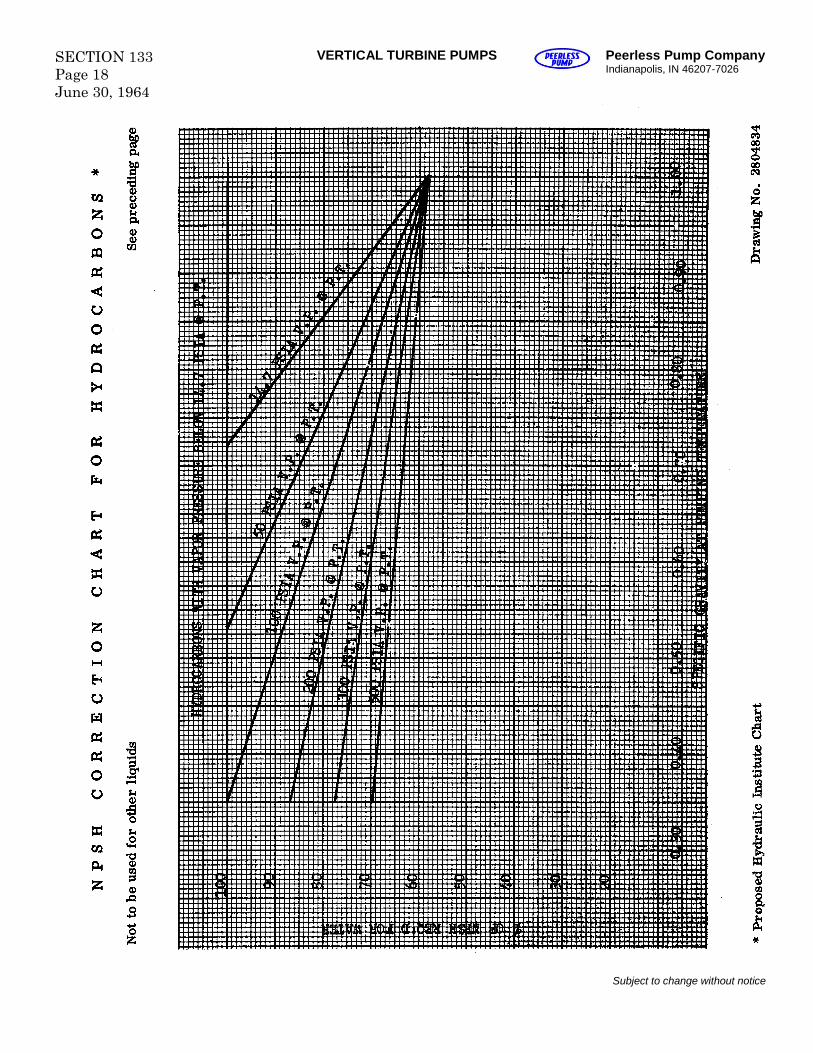
SECTION 133Page 18June 30, 1964
VERTICAL TURBINE PUMPS Peerless Pump CompanyIndianapolis, IN 46207-7026
Subject to change without notice
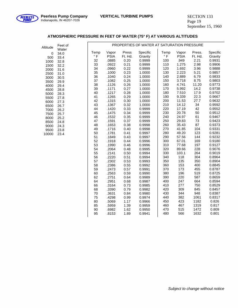
Peerless Pump Company Indianapolis, IN 46207-7026
VERTICAL TURBINE PUMPS SECTION 133 Page 19 September 15, 1960
ATMOSPHERIC PRESSURE IN FEET OF WATER (75° F) AT VARIOUS ALTITUDES
PROPERTIES OF WATER AT SATURATION PRESSURE
Temp ° F
Vapor PSIA
Press Ft. Hd.
Specific Gravity
32 33 34 35
.0885
.0922
.0960
.1000
0.20 0.21 0.22 0.23
0.9999 0.9999 0.9999 1.0000
36 37 38 39 40
.1040
.1082
.1126
.1171
.1217
0.24 0.25 0.26 0.27 0.28
1.0000 1.0000 1.0000 1.0000 1.0000
41 42 43 44 45
.1265
.1315
.1367
.1420
.1475
0.29 0.30 0.32 0.33 0.34
1.0000 1.0000 1.0000 0.9999 0.9999
46 47 48 49 50
.1532
.1591
.1653
.1716
.1781
0.35 0.37 0.38 0.40 0.41
0.9999 0.9999 0.9998 0.9998 0.9997
51 52 53 54 55
.1849
.1918
.1990
.2064
.2141
0.43 0.44 0.46 0.48 0.50
0.9997 0.9996 0.9996 0.9995 0.9994
56 57 58 59 60
.2220
.2302
.2386
.2473
.2563
0.51 0.53 0.55 0.57 0.59
0.9994 0.9993 0.9992 0.9991 0.9990
62 64 66 68 70
.2751
.2951
.3164
.3390
.3631
0.64 0.68 0.73 0.79 0.84
0.9989 0.9987 0.9985 0.9982 0.9980
75 80 85 90 95
.4298
.5069
.5959
.6982
.8153
0.99 1.17 1.39 1.62 1.89
0.9974 0.9966 0.9959 0.9950 0.9941
Temp ° F
Vapor PSIA
Press. Ft. Hd.
Specific Gravity
100 110 120 130 140
.949 1.275 1.692 2.223 2.889
2.21 2.98 3.96 5.21 6.79
0.9931 0.9906 0.9888 0.9857 0.9833
150 160 170 180 190
3.718 4.741 5.992 7.510 9.339
8.75 11.20 14.2 17.9 22.3
0.9803 0.9773 0.9738 0.9702 0.9667
200 210 220 230 240
11.53 14.12 17.19 20.78 24.97
27.7 34 42 50 61
0.9632 0.9592 0.9552 0.9512 0.9467
250 260 270 280 290
29.83 35.43 41.85 49.20 57.56
73 87
104 123 144
0.9423 0.9373 0.9331 0.9281 0.9232
300 310 320 330 340
67.01 77.68 89.66 103.1 118
169 197 228 264 304
0.9180 0.9127 0.9076 0.9019 0.8964
350 360 370 380 390
135 153 173 196 220
350 400 455 519 587
0.8904 0.8845 0.8787 0.8725 0.8659
400 410 420 430 440
247 277 309 344 382
664 750 845 948
1061
0.8594 0.8529 0.8457 0.8387 0.8317
450 460 470 480
423 467 515 566
1182 1319 1472 1632
0.826 0.817 0.809 0.801
Altitude Feet of Water
0 500
1000 1500 2000 2500 3000 3500 4000 4500 5000 5500 6000 6500 7000 7500 8000 8500 9000 9500
10000
34.0 33.4 32.8 32.2 31.6 31.0 30.5 29.9 29.4 28.8 28.3 27.8 27.3 26.7 26.2 25.7 25.2 24.8 24.3 23.8 23.4
Subject to change without notice
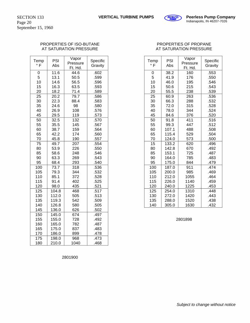
SECTION 133 Page 20 September 15, 1960
VERTICAL TURBINE PUMPS Peerless Pump Company Indianapolis, IN 46207-7026
PROPERTIES OF PROPANE AT SATURATION PRESSURE
Temp ° F
PSI Abs
Vapor Pressure Ft. Hd.
Specific Gravity
0 5 10 15 20
38.2 41.9 46.0 50.6 55.5
160 176 195 215 238
.553
.550
.546
.543
.539 25 30 35 40 45
60.9 66.3 72.0 78.0 84.6
263 288 315 344 376
.536
.532
.528
.524
.520 50 55 60 65 70
91.8 99.3 107.1 115.4 124.0
411 447 488 529 573
.516
.512
.508
.504
.500 15 80 85 90 95
133.2 142.8 153.1 164.0 175.0
620 670 725 785 844
.496
.492
.487
.483
.479 100 105 110 115 120
187.0 200.0 212.0 226.0 240.0
911 985
1055 1140 1225
.474
.469
.464
.459
.453 125 130 135 140
254.0 272.0 288.0 305.0
1310 1420 1520 1630
.448
.443
.438
.432
2801898
PROPERTIES OF ISO-BUTANE AT SATURATION PRESSURE
Temp ° F
PSI Abs
Vapor Pressure Ft. Hd.
Specific Gravity
0 5 10 15 20
11.6 13.1 14.6 16.3 18.2
44.6 50.5 56.5 63.5 71.4
.602
.599
.596
.593
.589 25 30 35 40 45
20.2 22.3 24.6 26.9 29.5
79.7 88.4 98 108 119
.586
.583
.580
.576
.573 50 55 60 65 70
32.5 35.5 38.7 42.2 45.8
132 145 159 174 190
.570
.567
.564
.560
.557 75 80 85 90 95
49.7 53.9 58.6 63.3 68.4
207 226 248 269 293
.554
.550
.546
.543
.540 100 105 110 115 120
73.7 79.3 85.1 91.4 98.0
318 344 372 402 435
.536
.532
.528
.525
.521 125 130 135 140 145
104.8 112.0 119.3 126.8 136.0
468 505 542 580 626
.517
.513
.509
.505
.502 150 155 160 165 170
145.0 155.0 165.0 175.0 186.0
674 728 782 837 899
.497
.492
.487
.483
.478 175 180
198.0 210.0
968 1040
.473
.468
2801900
Subject to change without notice
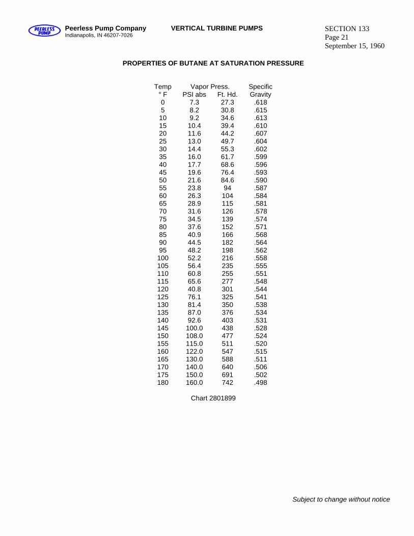
Peerless Pump Company Indianapolis, IN 46207-7026
VERTICAL TURBINE PUMPS SECTION 133 Page 21 September 15, 1960
PROPERTIES OF BUTANE AT SATURATION PRESSURE
Vapor Press. Temp ° F PSI abs Ft. Hd.
Specific Gravity
0 5 10 15 20
7.3 8.2 9.2 10.4 11.6
27.3 30.8 34.6 39.4 44.2
.618
.615
.613
.610
.607 25 30 35 40 45
13.0 14.4 16.0 17.7 19.6
49.7 55.3 61.7 68.6 76.4
.604
.602
.599
.596
.593 50 55 60 65 70
21.6 23.8 26.3 28.9 31.6
84.6 94 104 115 126
.590
.587
.584
.581
.578 75 80 85 90 95
34.5 37.6 40.9 44.5 48.2
139 152 166 182 198
.574
.571
.568
.564
.562 100 105 110 115 120
52.2 56.4 60.8 65.6 40.8
216 235 255 277 301
.558
.555
.551
.548
.544 125 130 135 140 145
76.1 81.4 87.0 92.6
100.0
325 350 376 403 438
.541
.538
.534
.531
.528 150 155 160 165 170
108.0 115.0 122.0 130.0 140.0
477 511 547 588 640
.524
.520
.515
.511
.506 175 180
150.0 160.0
691 742
.502
.498
Chart 2801899
Subject to change without notice

Blank
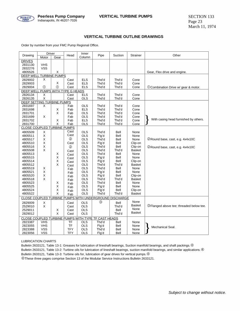
Peerless Pump CompanyIndianapolis, IN 46207-7026
VERTICAL TURBINE PUMPS SECTION 133Page 23March 11, 1974
VERTICAL TURBINE OUTLINE DRAWINGS
Order by number from your FMC Pump Regional Office.
DriverDrawingMotor Gear
Head InnerColumn Pipe Suction Strainer Other
DRIVES283113028322764805526
VHSVSS
X Gear, Flex drive and engine.DEEP WELL TURBINE PUMPS282900228290032829004
X
X
CastCastCast
ELSELSELS
Thd’dThd’dThd’d
Thd’dThd’dThd’d
ConeConeCone Combination Drive w/ gear & motor.
DEEP WELL PUMPS WITH TYPE G HEADS28261342826135
XX
CastCast
ELSOLS
Thd’dThd’d
Thd’dThd’d
ConeCone
DEEP SETTING TURBINE PUMPS283169728316982831701283169928317022831700
X
X
XX
XX
FabFabFabFabFabFab
OLSELSOLSOLSELSOLS
Thd’dThd’dThd’dThd’dThd’dThd’d
Thd’dThd’dThd’dThd’dThd’dThd’d
ConeConeConeConeConeCone
CLOSE COUPLED TURBINE PUMPS480550948055114805517480551048055164805508480551348055154805514480551248055194805521480552048055184805523480552548055244805522
XXXXXX
XXXX
XXXX
XXXX
CastCast
Cast
CastCastCastCastCastFabFabFabFabFabFabFabFab
OLSOLSOLSOLSOLSOLSOLSOLSOLSOLSOLSOLSOLSOLSOLSOLSOLSOLS
Thd’dFlg’dThd’dFlg’dThd’dThd’dThd’dFlg’dFlg’dThd’dThd’dFlg’dFlg’dThd’dThd’dFlg’dFlg’dThd’d
BellBellBellBellBellThd’dBellBellBellThd’dBellBellBellThd’dBellBellBellThd’d
NoneNoneNone
Clip-onClip-onBasketNoneNone
Clip-onBasketNoneNone
Clip-onBasketNoneNone
Clip-onBasket
Round base, cast, e.g. 4x4x10C
Round base, cast, e.g. 4x4x10C
CLOSE COUPLED TURBINE PUMPS WITH UNDERGROUND DISCHARGE2829009252901025290112829012
XX
XX
CastCastCastCast
OLSOLSOLSOLS
BellThd’dBellThd’d
NoneBasketNone
Basket
Flanged above tee; threaded below tee.
CLOSE COUPLED TURBINE PUMPS WITH TYPE TF CAST HEADS2823387282305528233882823056
VHSVHSVSSVSS
TFTF
TFYTFY
OLSOLSOLSOLS
Thd’dFlg’dThd’dFlg’d
BellBellBellBell
NoneNoneNoneNone
LUBRICATION CHARTSBulletin 2633121, Table 13-1: Greases for lubrication of lineshaft bearings, Suction manifold bearings, and shaft packings.Bulletin 2633121, Table 13-2: Turbine oils for lubrication of lineshaft bearings, suction manifold bearings, and similar applications.Bulletin 2633121, Table 13-3: Turbine oils for, lubrication of gear drives for vertical pumps.These three pages comprise Section 13 of the Modular Service Instructions Bulletin 2633121.
Subject to change without notice.
} Mechanical Seal.
With casing head furnished by others.}

Blank
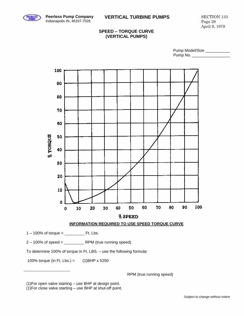
Peerless Pump CompanyIndianapolis IN, 46207-7026
VERTICAL TURBINE PUMPS SECTION 133Page 29April 9, 1979
SPEED –TORQUE CURVE(VERTICAL PUMPS)
Pump Model/Size ___________Pump No. _________________
INFORMATION REQUIRED TO USE SPEED TORQUE CURVE
1 –100% of torque = _________ Ft. Lbs.
2 –100% of speed = _________ RPM (true running speed)
To determine 100% of torque in Ft. LBS. –use the following formula:
100% torque (in Ft. Lbs.) = (1)BHP x 5250
RPM (true running speed)
(1)For open valve starting –use BHP at design point.(1)For close valve starting –use BHP at shut-off point.
Subject to change without notice
SECTION 133Page 30April 9, 1979
VERTICAL TURBINE PUMPS Peerless Pump CompanyIndianapolis, IN 46207-7026
POLICY ON SUMP DESIGN RECOMMENDATION
WITHOUT ANY GUARANTEE, ASSUMED OR IMPLIED, PEERLESS PUMP WILL COMMENT, WITHOUT CHARGE,ON PROPOSED OR EXISTING SUMP DESIGNS. THESE COMMENTS WILL BE BASED ON ADEQUATECUSTOMER-FURNISHED DATA, AND WILL REFLECT PEERLESS PUMP’S EXPERIENCE AND JUDGEMENT, AS WELL AS INFORMATION FROM OTHER QUALIFIED SOURCES.
PEERLESS PUMP WILL NOT GUARANTEE ANY SUMP DESIGN OR SUMP CONFIGURATION. WHEREDETAILED SCALE MODEL TESTS ARE CONDUCTED IN PEERLESS PUMP’S HYDRAULIC LABORATORY, A SOUND BASIS FOR FULL-SCALE SUMP PERFORMANCE PREDICTION IS AVAILABLE TO THE CUSTOMER.
PEERLESS PUMP CAN COMMENT ON HYDRAULIC DESIGNS ONLY. NO COMMENT ON STRUCTURALDESIGN WILL BE MADE.
SUPERSEDES PREVIOUSPUBLICATIONS.
Subject to change without notice.
Peerless Pump Company Indianapolis, IN 46207-7026
VERTICAL TURBINE PUMPS SECTION 133 Page 31 October 31, 1972
SUMP DESIGN DATA
“SECTOIN 133, PAGES 31 THRU 38 REPRINTED FROM HYDRAULIC INSTITUTE STANDARDS, TWELFTH EDITION, COPYRIGHT 1969 BY HYDRAULIC INSTITUTE, 122 EAST 42ND STREET, NEW YORK, NEW YORK, 10017.” Note: The following information has to do with vortexing and eddy formation only and does not imply sufficient submergence to meet other requirements such as NPSH. Intake Design The function of the intake, whether it be an open channel or a tunnel having 100 percent wetted perimeter, is to supply an evenly distributed flow of water to the suction bell. An uneven distribution of flow, characterized by strong local currents, favors formation of vortices and with certain low values of submergence, will introduce air into the pump with reduction of capacity, accompanied by noise. Uneven distribution can also increase or decrease the power consumption with a change in total developed head. There can be vortices which do not appear on the surface, and these also may have adverse effects. Uneven velocity distribution leads to rotation of portions of the mass of water about a centerline called vortex motion. This centerline may also be moving. Uneven distribution of flow is caused by the geometry of the intake and the manner in which water is introduced into the intake from the primary source. Calculated low average velocity is not always a proper basis for judging the excellence of an intake. High local velocities in currents and in swirls may be present in intakes which have very low average velocity. Indeed, the uneven distribution which they represent occurs less in a higher velocity flow with sufficient turbulence to discourage the gradual build-up of a larger and larger vortex in any region. Numbers of small surface eddies may be present without causing any trouble. The ideal approach is a straight channel coming directly to the pump. Turns and obstructions are detrimental since they may cause eddy currents and tend to initiate deep-cored vortices. Water should not flow past one pump to reach the next if this can be avoided. If the pumps must be in the line of flow, it may prove necessary to construct an open front cell around each pump or to put turning vanes under the pump to deflect the water upward. All possible streamlining should be used to reduce the trail of alternating vortices in the wake of the pump or of other obstructions in the stream flow. Successful proportions of the amount of submergence per se (See Suction Limitations, page 67), will depend greatly on the approaches to the intake and the size of the pump. The pump manufacturer will generally render advice on specific problems while the intake design is still preliminary if he is provided with the necessary intake layout drawings reflecting the physical imitations of the site. Complete analysis of intake structures is best accomplished by scale model tests (See Model Tests of Intakes, page 36).
Subject to the qualifications of the foregoing statements, Figs. 64, 65 & 66 have been constructed for single and simple multiple pump arrangements to show suggestions for basic sump dimensions. They are for pumps normally operating in the capacity range of approximately 3,000 to 300,000 GPM. Since these values are composite averages from a great many pump types and cover the entire range of specific speeds, they must not be thought of as absolute values but rather as basic guides subject to some possible variations. For pumps normally operating at capacities below approximately 3,000 GPM, refer to Sump or Pit Designs (small pumps) page 36. All of the dimensions in Figs. 64, 65 & 66 are based on the rated capacity of the pump at the design head. Any increase in capacity above these values should be momentary or very limited in time. If operation at an increased capacity is to be undertaken for considerable periods of time, the maximum capacity should be used for the design value in obtaining sump dimensions. The Dimension C is an average, based on an analysis of many pumps. Its final value should be specified by the pump manufacturer. Dimension B is a suggested maximum dimension which may be less depending on actual suction bell or bowl diameters in use by the pump manufacturer. The edge of the bell should be close to the back wall of the sump. When the position of the back wall is determined by the driving equipment or the discharge piping, Dimension B may become excessive and a “false” back wall should be installed. Dimension S is a minimum for the sump width for a single pump installation. This dimension can be increased, but if it is to be made smaller, the manufacturer should be consulted or a sump model test should be run to determine its adequacy. Dimension H is a minimum value based on the “normal low water level” at the pump suction bell, taking into consideration friction losses through the inlet screen and approach channel. This dimension can be considerably less momentarily or infrequently without excessive damage to the pump. It should be remembered, however, that this does not represent “submergence.” Submergence is normally quoted as dimension “H” minus “C.” This represents the physical height of water level above the bottom of the suction inlet. The actual submergence of the pump is something less than this, since the impeller eye is some distance above the bottom of the suction bell, possibly as much as 3 to 4 feet. For the purposes of sump design in connection with this chart, it is understood that the pump has been selected in accordance with specific speed charts, Figs. 54,
Subject to change without notice
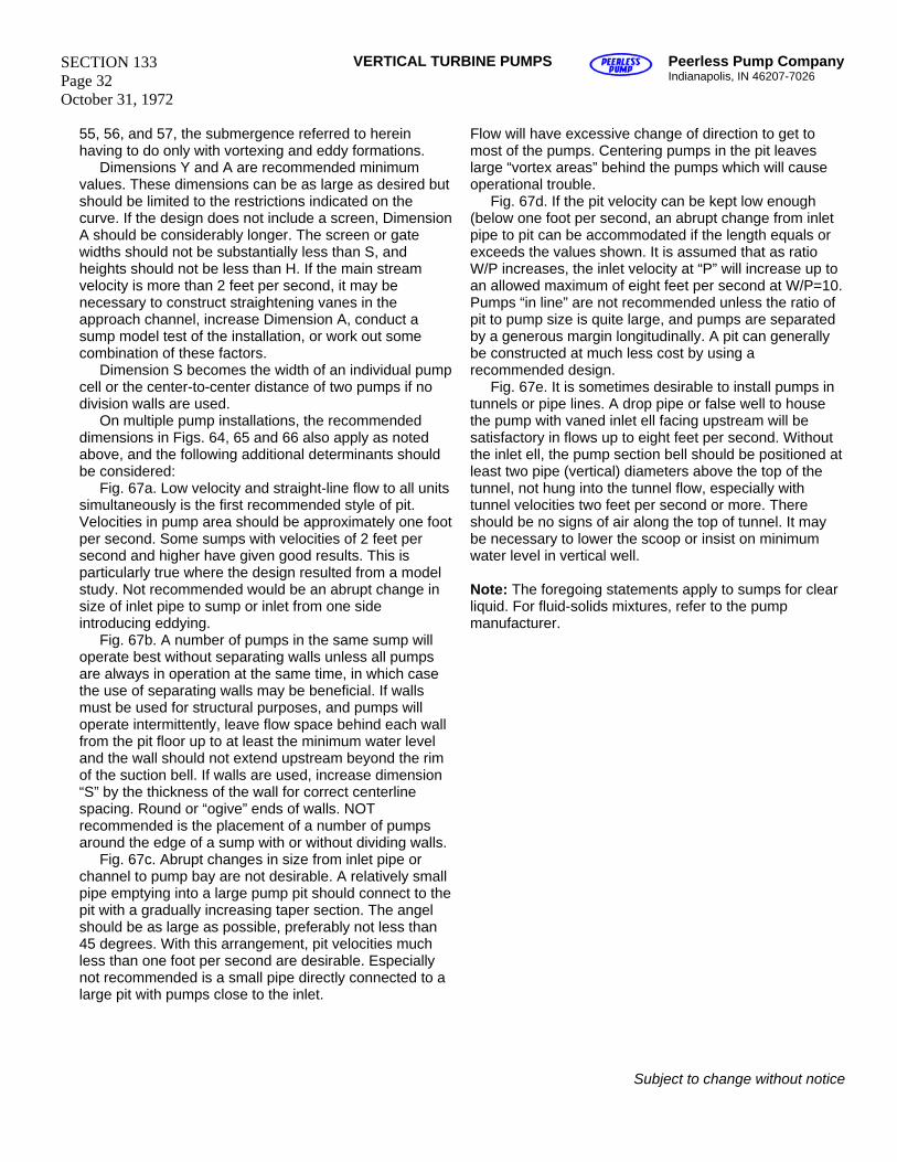
SECTION 133 Page 32 October 31, 1972
VERTICAL TURBINE PUMPS Peerless Pump Company Indianapolis, IN 46207-7026
55, 56, and 57, the submergence referred to herein having to do only with vortexing and eddy formations. Dimensions Y and A are recommended minimum values. These dimensions can be as large as desired but should be limited to the restrictions indicated on the curve. If the design does not include a screen, Dimension A should be considerably longer. The screen or gate widths should not be substantially less than S, and heights should not be less than H. If the main stream velocity is more than 2 feet per second, it may be necessary to construct straightening vanes in the approach channel, increase Dimension A, conduct a sump model test of the installation, or work out some combination of these factors. Dimension S becomes the width of an individual pump cell or the center-to-center distance of two pumps if no division walls are used. On multiple pump installations, the recommended dimensions in Figs. 64, 65 and 66 also apply as noted above, and the following additional determinants should be considered: Fig. 67a. Low velocity and straight-line flow to all units simultaneously is the first recommended style of pit. Velocities in pump area should be approximately one foot per second. Some sumps with velocities of 2 feet per second and higher have given good results. This is particularly true where the design resulted from a model study. Not recommended would be an abrupt change in size of inlet pipe to sump or inlet from one side introducing eddying. Fig. 67b. A number of pumps in the same sump will operate best without separating walls unless all pumps are always in operation at the same time, in which case the use of separating walls may be beneficial. If walls must be used for structural purposes, and pumps will operate intermittently, leave flow space behind each wall from the pit floor up to at least the minimum water level and the wall should not extend upstream beyond the rim of the suction bell. If walls are used, increase dimension “S” by the thickness of the wall for correct centerline spacing. Round or “ogive” ends of walls. NOT recommended is the placement of a number of pumps around the edge of a sump with or without dividing walls. Fig. 67c. Abrupt changes in size from inlet pipe or channel to pump bay are not desirable. A relatively small pipe emptying into a large pump pit should connect to the pit with a gradually increasing taper section. The angel should be as large as possible, preferably not less than 45 degrees. With this arrangement, pit velocities much less than one foot per second are desirable. Especially not recommended is a small pipe directly connected to a large pit with pumps close to the inlet.
Flow will have excessive change of direction to get to most of the pumps. Centering pumps in the pit leaves large “vortex areas” behind the pumps which will cause operational trouble. Fig. 67d. If the pit velocity can be kept low enough (below one foot per second, an abrupt change from inlet pipe to pit can be accommodated if the length equals or exceeds the values shown. It is assumed that as ratio W/P increases, the inlet velocity at “P” will increase up to an allowed maximum of eight feet per second at W/P=10. Pumps “in line” are not recommended unless the ratio of pit to pump size is quite large, and pumps are separated by a generous margin longitudinally. A pit can generally be constructed at much less cost by using a recommended design. Fig. 67e. It is sometimes desirable to install pumps in tunnels or pipe lines. A drop pipe or false well to house the pump with vaned inlet ell facing upstream will be satisfactory in flows up to eight feet per second. Without the inlet ell, the pump section bell should be positioned at least two pipe (vertical) diameters above the top of the tunnel, not hung into the tunnel flow, especially with tunnel velocities two feet per second or more. There should be no signs of air along the top of tunnel. It may be necessary to lower the scoop or insist on minimum water level in vertical well. Note: The foregoing statements apply to sumps for clear liquid. For fluid-solids mixtures, refer to the pump manufacturer.
Subject to change without notice
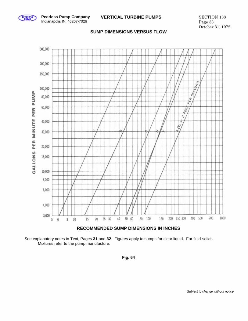
Peerless Pump CompanyIndianapolis IN, 46207-7026
VERTICAL TURBINE PUMPS SECTION 133Page 33October 31, 1972
SUMP DIMENSIONS VERSUS FLOW
RECOMMENDED SUMP DIMENSIONS IN INCHES
See explanatory notes in Text, Pages 31 and 32. Figures apply to sumps for clear liquid. For fluid-solidsMixtures refer to the pump manufacture.
Fig. 64
Subject to change without notice
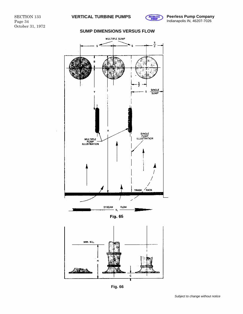
SECTION 133Page 34October 31, 1972
VERTICAL TURBINE PUMPS Peerless Pump CompanyIndianapolis IN, 46207-7026
SUMP DIMENSIONS VERSUS FLOW
Fig. 66
Subject to change without notice
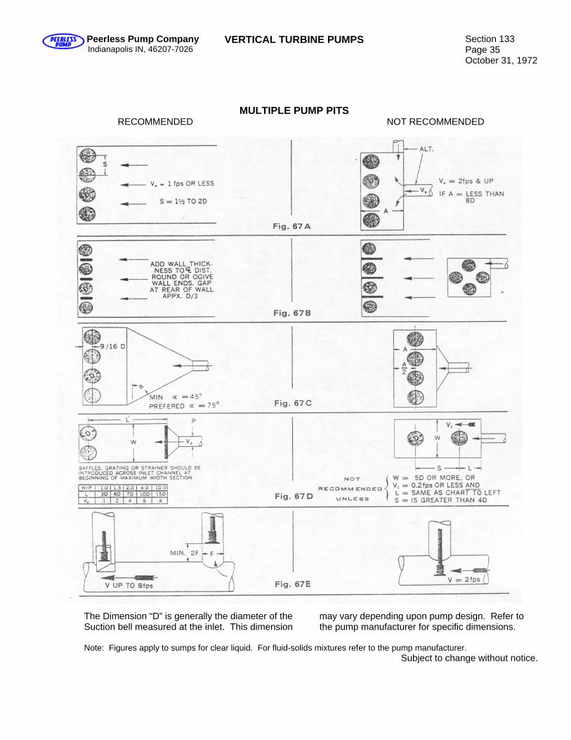
Peerless Pump Company Indianapolis IN, 46207-7026
VERTICAL TURBINE PUMPS Section 133 Page 35 October 31, 1972
MULTIPLE PUMP PITS RECOMMENDED NOT RECOMMENDED
The Dimension “D” is generally the diameter of the may vary depending upon pump design. Refer to Suction bell measured at the inlet. This dimension the pump manufacturer for specific dimensions. Note: Figures apply to sumps for clear liquid. For fluid-solids mixtures refer to the pump manufacturer.
Subject to change without notice.

Section 133 Page 36 October 31, 1972
VERTICAL TURBINE PUMPS Peerless Pump Company Indianapolis IN, 46207-7026
Correction of Existing Sumps It is well established that vortexing in pump suction pits is harmful to pumps and intake structures. It is equally true that a very small force will actually begin generating a vortex. While this phenomenon can be avoided in the new design, for existing structures where problems are already apparent or where expansion is required, corrective measures may be necessary. Possible revisions to correct particular sump problems are shown in Fig. 68. In many cases, field modifications are expensive with no guarantee of success. It is recommended that a sump model test be considered to prove the effectiveness of the proposed changes. Fig. 68a – Reduce inlet velocity by spreading the inflow over a larger area, or change the direction and velocity of inflow by suitable baffling.
1. Floor mounted, extending above the minimum flow level.
2. Hanging, extending alternately close to the floor, close to the minimum flow level.
Fig.68b – Change the location of pumps in relation to the inflow. Fig. 68c – Change the direction of flow by adding splitters to the floor and back wall of pit under centerline of pump.
1. Parallel to inlet flow. 2. Attach to pump bell if floor inaccessible. Fig. 68d – Provide break-thru to “no-
flow” bays in multiple pump pits and round or “ogive” ends of separating walls, or Fig. 68e – Eliminate separating walls. Fig. 68f – Eliminate sharp corners at gates, screens, etc., by filling in for smooth flow contour (fairing).
Subject to change without notice
Fig. 68g – Reduce the velocity of flow and eliminate vortexing by adding bell extension suction plate and splitter to pump bell. Fig. 68h – Use floating rafts around the pump column to prevent surface vortices. Fig. 68I – Use large spheres to prevent surface vortices. Fig. 68j – Improve velocity pattern to the pump to reduce the possibility of vortex formation. Fig. 68k – Change inlet flow direction gradually by means of parallel turning vanes. In general: Keep inlet flow below two feet per second. Keep flow in pit below one foot per second. Avoid changing direction of flow from inlet to pump, or Change direction gradually, smoothly, independently. Any of these alterations, singly or in combination, may help to create a better flow pattern in the sump. If troubles persist, it may be necessary to limit the total flow or change pump size and speed. Model Tests of Intakes
Often the analysis of a proposed intake design can only be use of a scale model of the intake. The engineers responsible for the design of the pumping station should consult with pump manufacturers to establish one or more intake arrangements. A sump model test can then be conducted by a University or by the pump modifications of structure or baffling arrangement to be necessary, and sometimes sump model tests show how considerable savings can be made in the intake structure. The model should be extensive enough to include all parts of the channel likely to affect the flow near the pump, including screens and gates. Deviations may occur between model and prototype, since all considerations of similarity cannot be produced simultaneously. Consequently, the range of levels in velocities to be explored should be as broad as possible in order to disclose any markedly unfavorable tendencies which might only be incipient at mathematically analogous conditions. Comparable flow in the model is generally considered to be obtained at equal Froude numbers. On the basis, Where Vm = velocity of water in the model Vp = velocity of water in the prototype R = linear scale ratio of model to prototype or Lm Lp Where Lm = any linear dimension of the model Lp = the dimensions on the prototype
Corresponding to any dimension Lm = on the model.
Several investigators have found better agreement between model and prototype when velocities are equal, than when velocities are equal, than when velocities are in accord with the Froude number. In the present stage of the art, caution suggests that this entire range of velocities be explored in the model test. Sump or Pit Design (Small Pumps) The design of sumps for small pumps (less than approximately 3,000 gpm normal discharge capacity per pump) should be guided by the same general principles as outlined on pages 31-36. However, since there is a large variety of geometric configurations for these small units, recommended limiting dimensions, such as shown in Fig. 64-66, cannot be sufficiently generalized and
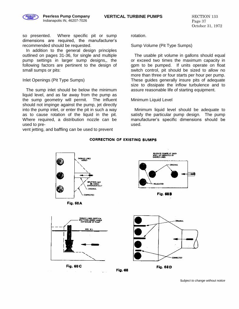
Peerless Pump CompanyIndianapolis IN, 46207-7026
VERTICAL TURBINE PUMPS SECTION 133Page 37October 31, 1972
so presented. Where specific pit or sumpdimensions are required, the manufacturer’s recommended should be requested.
In addition to the general design principlesoutlined on pages 31-36, for single and multiplepump settings in larger sump designs,, thefollowing factors are pertinent to the design ofsmall sumps or pits:
Inlet Openings (Pit Type Sumps)
The sump inlet should be below the minimumliquid level, and as far away from the pump asthe sump geometry will permit. The influentshould not impinge against the pump, jet directlyinto the pump inlet, or enter the pit in such a wayas to cause rotation of the liquid in the pit.Where required, a distribution nozzle can beused to pre-vent jetting, and baffling can be used to prevent
rotation.
Sump Volume (Pit Type Sumps)
The usable pit volume in gallons should equalor exceed two times the maximum capacity ingpm to be pumped. If units operate on floatswitch control, pit should be sized to allow nomore than three or four starts per hour per pump.These guides generally insure pits of adequatesize to dissipate the inflow turbulence and toassure reasonable life of starting equipment.
Minimum Liquid Level
Minimum liquid level should be adequate tosatisfy the particular pump design. The pumpmanufacturer’s specific dimensions should be used.
subject to change without notice
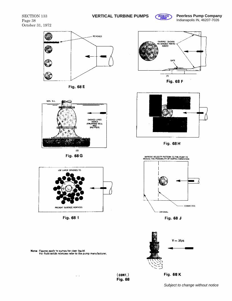
SECTION 133Page 38October 31, 1972
VERTICAL TURBINE PUMPS Peerless Pump CompanyIndianapolis IN, 46207-7026
Subject to change without notice
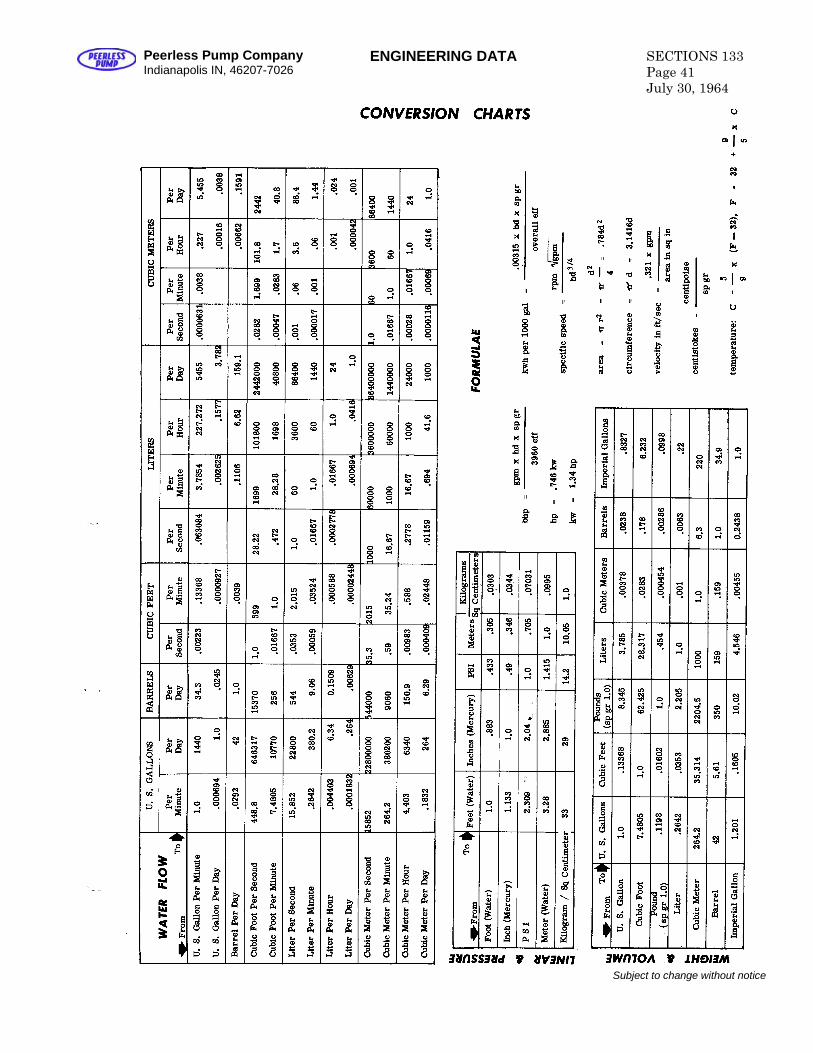
Peerless Pump CompanyIndianapolis IN, 46207-7026
ENGINEERING DATA SECTIONS 133Page 41July 30, 1964
Subject to change without notice

Blank
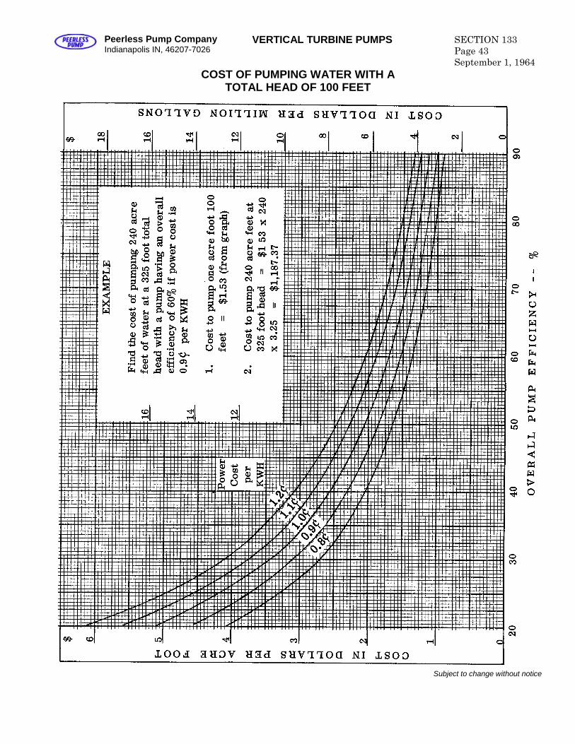
Peerless Pump CompanyIndianapolis IN, 46207-7026
VERTICAL TURBINE PUMPS SECTION 133Page 43September 1, 1964
COST OF PUMPING WATER WITH ATOTAL HEAD OF 100 FEET
Subject to change without notice

Blank
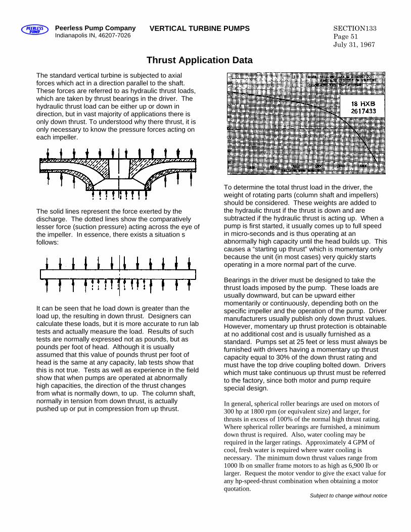
Peerless Pump Compan yIndianapolis IN, 46207-7026 VERTICAL TURBINE PUMPS SECTION133
Page 51 July 31, 1967
Thrust Application Data The standard vertical turbine is subjected to axial forces which act in a direction parallel to the shaft. These forces are referred to as hydraulic thrust loads, which are taken by thrust bearings in the driver. The hydraulic thrust load can be either up or down in direction, but in vast majority of applications there is only down thrust. To understood why there thrust, it is only necessary to know the pressure forces acting on each impeller.
The solid lines represent the force exerted by the discharge. The dotted lines show the comparatively lesser force (suction pressure) acting across the eye of the impeller. In essence, there exists a situation s follows:
It can be seen that he load down is greater than the load up, the resulting in down thrust. Designers can calculate these loads, but it is more accurate to run lab tests and actually measure the load. Results of such tests are normally expressed not as pounds, but as pounds per foot of head. Although it is usually assumed that this value of pounds thrust per foot of head is the same at any capacity, lab tests show that this is not true. Tests as well as experience in the field show that when pumps are operated at abnormally high capacities, the direction of the thrust changes from what is normally down, to up. The column shaft, normally in tension from down thrust, is actually pushed up or put in compression from up thrust.
To determine the total thrust load in the driver, the weight of rotating parts (column shaft and impellers) should be considered. These weights are added to the hydraulic thrust if the thrust is down and are subtracted if the hydraulic thrust is acting up. When a pump is first started, it usually comes up to full speed in micro-seconds and is thus operating at an abnormally high capacity until the head builds up. This causes a “starting up thrust” which is momentary only because the unit (in most cases) very quickly starts operating in a more normal part of the curve. Bearings in the driver must be designed to take the thrust loads imposed by the pump. These loads are usually downward, but can be upward either momentarily or continuously, depending both on the specific impeller and the operation of the pump. Driver manufacturers usually publish only down thrust values. However, momentary up thrust protection is obtainable at no additional cost and is usually furnished as a standard. Pumps set at 25 feet or less must always be furnished with drivers having a momentary up thrust capacity equal to 30% of the down thrust rating and must have the top drive coupling bolted down. Drivers which must take continuous up thrust must be referred to the factory, since both motor and pump require special design. In general, spherical roller bearings are used on motors of 300 hp at 1800 rpm (or equivalent size) and larger, for thrusts in excess of 100% of the normal high thrust rating. Where spherical roller bearings are furnished, a minimum down thrust is required. Also, water cooling may be required in the larger ratings. Approximately 4 GPM of cool, fresh water is required where water cooling is necessary. The minimum down thrust values range from 1000 lb on smaller frame motors to as high as 6,900 lb or larger. Request the motor vendor to give the exact value for any hp-speed-thrust combination when obtaining a motor quotation.
Subject to change without notice
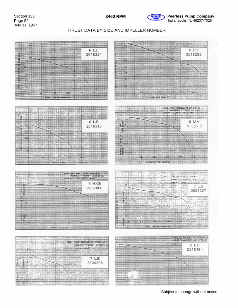
Section 133 Page 52 July 31, 1967
3460 RPM Peerless Pump Company Indianapolis IN, 46207-7026
THRUST DATA BY SIZE AND IMPELLER NUMBER
Subject to change without notice
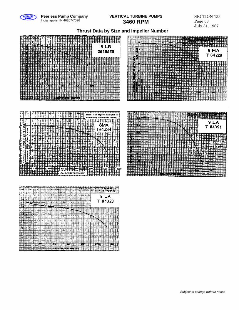
Peerless Pump Company Indianapolis, IN 46207-7026
VERTICAL TURBINE PUMPS 3460 RPM
SECTION 133 Page 53 July 31, 1967
Thrust Data by Size and Impeller Number
Subject to change without notice
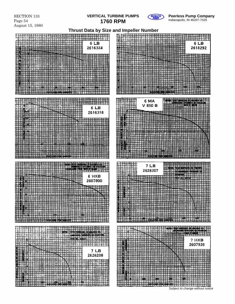
SECTION 133 Page 54 August 15, 1980
VERTICAL TURBINE PUMPS 1760 RPM
Peerless Pump Company Indianapolis, IN 46207-7026
Thrust Data by Size and Impeller Number
Subject to change without notice
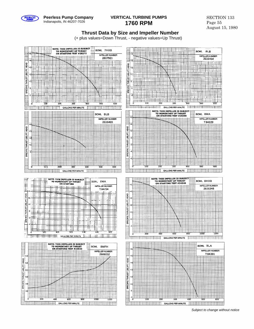
Peerless Pump Company Indianapolis, IN 46207-7026
VERTICAL TURBINE PUMPS 1760 RPM
SECTION 133 Page 55 August 15, 1980
Thrust Data by Size and Impeller Number (+ plus values=Down Thrust, - negative values=Up Thrust)
Subject to change without notice
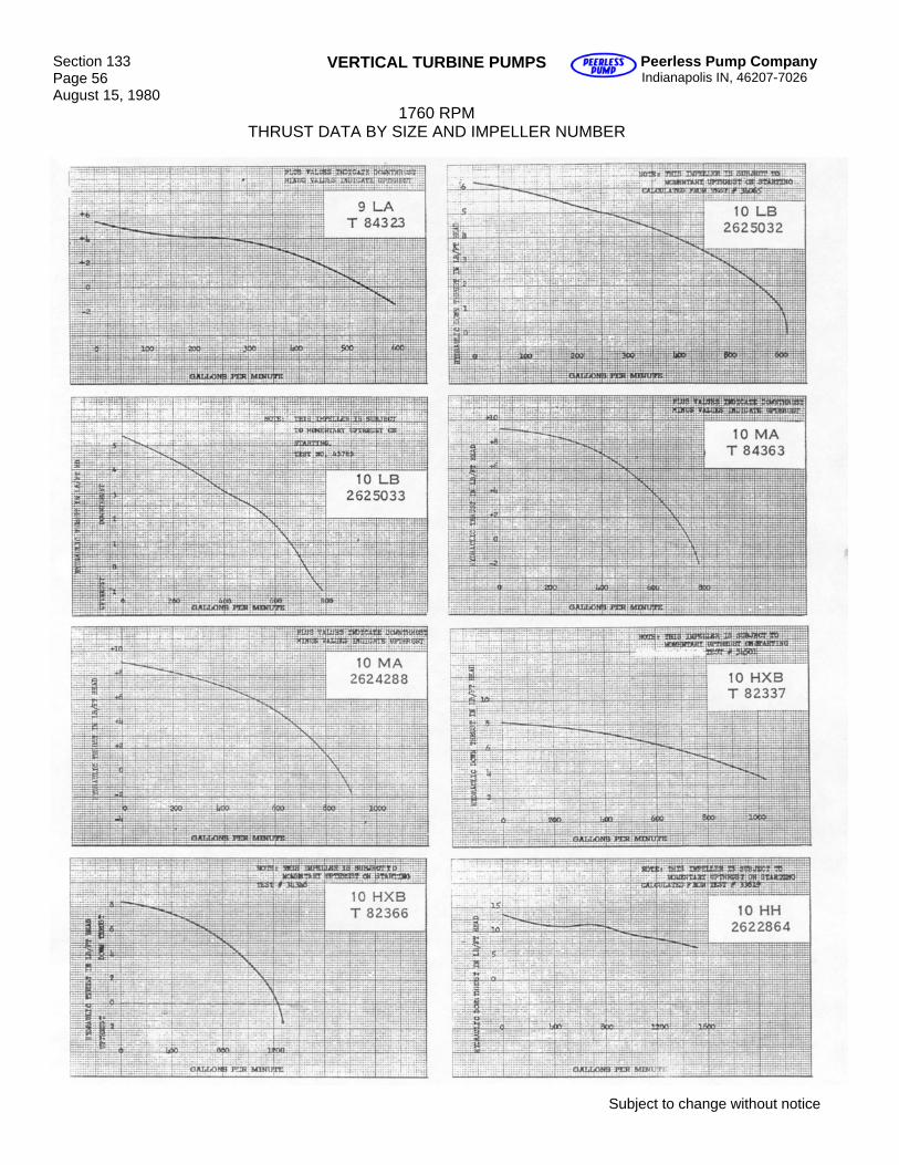
Section 133 Page 56 August 15, 1980
VERTICAL TURBINE PUMPS Peerless Pump Company Indianapolis IN, 46207-7026
1760 RPM THRUST DATA BY SIZE AND IMPELLER NUMBER
Subject to change without notice
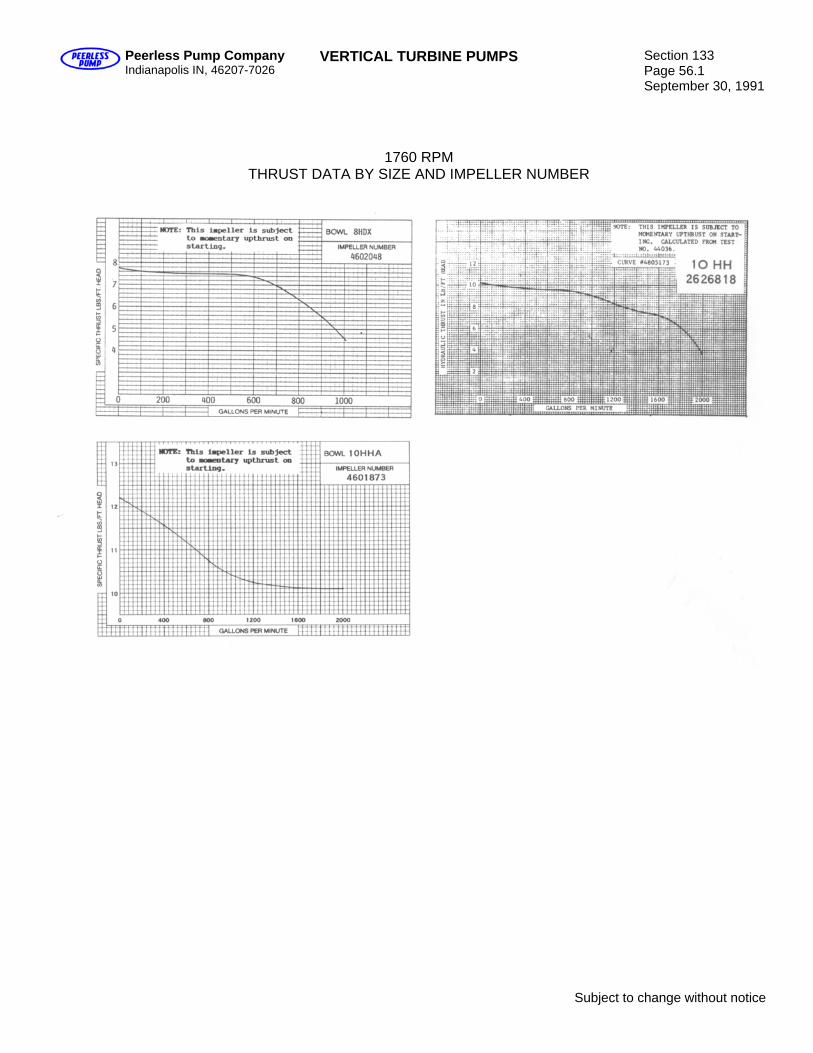
Peerless Pump Company Indianapolis IN, 46207-7026
VERTICAL TURBINE PUMPS Section 133 Page 56.1 September 30, 1991
1760 RPM THRUST DATA BY SIZE AND IMPELLER NUMBER
Subject to change without notice

Blank
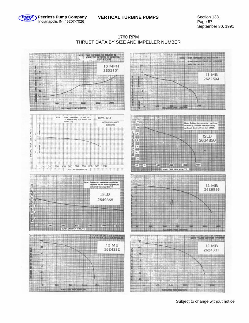
Peerless Pump Company Indianapolis IN, 46207-7026
VERTICAL TURBINE PUMPS Section 133 Page 57 September 30, 1991
1760 RPM
THRUST DATA BY SIZE AND IMPELLER NUMBER
Subject to change without notice
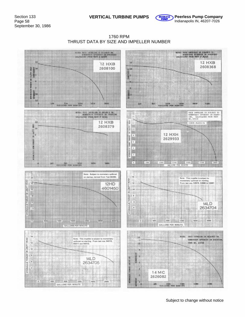
Section 133 Page 58 September 30, 1986
VERTICAL TURBINE PUMPS Peerless Pump Company Indianapolis IN, 46207-7026
1760 RPM
THRUST DATA BY SIZE AND IMPELLER NUMBER
Subject to change without notice
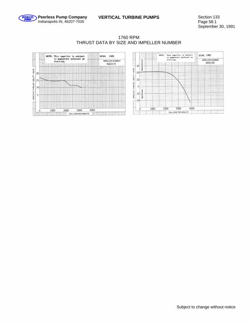
Peerless Pump Company Indianapolis IN, 46207-7026
VERTICAL TURBINE PUMPS Section 133 Page 58.1 September 30, 1991
1760 RPM
THRUST DATA BY SIZE AND IMPELLER NUMBER
Subject to change without notice

Blank

Peerless Pump Company Indianapolis IN, 46207-7026
VERTICAL TURBINE PUMPS Section 133 Page 59 August 15, 1980
1760 RPM
THRUST DATA BY SIZE AND IMPELLER NUMBER
Subject to change without notice
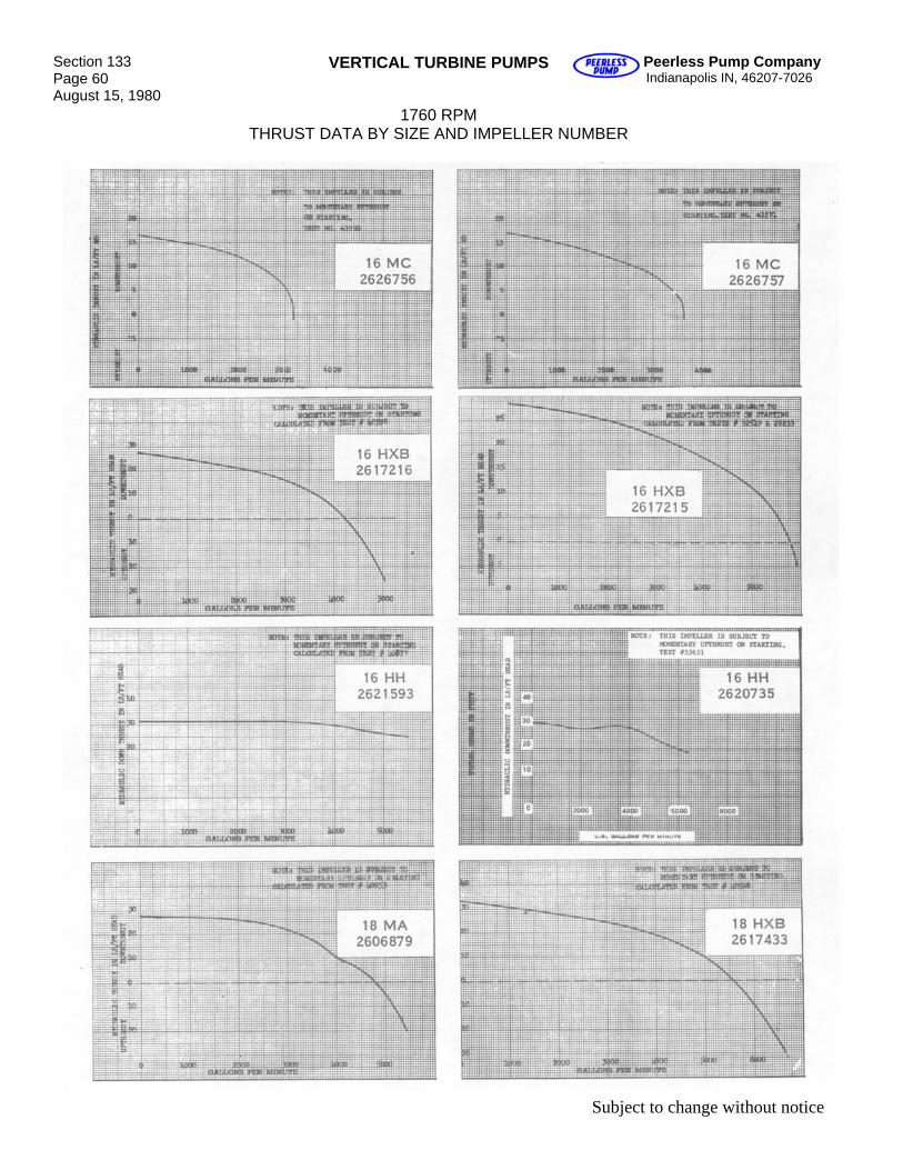
Section 133 Page 60 August 15, 1980
VERTICAL TURBINE PUMPS Peerless Pump Company Indianapolis IN, 46207-7026
1760 RPM THRUST DATA BY SIZE AND IMPELLER NUMBER
Subject to change without notice
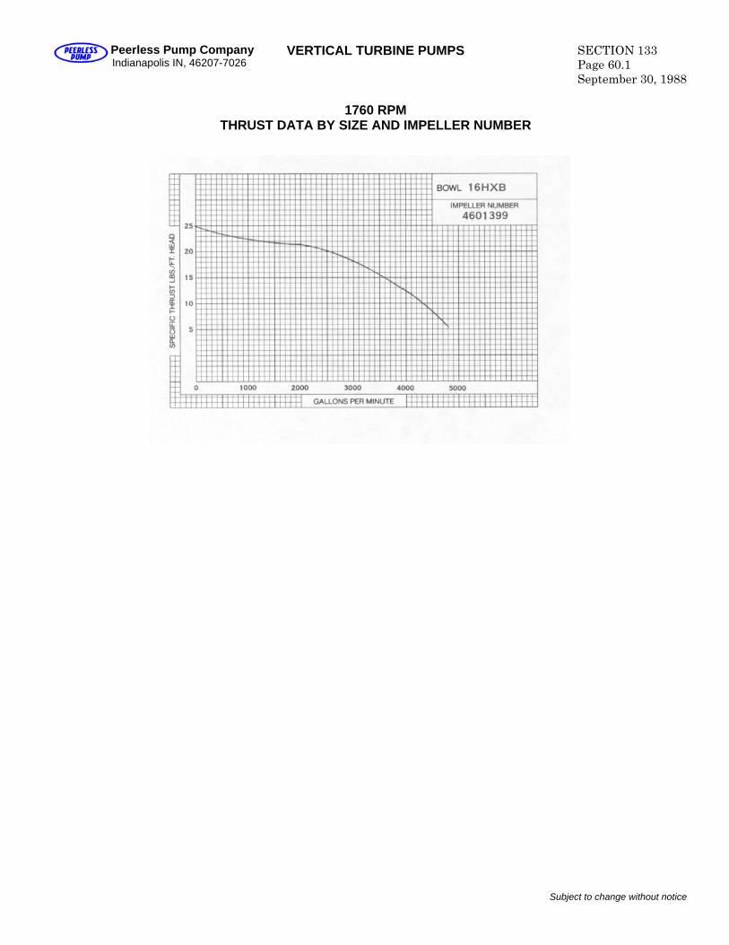
Peerless Pump Company Indianapolis IN, 46207-7026
VERTICAL TURBINE PUMPS SECTION 133 Page 60.1 September 30, 1988
1760 RPM
THRUST DATA BY SIZE AND IMPELLER NUMBER
Subject to change without notice

Blank
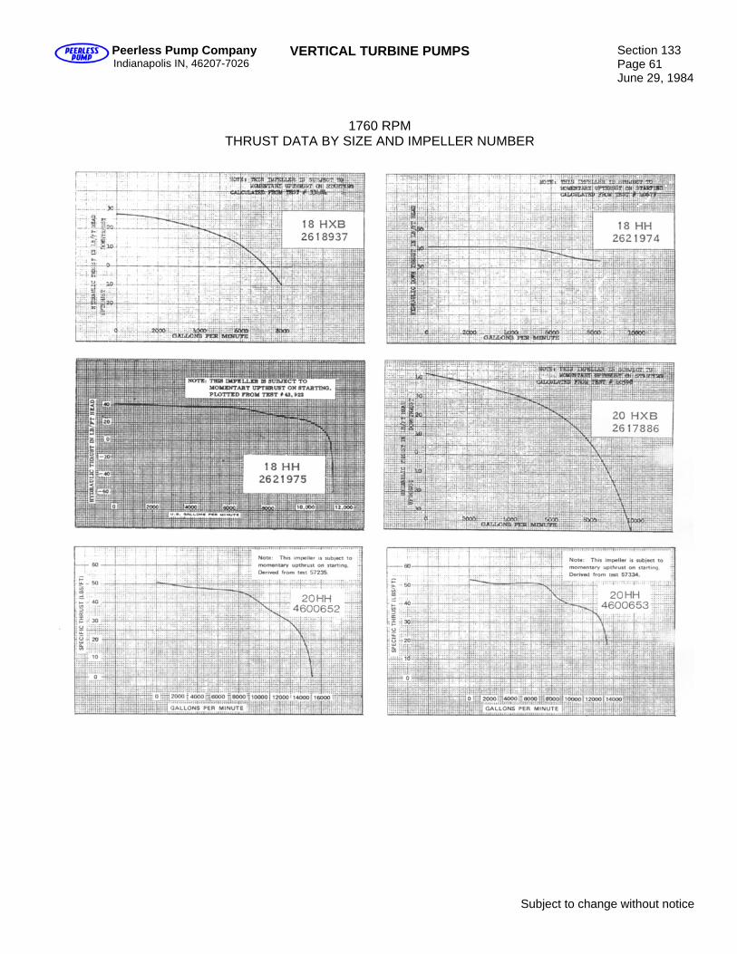
Peerless Pump Company Indianapolis IN, 46207-7026
VERTICAL TURBINE PUMPS Section 133 Page 61 June 29, 1984
1760 RPM THRUST DATA BY SIZE AND IMPELLER NUMBER
Subject to change without notice

Blank
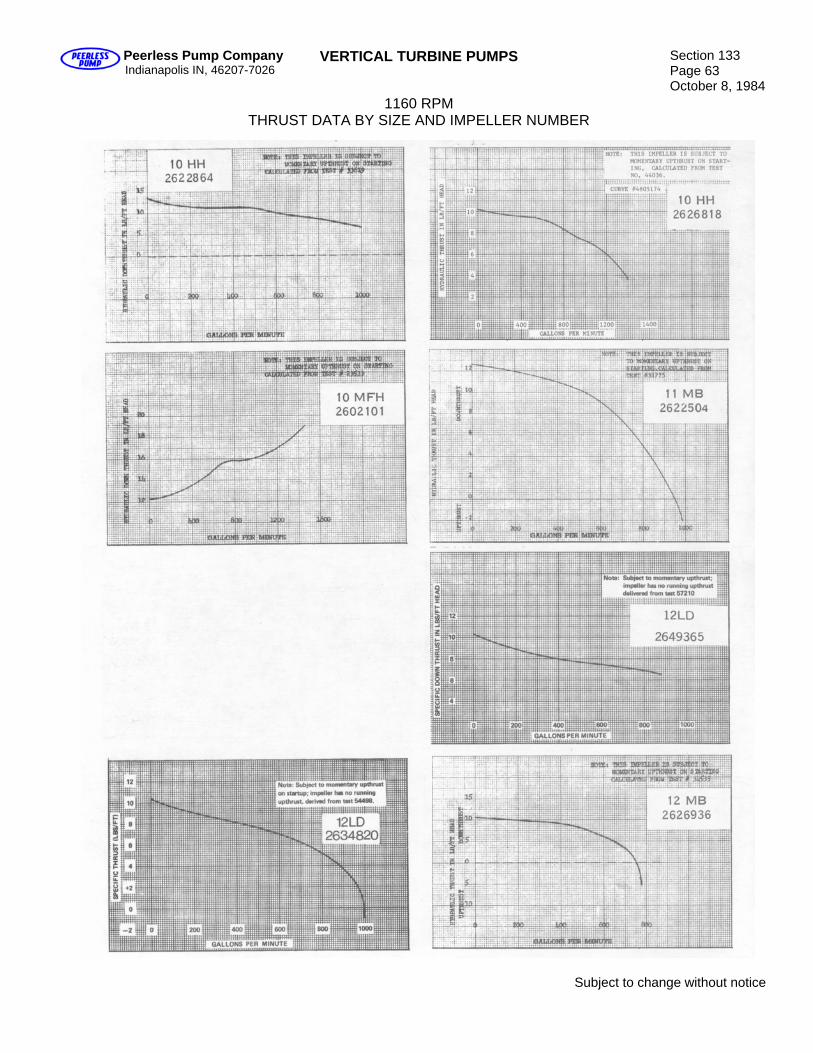
Peerless Pump Company Indianapolis IN, 46207-7026
VERTICAL TURBINE PUMPS Section 133 Page 63 October 8, 1984
1160 RPM THRUST DATA BY SIZE AND IMPELLER NUMBER
Subject to change without notice
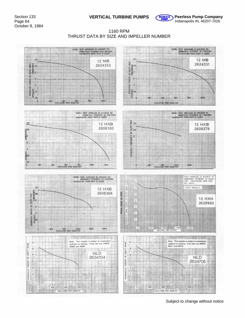
Section 133 Page 64 October 8, 1984
VERTICAL TURBINE PUMPS Peerless Pump Company Indianapolis IN, 46207-7026
1160 RPM THRUST DATA BY SIZE AND IMPELLER NUMBER
Subject to change without notice
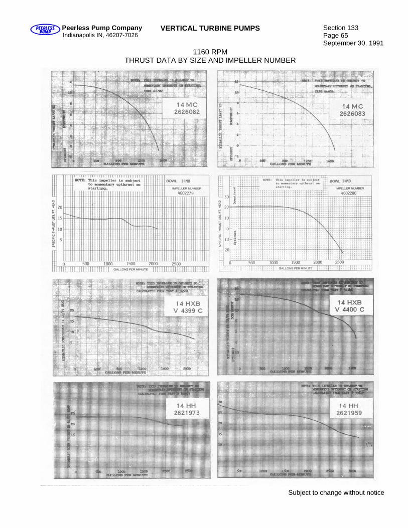
Peerless Pump Company Indianapolis IN, 46207-7026
VERTICAL TURBINE PUMPS Section 133 Page 65 September 30, 1991
1160 RPM THRUST DATA BY SIZE AND IMPELLER NUMBER
Subject to change without notice
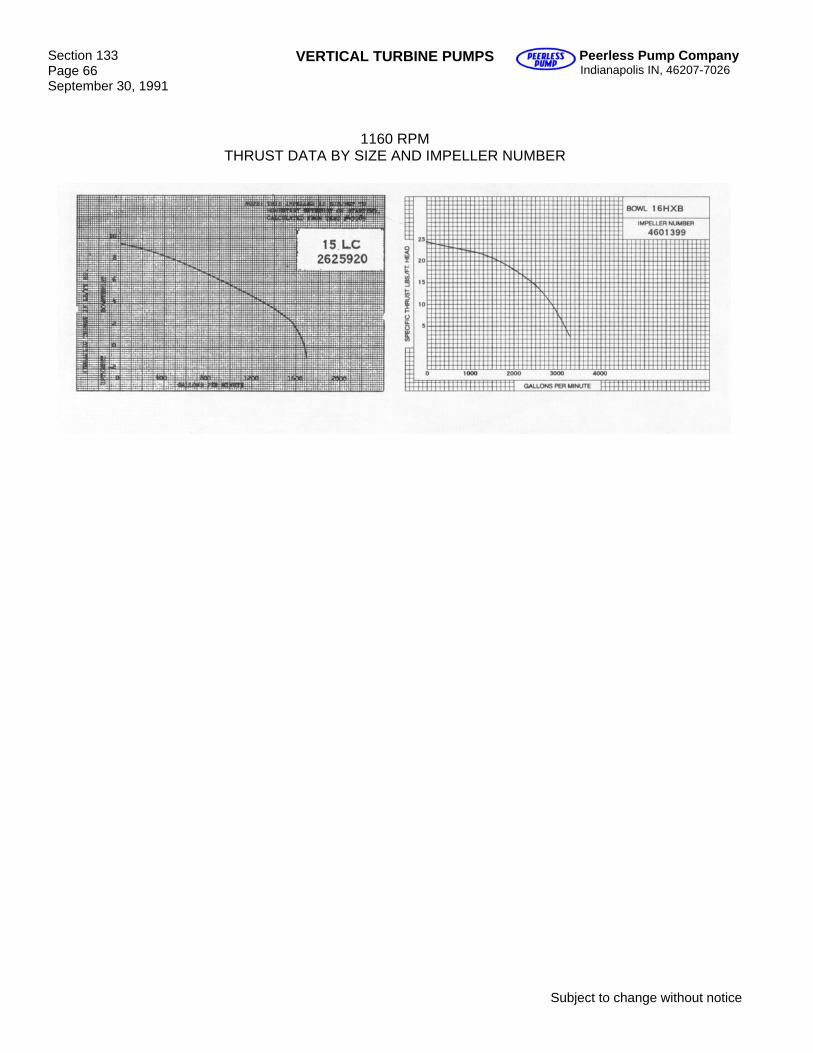
Section 133 Page 66 September 30, 1991
VERTICAL TURBINE PUMPS Peerless Pump Company Indianapolis IN, 46207-7026
1160 RPM THRUST DATA BY SIZE AND IMPELLER NUMBER
Subject to change without notice
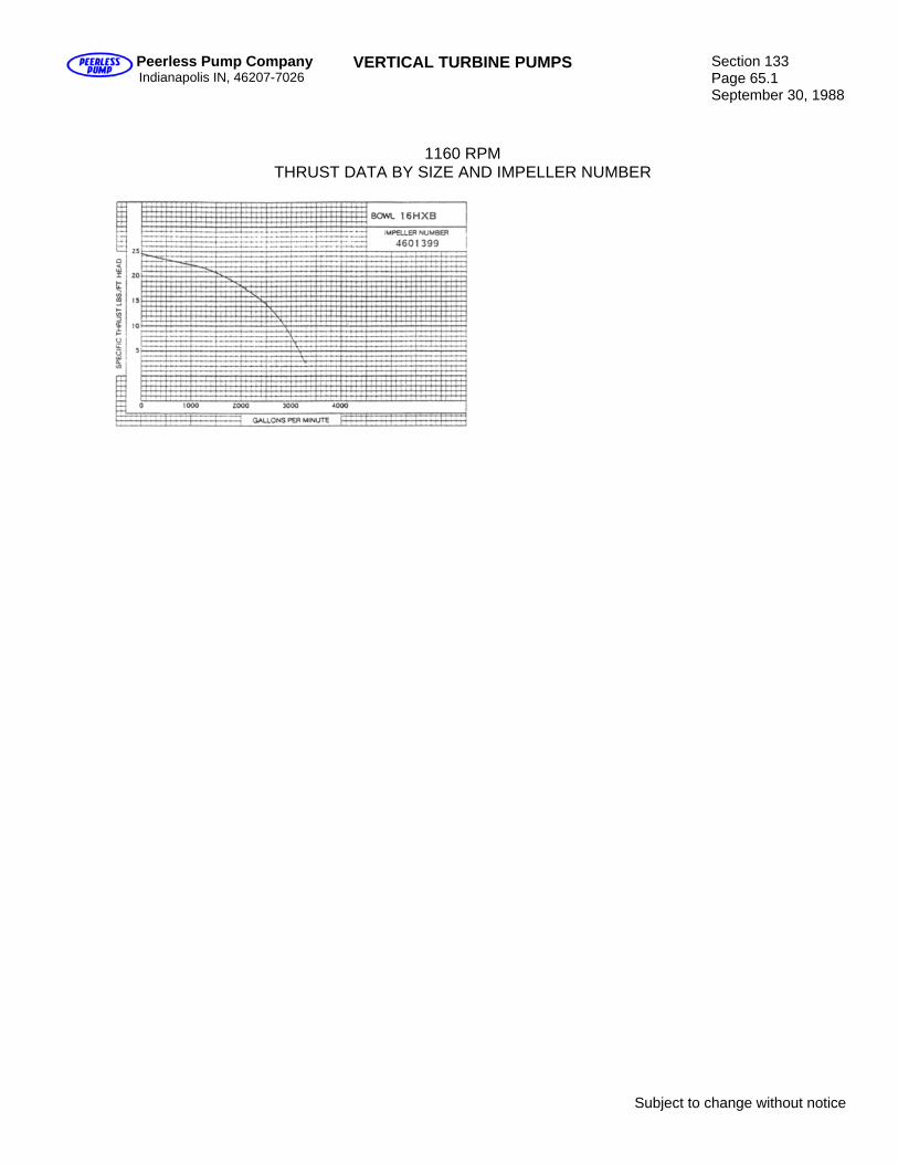
Peerless Pump Company Indianapolis IN, 46207-7026
VERTICAL TURBINE PUMPS Section 133 Page 65.1 September 30, 1988
1160 RPM THRUST DATA BY SIZE AND IMPELLER NUMBER
Subject to change without notice

Blank

Peerless Pump Company Indianapolis IN, 46207-7026
VERTICAL TURBINE PUMPS Section 133 Page 67 January 23, 1978
1160 RPM THRUST DATA BY SIZE AND IMPELLER NUMBER
Subject to change without notice
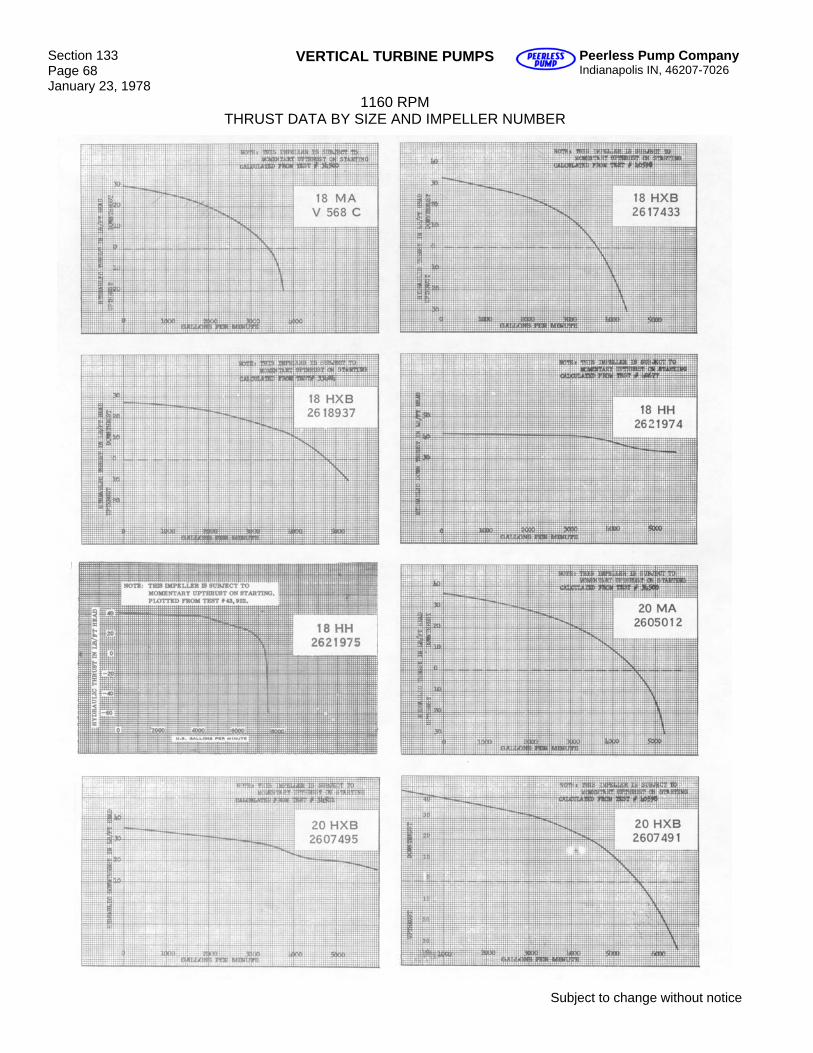
Section 133 Page 68 January 23, 1978
VERTICAL TURBINE PUMPS Peerless Pump Company Indianapolis IN, 46207-7026
1160 RPM THRUST DATA BY SIZE AND IMPELLER NUMBER
Subject to change without notice
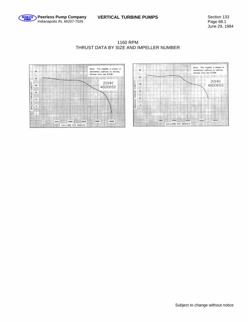
Peerless Pump Company Indianapolis IN, 46207-7026
VERTICAL TURBINE PUMPS Section 133 Page 68.1 June 29, 1984
1160 RPM THRUST DATA BY SIZE AND IMPELLER NUMBER
Subject to change without notice

Blank
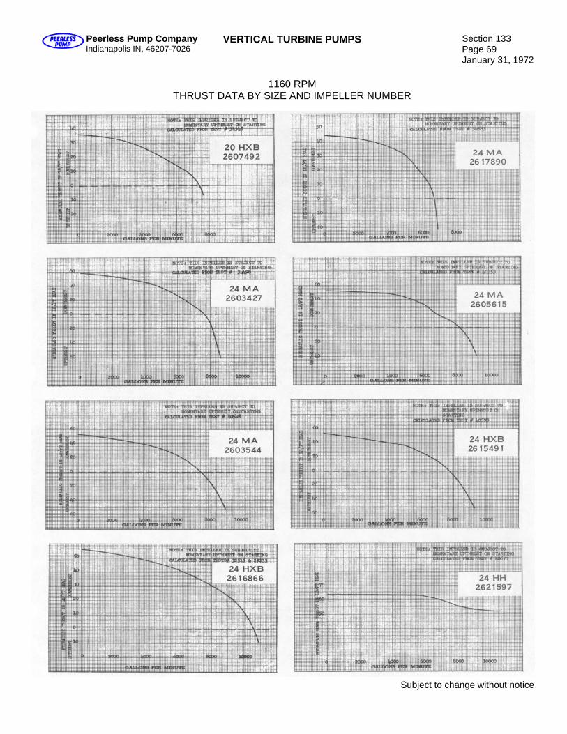
Peerless Pump Company Indianapolis IN, 46207-7026
VERTICAL TURBINE PUMPS Section 133 Page 69 January 31, 1972
1160 RPM
THRUST DATA BY SIZE AND IMPELLER NUMBER
Subject to change without notice
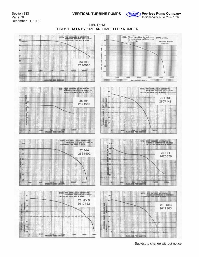
Section 133 Page 70 December 31, 1990
VERTICAL TURBINE PUMPS Peerless Pump Company Indianapolis IN, 46207-7026
1160 RPM THRUST DATA BY SIZE AND IMPELLER NUMBER
Subject to change without notice
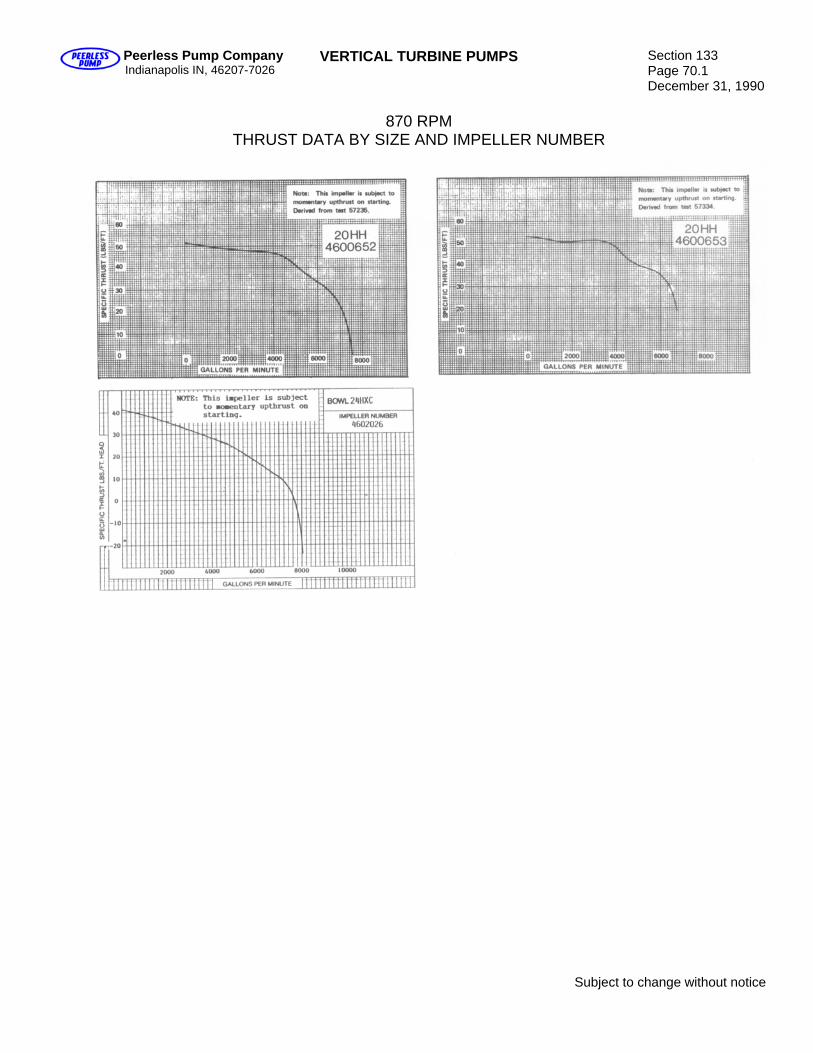
Peerless Pump Company Indianapolis IN, 46207-7026
VERTICAL TURBINE PUMPS Section 133 Page 70.1 December 31, 1990
870 RPM
THRUST DATA BY SIZE AND IMPELLER NUMBER
Subject to change without notice

Blank
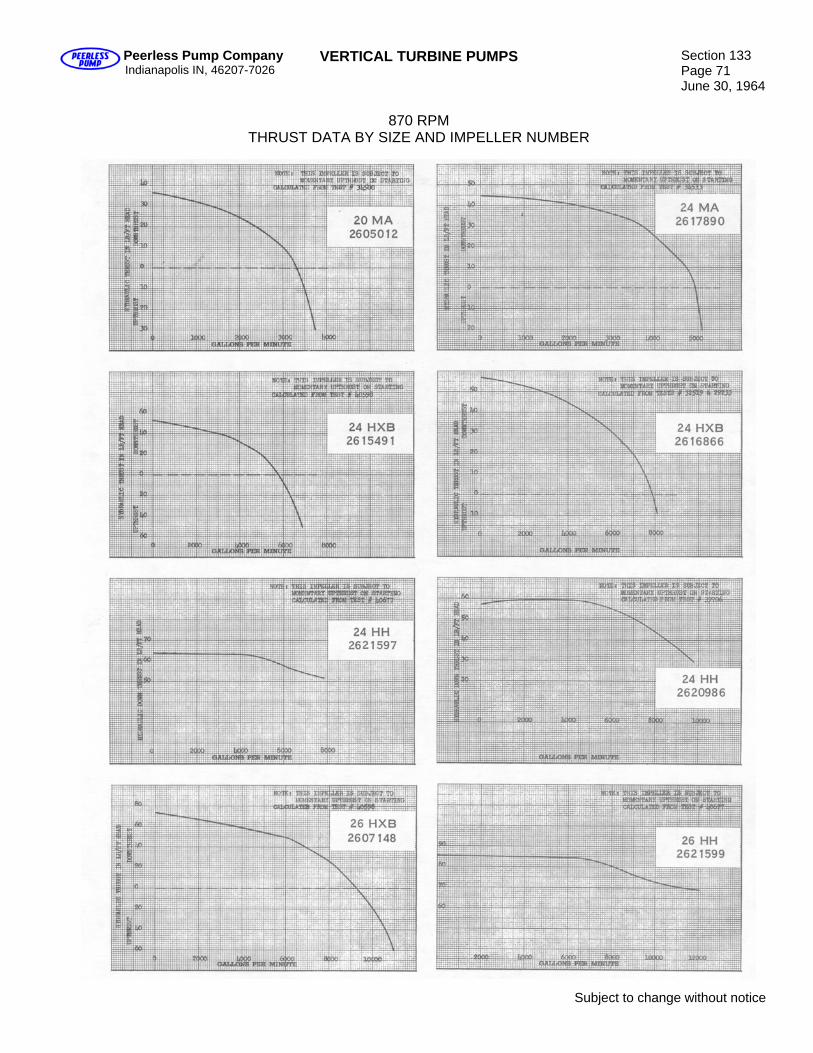
Peerless Pump Company Indianapolis IN, 46207-7026
VERTICAL TURBINE PUMPS Section 133 Page 71 June 30, 1964
870 RPM
THRUST DATA BY SIZE AND IMPELLER NUMBER
Subject to change without notice
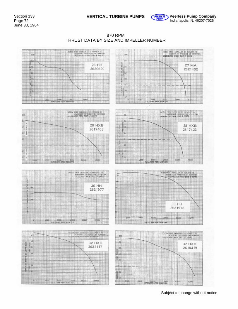
Section 133 Page 72 June 30, 1964
VERTICAL TURBINE PUMPS Peerless Pump Company Indianapolis IN, 46207-7026
870 RPM
THRUST DATA BY SIZE AND IMPELLER NUMBER
Subject to change without notice
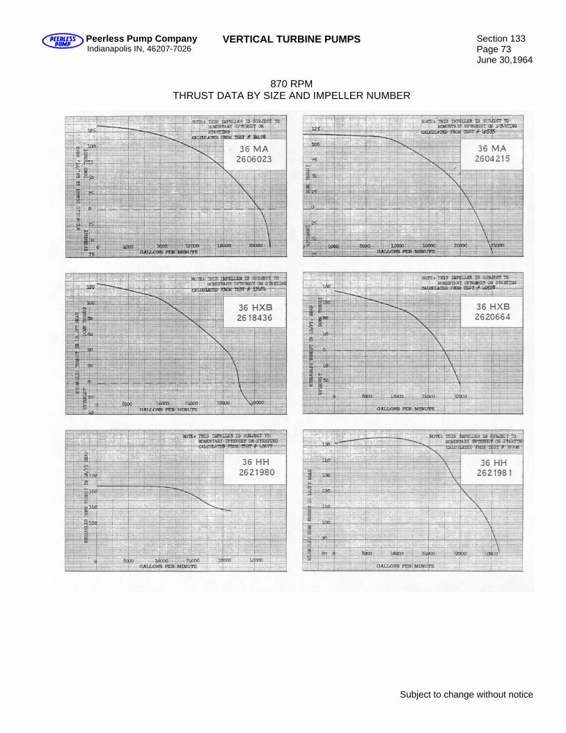
Peerless Pump Company Indianapolis IN, 46207-7026
VERTICAL TURBINE PUMPS Section 133 Page 73 June 30,1964
870 RPM
THRUST DATA BY SIZE AND IMPELLER NUMBER
Subject to change without notice
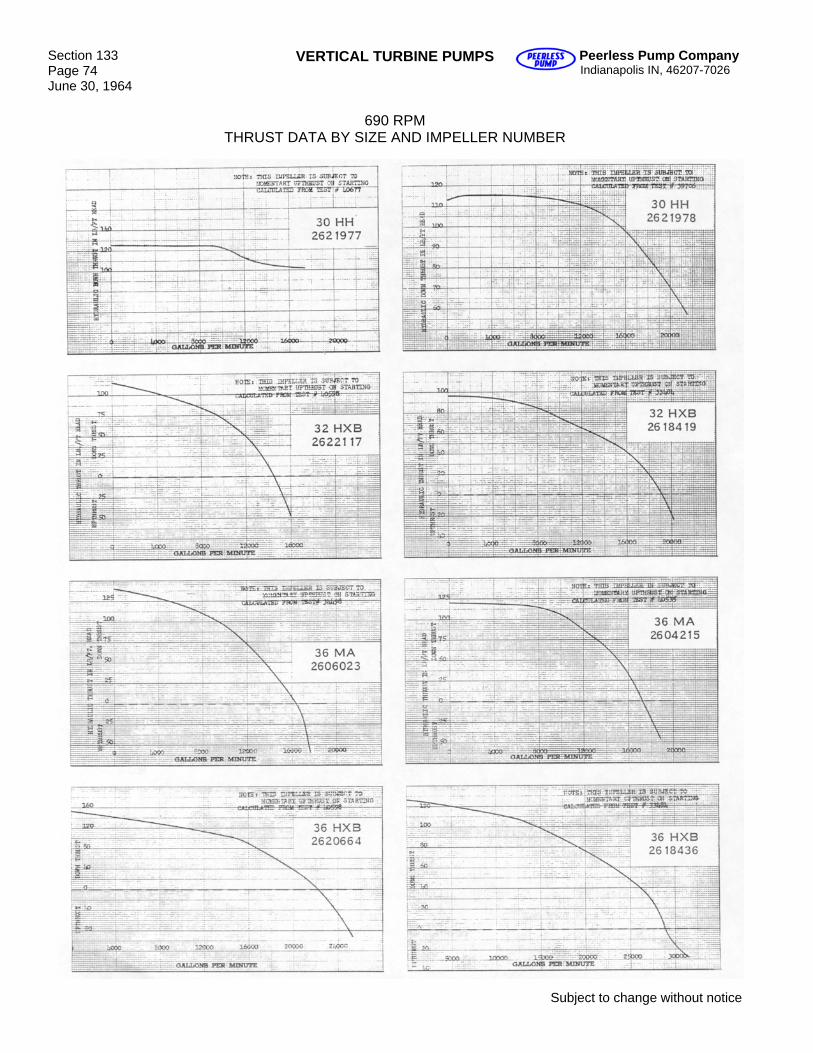
Section 133 Page 74 June 30, 1964
VERTICAL TURBINE PUMPS Peerless Pump Company Indianapolis IN, 46207-7026
690 RPM
THRUST DATA BY SIZE AND IMPELLER NUMBER
Subject to change without notice
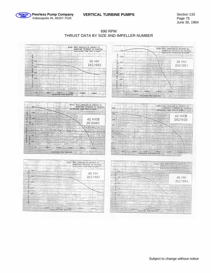
Peerless Pump Company Indianapolis IN, 46207-7026
VERTICAL TURBINE PUMPS Section 133 Page 75 June 30, 1964
690 RPM
THRUST DATA BY SIZE AND IMPELLER NUMBER
Subject to change without notice
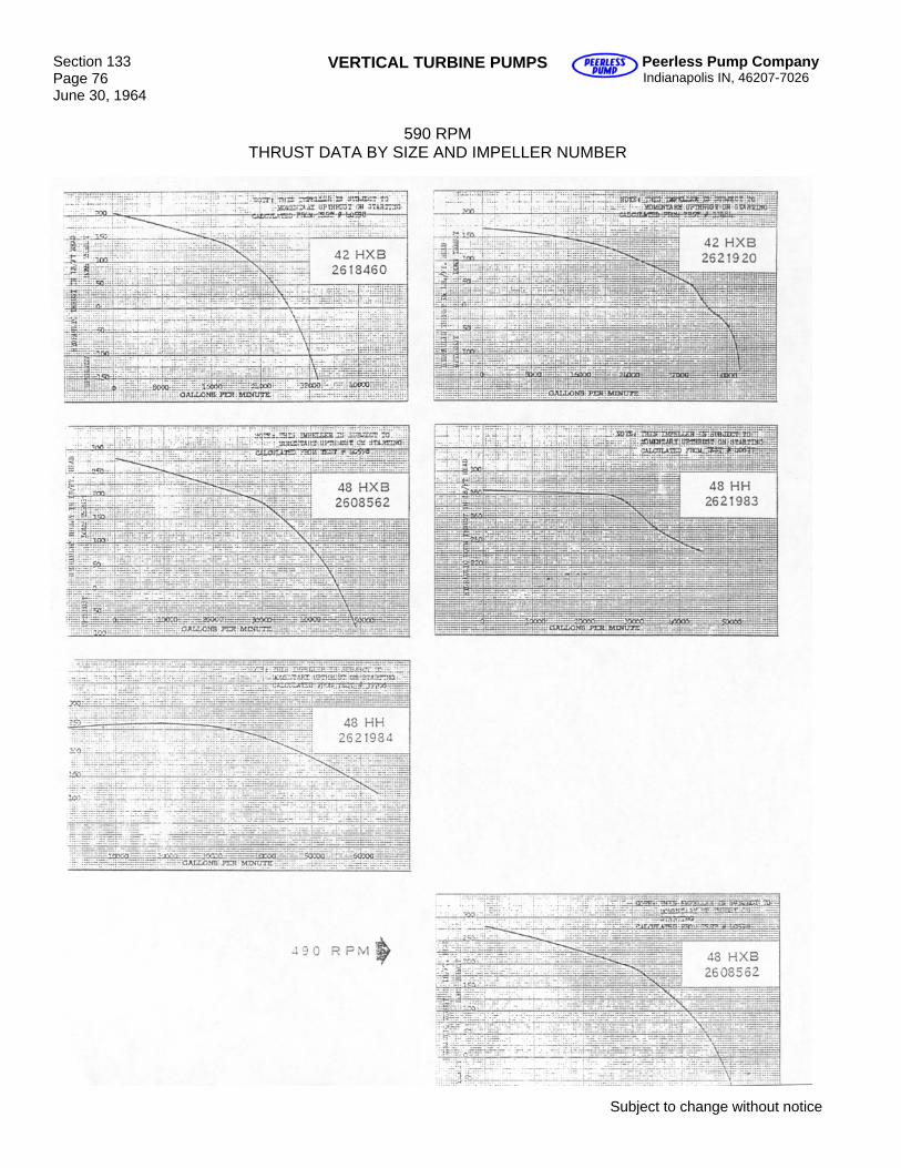
Section 133 Page 76 June 30, 1964
VERTICAL TURBINE PUMPS Peerless Pump Company Indianapolis IN, 46207-7026
590 RPM
THRUST DATA BY SIZE AND IMPELLER NUMBER
Subject to change without notice