Embed Size (px)
Citation preview

916
VERTICAL FLOW POND PIPING SYSTEM DESIGN CONSIDERTATIONS1
Timothy P. Danehy2, Tiff Hilton, George R. Watzlaf, Fred Johnson, Shaun L. Busler,
Clifford F. Denholm, Margaret H. Dunn
Abstract. Abandoned mine drainage is a major source of water pollution in
Pennsylvania, West Virginia, and other historical mining districts. Technology which
utilizes no harsh chemicals and no electricity, and requires minimal maintenance known as
passive treatment is being developed to address this pollution problem in a relatively
cost-effective manner. Specifically, acidic drainage with dissolved aluminum and/or
high iron content is now being successfully abated utilizing a916 type of passive system
which uses a component known as a Vertical Flow Pond (VFP). VFPs are also referred
to as Reducing and Alkaline Producing Systems or RAPS. Numerous papers and
technical investigations have provided documentation on the effectiveness of these
systems in treating discharges of various qualities and flow rates. Very little information,
however, is available regarding the piping systems used for the collection of the water
after passing through the treatment media. These piping systems are often referred to as
underdrains. Experience gained during installation and from on-going monitoring of
successful VFPs at the Jennings Environmental Education Center and Ohiopyle State Park
(PA Dept. of Conservation and Natural Resources) and within the Slippery Rock Creek
Watershed has led to the development of an innovative double-tiered, multiple-quadrant,
underdrain system. This type of underdrain has been recently installed at the De Sale
Restoration Area - Phase II (De Sale II) site in Venango Township, Butler County, PA.
This underdrain system is expected to aid in eliminating “dead areas” and in maintaining
the hydraulic conductivity of the treatment media by improving flow distribution and by
improving the ease and thoroughness of the flushing operation to remove accumulated
metal solids.
Additional Key Words: Passive Treatment, Constructed Wetlands, Acid Mine
Drainage, Flow Distribution, Flushing
1Paper presented at the 19
th Annual National Meeting of the American Society for Surface
Mining and Reclamation, Lexington, Kentucky, June 9-13, 2002. 2Timothy Danehy, EPI, BioMost, Inc., Cranberry Township., PA
Tiff Hilton, Mining Engineer, WOPEC, Lewisburg, WV
George R. Watzlaf, Environmental Engineer, US Department of Energy, NETL, Pittsburgh,
PA
Fred Johnson, Reclamation Manager, Amerikohl Mining, Inc., Butler, PA
Shaun L. Busler, Biologist, BioMost, Inc., Cranberry Twp., PA
Clifford F. Denholm, Environmental Scientist, BioMost, Inc., Cranberry Twp., PA
Margaret H. Dunn, PG, Stream Restoration Inc.(PA Non-Profit), Cranberry Twp., PA
Proceedings America Society of Mining and Reclamation, 2002 pp 916-936
DOI: 10.21000/JASMR02010916

917
Introduction
Vertical Flow Ponds are flexible in design and can passively treat acidic discharges which
contain dissolved aluminum, dissolved oxygen, ferric iron, or any combination thereof. In order
to maintain hydraulic conductivity in the treatment media, however, accumulated metal solids
require removal on a periodic basis. Recent tests documenting dye migration in various passive
treatment system components also indicate that short-circuiting is a consideration (Peart and
Cooper, 2000). The presentation of this paper is an effort to share information regarding
promising developments including design considerations, installation and preliminary
performance of vertical flow-type and other passive treatment system components in order to
contribute to the on-going improvement of passive treatment technology. A recently installed
system is included as an example.
De Sale Restoration Area - Phase II: System Overview
Location
The De Sale Restoration Area - Phase II (De Sale II) site is located in Venango Township,
Butler County, PA within the headwaters of Seaton Creek, the major tributary, most heavily
impacted by abandoned mine drainage, in the Slippery Rock Creek Watershed (Gwin Engineers,
1970). See Figure 1.
PENNSYLVANIA

918
Figure 1. Location map.
Water Quality
Table 1. Representative pre-construction raw water data.
Statistical
Summary
Flow
(gpm)
Lab. pH
Acidity
(mg/l)
T. Fe
(mg/l)
T. Mn
(mg/l)
T. Al
(mg/l)
mean
134
3.5
179
9
36
7
range
22 - 338
3.0 - 4.3
32 - 420
2 - 20
10 - 81
2 - 14
75
th percentile
204
3.7
233
10
50
8
Notes: n[flow] = 12 (Gwin Engineers, 1970); n[ water quality parameters] = 23 (PA DEP,
1998); pH not averaged from H ion concentration; Observations and measurements of flow
during pre-construction and monitoring for the CMRS report indicated that the Scarlift flow
data was applicable. Comparison of individual flow measurements with corresponding water
quality parameter readings indicates dilution at higher flows.
System Design
Overview
The discharge is conveyed through the following components in series: Stream Intake
Forebay Vertical Flow Pond (2 in parallel) Settling/Flush Pond Wetland Horizontal
Flow Limestone Bed. See Figure 2.
Stream Intake
Due to extensive mining in the headwaters and the diffuse nature of the seep zone, the major
contributor of flow to the unnamed tributary was abandoned mine drainage. This channelized
flow provided the necessary collection of the drainage for the passive system. In order to
prevent overwhelming the system during high-flow and precipitation events, a controlled-flow,
stream intake was installed. The intake was designed to allow the 200-gpm design flow to enter
the system, any excess flow crests a 16 ft wide concrete weir and remains in the stream channel.

919
The design flow was based on the 75th
percentile flow, determined from Operation Scarlift
monitoring data. The flow to the system is restricted by the pipe diameter and length with the
maximum available head controlled

920
by the weir.
Forebay
The site provided a limited amount of drop (difference in elevation) within the preferred
construction area. In order to obtain the needed drop, the stream intake was installed
approximately 400 ft from the VFP. This required the drainage to be conveyed with very little
elevation change. A long forebay was installed to inhibit settleable solids and some iron solids
from entering the VFPs (Watzlaf et al., 2000). The pond-like configuration of this component
allows for a small difference between inlet and outlet elevations and minimizes the maintenance
issues associated with conveying abandoned mine drainage utilizing nearly flat pipes or open
channels. The forebay was constructed with a 5 ft bottom width, 29 ft top width, 2:1 inside
slopes, about 4.5 ft design water depth, and about 6 ft total depth. The outlet of this component
is a single 10 inch pipe that terminates in a 10 inch x 8 inch x 8 inch tee. From each side of the
tee the 8 inch pipe extensions discharge into respective VFP. Flow rate is controlled by rotating
a 90 elbow attached to the 8 inch pipe with a rubber coupler.
Vertical Flow Ponds
The primary purposes of this component are acid neutralization and alkalinity generation (PA
DEP, 1999). A parallel configuration was utilized allowing for continual treatment of water
during future maintenance of this component. To address hydraulic conductivity, flow
distribution and flushing,an innovative, two-tiered, quadrant-type underdrain system was
installed. Both ponds were lined with geotextile fabric to provide ground stabilization for
placement of a 0.5 ft layer of AASHTO #57 (1.5 inch) “bedding stone” and to minimize loss of
treatment media. The “bedding stone” was overlain by the lower tier of the underdrain. Two
feet of AASHTO #1 (4 inch) limestone (90% calcium carbonate) aggregate was spread over the
first layer of pipes. A second (upper tier) underdrain similar to the first was installed and
covered by a second, two-foot thick, layer of limestone. Spent mushroom compost (0.5 ft
thickness) was then spread over the limestone. Individual flush valves and outlet controls were
installed for each “cell” of the underdrain. Approximately two feet of water caps

921
Figure 2. Flow diagram of De Sale II Passive Treatment System.
the treatment media. (For a more detailed description of the underdrain, see VFP Underdrain

922
Design Considerations.)
Settling/Flush Pond (SP)
VFPs are typically followed by a settling pond to allow for the oxidation and/or settling of
metal precipitates. This convention was applied to the De Sale II site with modifications. A
valved, draw-down device (10 inch diameter) was added to the design. This allows the water
level to be lowered about 2 ft prior to a flushing event. About one week prior to flush the water
level in the settling pond is to be lowered by opening the valve on the draw-down device. Just
before the flush is to occur, the valve is to be shut. Sufficient capacity was designed into the
volume of the settling pond to allow the entire flush volume to be retained to allow for settling
and accumulation of solids.
Wetland (WL)
The WL component is included to allow additional oxidation and/or settling of solids
(Waztlaf et al., 2000). To encourage natural function and maximize effective retention,
microtopographic relief, directional earthern baffles, and vegetation with high species diversity
and density were included in the wetland design.
Horizontal Flow Limestone Bed (HFLB)
To encourage oxidation and removal of manganese (Hellier, 1999) as well as additional
alkalinity generation, a HFLB was included as the final treatment component in the system. The
design is straightforward with the discharge being directed into the HFLB (containing five feet of
limestone aggregate) from the WL via a rock-lined spillway. The drainage is encouraged to
flow horizontally through the limestone to a perforated header along the outlet end near the base
of the component. A riser pipe extends to within one foot of the top of the limestone, the design
water level.
923
VFP Underdrain Design Considerations
Background of Underdrain Development
Underdrains have been installed in a variety of configurations. Reportedly, the standard
design utilizes a single, solid header installed on the short side of the VFP with perforated
laterals extending parallel to the longitudinal axis of the pond. The laterals are generally
standard perforated pipe installed on 6 ft to 10 ft centers. A VFP utilizing this configuration
was installed at the Harbison Walker Restoration Effort - Phase I (Harbison Walker I) site in
Ohiopyle State Park (PADCNR), Stewart Twp., Fayette Co., PA (Stream Restoration, 2000).
Other systems have utilized multiple header configurations such as the system installed at
Jennings Environmental Education Center (PADCNR), Brady Twp., Butler Co., PA. The
laterals at Jennings are connected to three separate headers which are combined into a common
outlet device. Both systems have successfully treated water to the anticipated water quality, or
better, since installation.
The outlet device at the Jennings site incorporates a flexible design which allows the outlet
water level to be readily adjusted. At the time of installation, the Jennings VFP was anticipated
to retain aluminum with the majority of iron passing through the system; however, continued
monitoring indicates higher than expected levels of iron retention (Watzlaf et al., 2000;
Jennings, 1999). In order to maintain sufficient hydraulic conductivity, the Jennings VFP has
been periodically flushed by lowering the outlet control device.
In order to facilitate periodic flushing, the outlet device at the Harbison Walker I site
included a solid, straight, flush pipe extending from the header pipe near the bottom of the VFP
to a settling pond. As noted at the Jennings site, the Harbison Waker I VFP has retained
significant quantities of iron (Stream Restoration, 2000). The original design utilized a
threaded plug at the outlet of the flush pipe.
Both the Jennings and Harbison Walker I systems have a single-tier, underdrain system
installed near the treatment media base.
924
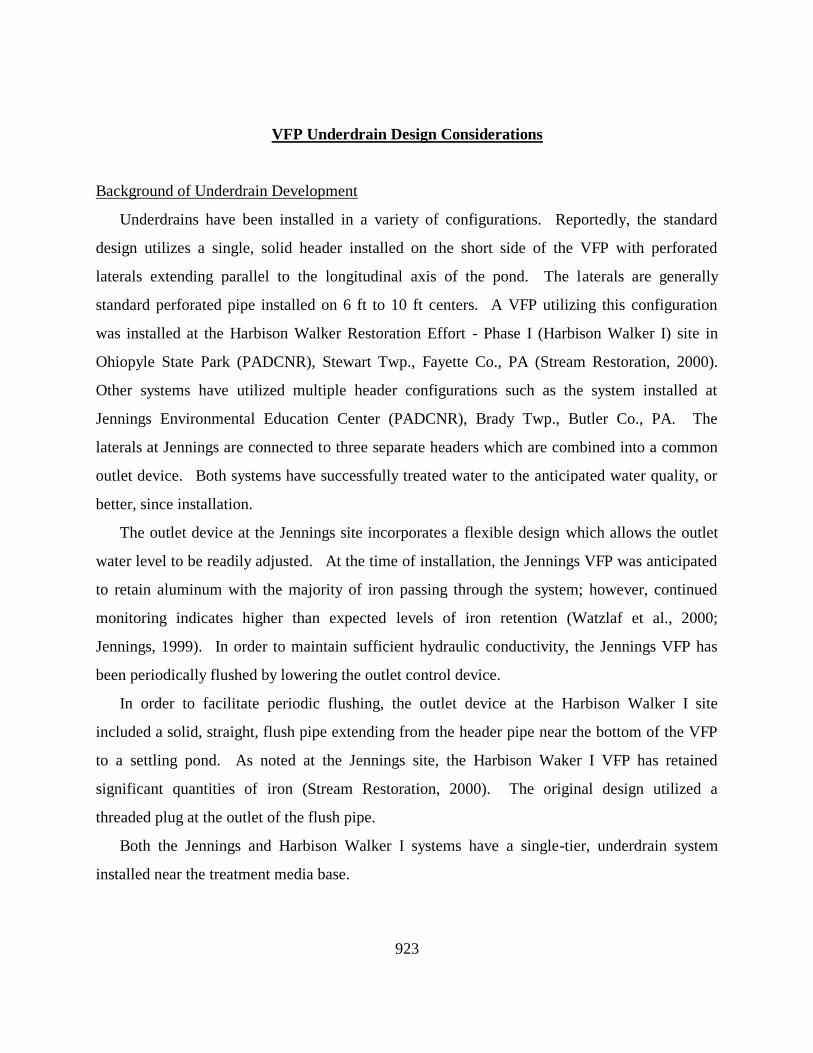
De Sale II Underdrain Overview
A more extensive underdrain system was developed for the De Sale II VFP in an attempt to
optimize flow distribution and flushing of accumulated iron and aluminum solids. The
underdrain was constructed of 4 inch Schedule 40 PVC pipe. Perforated laterals were placed on
4.5 ft centers and connected to a solid header with a sanitary-type tee. Perforations were
hand-drilled with two, 0.5 inch perforations approximately 30 from the top of pipe. The
perforation spacing was equal to the lateral spacing (4.5 ft). Four separate header pipes were
used for each underdrain thus dividing the surface area into approximately equal quadrants.
Two underdrains are installed in each vertical flow pond, one at the base of the AASHTO #1
layer and one in the middle of the four-foot thick layer of limestone aggregate. This effectively
divides each VFP into eight separate “cells”, four upper and four lower. Two VFPs are installed
in parallel producing a total of sixteen separate cells with individual discharge locations and
flush valves. See Figures 3 & 5.
Figure 3. Typical installation of quadrant-type underdrain system.

925
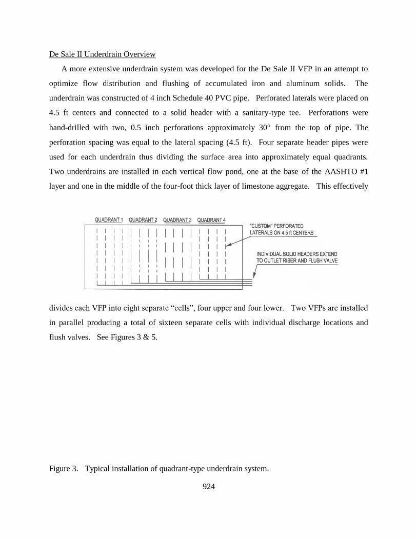
Each header pipe extends from the treatment media through the breastwork to an individual
4 inch slide-type gate valve. Prior to the gate valve, a tee was installed about mid-way through
the breastwork to create a riser which leads to the primary outlet for that cell. Each outlet
included a 4 inch by 3 inch rubber reducer into which a 3 inch riser (1.5 ft section with 3 inch
90 elbow) was inserted. The reducer was equipped with two stainless steel hose clamps. The
4 inch hose clamp fastens the reducer to the 4 inch riser pipe. The 3 inch clamp was used to
vertically adjust the 3 inch riser. See Figure 4.
926
Figure 4. Typical outlet riser detail.
Flow Distribution
During normal operation of the Vertical Flow Ponds all sixteen cells discharge. This is
intended to reduce short circuiting and maximize effective retention time. Short circuiting has
been documented as a potential issue in the efficacy and long-term operation of vertical
flow-type passive systems. This was investigated by participants in the Jennings Water Quality
Improvement Coalition through the construction of an overdrain system and subsequent dye
testing at Jennings and other sites. The dye testing indicated that the flow was not evenly
spread throughout the system. Two
separate dye tests at Jennings documented that the flow had a maximum disbursement covering
less than 20% of the total treatment media surface with the momentum of the influent potentially
responsible for the observed amount of distribution (Peart and Cooper, 2000).
To overcome this situation, the underdrain installed at the De Sale II site includes individual
outlet controls for each cell. The individual outlets allow flow rates to be controlled in each
cell within the VFP. With all sixteen outlets discharging approximately equal flow volumes,
distribution throughout the system can be assumed; however, this does not take into account
distribution variability within individual cells.

927
Perforation Size and Spacing
Standard perforated pipe has two, 0.625 (5/8) inch perforations every 5.25 inches. This is a
good design for customary applications (i.e. foundation drains); however, this type of perforation
configuration may not be particularly well suited for the distribution of acid mine drainage
within the treatment media of a VFP. According to standard orifice flow calculations, relatively
few linear feet of standard perforations are required to reach the maximum flow volume capacity
of a 4 inch pipe. Based on accepted formulae for Orifice and Pipe Flows, at a minimal given
head (<0.1 feet), standard 4 inch PVC perforated pipe reaches maximum carrying capacity
within approximately 10 linear feet.
Through the utilization of smaller orifices which are less frequently spaced, the length of
perforated 4 inch pipe required to reach maximum carrying capacity is extended. At a minimal
given head (<0.1 ft), two 0.5 inch perforations every 4.5 ft requires about 150 linear feet to reach
the maximum carrying capacity of a 4 inch pipe. This potentially could increase the effective
retention time within the treatment media.
To summarize, a quadrant underdrain with less frequently spaced perforations is expected to
decrease short circuiting thus increasing the effective retention time within the treatment media.
System Flushing
Vertical Flow Ponds typically retain significant amounts of iron and aluminum (Watzlaf et
al., 2000; Stream Restoration, 2000; Jennings, 1999). The accumulation of solids in the
treatment media has a potential adverse effect on hydraulic conductivity. A simple method of
removing these accumulated solids is head-driven flushing. Individual flush valves were
installed for each cell at De Sale II. These valves are located at approximately the same
elevation as the bottom of the VFP. See Figure 5.
With a separate valve for each cell, a specific portion of the VFP can be flushed. Here
again, the total volume of water which can pass through a 4 inch pipe at a given head is the
limiting factor, not the number of orifices. During flushing, removal of the maximum amount
of accumulated precipitate throughout the entire treatment media is desired. Through smaller

928
orifices and less frequent perforation spacing, the length of perforated pipe needed to achieve the
maximum carrying
Figure 5. Typical cross section of vertical flow pond.
capacity of a single 4 inch pipe is increased. At the De Sale II site, this increase is about 15
fold.
By decreasing the total amount of treatment media volume being flushed per valve, flushing
efficacy should be increased. Reducing the volume of treatment media being flushed was
achieved in two ways: 1) dividing the surface area of the treatment media into quadrants and 2)
installing two tiers of piping within the treatment media. This reduces the total number of
orifices feeding a single 4 inch pipe and subsequently increases the velocity of water traveling
through each orifice. This higher velocity would tend to dislodge more metal solids in the

929
media during a flushing event.
By increasing the number of laterals within a VFP, the average distance from within the
treatment media to a perforation is decreased. In a typical VFP with three feet of treatment
media underlain by laterals installed on 10 foot centers having two perforations every 5.25
inches, the maximum distance from a perforation is about 6 feet. The De Sale II design has a
maximum distance of about 3.5 feet from any point within the treatment media to a perforation.
Based on preliminary test flushing of other VFPs with similar underdrain systems, a flushing
event takes 15 to 20 minutes per cell. This is based on the amount of time required for the
discharge to “run clear” once the valve is opened. Also, in order to increase the amount of
solids removed from the underdrain system during flushing, the valve may be opened and shut
several times to “agitate” the system. Due to “water hammer”, brief, yet notable discharge has
been observed at the primary discharge outlet for the cell being flushed when the valve is shut
rapidly. Visual observation indicates that a significant amount of solids are expelled through
the primary outlet as well as the flush pipe during this procedure. This phenomena is expected
to be beneficial in long-term system performance.
Work is currently being coordinated with the US Department of Energy, National Energy
Technology Laboratory in Pittsburgh, PA to quantify metals retention during operation and
amount of release during flushing events.
Preliminary System Performance of Each Component
Intake & Forebay
On January 31, 2001, a flow of 187 gpm was measured using a calibrated 14-gallon bucket.
Due to the relatively short time needed to fill the container, this flow is subject to notable
sampling error. Flows were measured on the same date at each individual VFP inlet, the sum
was 203 gpm. The depth of flow over the 16' wide dam was also measured with a calculated
flow of 267 gpm. This indicates the 200-gpm design flow can be achieved without
overwhelming the system while excess flow remains within the stream channel. Within the

930
forebay, slight decreases in metal concentrations have been observed.
Vertical Flow Pond
The preliminary performance of the De Sale II site follows patterns observed at other
Vertical Flow Ponds (VFPs). Both influent and effluent water quality data at the two parallel
VFPs are extremely similar. For the first month of operation, sulfate, sodium and potassium
concentrations were greater in the effluent than in the influent. Only in the last month or two
are sulfate concentrations lowered as the water passes through the systems. However, a
consistent odor of hydrogen sulfide indicates that sulfate reduction has been occurring since the
beginning of operation. Dissolved oxygen concentrations have been at saturation levels in the
influent (9-13 mg/L) and near zero in the effluent (<0.2 mg/L). Manganese was removed in an
initial two-month period. The removal ceased, presumably due to a filling of the available
adsorption sites.
Changes in other parameters have been more consistent. Influent pH values averaged 3.2
compared to 7.0 in the effluent. Total alkalinity measured in the field has been at 50 to 100
mg/L (as CaCO3) in the effluent over the last four months (no alkalinity was in the influent).
Influent net acidity has averaged 250 mg/L (as CaCO3). The effluent water has always been net
alkaline and has averaged 120 mg/L (as CaCO3). Most of this generated alkalinity has been
used to neutralize acidity due to hydrogen ions (low pH) and acidity generated upon hydrolysis
of metals. Iron and aluminum concentrations are decreased from 34 to 4 mg/L and from 12 to
<0.5 mg/L, respectively. Other trace metals, cobalt, nickel and zinc have been lowered from 0.7
to <0.02 mg/L.
Rates of acidity removal on an area basis have ranged from 6 to 44 g/day/meter squared and
have averaged 27 g/day/meter squared. These values are consistent with several other VFPs
(Watzlaf et al., 2000). Regardless of flow, iron and aluminum are removed to low levels and
pH is increased to about 7.0. Therefore, these acidity removal rates are dependent on flow and
are greater at higher flows.
Settling Pond & Wetland

931
The settling pond component was installed primarily for use during flushing events. The
combined surface area of both components are considered during evaluation. Monitoring is
conducted of the wetland effluent. The settling pond and wetland were constructed within a
groundwater discharge zone and preliminary monitoring and visual observation indicate the
interception of degraded, shallow subsurface drainage. The quality and quantity of this drainage
impacts the effluent.
Horizontal Flow Limestone Bed
To date, the HFLB has consistently generated an average of about 20 mg/l of alkalinity.
Some manganese, 2 to 6 mg/l, has been removed by this component. A similar system installed
at the Harbison Walker I site was observed to remove significant amounts of Mn after
approximately 8 months of operation.
Conclusion and Recommendations
Based on the preliminary monitoring data, the double-tier underdrain allows for a potential
increase in flushing efficacy of accumulated iron and aluminum solids without affecting the
treatment performance of the Vertical Flow Pond. Additional demonstration is required in
order to determine long-term function relating both to flushing and flow distribution.
Variations in water quality require specific design consideration in the configuration and
application of underdrains, outlet controls, and flushing devices. Systems installed to treat
discharges with high metal concentrations may require more piping and more frequent flushing
than those discharges with low metal concentrations. Ideally, passive systems require minimal
maintenance, this means low maintenance not no maintenance. These maintenance
requirements should be sufficiently addressed in the initial system design.
Acknowledgments
The restoration projects cited in the paper were completed through a public-private
partnership effort. The authors wish to express their appreciation to the Pennsylvania

932
Department of Environmental Protection for the Reclaim PA and Growing Greener initiatives
and the US Environmental Protection Agency for the 319 program.
The authors wish to thank the Slippery Rock Watershed Coalition, Jennings Water Quality
Improvement Coalition and other volunteers who donated substantial resources and numerous
hours in the installation and monitoring of the systems, including Theresa Elicker, MCI, Roger
Bowman, and Tim Gillen, PG, PA DEP, Knox District Mining Office; Ron Horansky, MCI,
PADEP, Greensburg District Mining Office; Fred Brenner, PhD, Biologist, Grove City College;
Valentine
Kefeli, PhD, Soil Scientist; PADEP Bureau of Abandoned Mine Reclamation; Will Taylor, Env.
Ed. and Dave Johnson, Mgr., Jennings Environmental Education Center, PADCNR; Doug
Hoehn, Mgr., Dan Bickel, Env. Ed., and Barbara Wallace, Env. Ed., Ohiopyle State Park,
PADCNR; Pressley Ridge School; Robert Beran, Wetland Ecologist, and Jeff Reidenbaugh,
Sustainable Systems,Aquascape; Charles D. Cooper, PE, PLS, CDS Associates, Inc.; Dale
Hockenberry, Land Mgr., PA Game Commission; Dennis Noll, PG, Earthtech, Inc.; Venango
Twp. Supervisors; Butler County Commissioners; Butler County Planning Commission; The
Chuck Malinski, Jr. Family; Janice Belgredan; Steve Smith; Jeff Ankrom, VP Operations,
Quality Aggregates Inc.; and Todd Lawton, Fuels Mgr., Scrubgrass Generating Plant.
Literature Cited
Gwin Engineers, Inc., unpublished 1970, Slippery Rock Creek Mine Drainage Pollution
Abatement Project - Operation Scarlift: PA Department of Mines and Mineral Industries,
163 pp. with appendices.
Hedin, Robert S., Robert W. Nairn, and Robert L. P. Kleinmann, 1994, Passive Treatment of
Coal Mine Drainage: US Department of the Interior, Bureau of Mines, IC9389, 35 pp.
Hellier, William W.,1999, An Integrated Design Model for Passive Treatment Systems to Abate
Water Pollution for Post-Mining Discharges: in Proceedings of the National Association of

933
Abandoned Mine Land Programs (Champion, PA, Aug. 22-25, 1999) 10pp.
Jennings Water Quality Improvement Coalition, unpublished 1999, Passive Treatment of Acid
Mine Drainage, Vertical Flow System, Jennings Environmental Education Center, PA
Department of Conservation and Natural Resources: report funded in part by the PA
Department of Environmental Protection, Bureau of Watershed Conservation, US EPA 319
program, 135 pp
Johnson, Fred, 1999, personal communication, Reclamation Mgr., Amerikohl Mining, Inc.
PA Department of Environmental Protection, Bureau of Abandoned Mine Reclamation, 1999,
The Science of Acid Mine Drainage and Passive Treatment: 12 pp.
PA Department of Environmental Protection, Knox District Mining Office, 1998, Slippery Rock
Creek Watershed Comprehensive Mine Reclamation Strategy: 192 pp.
Peart, Darcy and Charles D. Cooper, PE, PLS, 2000, Preliminary Investigation of Influent
Distribution in a Vertical Flow System: (A PA DEP Reclaim PA project) in Proceedings of
the 2000 National Meeting of the American Society of Surface Mining and Reclamation
(Tampa, FL, June 11-15, 2000), . p. 427-437.
Skousen, Jeff, 1997, Overview of Passive Systems for Treating Acid Mine Drainage: Green
Lands, p. 34 - 43.
Skousen, J., A. Rose, G. Geidel, J. Foreman, R. Evans, W. Hellier, et al, 1998, Handbook of
Technologies for Avoidance and Remediation of Acid Mine Drainage: The National Mine
Land Reclamation Center, 131 pp.
Stream Restoration Inc., unpublished 2000, Final Report Harbison Walker Restoration Area
Mine Drainage Abatement Phase I, Ohiopyle State Park, Stewart Twp., Fayette Co., PA: (A
PA DEP Reclaim PA project), Bureau of Mining and Reclamation, 75 pp.

934
US Department of the Interior, Bureau of Mines, 1994, Passive Mine Drainage Treatment
Systems: Technology News, AML #12A, No. 407A, 4p.
Watzlaf, G. R., K. T. Schroeder, and C. L. Kairies, 2000, Long-term performance of
alkalinity-producing passive systems for the treatment of mine drainage: in Proceedings of
the 2000 National Meeting of the American Society of Surface Mining and Reclamation
(Tampa, FL, June 11-15, 2000), . p. 262-274.
Younger, Paul L., 2000, The Adoption and Adaptation of Passive Treatment Technologies for
Mine Waters in The United Kingdom: Mine Water and the Environment, Journal of the
International Mine Water Association, Vol. 19, No. 2, p. 84 - 97.
http://dx.doi.org/10.1007/bf02687257
.

935
Water Monitoring Data
Table 2. Preliminary System Function (range in values after system on-line 9/00).
Station
n
Flow
(gpm)
pH
Alkalinity
(mg/l)
Acidity
(mg/l)
Fe(mg/l)
Mn(mg/l)
Al(mg/l)
lab
field
total
diss.
total
diss.
total
diss.
Forebay
(raw)
15
21 - 203
3.1 - 3.8
2.8 - 4.5
0
42 - 331
5 - 39
4 - 30
13 - 75
13 - 74
2 - 13
2 - 13
VFPE
(east)
11
6 -
118
6.4 - 7.2
6.3 - 7.3
50 - 450
0 -
83
2 - 13
1 - 13
8 - 61
8 - 63
<1 - 2
<1
VFPW
(west)
11
6 - 99
6.6 - 7.3
6.8 - 7.3
47 - 222
0 -
52
2 - 5
1 - 5
6 - 67
6 - 68
<1 - 1
<1
Wetland
3
NM
6.8 - 7.9
6.5 - 7.9
38 - 160
0 -
27
2 - 6
<1 - 5
16 - 46
15 - 43
<1 - 1
<1
Horizontal
Flow LS
Bed
10
23 - 200
7.0 - 7.3
6.8 - 7.5
64 - 157
0
<1 - 15
<1 - 3
16 - 47
16 - 41
<1
<1
Notes: Degraded, untreated, shallow, subsurface flow entering Settling Pond/Wetland; limited field alkalinity monitoring similar to lab results.

936