Embed Size (px)
Citation preview

A
Native gravelly soil, edge of excavation
Native soil compacted in place as each course is set
Geotextile Filter
Verti-Block Design ManualSection 1 - Gravity Wall (Standard)
Canadian VersionRelease 2.0

General Information
Company Information
Verti-Block™ is the latest innovative forming system from Verti-Crete, LLC. Recognized worldwide for outstanding aesthetics and performance, Verti-Crete’s proprietary and patented forming systems produce the most durable, cost effective and attractive precast elements anywhere. Verti-Crete continues to help precasters around the world provide contractors, developers, and property owners with smart precast solutions.
Verti-Crete’s heritage in the precast, concrete, and aggregate industries reaches back decades. From Window Wells to Battery Molds, each innovation has been fueled by our passion for bringing out the beauty of precast concrete. Concrete has been known for centuries for its durability. Through innovative research and design and the application of custom molding technology, Verti-Crete is making concrete known for its low cost and beauty.
Verti-Block Unique Features
Verti-Block was created with landscaping in mind -- we’ve made it easy to transport and install, even in tight access spots. Blocks can be moved and put into place with smaller equipment; there’s no need for heavy machines like a telehandler or crane. The male and female connection eliminates placement error, ensuring strength and an exact installation every time while the engineered hollow cavities allow for more design flexibility. Also, larger block dimensions enable more wall area to be installed with the placement of each component, saving time and money.
Verti-Block is well suited for any size project and has been utilized in anything from the smallest residential to the largest commerical/municipal projects. Able to accommodate winding landscapes and even tight curves, Verti-Block is designed to add interest to any landscape while securely retaining earth. For projects requiring additional structures to be constructed above teh wall, Verti-Block allows the integration of fencing, guide rails or other design requirements to be constructed directly on top of the Verti-Block structure. Fencing can be placed right to the edge of the wall for an attractive, continuous and integrated appearance.
• Design Versatility • Engineered Hollow Core
• Project Compatibility • Easy Handling
• Economical • Faster Installation
Verti-Crete, LLC® 2015©, All Rights Reserved - Ver 2.01.1
Design Manual: Gravity Wall
Disclosure
It is important to note that the design parameters for a Verti-Block™ installation come with a suggested maximum height under assumed conditions. Verti-Block wall specifications are calculated using assumed loading conditions and material properties and may fluctuate from location depending on varying soil properties and terrain. In addition to the information included in this manual, please consult with your engineer to determine the specific design requirements for your site as soil and terrain vary by location.
Verti-Crete, LLC provides forming systems to independent Licensed Producers and does not build the actual precast concrete elements themselves. Therefore, Verti-Crete, LLC does not assume any responsibility regarding structural stability of any particular blocks or wall system. Verti-Crete, LLC also assumes no responsibility in connection with any property damage, injury or death claim whatsoever whether asserted against a Leasee, Leasor, Purchasor or others arising out of or attributable to the operation of or products produced with Verti-Crete, LLC equipment.
Gravity W
all
1.2Verti-Crete, LLC® 2015©, All Rights Reserved - Ver 2.0

Specifications for Verti-Block Gravity WallPART 1 GENERAL
1.1 General Information
A. Work includes supplying and installing precast concrete retaining wall blocks to the lines and grades assigned within the specified construction drawings herein.
B. The contractor is solely responsible for the means and methods of construction as well as safety of workers and of the public.
1.2 Reference Standards
A. ASTM C39: Standard Test Method for Compressive Strength of Cylindrical Concrete Specimens.
B. ASTM C94: Standard Test Method for Ready-Mixed Concrete.C. ASTM C136: Standard Test Method for Sieve Analysis of Fine and Coarse Aggregate.D. ASTM C1372: Standard Test Method for Segmental Retaining Wall Units. E. ASTM D698: Standard Test Method for Laboratory Compaction Characteristics of Soil
Using Standard effort.F. ASTM D1557: Standard Test Method for Laboratory Compaction Characteristics of Soil
Using Modified effort.G. ASTM D6916: Standard Test Method for Determining the Shear Strength between
Segmental Concrete units.
1.3 Delivery, Storage and Handling
A. Contractor shall check the materials upon delivery to assure proper material has been received.
B. Contractor shall prevent excessive mud, wet concrete and like substances from adhering to the Verti-Block units.
C. Contractor shall protect the materials from damage. Damaged material shall not be incorporated in the wall or surrounding reinforced soil embankments.
D. Exposed faces of precast concrete retaining wall blocks shall be reasonably free of large chips, cracks, or stains when viewed from a distance of 3 m.
PART 2 MATERIALS
2.1 Wall Units
A. Precast concrete retaining wall blocks shall be Verti-Block units as produced by a licensed Verti-Block manufacturer.
B. Exterior precast concrete block dimensions shall be uniform and consistent. Maximum dimensional tolerances shall be within 1 percent excluding the architectural surface. Maximum width (face to back) dimensional deviation including the architectural surface shall be 25 mm (1 in).
C. Exposed face shall be finished as specified. Other surfaces to be smooth form type. Small bug holes on the block face may be patched to blend into the remainder of the block face.
Verti-Crete, LLC® 2015©, All Rights Reserved - Ver 2.01.3
Design Manual: Gravity Wall

D. Concrete for precast blocks shall have a minimum of 28-day compressive strength of 27.6 MPa.
E. Wall units shall be made with Ready-Mixed concrete in accordance with ASTM C94, latest revision, and per the following chart:
Climate Air Content28 Day Min. Compressive
Strength, MPaSlump*, mm
Severe 4 1/2 % - 7 1/2 % 27.6 127 ± 38
Moderate 3% - 6% 27.6 127 ± 38
Negligible 1 1/2% - 4 1/2% 27.6 127 ± 38
*Higher slumps are allowed if achieved by use ofappropriate admixtures. Nevertheless, all material used in the wall units must meet applicable ASTM and local requirements for exterior concrete.
2.2 Leveling Pad and Drainage Pipe
A. Leveling Pad shall consist of 20-25 mm max clear stone (1 in minus gravel) base. B. Drainage infill material shall be stone and be poured into the hollow core of each
Verti-Block as each row of blocks is installed. Ensure that all voids are filled and no air pockets are detected.
C. Backfill material shall be approved by the geotechnical engineer. Native site excavated soils may be compacted in place if approved unless otherwise specified in the drawings. Unsuitable soils with a PL greater than 6, organic soils, and frost susceptible soils shall not be used within a 1 to 1 influence area.
D. Non-woven geotextile cloth shall be placed between the native retained soil and the block wall.
E. Where additional fill is needed, Contractor shall submit sample and specification to Engineer for approval.
2.3 Drainage
A. Internal and external drainage shall be a perforated 100 mm (4 in) drain pipe but must be evaluated by a professional engineer who is responsible for the final wall design for exact requirements.
1.4Verti-Crete, LLC® 2015©, All Rights Reserved - Ver 2.0
F. Typical applications do not require reinforcing steel. However, if an application outside the scope of this design manual calls for it, reinforcing steel (if used) shall be Grade 60. Minimum clear cover to reinforcement shall be 38.1 mm.
G. The face pattern shall be selected from the manufacturer’s standard molds. The color of each block unit shall be natural gray (precast concrete). A concrete stain may be field applied to color the block units if specified by the Owner.
Gravity W
all

Specifications for Verti-Block Gravity Wall
2.4 GEOTEXTILE FABRIC
A. Provide a geotextile filter for separation from backfill at the tails of the blocks. The geotextile shall be a needle punched non-woven fabric with a minimum grab tensile strength of 54 kgs (Reference ASTM D4632). The geotextile may cover the entire back face of the blocks or may be cut into strips to cover the gaps between tail units with a minimum of 152 mm of overlap over the concrete tail on both sides.
PART 3 CONSTRUCTION
3.1 EXCAVATION
A. Excavate as required to the lines and grades shown on construction drawings for installation of the retaining wall. Excavate to the base level for a sufficient distance behind the face to permit installation of the base.
B. Slope or shore excavation as necessary for safety and for conformance with applicable OSHA requirements.
3.2 FOUNDATION AND SOIL PREPARATION
A. On-site foundation soil shall be examined by the Geotechnical Engineer to ensure that the bearing foundation soil strength meets or exceeds assumed design conditions and strength. Soil not meeting the required strength shall be removed and replaced with acceptable, compacted material.
B. Level the gravel base to lines and grades demonstrated on the construction plans. Native foundation soil shall be compacted to 95 percent of the maximum dry density (ASTM D698, Standard Proctor) or 90 percent of modified proctor to ensure a hard and level surface on which the first set of blocks may be suitable replacement fill.
C. Prepare and smooth the granular material to ensure complete contact of the first course with the base. The surface of granular base may be dressed with finer aggregate to aid leveling, provided that the thickness of dressing layer should not exceed 3 times the maximum particle size used. Native soil compacted in place as each course is set.
D. Contractor may substitute concrete for granular base material. Concrete may be placed full thickness or as a topping to level the base. If used as a topping, the concrete shall have a minimum thickness of 76 mm.
3.3 UNIT INSTALLATION
A. Place the first course of standard wall block units directly on the compacted (25.4 mm) fractured gravel base. Ensure full contact between adjacent blocks so they fit tightly together. Check all blocks for uniform alignment and level placement.
B. Fill and compact the unity core and all voids between and within the blocks with clean (25.4 mm) gravel to lock firmly into place. Continue to check for level and alignment between all blocks.
Verti-Crete, LLC® 2015©, All Rights Reserved - Ver 2.01.5
Design Manual: Gravity Wall
UNIT INSTALLATION - CONTINUED
C. Place clean native soil behind the units in maximum loose lifts of 200 mm (8 in) and compact. Compact all backfill to a minimum of 95 percent of the maximum dry density (ASTM D698, Standard Proctor). For cohesive soils, the moisture content at the time of compaction should be adjusted to within -2 and +3 percent of optimum. Place backfill in successive lifts until level with the top of the facing unit.
D. Remove and sweep off all excess aggregate and other materials from the top of the blocks before continuing on the next block course.
E. Install next course of precast concrete retaining wall blocks to bond on top of the base row. Position blocks to be offset from seams of blocks on lower course. Blocks shall be placed at a 55.6 mm setback and recessed over the alignment hoop. Check each block for proper alignment and level. Continue to unit fill and backfill behind each course of units. Hand-operated place and compaction equipment shall be used around the block and within 0.91 m of the wall to achieve consolidation.
F. Continue to install subsequent courses of blocks in a like manner to elevations shown on the construction plans. Construct wall in level stages, placing the units at each course for the entire length of the wall, if possible. Unit fill and backfill shall be placed to the level of the top of the facing block unit before placing the next course.
G. Final grade above and below the retaining wall shall provide for positive drainage and prevent ponding. Protect completed wall from other construction. Do not operate large equipment or store materials above the wall that exceed the design surcharge loads. All walls shall be installed in accordance with local building codes and requirements.
PART 4 QUALITY ASSURANCE
4.1 CONSTRUCTION QUALITY CONTROL
A. The contractor is responsible to ensure that all installation and materials meet the quality specified in the construction drawings.
B. The contractor shall verify that installation is in accordance with the specifications and construction drawings.
4.2 QUALITY ASSURANCE
A. The Owner is responsible to engage testing and inspection service to provide quality construction assurance.
B. Compaction testing shall be done a minimum of every 0.30 m of vertical fill and every 30 lineal m along the wall.
C. Testing shall be done at a variety of locations to cover the entire backfill zone. D. The inspection professional should perform sufficient testing and observation to verify
that wall installation substantially conforms to the design drawings and specifications and complies to all ASTM standards.
1.6Verti-Crete, LLC® 2015©, All Rights Reserved - Ver 2.0
Gravity W
all3.3

Verti-Crete, LLC® 2015©, All Rights Reserved - Ver 2.0
Design Manual: Gravity Wall
1.7
WALLEXPOSED
HEIGHT
PADLEVELING
TOTALWALL
HEIGHT
DATEDRAWN BY
3.0m RETAINING SECTIONWD-26
SHEET 1 OF 1SCALE: 1: 30
TITLE:
DWG NO.
7/8/2015
TYPICAL GRAVITY WALL (WITH 610mm SERIES STANDARD VERTI-BLOCK
PERFORATED
152mm [6"] MIN. DEPTH
GEOTEXTILE FILTER
CRUSHED STONE IN PLACE AS EACHCOURSE IS SET.
NATIVE SOIL EDGE
CRUSHED STONE AS
OF EXCAVATION
EACH COURSE IS SET.
NONWOVEN
GROUND LEVEL SLOPEMIN .2% AWAY FROM BLOCKS.
DRAIN PIPELEVELING PAD
FILL CORES WITH CLEAN 25mm
BACKFILLED NATIVESOIL COMPACTED
610mm STANDARDBLOCK
"16
(TYP.)
2 356mm
222mm
8 34 "
5.21 BATTERANGLE

Gravity W
all
1.8Verti-Crete, LLC® 2015©, All Rights Reserved - Ver 2.0
Gravity Wall Matrix (610mm Series Standard Blocks)
Exposed Wall
HeightLeveling
PadLeveling
PadMin. Bury
DepthMin. Bury
DepthLeveling
PadMin. Bury
Depth
Level Backfi llNo Surcharge
Load Condition
1.1m 150mm 150mm 1.1m 150mm 150mm 1.1m 150mm 150mm
1.7m 150mm 150mm 1.7m 150mm 150mm
Level Backfi ll12 kN/m2 [250psf] Surcharge
1.1m 150mm 150mm 1.1m 150mm 150mm 1.1m 150mm 150mm
1.7m 150mm 150mm 1.7m 150mm 150mm
2.2m 200mm 150mm
2:1 Sloping Backfi llNo Surcharge
Soil TypeSilty Soil
Internal Angle of
Friction ≥ 30°
Sandy SoilInternal Angle of
Friction ≥ 35°
Gravely Soil Internal Angle of
Friction ≥ 40°
The above chart was prepared by Verti-Crete, LLC for estimating and conceptual design purposes only. All information in believed to be true and accurate; however Verti-Crete, LLC assumes no responsibility for the use of these design charts for actual construction. Determination of the suitability of each chart is the sole responsibility of the user. Final designs for construction purposes must be performed by a registered Professional Engineer, using the actual conditions of the proposed site.
Notes: Unit weight of soil is 120 psf. Minimum factors of safety are sliding: 1.5, overturning: 2.0, and bearing: 2.0. Wall design shall address both internal and external drainage and shall be evaluated by the professional engineer responsible for fi nal design. Backfi ll material to be compacted to 95% modifi ed proctor density.
1.1m 150mm 150mm 1.1m 150mm 150mm 1.1m 150mm 150mm
1.7m 150mm 150mm 1.7m 150mm 150mm 1.7m 150mm 150mm
2.2m 200mm 150mm 2.2m 200mm 150mm 2.2m 200mm 150mm
2.8m 250mm 150mm
Exposed Wall
Height
Exposed Wall
Height

Verti-Crete, LLC® 2015©, All Rights Reserved - Ver 2.01.9
BLOCK WEIGHT652 kg
24"
24"
610mm
610mm
1219mm48"
STANDARD CORNER (L&R) BLOCK
BLOCK WEIGHT724 kg
48"
24"
1219mm
610mm
610mm24"
TOP HALF BLOCK
BLOCK WEIGHT336 kg
24"
24"
610mm
610mm 914mm
36"
DRAWN BY
610MM BLOCK SERIES
BD-01MSHEET 1 OF 1SCALE: 1: 20
DWG NO.
TITLE:DATE
4/13/2015
TOP STANDARD BLOCK
BLOCK WEIGHT593 kg
24"
48"
610mm
1219mm 914mm
36"BLOCK WEIGHT
TOP CORNER (L&R) BLOCK
796 kg
610mm BLOCK SERIES
BLOCK WEIGHT484 kg
STANDARD HALF BLOCK
24"
24"
610mm
610mm 914mm
36"
STANDARD BLOCK
24"
48"
610mm
1219mm 914mm
36"
Design Manual: Gravity Wall

Gravity W
all
1.10Verti-Crete, LLC® 2015©, All Rights Reserved - Ver 2.0
102mm4in
102mm4in
19.70in500mm
COG
461mm18.16inCOG
403mm15.87inCOG
3
3
610 STANDARD BLOCK & GRAVEL INFILL
33
3
•
3
3
NOTES:VOLUME, WEIGHT AND COG CALCULATIONS•WERE DONE USING CAD SOFTWARE.COG MEASURMENTS ARE FROM BACK OF BLOCK
3
CONCRETE BLOCK DATADESIGN UNIT WEIGHT ( ) = 2280 kg/mVOLUME (V ) = .35 mBLOCK WEIGHT (W ) = 796 kgCENTER OF GRAVITY (COG ) = 500 mm (SEE NOTES)
GRAVEL INFILL DATADESIGN UNIT WEIGHT ( ) = 1760 kg/mVOLUME (V ) = .33 mGRAVEL INFILL WEIGHT (W ) = 580 kgCENTER OF GRAVITY (COG ) = 406 mm (SEE NOTES)
COMBINED UNIT DATADESIGN UNIT WEIGHT ( ) = (796 lbs +580 lbs) / .68 m = 2020 kg/mVOLUME (V ) = .35 m + .33 m = .68 mTOTAL UNIT WEIGHT (W ) = 1376 kgCENTER OF GRAVITY (COG ) = 461 mm (SEE NOTES)
DRAWN BY
STANDARD BLOCK
BD-02MSHEET 1 OF 1SCALE: 1: 15
DWG NO.
TITLE:DATE
4/30/2015
40in1016mm
36in914mm
1219mm48in
g
t
c
3
610mm24in
gg
tt
cc
t
cc
gg
t
Verti-Crete, LLC® 2015©, All Rights Reserved - Ver 2.01.11
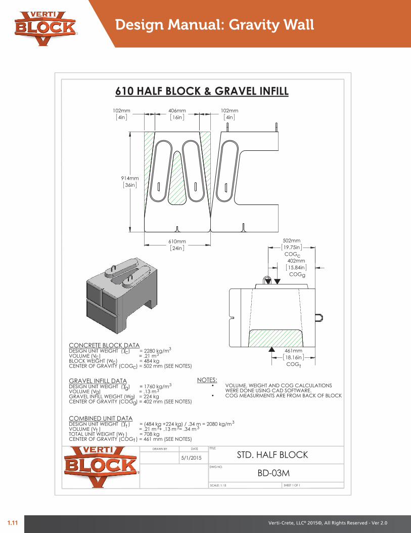
461mm18.16inCOG
COG15.84in402mm
502mm19.75inCOG
102mm4in
102mm4in
DRAWN BY
STD. HALF BLOCK
BD-03MSHEET 1 OF 1SCALE: 1: 15
DWG NO.
TITLE:DATE
5/1/2015
3
3
VOLUME (V ) = .21 m
t
3
3
33
DESIGN UNIT WEIGHT ( ) = 1760 kg/m
CENTER OF GRAVITY (COG ) = 502 mm (SEE NOTES)BLOCK WEIGHT (W ) = 484 kg
GRAVEL INFILL DATA
DESIGN UNIT WEIGHT ( ) = 2280 kg/m
CENTER OF GRAVITY (COG ) = 461 mm (SEE NOTES)TOTAL UNIT WEIGHT (W ) = 708 kg
DESIGN UNIT WEIGHT ( ) = (484 kg +224 kg) / .34 m = 2080 kg/mVOLUME (V ) = .21 m + .13 m = .34 m3
CENTER OF GRAVITY (COG ) = 402 mm (SEE NOTES)
t
GRAVEL INFILL WEIGHT (W ) = 224 kgVOLUME (V ) = .13 m
610 HALF BLOCK & GRAVEL INFILL
CONCRETE BLOCK DATA
COMBINED UNIT DATA
•
cc
cc
c
gg
gg
g
tt
t
NOTES:VOLUME, WEIGHT AND COG CALCULATIONS•WERE DONE USING CAD SOFTWARE.COG MEASURMENTS ARE FROM BACK OF BLOCK
3
36in914mm
610mm24in
406mm16in
Design Manual: Gravity Wall

Gravity W
all
1.12Verti-Crete, LLC® 2015©, All Rights Reserved - Ver 2.0
1157mm
45 916 "
62mm
2 716 "
324mm12.75inCOG
252mm9.92inCOG
12.07in307mm
COG
610mm24"
1219mm48"
t
VOLUME (V ) = .32 m + .14 m = .46 m
610 CORNER BLOCK & GRAVEL INFILL
TOTAL UNIT WEIGHT (W ) = 953 kgCENTER OF GRAVITY (COG ) = 307 mm (SEE NOTES)
COMBINED UNIT DATA
CENTER OF GRAVITY (COG ) = 324 mm (SEE NOTES)
CONCRETE BLOCK DATA
BLOCK WEIGHT (W ) = 723 kgVOLUME (V ) = .32 mDESIGN UNIT WEIGHT ( ) = 2280 kg/m
3
3
333
3
GRAVEL INFILL DATA
3
GRAVEL INFILL WEIGHT (W ) = 230 kgCENTER OF GRAVITY (COG ) = 252 mm (SEE NOTES)
DESIGN UNIT WEIGHT ( ) = 1760 kg/mVOLUME (V ) = .14 m
•
cc
cc
c
gg
gg
g
tt
t
DESIGN UNIT WEIGHT ( ) = (723 kg + 230 kg) / .46 m = 2070 kg/m
t
3
NOTES:VOLUME, WEIGHT AND COG CALCULATIONS•WERE DONE USING CAD SOFTWARE.COG MEASURMENTS ARE FROM BACK OF BLOCK
3
610mm24"
BD-04M
STD. CORNER (L&R) BLOCK
SHEET 1 OF 1SCALE: 1: 15
DWG NO.
TITLE:DATEDRAWN BY
5/1/2015