Embed Size (px)
Citation preview

ENGLISHITALIANOFRANÇAISDEUTSCH
EN English - Instructions manual
IT Italiano - Manuale di istruzioni
FR Français - Manuel d’instructions
DE Deutsch - Bedienungslanleitung
VERSO, VERSO COMPACT, VERSO POLAR
Side opening polycarbonate housing


EN English - Instructions manual
ENGLISH
VERSO, VERSO COMPACT, VERSO POLAR
Side opening polycarbonate housing


Contents ENGLISH
1 About this manual ......................................................................................................... 51.1 Typographical conventions .................................................................................................................................. 5
2 Notes on copyright and information on trademarks .................................................. 53 Safety rules..................................................................................................................... 54 Identification .................................................................................................................. 6
4.1 Product description and type designation..................................................................................................... 64.1.1 VERSO ........................................................................................................................................................................................... 64.1.2 VERSO COMPACT ..................................................................................................................................................................... 64.1.3 VERSO POLAR ............................................................................................................................................................................ 6
4.2 Product markings .................................................................................................................................................... 65 Preparing the product for use ...................................................................................... 7
5.1 Unpacking and contents ....................................................................................................................................... 75.1.1 Unpacking .................................................................................................................................................................................. 75.1.2 Contents ...................................................................................................................................................................................... 7
5.2 Safely disposing of packaging material ........................................................................................................... 75.3 Preparatory work before installation ................................................................................................................ 7
5.3.1 Attaching the support ........................................................................................................................................................... 7
6 Assembling and installing ............................................................................................ 86.1 Installation .................................................................................................................................................................. 8
6.1.1 How to open the housing ..................................................................................................................................................... 86.1.2 How to install the camera ..................................................................................................................................................... 86.1.3 Board description .................................................................................................................................................................... 96.1.4 Connection of the power supply line .............................................................................................................................11
6.1.4.1 Type of cable .................................................................................................................................................................................................11
6.1.5 Installation of the version with double filter for air renewal ..................................................................................116.1.6 Desiccant bag .........................................................................................................................................................................11
7 Accessories ................................................................................................................... 127.1 Heater .........................................................................................................................................................................12
7.1.1 Heater installation .................................................................................................................................................................12
7.2 Camera power supply ..........................................................................................................................................127.2.1 Camera power supply installation ...................................................................................................................................12
7.3 Blower ........................................................................................................................................................................137.3.1 Blower installation .................................................................................................................................................................13
8 Maintaining and cleaning ........................................................................................... 138.1 Window and plastic cover cleaning ................................................................................................................13
9 Disposal of waste materials ........................................................................................ 1310 Technical data ............................................................................................................ 14
10.1 VERSO ......................................................................................................................................................................1410.1.1 General ....................................................................................................................................................................................1410.1.2 Mechanical ............................................................................................................................................................................1410.1.3 Electrical .................................................................................................................................................................................1410.1.4 Environment .........................................................................................................................................................................14
10.1.5 Certifications .........................................................................................................................................................................14
10.2 VERSO COMPACT .................................................................................................................................................1510.2.1 General ....................................................................................................................................................................................1510.2.2 Mechanical ............................................................................................................................................................................1510.2.3 Electrical .................................................................................................................................................................................1510.2.4 Environment .........................................................................................................................................................................1510.2.5 Certifications .........................................................................................................................................................................15
10.3 VERSO POLAR ........................................................................................................................................................1610.3.1 General ....................................................................................................................................................................................1610.3.2 Mechanical ............................................................................................................................................................................1610.3.3 Electrical .................................................................................................................................................................................1610.3.4 Environment .........................................................................................................................................................................1610.3.5 Certifications .........................................................................................................................................................................16
11 Technical drawings .................................................................................................... 17
Instructions m
anual - English - EN
5MNVCHPVB_1351_EN
1 About this manualBefore installing and using this unit, please read this manual carefully. Be sure to keep it handy for later reference.
1.1 Typographical conventions
DANGER! High level hazard. Risk of electric shock. Disconnect the power supply before proceeding with any operation, unless indicated otherwise.
WARNING! Medium level hazard. This operation is very important for the system to function properly. Please read the procedure described very carefully and carry it out as instructed.
INFO Description of system specifications. We recommend reading this part carefully in order to understand the subsequent stages.
2 Notes on copyright and information on trademarksThe quoted names of products or companies are trademarks or registered trademarks.
3 Safety rules• The manufacturer declines all responsibility
for any damage caused by an improper use of the appliances mentioned in this manual. Furthermore, the manufacturer reserves the right to modify its contents without any prior notice. The documentation contained in this manual has been collected with great care, the manufacturer, however, cannot take any liability for its use. The same thing can be said for any person or company involved in the creation and production of this manual.
• The device must be installed only and exclusively by qualified technical personnel.
• Before starting any operation, make sure the power supply is disconnected.
• Do not use cables that seem worn or old.
• Never, under any circumstances, make any changes or connections that are not shown in this handbook. Improper use of the appliance can cause serious hazards, risking the safety of personnel and of the installation.
• Use only original spare parts. Non-original spare parts could cause fire, electrical discharge or other hazards.
• Before proceeding with installation check the supplied material to make sure it corresponds to the order specification by examining the identification labels (4.2 Product markings, page 6).
• This device was designed to be permanently installed on a building or on a suitable structure. The device must be installed permanently before any operation.
• When installing the device, comply with all the national standards.
• The electrical system to which the unit is connected must be equipped with a automatic bipolar circuit breaker. The circuit breaker for main supply voltage phase units must have a level of intervention of 20A max. The circuit breaker for low voltage units must have a level of intervention of 6A max. This circuit breaker must be of the Listed type. The minimum distance between the contacts must be 3mm (0.1in). The circuit breaker must be provided with protection against the fault current towards the ground (differential) and the overcurrent (magnetothermal).
EN -
Engl
ish
- Ins
truc
tions
man
ual
6 MNVCHPVB_1351_EN
• Any device which could be installed inside the product must comply with the current safety standards.
• If the installation is NEMA TYPE 4X, the installer must replace the cable glands of the product with NEMA TYPE 4X cable glands.
• For all connections, use cables that are able to withstand temperatures of at least 75°C (167°F).
• The product is designed to house only cameras that are properly certified (7W max).
• A disconnecting device, readily and easily accessible, must be incorporated in the electrical system of the building for rapid intervention.
• Installation category (also called Overvoltage Category) specifies the level of mains voltage surges that the equipment will be subjected to. The category depends upon the location of the equipment, and on any external surge protection provided. Equipment in an industrial environment, directly connected to major feeders/short branch circuits, is subjected to Installation Category III. If this is the case, a reduction to Installation Category II is required. This can be achieved by use of an insulating transformer with an earthed screen between primary and secondary, or by fitting listed Surge Protective Devices (SPDs) from live to neutral and from neutral to earth. Listed SPDs shall be designed for repeated limiting of transient voltage surges, suitable rated for operating voltage and designated as follows: Type 2 (Permanently connected SPDs intended for installation on the load side of the service equipment overcurrent device); Nominal Discharge Current (In) 20kA min. For example: FERRAZ SHAWMUT, STT2240SPG-CN, STT2BL240SPG-CN rated 120Vac/240Vac, (In=20kA). Maximum distance between installation and reduction is 5m.
• To connect the power supply line use the appropriate junction-box (UPTJBUL). For further information, refer to the product use and installation manual.
• Use Listed copper tube crimping lugs for the connection of the network conductors to the terminals. The copper tube crimping lugs must be suitable for the type of installation (from -20°C (-4°F) to +80°C (+176°F) min., V-0). Copper tube crimping lugs examples: RP, BP or YP (Cembre).
4 Identification4.1 Product description and type designation4.1.1 VERSOIts dimensions make it suitable for a variety of combinations of cameras and lenses.
A specific version with a very efficient cooling system is available for installations with IP cameras and for high environmental temperature.
4.1.2 VERSO COMPACTSturdy tamper-proof housing designed to simplify the installation and service and guarantee total protection against all environmental conditions.
Entirely constructed from technopolymer, it guarantees high impact resistance, high weather protection from external agents and UV rays.
Very easy to install thanks to the side opening system that allows the full access to the camera, lenses and all internal connections.
A wide range of accessories for mounting the equipment is available thereby satisfying all installation needs.
The housing proposes various mounting options, wall or ceiling brackets, feedthrough and non-feedthrough, or Pan & Tilt head.
4.1.3 VERSO POLARThis housing is provided with a high performance heating system which allows the working even at the most severe temperatures, down to-55°C (-67°F).
4.2 Product markingsSee the label attached to the product.
Instructions m
anual - English - EN
7MNVCHPVB_1351_EN
5 Preparing the product for use
Any change that is not expressly approved by the manufacturer will invalidate the guarantee.
5.1 Unpacking and contents5.1.1 UnpackingWhen the product is delivered, make sure that the package is intact and that there are no signs that it has been dropped or scratched.
If there are obvious signs of damage, contact the supplier immediately.
Keep the packaging in case you need to send the product for repairs.
5.1.2 ContentsCheck the contents to make sure they correspond with the list of materials as below:
• Housing
• Housing equipment:
• Allen wrench
• Spacers
• Cable glands gaskets
• Cable glands (x3)
• Bolts and screws
• Screws for camera
• Instructions manual
5.2 Safely disposing of packaging materialThe packaging material can all be recycled. The installer technician will be responsible for separating the material for disposal, and in any case for compliance with the legislation in force where the device is to be used.
When returning a faulty product we recommend using the original packaging for shipping.
5.3 Preparatory work before installation5.3.1 Attaching the support
The product must be fastened with suitable equipment. The fastening means must guarantee the mechanical seal when a force equal to at least 4 times the weight of the device is applied.

EN -
Engl
ish
- Ins
truc
tions
man
ual
8 MNVCHPVB_1351_EN
6 Assembling and installingThe assembly and installation must be performed only by skilled personnel.
6.1 Installation6.1.1 How to open the housingLoosen the 2 screws on the side, turn the cover and the upper half of the body about the opening hinge axis.
Fig. 1
6.1.2 How to install the cameraOpen the housing as described previously (6.1.1 How to open the housing, page 8).
Partially loosening the fastening screws (01).
Remove the internal slide (02) by sliding it until the holes coincide with the slide fastening screws.
Fasten the camera with the 1/4" screw (03). If necessary, use the supplied spacers (04) to correctly position the camera and lenses.
01
0402
03
Fig. 2
Reposition the internal slide and tighten the screws that had been loosened previously.
Remove the conductors protective sheathing and connect them to terminal (camera power supply, 6.1.3 Board description, page 9).
The camera’s power supply cable conductors must be tied up with a cable tie next to the terminal. Keep the signalling and power supply cables separated from each other.

Instructions m
anual - English - EN
9MNVCHPVB_1351_EN
6.1.3 Board description
Connect the safety earth to the relative terminal of the power supply connector.
The board may appear different to that illustrated.
Depending on the product version, the board may not be equipped with all functions.
BOARD DESCRIPTION (VERSO, VERSO COMPACT)
Connector Function
J1 Camera power supply (VOUT)1
Tamper switch contacts2
J2 Heater power supply (VOUT)
J3 Board power supply (VIN)3
J4 Auxiliary output (VOUT)4
J5 Power supply connector/jumper5
J6 Fan power supply (VOUT)
SW1 Tamper switch2
Tab. 1 1 Different alternatives are available depending on the version. VOUT = 12Vdc or VOUT = 24Vac, in relation to the type of power supply installed (7.2.1 Camera power supply installation, page 12). VOUT = VIN, only for hou-sings powered in 12Vdc or 24Vac, with jumper inserted (J5).
2 Optional. Only available for VERSO housing.
3 From 100Vac to 240Vac, 24Vac or12Vdc.
4 Same voltage applied to power supply terminal of the board (J3).
5 To install a power supply in 12Vdc or 24Vac refer to the relative chapter (7.2.1 Camera power supply installa-tion, page 12).
J3J4 J1
J6 SW1J2
J5
Fig. 3 VERSO.
J4 J1J3 J6
J5J2
Fig. 4 VERSO COMPACT.

EN -
Engl
ish
- Ins
truc
tions
man
ual
10 MNVCHPVB_1351_EN
BOARD DESCRIPTION (VERSO, VERSION WITH DOUBLE FILTER FOR AIR RENEWAL)
Connector Function
J1 Board power supply (VIN)1
J2 Auxiliary output (VOUT)2
J3 Heater power supply (VOUT)
J4 Tamper switch contacts3
J5 Camera power supply (VOUT)4
J7 Power supply connector/jumper5
J8 Fan power supply (VOUT)
SW1 Tamper switch3
Tab. 2 1 From 100Vac to 240Vac, 24Vac or12Vdc.
2 Same voltage applied to power supply terminal of the board (J1).
3 Optional.
4 Different alternatives are available depending on the version. VOUT = 12Vdc or VOUT = 24Vac, in relation to the type of power supply installed (7.2.1 Camera power supply installation, page 12). VOUT = VIN, only for hou-sings powered in 12Vdc or 24Vac, with jumper inserted (J7).
5 To install a power supply in 12Vdc or 24Vac refer to the relative chapter (7.2.1 Camera power supply installa-tion, page 12).
J1J4 J2 J8
J7 SW1J3J5
Fig. 5 VERSO (version with double filter for air renewal).
BOARD DESCRIPTION (VERSO POLAR)
Connector Function
J1, J2, J3 Heater power supply (VOUT)
J6 Camera power supply (VOUT)1
J7 Board power supply (VIN)2
J8 Power supply connector/jumper3
J10 Auxiliary output (VOUT)4
Tab. 3 1 Different alternatives are available depending on the version. VOUT = 12Vdc or VOUT = 24Vac, in relation to the type of power supply installed (7.2.1 Camera power supply installation, page 12). VOUT = VIN, only for hou-sings powered in 12Vdc or 24Vac, with jumper inserted (J8).
2 From 100Vac to 240Vac, 24Vac or12Vdc.
3 To install a power supply in 12Vdc or 24Vac refer to the relative chapter (7.2.1 Camera power supply installa-tion, page 12).
4 Same voltage applied to power supply terminal of the board (J7).
J6
J10 J7 J1 J2
J3 J8
Fig. 6 VERSO POLAR.

Instructions m
anual - English - EN
11MNVCHPVB_1351_EN
6.1.4 Connection of the power supply line
Earth cable should be about 10mm longer than the other two, so that it will not be disconnected accidentally if pulled.
Insert the cables for the connection to the power supply line inside the housing through the cable glands. The cable glands are suitable for conductors with diameters of between 5mm and 10mm. The section of the cable inside the housing must be sufficiently long to allow connection. Suitably lock the cable glands.
Remove the conductors protective sheathing and connect them to terminal (board power supply, 6.1.3 Board description, page 9).
6.1.4.1 Type of cableThe cable used for the connection to the power supply line must be suitable for the intended use. Comply with the current national standards on electrical installations.
6.1.5 Installation of the version with double filter for air renewal
During installation pay attention to the orientation of the air inlet filter fins.
Fig. 7
Depending on the angle of inclination of the housing, the orientation of the filter fins must prevent water penetrating in case of rain:
To guarantee the weatherproof, install the housing on the support following the inclination limits as shown in the picture.
45°
45°
0˚
Fig. 8 Maximum tilt of the transversal axis: 0°. Maximum tilt of the longitudinal axis: ±45°.
6.1.6 Desiccant bagTake the dessicant salt bag out of its pack and insert it into the product.

EN -
Engl
ish
- Ins
truc
tions
man
ual
12 MNVCHPVB_1351_EN
7 AccessoriesFor further details on configuration and use, refer to the relative manual.
7.1 Heater7.1.1 Heater installationOpen the housing as described previously (6.1.1 How to open the housing, page 8).
Fix the heater kit to the prearranged points on the body of the housing.
The pre-wired heating element (01) should be positioned between the 2 dissipators (02) before attachment to ensure contact and hence guarantee correct heat transmission.
02
01 02
Fig. 9
Pass the heating wiring into the provided seatings.
Fig. 10
Reposition the internal slide.
Close the housing.
7.2 Camera power supply7.2.1 Camera power supply installation
Pay attention to the voltage value used when the circuit is powered. Depending on requirements use the correct power supply kit.
There are 2 types of camera power supply depending on requirements.
Fig. 11 VIN from 100Vac to 240Vac, VOUT 12Vdc.
Fig. 12 VIN 230Vac, VOUT 24Vac.
Open the housing as described previously (6.1.1 How to open the housing, page 8).
Position the camera power supply in the provided seating, parallel to the support ribs. Fix the power supply to the body of the housing using the corner bracket and screws supplied in the camera power supply kit.
Fig. 13

Instructions m
anual - English - EN
13MNVCHPVB_1351_EN
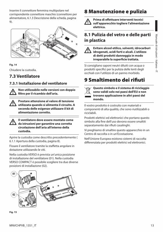
Plug the multipolar female connector into the corresponding male connector (power supply connector, 6.1.3 Board description, page 9).
Fig. 14
Close the housing.
7.3 Blower7.3.1 Blower installation
Not usable in versions with double filter for air renewal.
Pay attention to the voltage value used when the circuit is powered. Depending on requirements use the correct power supply kit.
The blower kit should be assembled according to the instructions to ensure a correct air circulation inside the housing.
Open the housing as described previously (6.1.1 How to open the housing, page 8).
Fix the blower using the corner bracket and screws.
The VERSO housing is provided with a single installation location for the blower (01). In VERSO COMPACT housing you can choose between two different installation locations (02).
01
02
Fig. 15
8 Maintaining and cleaningBefore doing any technical work on the device, disconnect the power supply.
8.1 Window and plastic cover cleaning
Avoid ethyl alcohol, solvents, hydrogenated hydrocarbide, strong acid and alkali. Such products may irreparably damage the surface.
Surface dirt should be rinsed away with water and then the window cleaned with a neutral soap diluted with water, or specific products for spectacle lens cleaning. These should be applied with a soft cloth.
9 Disposal of waste materials
This symbol mark and recycle system are applied only to EU countries and not applied to the countries in the other area of the world.
Your product is designed and manufactured with high quality materials and components which can be recycled and reused.
This symbol means that electrical and electronic equipment, at their end-of-life, should be disposed of separately from your household waste.
Please dispose of this equipment at your local Community waste collection or Recycling centre.
In the European Union there are separate collection systems for used electrical and electronic products.
EN -
Engl
ish
- Ins
truc
tions
man
ual
14 MNVCHPVB_1351_EN
10 Technical data10.1 VERSO10.1.1 GeneralEntirely made of technopolymer (polycarbonate)
Sunshield in ABS
RAL9002 Colour
Stainless steel external screws
10.1.2 MechanicalCable glands: 3xM16
Polycarbonate window (WxH): 105x64mm (4.1x2.5in)
Internal usable area (WxH): 70x70mm (2.7x2.7in)
Internal usable length (with or without accessories): 270mm (10.6in)
Unit weight: 1.5kg (3.3lb)
10.1.3 ElectricalPower supply/Current consumption (empty version):
• From 12Vdc to 24Vdc, 1A max
• From 12Vac to 24Vac, 1A max, 50/60Hz
• From 120Vac to 230Vac, 400mA max, 50/60Hz
Power supply/Current consumption (Version with heater, Ton 15°C±3°C (59°F ±5°F), Toff 22°C±3°C (77°F±5°F)):
• From 12Vdc to 24Vdc, 5A max
• From 12Vac to 24Vac, 5A max, 50/60Hz
• From 120Vac to 230Vac, 700mA max, 50/60Hz
Power supply/Current consumption (version with heater fan assistant, continuous duty):
• 12Vdc, 400mA max
• 24Vac, 200mA max, 50/60Hz
• From 100Vac to 240Vac, 40mA max, 50/60Hz (with wide-range power supply)
Power supply/Current consumption (version with blower and thermostat for models with double filter for air renewal, Ton 35°C±3°C (95°F±5°F), Toff 20°C±3°C (71°F±5°F)):
• 12Vdc, 400mA max
• 24Vac, 200mA max, 50/60Hz
Camera power supply:
• VIN from 100Vac to 240Vac, 50/60Hz VOUT 12Vdc, 1A
• VIN 230Vac, 50/60Hz VOUT 24Vac, 400mA, 50/60Hz
10.1.4 EnvironmentIndoor/Outdoor
Operating temperature (with heater): From -20°C (-4°F) to +60°C (140°F)
Very good resistance to the following chemical agents: basics, alcohols, gasses, hydrocarbon
Good resistance: organic and inorganic acids, oils
Low resistance: solvents
10.1.5 CertificationsCE: EN61000-6-3, EN50130-4, EN60950-1, EN60950-22
EN60529 IP66/IP67 (with cable glands)
EN60529 IP66/IP67 (with special gaskets and bracket with internal cable channel)
EN60529 IP55 (with bracket with internal cable channel)
EN60529 IP44 (for models with cooling blower and double filter)
Fire-self extinguish compliance: UL94 V1
Impact resistance: EN62262 IK10

Instructions m
anual - English - EN
15MNVCHPVB_1351_EN
10.2 VERSO COMPACT10.2.1 GeneralEntirely made of technopolymer (polycarbonate)
Sunshield in ABS
RAL9002 Colour
Stainless steel external screws
10.2.2 MechanicalCable glands: 2xM16
Polycarbonate window (WxH): 98x55mm (3.9x2.2in)
Internal usable area (WxH): 63x63mm (2.5x2.5in)
Internal usable length (with or without accessories): 210mm (8.3in)
Unit weight: 1.1kg (2.2lb)
10.2.3 ElectricalPower supply/Current consumption (empty version):
• From 12Vdc to 24Vdc, 1A max
• From 12Vac to 24Vac, 1A max, 50/60Hz
• From 120Vac to 230Vac, 400mA max, 50/60Hz
Power supply/Current consumption (Version with heater, Ton 15°C±3°C (59°F ±5°F), Toff 22°C±3°C (77°F±5°F)):
• From 12Vdc to 24Vdc, 5A max
• From 12Vac to 24Vac, 5A max, 50/60Hz
• From 120Vac to 230Vac, 700mA max, 50/60Hz
Power supply/Current consumption (version with heater fan assistant, continuous duty):
• 12Vdc, 400mA max
• 24Vac, 200mA max, 50/60Hz
• From 100Vac to 240Vac, 40mA max, 50/60Hz (with wide-range power supply)
Camera power supply:
• VIN from 100Vac to 240Vac, 50/60Hz VOUT 12Vdc, 1A
• VIN 230Vac, 50/60Hz VOUT 24Vac, 400mA, 50/60Hz
10.2.4 EnvironmentIndoor/Outdoor
Operating temperature (with heater): From -20°C (-4°F) to +60°C (140°F)
Very good resistance to the following chemical agents: basics, alcohols, gasses, hydrocarbon
Good resistance: organic and inorganic acids, oils
Low resistance: solvents
10.2.5 CertificationsCE: EN61000-6-3, EN50130-4, EN60950-1, EN60950-22
EN60529 IP66/IP67 (with cable glands)
EN60529 IP66/IP67 (with special gaskets and bracket with internal cable channel)
Fire-self extinguish compliance: UL94 V1
Impact resistance: EN62262 IK10

EN -
Engl
ish
- Ins
truc
tions
man
ual
16 MNVCHPVB_1351_EN
10.3 VERSO POLAR10.3.1 GeneralEntirely made of technopolymer (polycarbonate)
Sunshield in ABS
RAL9002 Colour
Stainless steel external screws
10.3.2 MechanicalCable glands: 3xM16 (nickel-plated brass for external connections)
Polycarbonate window (WxH): 105x64mm (4.1x2.5in)
Internal usable area (WxH): 70x70mm (2.7x2.7in)
Internal usable length (with or without accessories): 270mm (10.6in)
Unit weight: 1.5kg (3.3lb)
10.3.3 ElectricalPower supply/Current consumption (Version with heater, Ton 15°C±3°C (59°F ±5°F), Toff 22°C±3°C (77°F±5°F)):
• From 12Vdc to 24Vdc, 5A max
• From 12Vac to 24Vac, 5A max, 50/60Hz
• From 120Vac to 230Vac, 700mA max, 50/60Hz
Camera power supply:
• VIN from 100Vac to 240Vac, 50/60Hz VOUT 12Vdc, 1A
• VIN 230Vac, 50/60Hz VOUT 24Vac, 400mA, 50/60Hz
10.3.4 EnvironmentIndoor/Outdoor
Operating temperature (with heater): From -55°C (-67°F) to +60°C (140°F)
Very good resistance to the following chemical agents: basics, alcohols, gasses, hydrocarbon
Good resistance: organic and inorganic acids, oils
Low resistance: solvents
10.3.5 CertificationsCE: EN61000-6-3, EN50130-4, EN60950-1, EN60950-22
EN60529 IP66/IP67 (with cable glands)
EN60529 IP66/IP67 (with special gaskets and bracket with internal cable channel)
EN60529 IP55 (with bracket with internal cable channel)
Fire-self extinguish compliance: UL94 V1
Impact resistance: EN62262 IK10

Instructions m
anual - English - EN
17MNVCHPVB_1351_EN
11 Technical drawingsThe dimensions of the drawings are in millimetres.
270 70
7077
100
26
156
1510
1 113
466B
BA
A
A - A B - B
USABLEAREAUSABLE AREA
Fig. 16 VERSO.210
400
94 15
135
1894 10
6
63
63
B
B
A
A
A - A B - B
USABLEAREA
USABLE AREA
Fig. 17 VERSO COMPACT.

MNVCHPVB_1351_EN
270 70
70
466
15
156
101 113
B
B
A
A
A - A B - B
USABLEAREAUSABLE AREA USABLEAREAUSABLE AREA
Fig. 18 VERSO POLAR.
Headquarters Italy Videotec S.p.A.Via Friuli, 6 - I-36015 - Schio (VI) ItalyTel. +39 0445 697411 - Fax +39 0445 697414Email: [email protected]
France Videotec France S.à.r.l.Voie du Futur, Zac des Portes - 27100 - Val-de-Reuil, FranceTel. +33 2 32094900 - Fax +33 2 32094901Email: [email protected]
Asia Pacific Videotec (HK) LtdFlat 8, 19/F. - On Dak Industrial Building2-6 Wah Sing Street - Kwai Chung, NT, Hong KongTel. +852 2333 0601 - Fax +852 2311 0026Email: [email protected]
Americas Videotec Security, Inc.35 Gateway Drive, Suite 100 - Plattsburgh, NY 12901 - U.S.A.Tel. +1 518 825 0020 - Fax +1 518 825 0022Email: [email protected] - www.videotec.us
www.videotec.com

IT Italiano - Manuale di istruzioni
ITALIANO
VERSO, VERSO COMPACT, VERSO POLAR
Custodia in policarbonato ad apertura laterale


Sommario ITALIANO
1 Informazioni sul presente manuale ............................................................................. 51.1 Convenzioni tipografiche ..................................................................................................................................... 5
2 Note sul copyright e informazioni sui marchi commerciali ........................................ 53 Norme di sicurezza ........................................................................................................ 54 Identificazione ............................................................................................................... 6
4.1 Descrizione e designazione del prodotto ....................................................................................................... 64.1.1 VERSO ........................................................................................................................................................................................... 64.1.2 VERSO COMPACT ..................................................................................................................................................................... 64.1.3 VERSO POLAR ............................................................................................................................................................................ 6
4.2 Marcatura del prodotto ......................................................................................................................................... 65 Preparazione del prodotto per l'utilizzo ...................................................................... 7
5.1 Disimballaggio e contenuto ................................................................................................................................ 75.1.1 Disimballaggio .......................................................................................................................................................................... 75.1.2 Contenuto .................................................................................................................................................................................. 7
5.2 Smaltimento in sicurezza dei materiali di imballaggio .............................................................................. 75.3 Lavoro preparatorio prima dell’installazione ................................................................................................. 7
5.3.1 Fissaggio del supporto .......................................................................................................................................................... 7
6 Assemblaggio e installazione ....................................................................................... 86.1 Installazione ............................................................................................................................................................... 8
6.1.1 Apertura della custodia ......................................................................................................................................................... 86.1.2 Installazione della telecamera ............................................................................................................................................ 86.1.3 Descrizione della scheda ...................................................................................................................................................... 96.1.4 Collegamento della linea di alimentazione .................................................................................................................11
6.1.4.1 Tipo di cavo ...................................................................................................................................................................................................11
6.1.5 Installazione della versione con doppio filtro per ricambio dell'aria ..................................................................116.1.6 Sacchetto disidratante .........................................................................................................................................................11
7 Accessori ....................................................................................................................... 127.1 Riscaldamento ........................................................................................................................................................12
7.1.1 Installazione del riscaldamento........................................................................................................................................12
7.2 Alimentatore per telecamera ............................................................................................................................127.2.1 Installazione dell’alimentatore per telecamera ..........................................................................................................12
7.3 Ventilatore ................................................................................................................................................................137.3.1 Installazione del ventilatore ..............................................................................................................................................13
8 Manutenzione e pulizia ............................................................................................... 138.1 Pulizia del vetro e delle parti in plastica ........................................................................................................13
9 Smaltimento dei rifiuti ................................................................................................ 1310 Dati tecnici ................................................................................................................. 14
10.1 VERSO ......................................................................................................................................................................1410.1.1 Generale .................................................................................................................................................................................1410.1.2 Meccanica ..............................................................................................................................................................................1410.1.3 Elettrico ...................................................................................................................................................................................1410.1.4 Ambiente ...............................................................................................................................................................................14

10.1.5 Certificazioni .........................................................................................................................................................................14
10.2 VERSO COMPACT .................................................................................................................................................1510.2.1 Generale .................................................................................................................................................................................1510.2.2 Meccanica ..............................................................................................................................................................................1510.2.3 Elettrico ...................................................................................................................................................................................1510.2.4 Ambiente ...............................................................................................................................................................................1510.2.5 Certificazioni .........................................................................................................................................................................15
10.3 VERSO POLAR ........................................................................................................................................................1610.3.1 Generale .................................................................................................................................................................................1610.3.2 Meccanica ..............................................................................................................................................................................1610.3.3 Elettrico ...................................................................................................................................................................................1610.3.4 Ambiente ...............................................................................................................................................................................1610.3.5 Certificazioni .........................................................................................................................................................................16
11 Disegni tecnici ........................................................................................................... 17
M
anuale di istruzioni - Italiano - IT
5MNVCHPVB_1351_IT
1 Informazioni sul presente manualePrima di installare e utilizzare questa unità, leggere attentamente questo manuale. Conservare questo manuale a portata di mano come riferimento futuro.
1.1 Convenzioni tipografiche
PERICOLO! Pericolosità elevata. Rischio di scosse elettriche. Prima di eseguire qualsiasi operazione assicurarsi di togliere tensione al prodotto, salvo diversa indicazione.
ATTENZIONE! Pericolosità media. L'operazione è molto importante per il corretto funzionamento del sistema. Si prega di leggere attentamente la procedura indicata e di eseguirla secondo le modalità previste.
INFO Descrizione delle caratteristiche del sistema. Si consiglia di leggere attentamente per comprendere le fasi successive.
2 Note sul copyright e informazioni sui marchi commercialiI nomi di prodotto o di aziende citati sono marchi commerciali o marchi commerciali registrati appartenenti alle rispettive società.
3 Norme di sicurezza• Il produttore declina ogni responsabilità per
eventuali danni derivanti da un uso improprio delle apparecchiature menzionate in questo manuale. Si riserva inoltre il diritto di modificarne il contenuto senza preavviso. Ogni cura è stata posta nella raccolta e nella verifica della documentazione contenuta in questo manuale, tuttavia il produttore non può assumersi alcuna responsabilità derivante dall'utilizzo della stessa. Lo stesso dicasi per ogni persona o società coinvolta nella creazione e nella produzione di questo manuale.
• L'installazione e la manutenzione del dispositivo deve essere eseguita solo da personale tecnico qualificato.
• Prima di eseguire qualsiasi operazione assicurarsi di togliere tensione al prodotto.
• Non utilizzare cavi con segni di usura o invecchiamento.
• Non effettuare per nessun motivo alterazioni o collegamenti non previsti in questo manuale. L'uso di apparecchi non idonei può portare a gravi pericoli per la sicurezza del personale e dell'impianto.
• Utilizzare solo parti di ricambio originali. Pezzi di ricambio non originali potrebbero causare incendi, scariche elettriche o altri pericoli.
• Prima di procedere con l'installazione controllare che il materiale fornito corrisponda alle specifiche richieste esaminando le etichette di marcatura (4.2 Marcatura del prodotto, pagina 6).
• Questo dispositivo è stato progettato per essere installato in maniera permanente su un edificio o su una struttura adeguata. Il dispositivo deve essere installato in maniera permanente prima di effettuare qualsiasi operazione.
• Si devono rispettare le normative nazionali per l'installazione del dispositivo.
• L’impianto elettrico al quale è collegata l’unità deve essere dotato di un interruttore di protezione bipolare automatico. L'interruttore per le unità a tensione di rete deve avere un livello di intervento di 20A max. L'interruttore per le unità a bassa tensione deve avere un livello di intervento di 6A max. Tale interruttore deve essere di tipo Listed. La distanza minima tra i contatti deve essere di 3mm. L’interruttore deve essere provvisto di protezione contro la corrente di guasto verso terra (differenziale) e la sovracorrente (magnetotermico).

IT -
Italia
no -
Man
uale
di i
stru
zion
i
6 MNVCHPVB_1351_IT
• Ogni dispositivo che può essere installato all’interno del prodotto deve essere conforme alle norme di sicurezza attuali.
• Se l'installazione deve essere di tipo NEMA TYPE 4X, l'installatore deve sostituire i pressacavi del prodotto con dei pressacavi di tipo NEMA TYPE 4X.
• Per tutte le connessioni, utilizzare cavi idonei a sopportare temperature di almeno 75°C.
• Il prodotto è progettato per alloggiare solo telecamere opportunamente certificate (7W max).
• Un dispositivo di scollegamento, prontamente e facilmente accessibile, deve essere incorporato nell'impianto elettrico dell'edificio per un intervento rapido.
• La categoria di installazione (detta anche categoria di sovratensione) specifica i livelli della tensione transitoria di rete alla quale l’apparato è soggetto. La categoria dipende dal luogo di installazione e dalla presenza di dispositivi di protezione contro le sovratensioni. Un dispositivo per ambienti industriali, connesso ai rami principali dell’impianto di alimentazione è soggetto alla categoria di installazione III. Se questo è il caso, è richiesta una riduzione alla categoria II. Ciò può essere ottenuto utilizzando un trasformatore di isolamento con schermatura connessa a terra tra il primario ed il secondario, o tramite l’impiego di dispositivi di protezione contro le sovratensioni (SPD), UL listed, connessi tra la fase ed il neutro a tra il neutro e terra. I dispositivi SPD UL listed, dovranno essere predisposti per limitare sovratensioni transitorie in modo ripetitivo e per la seguenti condizioni nominali di funzionamento: Tipo 2 (Dispositivi SPD connessi permanentemente alla rete di alimentazione, per istallazioni dal lato del carico del dispositivo di servizio); Corrente nominale di scarica (In) 20kA minimi. Si possono utilizzare ad esempio: FERRAZ SHAWMUT, ST23401PG-CN, ST240SPG-CN specificati per 120Vac/240Vac, (In=20kA). La distanza massima tra l'installazione e la riduzione è di 5m.
• Per la connessione della linea di alimentazione utilizzare l’apposita scatola di connessione (UPTJBUL). Per ulteriori informazioni fare riferimento al manuale d’uso ed installazione del prodotto.
• Utilizzare dei capicorda Listed per la connessione dei conduttori di rete ai morsetti. I capicorda devo essere adeguati al tipo di installazione (da -20°C a +80°C min., V-0). Esempi di capicorda: RP, BP o YP (Cembre).
4 Identificazione4.1 Descrizione e designazione del prodotto4.1.1 VERSOLe sue dimensioni la rendono adatta ad alloggiare svariate combinazioni di telecamere ed ottiche.
È disponibile una versione con un sistema di ventilazione altamente efficiente per applicazioni con telecamere IP e per temperature elevate.
4.1.2 VERSO COMPACTRobusta custodia con caratteristiche antivandaliche, progettata per semplificare l’installazione ed il servizio e garantire una protezione totale a tutte le condizioni ambientali.
Costruita interamente con il più nuovo e resistente tecnopolimero, assicura un’elevata resistenza agli impatti e un’alta protezione contro gli agenti atmosferici ed ai raggi UV.
Estremamente semplice da installare, l’apertura laterale facilita ampiamente l’accesso alla telecamera, alle ottiche e a tutte le connessioni interne.
É disponibile un’ampia gamma di accessori di montaggio che permette di soddisfare qualsiasi esigenza di installazione.
La custodia propone diverse varianti di montaggio, supporto a parete o soffitto, con o senza passaggio interno cavi e brandeggio.
4.1.3 VERSO POLARQuesto modello di custodia è equipaggiato di un sistema di riscaldamento potenziato che garantisce un funzionamento ottimale anche alle temperature più rigide, fino a -55°C.
4.2 Marcatura del prodottoVedere l’etichetta posta sul prodotto.

M
anuale di istruzioni - Italiano - IT
7MNVCHPVB_1351_IT
5 Preparazione del prodotto per l'utilizzo
Qualsiasi cambiamento non espressamente approvato dal costruttore fa decadere la garanzia.
5.1 Disimballaggio e contenuto5.1.1 DisimballaggioAlla consegna del prodotto verificare che l'imballo sia integro e non abbia segni evidenti di cadute o abrasioni.
In caso di evidenti segni di danno all'imballo contattare immediatamente il fornitore.
Conservare l'imballo nel caso sia necessario inviare il prodotto in riparazione.
5.1.2 ContenutoControllare che il contenuto sia corrispondente alla lista del materiale sotto elencata:
• Custodia
• Dotazione per custodia:
• Chiave a brugola
• Distanziali
• Guarnizioni per pressacavi
• Pressacavi (x3)
• Viteria
• Viti per telecamera
• Manuale di istruzioni
5.2 Smaltimento in sicurezza dei materiali di imballaggioI materiali d'imballo sono costituiti interamente da materiale riciclabile. Sarà cura del tecnico installatore smaltirli secondo le modalità di raccolta differenziata o comunque secondo le norme vigenti nel Paese di utilizzo.
In caso di restituzione del prodotto malfunzionante è consigliato l'utilizzo dell'imballaggio originale per il trasporto.
5.3 Lavoro preparatorio prima dell’installazione5.3.1 Fissaggio del supporto
Il prodotto deve essere fissato con mezzi adeguati. I mezzi di fissaggio devono garantire la tenuta meccanica applicando una forza pari almeno a 4 volte il peso complessivo dell’apparecchiatura.
IT -
Italia
no -
Man
uale
di i
stru
zion
i
8 MNVCHPVB_1351_IT
6 Assemblaggio e installazione
L'assemblaggio e l'installazione vanno eseguiti solo da personale qualificato.
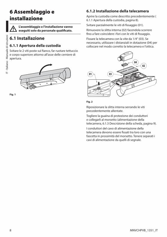
6.1 Installazione6.1.1 Apertura della custodiaSvitare le 2 viti poste sul fianco, far ruotare tettuccio e corpo superiore attorno all’asse delle cerniere di apertura.
Fig. 1
6.1.2 Installazione della telecameraAprire la custodia come descritto precedentemente (6.1.1 Apertura della custodia, pagina 8).
Svitare parzialmente le viti di fissaggio (01).
Rimuovere la slitta interna (02) facendola scorrere fino a fare coincidere i fori con le viti di fissaggio.
Fissare la telecamera con la vite da 1/4" (03). Se necessario, utilizzare i distanziali in dotazione (04) per collocare nel modo corretto la telecamera e l'ottica.
01
0402
03
Fig. 2
Riposizionare la slitta interna serrando le viti precedentemente allentate.
Togliere la guaina di protezione dei conduttori e collegarli al morsetto (alimentazione della telecamera, 6.1.3 Descrizione della scheda, pagina 9).
I conduttori del cavo di alimentazione della telecamera devono essere fissati tra loro con una fascetta in prossimità del morsetto. Tenere separati i cavi di alimentazione da quelli di segnale.
M
anuale di istruzioni - Italiano - IT
9MNVCHPVB_1351_IT
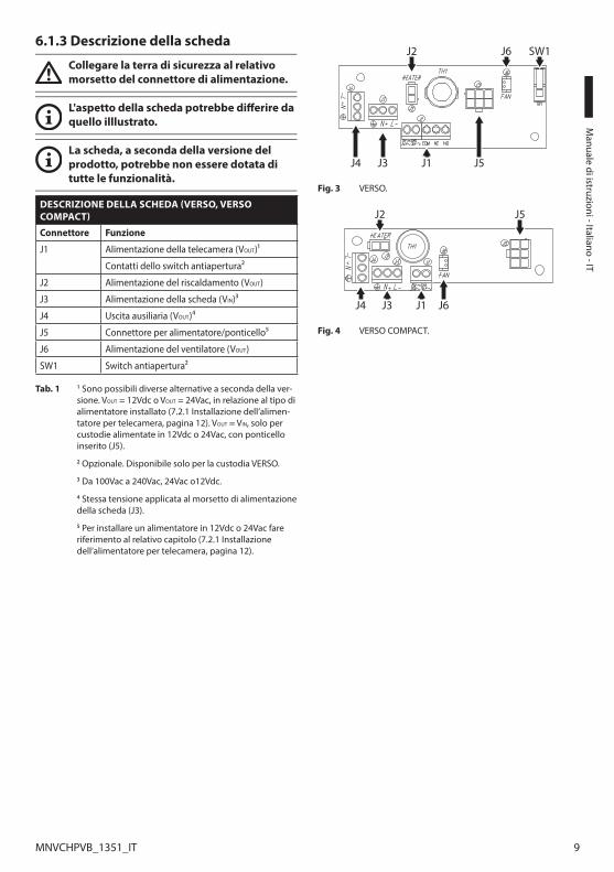
6.1.3 Descrizione della scheda
Collegare la terra di sicurezza al relativo morsetto del connettore di alimentazione.
L'aspetto della scheda potrebbe differire da quello illlustrato.
La scheda, a seconda della versione del prodotto, potrebbe non essere dotata di tutte le funzionalità.
DESCRIZIONE DELLA SCHEDA (VERSO, VERSO COMPACT)
Connettore Funzione
J1 Alimentazione della telecamera (VOUT)1
Contatti dello switch antiapertura2
J2 Alimentazione del riscaldamento (VOUT)
J3 Alimentazione della scheda (VIN)3
J4 Uscita ausiliaria (VOUT)4
J5 Connettore per alimentatore/ponticello5
J6 Alimentazione del ventilatore (VOUT)
SW1 Switch antiapertura2
Tab. 1 1 Sono possibili diverse alternative a seconda della ver-sione. VOUT = 12Vdc o VOUT = 24Vac, in relazione al tipo di alimentatore installato (7.2.1 Installazione dell’alimen-tatore per telecamera, pagina 12). VOUT = VIN, solo per custodie alimentate in 12Vdc o 24Vac, con ponticello inserito (J5).
2 Opzionale. Disponibile solo per la custodia VERSO.
3 Da 100Vac a 240Vac, 24Vac o12Vdc.
4 Stessa tensione applicata al morsetto di alimentazione della scheda (J3).
5 Per installare un alimentatore in 12Vdc o 24Vac fare riferimento al relativo capitolo (7.2.1 Installazione dell’alimentatore per telecamera, pagina 12).
J3J4 J1
J6 SW1J2
J5
Fig. 3 VERSO.
J4 J1J3 J6
J5J2
Fig. 4 VERSO COMPACT.

IT -
Italia
no -
Man
uale
di i
stru
zion
i
10 MNVCHPVB_1351_IT
DESCRIZIONE DELLA SCHEDA (VERSO, VERSIONE CON DOPPIO FILTRO PER IL RICAMBIO DELL'ARIA)
Connettore Funzione
J1 Alimentazione della scheda (VIN)1
J2 Uscita ausiliaria (VOUT)2
J3 Alimentazione del riscaldamento (VOUT)
J4 Contatti dello switch antiapertura3
J5 Alimentazione della telecamera (VOUT)4
J7 Connettore per alimentatore/ponticello5
J8 Alimentazione del ventilatore (VOUT)
SW1 Switch antiapertura3
Tab. 2 1 Da 100Vac a 240Vac, 24Vac o12Vdc.
2 Stessa tensione applicata al morsetto di alimentazione della scheda (J1).
3 Opzionale.
4 Sono possibili diverse alternative a seconda della ver-sione. VOUT = 12Vdc o VOUT = 24Vac, in relazione al tipo di alimentatore installato (7.2.1 Installazione dell’alimen-tatore per telecamera, pagina 12). VOUT = VIN, solo per custodie alimentate in 12Vdc o 24Vac, con ponticello inserito (J7).
5 Per installare un alimentatore in 12Vdc o 24Vac fare riferimento al relativo capitolo (7.2.1 Installazione dell’alimentatore per telecamera, pagina 12).
J1J4 J2 J8
J7 SW1J3J5
Fig. 5 VERSO (versione con doppio filtro per il ricambio dell'a-ria).
DESCRIZIONE DELLA SCHEDA (VERSO POLAR)
Connettore Funzione
J1, J2, J3 Alimentazione del riscaldamento (VOUT)
J6 Alimentazione della telecamera (VOUT)1
J7 Alimentazione della scheda (VIN)2
J8 Connettore per alimentatore/ponticello3
J10 Uscita ausiliaria (VOUT)4
Tab. 3 1 Sono possibili diverse alternative a seconda della ver-sione. VOUT = 12Vdc o VOUT = 24Vac, in relazione al tipo di alimentatore installato (7.2.1 Installazione dell’alimen-tatore per telecamera, pagina 12). VOUT = VIN, solo per custodie alimentate in 12Vdc o 24Vac, con ponticello inserito (J8).
2 Da 100Vac a 240Vac, 24Vac o12Vdc.
3 Per installare un alimentatore in 12Vdc o 24Vac fare riferimento al relativo capitolo (7.2.1 Installazione dell’alimentatore per telecamera, pagina 12).
4 Stessa tensione applicata al morsetto di alimentazione della scheda (J7).
J6
J10 J7 J1 J2
J3 J8
Fig. 6 VERSO POLAR.
M
anuale di istruzioni - Italiano - IT
11MNVCHPVB_1351_IT
6.1.4 Collegamento della linea di alimentazione
Il cavo di terra deve essere più lungo degli altri due di circa 10mm per prevenirne il distacco accidentale a causa dello stiramento.
Introdurre i cavi di collegamento alla linea di alimentazione all'interno della custodia attraverso i pressacavi. I pressacavi sono adatti per conduttori con diametro compreso tra 5mm e 10mm. Il tratto di cavo all'interno della custodia deve essere sufficientemente lungo da permettere il collegamento. Serrare opportunamente i pressacavi.
Togliere la guaina di protezione dei conduttori e collegarli al morsetto (alimentazione della scheda, 6.1.3 Descrizione della scheda, pagina 9).
6.1.4.1 Tipo di cavoIl tipo di cavo da utilizzare per il collegamento alla linea di alimentazione deve essere compatibile con l'impiego previsto. Attenersi alle regole nazionali in vigore riguardo le installazioni elettriche.
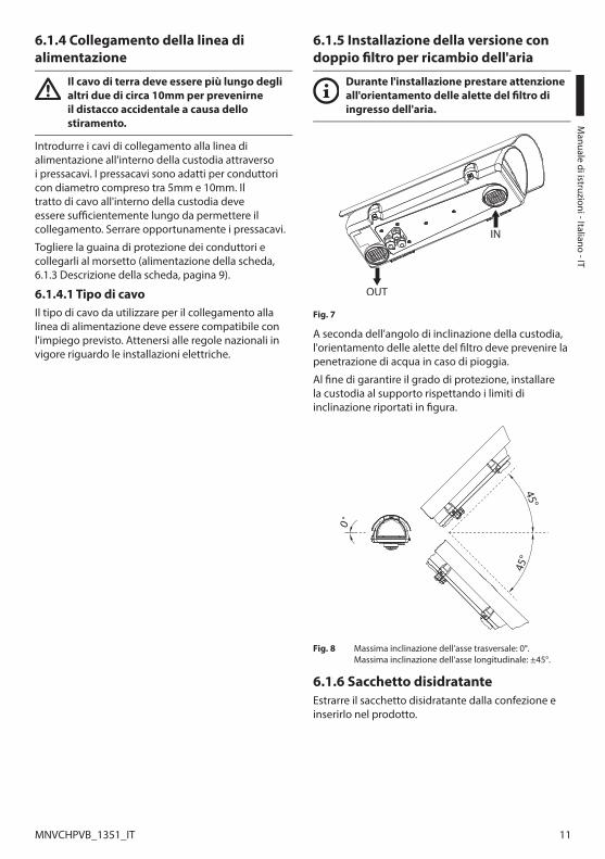
6.1.5 Installazione della versione con doppio filtro per ricambio dell'aria
Durante l'installazione prestare attenzione all'orientamento delle alette del filtro di ingresso dell'aria.
Fig. 7
A seconda dell'angolo di inclinazione della custodia, l'orientamento delle alette del filtro deve prevenire la penetrazione di acqua in caso di pioggia.
Al fine di garantire il grado di protezione, installare la custodia al supporto rispettando i limiti di inclinazione riportati in figura.
45°
45°
0˚
Fig. 8 Massima inclinazione dell'asse trasversale: 0°. Massima inclinazione dell'asse longitudinale: ±45°.
6.1.6 Sacchetto disidratanteEstrarre il sacchetto disidratante dalla confezione e inserirlo nel prodotto.
IT -
Italia
no -
Man
uale
di i
stru
zion
i
12 MNVCHPVB_1351_IT
7 AccessoriPer ulteriori dettagli sulla configurazione e l’utilizzo fare riferimento al manuale del relativo accessorio.
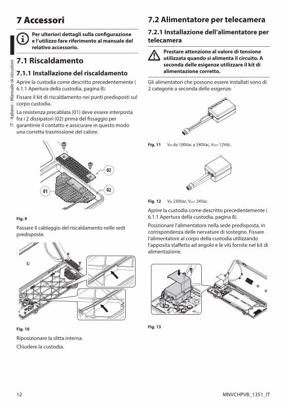
7.1 Riscaldamento7.1.1 Installazione del riscaldamentoAprire la custodia come descritto precedentemente (6.1.1 Apertura della custodia, pagina 8).
Fissare il kit di riscaldamento nei punti predisposti sul corpo custodia.
La resistenza precablata (01) deve essere interposta fra i 2 dissipatori (02) prima del fissaggio per garantirne il contatto e assicurare in questo modo una corretta trasmissione del calore.
02
01 02
Fig. 9
Passare il cablaggio del riscaldamento nelle sedi predisposte.
Fig. 10
Riposizionare la slitta interna.
Chiudere la custodia.
7.2 Alimentatore per telecamera7.2.1 Installazione dell’alimentatore per telecamera
Prestare attenzione al valore di tensione utilizzata quando si alimenta il circuito. A seconda delle esigenze utilizzare il kit di alimentazione corretto.
Gli alimentatori che possono essere installati sono di 2 categorie a seconda delle esigenze.
Fig. 11 VIN da 100Vac a 240Vac, VOUT 12Vdc.
Fig. 12 VIN 230Vac, VOUT 24Vac.
Aprire la custodia come descritto precedentemente (6.1.1 Apertura della custodia, pagina 8).
Posizionare l’alimentatore nella sede predisposta, in corrispondenza delle nervature di sostegno. Fissare l’alimentatore al corpo della custodia utilizzando l’apposita staffetta ad angolo e le viti fornite nel kit di alimentazione.
Fig. 13
M
anuale di istruzioni - Italiano - IT
13MNVCHPVB_1351_IT
Inserire il connettore femmina multipolare nel corrispondente connettore maschio (connettore per alimentatore, 6.1.3 Descrizione della scheda, pagina 9).
Fig. 14
Chiudere la custodia.
7.3 Ventilatore7.3.1 Installazione del ventilatore
Non utilizzabile nelle versioni con doppio filtro per il ricambio dell'aria.
Prestare attenzione al valore di tensione utilizzata quando si alimenta il circuito. A seconda delle esigenze utilizzare il kit di alimentazione corretto.
Il ventilatore deve essere montato come da istruzioni per garantire una corretta circolazione dell’aria all’interno della custodia.
Aprire la custodia come descritto precedentemente (6.1.1 Apertura della custodia, pagina 8).
Fissare il ventilatore tramite la staffetta angolare in dotazione utilizzando le viti.
Nella custodia VERSO è prevista un'unica posizione di installazione del ventilatore (01). Nella custodia VERSO COMPACT è possibile scegliere tra due diverse posizioni di installazione (02).
01
02
Fig. 15
8 Manutenzione e puliziaPrima di effettuare interventi tecnici sull’apparecchio togliere l’alimentazione elettrica.
8.1 Pulizia del vetro e delle parti in plastica
Evitare alcool etilico, solventi, idrocarburi idrogenati, acidi forti e alcali. L’utilizzo di detti prodotti danneggia in modo irreparabile la superficie trattata.
Si consigliano saponi neutri diluiti con acqua o prodotti specifici per la pulizia delle lenti degli occhiali con l’utilizzo di un panno morbido.
9 Smaltimento dei rifiutiQuesto simbolo e il sistema di riciclaggio sono validi solo nei paesi dell'EU e non trovano applicazione in altri paesi del mondo.
Il vostro prodotto è costruito con materiali e componenti di alta qualità, che sono riutilizzabili o riciclabili.
Prodotti elettrici ed elettronici che portano questo simbolo alla fine dell'uso devono essere smaltiti separatamente dai rifiuti casalinghi.
Vi preghiamo di smaltire questo apparecchio in un Centro di raccolta o in un'Ecostazione.
Nell'Unione Europea esistono sistemi di raccolta differenziata per prodotti elettrici ed elettronici.

IT -
Italia
no -
Man
uale
di i
stru
zion
i
14 MNVCHPVB_1351_IT
10 Dati tecnici10.1 VERSO10.1.1 GeneraleCostruita in resistente tecnopolimero (policarbonato)
Tettuccio in ABS
Colore RAL9002
Viteria esterna in acciaio inox
10.1.2 MeccanicaPressacavi: 3xM16
Finestra in policarbonato (WxH): 105x64mm
Dimensioni utili interne (WxH): 70x70mm
Lunghezza utile interna (con o senza accessori): 270mm
Peso unitario: 1.5kg
10.1.3 ElettricoTensione di alimentazione/Corrente assorbita (versione vuota):
• Da 12Vdc a 24Vdc, 1A max
• Da 12Vac a 24Vac, 1A max, 50/60Hz
• Da 120Vac a 230Vac, 400mA max, 50/60Hz
Tensione di alimentazione/Corrente assorbita (versione con riscaldamento, Ton 15°C±3°C, Toff 22°C±3°C):
• Da 12Vdc a 24Vdc, 5A max
• Da 12Vac a 24Vac, 5A max, 50/60Hz
• Da 120Vac a 230Vac, 700mA max, 50/60Hz
Tensione di alimentazione/Corrente assorbita (versione con ventilatore a ciclo continuo per assistenza riscaldamento):
• 12Vdc, 400mA max
• 24Vac, 200mA max, 50/60Hz
• Da 100Vac a 240Vac, 40mA max, 50/60Hz (con alimentatore wide-range)
Tensione di alimentazione/Corrente assorbita (versione con ventilatore e termostato per modelli con doppio filtro per ricambio dell'aria, Ton 35°C±3°C, Toff 20°C±3°C):
• 12Vdc, 400mA max
• 24Vac, 200mA max, 50/60Hz
Alimentatore per telecamera:
• VIN da 100Vac a 240Vac, 50/60Hz VOUT 12Vdc, 1A
• VIN 230Vac, 50/60Hz VOUT 24Vac, 400mA, 50/60Hz
10.1.4 AmbienteInterno/Esterno
Temperatura di esercizio (con riscaldamento): Da -20°C a +60°C
Resistenza molto buona ai seguenti agenti chimici: basi, alcoli, gas, idrocarburi
Resistenza buona: acidi organici e inorganici, olii
Resistenza bassa: solventi
10.1.5 CertificazioniCE: EN61000-6-3, EN50130-4, EN60950-1, EN60950-22
EN60529 IP66/IP67 (con pressacavi)
EN60529 IP66/IP67 (con anelli di tenuta e supporto per passaggio interno cavi)
EN60529 IP55 (con supporto per passaggio interno cavi)
EN60529 IP44 (per modelli con doppio filtro per ricambio d’aria)
Autoestinguenza: UL94 V1
Resistenza agli impatti: EN62262 IK10

M
anuale di istruzioni - Italiano - IT
15MNVCHPVB_1351_IT
10.2 VERSO COMPACT10.2.1 GeneraleCostruita in resistente tecnopolimero (policarbonato)
Tettuccio in ABS
Colore RAL9002
Viteria esterna in acciaio inox
10.2.2 MeccanicaPressacavi: 2xM16
Finestra in policarbonato (WxH): 98x55mm
Dimensioni utili interne (WxH): 63x63mm
Lunghezza utile interna (con o senza accessori): 210mm
Peso unitario: 1.1kg
10.2.3 ElettricoTensione di alimentazione/Corrente assorbita (versione vuota):
• Da 12Vdc a 24Vdc, 1A max
• Da 12Vac a 24Vac, 1A max, 50/60Hz
• Da 120Vac a 230Vac, 400mA max, 50/60Hz
Tensione di alimentazione/Corrente assorbita (versione con riscaldamento, Ton 15°C±3°C, Toff 22°C±3°C):
• Da 12Vdc a 24Vdc, 5A max
• Da 12Vac a 24Vac, 5A max, 50/60Hz
• Da 120Vac a 230Vac, 700mA max, 50/60Hz
Tensione di alimentazione/Corrente assorbita (versione con ventilatore a ciclo continuo per assistenza riscaldamento):
• 12Vdc, 400mA max
• 24Vac, 200mA max, 50/60Hz
• Da 100Vac a 240Vac, 40mA max, 50/60Hz (con alimentatore wide-range)
Alimentatore per telecamera:
• VIN da 100Vac a 240Vac, 50/60Hz VOUT 12Vdc, 1A
• VIN 230Vac, 50/60Hz VOUT 24Vac, 400mA, 50/60Hz
10.2.4 AmbienteInterno/Esterno
Temperatura di esercizio (con riscaldamento): Da -20°C a +60°C
Resistenza molto buona ai seguenti agenti chimici: basi, alcoli, gas, idrocarburi
Resistenza buona: acidi organici e inorganici, olii
Resistenza bassa: solventi
10.2.5 CertificazioniCE: EN61000-6-3, EN50130-4, EN60950-1, EN60950-22
EN60529 IP66/IP67 (con pressacavi)
EN60529 IP66/IP67 (con anelli di tenuta e supporto per passaggio interno cavi)
Autoestinguenza: UL94 V1
Resistenza agli impatti: EN62262 IK10
IT -
Italia
no -
Man
uale
di i
stru
zion
i
16 MNVCHPVB_1351_IT
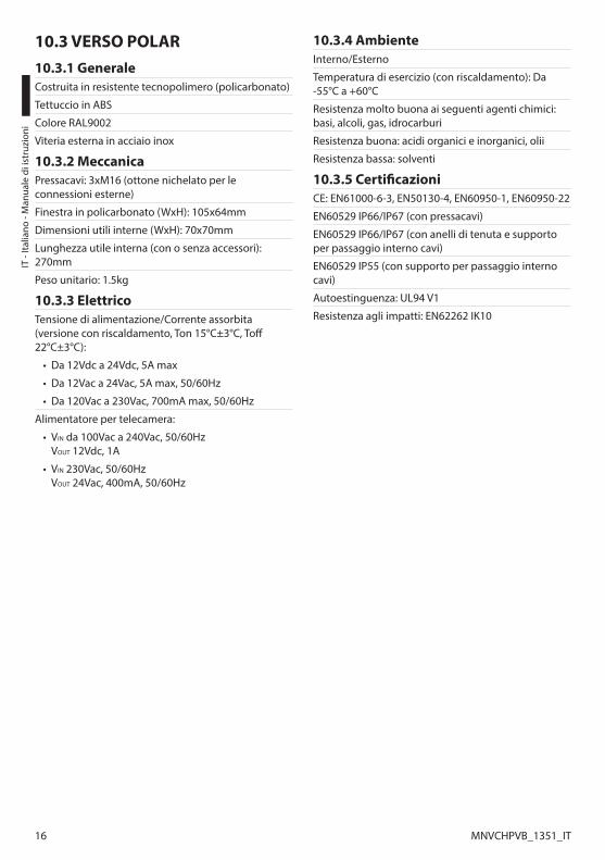
10.3 VERSO POLAR10.3.1 GeneraleCostruita in resistente tecnopolimero (policarbonato)
Tettuccio in ABS
Colore RAL9002
Viteria esterna in acciaio inox
10.3.2 MeccanicaPressacavi: 3xM16 (ottone nichelato per le connessioni esterne)
Finestra in policarbonato (WxH): 105x64mm
Dimensioni utili interne (WxH): 70x70mm
Lunghezza utile interna (con o senza accessori): 270mm
Peso unitario: 1.5kg
10.3.3 ElettricoTensione di alimentazione/Corrente assorbita (versione con riscaldamento, Ton 15°C±3°C, Toff 22°C±3°C):
• Da 12Vdc a 24Vdc, 5A max
• Da 12Vac a 24Vac, 5A max, 50/60Hz
• Da 120Vac a 230Vac, 700mA max, 50/60Hz
Alimentatore per telecamera:
• VIN da 100Vac a 240Vac, 50/60Hz VOUT 12Vdc, 1A
• VIN 230Vac, 50/60Hz VOUT 24Vac, 400mA, 50/60Hz
10.3.4 AmbienteInterno/Esterno
Temperatura di esercizio (con riscaldamento): Da -55°C a +60°C
Resistenza molto buona ai seguenti agenti chimici: basi, alcoli, gas, idrocarburi
Resistenza buona: acidi organici e inorganici, olii
Resistenza bassa: solventi
10.3.5 CertificazioniCE: EN61000-6-3, EN50130-4, EN60950-1, EN60950-22
EN60529 IP66/IP67 (con pressacavi)
EN60529 IP66/IP67 (con anelli di tenuta e supporto per passaggio interno cavi)
EN60529 IP55 (con supporto per passaggio interno cavi)
Autoestinguenza: UL94 V1
Resistenza agli impatti: EN62262 IK10

M
anuale di istruzioni - Italiano - IT
17MNVCHPVB_1351_IT
11 Disegni tecniciLe dimensioni dei disegni sono espresse in millimetri.
270 70
7077
100
26
156
1510
1 113
466B
BA
A
A - A B - B
AREAUTILEAREA UTILE
Fig. 16 VERSO.210
400
94 15
135
1894 10
6
63
63
B
B
A
A
A - A B - B
AREAUTILE
AREA UTILE
Fig. 17 VERSO COMPACT.

MNVCHPVB_1351_IT
270 70
70
466
15
156
101 113
B
B
A
A
A - A B - B
AREAUTILEAREA UTILE
Fig. 18 VERSO POLAR.
Headquarters Italy Videotec S.p.A.Via Friuli, 6 - I-36015 - Schio (VI) ItalyTel. +39 0445 697411 - Fax +39 0445 697414Email: [email protected]
France Videotec France S.à.r.l.Voie du Futur, Zac des Portes - 27100 - Val-de-Reuil, FranceTel. +33 2 32094900 - Fax +33 2 32094901Email: [email protected]
Asia Pacific Videotec (HK) LtdFlat 8, 19/F. - On Dak Industrial Building2-6 Wah Sing Street - Kwai Chung, NT, Hong KongTel. +852 2333 0601 - Fax +852 2311 0026Email: [email protected]
Americas Videotec Security, Inc.35 Gateway Drive, Suite 100 - Plattsburgh, NY 12901 - U.S.A.Tel. +1 518 825 0020 - Fax +1 518 825 0022Email: [email protected] - www.videotec.us
www.videotec.com

FR Français - Manuel d’instructions
FRANÇAIS
VERSO, VERSO COMPACT, VERSO POLAR
Caisson en polycarbonate à ouverture latérale


Sommaire FRANÇAIS
1 À propos de ce mode d’emploi ..................................................................................... 51.1 Conventions typographiques ............................................................................................................................. 5
2 Notes sur le copyright et informations sur les marques de commerce ..................... 53 Normes de securité ........................................................................................................ 54 Identification .................................................................................................................. 6
4.1 Description et désignation du produit ............................................................................................................ 64.1.1 VERSO ........................................................................................................................................................................................... 64.1.2 VERSO COMPACT ..................................................................................................................................................................... 64.1.3 VERSO POLAR ............................................................................................................................................................................ 6
4.2 Marquage du produit ............................................................................................................................................. 65 Préparation du produit en vue de l’utilisation ............................................................ 7
5.1 Déballage et contenu ............................................................................................................................................. 75.1.1 Déballage ................................................................................................................................................................................... 75.1.2 Contenu ...................................................................................................................................................................................... 7
5.2 Élimination sans danger des matériaux d’emballage ................................................................................. 75.3 Opérations à effectuer avant l’installation ...................................................................................................... 7
5.3.1 Fixation du support ................................................................................................................................................................ 7
6 Assemblage et installation ........................................................................................... 86.1 Installation .................................................................................................................................................................. 8
6.1.1 Ouverture du caisson ............................................................................................................................................................. 86.1.2 Installation de la caméra ....................................................................................................................................................... 86.1.3 Description de la carte ........................................................................................................................................................... 96.1.4 Connexion de la ligne d'alimentation ............................................................................................................................11
6.1.4.1 Type de câble ................................................................................................................................................................................................11
6.1.5 Installation de la version avec double filtre pour le changement d'air ..............................................................116.1.6 Sachet déshydratant.............................................................................................................................................................11
7 Accessoires ................................................................................................................... 127.1 Chauffage .................................................................................................................................................................12
7.1.1 Installation du chauffage ....................................................................................................................................................12
7.2 Alimentation pour caméra .................................................................................................................................127.2.1 Installation de l’alimentateur pour caméra ..................................................................................................................12
7.3 Ventilateur ................................................................................................................................................................137.3.1 Installation du ventilateur ..................................................................................................................................................13
8 Entretien et nettoyage ................................................................................................ 138.1 Entretiens de la vitre et des parties en plastique .......................................................................................13
9 Élimination des déchets .............................................................................................. 1310 Données techniques .................................................................................................. 14
10.1 VERSO ......................................................................................................................................................................1410.1.1 Généralités .............................................................................................................................................................................1410.1.2 Mécanique .............................................................................................................................................................................1410.1.3 Électrique ...............................................................................................................................................................................1410.1.4 Environnement ....................................................................................................................................................................14

10.1.5 Certifications .........................................................................................................................................................................14
10.2 VERSO COMPACT .................................................................................................................................................1510.2.1 Généralités .............................................................................................................................................................................1510.2.2 Mécanique .............................................................................................................................................................................1510.2.3 Électrique ...............................................................................................................................................................................1510.2.4 Environnement ....................................................................................................................................................................1510.2.5 Certifications .........................................................................................................................................................................15
10.3 VERSO POLAR ........................................................................................................................................................1610.3.1 Généralités .............................................................................................................................................................................1610.3.2 Mécanique .............................................................................................................................................................................1610.3.3 Électrique ...............................................................................................................................................................................1610.3.4 Environnement ....................................................................................................................................................................1610.3.5 Certifications .........................................................................................................................................................................16
11 Dessins techniques .................................................................................................... 17
M
anuel d'instructions - Français - FR
5MNVCHPVB_1351_FR
1 À propos de ce mode d’emploiAvant d’installer et d’utiliser cet appareil, veuillez lire attentivement ce mode d’emploi. Conservez-le à portée de main pour pouvoir vous y reporter en cas de besoin.
1.1 Conventions typographiques
DANGER! Risque élevé. Risque de choc électrique. Sauf indication contraire, sectionner l'alimentation avant de procéder à toute opération.
ATTENTION! Risque moyen. Opération extrêmement importante en vue d’un fonctionnement correct du système; lire avec attention les opérations indiquées et s’y conformer rigoureusement.
REMARQUE Description des caractéristiques du système. Il est conseillé de procéder à une lecture attentive pour une meilleure compréhension des phases suivantes.
2 Notes sur le copyright et informations sur les marques de commerceLes noms de produit ou de sociétés cités sont des marques de commerce ou des marques de commerce enregistrées.
3 Normes de securité• Le producteur décline toute responsabilité pour
les dommages éventuels dus à une utilisation non appropriée des appareils mentionnés dans ce manuel. On réserve en outre le droit d’en modifier le contenu sans préavis. La documentation contenue dans ce manuel a été rassemblée et vérifiée avec le plus grand soin, cependant, le producteur ne peut pas s’assumer aucune responsabilité dérivante de l’emploi de celle là. La même chose vaut pour chaque personne ou société impliquées dans la création et la production de ce manuel.
• L’installation et l’entretien du dispositif doivent être exclusivement être effectués par un personnel technique qualifié.
• Sectionner l'alimentation avant de procéder à toute opération.
• Ne pas utiliser de câbles usés ou endommagés.
• Ne procéder sous aucun prétexte à des modifications ou des connexions non prévues dans ce manuel. L'utilisation d’appareils non adéquats peut comporter des dangers graves pour la sécurité du personnel et de l’installation.
• Utiliser uniquement des pièces de rechange d’origine. Les pièces non d’origine peuvent être source d’incendies, de choc électrique ou autres.
• Avant de procéder à l’installation, contrôler que le matériel fourni correspond à la commande et examiner les étiquettes de marquage (4.2 Marquage du produit, page 6).
• Cette appareil est conçu pour une installation permanente sur un bâtiment ou une structure adéquate. L'appareil doit être installé d'une façon permanente avant d'effectuer toute opération.
• Il faut respecter les législations nationales pour l'installation du dispositif.
• L'installation électrique à laquelle l'unité est branchée doit être équipée d'un interrupteur de protection bipolaire automatique. L'interrupteur pour les unités a tensione di rete doit avoir un niveau d'intervention de 20A max. L'interrupteur pour les unités à basse tension doit avoir un niveau d'intervention de 6A max. Cet interrupteur doit être de type Listed. La distance minimale entre les contacts doit être de 3mm. L'interrupteur doit être équipé de protection contre le courant de défaut vers la terre (différentiel) et le surintensité (magnétothermique).
FR -
Fran
çais
- M
anue
l d'in
stru
ctio
ns
6 MNVCHPVB_1351_FR
• Chaque appareils pouvant être installés à l'intérieur du produit doivent être conformes aux normes de sécurité en vigueur.
• Si l'installation doit être de type NEMA TYPE 4X, l'installateur devra remplacer les presse-étoupes du produit avec des presse-étoupes de type NEMA TYPE 4X.
• Pour tous les branchements, utiliser les câbles spécifiques pouvant résister à des températures d'au moins 75°C.
• Le projet a été conçu pour ne loger que des caméras dûment certifiées (7W max).
• Un dispositif de déconnexion, rapide et facile d'accès, doit être incorporé dans le circuit électrique du bâtiment pour une intervention rapide.
• La catégorie d’installation (ou catégorie de surtension) spécifie les niveaux de la tension de secteur correspondant à l’appareil. La catégorie dépend du lieu d’installation et du dispositif de protection contre les surtensions installé. En cas d’environnement industriel directement connecté aux circuits de dérivation du système d’alimentation, l’équipement est classé dans la catégorie d’installation III. Dans ce cas, un déclassement à la catégorie II est nécessaire et peut être obtenu au moyen d’un transformateur d’isolement avec blindage électrostatique entre le primaire et le secondaire ou en utilisant des dispositifs de protection contre les surtensions (SPD) entre la phase et le neutre et entre le neutre et la terre. Les dispositifs SPD UL cités doivent être prévus pour limiter les surtensions transitoires en mode répétitif et pour les conditions nominales de fonctionnement suivantes : Type 2 (dispositifs SPD reliés en permanence au côté charge du côté du dispositif de protection contre les surintensités) ; courant nominal de décharge (In) 20kA min. Exemples d’utilisation possible : FERRAZ SHAWMUT, ST23401PG-CN, ST240SPG-CN spécifiés pour 120Vac/240Vca, (In=20kA). La distance maximale entre installation et réduction est de 5m.
• Pour raccorder la ligne d'alimentation utiliser le boîtier de connexion spécifique (UPTJBUL). Pour plus d'informations, se référer au manuel d'utilisation et d'installation du produit.
• Utiliser des cosses Listed pour relier les conducteurs de réseau aux bornes. Les cosses doit être appropriés au type d'installation (de -20°C à +80°C min., V-0). Exemples de cosses: RP, BP ou YP (Cembre).
4 Identification4.1 Description et désignation du produit4.1.1 VERSOSes larges dimensions intérieures lui permettent d’accueillir la plupart des caméras et objectifs du marché.
Une version est disponible avec ventilation forcée, en cas d’installation avec caméras IP et pour températures élevées.
4.1.2 VERSO COMPACTRobuste caisson ayant des caractéristiques anti-vandalismes, conçu pour simplifier l’installation et le service et garantir une protection totale à toutes les conditions environnementales.
Entièrement fabriqué en polycarbonate garantissant ainsi, une grande résistance aux impacts, une excellente protection aux agressions atmosphériques et aux rayons UV.
Très simple à installer, l'ouverture latérale facilite largement l'accès à la caméra, aux optiques et à toutes les connexions internes.
Une vaste gamme d’accessoires de montage est disponible, permettant de solutionner tout problème d’installation.
Le caisson, compatible avec différents types de fixation plafond ou murale, permet le passage des câbles par presse étoupes ou par support creux.
4.1.3 VERSO POLARCe caisson est équipé d’un système de chauffage très performant qui permet le fonctionnement même aux temperatures les plus basses, jusqu’à -55°C.
4.2 Marquage du produitVoir l'étiquette positionné sur le produit.

M
anuel d'instructions - Français - FR
7MNVCHPVB_1351_FR
5 Préparation du produit en vue de l’utilisation
Toute modification non approuvée expressément par le fabricant entraînera l’annulation de la garantie.
5.1 Déballage et contenu5.1.1 DéballageLors de la livraison du produit, vérifier que l’emballage est en bon état et l’absence de tout signe évident de chute ou d’abrasion.
En cas de dommages évidents, contacter immédiatement le fournisseur.
Conserver l’emballage en cas de nécessité d’expédition du produit pour réparation.
5.1.2 ContenuContrôler que le contenu correspond à la liste matériel indiquée ci-dessous:
• Caisson
• Dotation pour caisson:
• Clé Allen
• Entretoises
• Joints pour presse-étoupes
• Presse-étoupes (x3)
• Vis
• Vis pour caméra
• Manuel d'instructions
5.2 Élimination sans danger des matériaux d’emballageLe matériel d’emballage est entièrement composé de matériaux recyclables. Le technicien chargé de l’installation est tenu de l’éliminer conformément aux dispositions en matière de collecte sélective et selon les normes en vigueur dans le pays d’utilisation.
En cas de retour du produit défectueux, il est conseillé d'utiliser l'emballage original pour le transport.
5.3 Opérations à effectuer avant l’installation5.3.1 Fixation du support
Le produit doit être fixé à l'aide des moyens appropriés. Les moyens de fixation doivent garantir l'étanchéité mécanique et appliquer une force égale au moins à 4 fois le poids total de l’appareil.

FR -
Fran
çais
- M
anue
l d'in
stru
ctio
ns
8 MNVCHPVB_1351_FR
6 Assemblage et installation
L’assemblage et l’installation doivent être effectués par un personnel qualifié.
6.1 Installation6.1.1 Ouverture du caissonDévisser les 2 vis placées sur le côté, faire tourner le toit pare-soleil et le corps supérieur autour de l’axe des charnières d’ouverture.
Fig. 1
6.1.2 Installation de la caméraOuvrir le caisson comme décrit précédemment (6.1.1 Ouverture du caisson, page 8).
Dévisser partiellement les vis de fixation (01).
Enlever la glissière interne (02) jusqu’à ce que les trous coïncident avec les vis de fixation.
Fixer la caméra avec la vis de 1/4" (03). Si nécessaire, utiliser les entretoises fournies (04)) pour placer de façon correcte la caméra et l’optique.
01
0402
03
Fig. 2
Replacer la glissière interne en serrant les vis précédemment desserrées.
Enlever la gaine de protection des conducteurs et les brancher à la borne (alimentation de la camera, 6.1.3 Description de la carte, page 9).
Les conducteurs du câble d'alimentation de la caméra doivent être fixés entre eux avec une collier en proximité de la borne. Garder les câbles d'alimentation séparés de ceux de signal.

M
anuel d'instructions - Français - FR
9MNVCHPVB_1351_FR
6.1.3 Description de la carte
Brancher la terre de sécurité à la borne correspondante du connecteur d'alimentation.
L'aspect de la carte pourrait être différer de celui qui est illustré.
La carte, selon la version du produit, pourrait ne pas être munie de toutes les fonctions.
DESCRIPTION DE LA CARTE (VERSO, VERSO COMPACT)
Connecteur Fonction
J1 Alimentation de la camera (VOUT)1
Contact du switch antiapertura?2
J2 Alimentation du chauffage (VOUT)
J3 Alimentation de la carte (VIN)3
J4 Sortie auxiliaire (VOUT)4
J5 Connecteur pour alimentation/barrette5
J6 Alimentation du ventilateur (VOUT)
SW1 Switch anti-ouverture2
Tab. 1 1 Il existe différentes alternatives selon la version. VOUT = 12Vdc ou VOUT = 24Vac, en relation au type d'alimenta-teur installé (7.2.1 Installation de l’alimentateur pour caméra, page 12). VOUT = VIN, uniquement pour les gaines alimentées en 12Vdc ou 24Vac, avec le shunt inséré (J5).
2 En option. Disponible uniquement pour le caisson VERSO.
3 De 100Vac à 240Vac, 24Vac ou12Vdc.
4 Meme tension appliquée à la borne d'alimentation de la carte (J3).
5 Pour installer un alimentateur en 12Vdc ou 24Vac faire référence au chapitre correspondant (7.2.1 Installation de l’alimentateur pour caméra, page 12).
J3J4 J1
J6 SW1J2
J5
Fig. 3 VERSO.
J4 J1J3 J6
J5J2
Fig. 4 VERSO COMPACT.

FR -
Fran
çais
- M
anue
l d'in
stru
ctio
ns
10 MNVCHPVB_1351_FR
DESCRIPTION DE LA CARTE (VERSO, VERSION AVEC DOUBLE FILTRE POUR LE CHANGEMENT D'AIR)
Connecteur Fonction
J1 Alimentation de la carte (VIN)1
J2 Sortie auxiliaire (VOUT)2
J3 Alimentation du chauffage (VOUT)
J4 Contact du switch antiapertura?3
J5 Alimentation de la camera (VOUT)4
J7 Connecteur pour alimentation/barrette5
J8 Alimentation du ventilateur (VOUT)
SW1 Switch anti-ouverture3
Tab. 2 1 De 100Vac à 240Vac, 24Vac ou12Vdc.
2 Meme tension appliquée à la borne d'alimentation de la carte (J1).
3 En option.
4 Il existe différentes alternatives selon la version. VOUT = 12Vdc ou VOUT = 24Vac, en relation au type d'alimenta-teur installé (7.2.1 Installation de l’alimentateur pour caméra, page 12). VOUT = VIN, uniquement pour les gaines alimentées en 12Vdc ou 24Vac, avec le shunt inséré (J7).
5 Pour installer un alimentateur en 12Vdc ou 24Vac faire référence au chapitre correspondant (7.2.1 Installation de l’alimentateur pour caméra, page 12).
J1J4 J2 J8
J7 SW1J3J5
Fig. 5 VERSO (version avec double filtre pour le changement d'air).
DESCRIPTION DE LA CARTE (VERSO POLAR)
Connecteur Fonction
J1, J2, J3 Alimentation du chauffage (VOUT)
J6 Alimentation de la camera (VOUT)1
J7 Alimentation de la carte (VIN)2
J8 Connecteur pour alimentation/barrette3
J10 Sortie auxiliaire (VOUT)4
Tab. 3 1 Il existe différentes alternatives selon la version. VOUT = 12Vdc ou VOUT = 24Vac, en relation au type d'alimenta-teur installé (7.2.1 Installation de l’alimentateur pour caméra, page 12). VOUT = VIN, uniquement pour les gaines alimentées en 12Vdc ou 24Vac, avec le shunt inséré (J8).
2 De 100Vac à 240Vac, 24Vac ou12Vdc.
3 Pour installer un alimentateur en 12Vdc ou 24Vac faire référence au chapitre correspondant (7.2.1 Installation de l’alimentateur pour caméra, page 12).
4 Meme tension appliquée à la borne d'alimentation de la carte (J7).
J6
J10 J7 J1 J2
J3 J8
Fig. 6 VERSO POLAR.
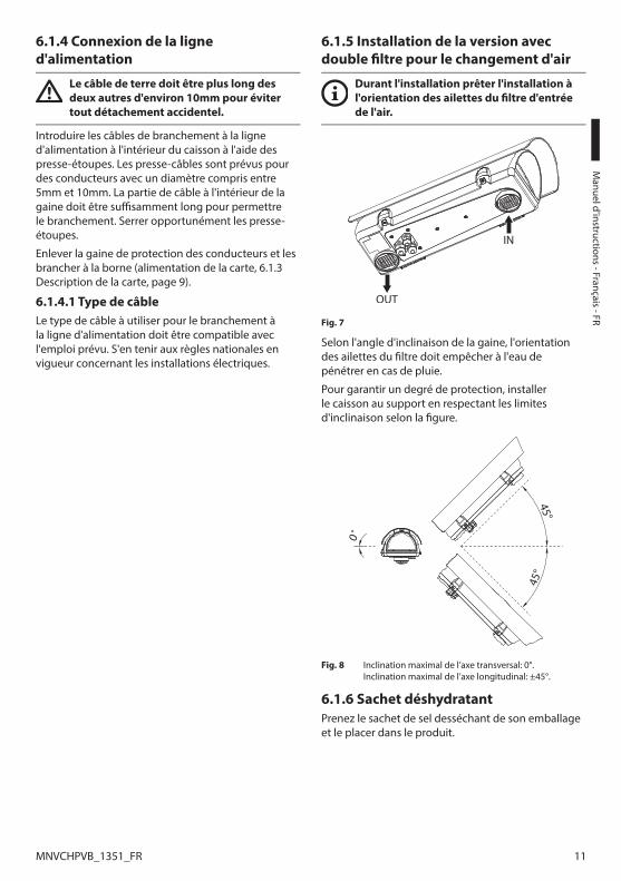
M
anuel d'instructions - Français - FR
11MNVCHPVB_1351_FR
6.1.4 Connexion de la ligne d'alimentation
Le câble de terre doit être plus long des deux autres d'environ 10mm pour éviter tout détachement accidentel.
Introduire les câbles de branchement à la ligne d'alimentation à l'intérieur du caisson à l'aide des presse-étoupes. Les presse-câbles sont prévus pour des conducteurs avec un diamètre compris entre 5mm et 10mm. La partie de câble à l'intérieur de la gaine doit être suffisamment long pour permettre le branchement. Serrer opportunément les presse-étoupes.
Enlever la gaine de protection des conducteurs et les brancher à la borne (alimentation de la carte, 6.1.3 Description de la carte, page 9).
6.1.4.1 Type de câbleLe type de câble à utiliser pour le branchement à la ligne d'alimentation doit être compatible avec l'emploi prévu. S'en tenir aux règles nationales en vigueur concernant les installations électriques.
6.1.5 Installation de la version avec double filtre pour le changement d'air
Durant l'installation prêter l'installation à l'orientation des ailettes du filtre d'entrée de l'air.
Fig. 7
Selon l'angle d'inclinaison de la gaine, l'orientation des ailettes du filtre doit empêcher à l'eau de pénétrer en cas de pluie.
Pour garantir un degré de protection, installer le caisson au support en respectant les limites d'inclinaison selon la figure.
45°
45°
0˚
Fig. 8 Inclination maximal de l’axe transversal: 0°. Inclination maximal de l’axe longitudinal: ±45°.
6.1.6 Sachet déshydratantPrenez le sachet de sel desséchant de son emballage et le placer dans le produit.
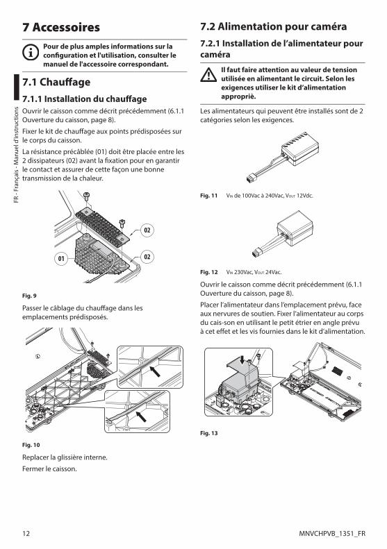
FR -
Fran
çais
- M
anue
l d'in
stru
ctio
ns
12 MNVCHPVB_1351_FR
7 AccessoiresPour de plus amples informations sur la configuration et l'utilisation, consulter le manuel de l'accessoire correspondant.
7.1 Chauffage7.1.1 Installation du chauffageOuvrir le caisson comme décrit précédemment (6.1.1 Ouverture du caisson, page 8).
Fixer le kit de chauffage aux points prédisposées sur le corps du caisson.
La résistance précâblée (01) doit être placée entre les 2 dissipateurs (02) avant la fixation pour en garantir le contact et assurer de cette façon une bonne transmission de la chaleur.
02
01 02
Fig. 9
Passer le câblage du chauffage dans les emplacements prédisposés.
Fig. 10
Replacer la glissière interne.
Fermer le caisson.
7.2 Alimentation pour caméra7.2.1 Installation de l’alimentateur pour caméra
Il faut faire attention au valeur de tension utilisée en alimentant le circuit. Selon les exigences utiliser le kit d’alimentation appropriè.
Les alimentateurs qui peuvent être installés sont de 2 catégories selon les exigences.
Fig. 11 VIN de 100Vac à 240Vac, VOUT 12Vdc.
Fig. 12 VIN 230Vac, VOUT 24Vac.
Ouvrir le caisson comme décrit précédemment (6.1.1 Ouverture du caisson, page 8).
Placer l’alimentateur dans l’emplacement prévu, face aux nervures de soutien. Fixer l’alimentateur au corps du cais-son en utilisant le petit étrier en angle prévu à cet effet et les vis fournies dans le kit d’alimentation.
Fig. 13
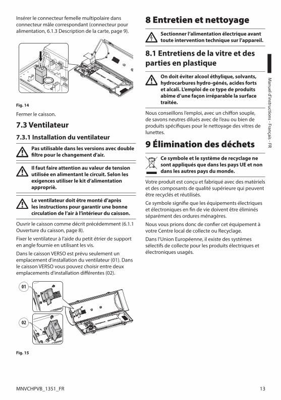
M
anuel d'instructions - Français - FR
13MNVCHPVB_1351_FR
Insérer le connecteur femelle multipolaire dans connecteur mâle correspondant (connecteur pour alimentation, 6.1.3 Description de la carte, page 9).
Fig. 14
Fermer le caisson.
7.3 Ventilateur7.3.1 Installation du ventilateur
Pas utilisable dans les versions avec double filtre pour le changement d'air.
Il faut faire attention au valeur de tension utilisée en alimentant le circuit. Selon les exigences utiliser le kit d’alimentation appropriè.
Le ventilateur doit être monté d’après les instructions pour garantir une bonne circulation de l’air à l’intérieur du caisson.
Ouvrir le caisson comme décrit précédemment (6.1.1 Ouverture du caisson, page 8).
Fixer le ventilateur à l’aide du petit étrier de support en angle fournie en utilisant les vis.
Dans le caisson VERSO est prévu seulement un emplacement d'installation du ventilateur (01). Dans le caisson VERSO vous pouvez choisir entre deux emplacements d'installation différentes (02).
01
02
Fig. 15
8 Entretien et nettoyageSectionner l’alimentation électrique avant toute intervention technique sur l’appareil.
8.1 Entretiens de la vitre et des parties en plastique
On doit éviter alcool éthylique, solvants, hydrocarbures hydro-génés, acides forts et alcali. L’emploi de ce type de produits abîme d’une façon irréparable la surface traitée.
Nous conseillons l’emploi, avec un chiffon souple, de savons neutres dilués avec de l’eau ou bien de produits spécifiques pour le nettoyage des vitres de lunettes.
9 Élimination des déchetsCe symbole et le système de recyclage ne sont appliqués que dans les pays UE et non dans les autres pays du monde.
Votre produit est conçu et fabriqué avec des matèriels et des composants de qualité supérieure qui peuvent être recyclés et réutilisés.
Ce symbole signifie que les équipements électriques et électroniques en fin de vie doivent être éliminés séparément des ordures ménagères.
Nous vous prions donc de confier cet équipement à votre Centre local de collecte ou Recyclage.
Dans l’Union Européenne, il existe des systèmes sélectifs de collecte pour les produits électriques et électroniques usagés.

FR -
Fran
çais
- M
anue
l d'in
stru
ctio
ns
14 MNVCHPVB_1351_FR
10 Données techniques10.1 VERSO10.1.1 GénéralitésConstruction en technopolymère de haute résistance (polycarbonate)
Double toit en ABS
Couleur RAL9002
Visserie extérieure en acier inox
10.1.2 MécaniquePresse-étoupes: 3xM16
Fenêtre en polycarbonate (WxH): 105x64mm
Surface intérieure utile (WxH): 70x70mm
Longueur intérieure utile (avec ou sans accessoires): 270mm
Poids net: 1.5kg
10.1.3 ÉlectriqueTension d’alimentation/Courant absorbé (Version vide):
• De 12Vdc à 24Vdc, 1A max
• De 12Vac à 24Vac, 1A max, 50/60Hz
• De 120Vac à 230Vac, 400mA max, 50/60Hz
Tension d’alimentation/Courant absorbé (version avec chauffage, Ton 15°C±3°C, Toff 22°C±3°C):
• De 12Vdc à 24Vdc, 5A max
• De 12Vac à 24Vac, 5A max, 50/60Hz
• De 120Vac à 230Vac, 700mA max, 50/60Hz
Tension d’alimentation/Courant absorbé (version avec ventilateur à cycle continu pour assistance chauffage):
• 12Vdc, 400mA max
• 24Vac, 200mA max, 50/60Hz
• De 100Vac à 240Vac, 40mA max, 50/60Hz (avec alimentation wide-range)
Tension d’alimentation/Courant absorbé (version avec ventilateur et thermostat avec double filtre pour le renouvellement de l’air, Ton 35°C±3°C, Toff 20°C±3°C):
• 12Vdc, 400mA max
• 24Vac, 200mA max, 50/60Hz
Alimentation pour caméra:
• VIN de 100Vac à 240Vac, 50/60Hz VOUT 12Vdc, 1A
• VIN 230Vac, 50/60Hz VOUT 24Vac, 400mA, 50/60Hz
10.1.4 EnvironnementIntérieur/Extérieur
Température de fonctionnement (avec chauffage): De -20°C à +60°C
Très bonne résistance aux agents chimiques suivants: bases, alcools, gaz, hydrocarbures
Bonne résistance: acides organiques et inorganiques, huiles
Basse résistance: solvants
10.1.5 CertificationsCE: EN61000-6-3, EN50130-4, EN60950-1, EN60950-22
EN60529 IP66/IP67 (avec presse-étoupes)
EN60529 IP66/IP67 (avec bagues d’étanchéité et support pour passage interne des câbles)
EN60529 IP55 (avec support pour passage interne des câbles)
EN60529 IP44 (pour les modèles avec ventilateur et double filtre)
Auto-extinction: UL94 V1
Résistance aux impacts: EN62262 IK10

M
anuel d'instructions - Français - FR
15MNVCHPVB_1351_FR
10.2 VERSO COMPACT10.2.1 GénéralitésConstruction en technopolymère de haute résistance (polycarbonate)
Double toit en ABS
Couleur RAL9002
Visserie extérieure en acier inox
10.2.2 MécaniquePresse-étoupes: 2xM16
Fenêtre en polycarbonate (WxH): 98x55mm
Surface intérieure utile (WxH): 63x63mm
Longueur intérieure utile (avec ou sans accessoires): 210mm
Poids net: 1.1kg
10.2.3 ÉlectriqueTension d’alimentation/Courant absorbé (Version vide):
• De 12Vdc à 24Vdc, 1A max
• De 12Vac à 24Vac, 1A max, 50/60Hz
• De 120Vac à 230Vac, 400mA max, 50/60Hz
Tension d’alimentation/Courant absorbé (version avec chauffage, Ton 15°C±3°C, Toff 22°C±3°C):
• De 12Vdc à 24Vdc, 5A max
• De 12Vac à 24Vac, 5A max, 50/60Hz
• De 120Vac à 230Vac, 700mA max, 50/60Hz
Tension d’alimentation/Courant absorbé (version avec ventilateur à cycle continu pour assistance chauffage):
• 12Vdc, 400mA max
• 24Vac, 200mA max, 50/60Hz
• De 100Vac à 240Vac, 40mA max, 50/60Hz (avec alimentation wide-range)
Alimentation pour caméra:
• VIN de 100Vac à 240Vac, 50/60Hz VOUT 12Vdc, 1A
• VIN 230Vac, 50/60Hz VOUT 24Vac, 400mA, 50/60Hz
10.2.4 EnvironnementIntérieur/Extérieur
Température de fonctionnement (avec chauffage): De -20°C à +60°C
Très bonne résistance aux agents chimiques suivants: bases, alcools, gaz, hydrocarbures
Bonne résistance: acides organiques et inorganiques, huiles
Basse résistance: solvants
10.2.5 CertificationsCE: EN61000-6-3, EN50130-4, EN60950-1, EN60950-22
EN60529 IP66/IP67 (avec presse-étoupes)
EN60529 IP66/IP67 (avec bagues d’étanchéité et support pour passage interne des câbles)
Auto-extinction: UL94 V1
Résistance aux impacts: EN62262 IK10

FR -
Fran
çais
- M
anue
l d'in
stru
ctio
ns
16 MNVCHPVB_1351_FR
10.3 VERSO POLAR10.3.1 GénéralitésConstruction en technopolymère de haute résistance (polycarbonate)
Double toit en ABS
Couleur RAL9002
Visserie extérieure en acier inox
10.3.2 MécaniquePresse-étoupes: 3xM16 (laiton nickelé pour les connexions externes)
Fenêtre en polycarbonate (WxH): 105x64mm
Surface intérieure utile (WxH): 70x70mm
Longueur intérieure utile (avec ou sans accessoires): 270mm
Poids net: 1.5kg
10.3.3 ÉlectriqueTension d’alimentation/Courant absorbé (version avec chauffage, Ton 15°C±3°C, Toff 22°C±3°C):
• De 12Vdc à 24Vdc, 5A max
• De 12Vac à 24Vac, 5A max, 50/60Hz
• De 120Vac à 230Vac, 700mA max, 50/60Hz
Alimentation pour caméra:
• VIN de 100Vac à 240Vac, 50/60Hz VOUT 12Vdc, 1A
• VIN 230Vac, 50/60Hz VOUT 24Vac, 400mA, 50/60Hz
10.3.4 EnvironnementIntérieur/Extérieur
Température de fonctionnement (avec chauffage): De -55°C à +60°C
Très bonne résistance aux agents chimiques suivants: bases, alcools, gaz, hydrocarbures
Bonne résistance: acides organiques et inorganiques, huiles
Basse résistance: solvants
10.3.5 CertificationsCE: EN61000-6-3, EN50130-4, EN60950-1, EN60950-22
EN60529 IP66/IP67 (avec presse-étoupes)
EN60529 IP66/IP67 (avec bagues d’étanchéité et support pour passage interne des câbles)
EN60529 IP55 (avec support pour passage interne des câbles)
Auto-extinction: UL94 V1
Résistance aux impacts: EN62262 IK10

M
anuel d'instructions - Français - FR
17MNVCHPVB_1351_FR
11 Dessins techniquesLes dimensions des dessins sont exprimées en millimètres.
270 70
7077
100
26
156
1510
1 113
466B
BA
A
A - A B - B
SURFACEUTILESURFACE UTILE
Fig. 16 VERSO.210
400
94 15
135
1894 10
6
63
63
B
B
A
A
A - A B - B
SURFACEUTILE
SURFACE UTILE
Fig. 17 VERSO COMPACT.

MNVCHPVB_1351_FR
270 70
70
466
15
156
101 113
B
B
A
A
A - A B - B
SURFACEUTILESURFACE UTILESURFACE UTILE
Fig. 18 VERSO POLAR.
Headquarters Italy Videotec S.p.A.Via Friuli, 6 - I-36015 - Schio (VI) ItalyTel. +39 0445 697411 - Fax +39 0445 697414Email: [email protected]
France Videotec France S.à.r.l.Voie du Futur, Zac des Portes - 27100 - Val-de-Reuil, FranceTel. +33 2 32094900 - Fax +33 2 32094901Email: [email protected]
Asia Pacific Videotec (HK) LtdFlat 8, 19/F. - On Dak Industrial Building2-6 Wah Sing Street - Kwai Chung, NT, Hong KongTel. +852 2333 0601 - Fax +852 2311 0026Email: [email protected]
Americas Videotec Security, Inc.35 Gateway Drive, Suite 100 - Plattsburgh, NY 12901 - U.S.A.Tel. +1 518 825 0020 - Fax +1 518 825 0022Email: [email protected] - www.videotec.us
www.videotec.com
DE Deutsch - Bedienungslanleitung
DEUTSCH
VERSO, VERSO COMPACT, VERSO POLAR
Polykarbonat Gehäuse mit Seitenöffnung


Inhaltsverzeichnis DEUTSCH
1 Allgemeines ................................................................................................................... 51.1 Schreibweisen ........................................................................................................................................................... 5
2 Anmerkungen zum Copyright und Informationen zu den Handelsmarken ............. 53 Sicherheitsnormen ........................................................................................................ 54 Identifizierung ............................................................................................................... 6
4.1 Beschreibung und Bezeichnung des Produktes ........................................................................................... 64.1.1 VERSO ........................................................................................................................................................................................... 64.1.2 VERSO COMPACT ..................................................................................................................................................................... 64.1.3 VERSO POLAR ............................................................................................................................................................................ 6
4.2 Kennzeichnung des Produkts.............................................................................................................................. 65 Vorbereitung des Produktes auf den Gebrauch.......................................................... 7
5.1 Entfernen der Verpackung und Inhalt .............................................................................................................. 75.1.1 Entfernen der Verpackung ................................................................................................................................................... 75.1.2 Inhalt ............................................................................................................................................................................................ 7
5.2 Sichere Entsorgung der Verpackungsmaterialien ....................................................................................... 75.3 Auf die Installation vorbereitende Tätigkeiten .............................................................................................. 7
5.3.1 Befestigung der Halterung ................................................................................................................................................... 7
6 Zusammenbau und Installation ................................................................................... 86.1 Installation .................................................................................................................................................................. 8
6.1.1 Öffnung des Schutzgehause ............................................................................................................................................... 86.1.2 Installation der Kamera ......................................................................................................................................................... 86.1.3 Beschreibung der Karte ......................................................................................................................................................... 96.1.4 Anschluss der Stromversorgung ......................................................................................................................................11
6.1.4.1 Kabelart ..........................................................................................................................................................................................................11
6.1.5 Installation der Version mit Doppelfilter für den Luftaustausch ..........................................................................116.1.6 Trockenmittelbeutel .............................................................................................................................................................11
7 Zubehör ........................................................................................................................ 127.1 Heizung .....................................................................................................................................................................12
7.1.1 Installation der Heizung ......................................................................................................................................................12
7.2 Kameranetzteil ........................................................................................................................................................127.2.1 Installation des Netzteil für Kamera ................................................................................................................................12
7.3 Lüfter ..........................................................................................................................................................................137.3.1 Installation des Lüfters.........................................................................................................................................................13
8 Wartung und Reinigung .............................................................................................. 138.1 Reinigung des Glases und der Kunststoffteile ............................................................................................13
9 Müllentsorgungsstellen .............................................................................................. 1310 Technische Daten ....................................................................................................... 14
10.1 VERSO ......................................................................................................................................................................1410.1.1 Allgemeines ..........................................................................................................................................................................1410.1.2 Mechanik ................................................................................................................................................................................1410.1.3 Elektrik.....................................................................................................................................................................................1410.1.4 Umgebung ............................................................................................................................................................................14

10.1.5 Zertifizierungen ...................................................................................................................................................................14
10.2 VERSO COMPACT .................................................................................................................................................1510.2.1 Allgemeines ..........................................................................................................................................................................1510.2.2 Mechanik ................................................................................................................................................................................1510.2.3 Elektrik.....................................................................................................................................................................................1510.2.4 Umgebung ............................................................................................................................................................................1510.2.5 Zertifizierungen ...................................................................................................................................................................15
10.3 VERSO POLAR ........................................................................................................................................................1610.3.1 Allgemeines ..........................................................................................................................................................................1610.3.2 Mechanik ................................................................................................................................................................................1610.3.3 Elektrik.....................................................................................................................................................................................1610.3.4 Umgebung ............................................................................................................................................................................1610.3.5 Zertifizierungen ...................................................................................................................................................................16
11 Technische Zeichnungen........................................................................................... 17
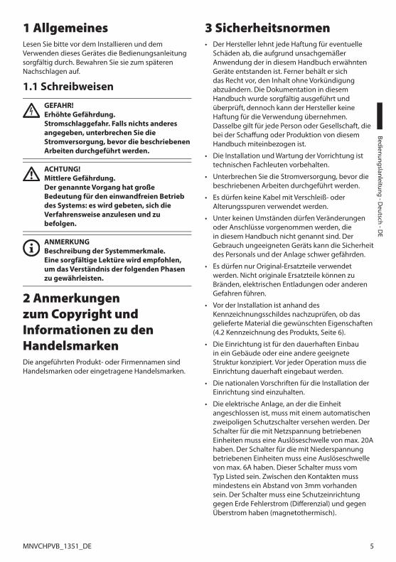
Bedienungslanleitung - D
eutsch - DE
5MNVCHPVB_1351_DE
1 AllgemeinesLesen Sie bitte vor dem Installieren und dem Verwenden dieses Gerätes die Bedienungsanleitung sorgfältig durch. Bewahren Sie sie zum späteren Nachschlagen auf.
1.1 Schreibweisen
GEFAHR! Erhöhte Gefährdung. Stromschlaggefahr. Falls nichts anderes angegeben, unterbrechen Sie die Stromversorgung, bevor die beschriebenen Arbeiten durchgeführt werden.
ACHTUNG! Mittlere Gefährdung. Der genannte Vorgang hat große Bedeutung für den einwandfreien Betrieb des Systems: es wird gebeten, sich die Verfahrensweise anzulesen und zu befolgen.
ANMERKUNG Beschreibung der Systemmerkmale. Eine sorgfältige Lektüre wird empfohlen, um das Verständnis der folgenden Phasen zu gewährleisten.
2 Anmerkungen zum Copyright und Informationen zu den HandelsmarkenDie angeführten Produkt- oder Firmennamen sind Handelsmarken oder eingetragene Handelsmarken.
3 Sicherheitsnormen• Der Hersteller lehnt jede Haftung für eventuelle
Schäden ab, die aufgrund unsachgemäßer Anwendung der in diesem Handbuch erwähnten Geräte entstanden ist. Ferner behält er sich das Recht vor, den Inhalt ohne Vorkündigung abzuändern. Die Dokumentation in diesem Handbuch wurde sorgfältig ausgeführt und überprüft, dennoch kann der Hersteller keine Haftung für die Verwendung übernehmen. Dasselbe gilt für jede Person oder Gesellschaft, die bei der Schaffung oder Produktion von diesem Handbuch miteinbezogen ist.
• Die Installation und Wartung der Vorrichtung ist technischen Fachleuten vorbehalten.
• Unterbrechen Sie die Stromversorgung, bevor die beschriebenen Arbeiten durchgeführt werden.
• Es dürfen keine Kabel mit Verschleiß- oder Alterungsspuren verwendet werden.
• Unter keinen Umständen dürfen Veränderungen oder Anschlüsse vorgenommen werden, die in diesem Handbuch nicht genannt sind. Der Gebrauch ungeeigneten Geräts kann die Sicherheit des Personals und der Anlage schwer gefährden.
• Es dürfen nur Original-Ersatzteile verwendet werden. Nicht originale Ersatzteile können zu Bränden, elektrischen Entladungen oder anderen Gefahren führen.
• Vor der Installation ist anhand des Kennzeichnungsschildes nachzuprüfen, ob das gelieferte Material die gewünschten Eigenschaften (4.2 Kennzeichnung des Produkts, Seite 6).
• Die Einrichtung ist für den dauerhaften Einbau in ein Gebäude oder eine andere geeignete Struktur konzipiert. Vor jeder Operation muss die Einrichtung dauerhaft eingebaut werden.
• Die nationalen Vorschriften für die Installation der Einrichtung sind einzuhalten.
• Die elektrische Anlage, an der die Einheit angeschlossen ist, muss mit einem automatischen zweipoligen Schutzschalter versehen werden. Der Schalter für die mit Netzspannung betriebenen Einheiten muss eine Auslöseschwelle von max. 20A haben. Der Schalter für die mit Niederspannung betriebenen Einheiten muss eine Auslöseschwelle von max. 6A haben. Dieser Schalter muss vom Typ Listed sein. Zwischen den Kontakten muss mindestens ein Abstand von 3mm vorhanden sein. Der Schalter muss eine Schutzeinrichtung gegen Erde Fehlerstrom (Differenzial) und gegen Überstrom haben (magnetothermisch).

DE
- Deu
tsch
- Be
dien
ungs
lanl
eitu
ng
6 MNVCHPVB_1351_DE
• Jede Art in das Produkt installierbares Gerät muss den geltenden Sichereitsnormen genügen.
• Bei einer Installation vom Typ NEMA TYPE 4X müssen die Kabelverschraubungen des Produkts durch Kabelverschraubungen vom Typ NEMA TYPE 4X ersetzt werden.
• Benutzen Sie für alle Verbindungen Kabel, die bis mindestens 75°C hitzebeständig sind.
• Das Produkt kann nur für entsprechend zertifizierte Kameras benutzt werden (7W max).
• Eine sofort und problemlos zugängliche Abtrennvorrichtung muss in die Elektroanlage des Gebäudes eingebaut werden, um einen schnellen Eingriff zu garantieren.
• Die Installationskategorie (auch als Überspannungskategorie bezeichnet) gibt den Pegel der Netzspannungsstöße an, denen die Ausrüstung ausgesetzt ist. Die Kategorie hängt vom Installationsort der Ausrüstung und von den externen Schutzeinrichtungen gegen Spannungsstöße ab. Ausrüstungen in einer gewerblichen Umgebung, die direkt mit den Hauptzweigen der Versorgungsanlage verbunden sind, gehören zur Installationskategorie III. In diesem Fall ist eine Abstufung auf Installationskategorie II erforderlich. Dies kann durch den Einsatz eines Isoliertransformators mit einem geerdeten Schirm zwischen Primär- und Sekundärwicklung erreicht werden. Alternativ können UL-gelistete Überspannungsschutzvorrichtungen (SPD) von Fase zu Nullleiter und von Nullleiter zur Erde geführt werden. UL-gelistete Überspannungsschutzvorrichtungen sind für die wiederholte Begrenzung kurzzeitig auftretender Spannungsspitzen und für die folgenden nominellen Betriebsbedingungen auszulegen: Typ 2 (Dauerhaft angeschlossene Überspannungsschutzvorrichtungen für die Installation auf der Ladungsseite der Hilfseinrichtung); Nennentladestrom (In) 20kA min. Benutzt werden können beispielsweise: FERRAZ SHAWMUT, STT2240SPG-CN, STT2BL240SPG-CN, spezifiziert für 120Vac/240Vac, (In=20kA). Der maximale Abstand zwischen dem Einbau und der Abkürzung ist 5m.
• Für den Anschluss der Versorgungsleitung den entsprechenden Anschlusskasten verwenden (UPTJBUL). Für weitere Informationen siehe Bedienungs- und Installationshandbuch des Produktes.
• Für den Anschluss der Netzleiter an die Klemmen Listed-Kabelschuhe verwenden. Die Kabelschuhe müssen für die Art der Installation geeignet sein. (von -20°C bis +80°C min., V-0). Beispiele für Kabelschuhe: RP, BP oder YP (Cembre).
4 Identifizierung4.1 Beschreibung und Bezeichnung des Produktes4.1.1 VERSODank seinen Abmessungen eignet es sich für eine Vielzahl Kombinationen von Kameras und Optiken.
Es gibt auch eine Version mit einem sehr effizienten Luftrad für Anwendungen mit IP Kamera und für hohe Temperaturen.
4.1.2 VERSO COMPACTRobustes, vandalensicheres Gehäuse, das zur Vereinfachung von Installation und Wartung konstruiert ist und vollständigen Schutz gegen alle Umgebungsbedingungen bietet.
Vollständig aus dem neuesten und widerstandsfähigsten Technoplymer hergestellt, ist es sehr schlagfest und schützt wirksam vor Witterungseinflüssen und UV-Strahlungen.
Äußerst einfache Installation, durch die seitliche Öffnung wird der Zugang zur Videokamera, den Optiken und allen innenliegenden Anschlüssen erleichtert.
Eine große Auswahl an Montagezubehör ist lieferbar, um allen Installationanforderungen zu entsprechen.
das Gehäuse bietet mit der Wandhalterung, der Halterung mit innerer Kabelführung und dem Schwenk-Neige-Kopf mehrere Montagevarianten an.
4.1.3 VERSO POLARDas Gehäse ist mit einem hochleistenden Heizungssystem mitgeliefert, das die Verwendung auch in strengsten Temperaturen bis zu -55°C ermöglicht.
4.2 Kennzeichnung des ProduktsSiehe die Etikett auf dem Produkt.
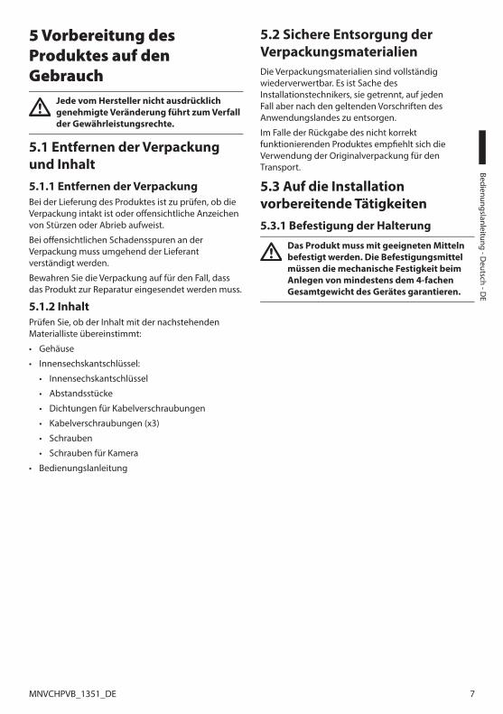
Bedienungslanleitung - D
eutsch - DE
7MNVCHPVB_1351_DE
5 Vorbereitung des Produktes auf den Gebrauch
Jede vom Hersteller nicht ausdrücklich genehmigte Veränderung führt zum Verfall der Gewährleistungsrechte.
5.1 Entfernen der Verpackung und Inhalt5.1.1 Entfernen der VerpackungBei der Lieferung des Produktes ist zu prüfen, ob die Verpackung intakt ist oder offensichtliche Anzeichen von Stürzen oder Abrieb aufweist.
Bei offensichtlichen Schadensspuren an der Verpackung muss umgehend der Lieferant verständigt werden.
Bewahren Sie die Verpackung auf für den Fall, dass das Produkt zur Reparatur eingesendet werden muss.
5.1.2 InhaltPrüfen Sie, ob der Inhalt mit der nachstehenden Materialliste übereinstimmt:
• Gehäuse
• Innensechskantschlüssel:
• Innensechskantschlüssel
• Abstandsstücke
• Dichtungen für Kabelverschraubungen
• Kabelverschraubungen (x3)
• Schrauben
• Schrauben für Kamera
• Bedienungslanleitung
5.2 Sichere Entsorgung der VerpackungsmaterialienDie Verpackungsmaterialien sind vollständig wiederverwertbar. Es ist Sache des Installationstechnikers, sie getrennt, auf jeden Fall aber nach den geltenden Vorschriften des Anwendungslandes zu entsorgen.
Im Falle der Rückgabe des nicht korrekt funktionierenden Produktes empfiehlt sich die Verwendung der Originalverpackung für den Transport.
5.3 Auf die Installation vorbereitende Tätigkeiten5.3.1 Befestigung der Halterung
Das Produkt muss mit geeigneten Mitteln befestigt werden. Die Befestigungsmittel müssen die mechanische Festigkeit beim Anlegen von mindestens dem 4-fachen Gesamtgewicht des Gerätes garantieren.
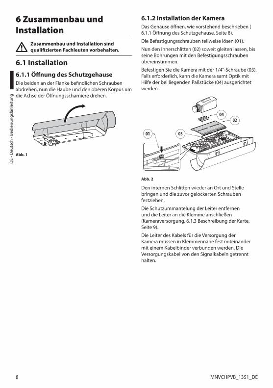
DE
- Deu
tsch
- Be
dien
ungs
lanl
eitu
ng
8 MNVCHPVB_1351_DE
6 Zusammenbau und Installation
Zusammenbau und Installation sind qualifizierten Fachleuten vorbehalten.
6.1 Installation6.1.1 Öffnung des SchutzgehauseDie beiden an der Flanke befindlichen Schrauben abdrehen, nun die Haube und den oberen Korpus um die Achse der Öffnungsscharniere drehen.
Abb. 1
6.1.2 Installation der KameraDas Gehäuse öffnen, wie vorstehend beschrieben (6.1.1 Öffnung des Schutzgehause, Seite 8).
Die Befestigungsschrauben teilweise lösen (01).
Nun den Innerschlitten (02) soweit gleiten lassen, bis seine Bohrungen mit den Befestigungsschrauben übereinstimmen.
Befestigen Sie die Kamera mit der 1/4"-Schraube (03). Falls erforderlich, kann die Kamera samt Optik mit Hilfe der bei liegenden Paßstücke (04) ausgerichtet werden.
01
0402
03
Abb. 2
Den internen Schlitten wieder an Ort und Stelle bringen und die zuvor gelockerten Schrauben festziehen.
Die Schutzummantelung der Leiter entfernen und die Leiter an die Klemme anschließen (Kameraversorgung, 6.1.3 Beschreibung der Karte, Seite 9).
Die Leiter des Kabels für die Versorgung der Kamera müssen in Klemmennähe fest miteinander mit einem Kabelbinder verbunden werden. Die Versorgungskabel von den Signalkabeln getrennt halten.

Bedienungslanleitung - D
eutsch - DE
9MNVCHPVB_1351_DE
6.1.3 Beschreibung der Karte
Den Erdungsschutzleiter an die zugehörige Stromversorgungsklemme anschließen.
Die Abbildung kann von der tatsächlichen Karte abweichen.
Je nach Geräteausführung verfügt die Karte möglicherweise nicht über alle Funktionen.
BESCHREIBUNG DER KARTE (VERSO, VERSO COMPACT)
Verbinder Funktion
J1 Kameraversorgung (VOUT)1
Kontakte des Öffnungsschutzschalters2
J2 Heizungsversorgung (VOUT)
J3 Platinenversorgung (VIN)3
J4 Hilfsausgang (VOUT)4
J5 Verbinder für Netzteil/Überbrückung5
J6 Stromversorgung des Lüfters (VOUT)
SW1 Öffnungssicherer Switch2
Tab. 1 1 Je nach Ausführung sind mehrere Alternativen möglich. VOUT = 12Vdc oder VOUT = 24Vac, je nach Art des installierten Netzteils (7.2.1 Installation des Netzteil für Kamera, Seite 12). VOUT = VIN, nur für mit 12Vdc oder 24Vac versorgte Gehäuse, mit angeschlossener Brücke (J5).
2 Wahlfrei. Nur für VERSO Gehäuse.
3 Von 100Vac bis 240Vac, 24Vac oder12Vdc.
4 Die gleiche Spannung liegt an der Versorgungsklem-me der Platine (J3).
5 Um ein 12V-Gleichstrom- oder 24V-Wechselstrom-Netzteil zu installieren, bitte das entsprechende Kapitel beachten. (7.2.1 Installation des Netzteil für Kamera, Seite 12).
J3J4 J1
J6 SW1J2
J5
Abb. 3 VERSO.
J4 J1J3 J6
J5J2
Abb. 4 VERSO COMPACT.

DE
- Deu
tsch
- Be
dien
ungs
lanl
eitu
ng
10 MNVCHPVB_1351_DE
BESCHREIBUNG DER KARTE (VERSO, AUSFÜHRUNG MIT DOPPELFILTER FÜR DEN LUFTAUSTAUSCH)
Verbinder Funktion
J1 Platinenversorgung (VIN)1
J2 Hilfsausgang (VOUT)2
J3 Heizungsversorgung (VOUT)
J4 Kontakte des Öffnungsschutzschalters3
J5 Kameraversorgung (VOUT)4
J7 Verbinder für Netzteil/Überbrückung5
J8 Stromversorgung des Lüfters (VOUT)
SW1 Öffnungssicherer Switch3
Tab. 2 1 Von 100Vac bis 240Vac, 24Vac oder12Vdc.
2 Die gleiche Spannung liegt an der Versorgungsklem-me der Platine (J1).
3 Wahlfrei.
4 Je nach Ausführung sind mehrere Alternativen möglich. VOUT = 12Vdc oder VOUT = 24Vac, je nach Art des installierten Netzteils (7.2.1 Installation des Netzteil für Kamera, Seite 12). VOUT = VIN, nur für mit 12Vdc oder 24Vac versorgte Gehäuse, mit angeschlossener Brücke (J7).
5 Um ein 12V-Gleichstrom- oder 24V-Wechselstrom-Netzteil zu installieren, bitte das entsprechende Kapitel beachten. (7.2.1 Installation des Netzteil für Kamera, Seite 12).
J1J4 J2 J8
J7 SW1J3J5
Abb. 5 VERSO (Ausführung mit Doppelfilter für den Luftau-stausch).
BESCHREIBUNG DER KARTE (VERSO POLAR)
Verbinder Funktion
J1, J2, J3 Heizungsversorgung (VOUT)
J6 Kameraversorgung (VOUT)1
J7 Platinenversorgung (VIN)2
J8 Verbinder für Netzteil/Überbrückung3
J10 Hilfsausgang (VOUT)4
Tab. 3 1 Je nach Ausführung sind mehrere Alternativen möglich. VOUT = 12Vdc oder VOUT = 24Vac, je nach Art des installierten Netzteils (7.2.1 Installation des Netzteil für Kamera, Seite 12). VOUT = VIN, nur für mit 12Vdc oder 24Vac versorgte Gehäuse, mit angeschlossener Brücke (J8).
2 Von 100Vac bis 240Vac, 24Vac oder12Vdc.
3 Um ein 12V-Gleichstrom- oder 24V-Wechselstrom-Netzteil zu installieren, bitte das entsprechende Kapitel beachten. (7.2.1 Installation des Netzteil für Kamera, Seite 12).
4 Die gleiche Spannung liegt an der Versorgungsklem-me der Platine (J7).
J6
J10 J7 J1 J2
J3 J8
Abb. 6 VERSO POLAR.

Bedienungslanleitung - D
eutsch - DE
11MNVCHPVB_1351_DE
6.1.4 Anschluss der Stromversorgung
Das Erdungskabel muss um etwa 10mm länger sein, als die anderen beiden Kabel, um das ungewollte Lösen durch Ziehen des Kabels zu verhindern.
Die Kabel für den Anschluss an die Versorgungsleitung durch die Kabelverschraubungen ins Gehäuseinnere führen. Die Kabelverschraubungen eignen sich für Leiter mit Durchmesser zwischen 5mm und 10mm. Der Kabelabschnitt im Gehäuse muss ausreichend lang sein, damit der Anschluss möglich ist. Ziehen Sie die Kabelverschraubungen in geeigneter Weisefest.
Die Schutzummantelung der Leiter entfernen und die Leiter an die Klemme anschließen (Platinenversorgung, 6.1.3 Beschreibung der Karte, Seite 9).
6.1.4.1 KabelartDie für den Anschluss an die Versorgungsleitung benutzte Kabelart muss für den vorgesehenen Gebrauch geeignet sein. Beachten Sie die geltenden nationalen Vorschriften bezüglich Elektroinstallationen.
6.1.5 Installation der Version mit Doppelfilter für den Luftaustausch
Während der Installation auf die Ausrichtung der Luftklappen am Lufteinlassfilter achten.
Abb. 7
Je nach Neigungswinkel des Gehäuses müssen die Luftklappen am Filter so ausgerichtet sein, dass bei Regen kein Wasser eindringen kann.
Das Gehäuse auf der Halterung gemäß den Neigungsbegrenzungen des Bildes installieren, um den Schutzgrad zu garantieren.
45°
45°
0˚
Abb. 8 Maximale Neigung der Querachse: 0°. Maximale Neigung der Längsachse: ±45°.
6.1.6 TrockenmittelbeutelNehmen Sie den Trockenmittel- Salzbeutel aus seiner Verpackung und setzen Sie ihn in der Produkt.

DE
- Deu
tsch
- Be
dien
ungs
lanl
eitu
ng
12 MNVCHPVB_1351_DE
7 ZubehörFür weitere Details zur Konfiguration und zum Gebrauch beachten Sie bitte das Handbuch des entsprechenden Geräts.
7.1 Heizung7.1.1 Installation der HeizungDas Gehäuse öffnen, wie vorstehend beschrieben (6.1.1 Öffnung des Schutzgehause, Seite 8).
Reichen Sie den Heizungsdraht durch die vorgesehenen Halterungen.
Der vorverkabelte Heizwiderstand (01) muß, bevor er befestigt wird, zwischen die beiden Ableiter (02) gesetzt werden, damit der Kontakt gewährleistet ist und die Wärme richtig übertragen wird.
02
01 02
Abb. 9
Befestigen Sie die Heizungsverkabelung an den vorgesehenen Stellen des Gehäusekörpers.
Abb. 10
Bringen Sie den internen Schlitten wieder an seine Position.
Das Gehäuse schließen.
7.2 Kameranetzteil7.2.1 Installation des Netzteil für Kamera
Wenn der Schaltkreis gespeist wird, muß auf Versorgungsspannungswert geachtet werden. Verwenden Sie das für den Einzelfall geeignete Netzgerät.
Es lassen sich je nach Bedarf 2 Kategorien von Netzadaptern installieren.
Abb. 11 VIN von 100Vac bis 240Vac, VOUT 12Vdc.
Abb. 12 VIN 230Vac, VOUT 24Vac.
Das Gehäuse öffnen, wie vorstehend beschrieben (6.1.1 Öffnung des Schutzgehause, Seite 8).
Bringen Sie das Netzteil an der vorgesehenen Stelle unter, und zwar in Höhe der Verstärkungs-rippen. Befestigen Sie das Netzgerät mit dem geeigneten Winkeleisen und den bei liegenden Schrauben am Gehäuse -korpus.
Abb. 13
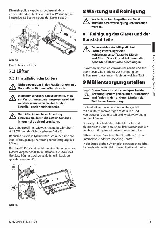
Bedienungslanleitung - D
eutsch - DE
13MNVCHPVB_1351_DE
Die mehrpolige Kupplungsbuchse mit dem entsprechenden Stecker verbinden. (Verbinder für Netzteil, 6.1.3 Beschreibung der Karte, Seite 9).
Abb. 14
Das Gehäuse schließen.
7.3 Lüfter7.3.1 Installation des Lüfters
Nicht anwendbar in den Ausführungen mit Doppelfilter für den Luftaustausch.
Wenn der Schaltkreis gespeist wird, muß auf Versorgungsspannungswert geachtet werden. Verwenden Sie das für den Einzelfall geeignete Netzgerät.
Der Lüfter ist nach der Anleitung einzubauen, damit die Luft im Gehäuse-innern richtig zirkulieren kann.
Das Gehäuse öffnen, wie vorstehend beschrieben (6.1.1 Öffnung des Schutzgehause, Seite 8).
Benutzen Sie die mitgelieferten Schrauben und die winkelförmige Bügelhalterung zur Befestigung des Lüfters.
Bei dem VERSO Gehäuse ist nur eine Einbaulage des Lüfters vorgesehen (01). Bei dem VERSO COMPACT Gehäuse können zwei verschiedene Einbaulagen gewählt werden (01).
01
02
Abb. 15
8 Wartung und ReinigungVor technischen Eingriffen am Gerät muss die Stromversorgung unterbrochen werden.
8.1 Reinigung des Glases und der Kunststoffteile
Zu vermeiden sind Äthylalkohol, Lösungsmittel, hydrierte Kohlenwasserstoffe, starke Säuren und Alkali. Diese Produkte können die behandelte Oberfläche beschädigen.
Es werden empfohlen verwässerte neutrale Seifen oder spezifische Produkte zur Reinigung der Brillenlinsen zusammen mit einem weichen Tuch.
9 MüllentsorgungsstellenDieses Symbol und das entsprechende Recycling-System gelten nur für EULänder und finden in den anderen Ländern der Welt keine Anwendung.
Ihr Produkt wurde entworfen und hergestellt mit qualitativ hochwertigen Materialien und Komponenten, die recycelt und wiederverwendet werden können.
Dieses Symbol bedeutet, daß elektrische und elektronische Geräte am Ende ihrer Nutzungsdauer von Hausmüll getrennt entsorgt werden sollen.
Bitte entsorgen Sie dieses Gerät bei Ihrer örtlichen Sammelstelle oder im Recycling Centre.
In der Europäischen Union gibt es unterschiedliche Sammelsysteme für Elektrik- und Elektronikgeräte.

DE
- Deu
tsch
- Be
dien
ungs
lanl
eitu
ng
14 MNVCHPVB_1351_DE
10 Technische Daten10.1 VERSO10.1.1 AllgemeinesHergestellt aus hochfestem Technopolymer (Polykarbonat)
Sonnenschutzdach aus ABS
Farbe RAL9002
Externe Schrauben aus rostfreiem Stahl
10.1.2 MechanikKabelverschraubungen: 3xM16
Polykarbonat-Fenster (WxH): 105x64mm
Innere Nutzabmessungen (WxH): 70x70mm
Innere Nutzlänge (mit oder ohne Zubehör): 270mm
Einheitsgewicht: 1.5kg
10.1.3 ElektrikVersorgungsspannung/Stromaufnahme (leere Version):
• Von 12Vdc bis 24Vdc, 1A max
• Von 12Vac bis 24Vac, 1A max, 50/60Hz
• Von 120Vac bis 230Vac, 400mA max, 50/60Hz
Versorgungsspannung/Stromaufnahme (Ausführung mit Heizung, Ton 15°C±3°C, Toff 22°C±3°C):
• Von 12Vdc bis 24Vdc, 5A max
• Von 12Vac bis 24Vac, 5A max, 50/60Hz
• Von 120Vac bis 230Vac, 700mA max, 50/60Hz
Versorgungsspannung/Stromaufnahme (Ausführung mit Lüfter im Dauerbetrieb für Heizungshilfe):
• 12Vdc, 400mA max
• 24Vac, 200mA max, 50/60Hz
• Von 100Vac bis 240Vac, 40mA max, 50/60Hz (mit Wide-range Netzteil)
Versorgungsspannung/Stromaufnahme (Version mit Lüfter und Thermostat mit Doppelfilter für Luftwechsel, Ton 35°C±3°C, Toff 20°C±3°C):
• 12Vdc, 400mA max
• 24Vac, 200mA max, 50/60Hz
Kameranetzteil:
• VIN von 100Vac bis 240Vac, 50/60Hz VOUT 12Vdc, 1A
• VIN 230Vac, 50/60Hz VOUT 24Vac, 400mA, 50/60Hz
10.1.4 UmgebungInnen/Außen
Betriebstemperatur (mit Heizung): Von -20°C bis +60°C
Sehr gute Chemikalienbeständigkeit gegen: Basen, Alkohol, Gas, Kohlenwasserstoffe
Gute Beständigkeit: anorganische Säuren, organische Säuren, Öle
Niedrige Beständigkeit: Lösungsmittel
10.1.5 ZertifizierungenCE: EN61000-6-3, EN50130-4, EN60950-1, EN60950-22
EN60529 IP66/IP67 (mit Kabelverschraubungen)
EN60529 IP66/IP67 (mit Dichtungsringe und mit Halterung für innerer Kabelführung)
EN60529 IP55 (mit Halterung mit innerer Kabelführung)
EN60529 IP44 (für Modelle mit Doppelfilter für den Luftwechsel)
Selbstlöschend: UL94 V1
Schlagfestigkeit: EN62262 IK10

Bedienungslanleitung - D
eutsch - DE
15MNVCHPVB_1351_DE
10.2 VERSO COMPACT10.2.1 AllgemeinesHergestellt aus hochfestem Technopolymer (Polykarbonat)
Sonnenschutzdach aus ABS
Farbe RAL9002
Externe Schrauben aus rostfreiem Stahl
10.2.2 MechanikKabelverschraubungen: 2xM16
Polykarbonat-Fenster (WxH): 98x55mm
Innere Nutzabmessungen (WxH): 63x63mm
Innere Nutzlänge (mit oder ohne Zubehör): 210mm
Einheitsgewicht: 1.1kg
10.2.3 ElektrikVersorgungsspannung/Stromaufnahme (leere Version):
• Von 12Vdc bis 24Vdc, 1A max
• Von 12Vac bis 24Vac, 1A max, 50/60Hz
• Von 120Vac bis 230Vac, 400mA max, 50/60Hz
Versorgungsspannung/Stromaufnahme (Ausführung mit Heizung, Ton 15°C±3°C, Toff 22°C±3°C):
• Von 12Vdc bis 24Vdc, 5A max
• Von 12Vac bis 24Vac, 5A max, 50/60Hz
• Von 120Vac bis 230Vac, 700mA max, 50/60Hz
Versorgungsspannung/Stromaufnahme (Ausführung mit Lüfter im Dauerbetrieb für Heizungshilfe):
• 12Vdc, 400mA max
• 24Vac, 200mA max, 50/60Hz
• Von 100Vac bis 240Vac, 40mA max, 50/60Hz (mit Wide-range Netzteil)
Kameranetzteil:
• VIN von 100Vac bis 240Vac, 50/60Hz VOUT 12Vdc, 1A
• VIN 230Vac, 50/60Hz VOUT 24Vac, 400mA, 50/60Hz
10.2.4 UmgebungInnen/Außen
Betriebstemperatur (mit Heizung): Von -20°C bis +60°C
Sehr gute Chemikalienbeständigkeit gegen: Basen, Alkohol, Gas, Kohlenwasserstoffe
Gute Beständigkeit: anorganische Säuren, organische Säuren, Öle
Niedrige Beständigkeit: Lösungsmittel
10.2.5 ZertifizierungenCE: EN61000-6-3, EN50130-4, EN60950-1, EN60950-22
EN60529 IP66/IP67 (mit Kabelverschraubungen)
EN60529 IP66/IP67 (mit Dichtungsringe und mit Halterung für innerer Kabelführung)
Selbstlöschend: UL94 V1
Schlagfestigkeit: EN62262 IK10

DE
- Deu
tsch
- Be
dien
ungs
lanl
eitu
ng
16 MNVCHPVB_1351_DE
10.3 VERSO POLAR10.3.1 AllgemeinesHergestellt aus hochfestem Technopolymer (Polykarbonat)
Sonnenschutzdach aus ABS
Farbe RAL9002
Externe Schrauben aus rostfreiem Stahl
10.3.2 MechanikKabelverschraubungen: 3xM16 (vernickeltem Messing für die Außenanschlüsse)
Polykarbonat-Fenster (WxH): 105x64mm
Innere Nutzabmessungen (WxH): 70x70mm
Innere Nutzlänge (mit oder ohne Zubehör): 270mm
Einheitsgewicht: 1.5kg
10.3.3 ElektrikVersorgungsspannung/Stromaufnahme (Ausführung mit Heizung, Ton 15°C±3°C, Toff 22°C±3°C):
• Von 12Vdc bis 24Vdc, 5A max
• Von 12Vac bis 24Vac, 5A max, 50/60Hz
• Von 120Vac bis 230Vac, 700mA max, 50/60Hz
Kameranetzteil:
• VIN von 100Vac bis 240Vac, 50/60Hz VOUT 12Vdc, 1A
• VIN 230Vac, 50/60Hz VOUT 24Vac, 400mA, 50/60Hz
10.3.4 UmgebungInnen/Außen
Betriebstemperatur (mit Heizung): Von -55°C bis +60°C
Sehr gute Chemikalienbeständigkeit gegen: Basen, Alkohol, Gas, Kohlenwasserstoffe
Gute Beständigkeit: anorganische Säuren, organische Säuren, Öle
Niedrige Beständigkeit: Lösungsmittel
10.3.5 ZertifizierungenCE: EN61000-6-3, EN50130-4, EN60950-1, EN60950-22
EN60529 IP66/IP67 (mit Kabelverschraubungen)
EN60529 IP66/IP67 (mit Dichtungsringe und mit Halterung für innerer Kabelführung)
EN60529 IP55 (mit Halterung mit innerer Kabelführung)
Selbstlöschend: UL94 V1
Schlagfestigkeit: EN62262 IK10

Bedienungslanleitung - D
eutsch - DE
17MNVCHPVB_1351_DE
11 Technische ZeichnungenDie Abmessungen der Zeichnungen sind in Millimeter angegeben.
270 70
7077
100
26
156
1510
1 113
466B
BA
A
A - A B - B
NUTZ-FLÄCHENUTZFLÄCHE
Abb. 16 VERSO.210
400
94 15
135
1894 10
6
63
63
B
B
A
A
A - A B - B
NUTZ-FLÄCHE
NUTZFLÄCHE
Abb. 17 VERSO COMPACT.

MNVCHPVB_1351_DE
270 70
70
466
15
156
101 113
B
B
A
A
A - A B - B
NUTZ-FLÄCHENUTZFLÄCHE NUTZ-FLÄCHENUTZFLÄCHE
Abb. 18 VERSO POLAR.
Headquarters Italy Videotec S.p.A.Via Friuli, 6 - I-36015 - Schio (VI) ItalyTel. +39 0445 697411 - Fax +39 0445 697414Email: [email protected]
France Videotec France S.à.r.l.Voie du Futur, Zac des Portes - 27100 - Val-de-Reuil, FranceTel. +33 2 32094900 - Fax +33 2 32094901Email: [email protected]
Asia Pacific Videotec (HK) LtdFlat 8, 19/F. - On Dak Industrial Building2-6 Wah Sing Street - Kwai Chung, NT, Hong KongTel. +852 2333 0601 - Fax +852 2311 0026Email: [email protected]
Americas Videotec Security, Inc.35 Gateway Drive, Suite 100 - Plattsburgh, NY 12901 - U.S.A.Tel. +1 518 825 0020 - Fax +1 518 825 0022Email: [email protected] - www.videotec.us
www.videotec.com


MNVCHPVB_1351
Headquarters Italy Videotec S.p.A.Via Friuli, 6 - I-36015 - Schio (VI) ItalyTel. +39 0445 697411 - Fax +39 0445 697414Email: [email protected]
France Videotec France S.à.r.l.Voie du Futur, Zac des Portes - 27100 - Val-de-Reuil, FranceTel. +33 2 32094900 - Fax +33 2 32094901Email: [email protected]
Asia Pacific Videotec (HK) LtdFlat 8, 19/F. - On Dak Industrial Building2-6 Wah Sing Street - Kwai Chung, NT, Hong KongTel. +852 2333 0601 - Fax +852 2311 0026Email: [email protected]
Americas Videotec Security, Inc.35 Gateway Drive, Suite 100 - Plattsburgh, NY 12901 - U.S.A.Tel. +1 518 825 0020 - Fax +1 518 825 0022Email: [email protected] - www.videotec.us
www.videotec.com