Embed Size (px)
Citation preview
Electronic Theatre Controls, Inc.
ComposerControlSystem
User’s Guide
Automated Lighting Control System
Version 3.1

CopyrightCopyright © 1997, 1998, 1999 ElectronicTheatre Controls, Inc.
Portions of the software described in thisdocument copyright © Microsoft Corporation.All rights reserved.
Information in this document is subject to changewithout notice. The software described in thisdocument is furnished under a license agreementor nondisclosure agreement. The software maybe used or copied only in accordance with theterms of those agreements. No part of thispublication may be reproduced, stored in aretrieval system, or transmitted in any form orany means electronic or mechanical, includingphotocopying and recording for any purposeother than the purchaser’s use without the writtenpermission of ETC, Inc.
Electronic Theatre Controls, Incorporated3030 Laura LaneMiddleton, WI 53562U.S.A.
TrademarksIrideon® is a registered trademark, and AR5™, AR6™,AR7™, Composer™, and DMX Interpreter™ aretrademarks of ETC, Inc.
Intel is a registered trademark and Pentium is a trademarkof Intel Corporation.
Microsoft and MS-DOS are registered trademarks, andWindows is a trademark of Microsoft Corporation.
All other registered and unregistered trademarks are thesole property of their respective owners.
ETC Document No. 7090M1003Printed in the United States of America

Software License Agreement
By opening the package containing the Composer diskettes andusing the Composer program, the purchaser agrees that the programremains the exclusive property of Electronic Theatre Controls, Inc.and that a personal, non-exclusive license is granted to thepurchaser of the equipment to use the program for the operation ofthe purchased equipment and for no other purpose. A copy of theprogram may be made for backup purposes. The program may notbe reverse engineered, decompiled or disassembled. The creationof derivative works from the program without the written consent ofETC is prohibited. Upon the resale of the equipment only the rightsgranted herein shall be transferred to the purchaser. If you have anyquestions concerning this agreement, please contact ETC at theaddress indicated below.
If you do not agree to the terms of this agreement, do not open thediskette package. Promptly return it unopened to the place whereyou obtained it.
ETC, Incorporated3030 Laura LaneMiddleton, WI 53562U. S. A.

Limited Warranty
ETC, Inc. warrants to Purchaser that for a period of (12) months fromdate of installation, but not more than (18) months from date ofshipment, the Products shall be free from defects in materials andworkmanship under normal use and service. Warranty is limited to(60) days from shipment for sample Products or Products used forrental. ETC, Inc.’s sole responsibility under this warranty shall be torepair or replace, at ETC, Inc.’s option, any nonconsumable partwhich is defective, malfunctions, or otherwise fails to perform itsintended function, when used in a manner consistent with itsintended function, provided that customer obtains return authorizationin advance from ETC, Inc. and ships prepaid any part of the productsto be repaired or replaced under the Limited Warranty to ETC, Inc.or, at ETC, Inc.’s option, to its authorized repair center, within theLimited Warranty period. ETC, Inc. shall not assume anyresponsibility for any labor expended or materials used to repair anyequipment without ETC, Inc.’s prior written authorization. ETC, Inc.’ssole obligations and Purchaser’s sole remedy for any Product that isdefective, malfunctions, or otherwise fails to perform its intendedfunction when used in a manner consistent with its intended functionpursuant to the Limited Warranty is repair and/or replacement of theProduct. ETC, Inc. is not responsible for damage to its productsthrough improper installation, maintenance, use, or attempts tooperate product above its rated capacity or voltage, intentionally orotherwise, or for unauthorized repairs.
TABLE OF CONTENTS v
Table of Contents
IntroductionComposer Hardware Components................................ 1Master Control Processor ................................................. 1Remote Control Stations .................................................. 2
8 Button And 2 Button Recall Stations ..................... 2Receptacle Station..................................................... 2Closure Station.......................................................... 2Key Switch................................................................ 2
Communications............................................................... 3Personal Computer ........................................................... 3Composer Software Components.................................. 3
MCP Operating System............................................. 3PC Application Software........................................... 4
About This Manual ........................................................ 4Organization..................................................................... 4Symbols and Conventions ................................................ 5
Left-Hand Margin ..................................................... 5Tips, Notes, and Cautions ......................................... 5Fonts.......................................................................... 5
Related Documents........................................................... 5ETC, Inc. Applications Guide................................... 5AR5™ Wash Luminaire Owner’s Manual ................ 6AR6™ Recessed Luminaire Owner’s Manual .......... 6AR500™ Exterior Wash Luminaire Owner’s Manual....................................................... 6Composer Control System Owner’s Manual ............. 7
Technical Assistance ...................................................... 7ETC, Inc. Corporate Headquarters................................... 7Technical and Sales Support ............................................ 7
ETC, Inc. Sales Department...................................... 7Your Dealer............................................................... 8Technical Support ..................................................... 9
Software Installation.................................................... 10Operating Recommendations ......................................... 10License Agreement......................................................... 10System Requirements ..................................................... 11Software Installation....................................................... 12PC Connection.............................................................. 13System Connection......................................................... 13

vi ETC COMPOSER PC SOFTWARE USER’S GUIDE
Chapter 1. Getting StartedStarting Composer Software ....................................... 15From Windows 95/98 Start Menu .................................. 15From Shortcut on Desktop ............................................. 15Configuring Your System............................................ 16Setting Comm Port ......................................................... 16System Test .................................................................... 17Creating A New Project............................................... 17Auto Configuration......................................................... 18Naming Conventions ...................................................... 19Thumbwheel Addresses.................................................. 19Opening a Project........................................................... 20Adding Luminaires......................................................... 21Adding DMX Devices.................................................... 22Adding Remote Control Stations.................................... 22Modifying Luminaire, DMX Device, orRemote Control Station Configuration Data .................. 24Removing Luminaire, DMX Device, orRemote Control Station From a Room........................... 25Deleting Luminaire, DMX Device, orRemote Control Station From Configuration Data......... 26Opening Existing Project............................................. 28Adding Rooms .............................................................. 29Creating Additional Rooms............................................ 29Adding Luminaires, DMX Devices, orRemote Control Stations to Existing Project .................. 30Assigning Luminaire, DMX Device, orRemote Control Station to New Rooms. ........................ 31Getting Familiar with Composer Software ................ 32Main Toolbar.................................................................. 32Playback Toolbar ........................................................... 34Editor Toolbar................................................................ 36Composer Software Controls ......................................... 37
Slider Controls ........................................................ 37Direct Entry............................................................. 38Crosshairs Control................................................... 38Increment/Decrement Buttons................................. 38Delay Timing Check Boxes .................................... 39Selecting Items From Lists...................................... 39Mouse Popup Menus............................................... 40
Grid Description............................................................. 40Screen Placement and Sizing.......................................... 41System Limits and Boundaries ....................................... 41

TABLE OF CONTENTS vii
Chapter 2. PresetsPreset Tools................................................................... 43Starting Preset Tools ...................................................... 44Getting Familiar with Preset Tools Screen..................... 44
Presets List .............................................................. 46Luminaires - Dmxs List........................................... 46Group Selects .......................................................... 46Focus Points ............................................................ 46Absolute Controls/Relative Controls....................... 47Transition Time Parameters .................................... 50Delay Time Parameters ........................................... 50
Live and Blind Programming ......................................... 51Live Mode Programming Benefits .......................... 51Blind Mode Programming Benefits......................... 52
Creating and Managing Presets.................................. 53Home Preset ................................................................... 53
Creating Group Selects ........................................... 57Creating Focus Points..................................................... 57Lighting Parameters .................................................... 59Setting Intensity.............................................................. 59Specifying Focus ............................................................ 60Assigning Color.............................................................. 61
Color Palette............................................................ 61Color Saturation Sliders / Wheel Control................ 63Custom Colors......................................................... 64
Adjusting Beam.............................................................. 66Timing Values............................................................... 67Preset Playback With and Without Timing .................... 68Timing Example............................................................. 68Creating New Preset Based on Home Preset.................. 70Creating New Preset Based on Existing Preset .............. 70Editing Existing Preset ................................................... 71Deleting Presets.............................................................. 71Recalibrating Lighting Devices ...................................... 72Emergency Preset......................................................... 73
Chapter 3. SequencesSequence Tools ............................................................. 75Starting Sequence Tools................................................. 76Getting Familiar with Sequence Tools Screen ............... 76
Sequences List......................................................... 77Presets List .............................................................. 78Sequence Main Body .............................................. 78Preset Follow Time ................................................. 78

viii ETC COMPOSER PC SOFTWARE USER’S GUIDE
Looping Logic......................................................... 79End State ................................................................. 80
Creating and Managing Sequences............................. 91Creating Sequences ........................................................ 81Editing Sequences .......................................................... 82Deleting Sequences ........................................................ 84Stepped Sequences ......................................................... 85
Creating Stepped Sequences ................................... 86Event Lists...................................................................... 87
Chapter 4. TemplatesTemplate Tools ............................................................. 91Starting Template Tools ................................................. 91Getting Familiar with Template Tools Screen................ 91
Remote Station Action List ..................................... 92Editor Toolbar......................................................... 93Template Types....................................................... 97Templates List......................................................... 99
Creating and Managing Templates ............................ 99Creating New Template................................................ 100Editing Existing Template............................................ 101Deleting Templates ...................................................... 103Default Templates ........................................................ 104
Chapter 5. Global ScriptsGlobal Script Tools..................................................... 107Starting Global Script Tools......................................... 107Getting Familiar with Global Script Tools Screen ....... 107
Global Scripts List ................................................ 108Presets List ............................................................ 109Sequences List....................................................... 109Remote Stations Lists (Local and Global)............. 109Global Scripts Main Body..................................... 109Global Scripts Follow Time .................................. 109Looping Logic....................................................... 110Editor Toolbar....................................................... 112
Creating and Managing Global Scripts.................... 116Creating New Global Scripts........................................ 116Editing Existing Global Script...................................... 117Deleting Global Scripts ................................................ 119Assigning Global Scripts to Templates ........................ 119Stepped Scripts............................................................. 120Creating Stepped Scripts .............................................. 121

TABLE OF CONTENTS ix
Chapter 6. Global TemplatesGlobal Template Tools............................................... 126Starting Global Template Tools ................................... 126Getting Familiar with Global TemplateTools Screen................................................................. 126
Global Template Action List................................. 127Editor Toolbar....................................................... 128Template Types..................................................... 132Global Templates List ........................................... 134Remote Stations List ............................................. 134
Creating and Managing Global Templates.............. 135Creating New Global Template.................................... 135Editing Existing Template............................................ 137Deleting Templates ...................................................... 139Default Templates ........................................................ 139
Chapter 7. SchedulesSchedule Tools ............................................................ 141Starting Schedule Tools ............................................... 142Getting Familiar with Schedule Tools Screen .............. 142
Schedules List ....................................................... 143Scheduled Times Activities List............................ 143Sequences List....................................................... 144Presets List ............................................................ 144Global Scripts list.................................................. 144Global Remote Stations List.................................. 144Local Remote Stations List ................................... 144Collapse/Expand Button........................................ 144New Time Button.................................................. 145
Creating and Managing Schedules ........................... 145Creating New Schedule ................................................ 145Editing Existing Schedule ............................................ 148Deleting Schedules....................................................... 149Assigning Templates .................................................... 150

x ETC COMPOSER PC SOFTWARE USER’S GUIDE
Chapter 8. CalendarDaily Repeating Schedules........................................... 151Special Days/Holidays ................................................. 152365-Day Calendar ........................................................ 152Calendar Tools ........................................................... 152Starting Calendar Tools................................................ 152Getting Familiar with Calendar Tools Screen .............. 153
Schedules List ....................................................... 153Daily and Special Days Calendar .......................... 154Manipulating Calendar.......................................... 155
Creating Calendar......................................................... 155
Chapter 9. Manual PlaybackPlayback Tools............................................................ 157Starting Playback Tools ............................................... 157Getting Familiar with Playback Tools Screen .............. 158
Presets List ............................................................ 159Grid ....................................................................... 159Sequences List....................................................... 161
Preset and Sequence Playback .................................. 161Preset Playback ............................................................ 161Sequence Playback....................................................... 162Synchronizing Lighting Devices................................ 163Starting/Disabling Scheduler..................................... 165
Chapter 10. Data Transfers and BackupsMCP Data Transfer Operations ............................... 167Downloading Programming Data to MCP.................... 167Retrieving Data From MCP.......................................... 170Setting Clock/Calendar From PC ............................. 172Backing Up Project Files ........................................... 172PC Shutdown and Disconnect ................................... 173

,QWURGXFWLRQ
The IRIDEON™ Composer™ control system is ahardware/software system designed to give you completecontrol to design, manage, and update an automatedlighting system. It is a powerful, yet friendly applicationthat connects you with your lighting system components.
The Composer system is designed to maximize the fullpotential of IRIDEON multi-parameter luminaires.Additionally, all types of DMX devices may be operatedby the Composer system.
&RPSRVHU�+DUGZDUH�&RPSRQHQWVThe Composer system is a modularized control systemconsisting of a Windows 95/Windows 98 basedapplication for system configuration, programming, andplayback, and a system controller. The system controllermay be comprised of:
• A PC and master control processor (MCP) for morecomplex systems.
• A PC, MCP, and remote control stations formaximum flexibility and convenience.
0DVWHU�&RQWURO�3URFHVVRU
The MCP is a rackmount or wall-mounted unit thatmanages both the remote control stations and the lightingfixtures by acting as a remote central processing unit forthe control of the system. The MCP can receivedownloaded data from the PC and store this data after thePC has been removed from the system

2 ETC COMPOSER PC SOFTWARE USER’S GUIDE
5HPRWH�&RQWURO�6WDWLRQV
Remote control stations allow for manual control of theprogrammed actions. There are several types.
��%XWWRQ�$QG���%XWWRQ�5HFDOO
6WDWLRQV
The recall stations act as a remote control for invokingprogrammed actions. They are provided with LEDindicators to reflect status.
5HFHSWDFOH�6WDWLRQ
The receptacle station allows for remote connection of thePC to the MCP via a DB9 connector.
&ORVXUH�6WDWLRQ
The closure station provides for the installation of remotesensors and/or switches to activate a programmed event.The sensors are provided by the user.
.H\�6ZLWFK
The key switch provides local security to 8 and 2 buttonrecall stations and closure stations. The switch allows youto turn the remote control station “on” or “off”, therebyenabling or disabling system control from that station.
Key switch for locking recallstations.
Receptacle Station forPC-to-MCP connection.
2 Button and 8 ButtonRecall Station for remotecontrol of lighting system.
Closure Station for remotesensor/switch activation oflighting events.

INTRODUCTION 3
&RPPXQLFDWLRQV
Communication between the luminaires and the controlsystem is carried on two data lines or buses. The lightingdevice bus connects the MCP or PC to the lightingdevices themselves. The control bus, in conjunction withthe MCP, supports remote control station input for manualplayback.
3HUVRQDO�&RPSXWHU
The PC is provided by the user. It is used to define allprogrammed actions, including presets, sequences, remotecontrol station templates, event lists, global scripts, globaltemplates, schedules, and the calendar. Using theComposer software, you will program your lighting“looks” (the intensity, focus, color, and beam of yourlighting components) as well as all system behavior. Suchbehavior includes which remote control station buttonsrecall which programmed actions, as well as the dailyschedule of actions that occur under clock/calendarcontrol.
&RPSRVHU�6RIWZDUH�&RPSRQHQWVThe system software consists of two major sections:operating software for the MCP and a PC applicationsoftware running under Windows 95 or Windows 98.
0&3�2SHUDWLQJ�6\VWHP
The MCP operating software runs in the MCP hardware.Although you never interact directly with this software, itis important to understand that the operating system mustbe running properly before you can perform any actionthat requires MCP intervention.
MCP software is already installed in the hardware,residing in non-volatile memory. If for some reason theintegrity of this operating system becomes suspect, youmay update the unit with a new version from a PC at anytime. This capability also allows for future upgrades.

4 ETC COMPOSER PC SOFTWARE USER’S GUIDE
The Composer software automatically polls the MCP toverify that the latest operating system is being used. If theoperating system is not the latest version, the systemprompts the user to update the Composer software. Thisis useful when upgrading your system.
3&�$SSOLFDWLRQ�6RIWZDUH
The Windows 95/98-based PC application software is thepart of the system with which you directly interact. Thesoftware also allows you to program recall stations,schedule lighting events, and transfer information betweenthe PC and the MCP.
$ERXW�7KLV�0DQXDOThis manual describes all operational informationassociated with the Composer software application. Themanual does not provide detailed descriptions of theComposer hardware components such as the MCP, remotecontrol stations, or the automated lighting fixturesthemselves. Refer to the associated owner’s manuals foradditional information on those components.
2UJDQL]DWLRQ
The chapters are organized in the order in which you willrequire them. The major tasks associated with theComposer software rely on four editing tool sets, one foreach category of design activity. One chapter is devotedto each of these editing tool sets.
The Getting Started chapter describes how to load andstart the Composer software and also provides informationon manipulating the software’s toolbars and menus.
The Playback chapter then explains how to put yourdesign components together into a running system.
The Data Transfers and Backups chapter describes alldata transfer operations for the MCP and directions forbacking up your system room files.
Appendixes are located at the end of this guide and coversample lighting systems applications, color settings, and aglossary.

INTRODUCTION 5
The left-hand marginsoccasionally providecomments, cross-references,or a quick reference.
6\PEROV�DQG�&RQYHQWLRQV
/HIW�+DQG�0DUJLQ
The left-hand margins occasionally provide comments,cross-references, or a quick reference. Key points andfeatures may be pulled into the margin for quick access.This allows certain major points to catch your eye andlead you through the section quickly. They may provideshortcuts, or they may simply point to another section ofthe manual. As an example, the first sentence of thisparagraph appears as a comment on this page.
7LSV��1RWHV��DQG�&DXWLRQV
Special comments, or areas that demand extra closeattention, are flagged throughout this manual withseparating lines and a boldface leading keyword.
Tip: When you scan a set of instructions, pay attention toinformation separated by lines, as shown here. It maysave you some time, or help you avoid some commonmistakes.
As shown above, tips are highlighted and set out from thetext. You will find explanatory notes, shortcuts, andcautions displayed in the same manner.
)RQWV
Words or phrases that appear on the PC keyboard orapplication display, either in pull-down menus or dialogboxes, as well as hardware labels appear in Arial font, likethis.
5HODWHG�'RFXPHQWV
In addition to this user’s guide, the following documentsare related to the ETC, Inc. product line:
,ULGHRQ�$SSOLFDWLRQ�*XLGH
The Irideon Application Guide (ETC part number7090M1009) provides useful guidelines and worksheets tohelp you understand the capabilities of automated lightingand plan your installation. In addition to specification andinstallation overviews, the document provides ideas,example installations, and rules of thumb that help youmake the most of your lighting system.

6 ETC COMPOSER PC SOFTWARE USER’S GUIDE
$5���:DVK�/XPLQDLUH�2ZQHU·V
0DQXDO
The AR5 Wash Luminaire Owner’s Manual (ETC partnumber 7092M1002-v1 or 7092M1003-v2) provides adetailed reference on the AR5 luminaire. Fully illustrated,the manual gives step-by-step procedures for sitepreparation, physical mounting, address configuration,power and control cabling, testing and troubleshooting,and field maintenance procedures (including bulbreplacement).
$5���5HFHVVHG�/XPLQDLUH�2ZQHU·V
0DQXDO
The AR6 Recessed Luminaire Owner’s Manual (ETC partnumber 7093M1000) provides a detailed reference on theAR6 luminaire. Fully illustrated, the manual gives step-by-step procedures for site preparation, physicalmounting, address configuration, power and controlcabling, testing and troubleshooting, and fieldmaintenance procedures (including bulb replacement).
$5�����([WHULRU�:DVK�/XPLQDLUH
2ZQHU·V�0DQXDO
The AR500 Wash Luminaire Owner’s Manual (ETC partnumber 7091M1005) provides a detailed reference on theAR500 luminaire. Fully illustrated, the manual gives step-by-step procedures for site preparation, physicalmounting, address configuration, power and controlcabling, testing and troubleshooting, and fieldmaintenance procedures (including bulb replacement).

INTRODUCTION 7
&RPSRVHU &RQWURO�6\VWHP�2ZQHU·V
0DQXDO
The Composer Control System Owner’s Manual (ETCpart number 7090M1000-v1.0, 7090M1001-v1.1,7090M1002-v2.02, or 7090M1003-v3.0) provides adetailed reference on the Composer control system. Thedocument addresses the physical and logicalconsiderations for all non-luminaire subsystems, includingthe MCP, the control bus, remote control stations, andsystem-wide testing and validation. Fully illustrated, themanual gives step-by-step procedures for site preparation,physical mounting, address configuration, power andcontrol cabling, testing and troubleshooting, and fieldmaintenance procedures.
7HFKQLFDO�$VVLVWDQFH
(7&��,QF��&RUSRUDWH
+HDGTXDUWHUV
Electronic Theatre Controls, Incorporated3030 Laura LaneMiddleton, WI 53562
Toll Free: 800.688.4116Fax: 608.836.1736
7HFKQLFDO�DQG�6DOHV�6XSSRUW
There are several avenues of support as you plan,purchase, install, and program your lighting system.
(7&��,QF��6DOHV�'HSDUWPHQW
ETC, Inc. sales hours are: 9:00 AM to 6:00 PM CentralTime.
Toll Free: 800.688.4116Fax: 608.836.1736

8 ETC COMPOSER PC SOFTWARE USER’S GUIDE
<RXU�'HDOHU
ETC, Inc. also has a network of authorized dealers.Please call the ETC, Inc. Sales Department forinformation about contacting an authorized dealer in yourarea. Your authorized dealer has been thoroughly trainedand equipped to assist you with your automated lightingneeds. Contact your dealer first if you have any technicalquestions. For your convenience, write the name, address,and phone number of your dealer here:
Name: _______________________________________
Address:_______________________________________
City: _____________ State: ____ Zip: _________
Phone: ___________________ Fax: ______________

INTRODUCTION 9
7HFKQLFDO�6XSSRUW
If your dealer can’t help you with your specializedquestions, feel free to contact ETC, Inc. TechnicalSupport.
Ask questions and receive detailed answers from theTechnical Support Department. Just send e-mail to theaddress listed below. You will receive a reply by e-mail.
Fax
You can fax questions or comments to ETC, Inc. Justsend a fax to the number listed below. You will receive areply by fax.
608.836.1736
Telephone
ETC, Inc. technical support hours are: 9:00 AM to 6:00PM Central Time. If you call after hours, you may leavevoice mail. The voice mail activates a pager, so pleaseindicate clearly if your problem is an emergency. ETC,Inc. cannot guarantee a response outside of workinghours, but emergency calls can generally be handledwithin a reasonable time.
Toll Free: 800.688.4116
When you call, please be at your computer, have yourdocumentation in hand, and be prepared to provide thefollowing information:
• Product serial number used for registration.
• Product version number, found by choosing Aboutfrom the Help menu in the Composer application.
• The type of computer you are using (includingprocessor type, speed, amount of memory, type ofdisplay, etc.).
• Exact wording of any messages that appear on yourscreen.
• What you were doing when the problem occurred.
• How you tried to solve the problem.

10 ETC COMPOSER PC SOFTWARE USER’S GUIDE
6RIWZDUH�,QVWDOODWLRQ
2SHUDWLQJ�5HFRPPHQGDWLRQV
If you plan to use the PC temporarily (in conjunction withan MCP) then you may wish to consider the following:• You may want to carry the PC into the working space
when you manipulate the lighting system.• If your installation includes more than one PC
receptacle, you may wish to move from location tolocation.
• Once you are finished with your programming, youmust download all information to the MCP.
• After downloading the lighting program, your PC isno longer needed.
Bear in mind that you may need to make changes to yoursystem in the future, and therefore, may need to have a PCavailable to you again. If you rent or borrow your PC, besure to secure both the Composer program diskettes andsave the lighting data that you program onto diskettes.Should you need to re-install or update your system in thefuture, you will then be in possession of all requiredmaterials.
/LFHQVH�$JUHHPHQW
You are purchasing a license to use the Composersoftware. The software is owned by and remains theproperty of ETC, Inc. and its licenser; is protected byinternational copyrights; and is transferred to the originalpurchaser and any subsequent owners of the softwaremedia for their use only on the license terms set forth inthe license agreement printed for easy access at the frontof this document.
Be aware that opening the packaging and/or using thesoftware indicates your acceptance of these terms. If youdo not agree to all of the terms and conditions, or if afteruse you are dissatisfied with the software, return thesoftware, manuals, and any partial or whole copies withinthirty days of purchase to the party from whom youreceived it for a refund, subject to the terms of the ETC,Inc. return policy.
INTRODUCTION 11
6\VWHP�5HTXLUHPHQWV
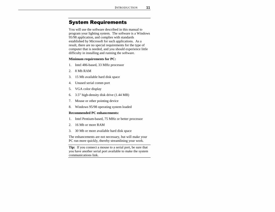
You will use the software described in this manual toprogram your lighting system. The software is a Windows95/98 application, and complies with standardsestablished by Microsoft for such applications. As aresult, there are no special requirements for the type ofcomputer that is needed, and you should experience littledifficulty in installing and running the software.
Minimum requirements for PC:
1. Intel 486-based, 33 MHz processor
2. 8 Mb RAM
3. 15 Mb available hard disk space
4. Unused serial comm port
5. VGA color display
6. 3.5” high-density disk drive (1.44 MB)
7. Mouse or other pointing device
8. Windows 95/98 operating system loaded
Recommended PC enhancements:
1. Intel Pentium-based, 75 MHz or better processor
2. 16 Mb or more RAM
3. 30 Mb or more available hard disk space
The enhancements are not necessary, but will make yourPC run more quickly, thereby streamlining your work.
Tip: If you connect a mouse to a serial port, be sure thatyou have another serial port available to make the systemcommunications link.
12 ETC COMPOSER PC SOFTWARE USER’S GUIDE
6RIWZDUH�,QVWDOODWLRQ
To install Composer software:
1. Make sure PC is turned on and Windows 95/98 isrunning.
2. Close all applications.
3. Locate sealed plastic bag containing distributiondiskettes.
4. If you have not already done so, read licenseagreement at front of this manual. If you agree toagreement terms, tear open plastic bag and removedistribution diskettes.
5. Insert diskette labeled Disk 1 into 3.5” floppy diskdrive on your PC. This drive is usually drive A:.
Note: If your floppy drive is not drive A:, substitute yourdrive name for A: in command.
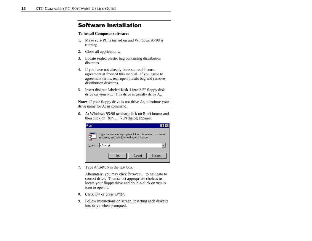
6. At Windows 95/98 taskbar, click on Start button andthen click on Run… Run dialog appears.
7. Type a:\Setup in the text box.
Alternately, you may click Browse… to navigate tocorrect drive. Then select appropriate choices tolocate your floppy drive and double-click on setupicon to open it.
8. Click OK or press Enter.
9. Follow instructions on screen, inserting each disketteinto drive when prompted.

INTRODUCTION 13
3&�&RQQHFWLRQYou must physically connect your PC communication(comm) port to the lighting system before you can controlyour lighting system. The connection is via a ReceptacleStation or directly to the MCP. Refer to the ComposerControl System Owner’s Manual (ETC part numberOMC) for details on the physical connections for theReceptacle Station.
6\VWHP�&RQQHFWLRQ
If you have luminaires in multiple rooms, you willprobably have a Receptacle Station for the PC-to-MCPconnection in each location to aid in programming. Thestation should be mounted in a convenient location so thatyou can use your PC freely. The receptacle is a standardfemale DB9 connector, allowing you to make a directconnection to the MCP using a standard DB9 serialextension cable. You can, though, connect directly to theMCP using the PC CONNECT connector.
To connect to Receptacle Station:
1. Place your computer in convenient location andconnect one end of DB9 serial extension cable (notsupplied) to serial port of your PC.
2. Connect other end of DB9 serial extension cable toReceptacle Station. Note that connector requiresspecific orientation.
Note: You must use a serial cable that has all pinsconnected straight through.
To connect to MCP:
1. Place your PC near MCP and connect one end ofDB9 serial extension cable (not supplied) to serialport of your PC.
2. Connect other end of cable to MCP connector labeledPC CONNECT.

14 ETC COMPOSER PC SOFTWARE USER’S GUIDE
(This page intentionally blank)

15
&KDSWHU���
*HWWLQJ�6WDUWHG
6WDUWLQJ�&RPSRVHU�6RIWZDUHBefore you begin programming your lighting system, youshould ensure that your luminaires are installed, allcabling is run and tested, the MCP and remote controlstations (if applicable) are mounted and connected, and alladdress settings are known. Refer to the installationinstructions and owner’s manuals for additionalinformation.
)URP�:LQGRZV�������6WDUW
0HQX
1. At Windows 95/98 taskbar, click Start button.
2. Click on Programs.
3. Click on Composer.
)URP�6KRUWFXW�RQ�'HVNWRS
1. At desktop Composer shortcut icon double-click leftmouse button.

16 ETC COMPOSER PC SOFTWARE USER’S GUIDE
&RQILJXULQJ�<RXU�6\VWHP
6HWWLQJ�&RPP�3RUW
If the software does not respond, access thecommunications setting dialog from the System menu.
To set or change comm port:
1. Make sure Composer application is running.
2. From System menu, choose Select CommPort…Communication dialog appears.
3. At Select Port for Composer communication. field,click radio button associated with comm port youwant to use.
4. In System type field, click radio button thatspecifies whether your system is PC Only or basedon MCP.
Note: PC only systems can be used for very small systems,temporary systems, and for demonstration purposes.
5. In Select Closest City field, click down arrow toopen selection window and select city closest to yourlocation to establish time zone information.
6. Click OK or press Enter.

CHAPTER 1. GETTING STARTED 17
6\VWHP�7HVW
Use system test to test your system to ensure that thecommunications link is valid. The test also validates theinstallation and proper operation of the luminaires and theentire control system.
While the test is active, all luminaires move through apredefined series of actions that exercise every fixtureparameter. Make note of any fixtures that are notbehaving correctly.
While the test is active, the LEDs on all remote controlstations will blink in a regular pattern. Check each stationto ensure that the communications link is good.
To enable system test:
1. Make sure Composer application is running.
2. From System menu, choose System Test. Checkmark indicates system test is active.
To disable system test:
1. From System menu, choose System Test. Checkmark disappears, indicating system test is disabled.
&UHDWLQJ�$�1HZ�3URMHFWBefore you can work with your automated lighting system,you must create a project and configure it by telling thesystem which hardware you are using within that project.Once a project has been created, rooms are opened andconfigured luminaires assigned to them. Rooms aresimply designations to divide luminaires into manageableareas, such as Dining Room and Lobby, or DisplayWindow One and Display Window Two.
Configuration information includes the name, address, anddevice type for both luminaires and remote controlstations.
The Lighting system can be configured by either use ofthe Auto Configuration feature or by opening a projectand configuring items individually.
Tip: System test willcontinue to run until disabled.

18 ETC COMPOSER PC SOFTWARE USER’S GUIDE
$XWR�&RQILJXUDWLRQ
The Auto Configuration feature creates files of allconfigurable items (luminaires and remotes) by polling thecommunication lines to see what equipment is installed.
To enable auto configuration:
1. Start Composer application.
2. From System menu, choose Auto Configuration.
3. Enter name for configuration file (or project) oraccept default.
4. Click Save or press Enter to save file. Autoconfiguration dialog box appears. Click Start.
5. When Configuration Data message reads:Completed Auto Configuration Successfully,Click OK.
CHAPTER 1. GETTING STARTED 19
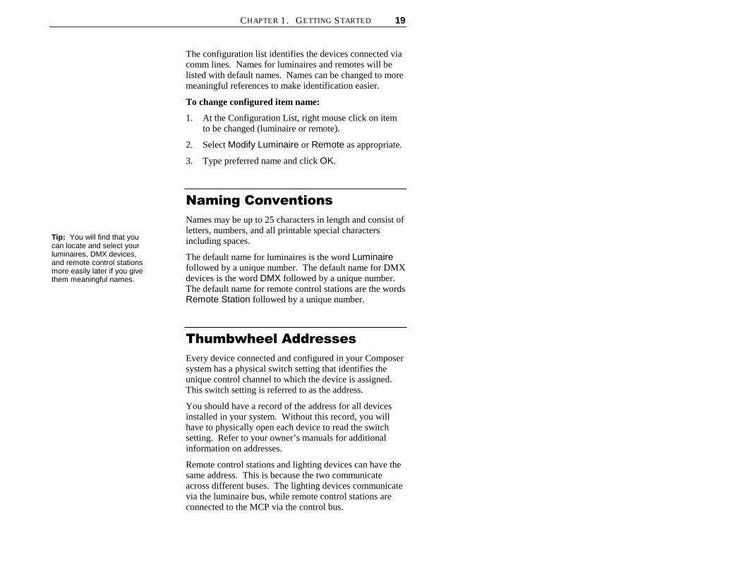
The configuration list identifies the devices connected viacomm lines. Names for luminaires and remotes will belisted with default names. Names can be changed to moremeaningful references to make identification easier.
To change configured item name:
1. At the Configuration List, right mouse click on itemto be changed (luminaire or remote).
2. Select Modify Luminaire or Remote as appropriate.
3. Type preferred name and click OK.
1DPLQJ�&RQYHQWLRQV
Names may be up to 25 characters in length and consist ofletters, numbers, and all printable special charactersincluding spaces.
The default name for luminaires is the word Luminairefollowed by a unique number. The default name for DMXdevices is the word DMX followed by a unique number.The default name for remote control stations are the wordsRemote Station followed by a unique number.
7KXPEZKHHO�$GGUHVVHV
Every device connected and configured in your Composersystem has a physical switch setting that identifies theunique control channel to which the device is assigned.This switch setting is referred to as the address.
You should have a record of the address for all devicesinstalled in your system. Without this record, you willhave to physically open each device to read the switchsetting. Refer to your owner’s manuals for additionalinformation on addresses.
Remote control stations and lighting devices can have thesame address. This is because the two communicateacross different buses. The lighting devices communicatevia the luminaire bus, while remote control stations areconnected to the MCP via the control bus.
Tip: You will find that youcan locate and select yourluminaires, DMX devices,and remote control stationsmore easily later if you givethem meaningful names.
20 ETC COMPOSER PC SOFTWARE USER’S GUIDE
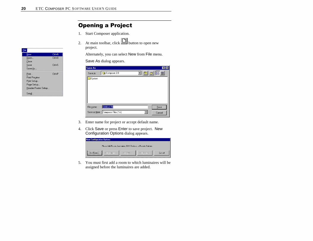
2SHQLQJ�D�3URMHFW
1. Start Composer application.
2. At main toolbar, click button to open newproject.
Alternately, you can select New from File menu.
Save As dialog appears.
3. Enter name for project or accept default name.
4. Click Save or press Enter to save project. NewConfiguration Options dialog appears.
5. You must first add a room to which luminaires will beassigned before the luminaires are added.

CHAPTER 1. GETTING STARTED 21
$GGLQJ�/XPLQDLUHV
1. At New Configuration Options dialog, click on AddLuminaires… Luminaire Configuration dialogappears.
2. At Name: field, enter name for luminaire or acceptdefault name.
3. At Address: field, enter address assigned toluminaire or accept default address. Address mustmatch address entered onto thumbwheel addressswitch on luminaire.
4. At Bus: field, enter bus device is connected to oraccept default bus.
5. At Room Assigned: field, select room assignmentfrom previously created room(s).
6. At Model field, click on radio button for luminairebeing added.
7. At Options field, click on options contained inluminaire being added. Options vary based onluminaire model selected.
8. Click Add button to add luminaire configuration tosystem and to reset Luminaire Configuration dialogto allow for more luminaires to be added.
9. When all luminaires are added, click Done to returnto New Configuration Options dialog.
10. Click Done if no remotes or DMX devices are to beadded.

22 ETC COMPOSER PC SOFTWARE USER’S GUIDE
$GGLQJ�'0;�'HYLFHV
If using DMX devices instead of, or in addition to ETCluminaires, the DMX devices will have to be added. Theprocess is similar to adding luminaires.
1. At New Configuration Options dialog, click on AddDMXs… DMX Configuration dialog appears.
2. At Name: field, enter name for DMX device oraccept default name.
3. At Address: field, enter address assigned to DMXdevice or accept default address. Address mustmatch address entered on DMX device.
4. At Room Assigned: field, select room assignmentfrom previously created room(s).
5. Click Add button to add DMX device configurationto system and to reset DMX Configuration dialog toallow for more devices to be added.
6. When all DMX devices are added, click Done toreturn to New Configuration Options dialog.
7. At New Configuration Options dialog, click onDone to return to main Composer screen.
$GGLQJ�5HPRWH�&RQWURO
6WDWLRQV
If using Remote Control stations, the stations will have tobe added. The process is similar to adding luminaires.
The lighting actions caused by remote control stationevents are specified by data in a template. You maychange templates from one day and time to the next byscheduling template assignments.
CHAPTER 1. GETTING STARTED 23
Until a given template is explicitly assigned to a remotecontrol station, the Composer system relies on a defaulttemplate to specify station behavior. You may change thedefault template at any time from the Remote ControlStation Configuration dialog.
Note: If you do not specify a default template, theComposer system will display [No Template] as thedefault template. You will have to manually assign adefault template.
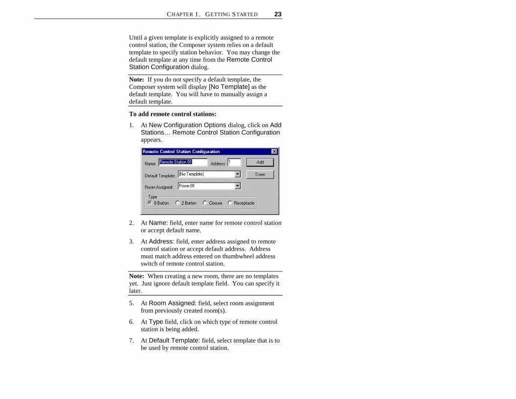
To add remote control stations:
1. At New Configuration Options dialog, click on AddStations… Remote Control Station Configurationappears.
2. At Name: field, enter name for remote control stationor accept default name.
3. At Address: field, enter address assigned to remotecontrol station or accept default address. Addressmust match address entered on thumbwheel addressswitch of remote control station.
Note: When creating a new room, there are no templatesyet. Just ignore default template field. You can specify itlater.
5. At Room Assigned: field, select room assignmentfrom previously created room(s).
6. At Type field, click on which type of remote controlstation is being added.
7. At Default Template: field, select template that is tobe used by remote control station.

24 ETC COMPOSER PC SOFTWARE USER’S GUIDE
8. Click Add button to add remote control stationconfiguration to system and to reset Remote ControlStation Configuration dialog to allow more stationsto be added.
9. When all remote control stations are added, clickDone to return to New Configuration Optionsdialog.
10. At New Configuration Options dialog, click Doneto return to main Composer screen.
0RGLI\LQJ�/XPLQDLUH��'0;
'HYLFH��RU�5HPRWH�&RQWURO
6WDWLRQ�&RQILJXUDWLRQ�'DWD
The process to modify your configuration data forluminaires, DMX devices, and remote control stations isessentially the same.
1. At View menu, choose Configuration List. A list ofconfigured items appears at bottom of screen.
2. Place cursor over item to be modified and click rightmouse button. Select Modify Luminaire, ModifyDMX Device, or Modify Remote Station.

CHAPTER 1. GETTING STARTED 25
Alternately, from System Menu, select Configureand then item to be modified.
3. Change configuration data as necessary.
4. Click OK or press Enter key when done.
5HPRYLQJ�/XPLQDLUH��'0;
'HYLFH��RU�5HPRWH�&RQWURO
6WDWLRQ�)URP�D�5RRP
To remove or unassign the device you have to be able toview the device name from the configuration list (to selectit).
1. At Configuration list, right mouse click on device tobe removed or unassigned from room.

26 ETC COMPOSER PC SOFTWARE USER’S GUIDE
Removing (or unassigning) an item from a roomallows the item to remain in the system configurationfor use in another room Deleting an item from theconfiguration table will remove it from the systemcompletely.
'HOHWLQJ�/XPLQDLUH��'0;
'HYLFH��RU�5HPRWH�&RQWURO
6WDWLRQ�)URP�&RQILJXUDWLRQ
'DWD
To delete the device you have to be able to view thedevice name from the configuration list (to select it).
Deleting an item from the Configuration List removes it,and its associated data, entirely from the system. Onceremoved from the Configuration List, the item will need tobe added back before it can be re-assigned for use byanother room.
1. At Configuration List, right mouse click on device tobe deleted from project.

CHAPTER 1. GETTING STARTED 27
2. At menu, click on either Delete Luminaire, DeleteDMX Device, or Delete Remote Station. Deletionwarning dialog appears.

28 ETC COMPOSER PC SOFTWARE USER’S GUIDE
2SHQLQJ�([LVWLQJ�3URMHFWA project is considered existing if you have opened a fileand assigned a name to it -- even if you did not add anyluminaires or remote control stations.
1. Start Composer application.
2. At main toolbar, click button to open existingproject.
Alternately, you can select Open from File menu.
Open dialog appears.
3. Navigate to directory where project is stored.
4. Click on name of project to be opened and then clickon Open.
Alternately, double-click on project name to open.
Tip: You can open anexisting project by selectingproject name from File menunumbered recently used list.

CHAPTER 1. GETTING STARTED 29
$GGLQJ�5RRPVWhen the system is initially configured, a room wascreated into which all luminaires and remote stations wereassigned. It may be desirable to add additional rooms anddivide the luminaires and remotes for better managementof lighting assets.
&UHDWLQJ�$GGLWLRQDO�5RRPV
1. At main toolbar, click to add a new room.
2. Name room or accept default. When all desiredrooms have been added, select Done.

30 ETC COMPOSER PC SOFTWARE USER’S GUIDE
$GGLQJ�/XPLQDLUHV��'0;
'HYLFHV��RU�5HPRWH�&RQWURO
6WDWLRQV�WR�([LVWLQJ�3URMHFW
You can add luminaires, DMX devices, and remotecontrol stations to existing projects several ways using theconfiguration dialogs. You modify or delete devices asmentioned above.
1. Make sure desired project is open.
2. Make sure configuration list is open. At View menu,choose Configuration List.
3. At System menu, choose Configure.
4. Click on either Add Luminaire, Add DMX Device,or Add Remote Stations. Configuration dialogappears.
5. Enter new device configuration data as necessary.

CHAPTER 1. GETTING STARTED 31
6. Click Add button to add configuration data to systemand to reset configuration dialog to allow for moredevices to be added.
7. When all devices are added, click Done to return tomain Composer screen.
8. Repeat Steps 3 through 6 for other types of devices.
$VVLJQLQJ�/XPLQDLUH��'0;
'HYLFH��RU�5HPRWH�&RQWURO
6WDWLRQ�WR�1HZ�5RRPV�
1. At Configuration List, right mouse click on the itemto be added.
2. Select Assign To and the Room to which the item isbeing added. A luminaire, DMX Device, or RemoteControl Station can be assigned to only one room at atime.

32 ETC COMPOSER PC SOFTWARE USER’S GUIDE
*HWWLQJ�)DPLOLDU�ZLWK�&RPSRVHU
6RIWZDUH
0DLQ�7RROEDU
New buttonUse this button to open a new room file.
Open buttonUse this button to open an existing room file.
Select Room MenuUse this drop-down menu to select rooms.
Add Room buttonUse this button to create a new room.
Delete Room buttonUse this button to delete a room.
Preset Tools buttonUse this button to open the preset tools screen.This screen contains all of the tools needed tomanipulate your lighting system and to store,edit, and delete presets.
Sequence Tools buttonUse this button to open the sequence toolsscreen. This screen contains all of the toolsneeded to store, edit, and delete sequences.
Event Tools buttonUse this button to open the event tools screen.This screen contains all of the tools needed tostore, edit, and delete events.
CHAPTER 1. GETTING STARTED 33
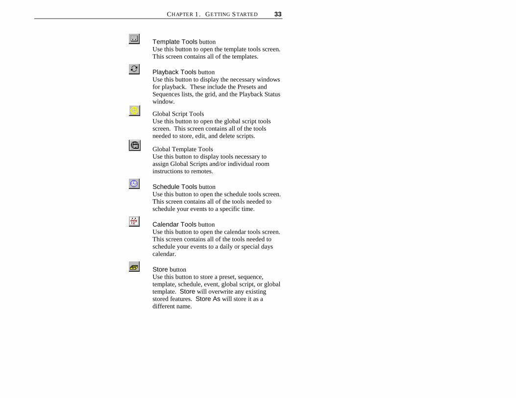
Template Tools buttonUse this button to open the template tools screen.This screen contains all of the templates.
Playback Tools buttonUse this button to display the necessary windowsfor playback. These include the Presets andSequences lists, the grid, and the Playback Statuswindow.
Global Script ToolsUse this button to open the global script toolsscreen. This screen contains all of the toolsneeded to store, edit, and delete scripts.
Global Template ToolsUse this button to display tools necessary toassign Global Scripts and/or individual roominstructions to remotes.
Schedule Tools buttonUse this button to open the schedule tools screen.This screen contains all of the tools needed toschedule your events to a specific time.
Calendar Tools buttonUse this button to open the calendar tools screen.This screen contains all of the tools needed toschedule your events to a daily or special dayscalendar.
Store buttonUse this button to store a preset, sequence,template, schedule, event, global script, or globaltemplate. Store will overwrite any existingstored features. Store As will store it as adifferent name.
34 ETC COMPOSER PC SOFTWARE USER’S GUIDE
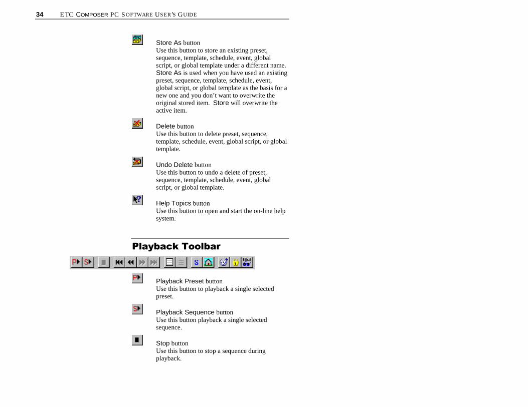
Store As buttonUse this button to store an existing preset,sequence, template, schedule, event, globalscript, or global template under a different name.Store As is used when you have used an existingpreset, sequence, template, schedule, event,global script, or global template as the basis for anew one and you don’t want to overwrite theoriginal stored item. Store will overwrite theactive item.
Delete buttonUse this button to delete preset, sequence,template, schedule, event, global script, or globaltemplate.
Undo Delete buttonUse this button to undo a delete of preset,sequence, template, schedule, event, globalscript, or global template.
Help Topics buttonUse this button to open and start the on-line helpsystem.
3OD\EDFN�7RROEDU
Playback Preset buttonUse this button to playback a single selectedpreset.
Playback Sequence buttonUse this button playback a single selectedsequence.
Stop buttonUse this button to stop a sequence duringplayback.

CHAPTER 1. GETTING STARTED 35
Go To First Item buttonUse this button to go to the first preset in aselected sequence.
Step Back buttonUse this button to step back through the presetsof a selected sequence.
Step Forward buttonUse this button to step forward through thepresets of a selected sequence.
Go To Last Item buttonUse this button to go to the last preset of aselected sequence.
Select All buttonUse this button to select all items.
Deselect All buttonUse this button to deselect all items.
Synchronize buttonUse this button to synchronize all selectedfixtures. This will allow you to bring luminairesthat are not moving in time identically to asynchronized form.
Send Home buttonUse this button to send all selected devices totheir Home position. The Home position is apreset that you can create that allows you toprogram a preset with your lighting devicesstarting from a known position. In addition, thisis the position luminaires will go to after a hardreset or after calibration.
Activate Timing buttonUse this button to either activate or turn offtiming when playing back presets and sequences.This will allow you to view a preset or sequencethat may have a long timing value without havingto wait for the time to elapse.

36 ETC COMPOSER PC SOFTWARE USER’S GUIDE
Lockout buttonUse this button to lock out a system from anyintrusion.
Blind buttonUse this button to use the Composer software inblind mode. Blind mode allows you to programyour system without having the luminairesactually move.
(GLWRU�7RROEDU
Remove Item buttonUse this button to remove an item from an activeeditor list; for instance, a preset from thesequence main body.
Clear buttonUse this button to clear all of the contents of awindow, for instance all of the contents of theSequence Main Body.
Add Global ScriptUse this button to add a Global Script to a listing.
Add Power Cmd buttonUse this button to add a power command to turna luminaire on or off.
Add Schedule Cmd buttonUse this button to add a schedule command.You can disable a schedule for a specifiedamount of time, disable a schedule, or enable aschedule that has been disabled.
CHAPTER 1. GETTING STARTED 37
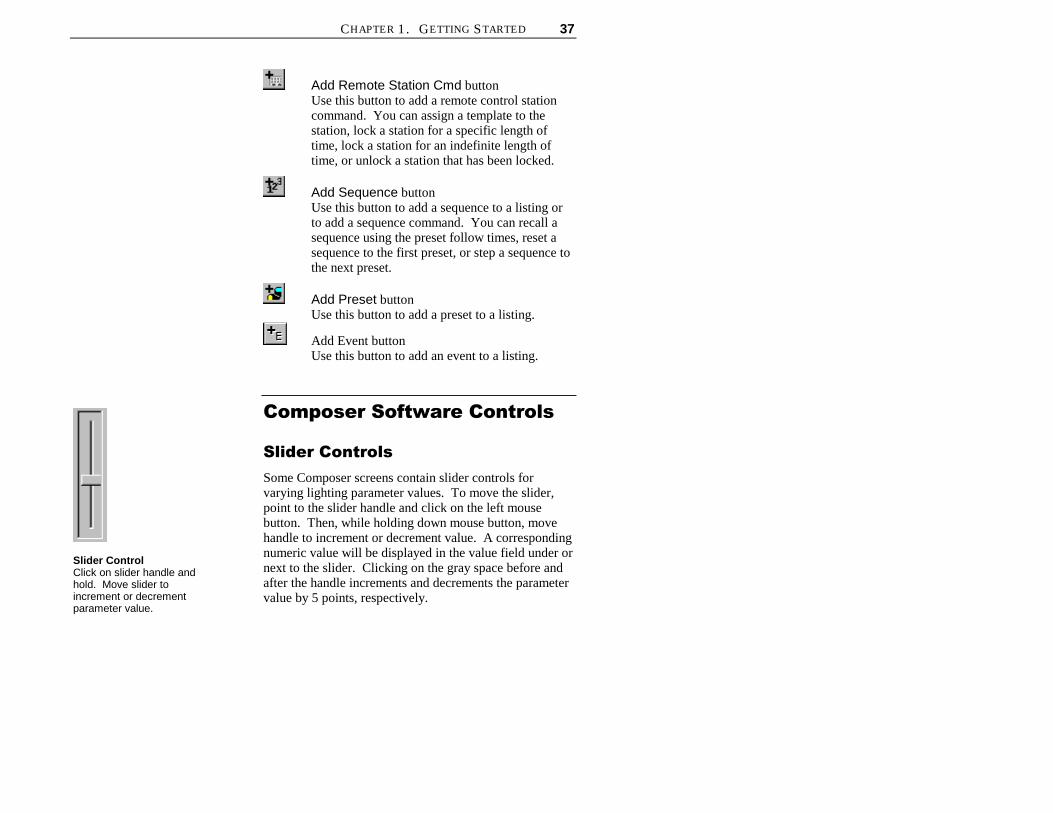
Add Remote Station Cmd buttonUse this button to add a remote control stationcommand. You can assign a template to thestation, lock a station for a specific length oftime, lock a station for an indefinite length oftime, or unlock a station that has been locked.
Add Sequence buttonUse this button to add a sequence to a listing orto add a sequence command. You can recall asequence using the preset follow times, reset asequence to the first preset, or step a sequence tothe next preset.
Add Preset buttonUse this button to add a preset to a listing.
Add Event buttonUse this button to add an event to a listing.
&RPSRVHU�6RIWZDUH�&RQWUROV
6OLGHU�&RQWUROV
Some Composer screens contain slider controls forvarying lighting parameter values. To move the slider,point to the slider handle and click on the left mousebutton. Then, while holding down mouse button, movehandle to increment or decrement value. A correspondingnumeric value will be displayed in the value field under ornext to the slider. Clicking on the gray space before andafter the handle increments and decrements the parametervalue by 5 points, respectively.
Slider ControlClick on slider handle andhold. Move slider toincrement or decrementparameter value.

38 ETC COMPOSER PC SOFTWARE USER’S GUIDE
'LUHFW�(QWU\
Some Composer screens allow you to directly enter aparameter value in the value field under or next to a slidercontrol. Just click in the value field and type in thedesired value. Then click outside the field, or press theTab key to exit the field and affect the change.
&URVVKDLUV�&RQWURO
The pan and tilt values can be roughly approximated usingthe crosshairs control on the preset tools screen. Thecrosshairs show on an X-Y axis, the rough position of theluminaires. The axis does not truly represent up and downor left and right, and should therefore, be used to roughlyposition your lighting devices.
Use the crosshairs by pointing at the plus-sign-shapedcrosshairs (+) and clicking the left mouse button. Then,while holding down mouse button, move crosshairs toroughly position lighting devices.
Make fine adjustments to the pan and tilt positions usingthe pan and tilt sliders or direct entry fields.
,QFUHPHQW�'HFUHPHQW�%XWWRQV
Several Composer screens use increment and decrementbuttons to make parameter changes, especially for timingvalues. For timing values, use the buttons by clicking oneither the minutes or seconds and then clicking on the topor bottom button to increment or decrement the timingvalue. If you do not click on the minutes or seconds, thesystem default is to change the minutes first. For otherfields using increment/decrement buttons, click on the topor bottom button to increment or decrement the value.
Alternately, you can click on the minutes or secondsvalues and use the up and down keyboard cursorpositioning keys to increment or decrement the timingvalue. Press the Tab key to move through timing valuefields.
Lastly, you can click on the minutes and seconds valuesand directly enter a value from the keyboard to assigntiming values.
Increment/DecrementButtonsClick on minutes or secondsand then click on buttons toright to increment ordecrement timing values.
Crosshairs ControlClick on crosshairs and holdand move to roughlypositions lighting devices.
Parameter Value FieldClick in field and enternumeric value. Then clickoutside field or press Tab keyto affect change
Delay Timing Check BoxesClick on box or I, F, C, Bletters to enter check in box

CHAPTER 1. GETTING STARTED 39
'HOD\�7LPLQJ�&KHFN�%R[HV
The Delay timing check boxes are used to assign delaytiming to particular parameters. The entered delay timewill only be assigned to those parameters for which thecheck box is checked. Click on the box or I, F, C, Bletters to enter a check in the box or remove a check.
6HOHFWLQJ�,WHPV�)URP�/LVWV
To select group of contiguous (adjacent) items:
1. At list window, click on item to be selected.
2. While holding keyboard Shift key, using left mousebutton, click on last item. All contiguous items fromthe first- to the last-selected are highlighted.
3. Release Shift key and click again to deselect group.
To select group of discontiguous items (items that arenot adjacent):
1. At list window, click on item to be selected.
2. While holding keyboard Ctrl key, using left mousebutton, select another item. Both items are selected.
3. Continue to hold Ctrl key and click on items to beselected. Each selected item is highlighted.
4. Hold Ctrl key and click on highlighted selected itemsto deselect them.
5. Release Ctrl key and click again to deselect entiregroup.
Contiguous list items.
Discontiguous list items.

40 ETC COMPOSER PC SOFTWARE USER’S GUIDE
0RXVH�3RSXS�0HQXV
Several Composer screens contain windows that havemouse popup menu choices available. For those windowsthat have the popup menu available, in all instances, tobring up the popup menu, you need to click on the rightmouse button with the cursor pointing in the window. Forinstance, to call up the popup menu for the Presets list,you must have your mouse pointing in the Presets list.For the Luminaires - Dmxs list, you must have yourmouse pointing in the Luminaires - Dmxs list.
The popup menu choices are all also available through themain toolbar, playback toolbar, or main screen drop downmenus.
*ULG�'HVFULSWLRQ
The grid is a spreadsheet-like representation of the dataassigned to your configured lighting system components.Each column represents the data that were entered duringthe configuration of your system. In addition, manualcontrol data is also displayed. The manual controls datacan be edited from the grid by clicking on the box. Youcan then enter a numerical value in the box to edit thefield. You can also check the delay timing parametercomponents located at the far right.
When you change your page setup configuration forprinting, the grid will display the changes when you selectPrint Preview from the File menu. There are also griddisplay buttons available during print preview.
CHAPTER 1. GETTING STARTED 41
6FUHHQ�3ODFHPHQW�DQG�6L]LQJ
When you start the Composer software, you will be ableto open several different tools screens. These screenshave smaller separate windows that open when you startthe tools. You can selectively open and close any of thewindows by selecting the windows from the View menu.Items that you want to view will have a check mark nextto them.
You may size the windows as desired using the split barsthat separate the windows. In addition, if you double-click on the gray space inside the window, the list willbecome a free-floating window, allowing you to place thewindow wherever you wish. Double-click on the title bara second time to replace the window to its defaultposition. By modifying the size of the windows, as manyeditors and windows can be opened at the same time asneeded. Note that the more windows that are open, thesmaller each window can be for all to still fit on yourmonitor screen.
6\VWHP�/LPLWV�DQG�%RXQGDULHV
The range of allowable settings is typically limited to therange 0 to 1,000.
The following elements are limited to 1,000:
• Maximum number of presets per room.
• Maximum number of sequences per room.
• Maximum number of templates (per template type).
• Maximum number of event lists per room (with eachlist containing a maximum of 1000 actions).
The maximum number of schedules is limited to 254.
The maximum number of actions (preset, sequence,event,etc.) per schedule is 255.

42 ETC COMPOSER PC SOFTWARE USER’S GUIDE
(This page intentionally blank)

43
&KDSWHU���
3UHVHWV
A preset is a user-defined lighting look that specifies allcontrollable parameters for each device in your system.You will use the Composer preset tools to define thispreset look. The act of defining a look is referred to asprogramming the preset.
In general, a preset consists of lighting, timing and delaytime parameters. When creating presets containing DMXdevices, the intensity controller is used for setting onlyparameter data, based on the selected channel.
When creating presets containing DMX devices, theintensity controller is used for setting all parameter data,based on the selected channel.
3UHVHW�7RROVThe preset tools are the tools that you use to create andedit presets. The tools are available from the toolbar andfrom the drop-down menus.
You must have your project file open and configuredbefore you can work with presets. The file contains yoursystem configuration, including the types and addresses ofyour luminaires, and so it is required for the system tocommunicate with the lighting devices.
Preset tools button on maintoolbar.

44 ETC COMPOSER PC SOFTWARE USER’S GUIDE
6WDUWLQJ�3UHVHW�7RROV
1. Make sure that Composer application is running andyour lighting project file is open. Ensure desiredroom is selected.
2. At main toolbar click button. Preset tools screenappears.
Alternately, from Program menu, choose Presets.
*HWWLQJ�)DPLOLDU�ZLWK�3UHVHW
7RROV�6FUHHQ
The preset tools contains several windows that open bydefault to allow for manual control of your luminaires:
• Main toolbar
• Presets list
• Timing fields
• Playback toolbar
• Color palette
• Absolute controls
• Relative controls
• Luminaires - Dmxs list
• DMX Devices list.

45
Playback Toolbar Main Toolbar Timing Fields Color Palette
Presets List luminaire/DMX List Focus Points Group Selects Absolute Controls
Active Preset

46 ETC COMPOSER PC SOFTWARE USER’S GUIDE
3UHVHWV�/LVW
A preset is a user-defined lighting look that specifies allcontrollable parameters for each device in your system.You will assign values to each luminaire parameter tocreate the lighting look you desire. The names of allstored presets appear in the Presets list. As you createnew presets you will name them, accumulating a growinglist of presets, all displayed in the Presets list. Once youhave more presets than will fit in the window, a scroll barautomatically appears.
Note: To select another preset, double click on the desired preset.The name of the active preset is displayed at the bottom of thescreen.
/XPLQDLUHV���'P[V�/LVW
As you assign luminaires and DMX devices in your roomfile, they will be available from the Luminaires - Dmxslist window. Only the names of rooms assignedluminaires and DMX devices appear in the list.
*URXS�6HOHFWV
Group Selects are user defined groupings of luminaires.This feature allows the user to select a pre-defined list ofluminaires. For example: If a grid layout of 36luminaires were arranged as six rows of six luminaireseach, separate group selects might be established for eachrow and for each column of luminaires. These 12 groupselects would allow the user to select all luminaires withina single row or column with a single mouse click and thenchange their color or position simultaneously. A total of36 defined group selects may be saved and stored inmemory for each room.
)RFXV�3RLQWV
Focus Points are user defined positions that specificluminaires have been focused as starting points fromwhich presets may be defined. Preset positions may bebased on these focus points. If a focus point is changed,all presets based on that focus point will also change. As
Presets list window containsnames of all stored presets.
Luminaires - Dmxs listwindow contains names andconfiguration data for allluminaires.

CHAPTER 2 PRESETS 47
an example: A number of presets have been defined tohighlight a display, based on a focus point. The decisionis then made to re-position the display. All previouslydefined presets can be shifted to the new display locationby simply redefining the focus point on which the presetswere based. A total of 36 defined focus points may besaved and stored in memory for each room.
$EVROXWH�&RQWUROV�5HODWLYH�&RQWUROV
When you program a preset, you first specify the intensity,focus (position), color, and beam setting for each devicein your system. You access the preset tools to makechanges to these parameters.
These settings together constitute the appearance of yourlighting after all of the devices have adopted theirprogrammed positions. Since the devices must passthrough a transition to arrive at this look, the final lightingappearance is called the target state of the preset.
There are two types of controls to set in the parameters:absolute and relative controls. Absolute controls are thedefault controls displayed. Relative controls can bedisplayed by selecting Relative Controls from theControl menu.
Absolute ControlsRelative Controls
The main difference between these controls is thatabsolute controls will change all selected device

48 ETC COMPOSER PC SOFTWARE USER’S GUIDE
parameters to the same value, while relative controlsincrement each parameter value by the same value.
As an example, say two luminaires have tilt values of 200and 300 respectively. Using the absolute controls, if youselect the two luminaires and change the tilt value to 350,both luminaires will now show the tilt setting at 350. Ifyou were using the relative controls and increment the tiltvalue by 50, the luminaires would have tilt values of 250and 350.
Intensity
The intensity parameter specifies the brightness of thelight emerging from luminaires. An opaque mechanismwithin the instrument is used to interfere with the lightbeam. When open (full intensity), the mechanism doesnot interfere with the beam. When closed (zero intensity),the mechanism fully interferes with the beam, completelyblocking the light.
Intensity can be specified in percent or absolute values.As a percentage, 100 steps are provided from zero to fullintensity. For absolute values, the intensity motor has 256steps, allowing smoother fades.
DMX device values are set using the intensity control.
Focus
The focus of a luminaire is determined by its pan and tiltpositions. For ETC luminaires with moving heads onestepper motor pans the fixture in a circular direction aboutthe base, moving the head horizontally through a 360°range. A second motor tilts the fixture around a pivotpoint centered in the yoke, moving the head verticallythrough a specific range determined by the type ofluminaire in use. For ETC recessed luminaires, a movingmirror reflects the light beam along an X and Y axisperforming the pan and tilt functions.
Focus is specified as a numeric value between zero and1023 for each of the pan and tilt parameters Although themotors themselves provide somewhat fewer physicalpositions, this represents a logical range of 1024 steppedpositions, providing control that is both smooth andprecise.
CHAPTER 2 PRESETS 49
Color
Color is specified by the luminaire’s color parameter.Some luminaires contain fixed color filters that areintroduced into the light beam to change color. Otherluminaires rotate color filters into the light beam. In itsopen position, the color mechanism passes allwavelengths (white light).
For the three-color filter color mechanisms, the blue,amber, and magenta filters appear in series, each affectingthe beam as it is passed from the previous filter in theseries. The combined result of the three stages producesthe final color mix.
Each color motor has 256 stepped positions, providingmillions of possible color settings. Color is specified asthree numeric values, each between zero and 255. Thereis one value for each of the three color filters.
For luminaires utilizing fixed color filters, a color wheelcontaining eight discreet filters and one open position isused. Two standard color wheels are available: onesaturated color wheel and one pastel color wheel.
Beam
Only luminaires that are equipped with a diffusionmechanism support beam control. The beam parameterspecifies the size and sharpness of the beam emergingfrom such luminaires. A motor passes diffusing panelsinto the light beam. When open (normal wash), the panelsdo not interfere with the light path, providing a collimatedbeam. When fully closed (maximum diffusion), theblades fully interfere with the light path, providing thewidest beam angle allowed by the lens.
Beam is specified as a percentage, providing 100individual steps from zero to full diffusion. The beammotor has 256 stepped positions, allowing smoothtransitions with imperceptible stepping.

50 ETC COMPOSER PC SOFTWARE USER’S GUIDE
7UDQVLWLRQ�7LPH�3DUDPHWHUV
After specifying the target state, program the timingparameters, values that control the transitions betweenlooks, to finish programming a preset. The transition timeis the specified time during which each device movesfrom its current state to its target state.
Presets include a separate transition time for each lightingparameter of the luminaire. The value represents theamount of time that the luminaire will take to change agiven parameter from its current position to the newposition specified by the preset. Since it may be in anyposition when instructed to go recall a preset, theluminaire itself calculates the motor speeds required tomove each parameter from its current to its target state.
There can be a separate transition time for intensity, focus,color, and beam.
'HOD\�7LPH�3DUDPHWHUV
In addition to the transition time, you can specify a delaytime to specific luminaires. The delay time is a waitingtime that allows lighting parameters to start their transitionlater than others.
The delay timer begins when a triggering action firstrecalls the preset. After the delay time has passed, thoseparameters marked for delay begin their transitions. Youenter a delay duration in a data field and then click inparameter check boxes to select the parameters to bedelayed. Any combination of intensity , focus, color, andbeam can be marked for delay.
CHAPTER 2 PRESETS 51
/LYH�DQG�%OLQG�3URJUDPPLQJ
There are two modes used for programming: live andblind. When you are programming in live mode, you havedirect, real-time access to your lighting system. Yourfeedback is the behavior of the luminaires themselves.Blind mode is used when you cannot be in the space toobserve your lighting changes. You may specify alllighting parameters off-line and then later, fine-tune yourpresets during a live mode programming session.
When you start the preset tools, the system willautomatically default to live mode. To enter blind mode,
click on button or select Blind Mode from Systemmenu.
Although it may seem at first that there is little that youcan do without direct access to the lighting system, youwill find that much of your work can actually beaccomplished quickly through programming in blindmode. For example, you could configure your system andcreate a project file and create custom colors.
/LYH�0RGH�3URJUDPPLQJ�%HQHILWV
• You can manipulate intensity, focus, color, and beamparameters directly.
• You can store current, visible state of all luminairesas named preset.
• All operations are immediately reflected in behaviorof selected instruments.
• Luminaires in selected presets adopt preset targetstate.
• If preset time value has been entered, newly-selectedpresets move to their target state according tospecified transition time.
Reminder: Your computermust be connected to theMCP via a ReceptacleStation before you canprogram in live mode.

52 ETC COMPOSER PC SOFTWARE USER’S GUIDE
%OLQG�0RGH�3URJUDPPLQJ�%HQHILWV
• You need not be present at site to effect changes.
• You can perform certain repetitive tasks more quicklywithout distraction of lighting changes.
• You don’t interfere with normal use of site (forinstance meetings can go on) and remote stationscontinue to operate.
• You can create or edit sequence, schedules, orcalendars completely off-site.

CHAPTER 2 PRESETS 53
&UHDWLQJ�DQG�0DQDJLQJ�3UHVHWVThe names of your presets appear in the Presets listwindow. Parameter changes only apply to an activepreset. A preset is active if it is selected (highlighted)from the Presets list. You may highlight any preset bypointing at the preset name and clicking. You canplayback the preset by double-clicking on the name. Ifyou click the right mouse button while pointing in thePresets window, you can playback, store, or deletepresets.
As you program your lighting looks into the system, youmay find it convenient to create a preset from theluminaire’s previous position (previous preset), a Homepreset, or a Focus Point.
+RPH�3UHVHW
You may want to start programming your system from aknown state. This state can be the default Home positionpreprogrammed into your ETC luminaire or a personally-designed default Home state that you can store as theHome preset. The Home preset is available on the
playback toolbar through the button.
For ETC luminaires, the Home position is stored in theluminaire. It does not receive this preset data from thecontrol system. The Home preset is used as the presetthat the lighting devices will go to when they havefinished calibrating.
When you click on the button, the selected lightingdevices will go to the Home preset. Any timing valuesassigned to the preset will also be invoked.
To create Home preset:
1. Make sure that preset tools screen is started andplayback toolbar is displayed.
2. Manipulate manual controls to create Home preset.
Use button to sendlighting devices to knownHome position.

54 ETC COMPOSER PC SOFTWARE USER’S GUIDE
3. From Control menu, choose Default Presets.
4. Select Store Home. Preset is now assigned to button.
Alternatively, you can select Play Home fromControl menu Default Presets to send selectedlighting devices to Home preset values.
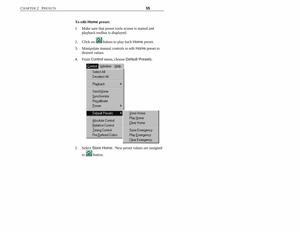
CHAPTER 2 PRESETS 55
To edit Home preset:
1. Make sure that preset tools screen is started andplayback toolbar is displayed.
2. Click on button to play back Home preset.
3. Manipulate manual controls to edit Home preset todesired values.
4. From Control menu, choose Default Presets.
5. Select Store Home. New preset values are assigned
to button.

56 ETC COMPOSER PC SOFTWARE USER’S GUIDE
To delete Home preset:
1. Make sure that preset tools screen is started andplayback toolbar is displayed.
2. From Control menu, choose Default Presets.
3. Select Clear Home. Home preset is cleared.
Clicking button will return to default parametersof full intensity, no color, and pan and tilt position of512.
Note: Once cleared, there is no undo feature for home presets.

CHAPTER 2 PRESETS 57
&UHDWLQJ�*URXS�6HOHFWV
1. Make sure that preset tools screen is started.
2. Select all luminaires to be controlled as a group. UseShift key for contiguous items in a list. Use Ctrl keyfor discontiguous items in a list.
3. Select an unused Group Select button (or a previouslyassigned button if you wish to over write it) and rightmouse click the button. At the sub menu, select NewGroup Select.
4. Enter name for Group Select or accept default name.Give Group Select unique name; you can not havetwo Group Selects that have same name.
5. Press Enter or click OK. Group Select is assigned tobutton.
Note: If Group Select is deleted, there is no undo feature.

58 ETC COMPOSER PC SOFTWARE USER’S GUIDE
&UHDWLQJ�)RFXV�3RLQWV
1. Make sure that preset tools screen is started.
2. Starting from a Home preset or any other preset,select luminaires and adjust pan and tilt parameters toachieve desired point of focus. Focus Points retainonly pan and tilt information, so it is not necessary toset other parameters.
3. Select an unused Focus Point button (or a previouslyassigned button if you wish to over write it) and rightmouse click the button. At the sub menu, select NewFocus Point or Update Focus Point, asappropriate. Update will overwrite previous setting.
4. Enter name for Focus Point or accept default name.Give Focus Point unique name; you can not have twoFocus Points that have same name.
5. Press Enter or click OK. Focus Point is assigned tobutton.
New presets may now be assigned based on this FocusPoint. When Focus Point is modified, all presets createdbased on that Focus Point will change.
Note: If Focus Point is deleted, there is no undo feature.

CHAPTER 2 PRESETS 59
/LJKWLQJ�3DUDPHWHUVYou will spend most of your time working directly withthe lighting parameters as you create and edit presets. Thepreset tools provide a unique tool for manipulating eachlighting parameter. The system default preference is toassign all parameter values based on 256-step values.You can change the setting on which to base yourintensity and beam parameters to 0 to 100 percent fromthe Preferences… selection from the System menu.
The following sections will assume the default 256-stepscale preference is selected.
6HWWLQJ�,QWHQVLW\
The preset tools Intensity manual control is used toexpress the brightness of the selected devices. Theintensity control is graduated into 256 discrete steps,where 0 is fully dimmed and 255 is brightest.
You may select channels individually to specify exactintensity relationships on a device-by-device basis. Youmay also select multiple channels, allowing you to adjustthe intensity of several devices simultaneously.
Note: Remember that when using absolute controls theparameter value displayed in the box corresponds to theselected lighting device. If more than one lighting deviceis selected, the data corresponds to the first selectedluminaire in the list. When using relative controls eachselected luminaire will be modified by same value.
Display intensity and beamvalues based on 0 - 100percent or 0 - 255 absolutevalues (for greater resolution).

60 ETC COMPOSER PC SOFTWARE USER’S GUIDE
Manipulate slider withmouse for continuouscontrol over intensity.
Type desired intensityvalue or view currentsetting in white text box.
To assign intensity value to lighting device:
1. From Luminaires - Dmxs list, select luminaires forwhich intensity is to be manipulated.
2. At Intensity manual control, set intensity to desiredvalue.
6SHFLI\LQJ�)RFXV
The preset tools represents focus as a pair of values, onefor the pan position and one for the tilt position. Eachmotor control is graduated into 1024 discrete steps, where0 is beginning of travel and 1023 is end of travel.
You will usually individually select lighting devices tospecify exact focus positions on a device-by-device basis.You may also select multiple lighting devices, allowingyou to move groups of fixtures. The focus controlsexhibit the same behavior, whether you have selected oneor several luminaires.
For reference, note that the crosshairs position at exactcenter of the white area represents the halfway positionsof the pan and tilt motors (512 position).
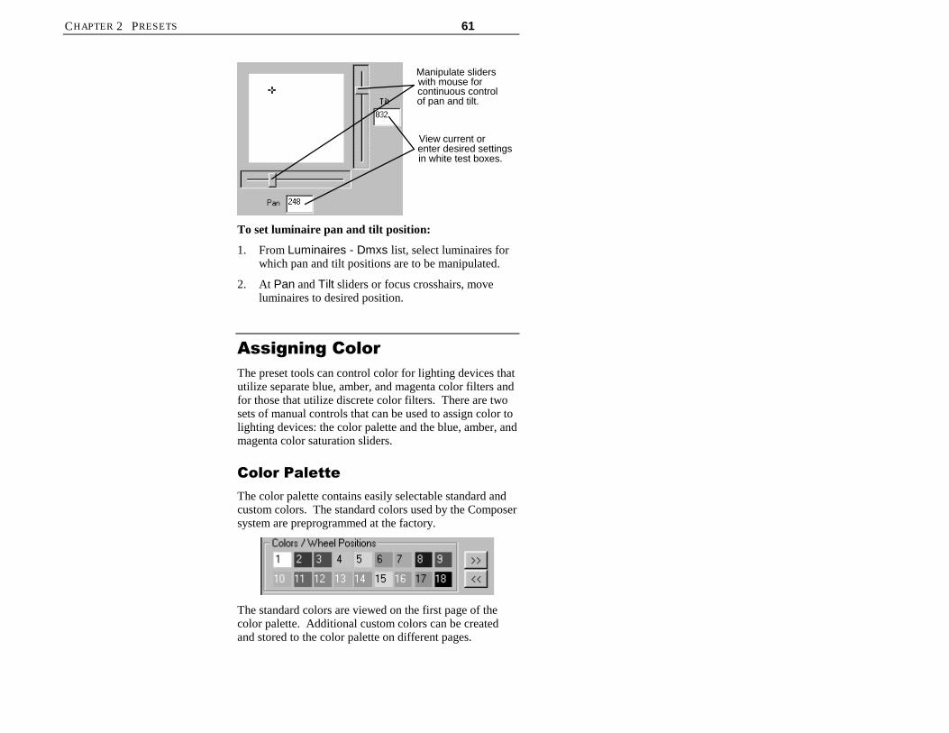
CHAPTER 2 PRESETS 61
Manipulate sliderswith mouse forcontinuous controlof pan and tilt.
View current orenter desired settingsin white test boxes.
To set luminaire pan and tilt position:
1. From Luminaires - Dmxs list, select luminaires forwhich pan and tilt positions are to be manipulated.
2. At Pan and Tilt sliders or focus crosshairs, moveluminaires to desired position.
$VVLJQLQJ�&RORU
The preset tools can control color for lighting devices thatutilize separate blue, amber, and magenta color filters andfor those that utilize discrete color filters. There are twosets of manual controls that can be used to assign color tolighting devices: the color palette and the blue, amber, andmagenta color saturation sliders.
&RORU�3DOHWWH
The color palette contains easily selectable standard andcustom colors. The standard colors used by the Composersystem are preprogrammed at the factory.
The standard colors are viewed on the first page of thecolor palette. Additional custom colors can be createdand stored to the color palette on different pages.

62 ETC COMPOSER PC SOFTWARE USER’S GUIDE
The buttons can page you forwards andbackwards through the pages to allow you to display thecolor you want to select. When you bring up a new colorpalette page, the colors assigned to that page will bevisible on your desktop. There are a total of three colorpalette pages.
Luminaires Utilizing Blue, Amber and MagentaFilters
For luminaires with separate blue, amber, and magentacolor filters, these filters can be combined to produce farmore colors than shown on the standard palette. Refer tothe Color Settings Appendix at the back of this manual fora listing of several dozen additional colors and theirsettings as well as a log for recording color settings youmay create.
Luminaires With Discrete Filters (Effects Wheels)
For luminaires with discrete color filters, the color paletteserves a slightly different role. Effects Wheel #1(typically color) has nine positions, controlled by the ninecolor/wheel positions shown on the top row of the colorpalette. Effects Wheel #2 (typically image patterns) alsocontains nine positions, controlled by the nine color/wheelpositions shown on the bottom row of the color palette. Inthe case of both effects wheels, position number 1 is open(no color and/or no pattern). The second and third colorpalette pages may be customized to store unique filterwheel positions. It is possible to store a filter position thatis between two discrete filters producing a unique coloreffect derived from each of the two filters.

CHAPTER 2 PRESETS 63
&RORU�6DWXUDWLRQ�6OLGHUV���:KHHO
&RQWURO
The color saturation sliders / wheel controls are used toselect desired colors. The controls perform this task indifferent ways, depending on which type of color systemis used in the luminaire to be controlled. In luminaireswith separate blue, amber, and magenta color filters, thesliders control the color saturation of each filter. Inluminaires with discrete filters, the blue and amber sliderseach control a filter wheel to move a chosen filter into thelight path.
Luminaires Utilizing Blue, Amber and MagentaFilters
There are three color saturation sliders, one for each maincolor component: blue, amber, and magenta. Each of thethree color sliders is graduated into 256 discrete steps,where 0 is lowest color saturation and 255 is maximumcolor saturation.
Manipulate slider withmouse for continuouscontrol over saturation.
Type desired saturationvalue or view currentsetting in white text box.
Luminaires With Discrete Filters (Effects Wheels)
For luminaires with discrete filters (color and/or patterneffects wheels), the Blue and Amber Color SaturationSliders serve a different purpose. The color sliders aregraduated into 256 discrete steps. The blue slider controlsrotation of effects wheel 1 and the amber slider controlsrotation of effects wheel 2. The magenta slider serves nopurpose in this type of luminaire. As the sliders aremoved from positions 0 through 255 the effects wheels
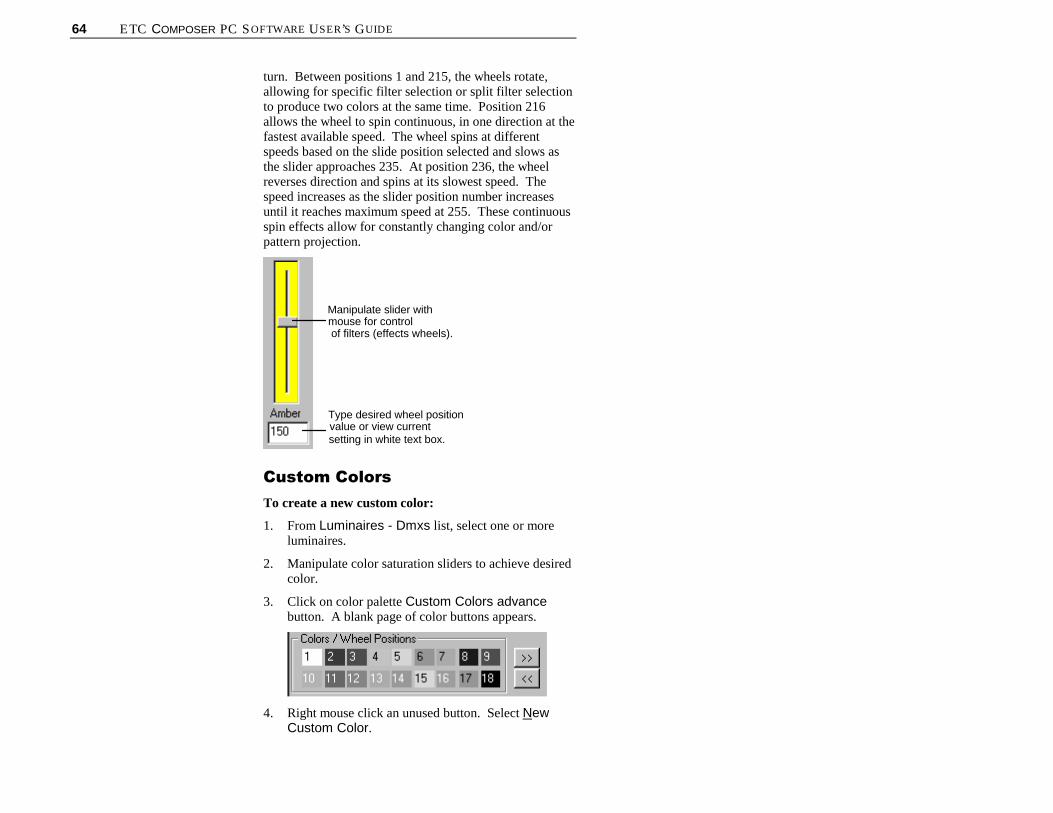
64 ETC COMPOSER PC SOFTWARE USER’S GUIDE
turn. Between positions 1 and 215, the wheels rotate,allowing for specific filter selection or split filter selectionto produce two colors at the same time. Position 216allows the wheel to spin continuous, in one direction at thefastest available speed. The wheel spins at differentspeeds based on the slide position selected and slows asthe slider approaches 235. At position 236, the wheelreverses direction and spins at its slowest speed. Thespeed increases as the slider position number increasesuntil it reaches maximum speed at 255. These continuousspin effects allow for constantly changing color and/orpattern projection.
Manipulate slider withmouse for controlof filters (effects wheels).
Type desired wheel positionvalue or view currentsetting in white text box.
&XVWRP�&RORUV
To create a new custom color:
1. From Luminaires - Dmxs list, select one or moreluminaires.
2. Manipulate color saturation sliders to achieve desiredcolor.
3. Click on color palette Custom Colors advancebutton. A blank page of color buttons appears.
4. Right mouse click an unused button. Select NewCustom Color.

CHAPTER 2 PRESETS 65
5. At Name: field, enter name for color or acceptdefault name. You must have unique name for eachcustom color.
6. For AR6 luminaires, check box indicating whichwheel position custom setting applies to.
7. Click on Setup Chip>> to create screen color chip.This provides the opportunity to color the chosencustom button to help identify locations of customcolors created. Color dialog appears.
8. Click on color to assign as screen chip. You mayclick on Basic colors, Custom colors, or from colortable at right of dialog.
9. Click on Add to Custom Color. Then click on OKto return to Define Custom Color dialog.
10. At Define Custom Color dialog, click on OK todismiss dialog and return to main Composer screen.
To delete a custom color:
1. Right mouse click on custom color to be deleted.

66 ETC COMPOSER PC SOFTWARE USER’S GUIDE
2. Select Delete Custom Color. Once deleted, there isno undo feature.
$GMXVWLQJ�%HDP
(For luminaires with diffusion control)
The beam parameter specifies the size and sharpness ofthe beam emerging from the lighting device. When thesetting is zero (normal wash), the diffusion mechanismdoes not impinge on the light path. The result is a normal,collimated beam. When the setting is maximum diffusion,the widest beam angle allowed by the lens is provided.
The preset tools expresses beam control as a value ofmaximum diffusion. The diffusion control is graduatedinto 256 discrete steps, where 0 is least diffusion and 255and is maximum diffusion.
You may select lighting devices individually to specifyexact beam edge characteristics on a device-by-devicebasis. You may also select multiple channels, allowingadjustment of the diffusion for several devicessimultaneously.
Manipulate slider withmouse for continuouscontrol over beam.
Type desired beamvalue or view currentsetting in white text box.

CHAPTER 2 PRESETS 67
7LPLQJ�9DOXHVTiming values are set to tell a preset how long it shouldtake to make a transition. That is, the time it should taketo go from one look to another.
Timing is composed of two components: the transitiontime and the delay time. The transition time is the timethat it takes for a preset to fully execute. For example, ifyou assign a timing value to color, so that the colorchanges from red to yellow in 10 seconds, then 10seconds is the transition time.
Note: Luminaires utilizing fixed color filters may have to passthrough unintended colors in their transition from one color toanother. This should be taken into account when setting transitiontimes.
You can also specify a delay time, which is the length oftime a parameter will wait before executing the start of theparameter transition. For example, if you set the colortiming for 10 seconds and then also specify a delay timefor color of 5 seconds, when the preset is executed thelighting device will wait 5 seconds before beginning thecolor change.
Reminder: It is important to remember that the totaltiming for this preset is 15 seconds, 10 for the colortransition and 5 seconds for the delay. When creatingsequences you will need to specify a preset follow time,which needs to be as long as the total timing for a presetto ensure that the preset is fully executed.
All timing values are entered in the Timing section of thepreset tools screen or in the grid.
All timing values are entered in minutes and seconds andcan be specified individually for all four lightingparameters: intensity (I), color (C), focus (F), and beam(B).
A single delay time is specified in minutes and secondsand then the specific lighting parameters to be delayed

68 ETC COMPOSER PC SOFTWARE USER’S GUIDE
have their check box marked. All or none of theparameters can be delayed.
The maximum duration for any timing value is 59 minutes30 seconds. Resolution for timing values is as follows:
Timing Resolution
1 sec. Through 4 min 15 sec 1 second resolution
4 min. 16 sec. - 42 min. 20 sec. 10 second resolution
42 min. 20 sec. - 59 min. 30 sec. 1 minute resolution
3UHVHW�3OD\EDFN�:LWK�DQG
:LWKRXW�7LPLQJ
When you select a preset, all luminaires respond bymoving to their target state. They will do so with orwithout their specified times values according to whether
the button is pressed. When the button ispressed (the default setting), timing is activated, meaningthat when you playback the preset, all timing values will
be fully activated. When you press the button againto turn off timing, when a preset is executed, there will beno timing associated with it. This allows you to test yoursystem without having to wait up to 1 hour for a preset tobe fully executed. When timing is turned off, eachparameter will complete its action as quickly as it can
7LPLQJ�([DPSOH
The following illustration represents an example of therelationship between transition and delay times for apreset. The illustration shows the behavior of the systemif timing settings were specified as such:
Transition times:• Intensity - 12 seconds• Focus - 5 seconds• Color - 5 seconds

CHAPTER 2 PRESETS 69
Delay time applied to color parameter: 10 seconds
DestinationTransition
Delay
Legend
5 10 15
Delay Time
Trigger
Intensity
Focus
Color
PresetDestination
The behavior of the example when the preset is recalledare as follows:
• At the moment when preset is executed, intensity andfocus begin their transitions immediately.
• The transition is from the current motor position tothe final target state.
• Focus reaches its target after 5 seconds.
• Intensity reaches its target after 12 seconds.
• Color does nothing until the 10-second delay iscomplete.
• After the delay time, color begins its transition.
• Color transition time is 5 seconds.
• The entire preset reaches its target in 15 seconds.

70 ETC COMPOSER PC SOFTWARE USER’S GUIDE
&UHDWLQJ�1HZ�3UHVHW�%DVHG
RQ�+RPH�3UHVHW
1. Make sure that preset tools screen is started.
2. Starting from Home preset, select luminaires andadjust lighting parameters to achieve desired effect.
a. Set intensity values.
b. Set pan and tilt positions.
c. Set blue, amber, and magenta color saturation, orselect color from color palette.
d. Set beam values.
e. Assign timing, both transition and delay asnecessary.
3. At main toolbar, click (Store As) button to storepreset. Store Preset Named… dialog appears.
4. Enter name for preset or accept default name. Givepreset unique name; you can not have two presets thathave same name.
5. Press Enter or click OK. Preset name is added toPresets list.
&UHDWLQJ�1HZ�3UHVHW�%DVHG
RQ�([LVWLQJ�3UHVHW
Frequently, you will want to base a new preset on thevalues of another preset, one that looks much like thepreset that you want to create. This enables quickerediting.
1. Adjust lighting parameters to achieve desired effect.
Note: When you use Store As, changes to original presetare not stored with that preset. They are only stored innew preset.
2. At main toolbar, click (Store As) button to storepreset with new name.

CHAPTER 2 PRESETS 71
The Store Preset Named… dialog appears.
3. Enter name for preset or accept default name.
4. Click OK or press Enter. Preset name is added toPresets list.
(GLWLQJ�([LVWLQJ�3UHVHW
At times you may want to edit existing presets. To do so,just start the preset tools, click on the preset to be editedfrom the Presets list and make your changes. You canthen save the changes to overwrite the existing presetname or assign a new name to create a new preset.
1. At Presets list, click on preset to be edited.
2. Manipulate lighting parameters to achieve desiredeffect.
3. At main toolbar, click button to overwrite preset
or click button to store preset with new name.
Alternately, you can select Store Preset from mousepopup menu.
'HOHWLQJ�3UHVHWV
At times you may want to delete existing presets. Whenyou need to, there are three ways in which to do so.
1. At Presets list, click on preset to be deleted.
2. At main toolbar, click on (Delete) button.Deletion warning dialog appears.

72 ETC COMPOSER PC SOFTWARE USER’S GUIDE
Alternately, you can select Delete Preset frommouse popup menu.
Alternately, you can select Delete from Edit menu.
CAUTION: Once preset is deleted, it will be deletedfrom all sequences, templates, schedules, global scripts,global templates, and event lists. If you undo deletion,preset will be added back to Presets list, but not into theactivities utilizing the preset. You will have to edit eachto add the preset back in.
3. Click Yes to complete preset deletion. Press No ifyou change your mind and don’t want to deletepreset.
If you delete preset by mistake, you can click on (Undo Delete) button on main toolbar to undodeletion.
5HFDOLEUDWLQJ�/LJKWLQJ
'HYLFHV
Luminaires contain their own internal calibration routines.You may invoke this routine from the Recalibrate menuselection from the Control menu.
When selected luminaires are calibrated, they move all oftheir motors through a pre-defined calibration sequence.At the conclusion of the sequence, the luminaires adopttheir Home position.
Note: The calibration sequence takes about 15 seconds. Duringcalibration, luminaires do not respond to any commands.
Tip: Use the recalibratefeature to correct thepositioning of a luminaire thatloses its place or is knockedout of position.

CHAPTER 2 PRESETS 73
(PHUJHQF\�3UHVHWThe Emergency preset is similar to the Home preset inthat it is also stored in an ETC luminaire. If programmed,the Emergency preset is automatically invoked when theluminaire loses control communication for five minutes.When that happens, assuming power is still provided tothe lighting system, the lighting devices will assume theEmergency preset position.
If there is no emergency preset programmed, the lightingdevices will remain in their current state until the controlsignal has been restored.
To create Emergency preset:
1. Make sure that preset tools screen is started andplayback toolbar is displayed.
2. Adjust manual controls to create Emergency preset.
3. From Control menu, choose Default Presets.
4. Select Store Emergency.
You can select Play Emergency from Control menuDefault Presets to send selected lighting devices toEmergency preset values.

74 ETC COMPOSER PC SOFTWARE USER’S GUIDE
To edit Emergency preset:
1. Make sure that preset tools screen is started andplayback toolbar is displayed.
2. Play back Emergency preset by choosing DefaultPresets from Control menu and then choosing PlayEmergency.
3. Adjust manual controls to edit Emergency preset todesired values.
4. From Control menu, choose Default Presets.
5. Select Store Emergency. New preset values areassigned as Emergency preset.
To delete Emergency preset:
1. Make sure that preset tools screen is started andplayback toolbar is displayed.
2. From Control menu, choose Default Presets.
3. Select Clear Emergency. Emergency preset iscleared.
Note: Once cleared, there is no undo feature for emergencypreset.

75
&KDSWHU���
6HTXHQFHV
A sequence is a collection of presets that are recalled oneafter another—in sequence—to create a dynamic lightingeffect. Sequences are managed using the sequence tools.A sequence is made up of the sequence main body (the listof presets), preset follow times, looping logic, and the endstate.
Sequences may be automatic or stepped. Playback of asequence is, by default, automatic. Each preset runssequentially until the sequence is fully executed. Steppedsequences allow each preset to be executed by a buttonpress from a remote control station. The process forcreating sequences is identical for stepped and automaticsequences. The only difference is the method ofplayback. Stepped sequences are useful for theater-likeshows, where presets are treated like cues, and a remotecontrol station button provides the “Go Next” function.
6HTXHQFH�7RROVThe sequence tools are the tools that you use to create andedit sequences. The tools are available from the maintoolbar and from the drop-down menus.
You must have your project file open and configuredbefore you can work with sequences. The file containsyour system configuration and all of the lighting eventsthat will be required to create sequences.
Sequence Tools button ontoolbar.

76 ETC COMPOSER PC SOFTWARE USER’S GUIDE
6WDUWLQJ�6HTXHQFH�7RROV
1. Make sure that Composer application is running andyour lighting project file is open.
2. At main toolbar click button. Sequence toolsscreen appears.
Alternately, from Program menu, chooseSequences.
*HWWLQJ�)DPLOLDU�ZLWK
6HTXHQFH�7RROV�6FUHHQ
In addition to the main and playback toolbars, thesequence tools contains several windows that open bydefault to allow for creating, editing, and maintaining yoursequence:
• Editor toolbar
• Sequences list
• Sequence Main Body field
• Preset Follow Time fields
• Loop fields
• Sequence End State fields
• Presets list.
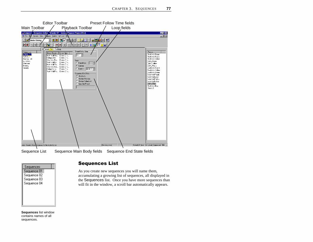
CHAPTER 3. SEQUENCES 77
Main Toolbar
Sequence List
Editor ToolbarPlayback Toolbar
Preset Follow Time fieldsLoop fields
Sequence Main Body fields Sequence End State fields
6HTXHQFHV�/LVW
As you create new sequences you will name them,accumulating a growing list of sequences, all displayed inthe Sequences list. Once you have more sequences thanwill fit in the window, a scroll bar automatically appears.
Sequences list windowcontains names of allsequences.

78 ETC COMPOSER PC SOFTWARE USER’S GUIDE
3UHVHWV�/LVW
As you create new presets you will name them,accumulating a growing list of presets, all displayed in thePresets list. Once you have more presets than will fit inthe window, a scroll bar automatically appears.
6HTXHQFH�0DLQ�%RG\
You create sequence by dragging preset names into thesequence main body and then assigning a preset followtime, looping logic, and the sequence end state. The orderin which the presets are listed in the sequence main bodyis the order in which they are played back. A total of1000 presets can be added to the sequence main body.
3UHVHW�)ROORZ�7LPH
The follow time determines the length of time that thepreset is to be active before the next preset is executed.The default follow time is 1 second.
The follow time begins counting at the moment the presetfirst begins to play. For this reason, you need to makesure that your preset follow time is equal to or greater thanthe total timing of the preset. Otherwise, the followingpreset may begin before the currently playing preset iscompletely executed.
Note: A stepped sequence ignores follow time andinstead is executed by the next button push.
Preset Follow Time isentered in minutes andseconds.
Sequence Main Body listsnames and order of presets tobe included in sequence.
Presets list window containsnames of all presets.

CHAPTER 3. SEQUENCES 79
/RRSLQJ�/RJLF
Looping logic is used to define the number of times orlength of time that a sequence is to be repeated. Use theradio buttons to the right of the sequence main body dataarea to specify your looping options for the sequence.The looping logic applies to the entire sequence and not toindividual presets. The default setting for looping logic isforever.
Repetitions Allows you to have sequence loop aspecified number of times. This givesyou a controlled sequence that will exit ina predictable way. The number ofrepetitions must be at least one, as thatnumber represents the first time throughthe main body. The maximum number ofrepetitions is 255.
Forever Allows you to loop the sequenceindefinitely. Only four actions willinterrupt a sequence when Forever isselected:
• You push a remote control stationbutton, thereby activating a newpreset or sequence.
• A station closure activates a newpreset or sequence.
• A scheduled calendar activityactivates a preset or sequence.
• You push (Stop) button onplayback toolbar.
Duration Allows you to loop the sequence for aspecified length of time, regardless of anyrepetitions. When you select Duration,you will have to enter the length of theduration in hours, minutes, and seconds.The maximum duration is 23 hours 50minutes 00 seconds.
Loop fields assign loopinglogic for entire sequence.
Refer to chapters on remotecontrol station templates andcalendar later in this manualfor more information onactivating a station closure orschedule.

80 ETC COMPOSER PC SOFTWARE USER’S GUIDE
(QG�6WDWH
Once the sequence is completely executed, including anylooping, the sequence adopts its end state. Use the radiobuttons to the right of the Sequence Main Body tospecify your end state option for the sequence. Thedefault end state is Hold As Is.
Hold As Is This end state will leave your lightingsystem in the same configuration thatexists when the last preset is executed.
RestorePrevious
This end state will restore your lightingsystem to the preset that was runningbefore the sequence was executed.
RestoreScheduled
This end state will restore your lightingsystem to schedule that was runningbefore the sequence was executed.
SpecifiedPreset
This end state will restore your lightingsystem to a specific preset.
Sequence End State willdefine what the sequence willlook like after it is completelyexecuted.

CHAPTER 3. SEQUENCES 81
&UHDWLQJ�DQG�0DQDJLQJ�6HTXHQFHVTo create a sequence, you will first assemble the order ofthe presets and assign follow times and then assignlooping logic and an end state.
&UHDWLQJ�6HTXHQFHV
1. Make sure that Composer application is running andthat required project file is open.
2. At main toolbar, click button to open sequencetools.
3. At Presets list, click on first preset to be in sequenceand while holding left mouse button, drag and droppreset name into Sequence Main Body. Cursorchanges to show plus (+) sign to show preset name isbeing copied into Sequence Main Body.
Alternately, you can click on preset to be added and
then click button on editor toolbar.
4. At Sequence Main Body, click on the preset nameto make it active.
5. At Preset Follow Time, enter follow time (minutesand seconds) for preset.
6. Continue adding presets (and their follow times) toSequence Main Body until sequence is complete.
Remove presets from Sequence Main Body byclicking on preset name in Sequence Main Body
and clicking button.
Clear all presets from Sequence Main Body by
clicking button.
7. At Loop, enter looping logic you desire for entiresequence.
8. At Sequence End State, specify how you wantsequence to look after it is completely executed.

82 ETC COMPOSER PC SOFTWARE USER’S GUIDE
9. Store your sequence.
a. Click button if you want to overwriteexisting sequence. Overwrite warning dialogappears.
At dialog box, click Yes to overwrite sequence.Click No to dismiss dialog and not overwritesequence.
b. If you based your sequence on an existingsequence and you do not want to overwrite
existing sequence, click button to storesequence as another name. Store SequenceNamed… dialog appears.
Enter sequence name or accept default name andclick OK.
(GLWLQJ�6HTXHQFHV
You edit an existing sequence much the way you createdit. Clicking on the sequence in the Sequences listdisplays the Sequence Main Body and its assignments.
To edit sequence:
1. Make sure that Composer application is running,required project file is open, and sequence tools arestarted.
2. At Sequences list, click on sequence to be edited.Sequence Main Body and its components aredisplayed.

CHAPTER 3. SEQUENCES 83
3. Make changes to Sequence Main Body asnecessary.
a. Add presets by dragging and dropping them fromPresets list
Remove individual presets by clicking on preset
and at playback toolbar, clicking button.
Remove all (clear) presets from Sequence Main
Body by clicking on button at playbacktoolbar.
Reorder presets by dragging and droppingpresets to new position. New position will beunder (after) highlighted preset.
b. Modify Preset Follow Time by clicking onpreset to make preset active, and then adjustingfollow time.
c. Modify Loop setting and/or Sequence EndState.
Note: If you attempt to select a different sequence aftercreating or changing another, Store Changes warningdialog appears.
Click Yes to overwrite existing sequence. If you clickNo, overwrite warning dialog appears.
4. Store your sequence changes by clicking on button. Overwrite dialog appears.

84 ETC COMPOSER PC SOFTWARE USER’S GUIDE
Click Yes to overwrite existing sequence and savechanges or click No to dismiss dialog without savingchanges.
'HOHWLQJ�6HTXHQFHV
Sequences can be easily deleted. Unlike adding or editingsequences, you do not have to have the sequence toolsopen to delete a sequence. You just have to be able toview the Sequences list. You can view the Sequenceslist from any Composer screen by selecting Sequencesfrom the View menu.
To delete sequence:
1. Make sure Sequences list is visible. If it is not,from View menu select Sequences.
2. At Sequences list, click on sequence to be deleted.
CAUTION: Once sequence is deleted, it will be deletedfrom all templates, schedules, global scripts, globaltemplates, and events. If you undo deletion, sequence willbe added back to Sequence list, but not into the activitiesutilizing the sequence. You will have to edit each to addthe sequence back in.
3. At main toolbar, click on button. Deletionwarning dialog appears.
Click Yes to continue with delete. Click No todismiss window and not delete sequence.
If you delete sequence by mistake, you can click on
(Undo Delete) button on main toolbar to undodeletion. Activities utilizing the sequence will not berestored.
Delete button on toolbar.

CHAPTER 3. SEQUENCES 85
6WHSSHG�6HTXHQFHV
Sequences can be assigned to button presses at a remotecontrol station. Each button press will advance thesequence one step (or one preset). A stepped sequencehas its constituent presets executed one after the other,just as with an automatic sequence, but only when aremote control station button is triggered. This providesmanual control over sequences from the button stations.Remember that a stepped sequence ignores follow times.
Note the following for stepped sequences:
• If a second recall station button is pressed before thefirst preset reaches its target state, the second presetbegins its transition immediately, halting the partiallycomplete preset in mid-transition
• If the sequence is interrupted by a press of a differentbutton or by a clock/calendar event, and the buttonassociated with the sequence is then pressed again,the sequence will start over from the beginning. Thesystem exhibits no memory of its position within astepped sequence that is interrupted.
• If the sequence looping logic specifies LoopForever, the sequence will never reach its end state.Rather, a press of the button from the final presetstarts the sequence over with the first preset. Thesequence main body thus repeats indefinitely. This isa good method for providing a circular queue ofmultiple presets via a single button.
• If the sequence looping logic specifies a certainnumber of repetitions, multiple button presses willrepeat the sequence until the specification is met.After the last time through, the sequence will adopt itsend state, ignoring subsequent button presses.
• If the sequence looping logic specifies a duration,multiple button presses will repeat the sequence untilthe duration time is up. Once the timer is exhausted,the sequence will adopt its end state, halting thesequence in mid-transition and ignoring subsequentbutton presses.
Tip: Because you mayuse sequences in eitherautomatic or steppedmode according to howyou activate them, youshould edit your sequenceto include appropriatefollow times, even if theyare primarily intended to bestepped.

86 ETC COMPOSER PC SOFTWARE USER’S GUIDE
For Example:
Stepped sequences are useful where a 2 button remotecontrol station configuration is used. Consider thefollowing scenario:
1. A sequence of presets called “fashion show”represents a list of lighting looks that will be playedsequentially as lighting cues for a show.
2. The sequence is dropped onto one button of the 2button remote control station with the StepSequence to next preset station command. Thisbutton will be used to step the sequence through thecues during the show.
3. The sequence is dropped onto a second button withReset Sequence to first preset command. Thisbutton will reset the lighting system to the top of thecue list.
4. The operator presses the first button to run rehearsalsor the show. To start over, the operator presses thesecond button.
5. For long or complex shows, the lighting might bebroken into four separate sequences. An 8 buttonrecall station could then be used since it supports fourStep Sequence to next preset and four ResetSequence to first preset commands, allowing easymanagement of the show.
Note: This example also applies to momentary closureswitches. By using two DMX channels connected to non-dims, one to step through a sequence and the other torestart the sequence, you can achieve automatic control.
&UHDWLQJ�6WHSSHG�6HTXHQFHV
1. Create sequences as described earlier.
2. Assign sequence to template button as describedearlier in this chapter.
3. At Sequence Commands screen, select ResetSequence to first preset. This will provide abutton to reset sequence to its beginnng.
4. Assign sequence to a different template button and atSequence Commands screen, select Step

CHAPTER 3. SEQUENCES 87
Sequence to next preset. This will be the button tostep the sequence through the individual presets.
(YHQW�/LVWV
Events are very similar to stepped sequences. Event Listsare composed of presets, and sequences. The individualsteps may initiate an individual preset or an entiresequence. Each step will initiate the next sequence orpreset designed into the event list.
1. Using the events button on the toolbar, activatethe Events editor screen.
2. Drag and drop presets and sequences into the eventsmain body and save in the same method as whencreating presets and sequences.
3. Open templates as described in the Creating NewTemplate section of this chapter.
4. Assign events from the Events list to the templateusing the same technique described earlier forassigning sequences.

88 ETC COMPOSER PC SOFTWARE USER’S GUIDE
(This page intentionally blank)

89
&KDSWHU���
7HPSODWHV
Templates are used to assign actions to remote controlstations. The remote control station provides controlcapability to those people who will be occupying thespace and recalling the lighting looks. There are fivedifferent remote control stations:
• 2 button recall station
• 8 button recall station
• Closure station
• Receptacle station
• Key station.
Note: The receptacle station and key station are notprogrammable remote control stations and do not have tobe configured.
The template specifies one or more actions that will occurwhen buttons are touched or when switches toggle. Asingle template contains all actions associated with everybutton or switch at a given remote control station. Onlyone template may be assigned to a station at one time.
A template itself does nothing. You must assign it to aremote control station. Changing templates is usuallydone with the clock/calendar, although you may also usebuttons or switches to assign templates.
Lighting Actions/System Commands
There are two kinds of actions that can be assigned to atemplate: lighting actions and system commands.Lighting actions recall presets, sequences, or event listsand system commands change an internal system state.Although multiple commands are allowed, you may droponly one preset, sequence, or event list into an action list.

90 ETC COMPOSER PC SOFTWARE USER’S GUIDE
System commands include power on/off, new templateassignment, and lock/unlock stations, and scheduleenable/disable.
8 Button and 2 Button Remote Control Stations
Button stations are used to manually execute events thatare programmed to the buttons. When you build one ormore templates for one of the button stations, you arespecifying what will happen when you press one of thebuttons.
Closure Stations
Closure stations are designed for automatic operation,supporting many types of dry contact switches, eithermomentary or maintained. By connecting these switchesto your closure station, programmed lighting actions maybe triggered when the switches are opened or closed bynormal daily activities.
Some of the switch placements and types that mayeffectively control lighting via closure stations include:
• Opened or closed doors
• Partition switches associated with room dividers
• Photo beams
• Motion detectors
• Floor mat switches.
Receptacle Stations
Receptacle stations are wall-mounted communicationslinks to the Composer control system. By connecting yourPC to this station, you may control your lighting systemvia Composer software. Although this component is aremote control station, you can not assign a template to it.It just needs to be configured so that an address can beassigned to it.
Station Configuration
Note: You must configure a remote control station beforeyou can assign a template to it.
As physical devices, remote control stations must beconfigured in much the same way as luminaires.Configuration entails specifying a name for each physicalremote control station, as well as its physical address andtype. Refer to Chapter One for configuration procedures.

CHAPTER 4. TEMPLATES 91
Template Tools button ontoolbar.
7HPSODWH�7RROVThe template tools are used to create and edit remotecontrol station templates. You build a remote controlstation template by dragging a lighting action onto atemplate button or by adding station commands.
You must have your project file open and configuredbefore you can work with templates. The file containsyour system configuration and all of the remote controlstations, sequences, presets, and events that will berequired to create the templates.
6WDUWLQJ�7HPSODWH�7RROV
1. Make sure that Composer application is running andyour lighting project file is open.
2. At main toolbar click button. Template toolsscreen appears.
Alternately, from Program menu, chooseTemplates.
*HWWLQJ�)DPLOLDU�ZLWK
7HPSODWH�7RROV�6FUHHQ
In addition to the main toolbar, the template tools containsseveral windows that open by default to allow forcreating, editing, and maintaining your templates:
• Editor toolbar
• Templates list
• Remote Control Stations list
• Presets list
• Sequences list
• Remote control station action list

92 ETC COMPOSER PC SOFTWARE USER’S GUIDE
• Template Type fields.
• Event list
Main Toolbar Editor Toolbar Remote Station Action list Preset list
Local Stations list Event list Template list Sequence list
5HPRWH�6WDWLRQ�$FWLRQ�/LVW
The remote station action list is located under the graphicrepresentation of the remote control station. The actionlist displays all of the events for which a recall stationbutton is assigned. Items are added to the action list byselecting them and dragging and dropping them into theaction list.

CHAPTER 4. TEMPLATES 93
(GLWRU�7RROEDU
In addition to the Remove Item and Clear buttons, theeditor toolbar contains the station command buttons.These buttons allow you to add power, schedule, andremote station commands, and to add presets, sequencesand events to the action list.
Add Power Command Button
Use this command to turn lighting devices on or off. Youcan add two power commands to each recall stationbutton: one for power on and one for power off. You cancontrol the power to individual or all lighting devices. Asecondary dialog will appear with you select thiscommand to select the operation you want to complete.
You select luminaires from the list on the left and thenclick on the On or Off buttons. You can select individualluminaires or groups of luminaires. Click OK to completethe operation and dismiss the dialog.
To edit a power command list, double click on the actionitem in the action list. Light Switch Dialog will reappear.

94 ETC COMPOSER PC SOFTWARE USER’S GUIDE
Add Schedule Command Button
Use this command to add a schedule command to a recallbutton or closure station. When the schedule commandbutton is activated, a secondary dialog box appears tohave you select the type of schedule command.
The Disable Schedule for field allows you to disable aschedule for a specific length of time, in hours andminutes. The maximum time allowed for a schedule to bedisabled is 23 hours 50 minutes.
The Disable Schedule command disables a scheduleindefinitely. The only way to re-enable a schedule whenthe Disable Schedule command is used is with theEnable Schedule command.
The Enable Schedule command enables a schedule tobegin running.
Add Remote Station Command Button
Use this command to add a command that controls theoperation of a remote control station. When you drag anddrop a remote control station name onto a button or intothe action list, a secondary dialog appears to have youselect the type of remote station command.

CHAPTER 4. TEMPLATES 95
The Assign Template field allows you to assign aspecific template to the specified remote station whentriggered from a recall (remote) or closure station. Whenyou select this command you must enter the templatename in the field to the right. The drop-down arrow willallow you to scroll through your template names.
The Lock Station for command allows you to lock astation for a specific length of time. A locked station willnot allow any manual control. This is usually used toprevent tampering with lighting controls. When you clickon this radio button, you will have to specify the length oftime in hours and minutes. The maximum length of timefor locking a station with this command is 23 hours and 50minutes. You can unlock a locked station using the Un-Lock Station command.
The Lock Station command is used to lock a station foran indefinite length of time, essentially permanentlylocking the station. The only way to unlock a station thathas been locked using the Lock Station command is withthe Un-Lock Station command from another remotestation or with MCP hard reset.
Use the Un-Lock Station command to allow stationcontrol of recall and closure stations locked using theLock Station for and Lock Station commands.

96 ETC COMPOSER PC SOFTWARE USER’S GUIDE
Add Sequence Button
Use this button to assign a sequence to a recall or closurestation. You use this command to allow for steppedsequences from a recall or closure station. When you dragand drop a sequence name onto a button or into the actionlist, a secondary dialog appears to have you select themethod of playback for the sequence.
The Recall Sequence using preset follow times radiobutton recalls the sequence with the follow time enabled.This is the default condition for recalling sequences froma recall or closure station. The preset follow times wereassigned from the sequences tools screen.
The Reset Sequence to first preset selection allowsyou to have a running sequence reset to the first preset ofthe sequence. This command allows you to step through asequence after resetting it to the beginning.
The Step Sequence to next preset command is used tocreate stepped sequences. When this command isenabled, button pushes from a recall station willindividually step through the preset assigned to thesequence on that button.
Add Preset Button
Use this button to assign a preset to a button on a recall orclosure station. When clicked, this button assigns theactive preset shown in the Presets list. You use thisbutton as you would if you were dragging and dropping apreset onto a button or into the action list.

CHAPTER 4. TEMPLATES 97
Add Event Button
Use this button to assign an event to a button on a recall orclosure station. When clicked, this button assigns theactive event shown in the Event list. You use this buttonas you would if you were dragging and dropping an eventonto a button or into the action list. Event Commandsappears as a secondary dialog, allowing you to select themethod of playback (automatic or stepped).
7HPSODWH�7\SHV
After selecting New Template, the Add RoomTemplate window appears.
Use these radio buttons to select the type of remotecontrol station for which you are creating a template.Note that only those remote control stations that can havea template assigned are listed in the Template Typesfields.

98 ETC COMPOSER PC SOFTWARE USER’S GUIDE
8 Button and 2 Button Recall Stations
These graphics represent the eight buttons and the twobuttons on these recall stations. You can assign lightingactions and station commands to the active button bydragging and dropping. You can also drag and droplighting events or assign station commands in the actionlist box located under the graphic. Click on a button tomake it active. Although you can only assign one presetor sequence to a buttons, you can stack several stationcommands onto a button.
Maintained Closure Station
This closure station template allows for lighting events orstation commands to be assigned to eight switches, with
each having an open ( ) and closed ( ) condition.
As an example, you could use this closure station templatewhen you want to have two lighting looks for a roombehind a door. When you open the door (open switchposition) the lighting devices come on and maybe trigger asequence. When you close the door (closed switchposition) power could be turned off to all luminaires.

CHAPTER 4. TEMPLATES 99
Momentary Closure Station
This closure station template allows for lighting events orstation commands to be assigned to eight switches. Forthese switches, the event is triggered by the action of theswitch, regardless of its position.
As an example, you could use this closure station templatewhen you want to have a lighting look for an entry way.When someone steps on the welcome mat (activating theswitch) you could have your lighting system power on andexecute a preset.
7HPSODWHV�/LVW
As with presets and sequences, you will refer to yourtemplates by name, with the names of stored templatesshown in the Templates list. Only one template can beassigned to a remote control station, even though you canhave several templates that will work at an 8 button recallstation, for instance. When you first start a project, notemplates exist. Once you have more templates than willfit in the window, a scroll bar automatically appears.
&UHDWLQJ�DQG�0DQDJLQJ�7HPSODWHVWhenever the template tools are open a template is alwaysselected as the active template. All editing activities applyto this selection. The rules for the active template are asfollows:
• The name of the active template is highlighted in theTemplates list.
• When you select an existing template (by pointingand clicking on its name) that template becomesactive.
• When you create a new template, the new templatebecomes active.

100 ETC COMPOSER PC SOFTWARE USER’S GUIDE
&UHDWLQJ�1HZ�7HPSODWH
1. Make sure that Composer application is running andthat required project file is open. Ensure desiredroom is selected.
2. At main toolbar, click button to open templatetools.

CHAPTER 4. TEMPLATES 101
3. Select New Template button. At Template Types,click on radio button for type of remote controlstation for which you will be creating template. ClickAdd. Remote control station template graphicappears.
4. Select items and drag and drop them onto templatebuttons or into action list.
Alternately, click on desired editor toolbar stationcommand button. Complete associated dialogs.
5. Remove events from action list by clicking on event
in action list and clicking button.
Remove all events from action list (all button
assignments) by clicking button.
6. Click button to store template
(GLWLQJ�([LVWLQJ�7HPSODWH
1. Make sure that Composer application is running andthat required project file is open. Ensure desiredroom is selected.
2. At main toolbar, click button to open templatetools.

102 ETC COMPOSER PC SOFTWARE USER’S GUIDE
3. At Templates list, click on template name to beedited to make it active. Template button graphicappears.
4. Toggle through buttons or action lists and makechanges as necessary.
5. Add actions by dragging and dropping or by usingeditor toolbar command buttons.
6. Remove individual actions using button andclear all button assignments (or all of action list
contents) using button.
Note: If you attempt to select different template aftercreating or changing another, Store Changes warningdialog appears.
Click Yes to overwrite existing template. If you click No,overwrite warning dialog appears.
7. Store template.
a. Click button if you want to overwriteexisting template. Overwrite warning dialogappears.
At dialog box, click Yes to overwrite template.Click No to dismiss dialog and not overwritetemplate.

CHAPTER 4. TEMPLATES 103
b. If you do not want to overwrite existing template,
click button to store template as anothername. Store Room Template dialog appears.
Enter template name or accept default name andclick OK.
'HOHWLQJ�7HPSODWHV
Unlike other template operations, to delete a template youhave to select it from the Templates list. This can bedone from any Composer application screen by selectingTemplates from View menu.
1. Make sure that Composer application is running andthat required project file is open.
2. At Templates list, select template to be deleted.
3. At main toolbar, click button. Alternately, clickon right mouse button to bring up mouser popupmenu and select Delete Template. Deletionwarning dialog appears.
4. Click Yes to continue with delete. Click No todismiss window and not delete template.
Delete button on toolbar.

104 ETC COMPOSER PC SOFTWARE USER’S GUIDE
If you delete template by mistake, you can click on
(Undo Delete) button on main toolbar to undodeletion.
'HIDXOW�7HPSODWHV
A default template is the remote recall station assignmentsthat are active when other specific templates are notinvoked. The template representing the actions most oftendesired would typically be assigned as default.
1. Create desired templates as described in previoussections.
2. Select desired remote station to house defaulttemplate and click on right mouse button. AssignDefault Template dialog appears.
Click on dialog to assign. Assignment dialog pop-upappears.
3. Select desired template from Default Template List.

CHAPTER 5. GLOBAL SCRIPTS 105
&KDSWHU���
*OREDO�6FULSWV
A global script represents a series of actions such aspresets, sequences, power commands (individualluminaire on/off for bulb only), local and global recallstation commands (lock, unlock, assign template), andglobal schedule commands (enable/disable schedule).The contents of global scripts may be pulled from anyroom.
You may have up to 1000 global scripts. A given scriptcan contain a maximum of 1000 separate systemactivities.
Global scripts may be automatic or stepped. Playback ofa script is, by default, automatic. Each preset or sequenceruns one after the other until the script is fully executed.Stepped scripts allow each activity to be executed by abutton press from a remote control station. The processfor creating global scripts is identical for stepped andautomatic scripts. The only difference is the method ofplayback. Stepped scripts are useful for theater-likeshows, where presets and sequences are treated like cues,and a remote control station button provides the ”GoNext” function.
Note: Presets are single lighting looks (position and color with orwithout timing). Sequences are a series of presets with timingvalues, played one after the other. Event lists can be a combinationof presets and sequences played one after the other and run from atemplate on a local recall station. Global Scripts are a grouping ofpresets or sequences, that have been assigned to individual roomsand combined to allow simultaneous control over multiple rooms.Other than events, any of the above lighting activities (presets,sequences, global scripts) can be assigned to a schedule to beactivated based on a predetermined time.
As an example, in a hotel environment where lights have beeninstalled in numerous rooms (such as lobby, gift shop, buffetbreakfast area, and conference area), each room will likely havebeen programmed to produce different lighting effects. All can berun simultaneously by creating a global script and assigning it tothe schedule to be activated at a predetermined time.

106 ETC COMPOSER PC SOFTWARE USER’S GUIDE
(This page intentionally blank)

CHAPTER 5. GLOBAL SCRIPTS 107
*OREDO�6FULSW�7RROVThe global script tools are the tools that you use to createand edit scripts. The tools are available from the maintoolbar and from the drop-down menus.
You must have your project file open and configuredbefore you can work with scripts. The file contains yoursystem configuration and all of the actions that will berequired to create scripts.
6WDUWLQJ�*OREDO�6FULSW�7RROV
1. Make sure that Composer application is running andyour lighting project file is open. Ensure desiredroom is selected.
2. At main toolbar click button. Global script toolsscreen appears.
*HWWLQJ�)DPLOLDU�ZLWK�*OREDO
6FULSW�7RROV�6FUHHQ
In addition to the main, editor, and playback toolbars, theglobal script tools contains several windows that open bydefault to allow for creating, editing, and maintaining yourscripts:
• Global Scripts list
• Presets list
• Local Stations list
• Global Stations list
• Sequences list
Global Script Tools buttonon toolbar.

108 ETC COMPOSER PC SOFTWARE USER’S GUIDE
Editor Toolbar Main Toolbar Playback Toolbar
Global Stations List Local Stations List Global Scripts
Presets ListSequences List
Main Body
Loop fields
Follow Time
*OREDO�6FULSWV�/LVW
As you create new global scripts you will name them,accumulating a growing list of scripts, all displayed in theGlobal Scripts list. Once you have more scripts than willfit in the window, a scroll bar automatically appears.Each time you start the scripts tools, the first script isselected.

CHAPTER 5. GLOBAL SCRIPTS 109
3UHVHWV�/LVW
As you create new presets you will name them,accumulating a growing list of presets, all displayed in thePresets list. Once you have more presets than will fit inthe window, a scroll bar automatically appears.
6HTXHQFHV�/LVW
As you create new sequences you will name them,accumulating a growing list of sequences, all displayed inthe Sequences list. Once you have more sequences thanwill fit in the window, a scroll bar automatically appears.
5HPRWH�6WDWLRQV�/LVWV��/RFDO�DQG
*OREDO�
As with presets and sequences, you will refer to yourremote control stations by name, with the names ofconfigured stations shown in the Remote Stations list.Once you have more templates than will fit in the window,a scroll bar automatically appears.
*OREDO�6FULSWV�0DLQ�%RG\
You create scripts by dragging preset, sequence, and eventnames from their lists into the global scripts main bodyand then assigning a follow time and looping logic. Theorder in which the presets and sequences are listed in thescripts main body is the order in which they are playedback. A total of 1000 activities can be added to the globalscripts main body.
*OREDO�6FULSWV�)ROORZ�7LPH
The follow time determines the length of time that thescript is to play before the next activity is executed.During that time, the activity can, in fact, play apreset/sequence, wait, or have the following activity beginits execution before the current activity has beencompletely executed. The default follow time is 1 second.
The follow time begins counting at the moment theactivity first begins. For this reason, you need to makesure that your script follow time is equal to or greater than

110 ETC COMPOSER PC SOFTWARE USER’S GUIDE
the total timing of the activity. Otherwise, the followingactivity may begin before the currently playing activity iscompletely executed.
Note: A stepped activity ignores follow time and insteadis executed by the next button push.
/RRSLQJ�/RJLF
Looping logic is used to define the number of times orlength of time that a script is to be repeated. Use the radiobuttons to the right of the script main body data area tospecify your looping options for the script. The loopinglogic applies to the entire script and not to individualactivities. The default setting for looping logic is forever.
Repetitions Allows you to have script loop a specifiednumber of times. This gives you acontrolled script that will exit in apredictable way. The number ofrepetitions must be at least one, as thatnumber represents the first time throughthe main body. The maximum number ofrepetitions is 255.
Forever Allows you to loop the script indefinitely.There are only two ways to interrupt ascript when Forever is selected:
• The user locks the room fromComposer.
• The user assigns a disable commandto a local or global template stationor a schedule.
Note: If using a local station to disable,only a local station command will re-enable.If using a global station script commandto disable, MCP controller commandswill be disabled, but local “Forever”sequences will continue until a localpreset command ends the “Forever”instruction. Global disables must beglobally re-enabled.
Loop fields assign loopinglogic for entire script.

CHAPTER 5. GLOBAL SCRIPTS 111
Duration Allows you to loop the script for aspecified length of time, regardless of anyrepetitions. When you select Duration,you will have to enter the length of theduration in hours, minutes, and seconds.The maximum duration is 23 hours 50minutes 00 seconds.
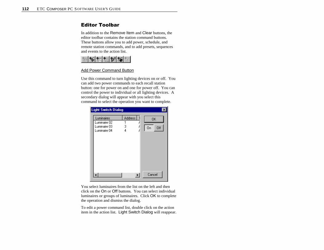
112 ETC COMPOSER PC SOFTWARE USER’S GUIDE
(GLWRU�7RROEDU
In addition to the Remove Item and Clear buttons, theeditor toolbar contains the station command buttons.These buttons allow you to add power, schedule, andremote station commands, and to add presets, sequencesand events to the action list.
Add Power Command Button
Use this command to turn lighting devices on or off. Youcan add two power commands to each recall stationbutton: one for power on and one for power off. You cancontrol the power to individual or all lighting devices. Asecondary dialog will appear with you select thiscommand to select the operation you want to complete.
You select luminaires from the list on the left and thenclick on the On or Off buttons. You can select individualluminaires or groups of luminaires. Click OK to completethe operation and dismiss the dialog.
To edit a power command list, double click on the actionitem in the action list. Light Switch Dialog will reappear.

CHAPTER 5. GLOBAL SCRIPTS 113
Add Schedule Command Button
Use this command to add a schedule command to a recallbutton or closure station. When the schedule commandbutton is activated, a secondary dialog box appears tohave you select the type of schedule command.
The Disable Schedule for field allows you to disable aschedule for a specific length of time, in hours andminutes. The maximum time allowed for a schedule to bedisabled is 23 hours 50 minutes.
The Disable Schedule command disables a scheduleindefinitely. The only way to re-enable a schedule whenthe Disable Schedule command is used is with theEnable Schedule command.
The Enable Schedule command enables a schedule tobegin running.
Add Remote Station Command Button
Use this command to add a command that controls theoperation of a remote control station. When you drag anddrop a remote control station name onto a button or intothe action list, a secondary dialog appears to have youselect the type of remote station command.

114 ETC COMPOSER PC SOFTWARE USER’S GUIDE
The Assign Template field allows you to assign aspecific template to the specified remote station whentriggered from a recall (remote) or closure station. Whenyou select this command you must enter the templatename in the field to the right. The drop-down arrow willallow you to scroll through your template names.
The Lock Station for command allows you to lock astation for a specific length of time. A locked station willnot allow any manual control. This is usually used toprevent tampering with lighting controls. When you clickon this radio button, you will have to specify the length oftime in hours and minutes. The maximum length of timefor locking a station with this command is 23 hours and 50minutes. You can unlock a locked station using the Un-Lock Station command.
The Lock Station command is used to lock a station foran indefinite length of time, essentially permanentlylocking the station. The only way to unlock a station thathas been locked using the Lock Station command is withthe Un-Lock Station command from another remotestation or with MCP hard reset.
Use the Un-Lock Station command to allow stationcontrol of recall and closure stations locked using theLock Station for and Lock Station commands.

CHAPTER 5. GLOBAL SCRIPTS 115
Add Sequence Button
Use this button to assign a sequence to a recall or closurestation. You use this command to allow for steppedsequences from a recall or closure station. When you dragand drop a sequence name onto a button or into the actionlist, a secondary dialog appears to have you select themethod of playback for the sequence.
The Recall Sequence using preset follow times radiobutton recalls the sequence with the follow time enabled.This is the default condition for recalling sequences froma recall or closure station. The preset follow times wereassigned from the sequences tools screen.
The Reset Sequence to first preset selection allowsyou to have a running sequence reset to the first preset ofthe sequence. This command allows you to step through asequence after resetting it to the beginning.
The Step Sequence to next preset command is used tocreate stepped sequences. When this command isenabled, button pushes from a recall station willindividually step through the preset assigned to thesequence on that button.
Add Preset Button
Use this button to assign a preset to a button on a recall orclosure station. When clicked, this button assigns theactive preset shown in the Presets list. You use thisbutton as you would if you were dragging and dropping apreset onto a button or into the action list.

116 ETC COMPOSER PC SOFTWARE USER’S GUIDE
&UHDWLQJ�DQG�0DQDJLQJ�*OREDO�6FULSWVWhenever the global script tools are open, a script isalways selected as the active script. All editing activitiesapply to this selection. The rules for the active script areas follows:
• The name of the active script is highlighted in theGlobal Scripts list.
• When you select an existing script (by pointing andclicking on its name) that script becomes active.
• When you create a new script, the new script becomesactive.
&UHDWLQJ�1HZ�*OREDO�6FULSWV
1. Make sure that Composer application is running andthat required project file is open. Ensure desiredroom is selected.
2. Make sure that global scripts tools are open.
3. Select items and drag and drop them onto GlobalScript Editor main body. Items appear in script listin order of selection and playback sequence.
Alternately, click on desired editor toolbar stationcommand button and complete associated dialogs.
CAUTION: Using button clears all scheduledactivities from entire script.
4. Remove activities from action list by clicking on
desired item and clicking button.
Remove all activities from entire script by clicking
button.
5. At Script Main Body, click on the action itemdesired to make it active.
6. At Step Follow Time, enter follow time (minutesand seconds) desired for action duration.

CHAPTER 5. GLOBAL SCRIPTS 117
7. Continue adding actions (and follow times) to ScriptMain Body until script is complete.
8. At Loop, enter looping logic desired for entire script.
9. Store script.
a. Click button to store. Store Global ScriptName dialog box appears. Name script oraccept default.
Click OK to store script. Click Cancel to disregard storecommand.
b. If new script is based on existing script and youdo not want to overwrite existing script, click
button to store script as another name.Enter script name or accept default and click OK.
(GLWLQJ�([LVWLQJ�*OREDO�6FULSW
You edit an existing script much the way you created it.Clicking on the script in the Global Script list displays theScript Main Body and its assignments.
To edit script:
1. Make sure that Composer application is running,required project file is open, and global script toolsare started.
2. At Global Scripts list, click on script to be edited.Scripts Main Body and its components aredisplayed.
3. Make changes to Script Main Body as necessary.
a. Add actions by dragging and dropping them fromdesired action lists.

118 ETC COMPOSER PC SOFTWARE USER’S GUIDE
Remove individual actions by clicking on action
and at playback toolbar, clicking button.
Remove all (clear) actions from Script Main
Body by clicking on button at playbacktoolbar.
Reorder actions by dragging and droppingactions to new position. New position will beunder (after) highlighted action.
b. Modify Step Follow Time by clicking on actionto make action active, and then adjusting followtime.
c. Modify Loop setting.
Note: If you attempt to select a different script aftercreating or changing another, Store Changes warningdialog appears.
Click Yes to overwrite existing script. If you click No,overwrite warning dialog appears.
4. Store your script changes by clicking on button.Overwrite dialog appears.
Click Yes to overwrite existing sequence and savechanges or click No to dismiss dialog without savingchanges.

CHAPTER 5. GLOBAL SCRIPTS 119
'HOHWLQJ�*OREDO�6FULSWV
Global Scripts can be easily deleted. Unlike adding orediting scripts, you do not have to have the scripts toolsopen to delete a scripts. You just have to be able to viewthe Scripts list. You can view the Scripts list from anyComposer screen by selecting Global Scripts from theView menu.
To delete script:
1. Make sure Global Scripts list is visible. If it is not,from View menu select Global Scripts.
2. At Global Scripts list, click on script to be deleted.
CAUTION: Once script is deleted, it will be deletedfrom all schedules and global templates. If you undodeletion, script will be added back to Global Scripts list,but not into the activities utilizing the script. You willhave to edit each to add script back in.
3. At main toolbar, click on button. Deletionwarning dialog appears.
Click Yes to continue with delete. Click No todismiss window and not delete sequence.
If you delete sequence by mistake, you can click on
(Undo Delete) button on main toolbar to undodeletion. Activities utilizing the script will not berestored.
$VVLJQLQJ�*OREDO�6FULSWV�WR
7HPSODWHV
Global Scripts may be assigned to Global templates or toschedules as an effective way to fully utilize the Composer
Delete button on toolbar.

120 ETC COMPOSER PC SOFTWARE USER’S GUIDE
system’s capabilities. Refer to chapters on Templates andSchedules for details on performing these operations.
6WHSSHG�6FULSWV
Scripts can also be assigned to button presses at a remotecontrol station. Each button press will advance the scriptone step (or one action). A stepped script has itsconstituent actions executed one after the other, just aswith an automatic script, but only when a remote controlstation button is triggered. This provides manual controlover scripts from the button stations. Remember that astepped script ignores follow times.
Note the following for stepped scripts:
• If a second recall station button is pressed before thefirst action reaches its target state, the second actionbegins its transition immediately, halting the partiallycomplete prior action in mid-transition.
• If the script is interrupted by a press of a differentbutton or by a clock/calendar activity, and the buttonassociated with the script is then pressed again, thescript will start over from the beginning. The systemexhibits no memory of its position within a steppedscript that is interrupted.
• If the script looping logic specifies Loop Forever,the script will never stop. Rather, a press of thebutton from the final action starts the script over withthe first action. The script main body thus repeatsindefinitely. This is a good method for providing acircular queue of multiple actions via a single button.
• If the script looping logic specifies a certain numberof repetitions, multiple button presses will repeat thescript until the specification is met. After the lasttime through, the script will halt, adopting its lastaction.
• If the script looping logic specifies a duration,multiple button presses will repeat the script until theduration time is up. Once the timer is exhausted, thescript will adopt its most recently executed action,halting the script in mid-transition and ignoringsubsequent button presses.
Tip: Because you mayuse scripts in eitherautomatic or steppedmode according to howyou activate them, youshould edit your script toinclude appropriate followtimes, even if they areprimarily intended to bestepped.
CHAPTER 5. GLOBAL SCRIPTS 121
For Example:
Stepped scripts are useful where a 2 button remote controlstation configuration is used. Consider the followingscenario:
1. A script of actions called “fashion show” represents alist of lighting looks that will be played sequentiallyas lighting cues for a show.
2. The script is dropped onto one button of the 2 buttonremote control station with the Step Global Script tonext command station command. This button willbe used to step the script through the cues during theshow.
3. The script is dropped onto a second button withReset Global Script to first command command.This button will reset the lighting system to the top ofthe cue list.
4. The operator presses the first button to run rehearsalsor the show. To start over, the operator presses thesecond button.
5. For long or complex shows, the lighting might bebroken into four separate scripts. An 8 button recallstation could then be used since it supports four StepGlobal Script to next command and four ResetGlobal Script to first command commands,allowing easy management of the show.
Note: This example also applies to momentary closureswitches. By using two DMX channels connected to non-dims, one to step through a script and the other to restartthe script, you can achieve automatic control.
&UHDWLQJ�6WHSSHG�6FULSWV
1. Create scripts as described earlier.
2. Assign script to template button as described earlierin this chapter.
3. At Global Scripts Commands screen, select ResetGlobal Scripts to first command. This will providea button to reset script to its beginning.
4. Assign script to a different template button and atGlobal Script Commands screen, select Step

122 ETC COMPOSER PC SOFTWARE USER’S GUIDE
Global Script to next command. This will be thebutton to step the script through the individualcommands.

CHAPTER 6. GLOBAL TEMPLATES 123
&KDSWHU���
*OREDO�7HPSODWHV
Global Templates are used to assign actions to globalremote control stations. Templates, as discussed in aprevious chapter, control single rooms. Global Templatesallow the user to control multiple rooms from one remotecontrol station. The contents of any individual room canbe added to a global template for control of that room. Aremote control station is a physical device, consisting ofone or more switches or manual buttons. The remotecontrol station provides control capability to those peoplewho will be occupying the space and recalling the lightingdesigns. There are five different remote control stations:
• 2 button recall station
• 8 button recall station
• Closure station
• Receptacle station
• Key station.
Note: The key station is not a programmable remotecontrol station and does not have to be configured.
The global template specifies one or more actions that willoccur at all lighting locations when buttons are touched orwhen switches toggle. A single template contains allactions associated with every button or switch at a givenremote control station. Only one template may beassigned to a station at any given time. A remote controlstation must be dedicated to either templates or globaltemplates, and cannot be used to control both.
A template itself does nothing. You must assign it to aremote control station. This is usually done with theclock/calendar, although you may also use buttons orswitches to assign templates.
124 ETC COMPOSER PC SOFTWARE USER’S GUIDE
Lighting Actions/System Commands
There are two kinds of actions that can be assigned to aglobal template: lighting actions and system commands.Lighting actions recall presets or sequences and systemcommands change an internal system state. Althoughmultiple commands are allowed, you may drop only onepreset or one sequence or one event into an action list.
System commands can also be assigned to globaltemplates. These commands include power on/off, newtemplate assignment, and lock/unlock stations, amongother commands.
8 Button and 2 Button Remote Control Stations
Button stations are used to manually execute events thatare programmed to the buttons. When you build one ormore global templates for one of the button stations, youare specifying what will happen when you press one of thebuttons.
Closure Stations
Closure stations are designed for automatic operation,supporting many types of dry contact switches, eithermomentary or maintained. By connecting these switchesto your closure station, you may design lighting eventsthat are triggered when the switches are opened or closedby normal daily activities.
Some of the switch placements and types that mayeffectively control lighting via closure stations include:
• Opened or closed doors
• Partition switches associated with room dividers
• Photo beams
• Motion detectors
• Floor mat switches.
Receptacle Stations
Receptacle stations are wall-mounted communicationslinks to the Composer control system. By connecting yourPC to this station, you may control your lighting systemvia Composer software. Although this component is aremote control station, you can not assign a template to it.It just needs to be configured so that an address can beassigned to it.

CHAPTER 6. GLOBAL TEMPLATES 125
Station Configuration
Note: You must configure a remote control station beforeyou can assign a template or global template to it.
As physical devices, remote control stations must beconfigured in much the same way as luminaires.Configuration entails specifying a name for each physicalremote control station, as well as its physical address andtype. Refer to Chapter One for configuration procedures.

126 ETC COMPOSER PC SOFTWARE USER’S GUIDE
Global Template Toolsbutton on toolbar.
*OREDO�7HPSODWH�7RROVThe global template tools are the tools that you use tocreate and edit remote control station templates. Youbuild a remote control station template by dragging alighting action onto a template button or by adding stationcommands.
You must have one of your project files open andconfigured before you can work with global templates.The file contains your system configuration and all of theremote control stations, sequences, and presets that will berequired to create the global templates. You will movefrom room to room as you assign actions to the globaltemplate.
6WDUWLQJ�*OREDO�7HPSODWH
7RROV
1. Make sure that Composer application is running andyour lighting project file is open.
2. At main toolbar click button. Global templatetools screen appears.
Alternately, from Program menu, choose GlobalTemplates.
*HWWLQJ�)DPLOLDU�ZLWK�*OREDO
7HPSODWH�7RROV�6FUHHQ
In addition to the main toolbar, the template tools containsseveral windows that open by default to allow forcreating, editing, and maintaining your global templates:
• Editor toolbar
• Global Templates list
• Global Scripts list

CHAPTER 6. GLOBAL TEMPLATES 127
• Presets list
• Sequences list
• Events list
• Local Remote control station list
• Global Remote control station action list
• Global Template Type fields.
Global Stations list Local Stations list Global Templates list
Main EditorAction list
Global TemplateToolbar Toolbar
GlobalScripts
PresetsSequences
Events list
*OREDO�7HPSODWH�$FWLRQ�/LVW
The global template action list is located under thegraphic representation of the remote control station. Theaction list displays all of the actions for which a recallstation button is assigned. Items are added to the action

128 ETC COMPOSER PC SOFTWARE USER’S GUIDE
list by selecting them and dragging and dropping theminto the action list.
(GLWRU�7RROEDU
In addition to the Remove Item and Clear buttons, theeditor toolbar contains the station command buttons.These buttons allow you to add Global scripts. power,schedule, and remote station commands, and to addpresets, sequences and events to the action list.
Add Global Script
Use this button to assign a global script to a button on arecall or closure station. Global Scripts are used only inconjunction with Global Templates and schedules.
Add Power Command Button
Use this command to turn lighting devices on or off. Youcan add two power commands to each recall stationbutton: one for power on and one for power off. You cancontrol the power to individual or all lighting devices. Asecondary dialog will appear with you select thiscommand to select the operation you want to complete.

CHAPTER 6. GLOBAL TEMPLATES 129
You select luminaires from the list on the left and thenclick on the On or Off buttons. You can select individualluminaires or groups of luminaires. Click OK to completethe operation and dismiss the dialog.
To edit a power command list, double click on the actionitem in the action list. Light Switch Dialog will reappear.
Add Schedule Command Button
Use this command to add a schedule command to a recallor closure station. A secondary dialog appears to haveyou select the type of schedule station command.
The Disable Schedule for field allows you to disable aschedule for a specific length of time, in hours andminutes. The maximum time allowed for a schedule to bedisabled is 23 hours 50 minutes.
The Disable Schedule command disables a scheduleindefinitely. The only way to re-enable a schedule whenthe Disable Schedule command is used is with theEnable Schedule command.
The Enable Schedule command enables a schedule tobegin running.
Add Remote Station Command Button
Use this command to add a command that controls theoperation of a remote control station. When you drag anddrop a remote control station name onto a button or intothe action list, a secondary dialog appears to have youselect the type of remote station command.

130 ETC COMPOSER PC SOFTWARE USER’S GUIDE
The Assign Template field allows you to assign aspecific template when triggered from a recall or closurestation. When you select this command you must enterthe template name in the field to the right. The drop-downarrow will allow you to scroll through your templatenames.
The Lock Station for command allows you to lock astation for a specific length of time. A locked station willnot allow any manual control. This is usually used toprevent tampering with lighting controls. When you clickon this radio button, you will have to specify the length oftime in hours and minutes. The maximum length of timefor locking a station with this command is 23 hours and 50minutes. You can unlock a locked station using the Un-Lock Station command from the schedule or anotherstation.
The Lock Station command is used to lock a station foran indefinite length of time, essentially permanentlylocking the station. The only way to unlock a station thathas been locked using the Lock Station command is withthe Un-Lock Station command or with MCP hard reset.
Use the Un-Lock Station command to allow stationcontrol of recall and closure stations locked using theLock Station for and Lock Station commands.
Note: Be careful when using the Lock Station command. It ispossible to lock yourself out of the station.

CHAPTER 6. GLOBAL TEMPLATES 131
Add Sequence Button
Use this button to assign a sequence to a recall or closurestation. You use this command to allow for steppedsequences from a recall or closure station. When you dragand drop a sequence name onto a button or into the actionlist, a secondary dialog appears to have you select themethod of playback for the sequence.
The Recall Sequence using preset follow times radiobutton recalls the sequence with the follow time enabled.This is the default condition for recalling sequences froma recall or closure station. The preset follow times wereassigned from the sequences tools screen.
The Reset Sequence to first preset selection allowsyou to have a running sequence reset to the first preset ofthe sequence. This command allows you to step through asequence after resetting it to the beginning.
The Step Sequence to next preset command is used tocreate stepped sequences. When this command isenabled, button pushes from a recall station willindividually step through the preset assigned to thesequence on that button.
Add Preset Button
Use this button to assign a preset to a button on a recall orclosure station. When clicked, this button assigns theactive preset shown in the Presets list. You use thisbutton as you would if you were dragging and dropping apreset onto a button or into the action list.
132 ETC COMPOSER PC SOFTWARE USER’S GUIDE
Add Event
Use this button to assign an event to a button on a recall orclosure station. When clicked, this button assigns theactive event shown in the Event list. You use this buttonas you would if you were dragging and dropping an eventonto a button or into the action list.
7HPSODWH�7\SHV
After selecting New Template, the Add GlobalTemplate window appears.
Use these radio buttons to select the type of remotecontrol station for which you are creating a globaltemplate. Note that only those remote control stations thatcan have a template assigned are listed in the TemplateTypes fields.

CHAPTER 6. GLOBAL TEMPLATES 133
8 Button and 2 Button Recall Stations
These graphics represent the eight buttons and the twobuttons on these recall stations. You can assign lightingevents and station commands to the active button bydragging and dropping. You can also drag and droplighting events or assign station commands in the actionlist box located under the graphic. Click on a button tomake it active. Although you can only assign one presetor sequence to a buttons, you can stack several stationcommands onto a button.
Maintained Closure Station
This closure station template allows for lighting events orstation commands to be assigned to eight switches, with
each having an open ( ) and closed ( ) condition.
As an example, you could use this closure station templatewhen you want to have two lighting looks for a roombehind a door. When you open the door (open switchposition) the lighting devices come on and maybe trigger asequence. When you close the door (closed switchposition) power could be turned off to all luminaires.

134 ETC COMPOSER PC SOFTWARE USER’S GUIDE
Momentary Closure Station
This closure station template allows for lighting events orstation commands to be assigned to eight switches. Forthese switches, the event is triggered by the action of theswitch, regardless of its position.
*OREDO�7HPSODWHV�/LVW
As with presets and sequences, you will refer to yourglobal templates by name, with the names of storedtemplates shown in the Global Templates list. Only onetemplate can be assigned to a remote control station, eventhough you can have several templates that will work at an8 button recall station, for instance. When you first start aproject, no templates exist. Once you have moretemplates than will fit in the window, a scroll barautomatically appears.
5HPRWH�6WDWLRQV�/LVW
As with presets and sequences, you will refer to yourremote control stations by name, with the names ofconfigured global stations shown in the Global RemoteStations list. Once you have more remote controlstations than will fit in the window, a scroll barautomatically appears.

CHAPTER 6. GLOBAL TEMPLATES 135
&UHDWLQJ�DQG�0DQDJLQJ�*OREDO
7HPSODWHVWhenever the global template tools are open a template isalways selected as the active template. All editingactivities apply to this selection. The rules for the activetemplate are as follows:
• The name of the active template is highlighted in theGlobal Templates list.
• When you select an existing template (by pointingand clicking on its name) that template becomesactive.
• When you create a new template, the new templatebecomes active.
&UHDWLQJ�1HZ�*OREDO
7HPSODWH
1. Make sure that Composer application is running andthat required project file is open.
2. At main toolbar, click button to open globaltemplate tools.
3. Select New Template button. At Template Types,click on radio button for type of remote controlstation for which you will be creating template. ClickAdd. Remote control station template graphic

136 ETC COMPOSER PC SOFTWARE USER’S GUIDE
appears.
4. Ensure desired room is selected from main toolbar.
5. Select items and drag and drop them onto templatebuttons or into action list. Command dialog boxesopen when adding sequences, events, scripts,templates, schedules, and power commands (anythingbut presets).
Alternately, click on desired editor toolbar stationcommand button. Complete associated dialogs.
6. Remove actions from action list by clicking on event
in action list and clicking button.
Remove all actions from action list (all button
assignments) by clicking button.

CHAPTER 6. GLOBAL TEMPLATES 137
7. Click or button to store template. StoreRoom Template… dialog appears.
8. Enter template name or accept default name and clickOK.
(GLWLQJ�([LVWLQJ�7HPSODWH
1. Make sure that Composer application is running andthat required project file is open.
2. At main toolbar, click button to open globaltemplate tools.
3. At Global Templates list, click on template name tobe edited to make it active. Template button graphicappears.
4. Toggle through buttons or action lists and makechanges as necessary.
5. Add activities by dragging and dropping or by usingeditor toolbar command buttons.
6. Remove individual actions using button andclear all button assignments (or all of action list
contents) using button.

138 ETC COMPOSER PC SOFTWARE USER’S GUIDE
Note: If you attempt to select different template aftercreating or changing another, Store Changes warningdialog appears.
Click Yes to overwrite existing template. If you click No,overwrite warning dialog appears.
7. Store template.
a. Click button if you want to overwriteexisting template. Overwrite warning dialogappears.
At dialog box, click Yes to overwrite template.Click No to dismiss dialog and not overwritetemplate.
b. If you do not want to overwrite existing template,
click button to store template as anothername. Store Room Template dialog appears.
Enter template name or accept default name andclick OK.

CHAPTER 6. GLOBAL TEMPLATES 139
'HOHWLQJ�7HPSODWHV
Unlike other template operations, to delete a template youhave to select it from the Global Templates list. Thiscan be done from any Composer application screen byselecting Global Templates from View menu.
1. Make sure that Composer application is running andthat required project file is open.
2. At Global Templates list, select template to bedeleted.
3. At main toolbar, click button. Alternately, clickon right mouse button to activate popup menu andselect Delete Template. Deletion warning dialogappears.
4. Click Yes to continue with delete. Click No todismiss window and not delete template.
Click button to undo global template deletion.
'HIDXOW�7HPSODWHV
A default template is the remote recall station assignmentsthat are active when other specific templates are notinvoked. The template representing the actions most oftendesired would typically be assigned as default.
1. Create desired templates as described in previoussections.
2. Select desired global remote station to house defaulttemplate and click on right mouse button. AssignDefault Template dialog appears.
Delete button on toolbar.

140 ETC COMPOSER PC SOFTWARE USER’S GUIDE
Click on dialog to assign. Assignment dialog pop-upappears.
3. Select desired template from Default Template List.
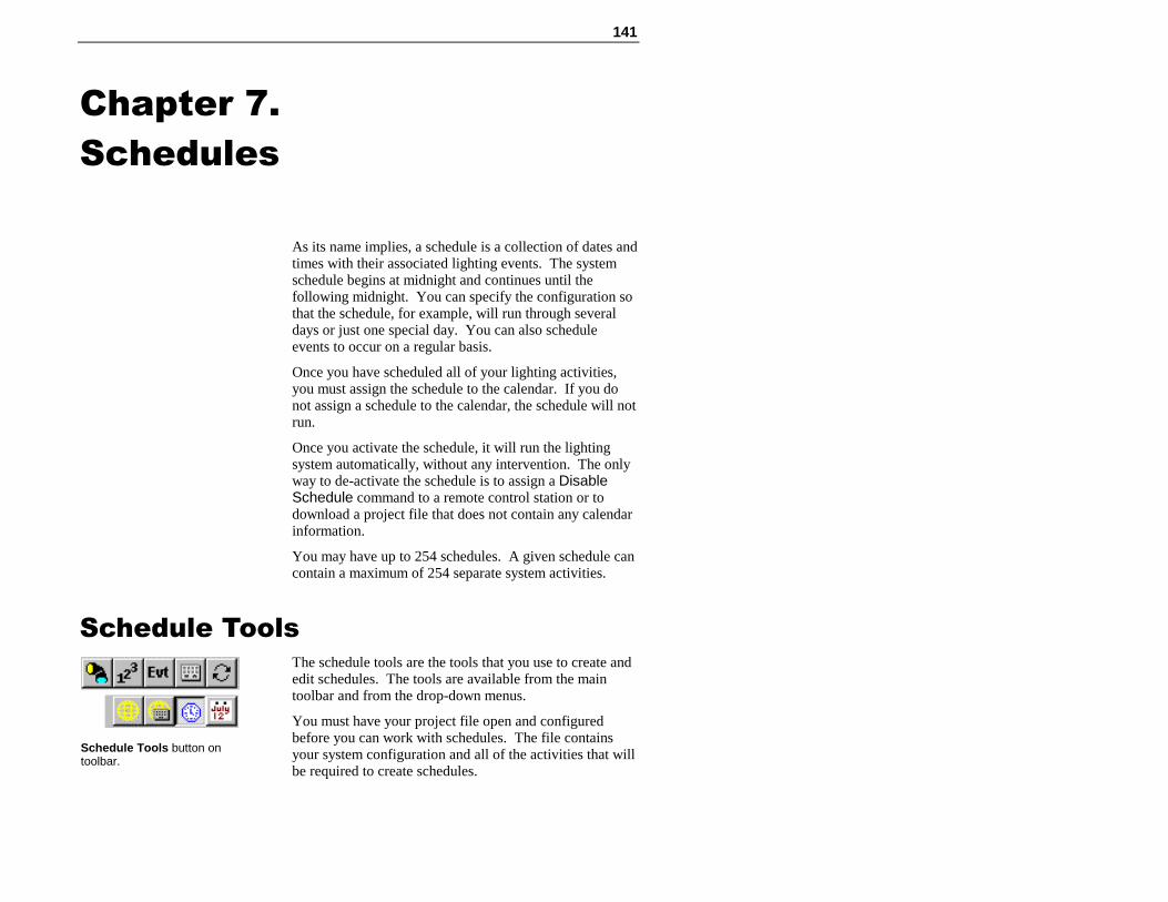
141
&KDSWHU���
6FKHGXOHV
As its name implies, a schedule is a collection of dates andtimes with their associated lighting events. The systemschedule begins at midnight and continues until thefollowing midnight. You can specify the configuration sothat the schedule, for example, will run through severaldays or just one special day. You can also scheduleevents to occur on a regular basis.
Once you have scheduled all of your lighting activities,you must assign the schedule to the calendar. If you donot assign a schedule to the calendar, the schedule will notrun.
Once you activate the schedule, it will run the lightingsystem automatically, without any intervention. The onlyway to de-activate the schedule is to assign a DisableSchedule command to a remote control station or todownload a project file that does not contain any calendarinformation.
You may have up to 254 schedules. A given schedule cancontain a maximum of 254 separate system activities.
6FKHGXOH�7RROVThe schedule tools are the tools that you use to create andedit schedules. The tools are available from the maintoolbar and from the drop-down menus.
You must have your project file open and configuredbefore you can work with schedules. The file containsyour system configuration and all of the activities that willbe required to create schedules.
Schedule Tools button ontoolbar.
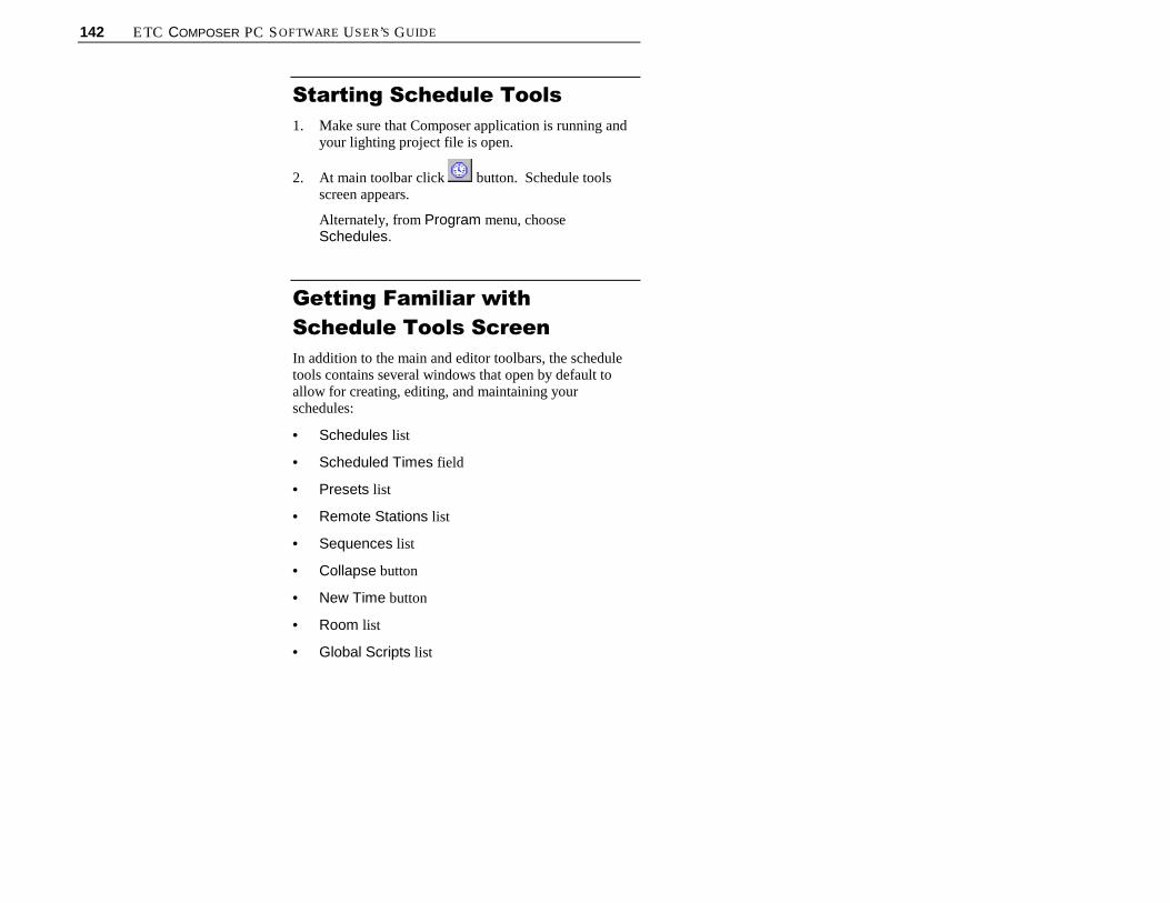
142 ETC COMPOSER PC SOFTWARE USER’S GUIDE
6WDUWLQJ�6FKHGXOH�7RROV
1. Make sure that Composer application is running andyour lighting project file is open.
2. At main toolbar click button. Schedule toolsscreen appears.
Alternately, from Program menu, chooseSchedules.
*HWWLQJ�)DPLOLDU�ZLWK
6FKHGXOH�7RROV�6FUHHQ
In addition to the main and editor toolbars, the scheduletools contains several windows that open by default toallow for creating, editing, and maintaining yourschedules:
• Schedules list
• Scheduled Times field
• Presets list
• Remote Stations list
• Sequences list
• Collapse button
• New Time button
• Room list
• Global Scripts list

CHAPTER 7. SCHEDULES 143
MainToolbar
EditorToolbar
SchedulesTimes fields
Presetslist
Sequenceslist
Global Stations list Local Stations list Schedules Global Scripts
6FKHGXOHV�/LVW
As you create new schedules you will name them,accumulating a growing list of schedules, all displayed inthe Schedules list. Once you have more schedules thanwill fit in the window, a scroll bar automatically appears.
6FKHGXOHG�7LPHV�$FWLYLWLHV�/LVW
Drag and drop preset, sequences, remote station, or globalscript commands on the schedule time for which you wantthem to begin. The default time settings are all on thehour except for the sunrise/sunset features. To view theevents assigned to a time, click on the plus (+) sign.Collapse the events for a specific time by clicking on theminus (-) sign. To schedule your event for a time that isnot displayed, click on the New Time button to create anew time. A secondary dialog appears to create the newtime.

144 ETC COMPOSER PC SOFTWARE USER’S GUIDE
6HTXHQFHV�/LVW
As you create new sequences you will name them,accumulating a growing list of sequences, all displayed inthe Sequences list. Once you have more sequences thanwill fit in the window, a scroll bar automatically appears.
3UHVHWV�/LVW
As you create new presets you will name them,accumulating a growing list of presets, all displayed in thePresets list. Once you have more presets than will fit inthe window, a scroll bar automatically appears.
*OREDO�6FULSWV�OLVW
As you create new global scripts you will name them,accumulating a growing list of scripts, all displayed in theGlobal Scripts list. Once you have more scripts than willfit in the window, a scroll bar automatically appears.
*OREDO�5HPRWH�6WDWLRQV�/LVW
As with presets and sequences, you will refer to yourglobal remote control stations by name, with the names ofconfigured stations shown in the Global RemoteStations list. Once you have more templates than will fitin the window, a scroll bar automatically appears.
/RFDO�5HPRWH�6WDWLRQV�/LVW
As with presets, sequences, and global remote stations,you will refer to your local remote control stations byname, with the names of configured stations shown in theLocal Remote Stations list. Once you have moretemplates than will fit in the window, a scroll barautomatically appears.
&ROODSVH�([SDQG�%XWWRQ
Click here to collapse or expand the Scheduled Timesevents list. The scheduled events will appear under thetime. A plus (+) sign shows you that there are eventsscheduled for that time. Click on the plus sign to expand
Expand button displaysactivities assigned toscheduled time. Click onminus (-) sign or Collapsebutton to collapse list.
Collapse button hidesactivites list. Click on plus (+)sign to view scheduledactivities assigned to a
f

CHAPTER 7. SCHEDULES 145
the list. Click on the minus sign (-) to collapse the eventsfor that time.
1HZ�7LPH�%XWWRQ
Click here to create a time that is not displayed in theScheduled Times event list. The default time settingsare all on the hour. Use the New Time dialog to create atime that is not displayed and add it to the ScheduledTimes list.
&UHDWLQJ�DQG�0DQDJLQJ�6FKHGXOHVWhenever the schedule tools are open a schedule isalways selected as the active schedule. All editingactivities apply to this selection. The rules for the activeschedule are as follows:
• The name of the active schedule is highlighted in theSchedules list.
• When you select an existing schedule (by pointingand clicking on its name) that schedule becomesactive.
• When you create a new schedule, the new schedulebecomes active.
&UHDWLQJ�1HZ�6FKHGXOH
1. Make sure that Composer application is running andthat required project file is open and in correct room.
2. Make sure that schedule tools are open.
3. Select items and drag and drop them onto ScheduledTimes activity list times. Items appear in activity listin expanded form.
4. Multiple rooms may be controlled from a singleschedule by changing active room and dragging itemsonto schedule.

146 ETC COMPOSER PC SOFTWARE USER’S GUIDE
Alternately, click on desired editor toolbar stationcommand button and complete associated dialogs.
CAUTION: Using button clears all scheduledactivities from entire schedule, not just those activitiesfrom a specific time.
4. Remove activities from activity list by clicking on
schedule item and clicking button.
Remove all activities from entire schedule by clicking
button.
5. If desired schedule time is not on hour, or you wish to
create new time, click button. NewTime dialog appears.
6. At New Time dialog data field, enter time for whichschedule event is to begin or accept default time.(Default time is current time when dialog is opened.)
7. Click on OK to add new time. Time is added toactivity list times.
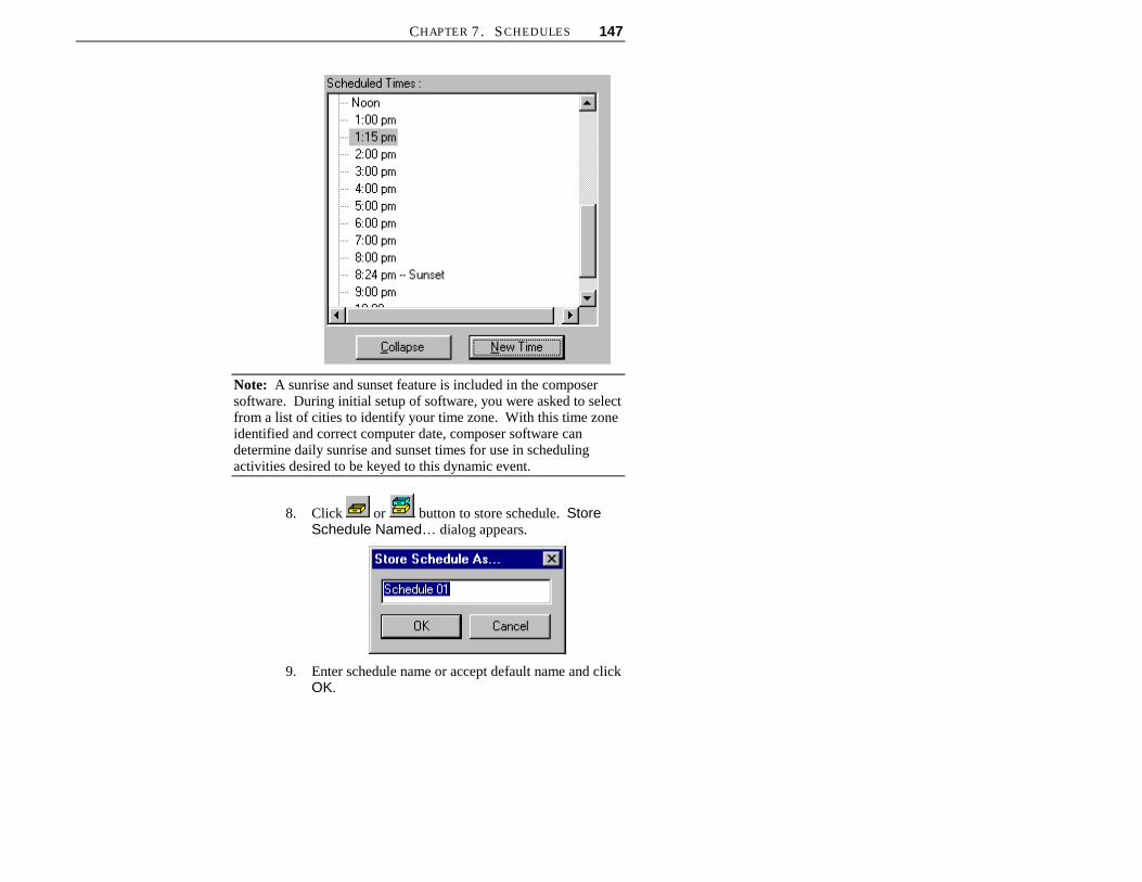
CHAPTER 7. SCHEDULES 147
Note: A sunrise and sunset feature is included in the composersoftware. During initial setup of software, you were asked to selectfrom a list of cities to identify your time zone. With this time zoneidentified and correct computer date, composer software candetermine daily sunrise and sunset times for use in schedulingactivities desired to be keyed to this dynamic event.
8. Click or button to store schedule. StoreSchedule Named… dialog appears.
9. Enter schedule name or accept default name and clickOK.

148 ETC COMPOSER PC SOFTWARE USER’S GUIDE
(GLWLQJ�([LVWLQJ�6FKHGXOH
1. Make sure that Composer application is running andthat required project file is open.
2. At main toolbar, click button to open scheduletools.
3. At Schedules list, click on schedule name to beedited to make it active. Scheduled Times activitylist appears for selected schedule.
4. Add actions by dragging and dropping or by usingeditor toolbar station command buttons.
5. Multiple rooms may be controlled from a singleschedule by changing active room and dragging itemsonto schedule. Refer to Global Templates chapter foradding Global Scripts to Schedules.
6. Remove individual activities using button and
clear all schedule assignments using button.
7. Store schedule.
a. Click button if you want to overwriteexisting schedule. Overwrite warning dialogappears.
At dialog box, click Yes to overwrite schedule.Click No to dismiss dialog and not overwriteschedule.
b. If you do not want to overwrite existing schedule,
click button to store schedule as anothername. Store Schedule As… dialog appears.

CHAPTER 7. SCHEDULES 149
Enter schedule name or accept default name andclick OK.
Note: If you attempt to select different schedule aftercreating or changing another, Store Changes warningdialog appears.
Click Yes to overwrite existing schedule. If you clickNo, overwrite warning dialog appears.
'HOHWLQJ�6FKHGXOHV
Unlike other schedule operations, to delete a schedule youhave to select it from the Schedules list. This can bedone from any Composer application screen by selectingSchedules from View menu.
1. Make sure that Composer application is running andthat required project file is open.
2. At Schedules list, select schedule to be deleted.

150 ETC COMPOSER PC SOFTWARE USER’S GUIDE
3. At main toolbar, click button. Alternately, clickright mouse button to bring up mouse popup menuand select Delete Schedule. Deletion warningdialog appears.
Click Yes to continue with delete. Click No todismiss window and not delete template.
Click button to undo schedule deletion.
$VVLJQLQJ�7HPSODWHV
Template reassignment in a schedule is an effective wayto fully utilize the Composer system’s capabilities. Whenyou assign a remote station command to the schedule youhaven’t made a physical assignment. Instead, you havescheduled the assignment for the future. When theclock/calendar is activated, the selected template will beassigned to the selected recall station at the scheduled dateand time.
Note: For other recall station commands, refer to Templatechapter.

151
&KDSWHU���
&DOHQGDU
The calendar contains schedules that can be assigned tooccur on a regular or irregular basis. The schedules aredropped onto a weekly or monthly calendar. If schedulesare not stored to the calendar, the schedules will not run.
'DLO\�5HSHDWLQJ�6FKHGXOHV
The clock/calendar subsystem within the MCP, keepstrack of the day, date and time. Because the subsystemknows whether it’s Monday, Tuesday, or any other day, itis able to look up a daily schedule associated with thecorrect day.
Daily schedules are referred to as repeating, since theyrepeat every week without any intervention orrescheduling.
You can name your repeating schedules in any way thatyou like. An obvious method is to create a schedule withthe name Monday, Tuesday, and so forth. With sevendaily schedules, you can ensure that your lighting alwaysbehaves the way you want. Some simple systems use thesame schedule for every day of the week. In this case, youcan name the schedule “lighting” and assign it to all sevendays. Similarly, you can create two schedules—onecalled “weekdays” and one called “weekends” with thegoal of managing your facility during working versusresting days.

152 ETC COMPOSER PC SOFTWARE USER’S GUIDE
6SHFLDO�'D\V�+ROLGD\V
A special schedule is one that runs on a given date asopposed to a given day. You may build a schedule called“Christmas,” for example, and then drop it onto December25. Regardless of the day of the week that it falls on, theChristmas schedule will run on Christmas Day.
����'D\�&DOHQGDU
The clock/calendar holds 365 days of scheduleinformation. The year-long calendar is a rotatingschedule, that is, new days appear in the future as old daysfall away in the past.
&DOHQGDU�7RROVThe calendar tools are the tools that you use to create andedit your system calendar, which is used to run storedschedules. The tools are available from the main toolbarand from the drop-down menus.
You must have your project file open and configuredbefore you can work with the calendar. The file containsyour system configuration and all of the schedules thatwill be required to create the calendar.
6WDUWLQJ�&DOHQGDU�7RROV
1. Make sure that Composer application is running andyour lighting project file is open.
2. At main toolbar click button. Calendar toolsscreen appears.
Alternately, from Program menu, choose Calendar.
Calendar Tools button ontoolbar.

CHAPTER 8. CALENDAR 153
*HWWLQJ�)DPLOLDU�ZLWK
&DOHQGDU�7RROV�6FUHHQ
In addition to the main toolbar, the calendar tools containstwo windows that open by default to allow for creating,editing, and maintaining your calendar:
• Schedules list
• Daily and Special Days calendars.
Schedules list Main Toolbar Daily and Special Days Calendars
6FKHGXOHV�/LVW
As you create schedules you will name them,accumulating a growing list of schedules, all displayed inthe Schedules list. Once you have more schedules thanwill fit in the window, a scroll bar automatically appears.

154 ETC COMPOSER PC SOFTWARE USER’S GUIDE
'DLO\�DQG�6SHFLDO�'D\V�&DOHQGDU
The Daily calendar represents the seven fixed days of theweek. You should assign your scheduled events thatoccur on a daily or regular basis onto this calendar. Forexample, if after business hours on every Friday you wantto turn off all of the lights, you would assign theappropriate schedule to the Friday assignment of the Dailycalendar.
The Special Days calendar is used for schedules that willoccur on a given date (as opposed to a day of the week).Special Days schedules do not repeat. When theassigned date for the schedule occurs, the schedule runs inplace of the daily repeating schedule that would normallyrun for that day of the week. A text message locatedunder the Daily calendar indicates what is assigned to theSpecial Days calendar. On that date, the specialschedule will run instead of a repeating schedule that maybe assigned to that day of the week.

CHAPTER 8. CALENDAR 155
0DQLSXODWLQJ�&DOHQGDU
You may select among days, months and years on thecalendar device by manipulating the scroll control at thebottom of the display.
Click here to displaymonth containingcurrently-selecteddate.
Click here to advanceone month forward.
Manipulate thumbcontrol to scroll frommonth to month.
Click here to displayprevious month.
Click here todisplay monthcontainingtoday’s date.
&UHDWLQJ�&DOHQGDU
1. Make sure that Composer application is running andthat required project file is open.
2. Make sure that calendar tools are open.
3. Select schedule and drag and drop it onto calendar.
a. For daily or repeating schedules, drop scheduleonto Daily calendar.
b. For singular or irregularly timed events, dropschedule onto Special Days calendar. Schedulename appears in field.
4. Drag and drop other schedules onto Daily or SpecialDays calendars. Once activities are dropped onto

156 ETC COMPOSER PC SOFTWARE USER’S GUIDE
calendar, they are automatically stored. SpecialDays calendar will display days having schedule inyellow.
5. Delete schedule from Daily calendar by highlightingschedule name and then pressing keyboard Deletekey. Delete schedule from Special Days calendar byclicking on day for which schedule is to be deletedand then pressing keyboard Delete key.
Note: Once deleted, there is no undelete feature for the calendar.
Note: There is no need to “store” the calendar data, it isautomatically stored when changes are made.
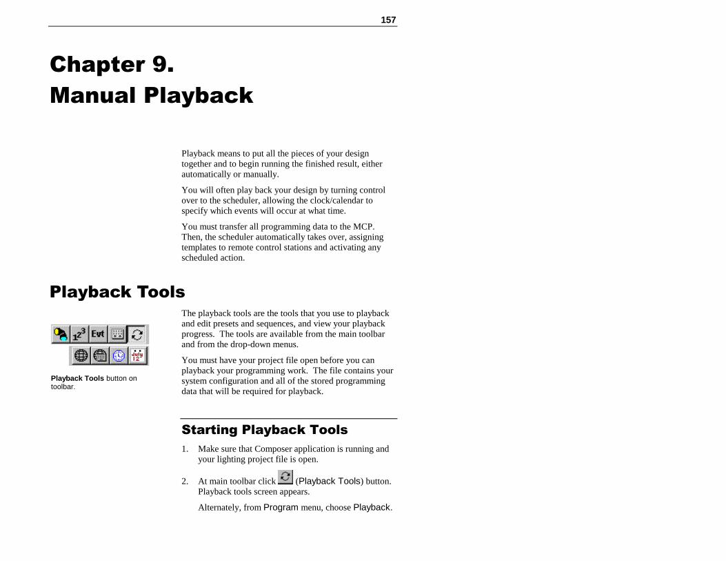
157
&KDSWHU���
0DQXDO�3OD\EDFN
Playback means to put all the pieces of your designtogether and to begin running the finished result, eitherautomatically or manually.
You will often play back your design by turning controlover to the scheduler, allowing the clock/calendar tospecify which events will occur at what time.
You must transfer all programming data to the MCP.Then, the scheduler automatically takes over, assigningtemplates to remote control stations and activating anyscheduled action.
3OD\EDFN�7RROVThe playback tools are the tools that you use to playbackand edit presets and sequences, and view your playbackprogress. The tools are available from the main toolbarand from the drop-down menus.
You must have your project file open before you canplayback your programming work. The file contains yoursystem configuration and all of the stored programmingdata that will be required for playback.
6WDUWLQJ�3OD\EDFN�7RROV
1. Make sure that Composer application is running andyour lighting project file is open.
2. At main toolbar click (Playback Tools) button.Playback tools screen appears.
Alternately, from Program menu, choose Playback.
Playback Tools button ontoolbar.

158 ETC COMPOSER PC SOFTWARE USER’S GUIDE
*HWWLQJ�)DPLOLDU�ZLWK
3OD\EDFN�7RROV�6FUHHQ
In addition to the main and playback toolbars, theplayback tools contain windows that open by default toallow for playing back presets and sequences:
• Presets list
• Grid
• Playback Activity window
• Sequences list.
Preset list Main Toolbar Editor Toolbar Grid
Sequences list Playback Activity window

CHAPTER 9. MANUAL PLAYBACK 159
3UHVHWV�/LVW
As you create new presets you will name them,accumulating a growing list of presets, all displayed in thePresets list. Once you have more presets than will fit inthe window, a scroll bar automatically appears.
*ULG
The grid is a spreadsheet-like device that displays all ofyour programming data.
The programming data are listed at the top of the columnsand the luminaire names and their parameter values aredisplayed on the left. Clicking on the cells of thespreadsheet allows you to edit the data in the cells withouthaving to use the preset tools.
6HTXHQFHV�/LVW
As you create new sequences you will name them,accumulating a growing list of sequences, all displayed inthe Sequences list. Once you have more sequences thanwill fit in the window, a scroll bar automatically appears.
160 ETC COMPOSER PC SOFTWARE USER’S GUIDE
(This page intentionally blank)

CHAPTER 9. MANUAL PLAYBACK 161
3UHVHW�DQG�6HTXHQFH�3OD\EDFNPlayback is important not only for lighting, but also fortesting. In general, it is important to fully test yoursystem, both with and without timing enabled, to makesure that the system and your luminaires are performing asanticipated.
The playback toolbar contains the playback buttons.
The first two buttons are used to playback a preset and asequence, respectively. The other buttons are used toreset the sequence to the first preset, step backward, stepforward and to advance to the last item, respectively.
It is important to remember that when you playback apreset or sequence that you also playback the timingvalues stored with the event. You can turn off the timingfor playback, which can be especially useful when test andchecking out your programming data.
You use the (Activate Timing) button to turn timingon and off. When timing is turned off, the lightingparameters move to their end state as quickly as possible.For sequences, this means that presets can be stepped asquickly as it takes for the luminaires to achieve their end
state. The default state for the button is with timingenabled. You have to click it one time to disable timing.
3UHVHW�3OD\EDFN
When you playback a preset, the other playback buttonsallow you to scroll through and play back your presets.When used to step through the playback of a sequence, the
(Step Forward) button would step to the next preset
in the sequence. When you playback a preset, the button plays back the following preset from the Presetslist.

162 ETC COMPOSER PC SOFTWARE USER’S GUIDE
To playback preset:
1. Make sure that Composer software is running and thatrequired project file is open.
2. Make sure that playback tools are open.
3. At Presets list, click on preset to playback to make itactive.
Note: When you playback a preset, all timing values willalso be played back. For presets with long timing values,playback could take a very long time.
4. If preset is to be played back without timing, at
playback toolbar, click button.
5. At playback toolbar, click on (Playback Preset)button to playback preset. Progress of preset isdisplayed in Playback Activity window.
6HTXHQFH�3OD\EDFN
When you playback a sequence, you can play back thesequence with full timing and follow times, or you canstop automatic playback and begin manually steppingthrough the sequence a preset at a time.
To play back sequence:
1. Make sure that Composer software is running and thatrequired project file is open.
2. Make sure that playback tools are open.
3. At Sequences list, click on sequence to playback tomake it active.
Note: When you playback a sequence, all timing valueswill also be played back. For sequences with long timingvalues, playback could take very long time.

CHAPTER 9. MANUAL PLAYBACK 163
4. If sequence is to be played back without timing, at
playback toolbar, click button.
5. At playback toolbar, click on (PlaybackSequence) button to playback sequence. Progressof sequence is displayed in Playback Activitywindow.
To step through sequence, click (Stop) button
and then click (Step Forward) and (StepBack) buttons.
To advance to the end state of sequence, click (Go to the Last Item) button.
To reset sequence to first preset, click (Go tothe First Item) button.
Edit sequence as needed as you step through it usingsequence tools.
6\QFKURQL]LQJ�/LJKWLQJ�'HYLFHVThere may be times that your lighting system is operatingon MCP data and not data from the Composer softwarerunning at the PC. This situation could occur, forinstance, if a recall station button is pushed. When therecall station button is pushed, the MCP activates theaction assigned to that button push. That lighting actionmost likely will not be what is currently running at the PC.
The easiest way to get your lighting system running fromthe PC accurately is to synchronize the luminaires. You
use the playback toolbar (Synchronize) button tosynchronize the selected luminaires. When you push the
164 ETC COMPOSER PC SOFTWARE USER’S GUIDE
button, the Composer software selects all lightingdevices in your room and then sends to them the currentlighting parameter values displayed on the PC. This couldbe a specific preset’s settings that may be active, or itcould be an interim lighting look that you were working
on when you clicked on the button.
The easiest way to avoid having your lighting systemmove to an authorized or untimely schedule event is tolock out all input to the MCP. This will allow you toprogram or edit your project file from the PC withouthaving a remote control station command or button pushchange the lighting parameters you are setting at the PC.You can lock out all data input to the MCP (lock allcommunication from remote control stations and
schedule) by clicking on the (Lockout) button.
To synchronize luminaires:
1. Make sure that Composer application is running andthat required project file and desired room are bothopen.
2. At playback toolbar, click on button. Allluminaires will move to parameter values displayed ingrid.
Note: All luminaires in a room will be synchronized
when button is clicked, not just selected or movingluminaires.
To lockout lighting system changes:
1. Make sure that Composer application is running andthat required project file is open and correct roomselected.
2. At playback toolbar, click on button. Composersystem will now only allow data input from PCstation.

CHAPTER 9. MANUAL PLAYBACK 165
6WDUWLQJ�'LVDEOLQJ�6FKHGXOHUWhen you download your room file to the MCP, yourcalendar schedules will begin to run automatically.
When active, the clock/calendar automatically triggerslighting events as they are scheduled. For as long as youhave a schedule assigned to a calendar loaded in the MCP,the schedule will run. A Disable Schedule commandshould be assigned to a remote control station. Use of thiscommand is the only way to stop a schedule once it isrunning.
Refer to chapter on Data Transfers and Backups for theprocedure to download your project file to the MCP.

166 ETC COMPOSER PC SOFTWARE USER’S GUIDE
(This page intentionally blank)
167
&KDSWHU����
'DWD�7UDQVIHUV�DQG�%DFNXSV
There are several Composer software system operations,including transferring data to and from the MCP andbacking up your project files.
After your lighting project file is complete, you mustdownload your file to the MCP. The scheduler willautomatically begin running, and continue to rununinterruptedly.
0&3�'DWD�7UDQVIHU�2SHUDWLRQVThere are several MCP operations that are activated fromthe Composer software:
• Download programming data to MCP.
• Retrieving data from MCP.
• Setting MCP clock/calendar from PC.
'RZQORDGLQJ�3URJUDPPLQJ
'DWD�WR�0&3
You must transfer your programming data to the MCP toinitiate playback. Your MCP must possess its operatingsoftware, as well as the configuration and programmingdata that you develop, for playback. You may also wishto ensure that the date and time are set correctly, and tovalidate the behavior of your remote control stations.
As soon as all programming data have been transferred,the MCP automatically starts its schedule and waits for thefirst scheduled activity according to the current date andtime.

168 ETC COMPOSER PC SOFTWARE USER’S GUIDE
There is no need to explicitly start the MCP system. Assoon as all data are transferred successfully, you maydisconnect the PC.
To transfer data to MCP:
1. Make sure that Composer application is running andyour lighting project file is open.
2. At System menu, choose MCP Update. Then selectProgramming Data from drop-down menu.Transfer Data dialog appears.
3. Click on button to begin data transferprocess. The data transfer progress bar dialogappears.
Note: You may stop transfer of data to MCP at any time
by clicking button.
4. When data transfer is complete, transfer completedialog appears.
5. When transfer has finished successfully, click on OK.

169
Tip: Transfer time will vary depending on size of file. Ifyour communications link is noisy, transfer may beslower. If transfer is very slow or appears to stopaltogether, there may be something wrong with your dataconnection. Abort transfer and locate problem beforeproceeding.

170 ETC COMPOSER PC SOFTWARE USER’S GUIDE
5HWULHYLQJ�'DWD�)URP�0&3
A project file can be retrieved from the MCP. Thistransaction is useful, for instance, if you have theComposer software loaded on more than one PC and wantto download a project file to the other PCs. Once the datatransfer is complete, the project file can be edited and re-stored to the MCP.
To retrieve data from the MCP:
Note: Project file does not have to be open to updateMCP time/date or retrieve MCP data.
1. Make sure that Composer application is running.
2. At System menu, choose Retrieve MCP Data…Retrieve Data from MCP and Save As… dialogappears.
3. Select appropriate directory and file name.
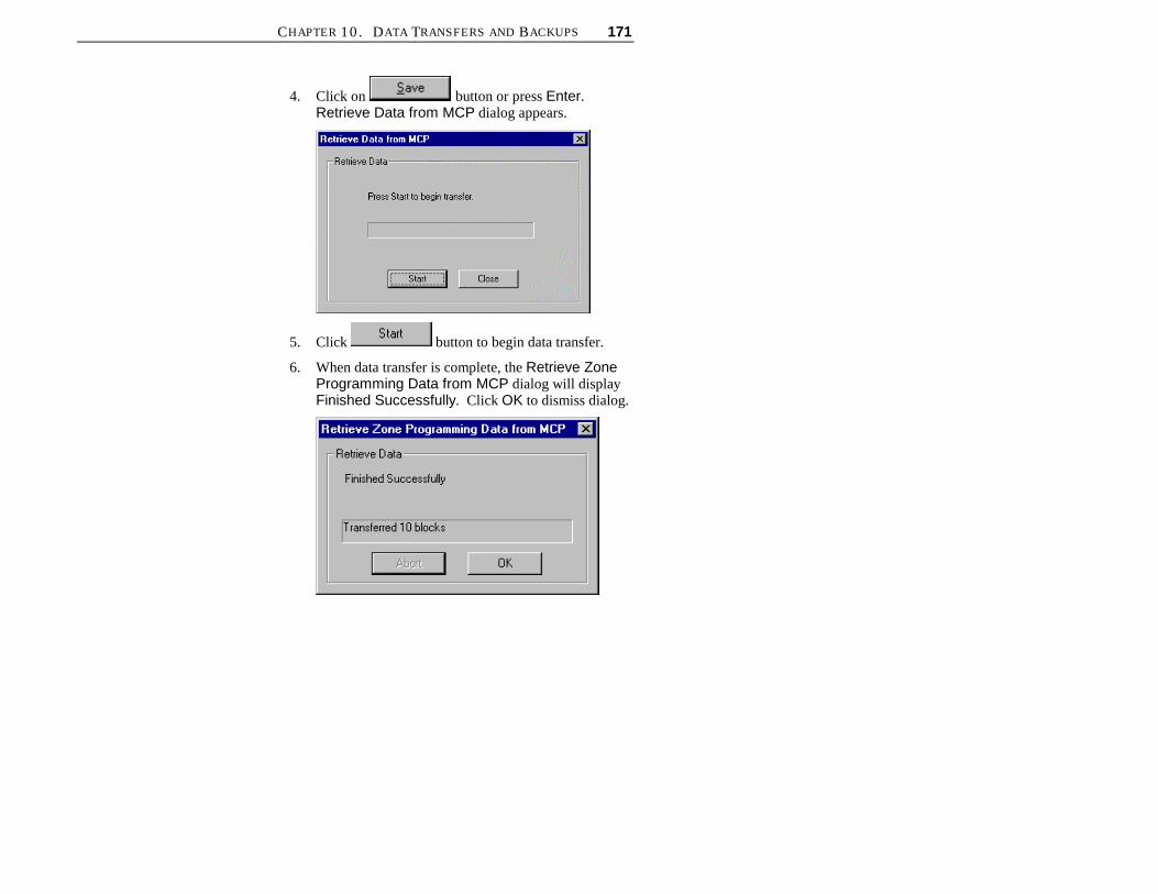
CHAPTER 10. DATA TRANSFERS AND BACKUPS 171
4. Click on button or press Enter.Retrieve Data from MCP dialog appears.
5. Click button to begin data transfer.
6. When data transfer is complete, the Retrieve ZoneProgramming Data from MCP dialog will displayFinished Successfully. Click OK to dismiss dialog.

172 ETC COMPOSER PC SOFTWARE USER’S GUIDE
6HWWLQJ�&ORFN�&DOHQGDU�)URP�3&It is important that the MCP know the correct date andtime. You can set the MCP clock/calendar directly fromyour PC at any time.
To set clock/calendar from PC:
1. Make sure that Composer application is running.
2. At System menu, choose MCP Update. Then selectTime/Date from drop-down menu. MCP isimmediately updated. There will no confirmationdisplayed at PC.
3. At MCP front panel LCD, verify that time/date hasupdated to that of your PC.
%DFNLQJ�8S�3URMHFW�)LOHVAlthough the Composer software saves your projectchanges on-the-fly, the system does not create a backupcopy. In case of a malfunction of your PC (for example, asudden loss of power or other graceless exit), you shouldkeep a backup copy of the show file on another PC or on a3.5” floppy diskette.
1. From the File menu, choose Save As. Save Asdialog appears.
2. Navigate to drive where you want to store file (orselect floppy diskette drive; usually A: drive) andassign name for file or accept default name.
3. Click Save to save file.
Be sure to periodically copyroom files from hard disk tofloppy diskette to ensure thatyou have backup copy in caseof data loss or hard diskfailure.

CHAPTER 10. DATA TRANSFERS AND BACKUPS 173
3&�6KXWGRZQ�DQG�'LVFRQQHFWOnce you have programmed your lighting system and aresatisfied with its performance, you can disconnect yourPC if you are using an MCP system.
To shut down and disconnect PC:
Note: Be sure to copy your project file to a backupdiskette to protect against data loss or corruption.
1. If Composer application is running with an openproject file, at File menu, select Close.
Alternately, you can click on button to close file.
2. At main Composer application screen, at File menu,select Exit.
Alternately, you can click on button to exitComposer application.
3. At wall-mounted programming receptacle remotecontrol station, disconnect serial connector.
4. At PC, disconnect other end of serial cable.
5. At Windows 95 taskbar, click button andchoose Shut Down…
6. When shut down is complete, remove power to PC.

174 ETC COMPOSER PC SOFTWARE USER’S GUIDE
(This page intentionally blank)

CHAPTER 10. DATA TRANSFERS AND BACKUPS 175
(This page intentionally blank)

176 ETC COMPOSER PC SOFTWARE USER’S GUIDE
(This page intentionally blank)