Embed Size (px)
Citation preview

Version 10
Interface Guide
Revision 1.05

Interface Guide
Page 2 of 228

Interface Guide
Page 3 of 228
Copyright notice © Copyright 1982-2017. Magi-Cut Software Ltd. All rights reserved No part of this document may be reproduced or transmitted in any form or by any means, electronic or mechanical, for any purpose, without the express written permission of Magi-Cut Software Ltd. Notices & Acknowledgements Microsoft, MS-DOS, Visual Basic, Windows, Windows NT, Windows Vista, Windows 7 , Windows 8, Windows 10 are either registered trademarks or trademarks of the Microsoft Corporation. Several of the diagrams in this manual are based on images provided by the Corel Corporation and the Microsoft Corporation.

Interface Guide
Page 4 of 228
Contents 1. Introduction ...................................................................................................................... 5
1.1 Overview of the program ............................................................................................ 7 1.2 Nested Optimising .................................................................................................... 21
2. Import data..................................................................................................................... 28 2.1 Import parts .............................................................................................................. 30 2.2 Import product requirements .................................................................................... 55 2.3 Import boards ........................................................................................................... 69 2.4 Import Parts / Boards / Patterns - Pattern Exchange Format (PTX) ........................ 83 2.5 Import/Export DXF drawings for Patterns and Parts ................................................ 93 2.6 External drawings - Part library and Product library ................................................. 99 2.7 Import from file - part library ................................................................................... 101 2.8 Import product data ................................................................................................ 103
3. Pattern Exchange File - Specification - V1.14 ............................................................. 110 4. Export data .................................................................................................................. 155
4.1 Export runs ............................................................................................................. 155 4.2 Export Part and Product costing reports ................................................................ 162 4.3 Export fittings and operations................................................................................. 164 4.4 Export cutting lists .................................................................................................. 165 4.5 Export - Pattern Exchange Format ........................................................................ 168 4.6 Export - Board library data ..................................................................................... 172 4.7 Export - Part library data ........................................................................................ 173 4.8 Export - Product data ............................................................................................. 174 4.9 Export variables deployment list ............................................................................ 179
5. Stand alone operation .................................................................................................. 182 5.1 Import parts / boards / patterns - stand alone ........................................................ 182 5.2 Export reports - stand alone ................................................................................... 186 5.3 Export Library data - stand alone .......................................................................... 190 5.4 Batch operations - stand alone .............................................................................. 191 5.5 Stock update and stock issue - stand alone .......................................................... 193 5.6 Import product requirements - stand alone ............................................................ 199 5.7 Saw transfer - stand alone ..................................................................................... 201 5.9 Stand alone operation - examples ......................................................................... 204 5.10 CadLink program ................................................................................................. 206
6. Useful system and other parameters ........................................................................... 215

Interface Guide
Page 5 of 228
Welcome to the Version 10 Interface Guide
1. Introduction This guide describes how to import and export data to and from the V10 Optimising and Production software. It gives the details for interfacing with the program and extracting data from the system
What does V10 do? V10 is a comprehensive software package that covers most aspects of optimisation and production for the Furniture, Woodworking, and other Sheet processing industries. It is Windows software which runs on most computers. It provides all the information to keep control of costs, cut down errors, and cut material efficiently and effectively. V10 deals with a variety of products. • Kitchen cabinets • Office furniture • Shop fittings • Doors • Plastic fabrications • Caravans • Bathrooms • Vanity Units Enter or import part sizes and quantities and let the pro gram create a set of cutting patterns and cutting instructions. From the cutting patterns send information directly to the saw or machining centre to cut each pattern and machine each part. The program works in Millimetres, Decimal Inches, or Fractional (Imperial) inches. Part lists can be entered in any measurement and converted.

Interface Guide
Page 6 of 228
The basic steps are:-
• Create or Import a list of part sizes • Optimise • Review cutting patterns • Send cutting data to the saw Why do I need this Interface guide ? This guide is NOT required for everyday operation Use this guide to integrate the Optimising program with other computer operations. Some typical situations are listed below. Import parts lists or product requirements lists - part lists or lists of product requirements may be stored on another database / system and need to be transferred to the Optimising software ready for optimisation. Export results for further analysis - export the summary results of each optimisation to another database or spread sheet for further analysis. Stand alone operation - run a sub-set of the Optimising software. For example, one customer enters lists of parts to be cut at remote sites using a text editor and transfers the results to a central location to be optimised. Interfacing with special machinery- to export data in a special format so that it can be used by other machinery. e.g. specialist loading or destacking equipment. Interfacing with saws and machine centres not covered by the software - the Optimising software covers a wide range of saws and machining centres but it may be

Interface Guide
Page 7 of 228
necessary to do extra work to link to specialist machines or machines not covered by the standard software. 1.1 Overview of the program Start at the main screen, this is the command centre of the system. Access all the options from here.
Main screen The program name is shown at the top of the screen. There are different names in some countries, for example, Cut-Rite, Magi-Cut, Schnitt-Profi(t) … At the left is a tree showing the various options and existing data. Click on an item in the tree to see the files in a category. There are also traditional menus and buttons to access all the options.
Interface Guide
Page 8 of 228
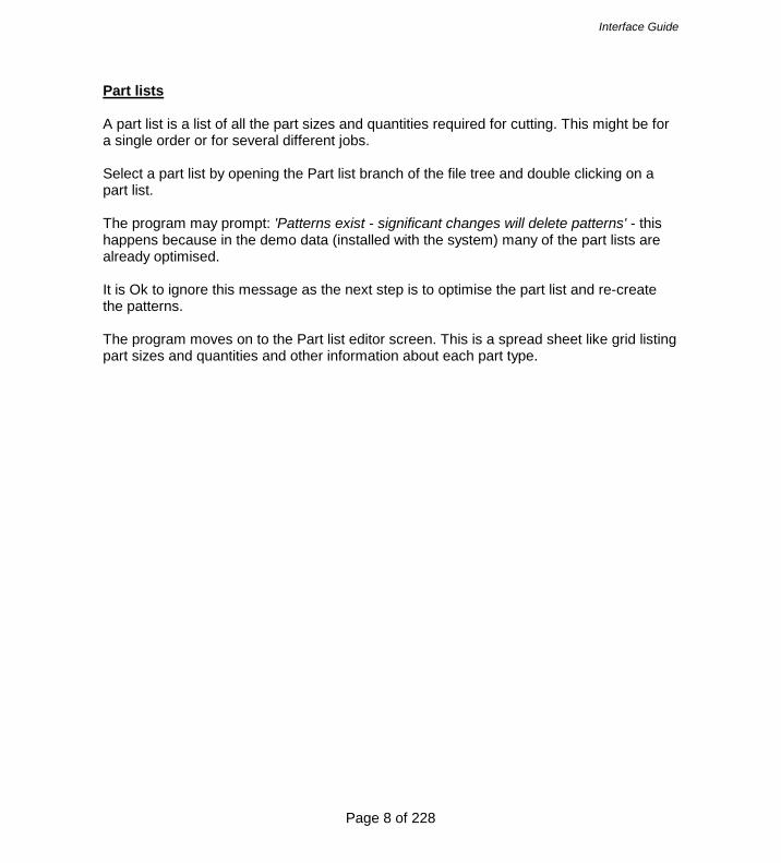
Part lists A part list is a list of all the part sizes and quantities required for cutting. This might be for a single order or for several different jobs. Select a part list by opening the Part list branch of the file tree and double clicking on a part list. The program may prompt: 'Patterns exist - significant changes will delete patterns' - this happens because in the demo data (installed with the system) many of the part lists are already optimised. It is Ok to ignore this message as the next step is to optimise the part list and re-create the patterns. The program moves on to the Part list editor screen. This is a spread sheet like grid listing part sizes and quantities and other information about each part type.
Interface Guide
Page 9 of 228
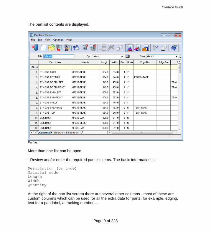
The part list contents are displayed.
Part list More than one list can be open. - Review and/or enter the required part list items. The basic information is:- Description (or code) Material code Length Width Quantity At the right of the part list screen there are several other columns - most of these are custom columns which can be used for all the extra data for parts, for example, edging, text for a part label, a tracking number …

Interface Guide
Page 10 of 228
MATERIAL CODE: This is important because it determines the material for a part. The program uses this to extract candidate boards from the board library and create a board list. The board list is simply the list of available board sizes and quantities for the job. The program also supports fractional inches and decimal inches.
Part list - fractional inches

Interface Guide
Page 11 of 228
Board list
Click on the toolbar symbol to view the Board list
Board list The Board list is created by the program extracting from the Board library all board sizes (and offcuts if any) matching the material codes used in the Part list against each part. Board can include full size stock boards and offcuts from previous runs (marked with a type of ‘X’.

Interface Guide
Page 12 of 228
Board library The board library stores the details and quantities of all the sheet material (a library is provided in the demo data).
Board library In this example there are two board sizes available for material MFC18-BEECH and several offcuts. The board library can include extra information for each sheet size, for example, cost, how to deal with low stock levels, storage ... Note - There are a wide range of materials from different suppliers so before using the program for real - an important task is to set up the board library for the materials typically available for the company.

Interface Guide
Page 13 of 228
The Board library also supports decimal and fractional inches.
Board library - fractional inches Optimise Once the Part list and Board list are created the job is ready to be optimised. At the Part list screen (or at the Board list screen):-
Select the optimise symbol The program produces a set of cutting patterns and moves to the 'Review runs' section of the program. This shows all cutting patterns and a set of summary reports.

Interface Guide
Page 14 of 228
The first report shown is an overall summary of the job; the Management Summary.
Management summary This is an overall summary of the job, for example. Total costs, Overall Waste percentage, Net material used … Use the Navigation buttons or 'Summaries' menu option to view other reports.

Interface Guide
Page 15 of 228
At the foot of the report are a set of tabs with more information. For example, the 'Dashboard' gives a graphical view of the data.
Dashboard
Interface Guide
Page 16 of 228
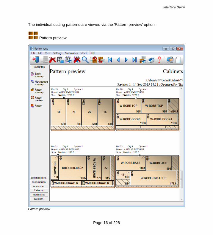
The individual cutting patterns are viewed via the 'Pattern preview' option.
Pattern preview
Pattern preview
Interface Guide
Page 17 of 228
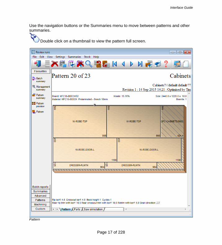
Use the navigation buttons or the Summaries menu to move between patterns and other summaries.
Double click on a thumbnail to view the pattern full screen.
Pattern
Interface Guide
Page 18 of 228
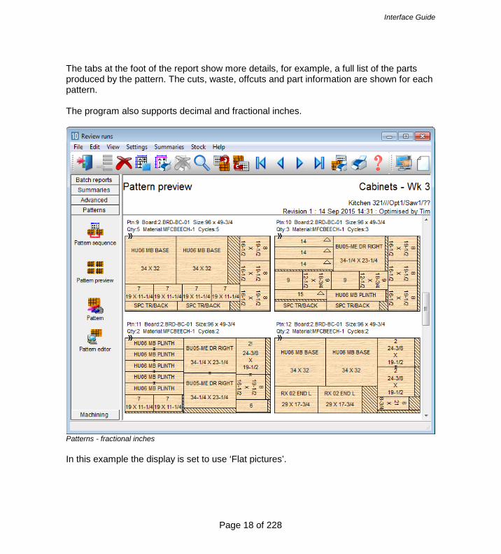
The tabs at the foot of the report show more details, for example, a full list of the parts produced by the pattern. The cuts, waste, offcuts and part information are shown for each pattern. The program also supports decimal and fractional inches.
Patterns - fractional inches In this example the display is set to use ‘Flat pictures’.

Interface Guide
Page 19 of 228
Transfer to Saw or Machining centre After Optimisation the patterns (cutting instructions) are transferred to the Saw or Machining centre.
The program supports a wide range of saw controllers:-
Cadmatic (all types) Compumatic Topmatic Homag Sawtech (CHxx, NPS400, Ilenia) Table saws Online PC Various other controllers Printed patterns and cutting instructions for manual saws
Some of the Machining centre transfer options are:-
2D DXF non-layered (DXF) Busellato Autolink (DXF) Weeke WoodWop V2.5 (MPR) 2D DXF layered (DXF) Biesse RoverCAD (CID) Morbidelli Aspan V3.2 (ASC) Morbidelli Aspan V4.0 (ASC) 3D DXF layered (DXF) Weeke WoodWop V4/V5/V6/V7 (MPR(X)) 2D DXF nested layered (DXF) 2D DXF Biesse layered (DXF) ASCII/Unicode (PTX) MDB (PTX)
At the main screen select the Saw transfer or Machining Interface option.
Saw Transfer Machining interface

Interface Guide
Page 20 of 228
For Saw transfer, for example, the program prompts with the current job.
Transfer to saw batch screen
Select the 'Continue' option

Interface Guide
Page 21 of 228
The program displays the data to transfer.
Transfer to Saw - OK to confirm The transfer is finished. Note - For practical use the saw transfer and machining transfer need to be set up for the company's machines. There are parameters for this and a wide range of options are available. Typically the saw or machining centre transfer sends data to a location on the Network (Path for Saw data) and a separate program provided by the machinery manufacturer runs and sends the data to the machine. 1.2 Nested Optimising The program also provides Nested optimising - in this case the transfer is usually to a Machine centre to both divide the patterns and machine the parts. The Nested optimiser deals with Rectangular and Shaped parts.

Interface Guide
Page 22 of 228
Import and Export operate in the same way for Optimising and Nested Optimising and the program operations and reports are the same, for example, the Management summary.

Interface Guide
Page 23 of 228
The runs are typically based on rectangular and shaped parts and are usually for smaller run quantities, processed one high.

Interface Guide
Page 24 of 228
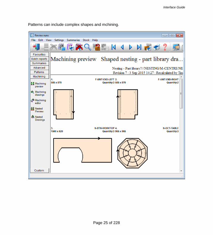
The pattern contains the cutting instructions for the pattern and the machining for each part.
Interface Guide
Page 25 of 228
Patterns can include complex shapes and mchining.

Interface Guide
Page 26 of 228
The nesting option can be used and integrated with Weeke WoodWop and MPR(X) files.

Interface Guide
Page 27 of 228
In this example the patterns are based on MPR(X) drawings.
Note - When dealing with MPR(X) parts import can be a bit tricky as it has to take account of the variables in the MPR(X) files.
Interface Guide
Page 28 of 228
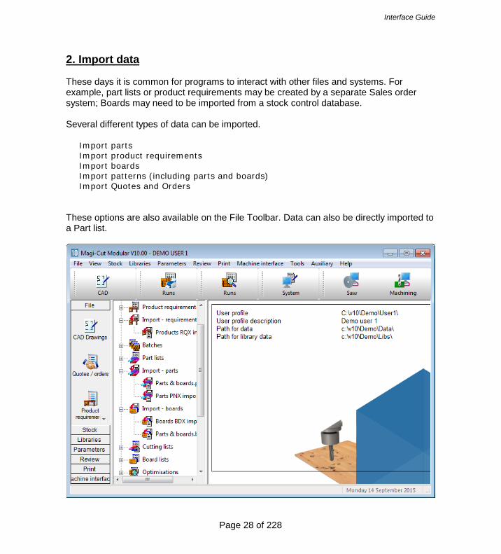
2. Import data These days it is common for programs to interact with other files and systems. For example, part lists or product requirements may be created by a separate Sales order system; Boards may need to be imported from a stock control database. Several different types of data can be imported.
Import parts Import product requirements Import boards Import patterns (including parts and boards) Import Quotes and Orders
These options are also available on the File Toolbar. Data can also be directly imported to a Part list.

Interface Guide
Page 29 of 228
Import options Most common is to import parts lists created by another system, for example, an order or sales system. When working with products it is quite likely the product requirements are generated by an external sales system. For boards is it sometimes necessary to import boards to the board library (the Stock control module is required for this). The system can also be set up to synchronise with external board databases e.g. Bargstedt SQL. Sometimes users with one-off jobs with special board sizes prefer to import the board list rather than add those items to the board library.

Interface Guide
Page 30 of 228
2.1 Import parts Import parts - operation Part lists can be quickly imported. At the main menu there are direct options on the File menu.
Import parts

Interface Guide
Page 31 of 228
The program moves to the Import screen.
Import parts - Select a file to import
Interface Guide
Page 32 of 228
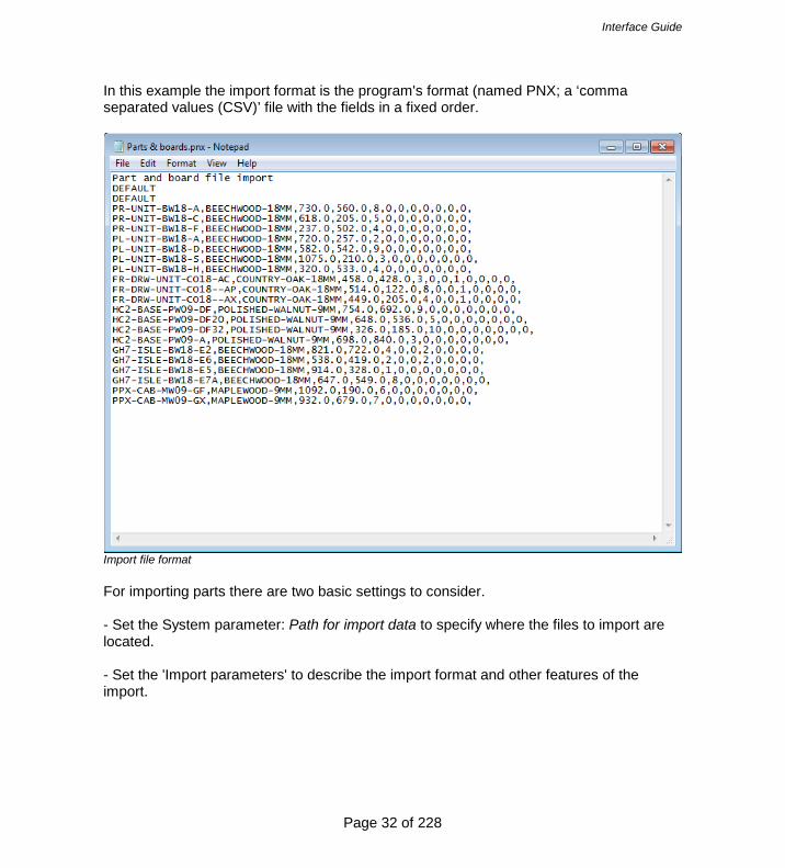
In this example the import format is the program's format (named PNX; a ‘comma separated values (CSV)’ file with the fields in a fixed order.
Import file format For importing parts there are two basic settings to consider. - Set the System parameter: Path for import data to specify where the files to import are located. - Set the 'Import parameters' to describe the import format and other features of the import.
Interface Guide
Page 33 of 228
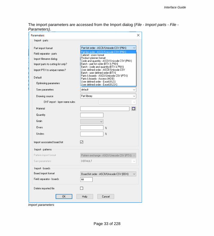
The import parameters are accessed from the Import dialog (File - Import parts - File - Parameters).
Import parameters

Interface Guide
Page 34 of 228
One of the simplest options is: Part list order – ASCII/Unicode CSV (PNX) The standard format is PNX but there are several other formats to choose from. Some are more complex imports where part and board sizes can be imported in one go or a batch of part lists can be imported, for example, 'Batch, part list order'. The options are:-
Part list order – ASCII/Unicode CSV (PNX) Cabinet Vision format Product Planner format Code and quantity – ASCII/Unicode CSV (PNX) Batch - part list order (BTX & PNX) Batch - Code and quantity (BTX & PNX) User defined order – ASCII/Unicode CSV Batch - user defined order (BTX) Parts & boards – ASCII/Unicode CSV (PTX) Parts & boards - Access (MDB) User defined order (XLS) User defined order (XLXS)
There are several other parameters to control the import of parts, for example, to set the separator character and to set whether the import files are deleted after import … Custom import formats - It is also possible to use a custom format (user defined format). This can be useful where there is limited control over the format of the external file (see: Part list import parameters'). Once the format is set files can be quickly imported from the File tree at the main screen.

Interface Guide
Page 35 of 228
Import data at the Part list At the part list data can be imported directly (File – Import)

Interface Guide
Page 36 of 228
Where the format of the external file is not known or needs to be set up – use the Import Wizard (File – Import Wizard).
The program imports data from any CSV (comma separated values) files and Excel files.

Interface Guide
Page 37 of 228
You can then work through the fields and assign them to the correct Part list fields name by selecting the field name on the ‘What’s this’ button.
Note – you can also cut and paste directly from a spreadsheet to the part list – for example where the spreadsheet has data in the same order and format as the part list.

Interface Guide
Page 38 of 228
Part list details A part list is a list of part sizes and quantities to cut. 'Import parts' is the process of importing a list of sizes and quantities. The parts can then be optimised to produce cutting patterns. A simple import file:-
This is the basic data for a part: Part code, Material code, Length, Width, Quantity with the fields in the same order as displayed at the part list screen. This format (called PNX) is automatically recognised by the Optimising software - use this format if possible. The import file extension is PNX e.g. JOB1.PNX
Interface Guide
Page 39 of 228
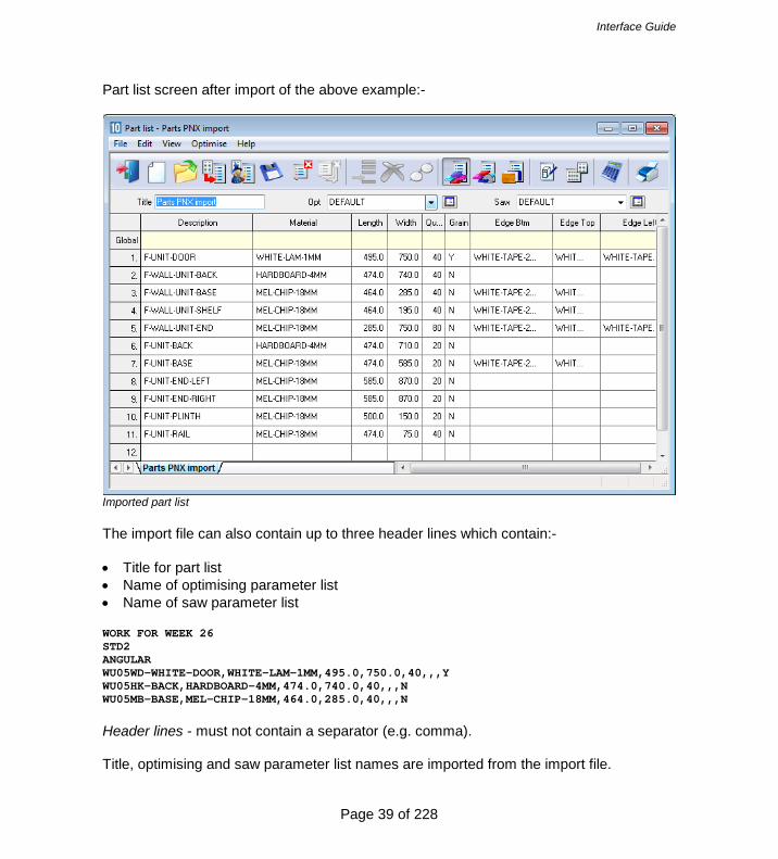
Part list screen after import of the above example:-
Imported part list The import file can also contain up to three header lines which contain:- • Title for part list • Name of optimising parameter list • Name of saw parameter list WORK FOR WEEK 26 STD2 ANGULAR WU05WD-WHITE-DOOR,WHITE-LAM-1MM,495.0,750.0,40,,,Y WU05HK-BACK,HARDBOARD-4MM,474.0,740.0,40,,,N WU05MB-BASE,MEL-CHIP-18MM,464.0,285.0,40,,,N Header lines - must not contain a separator (e.g. comma). Title, optimising and saw parameter list names are imported from the import file.

Interface Guide
Page 40 of 228
Part list data A part list is essentially a list of part sizes, quantities and the material to use for each part.
Part list The basic part list data is described below. Part list title - a description for the part list. Use this to identify part lists - the title is shown on most screens and printed on most reports. Optimising parameter list name - parameter list to use when optimising a part list. The optimising parameter list describes features such as the saw kerf, trims, and type of recuts to use when optimising.
Interface Guide
Page 41 of 228
Saw parameter list name - name of the saw parameter list to use when optimising a part list. Saw parameters describe the features of a saw, such as, overall cutting length, minimum trims, method of re-cutting etc. Optimising and saw parameter names default - optimising and saw parameter names are automatically defaulted to the first entry in the list of parameters files if they are not otherwise specified. Part description - a description or code for each part. Material - a unique material code. For example, 15mm melamine faced chipboard could have a code like MFC15 or 3/4 inch particle board might be PB3/4. The materials are stored in the Board library. There is a material code against each part in the part list so that the program uses the correct boards for each part. Part sizes - The part sizes are the Length and Width of the part. The length is usually the longest edge of the part and if the part is grained the length is the dimension running along the grain direction. The width is usually the shortest edge of the part but if the material is grained the width is the dimension running across the grain direction. The order in which the length and width columns are displayed depends on the setting of the System parameter: Order of dimensions for parts. If possible keep the order of length and width fields in the import file the same as that set in the system parameters. In the program the 'length' and 'width' are the dimensions set by the 'length' and 'width' fields regardless of the relative sizes of the dimensions. Part quantity - quantity required Over/under production - allowed under or over production of a part. If they are set for each part they represent the absolute number of over or under produced parts. If they are set in the global header line they represent the percentage of over or under produced parts for every part in the list. Grain - parts - describes the grain of the part. Y - Grain runs along length X - Grain runs along width N - No grain In an import file the grain value is represented by a number '0' - no grain, '1' grain along length, '2' grain along width.
Interface Guide
Page 42 of 228
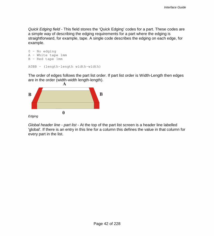
Quick Edging field - This field stores the ‘Quick Edging’ codes for a part. These codes are a simple way of describing the edging requirements for a part where the edging is straightforward, for example, tape. A single code describes the edging on each edge, for example. 0 - No edging A - White tape 1mm B - Red tape 1mm A0BB - (length-length width-width) The order of edges follows the part list order. If part list order is Width-Length then edges are in the order (width-width length-length).
Edging Global header line - part list - At the top of the part list screen is a header line labelled 'global'. If there is an entry in this line for a column this defines the value in that column for every part in the list.

Interface Guide
Page 43 of 228
It is useful where a field is not used or has a constant value.
Part list - global line

Interface Guide
Page 44 of 228
Information boxes - part list As well as the standard data items such as part code, length, width there are many other useful pieces of information to record for each part, for example, machining data, storage instructions, colours, complex edging, and so on. This data varies for each customer - some use a lot some use none at all. The Optimising program provides extra user defined fields (called 'Information boxes') for each part.
Information boxes This data can also be imported from a file. In the following example the PNX file includes data for the information boxes. F-UNIT-DOOR,WHITE-LAM-1MM,495.0,570.0,20,,,N,,,,,WHITE-TAPE-22MM,WHITE-TAPE-22MM,WHITE-TAPE-22MM, WHITE-TAPE-22MM

Interface Guide
Page 45 of 228
Pre-defined information This is information that is already stored by the system or is created during optimisation. User Edging diagram User Defined Program - bottom edge Program - top edge Part Program - left edge Part description Program - right edge Duplicate reference Colour names Laminating Part Number Front laminate Variable Back laminate Alternative materials Front laminate description Outfeed direction Back laminate description Optimising parameters Material combination Saw parameters Core material code Core length and width Part sizes Finished sizes Product information Finished length Product information Finished width Product description Second cut sizes Order description Minimum cut size Product code Product width Part requirements Product height Quantity of overs Product depth Pre-aggregated quantity Product number in room Room / floor number Edging Product qty Length edge bottom Sub-assembly Length edge top Width edge left Destacking Width edge right Part layout Length edge bottom description Part orientation Length edge top description Stack height (pieces) Width edge left description Stack height (dim) Width edge right description Station number Destacking Nesting Destack type Step angle Bottom layout Mirrored

Interface Guide
Page 46 of 228
Bottom material Do not place part on edge Top layout MPR(X) path Top material Part library code Length Part ID Width Template router Overhang/oversize (len) Sequence smallest to largest Overhang/oversize (wid) Grain Thickness Grain matching Baseboards per stack Pattern for master part Support type Template picture file name Support material Tracking Support thickness Quote ID Support length Product req ID Support width Part list ID Support layout Cutting list ID Use secondary station Tracking number Stacks per station Other Costing Label quantity Unit price Bar code 1 Machine time Bar code 2 Material cost Machining Drawing Drawing name import Drawing name transfer Transfer name - back Transfer name - horizontal Transfer name - common Machine before edging Picture filename Create file (unmachined parts) Stop position The information boxes can be set with pre-defined information or user defined information. For example, to print a label for each part and make sure that the original product code is on the label - set the 'Product code' information box for the part list. When the part list is created from the product requirements the correct product code is automatically stored against each part.

Interface Guide
Page 47 of 228
This type of information is provided as customisable information boxes since the use of this information varies a lot between users and can be unique to each user. For example, a user entering only part lists would not have use for the Product code field. Information boxes can also be set up for user defined (free format) information. Import from custom file formats In some cases there is no control over the format of the import file or it is preferable to leave the format unchanged as the file is used elsewhere in the production process. In this case the format of the import file has to be set up in the Optimising program so it can be interpreted correctly by the import process. To do this use the Part list import parameters (Main screen - Parameters - Part list import parameters). (You can also import custom files directly to the part list – see above). In this example the data is not in PNX format because the order of fields is: Part Code, Length, Width, Quantity, Material. END/2,600.0,750.0,25,MFC15 TOP,1200.0,690.0,30,MDF18 PLINTH,1500.0,150.0,10,MDF18

Interface Guide
Page 48 of 228
Use the parameter values to describe this:-.
Part list import parameters Each parameter is a field in the part list and the parameter value is the position of that field in the external ASCII file. There are two other parameters that need to be set. Header lines - number of header lines to ignore R1.003./6678 Product line 31/76 ------------------ Work for Week 27 < Start of part list format STANDARD ANGULAR WU05WD-WHITE-DOOR,WHITE-LAM-1MM,495.0,750.0,40,,,Y

Interface Guide
Page 49 of 228
In the above example the first three lines are not relevant to optimising and can be ignored by setting header lines to '3'. This parameter only applies to the user defined import types (options 6 and 7). Extension for CSV file - set this to the file extension for the file, for example, CSV, ASC, TXT etc. Field separator - enter an ASCII value for character defining each field e.g. '44' = comma Import parts - batch of part lists To do this create a batch file (BTX) containing the part list names as well as creating the part list import files. The part list import files can be in PNX format, PNX part code and quantity format, or a user defined format (the format options are set in the Import parameters). In its simplest form the batch file is just a list of files to import.

Interface Guide
Page 50 of 228
Set the Import format to a batch setting.
Batch import

Interface Guide
Page 51 of 228
Move to the Import dialog. The files offered are now Batch (btx) files.
Import dialog - batches
- Select a batch file and select the import button

Interface Guide
Page 52 of 228
The parts lists are imported and appear in the file tree on the main screen:-
The batch file (BTX) can also include other items as well as the Part list name. The process of batch import also creates the batch in the File tree at the main screen. The part lists are ready for optimising with a single click of a button. The batch is ready to optimise.

Interface Guide
Page 53 of 228
Import batch - optimising In the above example the default optimising and saw parameter names are used but these can also be specified in the imported batch file:- • Part list name • Run number • Optimising parameter list name • Saw parameter list name Note - If a run number is not included the program assigns a run number automatically. If parameter list names are not included these can be entered before optimising. The board list name is set equal to the part list name.

Interface Guide
Page 54 of 228
MPR(X) Variables - import parts When working with Nesting optimising the imported list may contain variables related to the Weeke MPR(X) drawing format. MPR(X) variables and answers can be imported during a part list import process. This only applies to the following two import formats:- User defined order Batch - user defined order Each line in the import file refers to a line in the part list. The variables for each part are specified in the same line as the standard fields (e.g. part code, material, length, width etc....). A variable can appear in any field position on a line and is denoted by surrounding the variable name with @ symbols. @DOORMAT@ The answer is always the next field and must not be surrounded by @ symbols. So a sequence of variable and answer would be as follows: @DOORMAT@,MDF-18 The variable and answer pairs can occur at any point in the line:- PARTCODE,@DOORMAT@,MDF-18,MEL-CHIP-18MM,123,17,15,,,@CARCASEMAT@,MELCHIP15,@HINGE@,1 If a variable answer is blank, the variable is not placed into the generated part list.

Interface Guide
Page 55 of 228
2.2 Import product requirements When working with Products (PQ module) it can be the case that the list of requirements is generated elsewhere, for example, in a Sales system. Product requirements are a list of products and quantities.
Product requirements list At the simplest a product requirement list for import is just an ASCII list of product codes and the quantities required. wall-single,40 base-oven-hse,20 base-single,15

Interface Guide
Page 56 of 228
Below is a more detailed example.

Interface Guide
Page 57 of 228
The import process is as follows:- At the main screen:- - Select: File - Import product requirements
- Select OK to import (There are settings to control the import, for example, to set the separator character and whether to delete import files after import or not).

Interface Guide
Page 58 of 228
The requirements file is shown in the File tree at the main screen.
Product requirements import Once the format is set up RQX files can also be imported directly from the File tree.
Import product requirements - File tree

Interface Guide
Page 59 of 228
For a product requirements import to work correctly the product codes in the list must represent products already set up in the product library.
In the above example there are fixed size products and one code represents one product so the import file can be set up quite simply. However, one of the reasons for using a product library is to create 'variable products' where one 'layout' might cover a number of different sizes, colours, and styles of cabinet. In this case the product requirements list needs to include answers for those variables (e.g.720.0 x 450.0, Teak, Modern) as they vary for each customer or order.
Interface Guide
Page 60 of 228
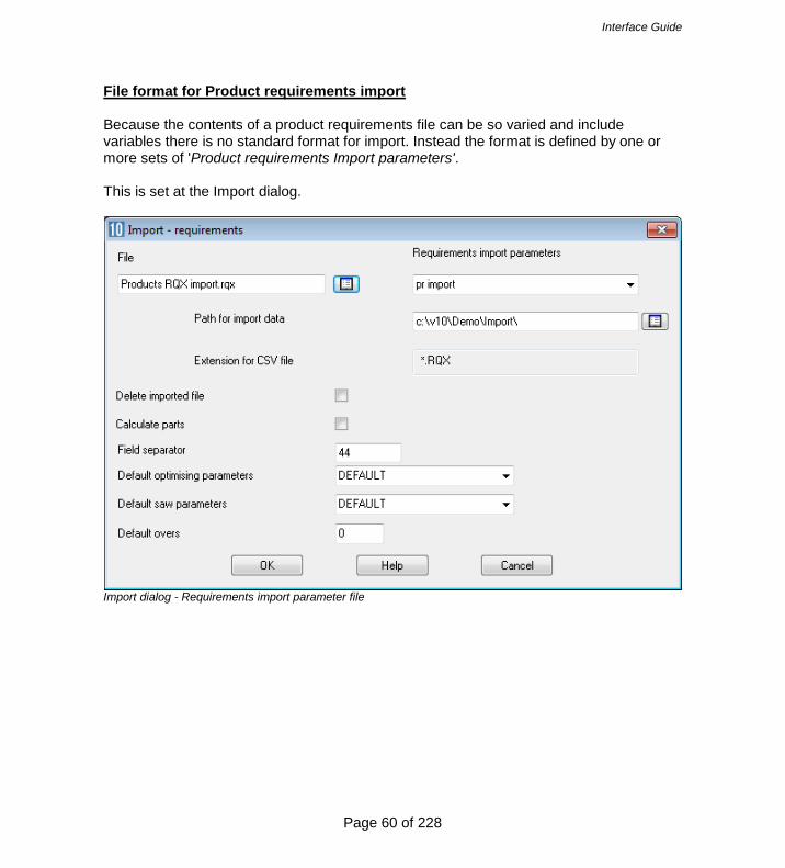
File format for Product requirements import Because the contents of a product requirements file can be so varied and include variables there is no standard format for import. Instead the format is defined by one or more sets of 'Product requirements Import parameters'. This is set at the Import dialog.
Import dialog - Requirements import parameter file

Interface Guide
Page 61 of 228
The parameter values are set via the option (Main screen - Parameters - Requirements Import parameters)
Requirement Import parameters The left hand column shows the various fields for a product and the middle column sets the position of the field in the import file. The last column is the name of the product variable (where required).

Interface Guide
Page 62 of 228
For example, the fields in the file below are: Product code, Product quantity, and Product width KTUNIT,1,1950.0 KTUNIT,3,1750.0 KYUNIT,1,1350.0 Parameter values to describe this:-
Parameter Value Product code 1 Quantity 2 Description 0 Width 3 Height 0 Depth 0
Data for variables More complex products may contain variable data. Variable data is information that changes for each item or customer e.g. the delivery date or type of door handle. If the external file already contains the answers for this variable data this can be specified in remaining variable lines. ...Variable 1 ---------------------- #6,DELIVERY ...Variable 2 ---------------------- 9,DOORMATERIAL ...Variable 3 ---------------------- 10,CARCASEMATERIAL The # symbol is used to indicate the item is in the imported header line and the number indicates the position in the header line. The other items are the fields where the variable answer for each item is located e.g, DOORMATERIAL may be TEAK for one product and OAK for another. The above values can be used to import the following file:- Import file (complex.txt) Example1,Week 32/A,standard,single,0,20/12/2015 DRESSER,2,Dressing table,Urgent,Line AS,1000.0,1100.0,600,OAK-18,OAK-15

Interface Guide
Page 63 of 228
WARDROBE,7,Wardrobe - drawer & door,Urgent, Line AP,1000.0,1800.0,600.0,OAK-18,OAK-15 BATHROOM-CABINET,4,Bathroom cabinet,Priority,Line AS,700.0,600.0,180.0,MARBLE-15,MEL-15 WARDROBE,4,Wardrobe - drawer & door,Standard,Line AP,1000.0,1800.0,600.0,TEAK-18,TEAK-15 For the import to be correct the relevant products and variables must already be set up in the product library and variables table Header lines and file Extension parameters The parameter list contains parameters to set the Header lines and the extension of the import file. Header lines - describes the number of header lines (any lines before the lines of data) in the import file. This is useful where not all the header line are related to optimising. Import - header line - specifies which (if any) of the header lines is the header line to import. Only one header line can be imported. Extension for CSV file - specifies the file extension of the import file - default: RQX. Field separator - enter an ASCII value for character defining each field e.g. '44' = comma In this example below there are four header lines and the header line to import is on line 2. 9093:/77/24-002 WK7,ORDERS FOR WEEK 7 BATCH:093221 RX RUN - TY KTUNIT,1,1950,RED < Start of product lines KTUNIT,3,1750,WHITE KYUNIT,1,1350,GREY
Interface Guide
Page 64 of 228
The values are:-
Parameter Value Header lines 4 Import - header line 2 Extension for CSV file ASC
Calculate parts On import the program can automatically create the list of parts for the product requirements. This avoids the step of moving to the Product requirements screen and optimising from that screen. This allows the parts to be optimised as part of a batch or for the part list to be optimised with a 'stand alone' process. Import from Excel files Set the parameter value for 'CSV or Excel' to '1' for Excel. If there are two files with the same name (e.g. IMPORT.XLS and IMPORT.XLSX) the XLSX file is imported. Answer table For custom products it may also be necessary to import the answers to product variables. For example, if a customer has ordered RED doors for the product that answer can be imported. It is also possible to import a set of predefined answers for a product (called an answer table), for example, a product with red doors may also include red trims, a certain type of handle ... The field for the name of the answer table is set in the 'Answer table' parameter. Product requirements data The information for requirements is outlined below. Order number or code - Each order or requirements list has a unique number or code. The order code is set to the name of the import file. Reference - The Reference is a descriptive reference for the requirements list or order which is used as a cross reference by the optimising program. This reference can be printed on product or part labels and other documents.

Interface Guide
Page 65 of 228
Optimising parameters - This is the name of the optimising parameter file for this optimisation. Optimising parameters are used to set items such as the saw kerf, type of cuts and trims. Saw parameters - This is the name of the saw parameter file for this optimisation. Saw parameters set items such as the type of saw, cutting length, stack height and so on. Overs - This is the percentage of over-production allowed for each product. If it is set it applies to each product line in the requirements list. Product code - Each product in the product library is identified by a unique code. Note that the same product code can be repeated in the requirements list for example, where the order is for a different customer, or where sizes or other features of the same basic product vary. Product information - This is extra information about the product. Sometimes this is used for the product description but can be used for other information like a product identity number or details specific to that line of the requirements. Product width, depth, height
These are the external measurements of each product. The diagram defines the width X as the leading edge of the product but this is just an example. The width can be assigned to any edge for each product - this is determined by the product formulae and the drawing in the product library. The program always uses X - for Width, Y - for Height, and Z for Depth. Quantity - quantity required

Interface Guide
Page 66 of 228
Product variables 'Product variables' are used to define the portions of a custom product that vary for each customer; items like colour, measurements, number of drawers ... For custom products the product may contain several ‘product variables’ with each standing for a variable item. The answers to these variables for each order or customer are entered as a Product requirement.
Product requirements - Product variables For example, for the Wardrobe the door material is MFC18-BEECH Where the requirements are imported the answers to the variables for each product can be included in the import file.

Interface Guide
Page 67 of 228
There are two sorts of product variables. - Global variables - apply to every item in the list - Product variables - apply to individual products In the file below the answers for global variables are included in the top line (the header line) and answer for variables for each product and included on each requirements line. WK7,ORDER FOR WEEK 7,STANDARD,SINGLE,W/E 28/07/2006,935-1072/35 UNIT/01,Kitchen cabinet,600.0,720.0,690.0,2,WHITE,GREY,BLACK UNIT/01,Kitchen cabinet,800.0,6800.0,690.0,5,RED,CREAM,WHITE There are also some fixed fields for the header line:- File name Reference Optimising parameter list name Saw parameter list name Overs percentage The following file contains a header line with fixed information and global data. WEEK7, ORDERS FOR WEEK 7,STANDARD,HOMAGHOLZMA,JONES & SON KTUNIT,1,1950,450,RED KTUNIT,3,1750,650,WHITE KYUNIT,1,1350,450,GREY The values are:-
Parameter Value Product code 1 Quantity 2 Description 0 Width 3 Height 0 Depth 4 Variable 1 #5 CUSTOMER Variable 2 5 DOORCOLOR
Variable 1 is a global variable named CUSTOMER (the # symbol indicates that it is a global variable and not a product variable) and the data is located in position 5 of the header line (the data that reads ‘Jones & Son’).

Interface Guide
Page 68 of 228
For importing answers to variables set the position in the file and give the name of the variable.
Parameter Value Product code 1 Quantity 2 Description 0 Width 3 Height 0 Depth 0 Variable 1 4 DOORCOLOR
The third column contains the variable name (e.g. DOORCOLOR) Importing variables not set in the requirements parameters To do this enter the variable name and the answer on the product line. PRODDESK,200,300,400,GREEN,OAK,@PLINTH@,500,@BACKMAT@,TEAK Items up to 'OAK' are defined by the Requirements import parameters and the remaining items are other product variables. Variables must be in the product definition e.g. of PRODDESK. The variable name must be surrounded by @ symbols and the answer must be in the next field and must not be surrounded by @ symbols. The variable/answer pairs can occur at any point, if necessary. PRODUCT1,@CARCASEMAT@,MDF-15MM,,,110,220,50,15

Interface Guide
Page 69 of 228
2.3 Import boards All the information on materials and board (or sheet) sizes is held in the Board library. Typically the Board library is maintained manually or with the Stock control module (SC) stock is updated from optimising and from orders and receipts from suppliers. With the Bargstedt SQL database and the Stock control module the board library is synchronised automatically with an external database. There are two main requirements for importing boards. - Updating the board library from an external file (for example, a list of sizes and costs provided by a supplier) - Importing boards to a board list (bypassing the Board library) Import boards to Board library The stock control module (SC) is required for this method At the main screen:- • Select: Stock • Select: Import/Adjust stock from file

Interface Guide
Page 70 of 228
The import dialog is shown.
Import/Adjust stock from file - Select the file to import The program prompts:-
Sometimes it is useful to ignore new stock as it may not be relevant to the Board library.

Interface Guide
Page 71 of 228
The program prompts:-
A file may contain both new items and updates to existing items in the library. Note - there is also an option at the Main screen: Stock - Overwrite stock which overwrites existing stock values rather than adding to them or subtracting from them. The format for the import file should be one of the following:- Board list (BRD) ASCII/Unicode CSV (BDX) User defined format – ASCII/Unicode CSV User defined format - Excel (XLS) User defined format - Excel (XLSX) Bargstedt (BESTAND.STK file) Bargstedt (SQL Server database) This is set by the System parameter: Board library import format If a ‘User defined’ format is selected also set the name of the Board import parameter file to use. This file is used to define the format of the external file and match up the fields in the external file to the Board library fields. Use the system parameter: Parameters for Import to set the file name. (See below for details of how to set up the Board library import parameters).

Interface Guide
Page 72 of 228
The result is an updated set of materials, boards and quantities in the Board library.
Board library Board library data The following sections describe the board library data. Board code - Each board has unique board code for each board size. 3/4V1S-2 1/2PB96x40 MDF18/2 Board sizes - are the length and width of the board. The length is normally the longest edge of the board but should follow the grain if the board is grained. The width is normally the shortest edge of the board but should be the edge running against the grain if the board is grained.

Interface Guide
Page 73 of 228
Board information - descriptive information about each board Board quantity - quantity of the board in stock. This is the physical quantity of stock in the board library. Quantity - allocations - shows the number of boards already allocated. Allocations act as a way of reserving boards for future use because the optimisers work on the physical quantity minus the allocation. This ensures that there are always the correct boards available for jobs that are already optimised and waiting to be cut. Only available with the Stock Control module Quantity - On order - shows the number of boards ‘On order’, that is, boards that have been recorded in the ‘Record orders’ section of the Stock control module. Only available with the Stock Control module Board cost - cost per square area of material, for example, a cost per square foot or a cost per square metre. Board limit - used to restrict the use of each board when the program produces a set of cutting patterns. 0 - do not exceed the quantity in stock 8 - assume unlimited stock (ignore the quantity in stock) 9 - exceed stock quantity if there are no other boards The limit is also used to determine the ratio in which boards are used. For example, to use two boards sizes in approximately the same proportion 1:1 or 50:50 enter a figure of ‘1’ as the limit setting against each board type. (1, ratio 1:1, 2, ratio 2;1, 3 ratio 3:1). There are also other settings for sundry or non-optimised parts. - For NO LIMIT set a value of or quantity of 99999 - Do NOT set a ratio for ONE board ONLY - Do NOT use ratios for small amounts of stock - cannot set a limit for an offcut - it is always 0 - cannot use ratios with the small quantity optimiser - With one dimensional optimisers (2,3) and strip optimiser (6) cannot use the limit values 8 or 9 if ratios set. Note - the cost is only overwritten if the cost is set to a value greater than zero and is not left blank.

Interface Guide
Page 74 of 228
Note - there are other descriptive fields for the Board library, such as 'Bin' and 'Supplier'. These are not used in the BDX format. Import boards to Board list A board list is the list of board sizes used for optimising. This is created automatically during optimisation by extracting the materials required for parts from the board library.
Board list It is sometimes useful to create the board list directly (manually or by import), for example, for 'one-off' jobs where the materials are not in the board library and are not required on a long term basis. Also it is sometimes necessary to make manual changes to the Board list to take account of shortages and bypass the values in the Board library. The import file can have the following formats:- Board list (BRD) ASCII/Unicode CSV (BDX) User defined format – ASCII/Unicode CSV
Interface Guide
Page 75 of 228
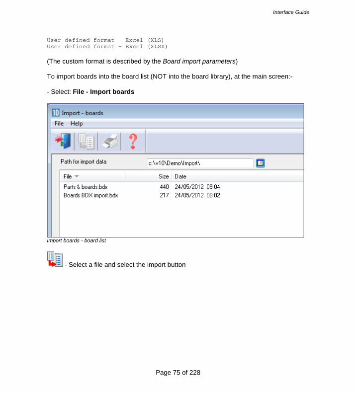
User defined format - Excel (XLS) User defined format - Excel (XLSX) (The custom format is described by the Board import parameters) To import boards into the board list (NOT into the board library), at the main screen:- - Select: File - Import boards
Import boards - board list
- Select a file and select the import button

Interface Guide
Page 76 of 228
The board list is imported
Imported board list The file can also be imported from the file tree at the main screen.
Import board list - file tree

Interface Guide
Page 77 of 228
Board import format Use the Import parameters to set up the format for the board import file. The Board options are towards the foot of the dialog.

Interface Guide
Page 78 of 228
Import board list - dialog The formats are:-
Board list order – ASCII/Unicode CSV (BDX) User defined order – ASCII/Unicode CSV User defined order - Excel (XLS) User defined order - Excel (XLSX)
For the user defined formats the format is set via the Board import parameters (Main screen - Parameters - Board import parameters) Board import parameters These files define how the fields in the external file to import map on to the board library or board list fields.

Interface Guide
Page 79 of 228
It is possible to create as many parameters files as required; for example, separate files for different external file formats. If importing to the Board library and to Board lists different files may be required for each type of import as the external files are likely to be different.
Board import parameters Use the parameters to describe the format of the external (file to import). A simple ASCII external file is, for example:- BRD1,MFC15,2440.0,1220.0,25,18 BRD2,MDF18,2440.0.0,1220.0,30,15 BRD3,MDF18,1830.0,1230.0,10,18 In this example there is one line for each board and the information shown on each line is:- - board code - material code - length (millimetres) - width (millimetres)

Interface Guide
Page 80 of 228
- quantity - thickness This format is described, by the parameters, as follows:- ...Code -------------------- 1 ...Material -------------------- 2 ...Length ---------------------- 3 ...Width ----------------------- 4 ...Thickness ------------------- 6 ...Information ----------------- 0 ...Quantity -------------------- 5 Each parameter is a field in the part list and the parameter value is the position of that field in the external ASCII file. Here is the same data in another format: 25,BRD1,MFC15,2440.0,1220.0,18 30,BRD2,MDF18,2440.0.0,1220.0,15 10,BRD3,MDF18,1830.0,1230.0,18 This is the same data as the first example but the items are now in a different order:- - quantity - board code - material - width - length - thickness ...Code ------------------------ 2 ...Material -------------------- 3 ...Length ---------------------- 4 ...Width ----------------------- 5 ...Thickness ------------------- 6 ...Information ----------------- 0 ...Quantity -------------------- 1 Here is a similar example for importing boards measured in inches. 25,BRD1,MFC15,96-1/2,48 30,BRD2,MDF18,96-1/2,48 10,BRD3,MDF18,72,48-3/4 ...Extension for CSV file -- BDX

Interface Guide
Page 81 of 228
Note - at the foot of the list that there is a parameter to specify the extension for the import file; the default is BDX. The path for the file is specified in the program as the Path for Import Number of header lines - Enter the number of header lines. Default value is 0 and the range is 0-99. Only applies when the Import parameter: Board import format is set for user defined formats. - The value column specifies a field position in the import file. This can be in the range 0 to 200. There are less fields to import than this but in some import files there will be fields that have to be ignored. - The 'Extension for CSV file' parameter is used to specify the file extension of the files to be imported. e.g. CSV, BDX, XLS, XLSX Field separator - enter an ASCII value for character defining each field e.g. '44' = comma Notes - When importing to a board list the following fields are not used. Material description Maximum book height Board import file format (BDX) Board code (50) Quantity (5) Material (50) Length (9) Width (9) Thickness (7) Cost (5) Limit (1) Board information (50) Material description (50) Grain (1) Yes=1, No=0, 2=X Maximum book height (4)

Interface Guide
Page 82 of 228
Board parameter name (50) Material density (6) Board type (1) Stock board=0, Offcut in manual storage area=1, Offcut in automatic storage area=2 Bin (25) Supplier (50) Material parameter name (50) Material picture/colour (50) file name or RGB(###:###:###) The number in brackets shows the maximum length of each field but each field must also be comma separated and can be shorter than the maximum. Only the first two items (board code and quantity) are essential the other items are optional. Material parameter name - stored in the Board library on import. Not used when importing boards to a board list. B27/1,250 B28/1,3000 B35/021/009-ASH,-150 B36,0,MFC15,2440.0,1220.0,15.0,42.25,0 SP8,345 Note - not all the fields specified in the BDX format are used when importing into a Board list (as these fields are not used in the Board list). The fields NOT imported are:- Material description (extra description field in Board library) Max book height Material density These fields must be present where there are following fields. Import parameter to include the list of boards on import For the import of external part lists it is sometimes convenient to also import the board list at the same time, Quite often the two lists are created together in the external system. At the Import parameters screen:- - Check the box to also import the board list The program automatically works out the correct board list name and extension from the settings for the import type for parts and boards and the extension used (this is either implied by the import type or taken from the Board import parameters).

Interface Guide
Page 83 of 228
Import part format: Part list order – ASCII/Unicode CSV (PNX) Import board format: Board list order – ASCII/Unicode CSV (BDX) Part list name: MyBoards.pnx Board list name: MyBoards.bdx 2.4 Import Parts / Boards / Patterns - Pattern Exchange Format (PTX) The Pattern Exchange format is a standard format for describing parts, boards, patterns and cutting information and can be used for both Import and Export. The file can be either an ASCII file or an Access MDB database file (the full details for the format are in Section 3). Import Parts and Boards (PTX) Several manufacturers use the PTX format for exchanging data. The import format is set at the Import dialog (Main screen - File - Import parts (boards) - File Parameters)
Import PTX - set format

Interface Guide
Page 84 of 228
The format for PTX is: Parts & Boards ASCII/Unicode CSV (PTX). The PTX file can contain both parts and boards. To import (once the format is set):- - Select: File - Import parts
Import parts and boards - PTX

Interface Guide
Page 85 of 228
The part list and board list are imported.
Import parts - PTX The PTX format can also be imported from an MDB file:Parts & Boards - Access (MDB).
Interface Guide
Page 86 of 228
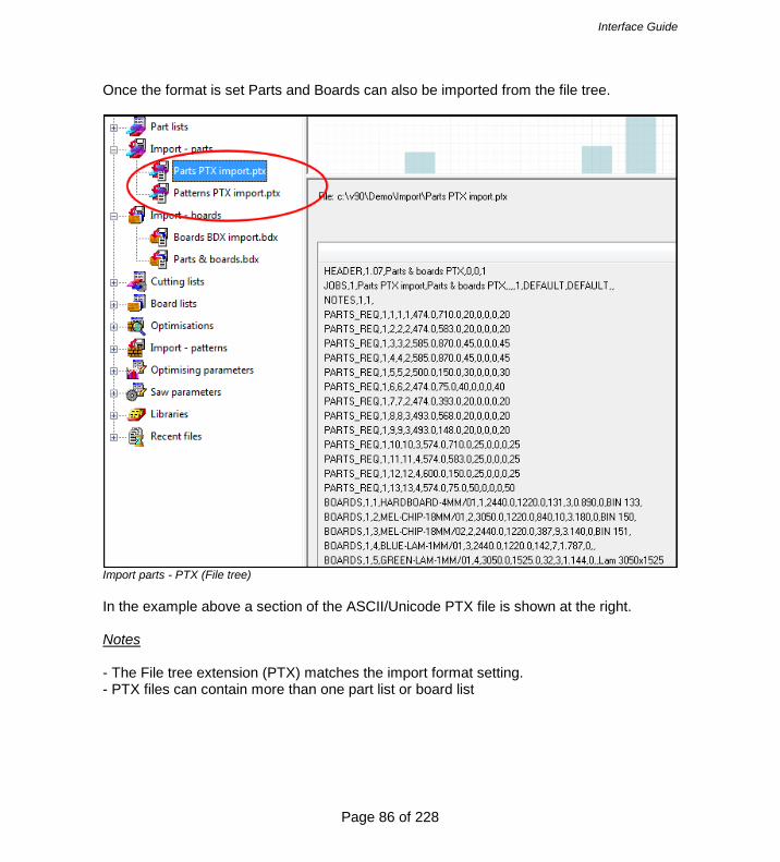
Once the format is set Parts and Boards can also be imported from the file tree.
Import parts - PTX (File tree) In the example above a section of the ASCII/Unicode PTX file is shown at the right. Notes - The File tree extension (PTX) matches the import format setting. - PTX files can contain more than one part list or board list

Interface Guide
Page 87 of 228
Import patterns - Pattern Exchange Format The optimising program usually produces patterns so it is rare to need to import patterns to the program. (The main use for the Pattern Exchange format is to export data for patterns to other systems and machines, or, for manufacturers to use sections of the PTX data for controlling other production processes). However, in some cases it is useful to import patterns to the Optimising software, for example, where special patterns have been created manually and do not need to be optimised.

Interface Guide
Page 88 of 228
Use the Pattern Exchange format for this import (Main screen - Import patterns - File - Parameters)
Import parameters - Patterns The pattern import parameters are towards the foot of the dialog. Select the one of the pattern exchange formats, for example: Pattern Exchange – ASCII/Unicode CSV (PTX) (The other options are for special situations where patterns are imported from other systems for further processing). To import patterns (once the format is set), at the main menu:-

Interface Guide
Page 89 of 228
• Select: File - Import patterns The screen displays an Import dialog select the pattern exchange file (PTX) to import.
Import patterns - PTX
- Select a file and select the import button

Interface Guide
Page 90 of 228
The result is an imported run (set of patterns).
Pattern preview - imported patterns
Interface Guide
Page 91 of 228
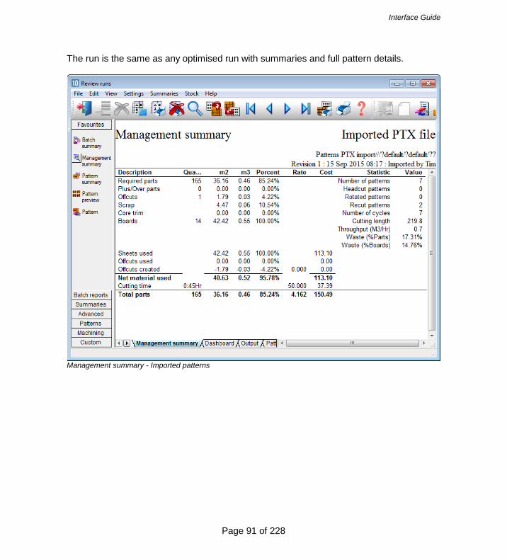
The run is the same as any optimised run with summaries and full pattern details.
Management summary - Imported patterns

Interface Guide
Page 92 of 228
The patterns operate in the normal way.
Pattern details - Imported pattern Note - import patterns also imports the parts and boards as these are needed for the patterns. File tree - also import patterns by selecting the file at the file tree on the main screen under the branch 'Import patterns'.
Interface Guide
Page 93 of 228
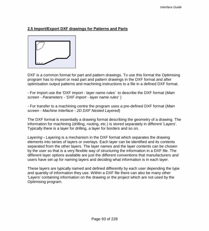
2.5 Import/Export DXF drawings for Patterns and Parts
DXF is a common format for part and pattern drawings. To use this format the Optimising program has to import or read part and pattern drawings in the DXF format and after optimisation output patterns and machining instructions to a file in a defined DXF format. - For import use the 'DXF import - layer name rules' to describe the DXF format (Main screen - Parameters - 'DXF import - layer name rules' ) - For transfer to a machining centre the program uses a pre-defined DXF format (Main screen - Machine Interface - 2D DXF Nested Layered) The DXF format is essentially a drawing format describing the geometry of a drawing. The information for machining (drilling, routing, etc.) is stored separately in different 'Layers'. Typically there is a layer for drilling, a layer for borders and so on. Layering - Layering is a mechanism in the DXF format which separates the drawing elements into series of layers or overlays. Each layer can be identified and its contents separated from the other layers. The layer names and the layer contents can be chosen by the user so that is a very flexible way of structuring the information in a DXF file. The different layer options available are just the different conventions that manufacturers and users have set up for naming layers and deciding what information is in each layer. These layers are typically named and defined differently by each user depending the type and quantity of information they use. Within a DXF file there can also be many other 'Layers' containing information on the drawing or the project which are not used by the Optimising program.

Interface Guide
Page 94 of 228
Working with DXF based parts Where parts are based on DXF files there are a number of ways of working. - Use DXF parts directly in part lists - Import DXF parts into the Part library - Import DXF parts into the Machining library Once the parts are in a part list they can be optimised and transferred to a machining centre in the usual way. Use DXF parts directly in part lists - Copy the DXF files to the directory set by the system parameter: Path for Import data - Move to a part list - Select: File - Properties - Set the drawing source for the part list as: DXF files (this can be different for each part list)

Interface Guide
Page 95 of 228
At the part list the DXF parts are now available from the selection dialog.
Part list - DXF parts When using the DXF drawing source (Part list parameters) the setting for 'DXF import - layer name rules' must also be set to describe the DXF format. Import DXF parts to the Part library - Copy the DXF files to the directory set by the system parameter: Path for Import data - Move to the Part library - Select: Edit - Import DXF drawings - Select the required DXF drawing The item is now stored in the Part library and there is a drawing in the Machining library.
Interface Guide
Page 96 of 228
- Move to a part list - Select: File - Properties - Set the drawing source for the part list as: Part library (this can be different for each part list) At the part list the DXF parts in the Part library are now available from the selection dialog. Import DXF parts to the Machining library - Copy the DXF files to the directory set by the system parameter: Path for Import data - Move to the Machining library - Select: File - Merge DXF - Choose the directory with the DXF files - Select the required DXF drawing The item is now stored in the Machining library. - Move to a part list - Select: File - Properties - Set the drawing source for the part list as: Machining library (this can be different for each part list) At the part list the DXF parts in the Machining library are now available from the selection dialog. Machining instructions For parts processed at a Machining centre the DXF file also contains machining instructions. This format can be different for each user. Use the 'DXF import - layer name rules' to describe this format. DXF import - layer name rules Use these parameters to describe the layer structure of a DXF file for machining information. This information is required if DXF files are used as a source for parts, in the part list, part library or machining library. At the main menu:- • Select: Parameters - DXF import - layer name rules

Interface Guide
Page 97 of 228
The program displays a dialog.
DXF layer names - Enter a layer name or - Select a layer name via the list box (Click on the Layer column to pop up the select button) Initially the program prompts to select the folder containing the DXF files. Select the required folder. This selection is retained for future sessions. If no names are available or more layer names are required a list of layer names can be prepared by scanning existing DXF files - for details see: Scan - DXF. Instruction Enter the type of instruction stored in the layer name. Some examples of available types are:- Vertical drill Horizontal drill Saw groove Circle router Groove router

Interface Guide
Page 98 of 228
Arc router End groove Contour Text Border Safety Border Free form pocket In the next columns enter the information for Depth, Width, Zstart and Tool where it applies for each instruction type. This is information that is NOT in the DXF layer but needs to be set for Machining. The information required for each machining type is. Vertical drill: Depth, Tool Horizontal drill: ZStart, Tool Saw groove: Width, Depth, Tool Circle router: Depth, Width, Tool Groove router: Width, Depth, Tool Arc router: Width, Depth, Tool End groove; Width, Tool Contour: Depth Text: Border: - At the Tool column click on the button to pop up the tool dialog to enter the Tool information. Direction of imported contours / free form pockets The column 'Direction' is for specifying the direction of contours and free form pockets. This is available where the instruction is a contour or a free form pocket. Enter one of the following values:- Blank - contour/pocket direction depends on the way it was drawn in the original DXF drawing) CW - contour/pocket is drawn in the machining library in a clockwise direction CCW - contour/pocket is drawn in the machining library in a counter clockwise direction
Interface Guide
Page 99 of 228
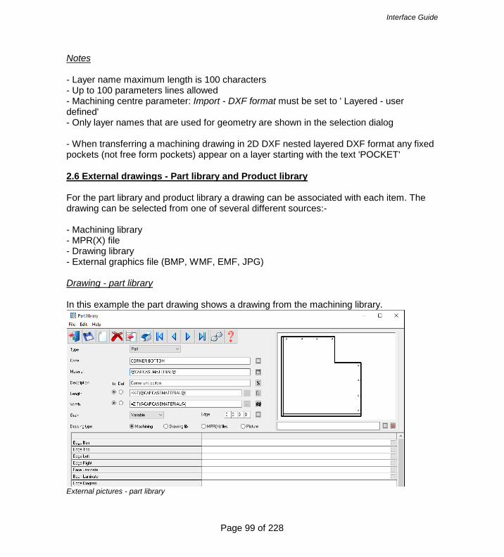
Notes - Layer name maximum length is 100 characters - Up to 100 parameters lines allowed - Machining centre parameter: Import - DXF format must be set to ' Layered - user defined' - Only layer names that are used for geometry are shown in the selection dialog - When transferring a machining drawing in 2D DXF nested layered DXF format any fixed pockets (not free form pockets) appear on a layer starting with the text 'POCKET' 2.6 External drawings - Part library and Product library For the part library and product library a drawing can be associated with each item. The drawing can be selected from one of several different sources:- - Machining library - MPR(X) file - Drawing library - External graphics file (BMP, WMF, EMF, JPG) Drawing - part library In this example the part drawing shows a drawing from the machining library.
External pictures - part library

Interface Guide
Page 100 of 228
In this example the product drawing is from an external picture (jpg) file.
External picture - product library - External graphics files are placed in directory set by the system parameter: Path for pictures. If this path is not set the files are in the directory set by the system parameter: Path for data - MPR(X) files are located in the directory set by the system parameter: Path for MPR(X) files - Different parts can be linked to the same drawing or there can be a one to one link between parts and drawings.

Interface Guide
Page 101 of 228
2.7 Import from file - part library
The import options are on the Edit menu, for example:- - Select: Edit - Import from file The program displays a list of files (from path set by the System Parameter: Path for data' - Select a part list to import

Interface Guide
Page 102 of 228
If a part code already exists in the part library the program prompts to overwrite the code or stop the import. Setup of External files - The file type can be CSV (ASCII/Unicode text file) or the Excel formats XLS, XLSX; this is set via (Part library screen - File - Parameters). To import an external file directly to the part library the format of the external file must follow a fixed layout. part code material description default length length default width width grain quick edge codes cost drawing type drawing code information boxes Default length?; default width? - used to set the default check box beside the length and width fields at the part library 0 = default box is not set 1 = default box is set Material code starts with + record is a fitting Material code starts with - record is an operation Grain 0=No, 1=Yes, 2=X, 3=Variable Cost - only applies to fittings and operations Drawing type - 0=file name, 1=machining library, 2=drawing library Drawing code - where the drawing type is 0 the drawing code is a file name and extension, otherwise it is a drawing code Part library - Import part lists

Interface Guide
Page 103 of 228
Part lists can also be imported to the part library via the option: Edit - Import from Part list 2.8 Import product data At the product library screen there are several options to export data. - Import product - Import library Import product The program has an option to export data for a single product to a PLE file. This file can be imported to any product library using this import option. If the product is BASE-OVEN-HSE the file is typically: BASE-OVEN-HSE.PLE The PLE format is an internal format. Import library This option imports an MDB file and creates the following libraries/tables: Product library Part library Variable table Lookup table Formula table The structure of the MDB file must match the specification for the librar. For details of the format see the section on 'Export product data'. 2.9 Import Quote and Orders When working with Quotes it can be the case that the data is generated elsewhere, for example in a Sales system.

Interface Guide
Page 104 of 228
Quotes and orders
The import process is as follows At the main screen:-
- Select: File – Import - Quote
Interface Guide
Page 105 of 228
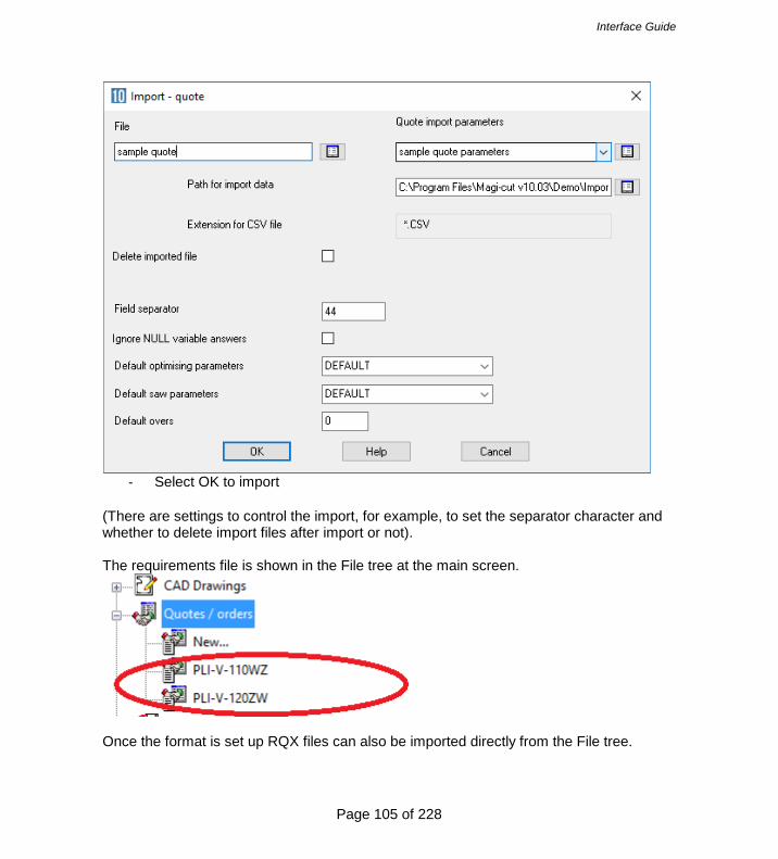
- Select OK to import
(There are settings to control the import, for example, to set the separator character and whether to delete import files after import or not). The requirements file is shown in the File tree at the main screen.
Once the format is set up RQX files can also be imported directly from the File tree.

Interface Guide
Page 106 of 228
If importing products, the product code must represent products already set up in the product library. File format for Quote/Orders import Because the contents of a quote / orders file can be so varied and include variables, information boxes and variable header data, there is no standard format for import. Instead the format is defined by one or more sets of 'Quote requirements Import parameters'. This is set at the Quote Import dialog.
Interface Guide
Page 107 of 228
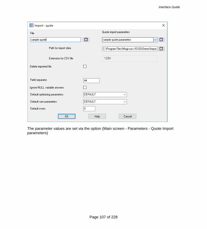
The parameter values are set via the option (Main screen - Parameters - Quote Import parameters)

Interface Guide
Page 108 of 228
There are two main sections to this page. A header section and Item section. The header section specifies the position in the import files header line, one position for each header item. The item section specifies the position in the field in the main body of the file. For example, the following sample has one header line and three items lines. The header line fields are ORDER DATE, CUSTOMER CODE, CUSTOMER NAME, DELIVERY DATE. The item data is CODE,ENTRY TYPE, INFORMATION, WIDTH,HEIGHT,DEPTH<QUANTITY 28/05/2012,CUS123,test customer 1,28/05/2012 BASE-SINGLE,0,Single base unit,550.0,900,0,600.0,1, F-UNIT-DOOR,1,Fixed size unit door,500,0,600.0,,4 Z-SINGLE,3,Single Knob,,,,4

Interface Guide
Page 109 of 228
They type of item loaded depends on the entry type setting. The following values determine the item type Product = 0 Part = 1 Free_form/phrases = 2 Fitting = 3 Operation =4

Interface Guide
Page 110 of 228
3. Pattern Exchange File - Specification - V1.14 1. INTRODUCTION This section describes a data structure for the exchange of cutting lists and patterns for sheet material between various design programs, optimising packages, and panel saw controllers. This data structure contains the information that is required for transferring cutting lists to an optimising package and for transferring optimised cutting patterns with label information to a panel saw. The data structure can be created in two formats as follows.
• ASCII/Unicode comma-separated file • Access database The data structure consists of 12 record types each with a number of fields. In the ASCII/Unicode file each record type is represented by a token which begins each line and in the database each record type is a separate table. Each record type and each field name are in uppercase and use underscores between separate words. No table name or field name is more than 10 characters. 2. RECORD TYPES & TABLE NAMES The ‘cutting list’ record types are as follows. HEADER - general information describing the complete data structure (or file) JOBS - header data for each job (cutting list or optimised run) PARTS_REQ - basic requirement details for each item in the cutting list PARTS_INF - standard information about each part PARTS_UDI - user-defined information about each part PARTS_DST - destacking information about each part BOARDS - information about each item in the board (stock) list MATERIALS – information about each material type NOTES - other information for a job The ‘post-optimisation’ records are: OFFCUTS - record describing each off-cut produced PATTERNS - pattern header records - one for each cutting pattern PTN_UDI - information used to match parts in a strip - one for each strip in the pattern CUTS - cutting instructions – occur many times per pattern – once for each cut required VECTORS – vector graphics describing the pattern 3. FORMAT The ASCII/Unicode version of the file uses standard comma-separated format, and has the suffix .PTX (PaTtern eXchange). The main part of the filename could be the job/order number or batch name if the file contains multiple jobs. Examples:-

Interface Guide
Page 111 of 228
01234.PTX ABC123-1.PTX Note that the structure allows for the ASCII file to contain more than 1 cutting list or run if necessary, for example it could contain a batch of runs. Note that there may be restrictions on the file name because some controllers will, for example, only accept 5 digits for the job number. All normal CSV format conventions apply, including optional use of quotation marks around text data. Leading spaces are ignored. Trailing commas (separators) are not necessary. Text fields containing commas must be enclosed in quotes. The format and size restrictions for each field are tabulated in section 18. Note, that the limitations (eg. max length of material code) will vary according to the implementation and specification of the saw. All ‘index numbers’ must be integer values, starting at 1 for the first record, and incrementing consecutively up to the maximum specified. Note, in particular that all part, board, pattern and cutting records must contain the appropriate job index number showing which job they relate to. The Access database version stores each record type in a separate table. The file has the standard extension of MDB. Examples: 01234.MDB BATCH32.MDB

Interface Guide
Page 112 of 228
4. HEADER - GENERAL INFORMATION
HEADER – VERSION, TITLE, UNITS, ORIGIN, TRIM_TYPE The header record contains descriptive and global information for the job. This record appears as a line in the ASCII/Unicode file. In the Access database this information will be stored in the database properties.
VERSION - File version (1.08) TITLE - File title UNITS - Measurement mode = 0 (metric), 1(decimal inches). ORIGIN - This field indicates the origin for the VECTOR drawing records. The origin for the CUT records is assumed to be 0 (top left). 0 = top to bottom - left to right 1 = top to bottom – right to left 2 = bottom to top – left to right 3 = bottom to top – right to left TRIM_TYPE - Indicates whether the waste strip/piece is cut first or last. That is, is the fixed trim done on the leading edge or as a final trim? 0 = trim waste piece first 1 = trim fixed trim first ASCII/Unicode & Database examples HEADER,1,“This is an example”,0,0,1 HEADER TABLE
VERSION TITLE UNITS ORIGIN TRIM_TYPE
1 This is an example
0 0 1

Interface Guide
Page 113 of 228
5. JOBS – JOB RECORD JOBS, - JOB_INDEX, NAME, DESC, ORD_DATE, CUT_DATE, CUSTOMER, STATUS, OPT_PARAM, SAW_PARAM, CUT_TIME, WASTE_PCNT This record contains data about each job contained in the file. These records are optional and in the absence of job records all parts and patterns are assumed to belong to the same job. JOB_INDEX - Unique index number used to link other records to an appropriate job NAME - Job number/name – reference for job DESC - Job description/title - title of job ORD_DATE – Date of order (DD/MM/YYYY) CUT_DATE – Date for cutting/delivery (DD/MM/YYYY) CUSTOMER - Customer code or name STATUS - Status of the job. 0 - not optimised 1 - optimised 2 - optimise failed Note: there may be a range of other error codes OPT_PARAM - Optimising parameter file name SAW_PARAM - Saw parameter file name CUT_TIME - Total cutting time for the job in seconds WASTE_PCNT - Overall percentage waste as a percentage of board area ASCII/Unicode & Database examples JOBS,1,ORD1234,SAMPLE JOB – CUSTOMER WOODCO,17/01/1999, 22/01/1999,WOODCO,1,STANDARD,ANGLE,821,12.36 JOBS TABLE JOB_INDE
X NAME DESC ORD_DATE .....
1 ORD1234 SAMPLE JOB - CUSTOMER WOODCO 17/01/1999 .....

Interface Guide
Page 114 of 228
6. PARTS_REQ – PART REQUIREMENT RECORD PARTS_REQ - JOB_INDEX, PART_ INDEX, CODE, MAT_INDEX, LENGTH, WIDTH, QTY_REQ, QTY_OVER, QTY_UNDER, GRAIN, QTY_PROD, UNDER_PROD_ERROR, UNDER_PROD_ALLOWED, UNDER_PROD_PLUSPART This record contains data about each different size (or line item) in the cutting list. This record is used to provide details about each part (over and above cut sizes). JOB_INDEX - Index number used to link this record to other records for this job. PART_INDEX - Index number to link this record with other associated part records CODE - Part code or description. MAT_INDEX - Index of material used for this part. LENGTH - Cut length of part shown in appropriate measurement unit WIDTH - Cut length of part shown in appropriate measurement unit QTY_REQ - number of pieces this size QTY_OVER - allowed over production QTY_UNDER - allowed under production. GRAIN – 0 = No grain/part can be rotated, 1 = grain along the length of the board/part cannot be rotated 2 = grain along the width of the board/part must be rotated QTY_PROD - quantity of parts produced by patterns UNDER_PROD_ERROR - quantity of parts not produced because of an error UNDER_PROD_ALLOWED - quantity of parts not produced because of allowed under production UNDER_PROD_PLUSPART - quantity of plus parts not produced ASCII/Unicode & Database examples PARTS_REQ,1,1,SD900X,1,890.0,645.5,50,0,2,0,50,0,0,0 PARTS_REQ TABLE JOB_INDEX PART_INDEX CODE MAT_INDEX LENGTH WIDTH .....
1 1 SD900X 1 890.0 645.5 .....
Interface Guide
Page 115 of 228
7. PARTS_INF – STANDARD PART INFO RECORD PARTS_INF - JOB_INDEX, PART_INDEX, DESC, LABEL_QTY, FIN_LENGTH, FIN_WIDTH, ORDER, EDGE1, EDGE2, EDGE3, EDGE4, EDG_PG1, EDG_PG2, EDG_PG3, EDG_PG4, FACE_LAM, BACK_LAM, CORE, DRAWING, PRODUCT, PROD_INFO, PROD_WIDTH, PROD_HGT, PROD_DEPTH, PROD_NUM, ROOM, BARCODE1, BARCODE2, COLOUR, SECOND_CUT_LENGTH, SECOND_CUT_WIDTH This optional record contains standard information about each different size (or line item) in the cutting list. One use of this record is to hold data for label printing. JOB_INDEX - Index number used to link this record to other records for this job. PART_INDEX - Index number linking this record with other part records. DESC - A second part description LABEL_QTY - Number of copies of the label for this part. 0 = no labels for this part default if not specified =1 FIN_LENGTH - Length of part after edging and trimming FIN_WIDTH - Width of part after edging and trimming ORDER - Original order/job/work number which part relates to EDGE1 - Code or description of edging for bottom (length) edge EDGE2 - Code or description of edging for top (length) edge EDGE3 - Code or description of edging for left (width) edge EDGE4 - Code or description of edging for right (width) edge EDG_PG1 – Program or operation code for bottom (length) edge EDG_PG2 - Program or operation code for top (length) edge EDG_PG3 - Program or operation code left (width) edge EDG_PG4 - Program or operation code for right (width) edge FACE_LAM - Code/description of laminate material for face (topside) of part BACK_LAM - Code /description of laminate material for back (underside) of part CORE_MAT - Code or description of core material PALLET – Pallet layout (stacks in length and width) DRAWING - Name of drawing file, drill program or CNC program for machine centre PRODUCT - Product or cabinet code or template name to which part belongs PROD_INFO - Description of product or cabinet PROD_WIDTH - External dimension of product or cabinet PROD_HGT - External dimension of product or cabinet PROD_DEPTH - External dimension of product or cabinet PROD_NUM - Item number of cabinet in room ROOM - Room or floor or group item number for cabinet BARCODE1 - data for 1st barcode – as text string BARCODE2 - data for second bar code – as text string COLOUR - The extended colour name. SECOND_CUT_LENGTH - Length of part prior to second cut SECOND_CUT_WIDTH - Width of part prior to second cut

Interface Guide
Page 116 of 228
ASCII/Unicode & Database examples PARTS_INF,1,2,BOTTOM,1,690.0,475.0,ORD1234,GREY-1MMPVC,, GREY-1MMPVC,,Edge PG1,Edge PG2,Edge PG3,Edge PG4,GREYLAM,GREYLAM, MDF18,2X1,BU-SIDE-CNC,BU4DW,4 Dwr Base Unit,600.0,890.0,570.0,1,1, 0690004750,0012301,WHITE-ASH-325,700.0,485.0 PARTS_INF TABLE
JOB_INDEX PART_INDEX DESC LABEL_QTY FIN_LENGTH FIN_WIDTH .....
1 2 BOTTOM 1 690.0 475.0 .....
8. PARTS_UDI - USER DEFINED PART INFO RECORD PARTS_UDI - JOB_INDEX, PART_INDEX, INFO1, INFO2, …. INFO60 This optional record contains user-defined information about each different size (or line item) in the cutting list. One use of this data is for label printing. JOB_INDEX - Index number used to link this record to other records for this job. PART_INDEX - Index number linking this record with other part records INFOn There are up to 60 information fields. The name of each field is INFO followed by the field number. The fields may be used for any purpose such as customer details, dates, CNC operations, and other items not included in the other part records. ASCII/Unicode & Database examples PARTS_UDI,1,3,CNC84,Smith & Co,20-APR-1999 PARTS_UDI TABLE
JOB_INDEX PART_INDEX INFO1 INFO2 INFO3 .....
1 3 CNC84 Smith & Co 20-APR-1999 .....
Interface Guide
Page 117 of 228
9. PARTS_DST - DESTACKING PART INFO RECORD PARTS_DST - JOB_INDEX, PART_INDEX, PART_LAY_L,PART_LAY_W, PART_LAY_O,STK_HGHT_Q, STK_HGHT_D, STATION, QTY_STACKS, BTM_TYPE, BTM_DESC, BTM_MATL, BTM_LENGTH, BTM_WIDTH, BTM_THICK, OVER_LEN, OVER_WID, BTM_LAY_L, BTM_LAY_W, TOP_TYPE, TOP_DESC, TOP_MATL, TOP_LENGTH, TOP_WIDTH, TOP_THICK, TOP_LAY_L, TOP_LAY_W, SUP_TYPE, SUP_DESC, SUP_MATL, SUP_LENGTH, SUP_WIDTH, SUP_THICK, SUP_LAY_L, SUP_LAY_W,STATION2 This optional record contains destacking information about each different size (or line item) in the cutting list. JOB_INDEX - Index number used to link this record to other records for this job. PART_INDEX - Index number linking this record with other part records PART_LAY_L - Part layout - number of parts per stack in length PART_LAY_W - Part layout - number of parts per stack in width PART_LAY_O - Part layout – orientation STK_HGHT_Q – Stack height – quantity of pieces STK_HGHT_D - Stack height – dimension STATION - Station number QTY_STACKS – Total number of stacks (pallets) for this part BTM_TYPE – Bottom destacking type BTM_DESC - Bottom description BTM_MATL – Bottom baseboard material BTM_LENGTH - Length of bottom baseboard/pallet BTM_WIDTH - Width of bottom baseboard/pallet BTM_THICK -Thickness of bottom baseboard/pallet OVER_LEN – Overhang/oversize per side in length OVER_WID - Overhang/oversize per side in width BTM_LAY_L - Layout of bottom baseboards/pallets in station in length BTM_LAY_W - Layout of bottom baseboards/pallets in station in width TOP_TYPE – Top cover type OP_DESC - Top baseboard/cover description OP_MATL – Top baseboard material TOP_LENGTH - Length of top baseboard/cover TOP_WIDTH - Width of top baseboard/cover TOP_THICK -Thickness of top baseboard/cover TOP_LAY_L - Layout of top baseboards in length TOP_LAY_W - Layout of top baseboards in width SUP_TYPE – Support type SUP_DESC – Support description SUP_MATL – Support material SUP_LENGTH – Length of support SUP_WIDTH - Width of support SUP_THICK – Thickness of support SUP_LAY_L – Support layout in length SUP_LAY_W – Support layout in width STATION2 - Alternative station number
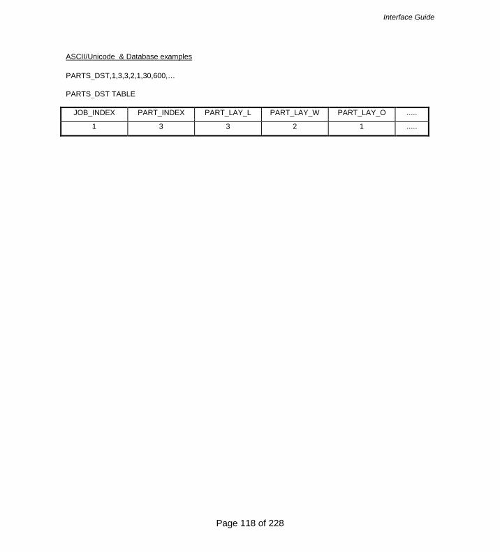
Interface Guide
Page 118 of 228
ASCII/Unicode & Database examples PARTS_DST,1,3,3,2,1,30,600,… PARTS_DST TABLE
JOB_INDEX PART_INDEX PART_LAY_L PART_LAY_W PART_LAY_O .....
1 3 3 2 1 .....

Interface Guide
Page 119 of 228
10. BOARDS – BOARD RECORD BOARDS - JOB_INDEX, BRD_INDEX, CODE, MAT_INDEX, LENGTH, WIDTH, QTY_STOCK, QTY_USED, COST, STK_FLAG, INFORMATION, MAT_PARAM, GRAIN, TYPE, BIN, SUPPLIER These records contain details of the board/sheet sizes to be used; one record for each different size/material. JOB_INDEX - Index number used to link this record to other records for this job. BRD_INDEX - index number linking this record with the PATTERNS records for this job. CODE – Board code - usually the stock code for the sheet size. MAT_INDEX - Index of material used for this part. LENGTH - Size of sheet in appropriate measurement unit. WIDTH - Size of sheet in appropriate measurement unit. QTY_STOCK - Total number of sheets available – default 99999 (0=none) QTY_USED - Total number of sheets this size used in patterns COST - Cost per sq. metre or sq. foot according to measurement unit STK_FLAG – Flag to indicate action if insufficient stock INFORMATION - Extra descriptive details about the sheet MAT_PARAM - Material parameters file name GRAIN – 0 = No grain, 1 = grain along the length of the board 2 = grain along the width of the board TYPE – 0 = Stock board 1 = Offcut 2 = Automatic offcut BIN - Board location SUPPLIER - Board supplier ASCII/Unicode & Database examples BOARDS,1,1,WLAM15MM-1,1,2550.0,1525.0,100, 7, 8.50,0 BOARDS TABLE JOB_INDE
X BRD_INDEX CODE MAT_INDEX LENGTH WIDTH .....
1 1 WLAM15MM-1 1 2550.0 1525.0 .....

Interface Guide
Page 120 of 228
11. MATERIALS – MATERIAL RECORDS MATERIALS - JOB_INDEX, MAT_INDEX, CODE, DESC, THICK, BOOK, KERF_RIP, KERF_XCT, TRIM_FRIP, TRIM_VRIP, TRIM_FXCT, TRIM_VXCT, TRIM_HEAD, TRIM_FRCT, TRIM_VRCT, RULE1, RULE2, RULE3, RULE4, MAT_PARAM, GRAIN, PICTURE, DENSITY These records define the different material types. There should be a least one of these records in data structure. This record is used to pass a detailed material description, the thickness and other parameters which may vary according to material type. JOB_INDEX - Index number used to link this record to other records for this job. MAT_INDEX - Unique index of material used to link this record to other records CODE – Material code DESC - Material description THICK - Material thickness in appropriate measurement mode BOOK - Max sheets per book, reflects cutting height of saw KERF_RIP - Rip saw kerf – in unit of measurement KERF_XCT - Crosscut saw kerf – in unit of measurement TRIM_FRIP - Fixed rip trim – includes saw kerf – amount sheet size is reduced by TRIM_VRIP - Minimum waste rip trim - minimum size of falling waste including saw kerf TRIM_FXCT - Fixed crosscut trim – includes saw kerf TRIM_VXCT - Minimum waste crosscut trim - minimum size of falling waste including saw kerf TRIM_HEAD - Internal head cut trim – includes saw kerf TRIM_FRCT - Fixed recut trim – includes saw kerf TRIM_VRCT - Minimum waste recut trim - minimum size of falling waste including saw kerf RULE1 - Optimisation rule 1 – cut nesting limit – 1 to 9 (e.g. 3 = allow third phase recuts) RULE2 - Optimisation rule 2 – head cuts allowed (0=No, 1 =Yes) RULE3 - Optimisation rule 3 – board rotation allowed (short rip) (0=No, 1=Yes) RULE4 - Optimisation rule 4 – show separate patterns for duplicate parts (0=No 1=Yes) MAT_PARAM - Material parameters file name GRAIN – 0 = No grain, 1 = grain along the length of the board 2 = grain along the width of the board PICTURE - Solid colour (e.g. "RGB(255:0:0)") or image file (e.g. "Teak.bmp") DENSITY - Material density in metric tons per m3 or pounds per ft3 depending on the current measurement mode. The saw kerf and trims are optional. Note that it is assumed that one of the two rip trims will be constant and the other rip trim includes the waste strip. Either (a) the leading edge is trimmed and the waste strip comes out last, or (b) the waste strip is removed by the first rip and the last rip is a constant trim. This assumption also applies to cross cut trims and recut trims.

Interface Guide
Page 121 of 228
ASCII/Unicode & Database examples MATERIAL,1,1,WHITE18,"White laminate chipboard 18mm",18,4,4.8,4.8, 10,10,8,8,8,8,8,4,1,1,1,WLAM18,RGB(255:255:255),0.900 MATERIALS TABLE JOB_INDE
X MAT_INDEX CODE DESC THICK .....
1 1 WHITE18 White Laminate - chipboard 18mm 18 .....
12. NOTES - NOTE RECORDS NOTES - JOB_INDEX, NOTES_INDEX, TEXT This record is optional and holds any messages or notes that need to be associated with a job, for example customer details, special instructions, etc, or any details that are job related rather than part or material related. As many lines as required can be stored for each job.
JOB_INDEX - index linking note to job NOTES_INDEX - index storing order of notes TEXT - text of note Maximum length of text field is 250 characters.
ASCII/Unicode & Database examples NOTES,1,1,”Customer ref. A1234-0987 – Smith Cabinets” NOTES TABLE
JOB_INDEX NOTES_INDEX TEXT
1 1 Customer ref. A1234-0987 - Smith Cabinets
13. OFFCUTS – RECORDS FOR OFF-CUTS OFFCUTS - JOB_INDEX, OFC_INDEX, CODE, MAT_INDEX, LENGTH, WIDTH, OFC_QTY, GRAIN This record is optional and can occur once for each different off-cut size per material created by the cutting patterns. JOB_INDEX - Index number used to link this record to other records for this job. OFC_INDEX - Unique index number of offcut used to link this record to the CUT record. CODE - Offcut code or description - used to identify offcut. MAT_INDEX - Index of material used for this offcut. Enables offcuts of similar material composition, thickness

Interface Guide
Page 122 of 228
and colour, but different size to be grouped together. LENGTH - Length of offcut in appropriate measurement unit WIDTH - Width of offcut in appropriate measurement unit OFC_QTY – Quantity of this size produced GRAIN – 0 = No grain, 1 = grain along the length of the offcut 2 = grain along the width of the offcut ASCII/Unicode & Database examples OFFCUTS,1,1,WHITE15-123,2,1450.0, 425.0,1,0 OFFCUTS TABLE JOB_INDEX OFC_INDEX CODE MAT_INDEX LENGTH .....
1 1 WHITE15-123 2 1450.0 .....

Interface Guide
Page 123 of 228
14. PATTERNS – PATTERN RECORDS PATTERNS - JOB_INDEX, PTN_INDEX, BRD_INDEX, TYPE, QTY_RUN, QTY_CYCLES, MAX _BOOK, PICTURE, CYCLE_TIME, TOTAL_TIME This record occurs once per pattern. It is used to describe header detail for the pattern, such as board size used, number of sheets to be cut etc. JOB_INDEX - Index number used to link this record to other records for this job. PTN_INDEX - Sequential number incrementing by 1 for each pattern record for each job. BRD_INDEX - Index number from the Boards records. TYPE - determines the direction of the first cut, and the type of pattern Fixed Pattern 0 = rip length first – non-head cut pattern 1 = turn board before ripping - non-head cut pattern 2 = head cut pattern – head cut across width 3 = head cut pattern – head cut along length 4 = crosscut only Template Pattern 5 = Create master part - divide at saw 6 = Create master part - divide at machining centre 7 = Cut parts in main pattern 8 = Cut parts in separate pattern QTY_RUN - Run quantity – number of sheets to be cut to this pattern QTY_CYCLES - Number of cycles or books MAX_BOOK – Maximum number of sheets per book (cutting height) PICTURE – Name of file containing picture of cutting pattern CYCLE_TIME - The time in seconds to cut a single cycle TOTAL_TIME - The total time in seconds to cut all cycles ASCII/Unicode & Database examples PATTERNS,1,1,2,0,20,4,5,“Pattern1” PATTERNS TABLE JOB_INDEX PTN_INDEX BRD_INDEX TYPE QTY_RUN QTY_CYCLES
1 1 2 0 20 4

Interface Guide
Page 124 of 228
15. PTN_UDI – INFO USED TO MATCH PARTS IN A STRIP PTN_UDI, JOB_INDEX, PTN_INDEX, BRD_INDEX, STRIP_INDEX, INFO1, INFO2,...INFO99 These records are used to indicate the matching information used when inserting parts in a strip. This record only applies when all parts in the strip must have the same information. JOB_INDEX - Index number used to link this record to other records for this job PTN_INDEX - Sequential number incrementing by 1 for each pattern record for each job BRD_INDEX - Index number from the Boards records STRIP_INDEX - Strip number (top to bottom, left to right) INFOn - Info fields for matching parts in a strip

Interface Guide
Page 125 of 228
16. CUTS - CUTTING INSTRUCTIONS CUTS - JOB_INDEX, PTN_INDEX, CUT_INDEX, SEQUENCE, FUNCTION, DIMENSION, QTY_RPT, PART_INDEX, QTY_PART, COMMENT These records define each cut for the saw and determine the parts produced by each cut. This is used, for example, so that the correct labels can be printed at the saw in synchronisation with the cutting. JOB_INDEX - Index number used to link this record to other records for this job. PTN_INDEX - Index number used to link this record with pattern records CUT_INDEX - Sequential index number incrementing by 1 for each cut record for each job SEQUENCE - Cut sequence number indicating order in which cuts are processed by saw FUNCTION - The type of cut: 0 = head cut 1 = rip cut 2 = cross cut 3 = 3rd phase / recut 4 = 4th phase /recut Maximum phase = 9 90,91,92,93 = trim / waste cut corresponding to phase of cut (to override defaults) DIMENSION - The size of cut in measurement units QTY_RPT - The repeat quantity for this cut PART_INDEX - 0 if no part produced or part index number in part or offcut records QTY_PART - Quantity of this part produced by this cut for all cycles of this pattern. COMMENT - optional field to store narrative about the cut instruction Some points about the cut record Some cuts produce several parts with different item numbers because although the parts may have the same size they will be labelled uniquely. This occurs when cutting multiple sheets in a book where the parts on different sheets have different item numbers. These duplicate parts are represented with dummy CUTS records showing the part index and part quantity but a zero dimension and zero cut quantity. When cutting exact fit patterns (e.g. no trims, strip fits exactly in length of the board) some cuts will produce two parts side by side (e.g. the last cross cut in a strip). If this is the case the cut quantity of the last part will be set to zero, the dimension remains unchanged. Note that it is important that these records have a dimension so as to differentiate them from the dummy cut records for duplicate parts. The Sequence number allows definition of different parts in a stack produced from the same cut. Note, the cuts are not listed in cut sequence because it is necessary to nest the 2nd, 3rd and later phase cuts. The SEQUENCE number is optional, and if not given then the cutting sequence should be determined by the saw or a post-processor. The PART_INDEX (if not 0) points to the PARTS_REQ records of relevant part or ‘X’ + OFC_INDEX in OFFCUTS records.

Interface Guide
Page 126 of 228
The QTY_PARTS field allows for the display of the correct part quantities for duplicate parts. In a pattern with run quantity 20, and cut 6 sheets at a time, then there will be 4 cycles or books (3 with 6 sheets and 1 with 2 sheets). Say the first part in the top left corner is a mixture of 14 parts item 1, and 6 parts item 2. The first book at the appropriate cut will produce quantity 6 labels of item 1, the second book also 6 of 1, the third book will produce 2 labels of item1 and 4 of item 2, and the last book will give 2 of item 2. In this example, the CUTS records would show two cut lines, item 1 quantity 14, and item 2 quantity 6. The saw takes care of counting the cycles. Note that the Sequence number will increment by the repeat quantity for that cut. In example below, CUTS 1,1,2 has repeat 3, indicating three cuts, so sequence number 4 implies 4/5/6 and the next sequence number is incremented by 3.
ASCII/Unicode & Database examples Notes in italics are for information only and not part of the file CUTS,1,1,1,1,1,500.0,1,0,0,”Job 1 - Ptn 1 – Rip” - rip 1 strip 500 wide
CUTS,1,1,2,3,2,800.0,3,1,14 - crosscut 500 strip at 800mm x3 > part 1 qty 14
CUTS,1,1,3,0,2,0.0,0,2,1 - and part 2 x qty 1
CUTS,1,1,4,2,1,200.0,1,0,0,”Rip” - rip 1 strip 200mm wide
CUTS,1,1,5,4,2,1400.0,1,8,5 - crosscut at 1400mm producing part 8
CUTS,1,1,6,0,2,0,0,X3,20 - and offcut 3 CUTS TABLE JOB_INDEX PTN_INDEX CUT_INDEX SEQUENCE FUNCTION DIMENSION .....
1 1 1 1 1 500.0 .....
1 1 2 3 2 800.0 .....
1 1 3 0 2 0.0 .....
1 1 4 2 1 200.0 .....
1 1 5 4 2 1400.0 .....
1 1 6 0 2 0.0 .....

Interface Guide
Page 127 of 228
17. VECTORS - INSTRUCTIONS FOR PATTERN DRAWING VECTORS - JOB_INDEX, PTN_INDEX, CUT_INDEX, X_START, Y_START, X_END, Y_END This table holds an optional description of the pattern as a set of vectors. JOB_INDEX - Index number used to link this record to other records for this job PTN_INDEX - This is an index number used to link this to the PATTERN record CUT_INDEX - This is an index number to relate the vector to the CUT record X_START - Start co-ordinate of cut in X (always positive) Y_START - Start co-ordinate of cut in Y (always positive) X_END - End co-ordinate of cut in X (always positive) Y_END - End co-ordinate of cut in Y (always positive) The origin of the drawing is defined in the HEADER record. The x and y positions specify the distance to include the saw kerf, away from origin. So, a 10 mm trim would result in a vector at x=10, where if saw kerf is 4.5, then waste removed is 5.5. The position for cuts producing parts must include all saw kerfs. Note that unlike the CUT records where all dimensions are relative, in these records all dimensions are absolute values. ASCII/Unicode & Database examples Notes in italics are for information only and not part of the file. VECTORS,1,1,1,0.0,0.0,3660.0,10.0 VECTORS,1,1,2,0.0,315.0,3660.0,315.0 - rip 300 wide strip -absolute dimension VECTORS,1,1,5,5.2,10.0,10.0,315.0 VECTORS TABLE JOB_INDE
X PTN_INDEX CUT_INDEX X_START Y_START X_END Y_END
1 1 1 0.0 0.0 3660.0 10.0 1 1 2 0.0 315.0 3660.0 315.0
1 1 5 5.2 10.0 10.0 315.0

Interface Guide
Page 128 of 228
18. EXAMPLE OF PATTERN EXCHANGE STRUCTURE The following example relates to example order batch A123 containing one job number 00011 comprising 6 sample patterns for which printouts are included. The patterns are designed to show a variety of different cutting situations in as few patterns as possible, and therefore are unusual and non-optimal rather than typical examples. Text in italics enclosed in square brackets[] is for information only. The fields have been spaced out for ease of reading. Notes in [ ] are for information only and not part of the file. Filename = A123.PTX [file starts with header record] HEADER,1,This is a sample PTX file for batch A123”,0,0,1 [version1,millimetres,top-to-bottom, fixed first trim] JOBS,1,00010,”Example run 10”,,,,1,1432,16.14 [data for parts – would also include data for label] PARTS_REQ,1,1,P1,1, 1200.0, 725.0, 9,0,0,0, 9,0,0,0 PARTS_REQ,1,2,P2,1, 1200.0, 725.0, 8,0,0,0, 8,0,0,0 PARTS_REQ,1,3,P3,1, 1272.6, 600.0, 7,0,0,0, 7,0,0,0 PARTS_REQ,1,4,P4,1, 790.0, 450.0, 4,0,0,0, 4,0,0,0 PARTS_REQ,1,5,P5,1, 580.0, 200.0,20,2,0,0,20,0,0,0 PARTS_REQ,1,6,P6,2, 1400.0, 300.0, 5,0,0,0, 5,0,0,0 PARTS_REQ,1,7,P7,2, 650.0, 275.0,14,0,0,0,14,0,0,0 PARTS_REQ,1,8,P8,2, 480.0, 230.0,20,3,0,0,23,0,0,0 PARTS_REQ,1,9,P9,1, 600.0, 200.0, 7,2,0,0, 9,0,0,0 PARTS_REQ,1,10,P10,2,480.0, 400.0, 3,0,0,0, 3,0,0,0 [data for board (sheet) sizes] BOARDS,1,1,WHLAM15MM-1,1,2550.0,1525.0, 436,6,2.540,0,Bin 1,,0,0,, BOARDS,1,2,WHLAM15MM-2,1,3660.0,1830.0, 178,1,2.430,0,Bin 1,WLAM15-1,0,0,, BOARDS,1,3,MDF18-97, 2,2440.0,1220.0, 371,3,4.320,0,Bin 2,,0,0,, [definition of materials] MATERIALS,1,1,WHITE15,“White laminated chipboard 15mm”, 15.0, 4, 4.8,4.8,10.0,0.0,10.0,0.0,5.0,10.0,10.0,4,1,1,0,WLAM15,0, RGB(255:255:255),0.900 MATERIALS,1,2,MDF18, “Medium density fibreboard 18mm”, 18.0, 3, 4.8,4.8,10.0,0.0,10.0,0.0,5.0,10.0,10.0,4,1,1,0,,0, RGB(220:17:130),0.650 [data for off-cut sizes] OFFCUTS,1,1, X00010/0001,1,675.8,1830.0,1 OFFCUTS,1,2, X00010/0002,1,1140.4,450.0,1 [patterns] PATTERNS,1,1,1,0,2,1,2,83,83 [Job 1, Pattern 1, Board 1, Long rip, Qty 2] PATTERNS,1,2,1,1,3,1,3,128,128 [Job 1, Pattern 2, Board 1, Short rip, Qty 3] PATTERNS,1,3,1,0,1,1,1,204,204 [Job 1, Pattern 3, Board 1, Long rip, Qty 1] PATTERNS,1,4,2,2,1,1,1,414,414 [Job 1, Pattern 4, Board 2, Head cut, Qty 1] PATTERNS,1,5,3,2,2,1,2,301,301 [Job 1, Pattern 5, Board 3, Head cut, Qty 2] PATTERNS,1,6,3,2,1,1,1,302,302 [Job 1, Pattern 6, Board 3, Head cut, Qty 1]
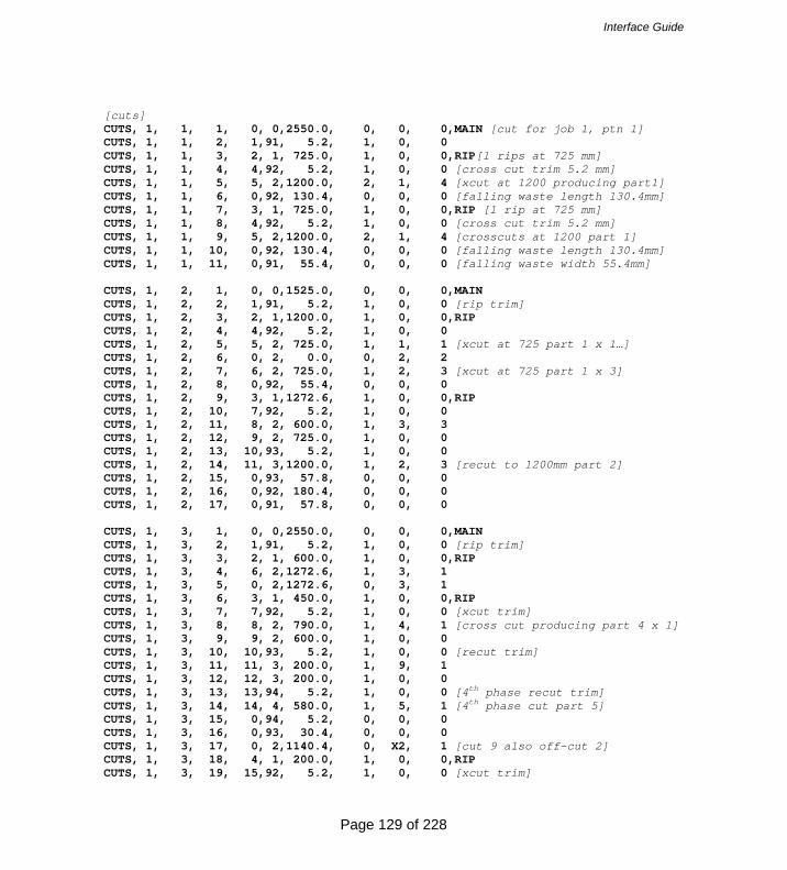
Interface Guide
Page 129 of 228
[cuts] CUTS, 1, 1, 1, 0, 0,2550.0, 0, 0, 0,MAIN [cut for job 1, ptn 1] CUTS, 1, 1, 2, 1,91, 5.2, 1, 0, 0 CUTS, 1, 1, 3, 2, 1, 725.0, 1, 0, 0,RIP[1 rips at 725 mm] CUTS, 1, 1, 4, 4,92, 5.2, 1, 0, 0 [cross cut trim 5.2 mm] CUTS, 1, 1, 5, 5, 2,1200.0, 2, 1, 4 [xcut at 1200 producing part1] CUTS, 1, 1, 6, 0,92, 130.4, 0, 0, 0 [falling waste length 130.4mm] CUTS, 1, 1, 7, 3, 1, 725.0, 1, 0, 0,RIP [1 rip at 725 mm] CUTS, 1, 1, 8, 4,92, 5.2, 1, 0, 0 [cross cut trim 5.2 mm] CUTS, 1, 1, 9, 5, 2,1200.0, 2, 1, 4 [crosscuts at 1200 part 1] CUTS, 1, 1, 10, 0,92, 130.4, 0, 0, 0 [falling waste length 130.4mm] CUTS, 1, 1, 11, 0,91, 55.4, 0, 0, 0 [falling waste width 55.4mm] CUTS, 1, 2, 1, 0, 0,1525.0, 0, 0, 0,MAIN CUTS, 1, 2, 2, 1,91, 5.2, 1, 0, 0 [rip trim] CUTS, 1, 2, 3, 2, 1,1200.0, 1, 0, 0,RIP CUTS, 1, 2, 4, 4,92, 5.2, 1, 0, 0 CUTS, 1, 2, 5, 5, 2, 725.0, 1, 1, 1 [xcut at 725 part 1 x 1…] CUTS, 1, 2, 6, 0, 2, 0.0, 0, 2, 2 CUTS, 1, 2, 7, 6, 2, 725.0, 1, 2, 3 [xcut at 725 part 1 x 3] CUTS, 1, 2, 8, 0,92, 55.4, 0, 0, 0 CUTS, 1, 2, 9, 3, 1,1272.6, 1, 0, 0,RIP CUTS, 1, 2, 10, 7,92, 5.2, 1, 0, 0 CUTS, 1, 2, 11, 8, 2, 600.0, 1, 3, 3 CUTS, 1, 2, 12, 9, 2, 725.0, 1, 0, 0 CUTS, 1, 2, 13, 10,93, 5.2, 1, 0, 0 CUTS, 1, 2, 14, 11, 3,1200.0, 1, 2, 3 [recut to 1200mm part 2] CUTS, 1, 2, 15, 0,93, 57.8, 0, 0, 0 CUTS, 1, 2, 16, 0,92, 180.4, 0, 0, 0 CUTS, 1, 2, 17, 0,91, 57.8, 0, 0, 0 CUTS, 1, 3, 1, 0, 0,2550.0, 0, 0, 0,MAIN CUTS, 1, 3, 2, 1,91, 5.2, 1, 0, 0 [rip trim] CUTS, 1, 3, 3, 2, 1, 600.0, 1, 0, 0,RIP CUTS, 1, 3, 4, 6, 2,1272.6, 1, 3, 1 CUTS, 1, 3, 5, 0, 2,1272.6, 0, 3, 1 CUTS, 1, 3, 6, 3, 1, 450.0, 1, 0, 0,RIP CUTS, 1, 3, 7, 7,92, 5.2, 1, 0, 0 [xcut trim] CUTS, 1, 3, 8, 8, 2, 790.0, 1, 4, 1 [cross cut producing part 4 x 1] CUTS, 1, 3, 9, 9, 2, 600.0, 1, 0, 0 CUTS, 1, 3, 10, 10,93, 5.2, 1, 0, 0 [recut trim] CUTS, 1, 3, 11, 11, 3, 200.0, 1, 9, 1 CUTS, 1, 3, 12, 12, 3, 200.0, 1, 0, 0 CUTS, 1, 3, 13, 13,94, 5.2, 1, 0, 0 [4th phase recut trim] CUTS, 1, 3, 14, 14, 4, 580.0, 1, 5, 1 [4th phase cut part 5] CUTS, 1, 3, 15, 0,94, 5.2, 0, 0, 0 CUTS, 1, 3, 16, 0,93, 30.4, 0, 0, 0 CUTS, 1, 3, 17, 0, 2,1140.4, 0, X2, 1 [cut 9 also off-cut 2] CUTS, 1, 3, 18, 4, 1, 200.0, 1, 0, 0,RIP CUTS, 1, 3, 19, 15,92, 5.2, 1, 0, 0 [xcut trim]

Interface Guide
Page 130 of 228
CUTS, 1, 3, 20, 16, 2, 580.0, 4, 5, 4 CUTS, 1, 3, 21, 0,92, 200.8, 0, 0, 0 CUTS, 1, 3, 22, 5, 1, 200.0, 1, 0, 0,RIP CUTS, 1, 3, 23, 15,92, 5.2, 1, 0, 0 CUTS, 1, 3, 24, 16, 2, 580.0, 4, 5, 4 CUTS, 1, 3, 25, 0,92, 200.8, 0, 0, 0 CUTS, 1, 3, 26, 0,91, 45.8, 0, 0, 0 CUTS, 1, 4, 1, 1, 0,2979.4, 1, 0, 0,MAIN CUTS, 1, 4, 2, 2,91, 5.2, 1, 0, 0 [rip trim] CUTS, 1, 4, 3, 3, 1, 600.0, 1, 0, 0,RIP CUTS, 1, 4, 4, 8,92, 5.2, 1, 0, 0 [xcut trim] CUTS, 1, 4, 5, 9, 2,1272.6, 2, 3, 2 [2 xcuts part 3 x 2] CUTS, 1, 4, 6, 11, 2, 200.0, 2, 9, 2 [2 xcuts producing part 9 x 2] CUTS, 1, 4, 7, 0,92, 5.0, 0, 0, 0 CUTS, 1, 4, 8, 4, 1, 450.0, 1, 0, 0,RIP CUTS, 1, 4, 9, 13,92, 5.2, 1, 0, 0 [xcut trim] CUTS, 1, 4, 10, 14, 2, 790.0, 3, 4, 3 [3 xcuts producing part 4 x 3] CUTS, 1, 4, 11, 17, 2, 580.0, 1, 0, 0 CUTS, 1, 4, 12, 18,93, 5.2, 1, 0, 0 [recut trim] CUTS, 1, 4, 13, 19, 3, 200.0, 2, 5, 2 [3rd phase cuts part 5 x 2] CUTS, 1, 4, 14, 0,93, 30.4, 0, 0, 0 CUTS, 1, 4, 15, 0,92, 0.2, 0, 0, 0 CUTS, 1, 4, 16, 5, 1, 200.0, 1, 0, 0,RIP [3 strips xcut together] CUTS, 1, 4, 17, 21,92, 5.2, 1, 0, 0 [xcut trim] CUTS, 1, 4, 18, 22, 2, 580.0, 3, 5, 3 [3 xcuts producing part 5 x 3] CUTS, 1, 4, 19, 25, 2, 600.0, 2, 9, 2 [2 xcuts producing part 9 x 2] CUTS, 1, 4, 20, 0,92, 5.4, 0, 0, 0 CUTS, 1, 4, 21, 6, 1, 200.0, 1, 0, 0,RIP CUTS, 1, 4, 22, 21,92, 5.2, 1, 0, 0 CUTS, 1, 4, 23, 22, 2, 580.0, 3, 5, 3 [xcuts with same sequence as record 18] CUTS, 1, 4, 24, 25, 2, 600.0, 2, 9, 2 [xcuts with same sequence as record 19] CUTS, 1, 4, 25, 0,92, 5.4, 0, 0, 0 CUTS, 1, 4, 26, 7, 1, 200.0, 1, 0, 0,RIP CUTS, 1, 4, 27, 21,92, 5.2, 1, 0, 0 CUTS, 1, 4, 28, 22, 2, 580.0, 3, 5, 3 [xcuts with same as record 18] CUTS, 1, 4, 29, 25, 2, 600.0, 2, 9, 2 [xcuts with same as record 18] CUTS, 1, 4, 30, 0,92, 5.4, 0, 0, 0 CUTS, 1, 4, 31, 0,91, 146.0, 0, 0, 0 CUTS, 1, 4, 32, 0, 0, 675.8, 0, X1, 1,HEAD [offcut produced] CUTS, 1, 5, 1, 1, 0,1415.0, 1, 0, 0,MAIN [head cut at 1415.0] CUTS, 1, 5, 2, 2,91, 5.2, 1, 0, 0 [rip trim] CUTS, 1, 5, 3, 3, 1, 300.0, 1, 0, 0,RIP [2 strips xcut together] CUTS, 1, 5, 4, 7,92, 5.2, 1, 0, 0

Interface Guide
Page 131 of 228
[xcut trim] CUTS, 1, 5, 5, 8, 2,1400.0, 1, 6, 2 CUTS, 1, 5, 6, 0,92, 0.2, 0, 0, 0 CUTS, 1, 5, 7, 4, 1, 300.0, 1, 0, 0,RIP CUTS, 1, 5, 8, 7,92, 5.2, 1, 0, 0 [xcut trim] CUTS, 1, 5, 9, 8, 2,1400.0, 1, 6, 2 CUTS, 1, 5, 10, 0,92, 0.2, 0, 0, 0 CUTS, 1, 5, 11, 5, 1, 275.0, 1, 0, 0,RIP [2 strips xcut together] CUTS, 1, 5, 12, 9,92, 5.2, 1, 0, 0 [xcut trim] CUTS, 1, 5, 13, 10, 2, 650.0, 2, 7, 4 CUTS, 1, 5, 14, 0,92, 95.4, 0, 0, 0 CUTS, 1, 5, 15, 6, 1, 275.0, 1, 0, 0,RIP CUTS, 1, 5, 16, 9,92, 5.2, 1, 0, 0 [xcut trim] CUTS, 1, 5, 17, 10, 2, 650.0, 2, 7, 4 CUTS, 1, 5, 18, 0,92, 95.4, 0, 0, 0 CUTS, 1, 5, 19, 0,91, 40.8, 0, 0, 0 CUTS, 1, 5, 20, 0, 0,1020.2, 0, 0, 0,HEAD [start of head section] CUTS, 1, 5, 21, 12,91, 5.2, 1, 0, 0 [rip trim] CUTS, 1, 5, 22, 13, 1, 650.0, 1, 0, 0,RIP CUTS, 1, 5, 23, 16,92, 0.2, 1, 0, 0 [xcut trim…head retrim - kerf] CUTS, 1, 5, 24, 17, 2, 275.0, 3, 7, 6 CUTS, 1, 5, 25, 0,92, 175.8, 0, 0, 0 CUTS, 1, 5, 26, 14, 1, 230.0, 1, 0, 0,RIP CUTS, 1, 5, 27, 20,92, 0.2, 1, 0, 0 CUTS, 1, 5, 28, 21, 2, 480.0, 2, 8, 4 CUTS, 1, 5, 29, 0,92, 45.6, 0, 0, 0 CUTS, 1, 5, 30, 15, 1, 230.0, 1, 0, 0,RIP CUTS, 1, 5, 31, 20,92, 0.2, 1, 0, 0 CUTS, 1, 5, 32, 21, 2, 480.0, 2, 8, 4 CUTS, 1, 5, 33, 0,92, 45.6, 0, 0, 0 CUTS, 1, 5, 34, 0,91, 85.6, 0, 0, 0 CUTS, 1, 6, 1, 1, 0,1464.6, 1, 0, 0,MAIN [head cut at 1464.6] CUTS, 1, 6, 2, 3,91, 5.2, 1, 0, 0 [rip trim] CUTS, 1, 6, 3, 4, 1, 300.0, 1, 0, 0,RIP [rip main 300 x 1] CUTS, 1, 6, 4, 8,92, 5.2, 1, 0, 0 [xcut trim] CUTS, 1, 6, 5, 9, 2,1400.0, 1, 6, 1 CUTS, 1, 6, 6, 0,92, 49.8, 0, 0, 0 CUTS, 1, 6, 7, 5, 1, 400.0, 1, 0, 0,RIP [3 strips xcut together] CUTS, 1, 6, 8, 10,92, 5.2, 1, 0, 0 [xcut trim] CUTS, 1, 6, 9, 11, 2, 480.0, 3, 10, 3 CUTS, 1, 6, 10, 0,92, 0.2, 0, 0, 0 CUTS, 1, 6, 11, 6, 1, 230.0, 1, 0, 0,RIP CUTS, 1, 6, 12, 10,92, 5.2, 1, 0, 0 CUTS, 1, 6, 13, 11, 2, 480.0, 3, 8, 3 CUTS, 1, 6, 14, 0,92, 0.2, 0, 0, 0 CUTS, 1, 6, 15, 7, 1, 230.0, 1, 0, 0,RIP CUTS, 1, 6, 16, 10,92, 5.2, 1, 0, 0

Interface Guide
Page 132 of 228
CUTS, 1, 6, 17, 11, 2, 480.0, 3, 8, 3 CUTS, 1, 6, 18, 0,92, 0.2, 0, 0, 0 CUTS, 1, 6, 19, 0,91, 30.8, 0, 0, 0 CUTS, 1, 6, 20, 2, 0, 480.0, 1, 0, 0,HEAD [head section] CUTS, 1, 6, 21, 14,91, 5.2, 1, 0, 0 [rip trim] CUTS, 1, 6, 22, 15, 1, 230.0, 5, 8, 5,RIP CUTS, 1, 6, 23, 0,91, 36.0, 0, 0, 0 CUTS, 1, 6, 24, 0, 0, 485.8, 0, 0, 0,HEAD CUTS, 1, 6, 25, 20,91, 5.2, 1, 0, 0 CUTS, 1, 6, 26, 21, 1, 480.0, 1, 0, 0,RIP [2 strips xcut together] CUTS, 1, 6, 27, 23, 2, 230.0, 2, 8, 2 CUTS, 1, 6, 28, 0,92, 16.2, 0, 0, 0 CUTS, 1, 6, 29, 22, 1, 480.0, 1, 0, 0,RIP [2 strips xcut together] CUTS, 1, 6, 30, 23, 2, 230.0, 2, 8, 2 CUTS, 1, 6, 31, 0,92, 16.2, 0, 0, 0 CUTS, 1, 6, 32, 0,91, 240.4, 0, 0, 0

Interface Guide
Page 133 of 228
19. EXAMPLES
Saw kerf: 4.8 Book Height: 2 Cycles: 1Rear trim (inc kerf) Rip: 10.0 Cross: 10.0 Retrim (inc kerf): 5.0
No Part Length Width Total Cut so Qty Qty Still Prod Far Brd Ptn To cut 1. P1 1200.0 725.0 9 NIL 4 8 1 ADR/PRG: [41] Cut Size Qty Part Cut Size Qty Part MAIN Trim 5.2 1 Trim 5.2 1 Cross cut 1200.0 2 P1 Rip 725.0 2 CUTS, 1, 1, 1, 0, 0,2550.0, 0, 0, 0,MAIN[cut record job 1, ptn 1] CUTS, 1, 1, 2, 1,91, 5.2, 1, 0, 0 CUTS, 1, 1, 3, 2, 1, 725.0, 1, 0, 0,RIP [1 rips at 725 mm] CUTS, 1, 1, 4, 4,92, 5.2, 1, 0, 0 [cross cut trim 5.2 mm] CUTS, 1, 1, 5, 5, 2,1200.0, 2, 1, 4 [xcut at 1200 producing part1] CUTS, 1, 1, 6, 0,92, 130.4, 0, 0, 0 [falling waste length 130.4mm]

Interface Guide
Page 134 of 228
CUTS, 1, 1, 7, 3, 1, 725.0, 1, 0, 0,RIP [1 rip at 725 mm] CUTS, 1, 1, 8, 4,92, 5.2, 1, 0, 0 [cross cut trim 5.2 mm] CUTS, 1, 1, 9, 5, 2,1200.0, 2, 1, 4 [crosscuts at 1200 part 1] CUTS, 1, 1, 10, 0,92, 130.4, 0, 0, 0 [falling waste length 130.4mm] CUTS, 1, 1, 11, 0,91, 55.4, 0, 0, 0 [falling waste width 55.4mm]
Saw kerf: 4.8 Book Height: 3 Cycles: 1Rear trim (inc kerf) Rip: 10.0 Cross: 10.0 Retrim (inc kerf): 5.0
No Part Length Width Total Cut so Qty Qty Still Prod Far Brd Ptn To cut 1. P1 1200.0 725.0 9 8 - 1 NIL 2. P2 1200.0 725.0 8 NIL - 8 NIL 3. P3 1272.6 600.0 7 NIL 1 3 4 ADR/PRG: [41] Cut Size Qty Part Cut Size Qty Part
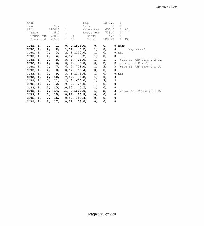
Interface Guide
Page 135 of 228
MAIN Rip 1272.6 1 Trim 5.2 1 Trim 5.2 1 Rip 1200.0 1 Cross cut 600.0 1 P3 Trim 5.2 1 Cross cut 725.0 1 Cross cut 725.0 1 P1 Recut 5.2 1 Cross cut 725.0 1 P2 Recut 1200.0 1 P2 CUTS, 1, 2, 1, 0, 0,1525.0, 0, 0, 0,MAIN CUTS, 1, 2, 2, 1,91, 5.2, 1, 0, 0 [rip trim] CUTS, 1, 2, 3, 2, 1,1200.0, 1, 0, 0,RIP CUTS, 1, 2, 4, 4,92, 5.2, 1, 0, 0 CUTS, 1, 2, 5, 5, 2, 725.0, 1, 1, 1 [xcut at 725 part 1 x 1… CUTS, 1, 2, 6, 0, 2, 0.0, 0, 2, 2 … and part 2 x 2] CUTS, 1, 2, 7, 6, 2, 725.0, 1, 2, 3 [xcut at 725 part 2 x 3] CUTS, 1, 2, 8, 0,92, 55.4, 0, 0, 0 CUTS, 1, 2, 9, 3, 1,1272.6, 1, 0, 0,RIP CUTS, 1, 2, 10, 7,92, 5.2, 1, 0, 0 CUTS, 1, 2, 11, 8, 2, 600.0, 1, 3, 3 CUTS, 1, 2, 12, 9, 2, 725.0, 1, 0, 0 CUTS, 1, 2, 13, 10,93, 5.2, 1, 0, 0 CUTS, 1, 2, 14, 11, 3,1200.0, 1, 2, 3 [recut to 1200mm part 2] CUTS, 1, 2, 15, 0,93, 57.8, 0, 0, 0 CUTS, 1, 2, 16, 0,92, 180.4, 0, 0, 0 CUTS, 1, 2, 17, 0,91, 57.8, 0, 0, 0

Interface Guide
Page 136 of 228
No Part Length Width Total Cut so Qty Qty Still Prod Far Brd Ptn To cut 3. P3 1272.6 600.0 7 3 2 2 2 4. P4 790.0 450.0 4 NIL 1 1 3 5. P5 580.0 200.0 20 NIL 9 9 11 9. P9 600.0 200.0 7 NIL 1 1 8 ADR/PRG: [41] Cut Size Qty Part Cut Size Qty Part MAIN Recut 5.2 1 Trim 5.2 1 Recut 200.0 1 P9 Rip 600.0 1 Recut 200.0 1 Cross cut 1250.0 1 P3 Recut 5.2 1 P3 Recut 580.0 1 P5 Rip 450.0 1 Rip 200.0 2 Trim 5.2 1 Trim 5.2 1 Cross cut 790.0 1 P4 Cross cut 580.0 4 P5 Cross cut 630.0 1 CUTS, 1, 3, 1, 0, 0,2550.0, 0, 0, 0,MAIN CUTS, 1, 3, 2, 1,91, 5.2, 1, 0, 0 [rip trim] CUTS, 1, 3, 3, 2, 1, 600.0, 1, 0, 0,RIP

Interface Guide
Page 137 of 228
CUTS, 1, 3, 4, 6, 2,1272.6, 1, 3, 1 CUTS, 1, 3, 5, 0, 2,1272.6, 0, 3, 1 CUTS, 1, 3, 6, 3, 1, 450.0, 1, 0, 0,RIP CUTS, 1, 3, 7, 7,92, 5.2, 1, 0, 0 [xcut trim] CUTS, 1, 3, 8, 8, 2, 790.0, 1, 4, 1 [cross cut part 4 x 1] CUTS, 1, 3, 9, 9, 2, 600.0, 1, 0, 0 CUTS, 1, 3, 10, 10,93, 5.2, 1, 0, 0 [recut trim] CUTS, 1, 3, 11, 11, 3, 200.0, 1, 9, 1 CUTS, 1, 3, 12, 12, 3, 200.0, 1, 0, 0 CUTS, 1, 3, 13, 13,94, 5.2, 1, 0, 0 [4th phase recut trim] CUTS, 1, 3, 14, 14, 4, 580.0, 1, 5, 1 [4th phase cut part 5] CUTS, 1, 3, 15, 0,94, 5.2, 0, 0, 0 CUTS, 1, 3, 16, 0,93, 30.4, 0, 0, 0 CUTS, 1, 3, 17, 0, 2,1140.4, 0, X2, 1 [cut 9 also off-cut 2] CUTS, 1, 3, 18, 4, 1, 200.0, 1, 0, 0,RIP CUTS, 1, 3, 19, 15,92, 5.2, 1, 0, 0 [xcut trim] CUTS, 1, 3, 20, 16, 2, 580.0, 4, 5, 4 CUTS, 1, 3, 21, 0,92, 200.8, 0, 0, 0 CUTS, 1, 3, 22, 5, 1, 200.0, 1, 0, 0,RIP CUTS, 1, 3, 23, 15,92, 5.2, 1, 0, 0 CUTS, 1, 3, 24, 16, 2, 580.0, 4, 5, 4 CUTS, 1, 3, 25, 0,92, 200.8, 0, 0, 0 CUTS, 1, 3, 26, 0,91, 45.8, 0, 0, 0

Interface Guide
Page 138 of 228
No Part Length Width Total Cut so Qty Qty Still Prod Far Brd Ptn To cut 3. P3 1272.6 600.0 7 5 2 2 NIL 4. P4 790.0 450.0 4 1 3 3 NIL 5. P5 580.0 200.0 20 9 11 11 NIL 9. P9 600.0 200.0 7 1 8 8 NIL ADR/PRG: [41] Cut Size Qty Part Cut Size Qty Part Head cut 2979.4 1 Cross cut 790.0 3 P4 MAIN Cross cut 580.0 1 Trim 5.2 1 Recut 5.2 1 Rip 600.0 1 Recut 200.0 2 P5 Trim 5.2 1 Rip 200.0 3 Cross cut 1272.6 2 P3 Trim 5.2 1 Cross cut 200.0 2 P9 Cross cut 580.0 3 P5 Rip 450.0 1 Cross cut 630.0 2 P9 Trim 5.2 1 CUTS, 1, 4, 1, 1, 0,2979.4, 1, 0, 0,MAIN CUTS, 1, 4, 2, 2,91, 5.2, 1, 0, 0 [rip trim] CUTS, 1, 4, 3, 3, 1, 600.0, 1, 0, 0,RIP CUTS, 1, 4, 4, 8,92, 5.2, 1, 0, 0 [xcut trim]
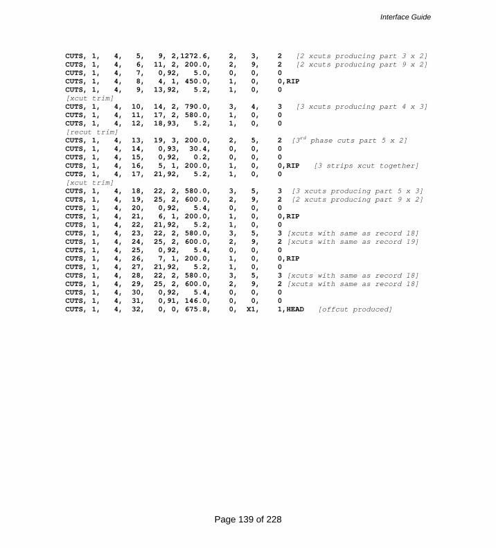
Interface Guide
Page 139 of 228
CUTS, 1, 4, 5, 9, 2,1272.6, 2, 3, 2 [2 xcuts producing part 3 x 2] CUTS, 1, 4, 6, 11, 2, 200.0, 2, 9, 2 [2 xcuts producing part 9 x 2] CUTS, 1, 4, 7, 0,92, 5.0, 0, 0, 0 CUTS, 1, 4, 8, 4, 1, 450.0, 1, 0, 0,RIP CUTS, 1, 4, 9, 13,92, 5.2, 1, 0, 0 [xcut trim] CUTS, 1, 4, 10, 14, 2, 790.0, 3, 4, 3 [3 xcuts producing part 4 x 3] CUTS, 1, 4, 11, 17, 2, 580.0, 1, 0, 0 CUTS, 1, 4, 12, 18,93, 5.2, 1, 0, 0 [recut trim] CUTS, 1, 4, 13, 19, 3, 200.0, 2, 5, 2 [3rd phase cuts part 5 x 2] CUTS, 1, 4, 14, 0,93, 30.4, 0, 0, 0 CUTS, 1, 4, 15, 0,92, 0.2, 0, 0, 0 CUTS, 1, 4, 16, 5, 1, 200.0, 1, 0, 0,RIP [3 strips xcut together] CUTS, 1, 4, 17, 21,92, 5.2, 1, 0, 0 [xcut trim] CUTS, 1, 4, 18, 22, 2, 580.0, 3, 5, 3 [3 xcuts producing part 5 x 3] CUTS, 1, 4, 19, 25, 2, 600.0, 2, 9, 2 [2 xcuts producing part 9 x 2] CUTS, 1, 4, 20, 0,92, 5.4, 0, 0, 0 CUTS, 1, 4, 21, 6, 1, 200.0, 1, 0, 0,RIP CUTS, 1, 4, 22, 21,92, 5.2, 1, 0, 0 CUTS, 1, 4, 23, 22, 2, 580.0, 3, 5, 3 [xcuts with same as record 18] CUTS, 1, 4, 24, 25, 2, 600.0, 2, 9, 2 [xcuts with same as record 19] CUTS, 1, 4, 25, 0,92, 5.4, 0, 0, 0 CUTS, 1, 4, 26, 7, 1, 200.0, 1, 0, 0,RIP CUTS, 1, 4, 27, 21,92, 5.2, 1, 0, 0 CUTS, 1, 4, 28, 22, 2, 580.0, 3, 5, 3 [xcuts with same as record 18] CUTS, 1, 4, 29, 25, 2, 600.0, 2, 9, 2 [xcuts with same as record 18] CUTS, 1, 4, 30, 0,92, 5.4, 0, 0, 0 CUTS, 1, 4, 31, 0,91, 146.0, 0, 0, 0 CUTS, 1, 4, 32, 0, 0, 675.8, 0, X1, 1,HEAD [offcut produced]

Interface Guide
Page 140 of 228
Saw kerf: 4.8 Book Height: 2 Cycles: 1Rear trim (inc kerf) Rip: 10.0 Cross: 10.0 Retrim (inc kerf): 5.0
No Part Length Width Total Cut so Qty Qty Still Prod Far Brd Ptn To cut 6. P6 1400.0 300.0 5 NIL 2 4 1 7. P7 650.0 275.0 14 NIL 7 14 NIL 8. P8 480.0 230.0 23 NIL 4 8 15 ADR/PRG: [41] Cut Size Qty Part Cut Size Qty Part Head cut 1415.0 1 HEAD 1 MAIN Trim 5.2 1 Trim 5.2 1 Rip 650.0 1 Rip 300.0 2 Trim 0.2 1 Trim 5.2 1 Cross cut 275.0 3 P7 Cross cut 1400.0 1 P6 Rip 230.0 2 Rip 275.0 2 Trim 0.2 1 Trim 5.2 1 Cross cut 480.0 2 P8 Cross cut 650.0 2 P7 CUTS, 1, 5, 1, 1, 0,1415.0, 1, 0, 0,MAIN [head cut at 1415.0] CUTS, 1, 5, 2, 2,91, 5.2, 1, 0, 0 [rip trim] CUTS, 1, 5, 3, 3, 1, 300.0, 1, 0, 0,RIP [2 strips xcut together] CUTS, 1, 5, 4, 7,92, 5.2, 1, 0, 0 [xcut trim]
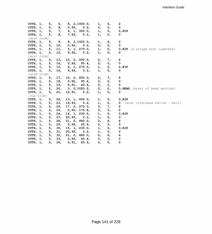
Interface Guide
Page 141 of 228
CUTS, 1, 5, 5, 8, 2,1400.0, 1, 6, 2 CUTS, 1, 5, 6, 0,92, 0.2, 0, 0, 0 CUTS, 1, 5, 7, 4, 1, 300.0, 1, 0, 0,RIP CUTS, 1, 5, 8, 7,92, 5.2, 1, 0, 0 [xcut trim] CUTS, 1, 5, 9, 8, 2,1400.0, 1, 6, 2 CUTS, 1, 5, 10, 0,92, 0.2, 0, 0, 0 CUTS, 1, 5, 11, 5, 1, 275.0, 1, 0, 0,RIP [2 strips xcut together] CUTS, 1, 5, 12, 9,92, 5.2, 1, 0, 0 [xcut trim] CUTS, 1, 5, 13, 10, 2, 650.0, 2, 7, 4 CUTS, 1, 5, 14, 0,92, 95.4, 0, 0, 0 CUTS, 1, 5, 15, 6, 1, 275.0, 1, 0, 0,RIP CUTS, 1, 5, 16, 9,92, 5.2, 1, 0, 0 [xcut trim] CUTS, 1, 5, 17, 10, 2, 650.0, 2, 7, 4 CUTS, 1, 5, 18, 0,92, 95.4, 0, 0, 0 CUTS, 1, 5, 19, 0,91, 40.8, 0, 0, 0 CUTS, 1, 5, 20, 0, 0,1020.2, 0, 0, 0,HEAD [start of head section] CUTS, 1, 5, 21, 12,91, 5.2, 1, 0, 0 [rip trim] CUTS, 1, 5, 22, 13, 1, 650.0, 1, 0, 0,RIP CUTS, 1, 5, 23, 16,92, 0.2, 1, 0, 0 [xcut trim…head retrim - kerf] CUTS, 1, 5, 24, 17, 2, 275.0, 3, 7, 6 CUTS, 1, 5, 25, 0,92, 175.8, 0, 0, 0 CUTS, 1, 5, 26, 14, 1, 230.0, 1, 0, 0,RIP CUTS, 1, 5, 27, 20,92, 0.2, 1, 0, 0 CUTS, 1, 5, 28, 21, 2, 480.0, 2, 8, 4 CUTS, 1, 5, 29, 0,92, 45.6, 0, 0, 0 CUTS, 1, 5, 30, 15, 1, 230.0, 1, 0, 0,RIP CUTS, 1, 5, 31, 20,92, 0.2, 1, 0, 0 CUTS, 1, 5, 32, 21, 2, 480.0, 2, 8, 4 CUTS, 1, 5, 33, 0,92, 45.6, 0, 0, 0 CUTS, 1, 5, 34, 0,91, 85.6, 0, 0, 0

Interface Guide
Page 142 of 228
Saw kerf: 4.8 Book Height: 1 Cycles: 1Rear trim (inc kerf) Rip: 10.0 Cross: 10.0 Retrim (inc kerf): 5.0
No Part Length Width Total Cut so Qty Qty Still Prod Far Brd Ptn To cut 6. P6 1400.0 300.0 5 4 1 1 NIL 8. P8 480.0 230.0 23 8 15 15 NIL 10. P10 480.0 400.0 3 NIL 3 3 NIL ADR/PRG: [41] Cut Size Qty Part Cut Size Qty Part Head cut 1464.6 1 Cross cut 480.0 3 P8 MAIN Head cut 480.0 1 Trim 5.2 1 HEAD 1 Rip 300.0 1 Trim 5.2 1 Trim 5.2 1 Rip 230.0 5 P8 Cross cut 1400.0 1 P6 HEAD 2 Rip 400.0 1 Trim 5.2 1 Trim 5.2 1 Rip 480.0 2 Cross cut 480.0 3 P10 Cross cut 230.0 2 P8
Rip 230.0 2
Trim 5.2 1 CUTS, 1, 6, 1, 1, 0,1464.6, 1, 0, 0,MAIN [head cut at 1464.6] CUTS, 1, 6, 2, 3,91, 5.2, 1, 0, 0 [rip trim]
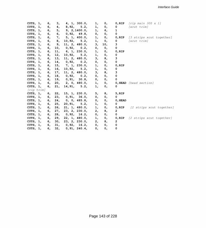
Interface Guide
Page 143 of 228
CUTS, 1, 6, 3, 4, 1, 300.0, 1, 0, 0,RIP [rip main 300 x 1] CUTS, 1, 6, 4, 8,92, 5.2, 1, 0, 0 [xcut trim] CUTS, 1, 6, 5, 9, 2,1400.0, 1, 6, 1 CUTS, 1, 6, 6, 0,92, 49.8, 0, 0, 0 CUTS, 1, 6, 7, 5, 1, 400.0, 1, 0, 0,RIP [3 strips xcut together] CUTS, 1, 6, 8, 10,92, 5.2, 1, 0, 0 [xcut trim] CUTS, 1, 6, 9, 11, 2, 480.0, 3, 10, 3 CUTS, 1, 6, 10, 0,92, 0.2, 0, 0, 0 CUTS, 1, 6, 11, 6, 1, 230.0, 1, 0, 0,RIP CUTS, 1, 6, 12, 10,92, 5.2, 1, 0, 0 CUTS, 1, 6, 13, 11, 2, 480.0, 3, 8, 3 CUTS, 1, 6, 14, 0,92, 0.2, 0, 0, 0 CUTS, 1, 6, 15, 7, 1, 230.0, 1, 0, 0,RIP CUTS, 1, 6, 16, 10,92, 5.2, 1, 0, 0 CUTS, 1, 6, 17, 11, 2, 480.0, 3, 8, 3 CUTS, 1, 6, 18, 0,92, 0.2, 0, 0, 0 CUTS, 1, 6, 19, 0,91, 30.8, 0, 0, 0 CUTS, 1, 6, 20, 2, 0, 480.0, 1, 0, 0,HEAD [head section] CUTS, 1, 6, 21, 14,91, 5.2, 1, 0, 0 [rip trim] CUTS, 1, 6, 22, 15, 1, 230.0, 5, 8, 5,RIP CUTS, 1, 6, 23, 0,91, 36.0, 0, 0, 0 CUTS, 1, 6, 24, 0, 0, 485.8, 0, 0, 0,HEAD CUTS, 1, 6, 25, 20,91, 5.2, 1, 0, 0 CUTS, 1, 6, 26, 21, 1, 480.0, 1, 0, 0,RIP [2 strips xcut together] CUTS, 1, 6, 27, 23, 2, 230.0, 2, 8, 2 CUTS, 1, 6, 28, 0,92, 16.2, 0, 0, 0 CUTS, 1, 6, 29, 22, 1, 480.0, 1, 0, 0,RIP [2 strips xcut together] CUTS, 1, 6, 30, 23, 2, 230.0, 2, 8, 2 CUTS, 1, 6, 31, 0,92, 16.2, 0, 0, 0 CUTS, 1, 6, 32, 0,91, 240.4, 0, 0, 0

Interface Guide
Page 144 of 228
20. SUMMARY OF DATA STRUCTURE This section summarises the position and format of each field in each record type. The maximum length of each text field is listed in the comment column. The range of acceptable values for other field types is listed where applicable. Please refer to earlier comments for a fuller explanation of fields. Each field can be categorised by one of the following types. DIM Dimension. Number single. When working in millimetres these range from 0.0 to 9999.9. When
working in decimal inches dimensions must range from 0.000 to 999.9 FLT Number single. Floating point value. IDX Index. Number integer. These are integer values which are used to link records. For example all data
for a particular job must have the same job index. INT Number integer. QTY A long integer used to store quantity. No quantity can be greater than 99999. TXT A text field used to store information Note that spaces are not allowed in the material code, and any spaces will be converted to an underscore (‘_’) on import. Also note that material, part and board codes are converted to upper case on import.
The job records must have unique job index numbers starting at 1, and incrementing consecutively within specified range. The part, board and pattern records must each have their respective index numbers unique within the job, and again be numbered from 1 and incremented consecutively.
'HEADER' RECORD No. Name Description Type Comment MDB 1 VERSION File version TXT Set to 1.06 Text 2 TITLE File title TXT 25 chars max. Text 3 UNITS Measurement mode INT 0,1 Number-Integer 4 ORIGIN Pattern origin INT 0-3 Number-Integer 5 TRIM_TYPE Fixed trim front or rear? INT 0,1 Number-Integer 'JOBS' RECORD No. Name Description Typ
e Comment MDB
1 JOB_INDEX Job index IDX 1-250 Number-Integer 2 NAME Job number/name TXT 50 chars max. Text 3 DESC Job description TXT 50 chars max Text 4 ORD_DATE Date of order TXT DD/MM/YYYY 5 CUT_DATE Date for cutting TXT DD/MM/YYYY 6 CUSTOMER Customer code TXT 100 chars max. Text 7 STATUS Job status INT 0,1,2 Number- Integer 8 OPT_PARAM Optimising parameters TXT 50 chars max. Text 9 SAW_PARAM Saw parameters TXT 50 chars max. Text 10 CUT_TIME Total cut time INT Number-Long Int 11 WASTE_PCNT Waste percentage FLT Number-Single

Interface Guide
Page 145 of 228
'PARTS_REQ' RECORD No.
Name Description Type
Comment MDB
1 JOB_INDEX Job index IDX 1-250 Number- Integer 2 PART_INDEX Part index IDX 1-9999 Number- Integer 3 CODE Part code TXT 50 chrs max Text 4 MAT_INDEX Material index IDX 1-9999 Number- Integer 5 LENGTH Part length DIM Number-Single 6 WIDTH Part width DIM Number-Single 7 QTY_REQ Number of pieces QTY Max 99999 Number-Long Int 8 QTY_OVER Max over production QTY Max 99999 Number-Long Int 9 QTY_UNDER Max under production QTY Max 99999 Number-Long Int 10 GRAIN Grain INT 0,1,2 Number-Integer 11 QTY_PROD Num pieces produced QTY Max 99999 Number-Long Int 12 UNDER_PROD_ERROR Num pieces under
produced because of an error
QTY Max 99999 Number-Long Int
13 UNDER_PROD_ALLOWED Num pieces under produced because of allowed unders
QTY Max 99999 Number-Long Int
14 UNDER_PROD_PLUSPART Num plus part pieces under produced
QTY Max 99999 Number-Long Int
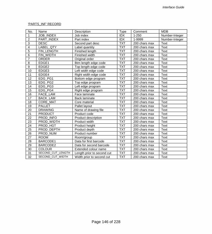
Interface Guide
Page 146 of 228
'PARTS_INF' RECORD No. Name Description Type Comment MDB 1 JOB_INDEX Job index IDX 1-250 Number-Integer 2 PART_INDEX Part index IDX 1-9999 Number-Integer 3 DESC Second part desc TXT 200 chars max Text 4 LABEL_QTY Label quantity TXT 200 chars max Text 5 FIN_LENGTH Finished length TXT 200 chars max Text 6 FIN_WIDTH Finished width TXT 200 chars max Text 7 ORDER Original order TXT 200 chars max Text 8 EDGE1 Btm length edge code TXT 200 chars max Text 9 EDGE2 Top length edge code TXT 200 chars max Text 10 EDGE3 Left width edge code TXT 200 chars max Text 11 EDGE4 Right width edge code TXT 200 chars max Text 12 EDG_PG1 Bottom edge program TXT 200 chars max Text 13 EDG_PG2 Top edge program TXT 200 chars max Text 14 EDG_PG3 Left edge program TXT 200 chars max Text 15 EDG_PG4 Right edge program TXT 200 chars max Text 16 FACE_LAM Face laminate TXT 200 chars max Text 17 BACK_LAM Back laminate TXT 200 chars max Text 18 CORE_MAT Core material TXT 200 chars max Text 19 PALLET Pallet layout TXT 200 chars max Text 20 DRAWING Name of drawing file TXT 200 chars max Text 21 PRODUCT Product code TXT 200 chars max Text 22 PROD_INFO Product description TXT 200 chars max Text 23 PROD_WIDTH Product width TXT 200 chars max Text 24 PROD_HGT Product height TXT 200 chars max Text 25 PROD_DEPTH Product depth TXT 200 chars max Text 26 PROD_NUM Product number TXT 200 chars max Text 27 ROOM Room/group TXT 200 chars max Text 28 BARCODE1 Data for first barcode TXT 200 chars max Text 29 BARCODE2 Data for second barcode TXT 200 chars max Text 30 COLOUR Extended colour name TXT 200 chars max Text 31 SECOND_CUT_LENGTH Length prior to second cut TXT 200 chars max Text 32 SECOND_CUT_WIDTH Width prior to second cut TXT 200 chars max Text

Interface Guide
Page 147 of 228
'PARTS_UDI' RECORD No. Name Description Typ
e Comment MDB
1 JOB_INDEX Job index IDX 1-250 Number-Integer 2 PART_INDEX Part index IDX 1-9999 Number-Integer 3 INFO1 Information field 1 TXT 200 chars max Text 4 INFO2 Information field 2 TXT 200 chars max Text 5 INFO3 Information field 3 TXT 200 chars max Text 6 INFO4 Information field 4 TXT 200 chars max Text 7 INFO5 Information field 5 TXT 200 chars max Text 8 INFO6 Information field 6 TXT 200 chars max Text 9 INFO7 Information field 7 TXT 200 chars max Text 10 INFO8 Information field 8 TXT 200 chars max Text 11 INFO9 Information field 9 TXT 200 chars max Text 12 INFO10 Information field 10 TXT 200 chars max Text 13 INFO11 Information field 11 TXT 200 chars max Text 14 INFO12 Information field 12 TXT 200 chars max Text 15 INFO13 Information field 13 TXT 200 chars max Text 16 INFO14 Information field 14 TXT 200 chars max Text 17 INFO15 Information field 15 TXT 200 chars max Text 18 INFO16 Information field 16 TXT 200 chars max Text 19 INFO17 Information field 17 TXT 200 chars max Text 20 INFO18 Information field 18 TXT 200 chars max Text 21 INFO19 Information field 19 TXT 200 chars max Text 22 INFO20 Information field 20 TXT 200 chars max Text 23 INFO21 Information field 21 TXT 200 chars max Text 24 INFO22 Information field 22 TXT 200 chars max Text 25 INFO23 Information field 23 TXT 200 chars max Text 26 INFO24 Information field 24 TXT 200 chars max Text 27 INFO25 Information field 25 TXT 200 chars max Text 28 INFO26 Information field 26 TXT 200 chars max Text 29 INFO27 Information field 27 TXT 200 chars max Text 30 INFO28 Information field 28 TXT 200 chars max Text 31 INFO29 Information field 29 TXT 200 chars max Text 32 INFO30 Information field 30 TXT 200 chars max Text 33 INFO31 Information field 31 TXT 200 chars max Text 34 INFO32 Information field 32 TXT 200 chars max Text 35 INFO33 Information field 33 TXT 200 chars max Text 36 INFO34 Information field 34 TXT 200 chars max Text 37 INFO35 Information field 35 TXT 200 chars max Text 38 INFO36 Information field 36 TXT 200 chars max Text 39 INFO37 Information field 37 TXT 200 chars max Text 40 INFO38 Information field 38 TXT 200 chars max Text 41 INFO39 Information field 39 TXT 200 chars max Text 42 INFO40 Information field 40 TXT 200 chars max Text 43 INFO41 Information field 41 TXT 200 chars max Text 44 INFO42 Information field 42 TXT 200 chars max Text

Interface Guide
Page 148 of 228
45 INFO43 Information field 43 TXT 200 chars max Text 'PARTS_UDI' RECORD (continued) 46 INFO44 Information field 44 TXT 200 chars max Text 47 INFO45 Information field 45 TXT 200 chars max Text 48 INFO46 Information field 46 TXT 200 chars max Text 49 INFO47 Information field 47 TXT 200 chars max Text 50 INFO48 Information field 48 TXT 200 chars max Text 51 INFO49 Information field 49 TXT 200 chars max Text 52 INFO50 Information field 50 TXT 200 chars max Text 53 INFO51 Information field 51 TXT 200 chars max Text 54 INFO52 Information field 52 TXT 200 chars max Text 55 INFO53 Information field 53 TXT 200 chars max Text 56 INFO54 Information field 54 TXT 200 chars max Text 57 INFO55 Information field 55 TXT 200 chars max Text 58 INFO56 Information field 56 TXT 200 chars max Text 59 INFO57 Information field 57 TXT 200 chars max Text 60 INFO58 Information field 58 TXT 200 chars max Text 61 INFO59 Information field 59 TXT 200 chars max Text 62 INFO60 Information field 60 TXT 200 chars max Text

Interface Guide
Page 149 of 228
'PARTS_DST' RECORD No. Name Description Type Comment MDB 1 JOB_INDEX Job index IDX 1-250 Number-Integer 2 PART_INDEX Part index IDX 1-9999 Number-Integer 3 PART_LAY_L Parts per stack length INT 1-99 Number-Integer 4 PART_LAY_W Parts per stack width INT 1-99 Number-Integer 5 PART_LAY_O Part orientation INT 0,1 (0=rotated) Number-Integer 6 STK_HGHT_Q Stack height - pieces INT 0-999 Number-Integer 7 STK_HGHT_D Stack height - dim INT 0-9999 Number-Integer 8 STATION Station number INT 0-99 Number-Integer 9 QTY_STACKS Total number of stacks QTY Max 99999 Number-Long Int 10 BTM_TYPE Bottom destack type INT 0,1,2,3,4 Number-Integer 11 BTM_DESC Bottom description TXT 25 chars max Text 12 BTM_MATL Bottom material TXT 25 chars max Text 13 BTM_LENGTH Baseboard/pallet len DIM Number-Single 14 BTM_WIDTH Baseboard/pallet wid DIM Number-Single 15 BTM_THICK Baseboard/pallet thk DIM Number-Single 16 OVER_LEN Overhang/oversize DIM Number-Single 17 OVER_WID Overhang/oversize DIM Number-Single 18 BTM_LAY_L Bsb/pallets per length INT 0-99 Number-Integer 19 BTM_LAY_W Bsb/pallets per width INT 0-99 Number-Integer 20 TOP_TYPE Top destack type INT 0,1,2,3,4 Number-Integer 21 TOP_DESC Top description TXT 25 chars max Text 22 TOP_MATL Top material TXT 25 chars max Text 23 TOP_LENGTH Baseboard length DIM Number-Single 24 TOP_WIDTH Baseboard width DIM Number-Single 25 TOP_THICK Baseboard thk DIM Number-Single 26 TOP_LAY_L Baseboards per length INT 0-99 Number-Integer 27 TOP_LAY_W Baseboards per width INT 0-99 Number-Integer 28 SUP_TYPE Support destack type INT 0,1,2,3,4 Number-Integer 29 SUP_DESC Support description TXT 25 chars max Text 30 SUP_MATL Support material TXT 25 chars max Text 31 SUP_LENGTH Support length DIM Number-Single 32 SUP_WIDTH Support width DIM Number-Single 33 SUP_THICK Support thickness DIM Number-Single 34 SUP_LAY_L Supports length INT 0-99 Number-Integer 35 SUP_LAY_W Supports per width INT 0-99 Number-Integer 36 STATION2 Alternative station INT 0-99 Number-Integer

Interface Guide
Page 150 of 228
'BOARDS' RECORD No. Name Description Type Comment MDB 1 JOB_INDEX Job index IDX 1-250 Number-Integer 2 BRD_INDEX Board index IDX 1-5000 Number-Integer 3 CODE Board code TXT 50 chars max Text 4 MAT_INDEX Material index IDX 1-9999 Number-Integer 5 LENGTH Board length DIM Number-Single 6 WIDTH Board width DIM Number-Single 7 QTY_STOCK Number of sheets QTY Max 99999 Number-Long Int 8 QTY_USED Number of sheets used QTY Max 99999 Number-Long Int 9 COST Cost per sq metre/foot FLT 0-9.99 Number-Single 10 STK_FLAG Board limit/ratio INT 0-9 Number-Integer 11 INFORMATION Board information TXT 50 chars max Text 12 MAT_PARAM Parameter file name TXT 50 max chars Text 13 GRAIN Grain INT 0,1,2 Number-Integer 14 TYPE Type INT 0,1 Number-Integer 15 BIN Board location TXT 25 chars max Text 16 SUPPLIER Board suppler TXT 50 chars max Text 'MATERIALS' RECORD No. Name Description Type Comment MDB 1 JOB_INDEX Job index IDX 1-250 Number-Integer 2 MAT_INDEX Material index IDX 1-9999 Number-Integer 3 CODE Material code TXT 50 chars max Text 4 DESC Material description TXT 50 chars max Text 5 THICK Material thickness DIM Number-Single 6 BOOK Max sheets per book QTY Number-Long Int 7 KERF_RIP Saw kerf (rip) DIM Number-Single 8 KERF_XCT Saw kerf (crosscut) DIM Number-Single 9 TRIM_FRIP Fixed rip trim DIM Number-Single 10 TRIM_VRIP Min waste rip trim DIM Number-Single 11 TRIM_FXCT Fixed crosscut trim DIM Number-Single 12 TRIM_VXCT Min waste crosscut trim DIM Number-Single 13 TRIM_HEAD Internal Head trim DIM Number-Single 14 TRIM_FRCT Fixed recut trim DIM Number-Single 15 TRIM_VRCT Min waste recut trim DIM Number-Single 16 RULE1 Optimising rule 1 INT 1-9 Number-Integer 17 RULE2 Optimising rule 2 INT 0,1 Number-Integer 18 RULE3 Optimising rule 3 INT 0,1 Number-Integer 19 RULE4 Optimising rule 4 INT 0,1 Number-Integer 20 MAT_PARAM Parameter file name TXT 50 max chars Text 21 GRAIN Grain INT 0,1,2 Number-Integer 22 PICTURE RGB colour or picture file name TXT 100 chars max Text 23 DENSITY Material density FLT 0-99.999 Number-Single

Interface Guide
Page 151 of 228
'OFFCUTS' RECORD No. Name Description Type Comment MDB 1 JOB_INDEX Job index IDX 1-250 Number-Integer 2 OFC_INDEX Offcut index IDX 1-7500 Number-Integer 3 CODE Offcut code TXT 50 chars max Text 4 MAT_INDEX Material index IDX 1-9999 Number-Integer 5 LENGTH Offcut length DIM Number-Single 6 WIDTH Offcut width DIM Number-Single 7 OFC_QTY Offcut quantity QTY Max 99999 Number-Long Int 'PATTERNS' RECORD No. Name Description Type Comment MDB 1 JOB_INDEX Job index IDX 1-250 Number-Integer 2 PTN_INDEX Pattern index IDX 1-5000 Number-Integer 3 BRD_INDEX Board index IDX 1-5000 Number-Integer 4 TYPE Pattern type INT 0-8 Number-Integer 5 QTY_RUN Run quantity QTY Number-Long Int 6 QTY_CYCLES Cycle quantity QTY Number-Long Int 7 MAX_BOOK Max sheets per book QTY Number-Long Int 8 PICTURE Pattern picture file TXT 255 chrs max Text 9 CYCLE_TIME Cycle cut time INT Number-Long Int 10 TOTAL_TIME Total cut time INT Number-Long Int 'PTN_UDI' RECORD No. Name Description Type Comment MDB 1 JOB_INDEX Job index IDX 1-250 Number-Integer 2 PTN_INDEX Pattern index IDX 1-5000 Number-Integer 3 BRD_INDEX Board index IDX 1-5000 Number-Integer 4 STRIP_INDEX Strip number INT Number-Integer 5 INFO1 Information field 1 TXT 200 chars max Text 6 INFO2 Information field 2 TXT 200 chars max Text 7 INFO3 Information field 3 TXT 200 chars max Text 8 INFO4 Information field 4 TXT 200 chars max Text 9 INFO5 Information field 5 TXT 200 chars max Text 10 INFO6 Information field 6 TXT 200 chars max Text 11 INFO7 Information field 7 TXT 200 chars max Text 12 INFO8 Information field 8 TXT 200 chars max Text 13 INFO9 Information field 9 TXT 200 chars max Text 14 INFO10 Information field 10 TXT 200 chars max Text 15 INFO11 Information field 11 TXT 200 chars max Text 16 INFO12 Information field 12 TXT 200 chars max Text 17 INFO13 Information field 13 TXT 200 chars max Text 18 INFO14 Information field 14 TXT 200 chars max Text 19 INFO15 Information field 15 TXT 200 chars max Text

Interface Guide
Page 152 of 228
20 INFO16 Information field 16 TXT 200 chars max Text 21 INFO17 Information field 17 TXT 200 chars max Text 22 INFO18 Information field 18 TXT 200 chars max Text 23 INFO19 Information field 19 TXT 200 chars max Text 24 INFO20 Information field 20 TXT 200 chars max Text 25 INFO21 Information field 21 TXT 200 chars max Text 26 INFO22 Information field 22 TXT 200 chars max Text 27 INFO23 Information field 23 TXT 200 chars max Text 28 INFO24 Information field 24 TXT 200 chars max Text 29 INFO25 Information field 25 TXT 200 chars max Text 30 INFO26 Information field 26 TXT 200 chars max Text 31 INFO27 Information field 27 TXT 200 chars max Text 32 INFO28 Information field 28 TXT 200 chars max Text 33 INFO29 Information field 29 TXT 200 chars max Text 34 INFO30 Information field 30 TXT 200 chars max Text 35 INFO31 Information field 31 TXT 200 chars max Text 36 INFO32 Information field 32 TXT 200 chars max Text 37 INFO33 Information field 33 TXT 200 chars max Text 38 INFO34 Information field 34 TXT 200 chars max Text 39 INFO35 Information field 35 TXT 200 chars max Text 40 INFO36 Information field 36 TXT 200 chars max Text 41 INFO37 Information field 37 TXT 200 chars max Text 42 INFO38 Information field 38 TXT 200 chars max Text 43 INFO39 Information field 39 TXT 200 chars max Text 44 INFO40 Information field 40 TXT 200 chars max Text 45 INFO41 Information field 41 TXT 200 chars max Text 46 INFO42 Information field 42 TXT 200 chars max Text 47 INFO43 Information field 43 TXT 200 chars max Text 48 INFO44 Information field 44 TXT 200 chars max Text 49 INFO45 Information field 45 TXT 200 chars max Text 50 INFO46 Information field 46 TXT 200 chars max Text 51 INFO47 Information field 47 TXT 200 chars max Text 52 INFO48 Information field 48 TXT 200 chars max Text 53 INFO49 Information field 49 TXT 200 chars max Text 54 INFO50 Information field 50 TXT 200 chars max Text 55 INFO51 Information field 51 TXT 200 chars max Text 56 INFO52 Information field 52 TXT 200 chars max Text 57 INFO53 Information field 53 TXT 200 chars max Text 58 INFO54 Information field 54 TXT 200 chars max Text 59 INFO55 Information field 55 TXT 200 chars max Text 60 INFO56 Information field 56 TXT 200 chars max Text 61 INFO57 Information field 57 TXT 200 chars max Text 62 INFO58 Information field 58 TXT 200 chars max Text 63 INFO59 Information field 59 TXT 200 chars max Text 64 INFO60 Information field 60 TXT 200 chars max Text 65 INFO61 Information field 61 TXT 200 chars max Text 66 INFO62 Information field 62 TXT 200 chars max Text 67 INFO63 Information field 63 TXT 200 chars max Text

Interface Guide
Page 153 of 228
'PTN_UDI' RECORD (continued) 68 INFO64 Information field 64 TXT 200 chars max Text 69 INFO65 Information field 65 TXT 200 chars max Text 70 INFO66 Information field 66 TXT 200 chars max Text 71 INFO67 Information field 67 TXT 200 chars max Text 72 INFO68 Information field 68 TXT 200 chars max Text 73 INFO69 Information field 69 TXT 200 chars max Text 74 INFO70 Information field 70 TXT 200 chars max Text 75 INFO71 Information field 71 TXT 200 chars max Text 76 INFO72 Information field 72 TXT 200 chars max Text 77 INFO73 Information field 73 TXT 200 chars max Text 78 INFO74 Information field 74 TXT 200 chars max Text 79 INFO75 Information field 75 TXT 200 chars max Text 80 INFO76 Information field 76 TXT 200 chars max Text 81 INFO77 Information field 77 TXT 200 chars max Text 82 INFO78 Information field 78 TXT 200 chars max Text 83 INFO79 Information field 79 TXT 200 chars max Text 84 INFO80 Information field 80 TXT 200 chars max Text 85 INFO81 Information field 81 TXT 200 chars max Text 86 INFO82 Information field 82 TXT 200 chars max Text 87 INFO83 Information field 83 TXT 200 chars max Text 88 INFO84 Information field 84 TXT 200 chars max Text 89 INFO85 Information field 85 TXT 200 chars max Text 90 INFO86 Information field 86 TXT 200 chars max Text 91 INFO87 Information field 87 TXT 200 chars max Text 92 INFO88 Information field 88 TXT 200 chars max Text 93 INFO89 Information field 89 TXT 200 chars max Text 94 INFO90 Information field 90 TXT 200 chars max Text 95 INFO91 Information field 91 TXT 200 chars max Text 96 INFO92 Information field 92 TXT 200 chars max Text 97 INFO93 Information field 93 TXT 200 chars max Text 98 INFO94 Information field 94 TXT 200 chars max Text 99 INFO95 Information field 95 TXT 200 chars max Text 100 INFO96 Information field 96 TXT 200 chars max Text 101 INFO97 Information field 97 TXT 200 chars max Text 102 INFO98 Information field 98 TXT 200 chars max Text 103 INFO99 Information field 99 TXT 200 chars max Text

Interface Guide
Page 154 of 228
'CUTS' RECORD No. Name Description Type Comment MDB 1 JOB_INDEX Job index IDX 1-250 Number-Integer 2 PTN_INDEX Pattern index IDX 1-5000 Number-Integer 3 CUT_INDEX Cut index IDX 1-5000 Number-Integer 4 SEQUENCE Cut sequence INT Number-Integer 5 FUNCTION Cut type INT 0-9, 90-99 Number-Integer 6 DIMENSION Size of cut DIM Number-Single 7 QTY_RPT Cut quantity QTY Number-Long Int 8 PART_INDEX Part/Offcut Index TXT 1-9999 or X1-X7500 Text 9 QTY_PARTS Total part quantity QTY Max 99999 Number-Long Int 10 COMMENT Additional comment TXT 100 chars max Text

Interface Guide
Page 155 of 228
4. Export data The main use for export is to send results (optimisations) to an external file or system. Individual reports (for example, Pattern summary) can be exported at the screen view or a complete set of results can be exported. Other typical exports are:- - Job and product costing reports - Fittings and operations - Cutting lists 4.1 Export runs To export runs (optimisations), at the main screen:- - Select: File- Export runs - Choose the export format (ASCII/Unicode, MDB, XLS, XLSX)
Export runs

Interface Guide
Page 156 of 228
The program prompts for the summaries to export and also the type of data to include.
Summaries to Export In some cases items such as the headings, sub headings and Totals are not required - these can be easily excluded. The data is sent to the Path for Export data

Interface Guide
Page 157 of 228
In the case of Excel, for example, the reports are sent to a single file with each summary on a separate spread sheet tab.
Export data - Excel For Export to an ASCII file each report is sent to a separate ASCII file with the data types identified by a token at the start of each line. Here is an example of the board summary data. %1,DEMO USER 1,Modular V10.0,Friday 18 September 2015 %1,Board summary,Kitchen layout %1,,00009/BSR CD-81/BSR CD-81/?DEFAULT/?DEFAULT/5 %1,No,Board,Length,Width,Information,Qty in Stock,Qty Used,Length m,Area m2,Cost Rate,Total Cost %2,HARDBOARD-4MM* Hardboard 4mm Thickness 4.0 Book 8 Parameters HBD04 %3,1.,HARDBOARD-4MM/01,2000.0,1000.0,Spec. Order,795,2,,4.00,0.890,3.56 %3,2.,HARDBOARD-4MM/02,2440.0,1220.0,BIN 133,131,6,,17.86,0.750,13.40 %4,,,,,,,8,,21.86,,16.96 %2,MED-DEN-FIBRE-18MM Medium Density Fibreboard 18mm Thickness 18.0 Book 5 %3,3.,MED-DEN-FIBRE-18MM/01,3660.0,1550.0,BIN 127,1090,2,,11.35,4.500,51.06 %3,4.,MED-DEN-FIBRE-18MM/02,2440.0,1220.0,BIN 128,767,12,,35.72,4.350,155.39

Interface Guide
Page 158 of 228
%4,,,,,,,14,,47.07,,206.45 %2,MFC18-OAK Prelaminated - Oak 18mm Thickness 18.0 Book 5 %3,6.,MFC18-OAK/02,2440.0,1220.0,,111,6,,17.86,2.970,53.05 %4,,,,,,,6,,17.86,,53.05 %2,WHITE-ACRYLIC-12MM Acrylic - White 12mm (sundry) Thickness 12.0 Book 8 %3,7.,WHAC12/01,,,,436,36,,,1.320,47.52 %4,,,,,,,36,,,,47.52 %4,Total,,,,,,64,,86.79,,323.97 The export choices can be set at the Review runs parameters dialog. At any Review runs screen:-The data to export for each report can be customised for each report (Review Runs – Settings – Export settings). With these options you can design a specific layout and set of data for the exported report which can be different to the report on-screen. There is also an option on the File menu to select a default set of reports to export (very often you do not need to export all the available reports. • Locate the report • Select: Settings - Export settings

Interface Guide
Page 159 of 228
This shows the Export settings dialog.
The above example shows fields for the Part summary.

Interface Guide
Page 160 of 228
Pattern images - at any on-screen pattern there is an option to export the pattern image. The formats available are:- Windows Bitmap (.bmp) Windows Metafile (.wmf) Windows Enhanced metafile (.emf)
Export pattern as image There are also options to export non run based reports:- Part costing Product costing Fittings Operations Board library data Part library data It is sometimes useful to export the cutting list (for example where it is changed for edging and laminating and the sizes are used elsewhere in production).

Interface Guide
Page 161 of 228
This export is included in the optimisation provided the option is chosen in system parameters.
Export - system parameters The program creates files in the PNX and BDX (for board sizes) formats.
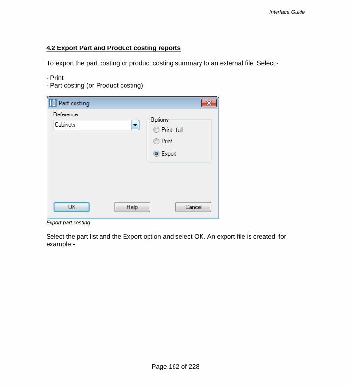
Interface Guide
Page 162 of 228
4.2 Export Part and Product costing reports To export the part costing or product costing summary to an external file. Select:- - Print - Part costing (or Product costing)
Export part costing Select the part list and the Export option and select OK. An export file is created, for example:-

Interface Guide
Page 163 of 228
Edging and laminates.EX2
Export file - part costing Product costing exports a file with the extension: EX1 Part costing exports a file with the extension EX2 The export files are placed in the directory set by the System parameter: Path for Export data The export file can contain three types of data: 1 - header line (no comma separated fields) 3 - data line with comma separated fields 4 - total line with comma separated fields
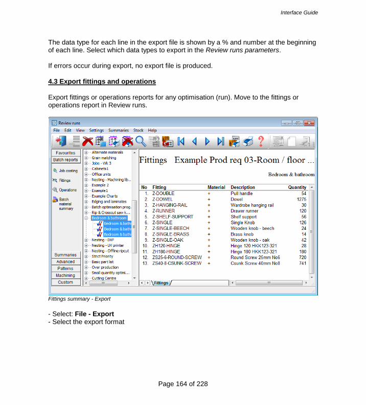
Interface Guide
Page 164 of 228
The data type for each line in the export file is shown by a % and number at the beginning of each line. Select which data types to export in the Review runs parameters. If errors occur during export, no export file is produced. 4.3 Export fittings and operations Export fittings or operations reports for any optimisation (run). Move to the fittings or operations report in Review runs.
Fittings summary - Export - Select: File - Export - Select the export format

Interface Guide
Page 165 of 228
The Excel formats (XLS and XLSX) export to an Excel file.
Export fittings - Excel ASCII export - the data is exported to a file with the same name as the fitting or operations list with the report letter appended and extension exd (e.g. BSR81-CDU.exd for fittings). The export files are placed in the directory set by the System parameter: Path for Export data 4.4 Export cutting lists Export cutting lists and boards lists as part of the optimisation or recalculation process. To do this set the System parameter: Create data for to create to one of the following:- Exported cutting list - parts only Exported cutting list - parts and boards

Interface Guide
Page 166 of 228
Also set System parameter: Export cutting list format
System parameters - Export cutting list format

Interface Guide
Page 167 of 228
PNX/BDX (2000 parts) PNX/BDX (250 parts) These options produce cutting lists and/or board lists in an ASCII/Unicode format. This is useful if the lists are going to be used by other systems. The export occurs automatically when the part list is optimised. The ASCII/Unicode format is the PNX and/or BDX format. Kitchen layout DEFAULT DEFAULT BASE-BACK,HARDBOARD-4MM,976.000000,735.000000,1,0,0,0,0,0,0,0,,,,,,,,976.0 x 735.0,00000449* BASE-BACK,HARDBOARD-4MM,476.000000,735.000000,1,0,0,0,0,0,0,0,,,,,,,,476.0 x 735.0,00000450* BASE-BACK,HARDBOARD-4MM,876.000000,735.000000,1,0,0,0,0,0,0,0,,,,,,,,876.0 x 735.0,00000451* BASE-BACK,HARDBOARD-4MM,976.000000,735.000000,1,0,0,0,0,0,0,0,,,,,,,,976.0 x 735.0,00000452* BASE-BACK,HARDBOARD-4MM,976.000000,735.000000,1,0,0,0,0,0,0,0,,,,,,,,976.0 x 735.0,00000453* BASE-BACK,HARDBOARD-4MM,476.000000,735.000000,1,0,0,0,0,0,0,0,,,,,,,,476.0 x 735.0,00000454* BASE-BACK,HARDBOARD-4MM,976.000000,735.000000,1,0,0,0,0,0,0,0,,,,,,,,976.0 x 735.0,00000455* BASE-BACK,HARDBOARD-4MM,976.000000,735.000000,1,0,0,0,0,0,0,0,,,,,,,,976.0 x 735.0,00000456* BASE-BACK,HARDBOARD-4MM,476.000000,735.000000,1,0,0,0,0,0,0,0,,,,,,,,476.0 x 735.0,00000457* BASE-BACK,HARDBOARD-4MM,476.000000,735.000000,1,0,0,0,0,0,0,0,,,,,,,,476.0 x 735.0,00000458* BASE-BOTTOM,MED-DEN-FIBRE-18MM,564.000000,581.000000,3,0,0,0,0,0,0,0,OAK-TAPE-22MM,,,,,,,564.0 x 582.0,00000459* BASE-BOTTOM,MED-DEN-FIBRE-18MM,464.000000,581.000000,1,0,0,0,0,0,0,0,OAK-TAPE-22MM,,,,,,,464.0 x 582.0,00000460* BASE-BOTTOM,MED-DEN-FIBRE-18MM,464.000000,581.000000,1,0,0,0,0,0,0,0,OAK-TAPE-22MM,,,,,,,464.0 x 582.0,00000461* BASE-BOTTOM,MED-DEN-FIBRE-18MM,464.000000,581.000000,1,0,0,0,0,0,0,0,OAK-TAPE-22MM,,,,,,,464.0 x 582.0,00000462* BASE-BOTTOM,MED-DEN-FIBRE-18MM,464.000000,581.000000,1,0,0,0,0,0,0,0,OAK-TAPE-22MM,,,,,,,464.0 x 582.0,00000463* BASE-CABINET-BOTTOM,MED-DEN-FIBRE-18MM,864.000000,581.000000,1,0,0,0,0,0,0,0,OAK-TAPE-22MM,,,,,,,864.0 x 582.0,00000464* BASE-CABINET-DIVIDER,MED-DEN-FIBRE-18MM,559.000000,533.250000,1,0,0,0,0,0,0,0,,,OAK-TAPE-22MM,,,,,560.0 x 533.3,00000465* BASE-CABINET-DOOR,MFC18-OAK,398.000000,554.750000,1,0,0,2,0,0,0,0,OAK-TAPE-22MM,OAK-TAPE-22MM,OAK-TAPE-22MM,OAK-TAPE-22MM,,,,400.0 x 556.8,00000466* ..... HARDBOARD-4MM/01,795,HARDBOARD-4MM,2000.000000,1000.000000,4.000000,0.890000,9

Interface Guide
Page 168 of 228
HARDBOARD-4MM/02,131,HARDBOARD-4MM,2440.000000,1220.000000,4.000000,0.750000,0 MED-DEN-FIBRE-18MM/01,1090,MED-DEN-FIBRE-18MM,3660.000000,1550.000000,18.000000,4.500000,0 MED-DEN-FIBRE-18MM/02,767,MED-DEN-FIBRE-18MM,2440.000000,1220.000000,18.000000,4.350000,0 MFC18-OAK/01,430,MFC18-OAK,3050.000000,1220.000000,18.000000,3.300000,0 MFC18-OAK/02,111,MFC18-OAK,2440.000000,1220.000000,18.000000,2.970000,0 WHAC12/01,436,WHITE-ACRYLIC-12MM,2440.000000,1220.000000,12.000000,1.320000,4 The other options for 'Export cutting list format' are for special situations where part list are exported after processing to other systems. 4.5 Export - Pattern Exchange Format The Pattern exchange format contains all the part sizes, board sizes, parameter settings, cutting instructions and drawing information for a run and most of the summary data. Use this to export optimisations (runs) for use by other systems such as a spread sheet, database, or report generator. This is the program's proprietary format for patterns (results). It is used by several manufacturers where they want pick up information from the optimisation results (cutting patterns). It is a public format and fully described in Section 3 (above). All the pattern data and structure is contained in the file in ASCII/Unicode or MDB database format - so it is very useful where custom changes are needed for controlling specific machines or external systems. For example, to update stock control systems, use a special post processor to transfer to a saw.

Interface Guide
Page 169 of 228
In this case the ‘export’ occurs as part of the saw or machine transfer process. This is set up as a tranfer mode (transfer option) at the Saw Transfer parameter screen.
Export - Pattern exchange format Quite often both the standard .saw file and the .ptx file are used by a manufacturer. In this case both files can be exported in a single command by grouping This option is also available for transfer to Machining centres. At the main screen select the Run to transfer and then the transfer method.

Interface Guide
Page 170 of 228
The file is exported.

Interface Guide
Page 171 of 228
In this case the file is located in the ‘Path for Saw data’.

Interface Guide
Page 172 of 228
4.6 Export - Board library data It is sometimes useful to export the entire contents of the board library to an external file, for example, to update a supporting system. At the Board library screen:-
Board library - Export - Select: File - Export

Interface Guide
Page 173 of 228
The program prompts for a path and file name.
Board library - Export dialog BDX format This is a special format for Boards; one line per board including material information. It can be useful for external processing and data can also be re-imported to the Board library via the Import options with this format. BDX is the current format. The data can either be exported to a Fixed file (BRDLIB.BDX) in the directory set by the System parameter: Path for export data or to a selected file path and name. (See section 2.3 above for details of the BDX format). 4.7 Export - Part library data It is sometimes useful to export all the Part library data, for example, for updating external systems. At the Part library screen:- Select: File - Export The library data is exported to a comma separated value file with a fixed name. PARTLIB.CSV The file is located in the folder set by the System parameter: Path for Export data If the parameter setting is blank or there is some other problem with the file an error is reported.

Interface Guide
Page 174 of 228
File format Each line contains a record from the part library. The order of the fields is as follows:- Code Material Description Length Width Grain Edge Cost Drawing code Information boxes Notes - Grain values in the file are:- 0=No 1=Yes 2=X 3=Variable - Quick/Short edge codes are exported as one 4 digit field (e.g. 0000) - Grain and edge fields are blank for fitting and operations and the cost field is blank for parts. 4.8 Export - Product data At the product library screen there are several options to export data. - Export product - Export library - Export product list Export product The export product option is used to export a single product from the library, which includes the part details and any variables, formulae or lookups used.

Interface Guide
Page 175 of 228
When the option is selected a .PLE file is created in the path for export data based on the name of the currently selected product. e.g. If the current product is BASE-OVEN-HSE the file is:BASE-OVEN-HSE.PLE This file can then be subsequently imported into another user profile or into the same user profile if the product is modified and needs to be reset. The PLE format is an internal format. Export library The export is to an 'Access' MDB format database There are 9 tables named as follows: Products - Contains product details (not the part grid at the bottom of product library) Subassemblies - Contains the subassembly details (not the part grid information) Parts - Contains the part details from the part library ProductParts - Contains which parts appear in which products (part grid information) ProductSubs - Contains which subassemblies appear in which products (part grid inf.) SubParts - Contains which parts appear in which subassemblies (part grid inf.)

Interface Guide
Page 176 of 228
Variables - Contains the variable table details Formulae - Contains the formulae table details Lookups - Contains the lookup table details
The fields for each table are:- Products Code, Description, Width, Default width, Height, Default height, Depth, Default depth, VerticalPos, DefaultVerticalPos, Drawing, Planview, Elevationview, Price, AnswerTable, Memo1 to Memo10

Interface Guide
Page 177 of 228
Subassemblies Code, Description, Width, Default width, Height, Default height, Depth, Default depth, Drawing Parts Code, Material, Description, Length, DefaultLength, Width, DefaultWidth, Grain, Edging, DrawingType, Drawing, Cost, Infobox1 to Infobox99 Productparts Product, Part, Qty/time, Material, Length, Width ProductSubs Product, Subassembly, Qty/time, Material, Length, Width SubParts Subassembly, Part, Qty/time, Material, Length, Width Variables Name, Format, Directory, Type, InformationBox, Description, Default, Range Formulae Name, Description, Formula Lookups Name, Description, Value

Interface Guide
Page 178 of 228
Export product list This creates a file: MPRODLIST.csv (for millimeters) or IPRODLIST.CSV (for inches). The file is located in the 'Path for Export'.
A line is produced for each product in the library with the fields in the following order: Code, Description, Height, Width, Depth, Memo1, Memo2, Memo3, Memo4, Memo5,Price,Drawing name,Variable1,default answer1,Variable2,default answer 2... The drawing name field contains the sketch name, not the plan or elevation names. This field can be blank (empty) but there may still be a product drawing which matches the product name.

Interface Guide
Page 179 of 228
The product variables and default answers repeat as many times as required. Default answers are taken from the variables table. If there is no default answer, the answer field is blank (e.g. @variable1@,,@variable2@...). Global variables will appear in the list against each product. If a product contains parts / machine drawings which have variables, these variables also appear in the list. This also applies to variables which occur in formulae or look-ups which occur in the product, parts or machine drawings. Sub-assemblies and accessories are not exported. The list of parts that comprise a product are also not exported. 4.9 Export variables deployment list This option lists where variables names are used across the product library, part library, machining library and drawing library. At the main screen:- - Select: File - Export variables deployment list - Select the file format for the file. CSV XLS XLSX If the file already exists the program prompts to overwrite the file. The file is located in the 'Path for Export data' the file name is based on the date. e.g. VARDEPLIST 2015-11-19 1420.xls The file line of the file contains the following 5 text headings: Product, Part, Machining, Drawing, Variable The following lines list all the places where a variable is used, for example:- 1. BASE-CABINET,,, BCAB1 This means the variable BCAB1 is used in the product BASE-CABINET (and not in any part, machining or drawing) 2. BASE-CABINET,BASEPART1,,BCAB2

Interface Guide
Page 180 of 228
This means variable BCAB2 is used in product BASE-CABINET and part BASEPART1, but not in a machining item or drawing. 3. BASE-CABINET,,MCH1,,BCAB3 This means variable BCAB3 is used in product BASE-CABINET and machining drawing MCH1, but not in a part or a drawing 4. ,TPART1,,,VAR2 This means the variable VAR2 is not in any product, machining item or drawing but is used in part TPART1.

Interface Guide
Page 181 of 228
The first items in the file are based on product variables and below (parts belonging to the product and associated drawings), then variables used for any remaining unused parts and below, next any remaining machining drawing and finally any remaining drawing library items.

Interface Guide
Page 182 of 228
5. Stand alone operation It is sometimes useful to run portions of the Optimising software as ‘stand alone’ programs. For example, to automate the process of importing and optimising or to automate a stock update or to interface with other systems. Optimising program setup - stand alone operation is a way of running the program with no operator input BUT a lot of information still comes from the Optimising program which has to be set up in the usual way. That is, parameters set and co-ordinated, boards and materials available in the Board library, drawings available in the Machining library etc. Make sure that the operations work using the FULL program before attempting to create the stand alone operation Instructions - these are specific for each stand alone item so follow the examples carefully . Running the Import program - example A typical task is to import parts from a PTX file as a stand alone operation. Run the program IMPORT.EXE from a user profile. This can be from a batch file or from a shortcut or by using the Windows option Start - Run. For example, using a Windows batch file the commands are:- ..\import job32.ptx /format:8 User profile - It is important to run the program from a user profile to locate the system parameter settings for paths and other values required. Errors - when a program runs in 'silent' mode this means that the usual method of reporting errors is not available because the on-screen list of errors cannot be displayed. Any errors are stored in the file IMPORT.ERR 5.1 Import parts / boards / patterns - stand alone Using program Import services with other systems via the command line or a batch file Use the program: IMPORT IMPORT [filename] [/FORMAT:nn] [/OVERWRITE] [/RENAME] [/DELETE] [/NOWRTBRD] [/UDF] [/SEP] [/UTF-8|/UFT-16LE]

Interface Guide
Page 183 of 228
filename - path and name of the file to import The stand alone import mode of the import program allow users to specify Unicode format files by using /UTF-8 or /UTF-16LE on the command line e.g. IMPORT c:\importdir\files\parts.pnx /FORMAT:3 /UTF-8 Format Set the import type /FORMAT:nn The import types for parts and boards are as follows:- 0 - Part list order – ASCII/Unicode CSV (PNX) 1 - Cabinet Vision format 2 - Product Planner format 3 - Code and quantity – ASCII/Unicode CSV (PNX) 4 - Batch - part list order (BTX & PNX) 5 - Batch - Code and quantity (BTX & PNX) 6 - User defined order – ASCII/Unicode CSV (PNX) 7 - Batch - user defined order (BTX) 8 - Parts & boards – ASCII/Unicode CSV (PTX) 9 - Parts & boards - Access (MDB) 10 - Cut Planner format 11 - MSS/Keytrix format 12 - Giben Optisave AC & AD files 13 - Pattern exchange – ASCII/Unicode CSV (PTX) 14 - Pattern exchange - Access (MDB) 15 - Giben Optisave - AC file only 16 - BDX format 17 - Board list - User defined order ASCII/Unicode CSV 20 - XLS parts 21 - XLSX parts 30 - XLS boards 31 - XLSX boards

Interface Guide
Page 184 of 228
For example: IMPORT c:\importdir\files\parts.pnx /FORMAT:3 IMPORT jobs.ptx /FORMAT:13 When using /FORMAT the program runs in silent mode (same as /AUTO) and any errors are sent to a .ERR file. Delete Delete original files /DELETE Overwrite Overwrite or replace existing files /OVERWRITE Only applies to types 12 and 15. /OVERWRITE command means overwrite all existing files. Rename /RENAME Batch name is allocated a unique number from the same series as quotes/requirements (sonumber.ctl). The part list names are created by using the first five digits of the batch number and the first 3 characters of the job list name. e.g. BRJOB.PTX contains jobs WRK and NST IMPORT BRJOB.PTX /RENAME /PARTS /AUTO Batch file created:- 00004.BTC 00004WRK.PRL 00004NST.PRL

Interface Guide
Page 185 of 228
It is important to ensure that, when using this option, the first three characters of each job name are unique within that PTX file. You cannot have, for example, 'BSR10' and 'BSR15' as job names unless these are placed in separate PTX files. Silent Run without prompts etc. /AUTO Alternative commands /PARTS /BOARDS /PATTERNS These commands can be used as an alternative to the FORMAT command. When using these commands the relevant import parameter is used for the import format and the System parameter: Path for import data must be set Errors - When you work with a command like '/AUTO' so that a program runs in 'silent' mode this means that the usual method of reporting errors is not available because the on-screen list of errors cannot be displayed. Any errors are stored in the file IMPORT.ERR Delete product requirement import files - these can be deleted after import. This is done at the Import - Requirements dialog box. Check the box 'Delete files after import'. Import files can also be deleted when running the program in the stand-alone mode. Use argument /DELETE to give the command line: PRODIMP.EXE ["file name.ext"] [/QUOTE] [/AUTO] [/DELETE] Omit /DELETE if deletion is not required Quotation marks are not needed if the file name does not contain spaces Use /AUTO for stand-alone operation. /QUOTE – necessary for importing quotes, otherwise this program will start in import requirement mode User defined /UDF

Interface Guide
Page 186 of 228
Where there is an import parameter for user defined parts or boards the parameter file can be specified on the command line with the UDF option. IMPORT.EXE TESTFILE.IMP /FORMAT:6 /UDF:Myparts Where the file name includes spaces the name must be enclosed in quotes. IMPORT.EXE TESTFILE.IMP /FORMAT:6 /UDF:"My parts" The /UDF argument only applies if /FORMAT:6 or /FORMAT:7 are also set. Separator /SEP:<separator> Specify the separator for the file. e.g. /SEP:58 /SEP:":" The separator is either the decimal Ascii number or the character enclosed in quotes The separator can be any ASCII code between 32 and 127 except the following (0 to 9, A to Z or a to z). If the separator is not valid an error is reported. Existing board list /NOWRTBRD Only applies to part list import Stops the program deleting the existing board list - this allows the program to re-use a board list. 5.2 Export reports - stand alone Using program Output services via the command line or a batch file to print or export data Use program: OUTPUT

Interface Guide
Page 187 of 228
This allows printing or export of runs / summaries. There are several different options available:- /PRINT - print /EXPORT - export to ASCII files /EXPORT /MDB - export to Access database Printing /PRINT=<printername> - specify the printer /REPORTS=<reportletters> - set the reports to print /RUN=<runumber> - set the run name / number Reports are specified with a report letter (see below). For example:- OUTPUT /PRINT /REPORTS=BCE OUTPUT /PRINT=\\SERVER\LASERJET4 /RUN=00027 /REPORTS=BCE Export to ASCII file(s) /EXPORT - export to ASCII files /REPORTS=<reportletters> - set the reports to print /RUN=<runumber> - set the run name / number Reports are specified with a report letter (see below). For example:- OUTPUT /EXPORT /REPORTS=BCE OUTPUT /EXPORT /RUN=00027 /REPORTS=BCE Export to MDB file /EXPORT /MDB - export to Access database /REPORTS=<reportletters> - set the reports to print /RUN=<runumber> - set the run name / number Reports are specified with a report letter (see below). For example:- OUTPUT /EXPORT /MDB /REPORTS=BCE OUTPUT /EXPORT /MDB /RUN=00027 /REPORTS=BCE
Interface Guide
Page 188 of 228
Export to XLS/XLSX /EXPORT /XLS - export to Excel /EXPORT /XLXS - export to Excel Errors Any errors are sent to a .ERR file. Report letters A Batch Summary B Management Summary C Pattern Summary D Part Summary E Board Summary F Offcut summary G Distribution summary H Input summary I Destacking summary J Pattern drawing N Edging summary O Material summary P Machine times Q Saw loading summary R Station summary T Job costing U Fittings V Operations Y Sundry parts 1 Nested Preview 2 Nested Drawings 3 Saw simulation 4 Nested pieces 5 Nested parts 6 Batch material summary Override export path The location of exported files can be temporarily overridden when exporting review runs data by using the OUTPUT program in stand alone mode. The command line argument is /EXPORTPATH followed by the path for export data. This path can also be a UNC path, for example:-

Interface Guide
Page 189 of 228
..\OUTPUT.EXE /EXPORT /REPORTS=J /EXPORTPATH=O:\EXPORT\
..\OUTPUT.EXE /EXPORT /REPORTS=J /EXPORTPATH=\\SERVER\EXPORT\ If a path contains spaces then the path must be surrounded with quotes, for example: ..\OUTPUT.EXE /EXPORT /REPORTS=BCD /EXPORTPATH="O:\SPACED PATH\" If the path specified is not valid the export does not take place Send to PDF Send to PDF Create a printout as a PDF file. Use the /PDF argument:- ..\OUTPUT.EXE /PDF /REPORTS:BC '/PRINT' is not needed if '/PDF' is used. To use PDF there must be at least one printer driver installed on the system. Running the Output program - example A typical task is to export some of the reports to an ASCII file Run the program OUTPUT.EXE from a user profile. This can be from a batch file or from a shortcut or by using the Windows option Start - Run. For example, using a Windows batch file the commands are:- ..\output /export /reports=CD In this example the reports exported are the Pattern Summary (C) and the Part summary (D). The current run is used unless the /RUN option specifies a different run. User profile - It is important to run the program from a user profile to locate the system parameter settings for paths and other values required. Errors - when a program runs in 'silent' mode this means that the usual method of reporting errors is not available because the on-screen list of errors cannot be displayed. Any errors are stored in the file OUTPUT.ERR Note - If these commands are to be run from the Auxiliary menu then the equals sign should be replaced with a colon.

Interface Guide
Page 190 of 228
..\OUTPUT.EXE /PDF /REPORTS:BC 5.3 Export Library data - stand alone Board library Use the program: BOARD BOARD [ /BDX] This creates the file brdlib.bdx in the path set by the system parameter: Path for Export data ..\BOARD /BDX The program should be run from a 'User profile' either by running the program from that profile (with the Windows Run command or a Batch file) or by setting the 'Start in' option on a shortcut. An example of a batch file is the following. CD \USER1 C:\USER1\BOARD.EXE /BDX Export part and product library data Stand alone options to export the full libraries Part library Use the /EXPORT command line argument. This creates a file: PRTLIB.csv c:\v10\PARTS.EXE /EXPORT The file is located in the 'Path for Export'. Product library Use the /EXPORT command line argument. This creates a file: MPRODLIST.csv (for millimeters) or IPRODLIST.CSV (for inches). c:\V10\PRODLIB.EXE /EXPORT

Interface Guide
Page 191 of 228
The file is located in the 'Path for Export'. 5.4 Batch operations - stand alone Many operations such as optimising work as a batch operation - even if, for example, only one cutting list is optimised. For stand alone operation you often need to run the batch process - the following are the instructions to achieve this. The program for batch operations is BATCH.EXE. The command syntax is as follows. BATCH [filename] [/AUTO] [/OPTIMISE] filename - the name of the file to apply batch operations to. Batch file (filename.BTC), part list (filename.PRL), or cutting list (filename.CTT). Square brackets [ ] indicate that the command is optional. If no filename is specified the current batch is used. Note - option '/OPTIMISE' can also be spelt as '/OPTIMIZE' For example:- BATCH DEMO1.PRL /AUTO /OPTIMISE (Optimises the part list DEMO1). /AUTO - silent operation - no dialogs or error messages are displayed. /OPTIMISE - optimisation of the named file The /AUTO argument is needed with /OPTIMISE. For example: A batch file to import parts from a pattern exchange file (ptx) , optimise the batch and transfer information to the saw and machining centre. ..\IMPORT %1 /AUTO /PARTS

Interface Guide
Page 192 of 228
-..\BATCH /AUTO /OPTIMISE ..\SAWLINK /AUTO /1 ..\MCHLINK Note - during optimisation any cutting lists or board lists that do not exist are automatically created. If no name is specified for a batch optimisation (e.g. BATCH.EXE /AUTO /OPTIMISE), the current batch is used and any cutting lists that do not exist for the batch are created. If a filename is specified for a batch optimisation but there is no file extension the program looks for <filename>.BTC first, <filename>.CTT next and <filename.PRL last. If none of these exists, an error message is placed in the error file (!.ERR) The system of automatically dividing cutting lists that apply when optimising from the part list program also applies for BATCH.EXE standalone optimising. This is based on the 'Optimise options' and 'Category for part list divide' system parameters. Import user defined parts - import parameter file for user defined parts can be specified on the command line. This is handled with the /UDF command line argument. IMPORT.EXE TESTFILE.IMP /FORMAT:6 /UDF:02 This uses the user defined format 02 which has .IMP as its file extension. Errors are output if the user defined format file does not exist. The /UDF argument only applies if /FORMAT:6 or /FORMAT:7 is used, any other format will generate an error message. Import user defined product requirements - The /UDF command line argument can also be used to specify the product requirement import parameter file when import products. Remaining parts - in /AUTO mode there is no dialog to save any remaining or invalid parts (if they exist). Invalid parts are reported in the error file. - For stand alone operation - the parameter 'Prompt before modifying existing list' parameter is ignored and all board lists are updated if possible.

Interface Guide
Page 193 of 228
Example using batch operations A Windows batch file to import parts from a pattern exchange file (ptx) , optimise the batch and transfer information to the saw and machining centre. ..\IMPORT %1 /FORMAT:8 ..\BATCH /AUTO /OPTIMISE ..\SAWLINK /AUTO /1 Note - during optimisation any cutting lists or board lists that do not exist are automatically created. %1 is the usual Windows batch command line variable which is a place holder for the file name. User profile - It is important to run the programs from a user profile to locate the system parameter settings for paths and other values required Errors - when a program runs in 'silent' mode this means that the usual method of reporting errors is not available because the on-screen list of errors cannot be displayed. Any errors are stored in the file !.ERR Ignore errors /IGNOREBRDERR The optimisation may report errors but continues. BATCH DEMO1.PRL /AUTO /OPTIMISE /IGNOREBRDERROR This can be useful where the list contains boards of zero dimension ( 0 x 0 ) which remain in the board list, for example, when using combination materials. 5.5 Stock update and stock issue - stand alone Using program Stock control services via the command line / batch file Use program: STOCK There are several different options available:- /IMPORTSTOCK - import stock

Interface Guide
Page 194 of 228
/OVERWRITESTOCK - overwrite stock /ISSUESTOCK - issue stock /ALLOCSTOCK - allocate stock /RESET - month/year end report /UDF - user defined import /UTF-8 - unicode format 8 import file /UTF-16LE - unicode format 16LE import file These are separate options for the Stock program. Import stock STOCK <filename> /IMPORTSTOCK [/FORMAT:n] [/UPDATEEXISTING] [/ADDNEWSTOCK] [/SEP:<separator>] filename - file with stock information. This must include the correct file extension. STOCK MyBoards.bdx /IMPORTSTOCK The basic operation is to add incoming values to existing ones. Import file MFC15-03 2440 x 1220 98 MFC15-04 3660 x 1830 15 MFC15-05 2010 x 1680 61 Board library BEFORE AFTER MFC15-03 2440 x 1220 320 MFC15-03 2440 x 1220 418 MFC15-04 3660 x 1830 26 MFC15-04 3660 x 1830 41 The Unicode format of files can be configured for stock import into the board library by using either /UTF-8 or /UTF-16LE on the command line. e.g. STOCK MyBoards.bdx /IMPORTSTOCK /UTF-8 The format can be set via the System parameters in the user profile or via the /FORMAT switch. The format must match the file name extension. STOCK MyBoards.bdx /IMPORTSTOCK /FORMAT:1 The numbers for the /FORMAT switch are:- 0 - BRD format 1 - BDX format

Interface Guide
Page 195 of 228
2 - Bargstedt stock file BESTAND.STK 3 - External SQL database 4 - User defined order – ASCII/Unicode CSV 5 - User defined order - Excel XLS 6 - User defined order - Excel XLSX To also add any new stock (Board and offcuts) use the /ADDNEWSTOCK switch. STOCK MyBoards.bdx /IMPORTSTOCK /FORMAT:1 /ADDNEWSTOCK Import file MFC15-03 2440 x 1220 98 MFC15-04 3660 x 1830 15 MFC15-05 2010 x 1680 61 Board library BEFORE AFTER MFC15-03 2440 x 1220 320 MFC15-03 2440 x 1220 418 MFC15-04 3660 x 1830 26 MFC15-04 3660 x 1830 41 MFC15-05 2010 x 1680 61 To increase / decrease any existing stock values with those in the import file use the /UPDATEEXISTING switch STOCK MyBoards.bdx /IMPORTSTOCK /FORMAT:1 /ADDNEWSTOCK /UPDATEEXISTING Import file MFC15-03 2440 x 1220 98 MFC15-04 3660 x 1830 15 MFC15-05 2010 x 1680 61 Board library BEFORE AFTER MFC15-03 2440 x 1220 320 MFC15-03 2440 x 1220 98 MFC15-04 3660 x 1830 26 MFC15-04 3660 x 1830 15 MFC15-05 2010 x 1680 61 For the BDX format only - a separator can be specified; this is useful where the BDX fields are separated by a character other than a comma, for example a colon. STOCK MyBoards.bdx /IMPORTSTOCK /FORMAT:1 /SEP:":" The separator can be specified as a character or a number e.g. /SEP:58 or /SEP:":" Overwrite stock STOCK <filename> /OVERWRITESTOCK [/FORMAT:n] [/OVERWRITEEXISTING] [/SEP:<separator/]

Interface Guide
Page 196 of 228
filename - file with stock information. This must include the correct file extension. STOCK MyBoards.bdx /OVERWRITESTOCK The basic operation is to add new stock (Boards and offcuts) to the library. Import file MFC15-03 2440 x 1220 98 MFC15-04 3660 x 1830 15 MFC15-05 2010 x 1680 61 Board library BEFORE AFTER MFC15-03 2440 x 1220 320 MFC15-03 2440 x 1220 320 MFC15-04 3660 x 1830 26 MFC15-04 3660 x 1830 26 MFC15-05 2010 x 1680 61 The format can be set via the System parameters in the user profile or via the /FORMAT switch. The format must match the file name extension STOCK MyBoards.bdx /OVERWRITESTOCK /FORMAT:1 The numbers for the /FORMAT switch are:- 0 - BRD format, 1 - BDX format, 2 - Bargstedt stock file BESTAND.STK. To overwrite the quantities of existing board codes use the /OVERWRITEEXISTING switch. STOCK MyBoards.bdx /OVERWRITESTOCK /FORMAT:1 /OVERWRITEEXISTING Import file MFC15-03 2440 x 1220 98 MFC15-04 3660 x 1830 15 MFC15-05 2010 x 1680 61 Board library BEFORE AFTER MFC15-03 2440 x 1220 320 MFC15-03 2440 x 1220 98 MFC15-04 3660 x 1830 26 MFC15-04 3660 x 1830 15 MFC15-05 2010 x 1680 61 For the BDX format only - a separator can be specified; this is useful where the BDX fields are separated by a character other than a comma, for example a colon. STOCK MyBoards.bdx /OVERWRITESTOCK /FORMAT:1 /SEP:":" The separator can be specified as a character or a number e.g. /SEP:58 or /SEP:":"
Interface Guide
Page 197 of 228
Can also include the /BOARDOPTIONS and /OFFCUTOPTIONS commands to control the overwrite process. e.g. STOCK.EXE /OVERWRITESTOCK /BOARDOPTIONS:1 /OFFCUTOPTIONS:0 The options are:- 0 = do nothing 1 = clear quantities 2 = remove items Import or Overwrite stock from external SQL database This follows the rules in the above sections. An example is:- STOCK /IMPORTSTOCK /FORMAT:3 /UPDATEEXISTING /ADDNEWSTOCK STOCK /OVERWRITESTOCK /FORMAT:3 The relevant system parameters must be set to make the link to the external database. Issue stock STOCK /ISSUESTOCK This issues stock for the current run. This can also include the command: /OPT to control the stock update, e.g. STOCK /ISSUESTOCK /OPT:23 Options are:- 1 - Adjust boards 2 - Adjust offcuts 3 - Add offcuts 4 - Adjust edging 5 - Adjust fittings 6 - Adjust monthly summary Allocate stock STOCK /ALLOCSTOCK

Interface Guide
Page 198 of 228
Allocation records are assigned the current date in the 'cut date' field. This allocates stock for the current run. Reset Transactions STOCK /RESET Produces the End of Month / Year report. Stock transactions (audit trail) are automatically exported to an external file. The external file is located in the: Path for Stock libraries (if set) other it is located in the Path for library data. For example:- Transactions 2015-09-25 1305.csv Import stock from file in user defined format /UDF Example: /UDF:"board import" The default extension is ubx. If the file name is not set the program uses the file specified in system parameters. Other options are: [/UPDATEEXISTING] [/ADDNEWSTOCK] [/SEP:<separator>] The /SEP option takes precedence over the separator specified in the board import parameters. Notes - separator can be any ASCII code between 32 and 127 except the following (0 to 9, A to Z or a to z). - for /FORMAT the program runs in silent mode and any errors are sent to a .ERR file. Stand alone Minimum free stock report Use program: STOCK STOCK /MINFREESTOCK

Interface Guide
Page 199 of 228
The output defaults to all materials rather than prompting for a range. The minimum free stock report appears on screen and may be printed in the usual way. 5.6 Import product requirements - stand alone Use program: PRODIMP PRODIMP [filename] [/AUTO] [/DELETE] [/UDF:<parameter filename>] /[SEP:<separator] [/CALCPARTS] [/FORMAT:nn] [/IGNORENULL] filename - file with requirements information /AUTO - silent running /DELETE - delete import file User defined Import stock from file in user defined format /UDF Example: /UDF:"board import" The default extension is ubx. If the file name is not set the program uses the file specified in system parameters. Other options are: [/UPDATEEXISTING] [/ADDNEWSTOCK] [/SEP:<separator>] The /SEP option takes precedence over the separator specified in the board import parameters. Separator /SEP:<separator> Specify the separator for the file. /SEP:58

Interface Guide
Page 200 of 228
/SEP:":" The separator is either the decimal ASCII number or the character enclosed in quotes. The separator can be any ASCII code between 32 and 127 except the following (0 to 9, A to Z or a to z). If the separator is not valid an error is reported. Calculation of parts /CALCPARTS Creates the part list and cutting list automatically File format /FORMAT:nn 0 - CSV 1 - XLS 2 - XLSX e.g. /FORMAT:1 Ignore Null variable answers /IGNORENULL If this is used then any NULL values in the file will not be used to blank out variable answers during the import process. Errors Any errors created during import and generation of the product requirement file, part list and cutting list files are placed in the PRODIMP.ERR file. Note /CALCPARTS can only be used in standalone mode and therefore needs to be run with the /AUTO command.

Interface Guide
Page 201 of 228
5.7 Saw transfer - stand alone Use the program: SAWLINK SAWLINK [/Switches] Use the various switch options to specify the details of the transfer, for example:- ..\sawlink /AUTO ..\sawlink /AUTO /SAWPATH="c:\Saw transfer" /TRANSMODE=6 /CADMATIC=CAD4 Switches Switch Options Example Default /SAWPATH=name Full path name /SAWPATH="c:\saw transfer" current directory /TRANSMODE=number Saw transfer mode number (2 -
14) /TRANSMODE=3 6 (Cadmatic III)
/WARNING=number Retransfer warning level (1 or 2) /WARNING=1 0 (not set) /ONLINEPATH=name Full path for online data /ONLINE=c:\MySawData blank (no path set) /LOGIN=number:name:password
Authentication required User name Password
/LOGIN=1:userjones:dfxgy 0 (login not used)
/SAFE=number:value:value
Safe transfer enabled (0-1) Timeout 1 Timeout 2
/SAFE=1:3:5 0 (not used)
/SPARE=text blank /PTXOPTIONS=command P - prompt before overwrite
R - one file per run /PTXOPTIONS=P /PTXOPTIONS=PR
blank (not set)
/CPOUT=number Cpout naming method (0-1) /CPOUT=1 0 /ILENIA=number Ilenia controller Use Ilenia controller (0-1) /ILENIA=1 0 /CADMATIC=code Type of Cadmatic
CADR - Cadmatic III recursive CAD4 - Cadmatic 4
/CADMATIC=CAD4 blank (Cadmatic III)
/IMAGE=format code,color code Colour codes (BMP,BMP24,BMP, BMP16,BMP256,WMF,EMF) Use colour (0-1)
/IMAGE=BMP256,1 blank (not set)
/ALPHA=number
Allow alphanumeric runs for Cadmatic 1/II (0-1)
/ALPHA=1 0 (not set)
/COMMSPORT=port code
Communication port for saw /COMMSPORT=COM1 blank (not set)
/GROUP=number Transfer to group (group number)
/GROUP=1 blank (not set)
/RUN-name Run number to use /RUN=10023 current batch /AUTO
Stand alone (silent) operation /AUTO
/DXFOPTIONS Specify output format for DXF files
/DXFOPTIONS=1:0:1:1 1=include 0=do not include
/DELETE
Delete runs after transfer /DELETE
Interface Guide
Page 202 of 228
/number
Saw number (line number of saw transfer parameters (0-6)
/1
Refer to the Saw transfer parameters for full details of each option Notes - For file names and commands with spaces use quotation marks to enclose the text - Specifying a run to transfer. The run can be either a name or a run number:- /RUN=00001 /RUN="Week 1" If any run files are missing an error is reported - The format of the commands reflects the usage in the previous Options command - /GROUP - this refers to the number of the group in the saw transfer parameter list. The first group in the list is group 1 and the next group 2 etc. Previous commands - /AUTO, /DELETE, and /number are the previous commands - these can still be used in the same way. But do NOT use with any of the other commands; in this case /number means that any other command options are ignored. This also applies to the new /GROUP command. /AUTO automatic and silent transfer of files 'Automatic and silent' - means that the transfer program does not use screen displays or report prompts and errors on screen. Transfers the current batch of runs. /DELETE - remove original files Run files are deleted from the directory set by the System parameter: Path for data, when the whole batch is successfully transferred to the saw. Only files associated with the current batch are deleted (<run>.*). /n saw number The 'n' stands for the number of the item in the saw transfer parameter list.

Interface Guide
Page 203 of 228
e.g. ..\SAWLINK /AUTO /1 /delete Previously for saw transfer the /DELETE option also deleted any parameter files associated with run. This is no longer done. The files deleted are:- Run name.* - any file matching the run name in the Path for data Cutting list (.ctt) - from 'Path for part lists' if set or 'Path for data' otherwise Part list (.prl) - from 'Path for part lists' if set or 'Path for data' otherwise Board list (.brd) - board list associated with the run Batch file (.btc) - Cadmatic saws in a group must all use the same controller - Machines using PTX transfer must export the same pattern image format Separate offcut patterns Use this switch for stand alone saw transfer to separate offcut patterns to a different run (/SEPARATEOFCRUNS=1). ..\sawlink /AUTO /SAWPATH="c:\Saw transfer" /TRANSMODE=6 /CADMATIC=CAD4 /SEPARATEOFCRUNS=1 Saw transfer to DXF The DXF saw transfer options can be specified as a command line option for stand alone operation. /DXFOPTIONS=1:0:1:1 The four digits correspond to the for layers so in the above example the BOARD layer and OFFCUT layer would be included in the DXF files and the PART and CUT layers would not. By default if no DXF options are specified then all layers are generated. Lite The following arguments are used: Sawlink /AUTO /SAWPATH=path /DELETE 5.8 Back up User profile - stand alone

Interface Guide
Page 204 of 228
Take a copy of a user profile. The backup process can also be activated from the command line. Program must run from a User profile BACKUP /AUTO /PATH=<path name> /AUTO - silent operation (any errors are stored in a backup.err file in the user profile). /PATH - override current System parameter: Path for backup and place the backup file in a different directory/folder BACKUP /AUTO /PATH=E:\BACKUPS If no path specified or invalid path and error is reported 5.9 Stand alone operation - examples Example of stand alone operation - 1 In this example a Windows batch file is used to control the process of importing a part list from a pattern exchange file and optimising the part list. The batch file (example2.bat) contains:- ..\import %1 /format:8 ..\batch %1 /optimise /auto It is located in a user profile (in this case V10demo). %1 is the usual Windows batch file place holder The batch file example2.bat is run from a Windows shortcut which provides the name of the file to import. The 'Start in' box is important since the batch file must be located in or start in the V10 user profile.

Interface Guide
Page 205 of 228
Errors - if an error occurs .ERR files are created in the user profile, for example, IMPORT.ERR. These are text files and can be viewed with any Windows text editor or Word processor. Example of stand alone operation - 2 In this example a part list is imported from a pattern exchange file, optimised and the Board summary exported to a spread sheet. The batch file (example4.bat) contains:- ..\import %1 /format:8 ..\batch %1 /optimise /auto ..\output /export /reports=E copy ..\V10demo\import\%1e.exd ..\V10demo\import\%1e.csv "c:\program files\Microsoft office\office10\excel.exe" ..\V10demo\import\%1e.csv The last two lines copy the resulting EXD file to CSV and load it into a spread sheet. The spread sheet commands will vary depending on the system used. The batch file is located in a user profile (in this case V10demo). %1 is the usual Windows batch file place holder Note - the second value of the system parameter: Run - last, use part list must be set so that the output files (ptn and exd) have the same name as the part list that is imported and optimised. The batch file example4.bat is run from a Windows shortcut which provides the name of the file to import. In this case the file extensions are not used (they are not needed) as they would clash with the operation of the batch file. The result is the board summary data loaded into a spread sheet ready for use. Other stand alone options There are various stand alone options for the Online label PC, the Saw Queue, and Saw Simulation programs but these are part of the operation of the programs themselves and are covered in the Help. Most of the portions of the Optimising software can be run directly from the command line but there is not really any purpose in this and it is safer to run the full program in the usual

Interface Guide
Page 206 of 228
way. To restrict access to some parts of the program use System parameters or purchase security keys with a restricted set of modules available e.g. Parts Only. Use the Auxiliary menu on the main menu screen to set up links to other programs. This is usually a better method than using a batch file to achieve the same result. 5.10 CadLink program Stand alone program for direct conversion from Pattern Exchange to Cadmatic III/IV (recursive) • To install - copy the cadlink.exe program to the required location • Check the Cadlink security key is plugged in The format of the command line for Cadlink is:- cadlink filename [destination] [/options] filename - argument to specify the input file(s) (e.g. c:\V10\import\week1.ptx ) Input files are Pattern exchange files (.ptx .mdb) Wildcards can be included (e.g. c:\V10\import\*.mdb) If only name and extension are used (e.g. week3.ptx)program assumes current directory as the location If including a path do not use the relative path format (e.g. ..\) [ ] - indicates an optional value or argument Maximum length for filename: 150 characters - within this the name has a maximum length of 50 characters (e.g. c:\V10\import\job325-exchangefile-01.ptx ) There are several different types of path:- Mapped drive - c:\V10\user1 UNC (Universal naming convention) - \\mainsrv\N\V10\user1 Relative path - ..\V10\user1 The program and most dialogs for paths support all these types of path specification. There are restrictions on the overall length of the path and some characters are not allowed in path names. Paths can include spaces and dots. \\Testbed09\os (c)\V10.gt6\V10.exe

Interface Guide
Page 207 of 228
destination - argument to specify the path where .saw files are created (e.g. c:\cadv40\data\saw) Specify path only Trailing '\' is not required If no destination is specified the same directory as the input files is assumed Do not use the relative path format (e.g. ..\) Program creates path specified if it does not exist Maximum length for destination: 150 characters Destination argument is optional options - settings to control Cadlink operation. Only specify the options required (if any). /BACKGROUND[:n] /DELETE /HIDE /RESULT=[path] /INF=[n-m] /UDI=[n-m] [ ] - indicates an optional value or argument The following can also be used as an alternative to the filename and destination arguments. /FILENAME=filename /DESTINATION=destination See below for full details for each option. Example cadlink c:\V10\import\week1.ptx c:\cadv40\data\saw /BACKGROUND:10 /DELETE Note If no options are used program looks for '*.ptx' in the current working directory. This allows the program to run just by double-clicking in Windows Explorer.

Interface Guide
Page 208 of 228
*.* is allowed - this means *.ptx and *.mdb Cadlink initialisation errors Irrespective of foreground / background mode, the program must pass certain tests before it can begin processing files. If these tests fail the program terminates with one of the following (negative) exit codes. -1 No security key -2 Access denied to source path (read) -3 Access denied to destination path (write) -4 Program initialisation error Cadlink error return / result files When converting a single pattern exchange file Cadlink returns the result in the program exit code. The exit code is zero for a successful import or non zero to indicate an error. If a wildcard is used (e.g. *.ptx) then for each pattern exchange file which matches the wildcard pattern the program creates a result file (<ptx name>.rlt). A result file is created even if an import is successful. If all imports are successful, the program exits with code zero otherwise the exit code is the first error encountered. Pattern exchange files which already have a result file in the destination path are ignored. If the program is running in background mode result files are always created / checked since the program has no exit code. The existence of the .rlt file prevents the program from continuously importing a bad pattern exchange file. The result file (.rlt) contains three lines as follows: ASCII/Unicode PTX [error number] [field number] [line number] MDB PTX [error number] [field number] [table name]

Interface Guide
Page 209 of 228
Successful imports have zeros on all three lines. A line number or table name may not always be applicable, in which case these fields will be zero. List of error numbers -1 - No security key -2 - Access denied to source path (read) -3 - Access denied to destination path (write) -4 - Program initialisation error 0 - Import successful 1 - File not found 2 - Bad format (General catch-all) 3 - Too many jobs 4 - Duplicate jobs 5 - Too many part types 6 - Too many board types 7 - Too many patterns 8 - Too many cuts 9 - Illegal part index 10 - Illegal board index 11 - Illegal pattern index 12 - Illegal cut index 13 - Illegal Offcut index 14 - Cadplan - Too many parts to optimise 15 - Cadplan - Too many boards to optimise 16 - Cadplan - Optimiser fatal error 17 - Illegal material index Job naming / multiple jobs The PTX format allows for multiple jobs so more than one .saw file may be created. Job names are listed in the JOBS record and these names are used to name the saw files. Note - the program does not attempt to split runs for the saw. Options Input files (/FILENAME) Full path to the input file(s). Format is:-

Interface Guide
Page 210 of 228
/FILENAME=filename /FILENAME=c:\V10\import\week1.ptx Format and restrictions the same as the filename argument (see above) Location for .saw files (/DESTINATION) Location where .saw files are created. Format is:- /DESTINATION=destination /DESTINATION=c:\cadv40\data\saw Format and restrictions the same as the destination argument (see above) Background mode (/BACKGROUND) In this mode the program does not terminate. It periodically checks the specified path for PTX files which match and automatically converts new files as they are found. To ensure that Cadlink does not consume too much of the processor time there is a configurable 'sleep' time between checks (n seconds). Format is:- /BACKGROUND[:n] /BACKGROUND /BACKGROUND:10 If no value follows the /BACKGROUND option the program assumes a default of 5 seconds. Delete (/DELETE) Delete successfully imported PTX files. Format is:- /DELETE This option also deletes any results (rlt) files matching the pattern exchange files. Results file (/RESULT) Specify the location for the results (.rlt) file(s). Format is:-

Interface Guide
Page 211 of 228
/RESULT=[path] e.g. /RESULT /RESULT=c:\ResultsFiles If this option is not set the results files are created in the same location as the input files. If the option is set but no path is specified this forces the program to create results files (in the same location as the Input files). Note - where a single named file is imported the results file is not automatically created as the results are returned in the exit codes (see above). Run hidden (/HIDE) Running Cadlink with the /HIDE option runs the program in hidden mode. If Cadlink is also running in background mode (/BACKGROUND) then it can only be terminated via the Windows Task Manager. Format is:- /HIDE Order and range of information boxes (/INF /UDI) The pattern exchange format has two forms of part information box: PARTS_UDI = 60 user defined information boxes PARTS_INF = 28 fixed fields of information When V10 imports the PTX, information box parameters allow the fields in PARTS_INF to be directed to nominated information boxes. These then take precedence over fields in the PARTS_UDI which would otherwise populate that box. Cadlink does not have the information box settings required to map PARTS_INF fields to specific information boxes. Instead this is done by the following options. /INF=n-m /UDI=n-m Where n=1st field, m = last field

Interface Guide
Page 212 of 228
Note - these options also appear in cadlink.ini The relative order of these commands is important, whether they appear in the .ini file or on the command line. They can be mixed with other arguments but if /INF comes before /UDI then this dictates the order in the final information boxes in the .SAW file. The internal default is /UDI /INF, so this results in 60 PARTS_UDI fields followed by 28 PARTS_INF. Note - if no options are specified this results in 60 PARTS_UDI fields followed by 28 PARTS_INF Examples for /INF and /UDI /INF /UDI - all 28 PARTS_INF followed by all PARTS_UDI (88 boxes in total) /INF - all 28 PARTS_INF, no PARTS_UDI /INF=1-10 /UDI=5-60 - first 10 PARTS_INF followed by PARTS_UDI fields 5-60 (65 boxes in total) /INF=9 /UDI - PARTS_INF field 9 (only) followed by all PARTS_UDI (61 boxes in total) Unicode The "/UNICODE=" option can be used in the Cadlink.ini file or as a command line argument to configure the generation of Unicode files. Valid settings are "UTF8" and "UTF16LE". e.g. /UNICODE=UTF8 /UNICODE=UTF16LE Allow options to be entered in Cadlink.ini As an alternative to running with command-line arguments the options can be set up in a file: cadlink.ini. This feature allows Cadlink to run from Windows Explorer. If the program finds cadlink.ini in the program directory (folder containing cadlink.exe), it ignores any command-line options and uses this instead. Lines in the file are identified by the relevant option keyword (e.g. /FILENAME) and can be in any order.

Interface Guide
Page 213 of 228
Each option must occupy a different line in the file. /FILENAME=filename /DESTINATION=destination /BACKGROUND[:n] /DELETE /HIDE /RESULT=[path] /INF=[n-m] /UDI=[n-m] An example cadlink.ini file is shown below: /FILENAME=c:\import\*.* /DESTINATION=z:\cadpool\online /BACKGROUND:15 /DELETE /HIDE Notes Passing supplementary optimising, saw, and destacking parameters to the .saw file Only a few parameters are given in the .ptx file format (mainly in the MATERIALS record). These are passed directly to the Cadmatic in the .saw file but the saw controller may need additional optimising, saw, and destacking parameters in order to obtain finer control over the cutting patterns and destacking functions. To facilitate this, if optimising, saw and material parameter filenames are specified in the PTX file, the program searches for these files in the program directory (the folder containing cadlink.exe). Values from these files are passed to the .saw file. If no parameters are specified in the PTX (the files do not exist or fail to be read) default values are used. Parameters in the PTX take precedence over supplementary parameters. Similarly the program attempts to read destacking parameters from the program directory if they are available. File type Extension / name Optimising parameters .prm

Interface Guide
Page 214 of 228
Saw parameters .spm Material parameters .mpm Destacking parameters mdestack.ctl (metric) idestack.ctl (inches) Supported keys Cadlink can run with the Cadplan key. The full list of supported keys is:- Cadlink, Cadplan, Modular (SI module) and Master keys. Single keys or network keys are supported. Tension trims Specify rip tension trims by using function code '81' in the CUTS record of a PTX file. The dimension specified in these records represents the tension trim dimension (less kerf) output to the CAD4 SAW file.

Interface Guide
Page 215 of 228
6. Useful system and other parameters This is a brief overview of parameters that are important for stand alone, import or export operations. Full details of each parameter are available in the on-screen help. Even when parts of the program are running in 'stand alone' mode the parameters must be set up in the same way as for the full program. So System parameters, Import parameters, Machine centre parameters etc. must be set for the stand alone options to operate correctly. System parameters For any import, export or stand alone option to work correctly set up the relevant system parameters. The sub-sets described in this section are the ones that typically require attention. To locate the system parameters select the following at the main screen. - Parameters - System parameters - System parameters There is just one set of system parameters for each User profile.
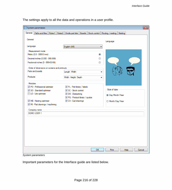
Interface Guide
Page 216 of 228
The settings apply to all the data and operations in a user profile.
System parameters Important parameters for the Interface guide are listed below.

Interface Guide
Page 217 of 228
Measurement mode - millimetres - decimal inches - fractional inches Millimetres are the standard metric measure to one decimal place. e.g.1230.5mm 96.5mm Decimal inches are inches expressed as decimals. e.g. 60.125 in. 12.500 in. Fractional inches are inches expressed as imperial fractions. e.g. 3-1/4 in. 25-3/16 in. Enter fractional inches in the style 99-99/99. The measurement mode is usually the same measurement mode as the saw, machining centre or other machinery. Path for import data System parameter to set directory containing data for import For example:- C:\VER\IMPORT If the path does not exist the program prompts to create the path. Note - if the path contains names of two or more directories that do not exist the program does not create the directories Typical data to import are part lists, board lists and product requirements. Path for Export data System parameter to set directory used by program for exporting data to For example:- C:\VER\EXPORT If the path does not exist the program prompts to create the path

Interface Guide
Page 218 of 228
Note - if the path contains names of two or more directories that do not exist the program does not create the directories Data available for export:-
Summaries Part and product costing data Operations and fittings Cutting list
There are separate paths for import and export so files can be imported from one directory and exported to another. - The choice of layout and data exported are set in the Review runs - Parameters ('Exported' button) Create data for Generate extra data for reports Some data and reports are only available with the appropriate module - no extra data - cutting times - offcuts - cutting dimensions - edging - part drawings - transfer part drawings to saw - destacking - baseboard cutting list - exported cutting list (parts only) - exported cutting list (parts and boards) - convert destack data for Cadmatic (BSB/SDS) Lite - cutting dimensions are created automatically - no need to set a value for this parameter. The program uses the extra data when producing reports, such as, the offcut, edging, and destacking summaries. Only select those items you need as this speeds up the operation of the program. For example, if not making use of offcuts there is no need to create the data for the offcut report.

Interface Guide
Page 219 of 228
- Check all the options required Note - For cutting length value on the Management summary select Cutting times Order of dimensions Length Width Width Length 540.0 345.5 345.5 540.0 240.0 682.0 682.0 250.0 921.0 750.0 750.0 821.0 The part 'Dimensions' are the Length and Width of the part. Set this parameter to choose which order the length and width columns appear on the screen. - Length Width - Width Length In Europe most lists of sizes appear in the order Length-Width but the order Width-Length is more frequently used in the USA and Canada. The order applies wherever the part length and width are displayed e.g. Board library, Part list, Review runs reports. Export cutting list format Set the format for exported cutting lists. The formats available are.- Export format Max parts Max boards DOS Lite 60 50 V6 / Windows Lite 250 200 Cut Planner 100 20 Optisave 225 20 PNX/BDX 2000 200 PNX/BDX 250 200 The columns 'Max. Parts' and 'Max. Boards' show the maximum values for part and board lists for each format. The software automatically divides lists that have more than the maximum parts into smaller units. Control the maximum number of board types by editing the board list or board library. - For the 'Optisave' format the length of each information box is limited to 30 characters.

Interface Guide
Page 220 of 228
Also set the System parameter: Create data for so that exported data is created. If lists are divided the type of division is set in: System parameters

Interface Guide
Page 221 of 228
Import parameters These control the type of import for parts, patterns and boards. They are available at the Import dialog (e.g. File - Import parts). Then select: File - Parameters.
Import parameters
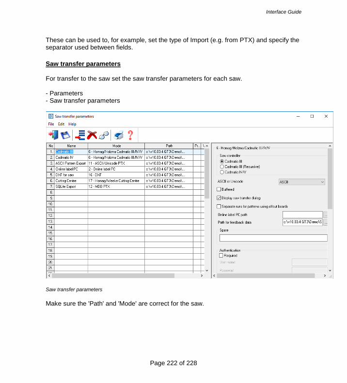
Interface Guide
Page 222 of 228
These can be used to, for example, set the type of Import (e.g. from PTX) and specify the separator used between fields. Saw transfer parameters For transfer to the saw set the saw transfer parameters for each saw. - Parameters - Saw transfer parameters
Saw transfer parameters Make sure the 'Path' and 'Mode' are correct for the saw.

Interface Guide
Page 223 of 228
Information boxes Where the data for parts includes extra information such as detailed edging data, tracking numbers, finished sizes etc. make sure that the Information boxes are correctly set up to cope with the incoming data for import. Use the Information box parameters for this. Add pre-defined or user defined boxes as necessary.
Information boxes Take care when changing these parameters since they apply to all part lists. It is often OK to add new items but deleting or changing an existing item may cause a problem with part lists already using that item.

Interface Guide
Page 224 of 228
Part list import parameters Where data is imported from an external file use the 'Part list import' parameters to define that file format so that it can be correctly imported by the program.
Part list import parameters This sets up the link between the fields in the external file and the fields in the part list including information boxes.

Interface Guide
Page 225 of 228
Machining centre parameters Where transfer to a machining centre is involved make sure that the Machining centre is correctly described in the Machining centre parameters (Main screen - Parameters - Machining centre parameters)
Machining centre parameters Click on a tab for each set of parameters.

Interface Guide
Page 226 of 228
Nesting parameters These are used with the Nesting optimisers. They describe the constraints on the nesting machinery and operation.
Nesting parameters These are used instead of the Optimising parameters for the Nesting optimisers. There are also some System parameters that need to be set for Nesting.

Interface Guide
Page 227 of 228
Nesting also uses the Machining centre parameters to describe the Machining centre. Limits and maximum sizes The following list shows the most important limits on list sizes, field lengths etc. These limits apply to the Professional Optimiser. Item Limit Max items in part list 20000 Max items in cutting list 20000 Max items in board list 5000 Max items in cutting list per optimization (saw) 9999 Max items in cutting list per optimization (nesting) 4000 Max items in board list per optimization (saw) 5000 Max items in board list per optimization (nesting) 2000 Max material types per run(saw) 5000 Max material types per run(nesting) 2000 Max offcuts in run 7500 Max patterns in run (saw) 5000 Max patterns in run (nesting) 2000 Max dimension for parts and board (mm) 9999 Max parts in a pattern (saw) 5000 Max shapes in a nested pattern 1000 Max value for quantity part / board list 99999 Max run quantity per pattern 99999 Max runs in batch 250 Max length of product code 25 Max length of part code 50 Max length of material code 50 Max length of material code (edging library) 50 Max length of board code 25 Max length of edge code 50 Max length of destacking code 50 Max length of machining code 50 Max length of drawing code 25 Max length of pattern code 20 Max length of machine drawing file ref 9 Max length of run number 8 Max length of Order or Allocation code 8 Max length for Stock order number 8 Max length of variable name 25 Max length of formula name 25 Max length of part description (part library) 25 Max length of product description (prod. library) 25 Max length of memo field (product library) 100 Max. records in product library 99999 Max. records in material library 99999 Max. capacity of Board library Access mdb Max. records in order library 99999 Max. records in stock allocations library 99999

Interface Guide
Page 228 of 228
Max. records in orders library 99999 Max. records in edging library. 99999 Max. records in destacking library 99999 Max. records in part library 99999 Max items in variables table 2000 Max items in formula table 5000 Max items in lookup table 5000 Max items in product definition. 500 Max sub-assembly items in product (inc above) Max variables in product definition 500 Max global variables in product definition. 100 Max length of product inf. in req. list 50 Max number of information boxes 99 Max length of information box data 200 Max length of information box title 30 Max length of formula - general 80 Max length of formula - formula table 300 Max length of file names 50 Max items in Quotes/Orders list 999 Max items in Requirements list 999 Max length of file name 50 Max length of path 150 Max length of file extension 4