Embed Size (px)
Citation preview

Versa-Spray� Cable-FedAutomatic Electrostatic
Powder Spray Gun
Manual No. 31-13 � P/N 108 129E
NORDSON CORPORATION � AMHERST, OHIO � USA
� 1994 Nordson CorporationAll Rights Reserved
108 129Issued 3/94
Manual No. 31-13
Notice
This is a Nordson Corporation publication which is protected by copyright. Original copyright date 1990. No partof this document may be photocopied, reproduced, or translated to another language without the prior written
consent of Nordson Corporation. The information contained in this publication is subject to change without notice.
Trademarks
100 Plus, Blue Box, ChromaFlex, CleanSleeve, CleanSpray, Cross-Cut, Easy Coat, Econo-Coat, Flexi-Spray,Flow Sentry, FoamMix, Isocoil, Isocore, Iso-Flo, Nordson, PRX, Pro-Flo, RBX, Ready-Coat, Rhino, Select Coat,
Shur-Lok, Smart Spray, System Sentry, Thread Coat, Tribomatic, and Versa-Spray areregistered trademarks of Nordson Corporation.
CPX, CanWorks, Control Coat, Excel 2000, PowderGrid, Pulse Spray, SCF, Select Cure, Versa-Coat, Versa Screen, and Package of Values are trademarks of Nordson Corporation.
Viton is a registered trademark of E.I. DuPont de Nemours and Company.
Tivar is a registered trademark of Poly-Hi Corporation.

iIntroduction
� 1994 Nordson CorporationAll Rights Reserved
108 129Issued 3/94
Manual No. 31-13
Table of Contents
1. Description 1. . . . . . . . . . . . . . . . . . . . . . . . . . . . . . . . . . . . . . . . . . . . . . . . . .
Standard Versions 1. . . . . . . . . . . . . . . . . . . . . . . . . . . . . . . . . . . . . . . . .
Options 1. . . . . . . . . . . . . . . . . . . . . . . . . . . . . . . . . . . . . . . . . . . . . . . . . . .
2. Installation 2. . . . . . . . . . . . . . . . . . . . . . . . . . . . . . . . . . . . . . . . . . . . . . . . . . .
Installing Optional 32mm Conical Nozzle 3. . . . . . . . . . . . . . . . . . . . . .
Air Supply 4. . . . . . . . . . . . . . . . . . . . . . . . . . . . . . . . . . . . . . . . . . . . . . . . .
3. Operation 5. . . . . . . . . . . . . . . . . . . . . . . . . . . . . . . . . . . . . . . . . . . . . . . . . . . .
Start Up 5. . . . . . . . . . . . . . . . . . . . . . . . . . . . . . . . . . . . . . . . . . . . . . . . . . .
Shutdown 6. . . . . . . . . . . . . . . . . . . . . . . . . . . . . . . . . . . . . . . . . . . . . . . . .
4. Preventive Maintenance 7. . . . . . . . . . . . . . . . . . . . . . . . . . . . . . . . . . . . . . .
Daily 7. . . . . . . . . . . . . . . . . . . . . . . . . . . . . . . . . . . . . . . . . . . . . . . . . . . . .
Periodically 7. . . . . . . . . . . . . . . . . . . . . . . . . . . . . . . . . . . . . . . . . . . . . . . .
5. Troubleshooting 9. . . . . . . . . . . . . . . . . . . . . . . . . . . . . . . . . . . . . . . . . . . . . .
6. Disassembly and Repair 11. . . . . . . . . . . . . . . . . . . . . . . . . . . . . . . . . . . . . .
Powder Path 11. . . . . . . . . . . . . . . . . . . . . . . . . . . . . . . . . . . . . . . . . . . . .
Cleaning and Repair 12. . . . . . . . . . . . . . . . . . . . . . . . . . . . . . . . . . . . . . .
Replacing Cable And Resistor 12. . . . . . . . . . . . . . . . . . . . . . . . . . . . . .
Replacing Cable Assembly 12. . . . . . . . . . . . . . . . . . . . . . . . . . . . . . . . .
Replacing Resistor Assembly 13. . . . . . . . . . . . . . . . . . . . . . . . . . . . . . .
Replacing Electrode 14. . . . . . . . . . . . . . . . . . . . . . . . . . . . . . . . . . . . . . .
7. Parts Lists 15. . . . . . . . . . . . . . . . . . . . . . . . . . . . . . . . . . . . . . . . . . . . . . . . . .
Using The Parts Lists 15. . . . . . . . . . . . . . . . . . . . . . . . . . . . . . . . . . . . . .
Reference Numbers 15. . . . . . . . . . . . . . . . . . . . . . . . . . . . . . . . . . . . . . .
Notes 15. . . . . . . . . . . . . . . . . . . . . . . . . . . . . . . . . . . . . . . . . . . . . . . . . . . .
Part Numbers 15. . . . . . . . . . . . . . . . . . . . . . . . . . . . . . . . . . . . . . . . . . . .
Descriptions 15. . . . . . . . . . . . . . . . . . . . . . . . . . . . . . . . . . . . . . . . . . . . . .
Quantities 15. . . . . . . . . . . . . . . . . . . . . . . . . . . . . . . . . . . . . . . . . . . . . . . .
Gun Assembly Parts List 17. . . . . . . . . . . . . . . . . . . . . . . . . . . . . . . . . . .
Resistor Service Kit 18. . . . . . . . . . . . . . . . . . . . . . . . . . . . . . . . . . . . . . .

ii Introduction
� 1994 Nordson CorporationAll Rights Reserved
108 129Issued 3/94
Manual No. 31-13
Table of Contents (contd.)
Optional Flat Spray Nozzles 19. . . . . . . . . . . . . . . . . . . . . . . . . . . . . . . .
2.5 mm Flat Spray Nozzle 19. . . . . . . . . . . . . . . . . . . . . . . . . . . . . . . . . .
3 mm Flat Spray Nozzle 19. . . . . . . . . . . . . . . . . . . . . . . . . . . . . . . . . . .
4 mm Flat Spray Nozzle 20. . . . . . . . . . . . . . . . . . . . . . . . . . . . . . . . . . .
6 mm Flat Spray Nozzle 20. . . . . . . . . . . . . . . . . . . . . . . . . . . . . . . . . . .
Optional Cross-Cut Nozzles 21. . . . . . . . . . . . . . . . . . . . . . . . . . . . . . . .
60_ Cross-Cut Nozzle 21. . . . . . . . . . . . . . . . . . . . . . . . . . . . . . . . . . . . .
90_ Cross-Cut Nozzle 21. . . . . . . . . . . . . . . . . . . . . . . . . . . . . . . . . . . . .
Optional Castle Nozzle 22. . . . . . . . . . . . . . . . . . . . . . . . . . . . . . . . . . . .
Optional 32 mm Conical Nozzle 23. . . . . . . . . . . . . . . . . . . . . . . . . . . . .
Optional 150 mm and 300 mm Lance Extensions Parts Lists 25. . . .
Optional Deflectors and Hose Adapter 26. . . . . . . . . . . . . . . . . . . . . . .
Gun Mounting Bar 27. . . . . . . . . . . . . . . . . . . . . . . . . . . . . . . . . . . . . . . .
Powder Feed Tubing 27. . . . . . . . . . . . . . . . . . . . . . . . . . . . . . . . . . . . . .
Automatic Purge Adapter Kit 27. . . . . . . . . . . . . . . . . . . . . . . . . . . . . . . .
Adapter, Purge, Versa-Spray 28. . . . . . . . . . . . . . . . . . . . . . . . . . . . . . .
Low-flow Purge Adapter Inlet (Optional) 29. . . . . . . . . . . . . . . . . . . . . .
Index 31. . . . . . . . . . . . . . . . . . . . . . . . . . . . . . . . . . . . . . . . . . . . . . . . . . . . . . . . .
General Safety Precautions Manual 30-1. . . . . . . . . . . . . . . . . . . . . . . . . . . .Appendix
Description 1
� Nordson Corporation 1994All Rights Reserved 108 129
Issued 3/94
Manual No. 31−13
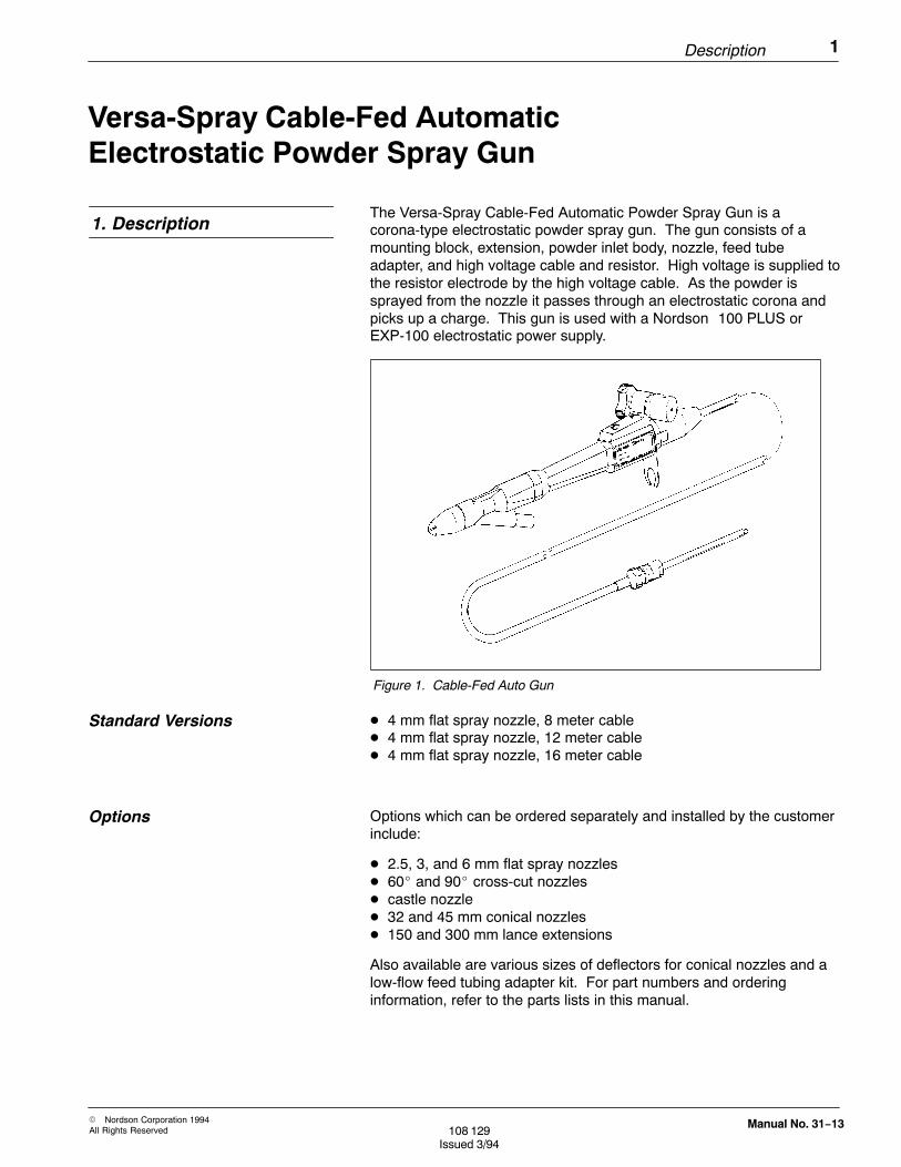
Versa-Spray Cable-Fed AutomaticElectrostatic Powder Spray Gun
The Versa-Spray Cable-Fed Automatic Powder Spray Gun is acorona-type electrostatic powder spray gun. The gun consists of amounting block, extension, powder inlet body, nozzle, feed tubeadapter, and high voltage cable and resistor. High voltage is supplied tothe resistor electrode by the high voltage cable. As the powder issprayed from the nozzle it passes through an electrostatic corona andpicks up a charge. This gun is used with a Nordson 100 PLUS orEXP-100 electrostatic power supply.
Figure 1. Cable-Fed Auto Gun
� 4 mm flat spray nozzle, 8 meter cable� 4 mm flat spray nozzle, 12 meter cable� 4 mm flat spray nozzle, 16 meter cable
Options which can be ordered separately and installed by the customerinclude:
� 2.5, 3, and 6 mm flat spray nozzles� 60� and 90� cross-cut nozzles� castle nozzle� 32 and 45 mm conical nozzles� 150 and 300 mm lance extensions
Also available are various sizes of deflectors for conical nozzles and alow-flow feed tubing adapter kit. For part numbers and orderinginformation, refer to the parts lists in this manual.
1. Description
Standard Versions
Options

2 Installation
� Nordson Corporation 1994All Rights Reserved108 129
Issued 3/94
Manual No. 31−13
1. Install the gun onto a 5/8 in. (15 mm) mounting bar and secure themounting bar to a stationary gun stand or reciprocator arm.
WARNING: This gun can only be used with the cables listed inthis manual, and only with a 100 PLUS or EXP-100 powersupply. Unauthorized modifications or substitutions will voidyour equipment warranty and any agency approvals, andcould cause personal injury or property damage.
2. Connect powder feed tubing to the tubing adapter on the bottom ofthe powder inlet body.
Establish a protected path for the powder feed tubing andelectrostatic cable from the gun to the powder pump andelectrostatic power supply. Make sure that the tubing and cablecannot be abraded, cut, or run over by heavy equipment such asforklift trucks.
Mount gun on 5/8” mounting bar.
Secure cableand feed tubing tomounting bar. Allowslack for movement.
Install end inpower supplymultiplier well.
Install tubingover adapter andsecure with clamp.
Figure 2. Gun Installation
2. Installation
Installation 3
� Nordson Corporation 1994All Rights Reserved 108 129
Issued 3/94
Manual No. 31−13
The electrostatic cable should not be bent in a radius of less than 6inches (152 mm), nor subjected to any strain. Use elastic bands orcable ties to secure the cable and tubing to the mounting bar andreciprocator arm, if used, so that any strain is taken up by thetubing, not the cable.
3. Connect powder feed tubing to the powder pump. Wrap spiral-cuttubing around the feed tubing wherever necessary to prevent itfrom kinking.
NOTE: To increase powder flow and keep distribution as even aspossible, the powder feed tubing should be kept short. Ideally, thetubing should not be longer than 26 ft (8 meters).
4. Connect the high voltage cable to the electrostatic power supply,as described in your power supply manual. Make sure the cableend is clean and dry before connecting.
WARNING: The electrostatic equipment in itself is safe.However, metal objects in the spray area that are isolatedfrom ground accept and store an electrical charge and canbecome unsafe. Ungrounded workpieces present a firehazard and also lose transfer efficiency. For these reasons,all objects and the work in the spray area MUST BEPROPERLY GROUNDED.
1. Remove the flat spray nozzle and the flat spray wear sleeve fromthe gun.
2. Install the conical wear sleeve over the electrode and resistorassembly. Be careful not to bend the electrode. DO NOT use theconical nozzle without the wear sleeve.
3. Ensure that the O-rings are in place on the nozzle. Press thenozzle into the end of the gun with a slight twisting motion until thenozzle bottoms out.
CAUTION: The electrode has a very sharp tip. Install thedeflector by its edges only. DO NOT push the deflector ontothe resistor with your palm. Personal injury may result.
4. Install the conical deflector over the resistor. The deflector shouldbottom out on the wear sleeve.
5. Slide the pattern adjuster sleeve onto the nozzle, with the hole inthe sleeve towards the mounting block end of the gun.
6. Slip the end of the adjuster rod under the pattern adjuster sleeve,so that the rounded pin on the end of the adjuster rod goes into thehole in the sleeve.
Installation (contd.)
Installing Optional 32 mmConical Nozzle
4 Installation
� Nordson Corporation 1994All Rights Reserved108 129
Issued 3/94
Manual No. 31−13
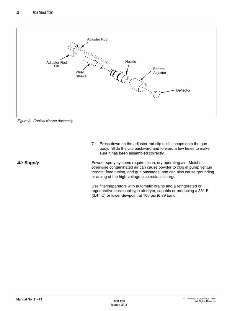
Adjuster Rod
Adjuster RodClip
WearSleeve
Nozzle
PatternAdjuster
Deflector
Figure 3. Conical Nozzle Assembly
7. Press down on the adjuster rod clip until it snaps onto the gunbody. Slide the clip backward and forward a few times to makesure it has been assembled correctly.
Powder spray systems require clean, dry operating air. Moist orotherwise contaminated air can cause powder to clog in pump venturithroats, feed tubing, and gun passages, and can also cause groundingor arcing of the high-voltage electrostatic charge.
Use filter/separators with automatic drains and a refrigerated orregenerative desiccant-type air dryer, capable or producing a 38� F(3.4� C) or lower dewpoint at 100 psi (6.89 bar).
Air Supply

Operation 5
� Nordson Corporation 1994All Rights Reserved 108 129
Issued 3/94
Manual No. 31−13
WARNING: Read and heed the warnings and cautions givenin Manual No. 30-1, General Safety Precautions for PowderSystems and Equipment, before operating this equipment.
1. Turn ON the system electrical power and air supply.
2. Turn ON the booth exhaust fans.
3. Fill the feed hopper 2/3 full with clean, dry powder. Start fluidizingair and adjust to the pressure recommended for your hopper(typically 10-15 psi [0.7-1.0 bar]). Allow time for the powder tobecome completely fluidized before spraying.
WARNING: Breathing finishing powders may be hazardous toyour health. Obtain and read the Material Data Safety Sheetsfor the powders you are using. Wear appropriate respiratoryprotection when handling or spraying powder.
4. Turn ON the electrostatic power supply main power switch. Do notturn on the high voltage until air pressures are set.
5. Adjust pump air pressures:
Atomizing: 30 psi (2.1 bar)
Flow Rate: 20 psi (1.4 bar)
NOTE: Flow rate air pressure controls the volume and velocity of thepowder and air mixture delivered to the gun. Atomizing air pressurecontrols the density (powder-to-air ratio) and velocity of the mixture.The pressures given above are average starting points. Pressures willvary due to required film build, line speed, and part configuration.Adjust air pressures to obtain desired results.
6. Test spray pattern and adjust air pressures and pattern sleeve, ifused, as necessary.
7. Turn ON the high voltage at the electrostatic power supply. Adjustto 100 kV.
3. Operation
Start Up
6 Operation
� Nordson Corporation 1994All Rights Reserved108 129
Issued 3/94
Manual No. 31−13
8. Test spray workpieces. Adjust the air pressures and kV output toachieve desired results.
If using a master control unit to control multiple guns and powersupplies, the power supply high voltage and main switches can be lefton after initial startup adjustments are made. Turning the mastercontrol on will then trigger pump air and high voltage.
WARNING: When gun is being controlled by a master controlunit, turn OFF high voltage and main switches at the powersupply and ground gun electrode, before removing gun fromservice for repairs.
1. Turn OFF the power supply high voltage and main switches. Ifyour system uses multiple guns controlled by a master control unit,turn OFF power at the master control unit to shut down all theguns.
2. Disassemble and clean the gun powder paths and pumps. Blowout the feed tubing, from the pump into the booth (make sureexhaust fans are running). Replace worn parts.
Perform daily maintenance as described in your component and systemmanuals.
For information on the operation of other components of your system,refer to their respective manuals.
Start Up (contd.)
Shutdown
Preventive Maintenance 7
� Nordson Corporation 1994All Rights Reserved 108 129
Issued 3/94
Manual No. 31−13
1. Remove the gun from the mounting bar.
2. Disconnect the powder feed tubing from the pump and gun andleave the gun end in the booth.
3. Make sure exhaust fans are running. Blow out the feed tubing,from the pump end into the booth. NEVER blow powder back-wards into the pump.
4. Disassemble the gun’s powder path and blow clean with lowpressure compressed air.
5. Wipe parts with a clean, dry cloth and replace worn parts. Ifimpact-fused powder has built up on contact surfaces, clean offcarefully with a wooden dowel or similiar tool. Never use sharpobjects to clean parts coming in contact with the powder stream.Scratches in the surfaces will allow powder to build up and fuse,clogging the gun.
NOTE: If necessary, use a cloth dampened with isopropyl or ethylalcohol to clean parts. Remove O-rings before cleaning. Use alcoholsparingly, as a last resort. DO NOT immerse guns in alcohol. DO NOTuse other solvents.
6. Clean the spray booth as described in your booth or systemmanual.
WARNING: Before performing the following procedure, shutoff all electrical power at a disconnect switch or breaker aheadof the power supply or master control module. Ground theelectrode before removing the gun from the mounting bar.Wait three minutes after shutting off power supply beforeremoving cable from multiplier well.
Measure the resistance of the high voltage cable and gun resistor witha megohm meter. If your readings are not in the proper range, replacethe component. The resistance of the cable and the gun resistor limitthe amperage at the gun electrode to safe levels. If this resistancebreaks down, the amperage at the electrode could increase enough tocause electrical shock, fire, or explosion. Failure of the cable or gunresistor will cause a loss of powder wrap and poor coating efficiency.
1. Disconnect cable assembly from electrostatic power supply andmeasure the resistance, from cable end to gun electrode.
Resistance of cable assembly should be:332 to 456 M, at 500 volts.
4. Preventive Maintenance
Daily
Periodically

8 Preventive Maintenance
� Nordson Corporation 1994All Rights Reserved108 129
Issued 3/94
Manual No. 31−13
2. If the cable assembly resistance does not meet specifications,remove the resistor kit from the cable and measure the resistancefrom the electrode to the end of the resistor.
Resistance of gun resistor should be:153 -187 Mat 500 volts.
Replace the gun resistor with a new resistor kit if the reading is notwithin the specified range. Otherwise, replace the entire cableassembly with a new 8, 12, or 16 meter cable kit, which includes aresistor kit installed on the cable and ready to install in the gun.
When replacing the gun resistor or cable assembly, refer to the sectionin this manual on gun disassembly and repair.
Periodically (contd.)
Troubleshooting 9
� Nordson Corporation 1994All Rights Reserved 108 129
Issued 3/94
Manual No. 31−13
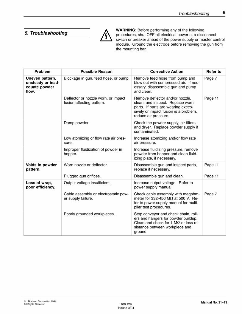
WARNING: Before performing any of the followingprocedures, shut OFF all electrical power at a disconnectswitch or breaker ahead of the power supply or master controlmodule. Ground the electrode before removing the gun fromthe mounting bar.
Problem Possible Reason Corrective Action Refer to
Uneven pattern,unsteady or inad-equate powderflow.
Blockage in gun, feed hose, or pump. Remove feed hose from pump andblow out with compressed air. If nec-essary, disassemble gun and pumpand clean.
Page 7
Deflector or nozzle worn, or impactfusion affecting pattern.
Remove deflector and/or nozzle,clean, and inspect. Replace wornparts. If parts are wearing exces-sively or impact fusion is a problem,reduce air pressure.
Page 11
Damp powder Check the powder supply, air filtersand dryer. Replace powder supply ifcontaminated.
Low atomizing or flow rate air pres-sure.
Increase atomizing and/or flow rateair pressure.
Improper fluidization of powder inhopper.
Increase fluidizing pressure, removepowder from hopper and clean fluid-izing plate, if necessary.
Voids in powderpattern.
Worn nozzle or deflector. Disassemble gun and inspect parts,replace if necessary.
Page 11
Plugged gun orifices. Disassemble gun and clean. Page 11
Loss of wrap,poor efficiency.
Output voltage insufficient. Increase output voltage. Refer topower supply manual.
Cable assembly or electrostatic pow-er supply failure.
Check cable assembly with megohm-meter for 332-456 M at 500 V. Re-fer to power supply manual for multi-plier test procedures.
Page 7
Poorly grounded workpieces. Stop conveyor and check chain, roll-ers and hangers for powder buildup.Clean and check for 1 Mor less re-sistance between workpiece andground.
5. Troubleshooting
10 Troubleshooting
� Nordson Corporation 1994All Rights Reserved108 129
Issued 3/94
Manual No. 31−13
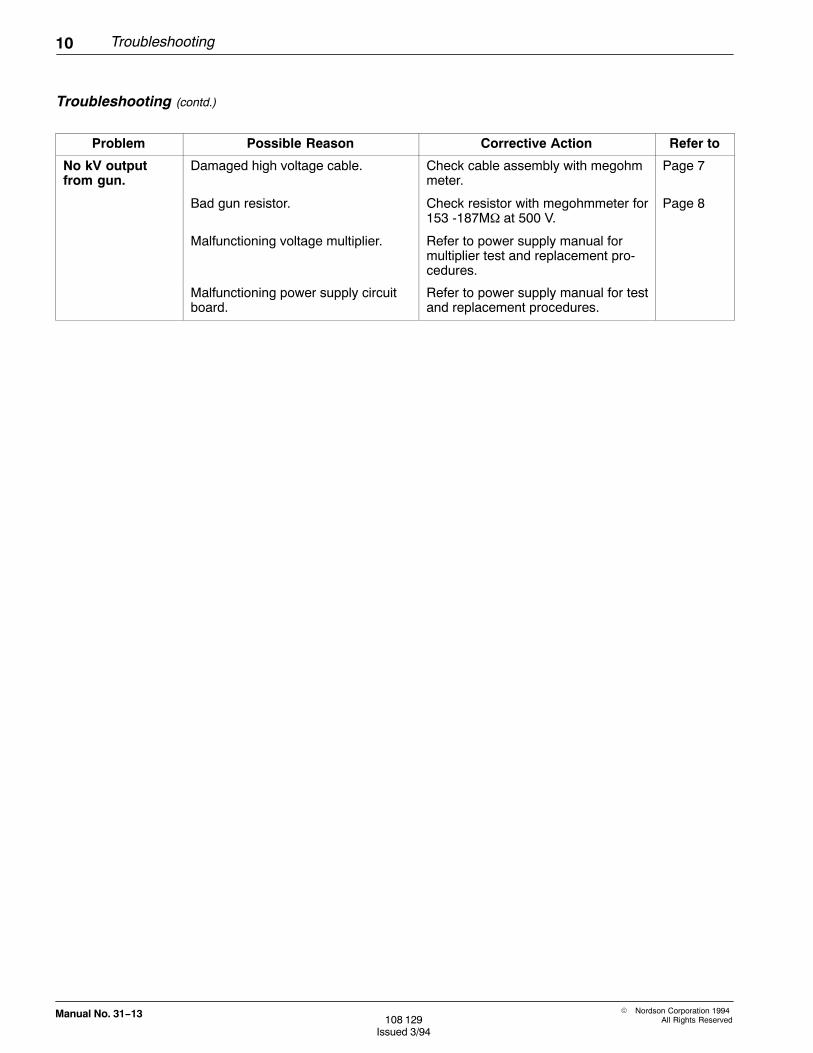
Problem Possible Reason Corrective Action Refer to
No kV outputfrom gun.
Damaged high voltage cable. Check cable assembly with megohmmeter.
Page 7
Bad gun resistor. Check resistor with megohmmeter for153 -187Mat 500 V.
Page 8
Malfunctioning voltage multiplier. Refer to power supply manual formultiplier test and replacement pro-cedures.
Malfunctioning power supply circuitboard.
Refer to power supply manual for testand replacement procedures.
Troubleshooting (contd.)

Disassembly and Repair 11
� Nordson Corporation 1994All Rights Reserved 108 129
Issued 3/94
Manual No. 31−13
WARNING: Before attempting any of the followingprocedures, shut OFF all power at a disconnect switch orbreaker ahead of the power unit or master control module.Ground the electrode before removing the gun from themounting bar.
1. Remove the gun from the mounting bar by loosening the knurledknob on the gun mount. Disconnect the powder feed hose.
2. Remove the nozzle from the powder inlet body, rotating the nozzlewhile pulling it out. Remove the wear sleeve from the resistorprobe.
3. Remove the hose adapter from the powder inlet body.
4. Loosen the setscrew on the underside of the powder inlet body andremove the powder inlet body from the gun.
Figure 4. Disassembling Powder Path
Flat Spray Nozzle
Powder Inlet Body
WearSleeve
Resistor Holder
Tube Adapter
Set Screw
6. Disassembly and Repair
Powder Path

12 Disassembly and Repair
� Nordson Corporation 1994All Rights Reserved108 129
Issued 3/94
Manual No. 31−13
Cleaning and Repair
1. Clean all powder path parts with compressed air and a clean cloth.DO NOT use a knife or any other sharp object to scrape off impactfusion (powder fused to inside surfaces). Powder will quickly buildup in any surface scratches.
NOTE: If necessary, use a cloth dampened with isopropyl or ethylalcohol to clean parts. Remove O-rings before cleaning. Use alcoholsparingly, as a last resort. DO NOT immerse guns in alcohol. DO NOTuse other solvents.
2. Inspect all O-rings and replace if damaged.
3. Inspect all gun parts. Replace worn parts as necessary.
Reverse the disassembly procedure to re-assemble the powder pathcomponents.
The high voltage cable and gun resistor can be replaced with a newcable service kit, or the gun resistor can be replaced separately.
WARNING: Before performing the following procedures, shutOFF all electrical power at a disconnect switch or breakerahead of the power supply or master control module. Groundthe electrode before removing the gun from the mounting bar.
Replacing Cable Assembly
1. Remove the gun from the mounting bar. Remove the nozzleassembly from the powder path and unscrew the cable from thegun extension.
2. Disconnect the cable from the electrostatic power supply. Discardthe cable assembly.
3. Remove the new cable assembly from box, carefully uncoil it, androute from power supply to gun.
4. Install the resistor end of the cable assembly in the gun, beingcareful not to bend the electrode, and thread the cable assemblyinto the gun extension. Re-install the nozzle assembly.
5. Connect the cable to the power supply multiplier, as described inyour power supply manual. The cable end must be clean and dry,and the multiplier well filled with dielectric oil.
Replacing Cable And Resistor

Disassembly and Repair 13
� Nordson Corporation 1994All Rights Reserved 108 129
Issued 3/94
Manual No. 31−13
Replacing Resistor Assembly
1. Remove the gun from the mounting bar. Remove the nozzleassembly from the powder path and unscrew the cable from gunextension.
2. Place one wrench on the spring cover flats and another on thecable adapter flats. Unscrew the cable adapter from the springcover.
NOTE: Thread-locking compound is used on adapter threads duringassembly. If adapter is difficult to remove, use a soft-jawed vise to holdspring cover.
3. Place the coupling flats in a soft-jawed vise, with the contact tip up,and unscrew the cable well. Discard old resistor kit parts.
4. Clean old dielectric grease off cable end. End must be clean anddry.
WARNING: The following steps must be followed to preventresistor failure. All air inside the cable well, resistor holder,and contact must be replaced by dielectric grease when kit isinstalled. Air pockets will cause internal arcing and carbontracking, leading to failure of the cable or resistor.
5. Remove the plastic shipping caps from the ends of the newresistor kit. Unscrew the well adapter (and resistor holder andresistor) from the cable well.
Figure 5. Replacing Resistor Assembly
Electrode Resistor WellAdapter
Coupling
SpringCover
CableAdapter
Cable Well
Resistor Holder
Contact
14 Disassembly and Repair
� Nordson Corporation 1994All Rights Reserved108 129
Issued 3/94
Manual No. 31−13
6. Insert the end of the cable into the externally threaded end of thecable well and slide the well partially over the cable. Place yourthumb over the open end of the cable well and slide the well overthe cable until the well bottoms out on the coupling. Thread thewell into the coupling and finger-tighten. This procedure forcesgrease back around the cable end, eliminating any air pockets.
7. Slide the metal cable adapter over the cable well. Thread the welladapter into the end of the cable well and wipe off the excessgrease.
8. Slide the spring and spring cover up over the coupling. Apply 1-2drops of thread-locking compound to the cable adapter threadsand screw the adapter into the spring cover until it bottoms out.
9. Install the cable assembly into the gun, being careful not to bendelectrode. Thread the cable adapter into the gun and hand-tighten.
10. Re-install nozzle assembly on gun.
Replacing Electrode
To replace a bent or broken electrode:
1. Remove the nozzle assembly.
2. Unscrew the contact from the resistor holder and discard.
3. Apply dielectric grease to the threads of the new contact, and intothe end of the resistor holder. No air pockets are permissible.
4. Screw the new contact into the resistor holder and wipe up excessgrease.
Replacing Resistor Assembly(contd.)

Parts Lists 15
� Nordson Corporation 1994All Rights Reserved 108 129
Issued 3/94
Manual No. 31−13
Reference Numbers
The number in the REF. column indicates the number assigned to thepart in the illustration preceding the list. The code NS means the part isNot Shown in the illustration.
Notes
A letter in the NOTE column refers to a note below the parts list whichgives additional information concerning that part. Special attentionshould be given to noted parts.
Part Numbers
Part numbers are given only for saleable parts or kits. Parts that arenot sold separately are sometimes shown for clarity.
Descriptions
Descriptions are indented to show the relationship between parts forordering purposes. A part indented once is a component of the toplevel assembly, a part indented twice is a component of both the firstone level indented item above it and the top level assembly. Forexample:
Ref. Note Part No. Description Qty.
− 000 000 Top Level Assembly 1
1 A 000 000 � Assembly or Part 2
2 000 000 � � Subassembly or Part 1
If you order item 1, items 2 & 3 will be included.If you order item 2, item 3 will be included.If you order item 3, you will receive item 3 only.
Quantities
Quantities given in all parts lists except recommended spares lists arethe quantities needed to assemble the next level assembly. The code“ASR” (As Required) is used for bulk items such as tubing, which isordered in increments of one foot.
7. Parts Lists
Using The Parts Lists
16 Parts Lists
� Nordson Corporation 1994All Rights Reserved108 129
Issued 3/94
Manual No. 31−13
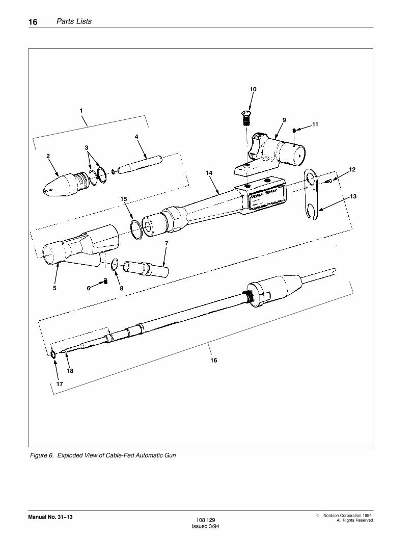
Figure 6. Exploded View of Cable-Fed Automatic Gun
1
23
4
10
911
12
13
14
15
5 6 8
7
16
17
18

Parts Lists 17
� Nordson Corporation 1994All Rights Reserved 108 129
Issued 3/94
Manual No. 31−13
Ref. NoteKit Part
No. Part No. Description Qty.
− 133 399 Gun, Automatic, 8M Cable, Versa-Spray 1
− 133 400 Gun, Automatic, 12M Cable, Versa-Spray 1
− 133 401 Gun, Automatic, 16M Cable, Versa-Spray 1
1 A 134 380 � Service Kit, Nozzle, Flat Spray, 2.5 mm 1
1 B 141 044 � Service Kit, Nozzle, Flat Spray, 4 mm 1
2 141 045 � � Nozzle, Flat Spray, 4 mm, w/O-rings, Tivar 1
3 941 181 � � � O-ring, Silicone, .875 x 1.063 x .094 in. 1
4 134 385 � � Sleeve, Wear, Flat Spray, w/O-ring 1
5 125 612 � Body, Inlet 1
6 982 455 � Screw, Set, M6 x 1.0 x 8, Nylon, Black 1
7 134 386 � Adapter, Hose, w/O-ring 1
8 940 163 � � O-ring, Silicone, .625 x .750 x .063 in. 1
9 133 409 � Mount, Gun, w/Pivot 1
10 981 708 � � Screw, M8 x 1.25 x 20 mm, Black 2
11 982 067 � � Screw, Set, Cup, M5 x 5, Black 2
12 982 187 � Screw, Flat Hd, M3 x 8 1
13 133 417 � Bracket, Tube, Retaining 1
14 − � Extension, Gun, Versa-Spray 1
15 940 243 � O-ring, Silicone, 1.125 x 1.250 x .062 in. 1
16 C 133 423 � Service Kit, 8M Cable 1
16 C 133 424 � Service Kit, 12M Cable 1
16 C 133 425 � Service Kit, 16M Cable 1
17 940 117 � � O-ring, Silicone, .312 x .438 x .063 in. 1
18 132 748 � � Contact, Cable 1
Note A: Guns w/revision B part numbers include 134384 nozzle.
Note B: Guns w/revision C part numbers include 141045 nozzle. This nozzle produces a slightly smaller effec-tive fan pattern, higher film build rate, and increased transfer efficiency.
Note C: Choose one service kit for replacement cable and gun resistor.
Gun Assembly Parts List
18 Parts Lists
� Nordson Corporation 1994All Rights Reserved108 129
Issued 3/94
Manual No. 31−13
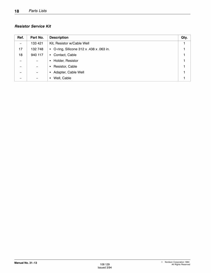
Ref. Part No. Description Qty.
− 133 421 Kit, Resistor w/Cable Well 1
17 132 748 � O-ring, SIlicone 312 x .438 x .063 in. 1
18 940 117 � Contact, Cable 1
− − � Holder, Resistor 1
− − � Resistor, Cable 1
− − � Adapter, Cable Well 1
− − � Well, Cable 1
Resistor Service Kit
Parts Lists 19
� Nordson Corporation 1994All Rights Reserved 108 129
Issued 3/94
Manual No. 31−13
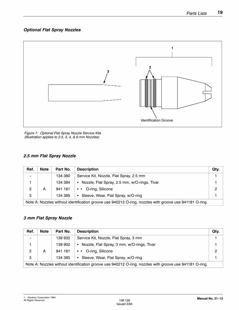
Figure 7. Optional Flat Spray Nozzle Service Kits(Illustration applies to 2.5, 3, 4, & 6 mm Nozzles)
32
1
Identification Groove
Ref. Note Part No. Description Qty.
− 134 380 Service Kit, Nozzle, Flat Spray, 2.5 mm 1
1 134 384 � Nozzle, Flat Spray, 2.5 mm, w/O-rings, Tivar 1
2 A 941 181 � � O-ring, Silicone 2
3 134 385 � Sleeve, Wear, Flat Spray, w/O-ring 1
Note A: Nozzles without identification groove use 940212 O-ring, nozzles with groove use 941181 O-ring.
Ref. Note Part No. Description Qty.
− 139 935 Service Kit, Nozzle, Flat Spray, 3 mm 1
1 139 902 � Nozzle, Flat Spray, 3 mm, w/O-rings, Tivar 1
2 A 941 181 � � O-ring, Silicone 2
3 134 385 � Sleeve, Wear, Flat Spray, w/O-ring 1
Note A: Nozzles without identification groove use 940212 O-ring, nozzles with groove use 941181 O-ring.
Optional Flat Spray Nozzles
2.5 mm Flat Spray Nozzle
3 mm Flat Spray Nozzle
20 Parts Lists
� Nordson Corporation 1994All Rights Reserved108 129
Issued 3/94
Manual No. 31−13
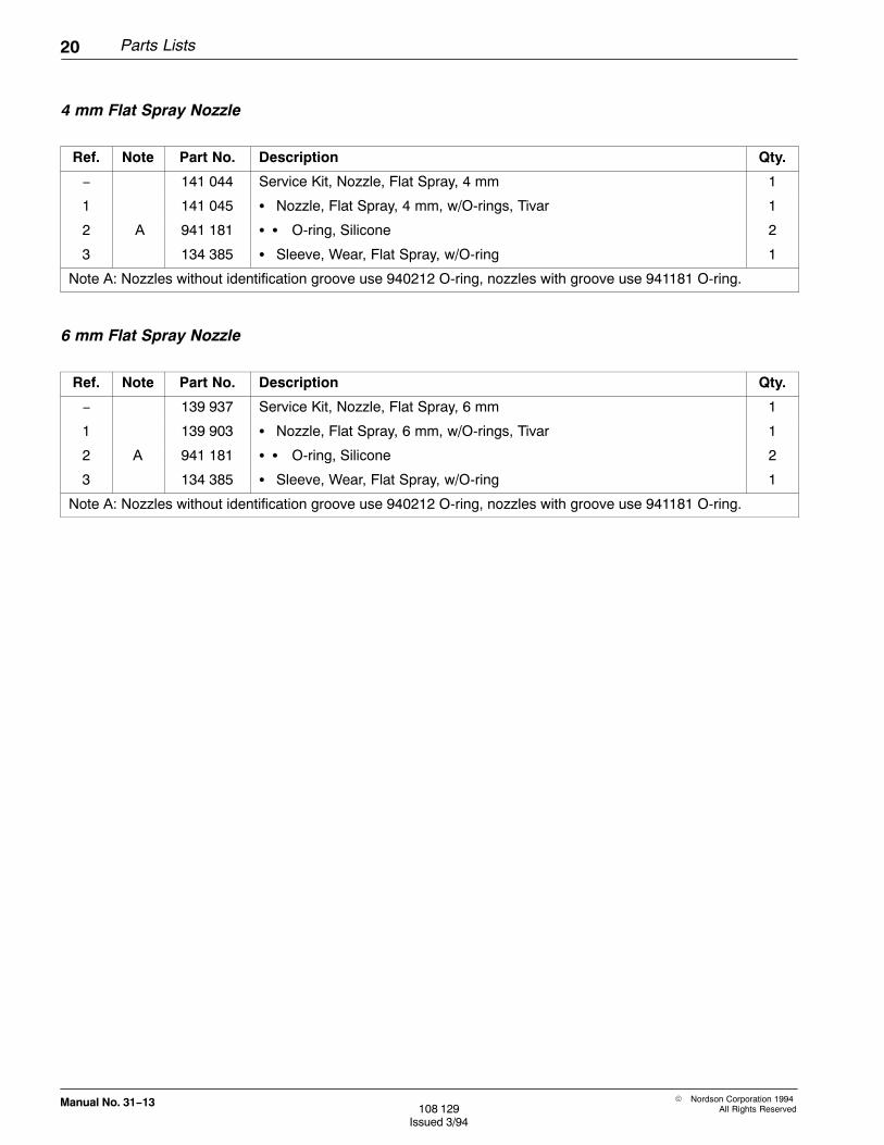
Ref. Note Part No. Description Qty.
− 141 044 Service Kit, Nozzle, Flat Spray, 4 mm 1
1 141 045 � Nozzle, Flat Spray, 4 mm, w/O-rings, Tivar 1
2 A 941 181 � � O-ring, Silicone 2
3 134 385 � Sleeve, Wear, Flat Spray, w/O-ring 1
Note A: Nozzles without identification groove use 940212 O-ring, nozzles with groove use 941181 O-ring.
Ref. Note Part No. Description Qty.
− 139 937 Service Kit, Nozzle, Flat Spray, 6 mm 1
1 139 903 � Nozzle, Flat Spray, 6 mm, w/O-rings, Tivar 1
2 A 941 181 � � O-ring, Silicone 2
3 134 385 � Sleeve, Wear, Flat Spray, w/O-ring 1
Note A: Nozzles without identification groove use 940212 O-ring, nozzles with groove use 941181 O-ring.
4 mm Flat Spray Nozzle
6 mm Flat Spray Nozzle

Parts Lists 21
� Nordson Corporation 1994All Rights Reserved 108 129
Issued 3/94
Manual No. 31−13
32
1
60 DegreeCross-Cut Nozzle
Identification Groove
3 2
1
90 DegreeCross-Cut Nozzle
Figure 8. 60� & 90� Cross-Cut Nozzles
Ref. Note Part No. Description Qty.
− 141 013 Service Kit, Nozzle, Cross-Cut, 60� 1
− 141 017 � Nozzle, Cross-Cut, 60�, w/O-rings 1
2 A 941 181 � � O-ring, Silicone 2
3 134 385 � Sleeve, Wear, Flat Spray, w/O-ring 1
Note A: Nozzles without identification groove use 940212 O-ring, nozzles with groove use 941181 O-ring.
Ref. Note Part No. Description Qty.
− 141 014 Service Kit, Nozzle, Cross-Cut, 90� 1
1 141 015 � Nozzle, Cross-Cut, 90�, w/O-rings 1
2 A 941 181 � � O-ring, Silicone 2
3 134 385 � Sleeve, Wear, Flat Spray, w/O-ring 1
Note A: Nozzles without identification groove use 940212 O-ring, nozzles with groove use 941181 O-ring.
Optional Cross-Cut Nozzles
60� Cross-Cut Nozzle
90� Cross-Cut Nozzle
22 Parts Lists
� Nordson Corporation 1994All Rights Reserved108 129
Issued 3/94
Manual No. 31−13
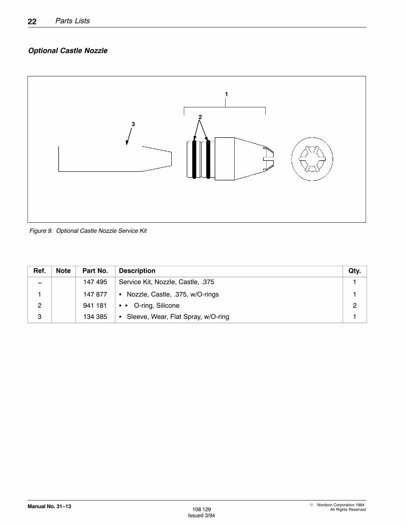
Figure 9. Optional Castle Nozzle Service Kit
32
1
Ref. Note Part No. Description Qty.
− 147 495 Service Kit, Nozzle, Castle, .375 1
1 147 877 � Nozzle, Castle, .375, w/O-rings 1
2 941 181 � � O-ring, Silicone 2
3 134 385 � Sleeve, Wear, Flat Spray, w/O-ring 1
Optional Castle Nozzle

Parts Lists 23
� Nordson Corporation 1994All Rights Reserved 108 129
Issued 3/94
Manual No. 31−13
Figure 10. Optional 32 mm Conical Nozzle
6
4
2
1
5
3
89
7
Ref. Note Part No. Description Qty.
− 134 576 Service Kit, Nozzle, 32 mm, Auto 1
1 A − � Nozzle, 32 mm dia., w/O-rings, Tivar 1
2 A 940 212 � � O-ring, Silicone, .938 x 1.063 x .063 in. 2
3 133 734 � Deflector, 26 mm dia., w/O-ring, Tivar 1
4 132 348 � Sleeve, Wear, Conical, Tivar 1
5 134 580 � Sleeve, Pattern, Versa-Spray 1
6 134 577 � Adjuster, Sleeve 1
Note A: Replaced by the following parts:
7 B 145 558 � Nozzle, 32 mm, w/O-rings 1
8 941 181 � � O-ring, Silicone, .875 x 1.063 x .094 in. 2
9 941 215 � � O-ring, Silicone, 1.062 x 1.250 x .094 in. 1
Note B: New nozzle has larger cross-sectional O-rings (item 8) and additional O-ring (item 9) and groove onlarge O.D.
Optional 32 mm ConicalNozzle
24 Parts Lists
� Nordson Corporation 1994All Rights Reserved108 129
Issued 3/94
Manual No. 31−13
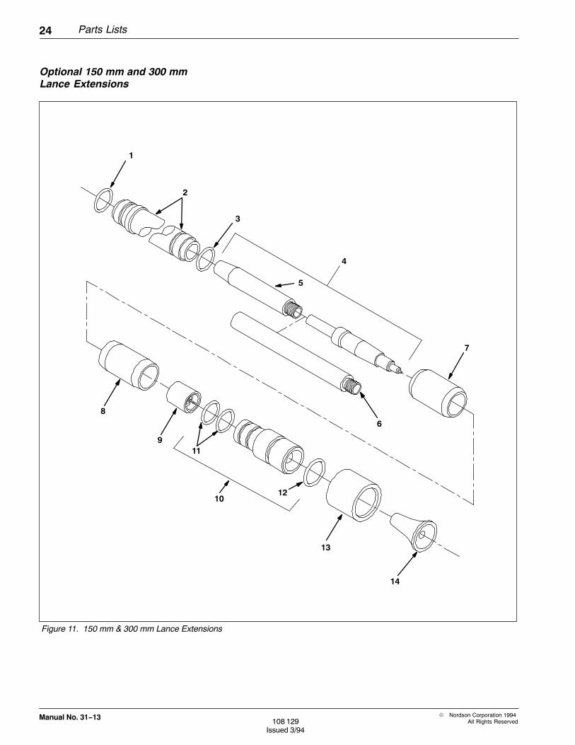
Figure 11. 150 mm & 300 mm Lance Extensions
1
2
3
6
13
5
8
10
11
12
4
9
7
14
Optional 150 mm and 300 mmLance Extensions

Parts Lists 25
� Nordson Corporation 1994All Rights Reserved 108 129
Issued 3/94
Manual No. 31−13
Ref. Note Part No. Description Qty.
− 133 730 Extension, Lance, 150 mm 1
− 133 731 Extension, Lance, 300 mm 1
1 940 212 � O-ring, Silicone, .938 x 1.063 x 063 in. 1
2 133 728 � Tube, Extension, 150 mm 1
2 133 729 � Tube, Extension, 300 mm 1
3 940 224 � O-ring, Silicone, 1.00 x 1.125 x .063 in. 1
4 C 160 066 � Electrode, Lance, 150 mm 1
5 C 160 020 � � Sleeving, Contact 1
4 C 160 068 � Electrode, Lance, 300 mm 1
5 C 160 020 � � Sleeving, Contact 1
6 160 021 � � Link, Apdapter, 300 mm 1
7 133 719 � Support, Lance 1
8 133 721 � Connector, Nozzle 1
9 249 194 � Support, Cable 1
− A − � Nozzle, 32 mm, w/O-rings 1
− A 940 212 � � O-ring, Silicone, .938 x 1.063 x .063 in. 2
− B − � Adjuster, Pattern, w/O-ring 1
− B 940 262 � � O-ring, Silicone, 1.250 x 1.375 x .063 in. 1
10 145 558 � Nozzle, w/O-ring 1
11 941 181 � � O-ring, Silicone 2
12 941 215 � � O-ring, Silicone 1
13 144 759 � Adjuster, Pattern, 26 mm 1
14 133 734 � Deflector, 26 mm, w/O-ring 1
Note A: Obsolete, replaced by item 13, P/N 145558 nozzle.
Note B: Obsolete, replaced by item 16, P/N 144759 pattern adjuster.
Note C: Replaces 133732 electrode, 150 mm and 133733 electrode, 300 mm. Use 130727 sleeve, contact withold style electrodes.
Optional 150 mm and 300 mmLance Extensions Parts Lists

26 Parts Lists
� Nordson Corporation 1994All Rights Reserved108 129
Issued 3/94
Manual No. 31−13
Figure 12. Optional Deflectors and Hose Adapter(Drawing Not To Scale)
2
1
4
3
6
5
8
7
Ref. Part No. Description Qty.
1 135 865 Deflector,14 mm dia., Tivar, w/O-ring 1
2 940 084 � O-ring, Silicone, .188 x .312 x .062 in. 1
3 147 880 Deflector, 16 mm dia., Tivar, w/O-ring 1
4 940 084 � O-ring, Silicone, .188 x .312 x .062 in. 1
5 133 714 Deflector, 19 mm dia., Tivar, w/O-ring 1
6 940 084 � O-ring, Silicone, .188 x .312 x .062 in. 1
7 135 896 Adapter, Hose, Low-Flow, w/O-ring 1
8 940 163 � O-ring, Silicone, .625 x .750 x .063 in. 1
Optional Deflectors and HoseAdapter

Parts Lists 27
� Nordson Corporation 1994All Rights Reserved 108 129
Issued 3/94
Manual No. 31−13
Part No. Description
133 403 Bar, Gun, Mounting
Note: Bulk part numbers, order in one foot increments.
Part No. Description
900 550 Tubing, Powder, High-Flow (1/2 in. I.D.)
900 549 Tubing, Powder, Low-Flow (3/8 in. I.D.)
Figure 13. Automatic Purge Adapter Kit
1
Ref. Note Part No. Description Qty.
1 A 157 094 Adapter, Purge, Hose, Versa-Spray 1
Note A: See page 28 for parts list.
Gun Mounting Bar
Powder Feed Tubing
Automatic Purge Adapter Kit

28 Parts Lists
� Nordson Corporation 1994All Rights Reserved108 129
Issued 3/94
Manual No. 31−13
Figure 14. Versa-Spray Hose Purge Adapter
13
42
Ref. Note Part No. Description Qty.
− 157 094 Adapter, Purge, Hose, Versa-Spray 1
1 − � Adapter, Purge, Outlet 1
2 940 163 � O-ring, Silicone, .625 x .750 x .062 in. 1
3 − � Adapter, Purge, Inlet 1
4 971 675 � Fitting, Swivel, Elbow, 1/4 in. Tubing x 1/4 in. NPT 1
Adapter, Purge, Versa-Spray
Parts Lists 29
� Nordson Corporation 1994All Rights Reserved 108 129
Issued 3/94
Manual No. 31−13
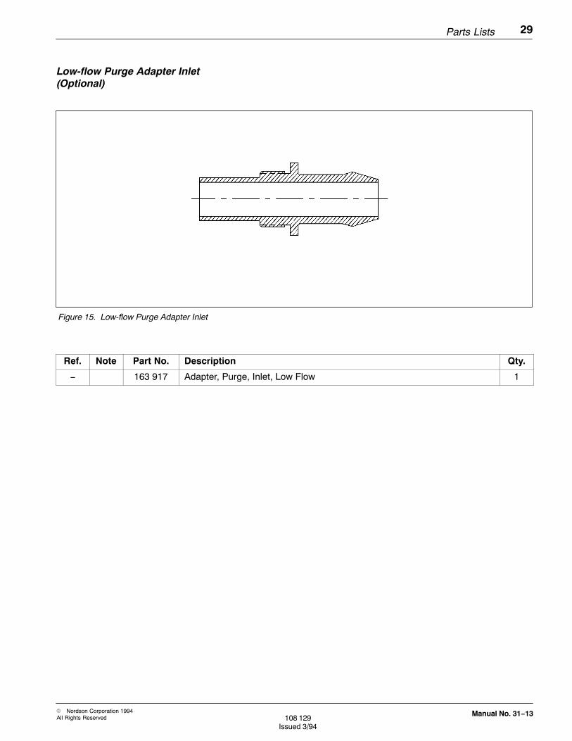
Figure 15. Low-flow Purge Adapter Inlet
Ref. Note Part No. Description Qty.
− 163 917 Adapter, Purge, Inlet, Low Flow 1
Low-flow Purge Adapter Inlet(Optional)
30 Parts Lists
� Nordson Corporation 1994All Rights Reserved108 129
Issued 3/94
Manual No. 31−13
Index 31
� Nordson Corporation 1994All Rights Reserved 108 129
Issued 3/94
Manual No. 31−13
A
AdapterAutomatic Purge Kit, 27Hose, 26Low Flow Purge Inlet, 29Purge, Versa‐Spray, 28
Air Supply, Requirements, 4
D
Deflectors and Hose Adapter, 26
Description, Standard Versions, Options, 1
Disassembly and Repair, 11Powder Path, 11
G
Gun Assembly Parts List, 17
Gun Mounting Bar, 27
I
InstallationConical Nozzle 32 mm, 3Electrostatic Cable, 3Gun Mounting Bar, Powder Feed Tubing, 2
L
Lance Extensions, 150 mm and 300 mm, 24
Low Flow Purge Adapter Inlet, 29
N
Nozzles2.5 mm Flat Spray, 193 mm Flat Spray, 194 mm Flat Spray, 206 mm Flat Spray, 2060 Degree Cross‐Cut, 2190 Degree Cross‐Cut, 21Castle, 22
Conical ‐ 32 mm, 23Cross‐Cut, 21Flat Spray, 19
O
Operation, 5Shutdown, 6Start Up, 5
P
Parts Lists, 15Adapter Kit ‐ Automatic Purge, 27Adapter, Purge, Versa‐Spray, 28Deflectors and Hose Adapter, 26Gun Assembly Parts List, 17Gun Mounting Bar, 27Lance Extensions, 150 mm and 300 mm, 24Low Flow Purge Adapter Inlet, 29Nozzles
2.5 mm Flat Spray, 193 mm Flat Spray, 194 mm Flat Spray, 206 mm Flat Spray, 2032 mm Conical, 2360 Degree Cross‐Cut, 2190 Degree Cross‐Cut, 21Castle, 22Cross‐Cut, 21
Powder Feed Tubing, 27Resistor Service Kit, 18Using The Parts Lists, 15
Powder Feed Tubing, 27
Powder Path, Cleaning and Repair, 12
Preventive Maintenance, 7Daily, 7Periodically, 7
R
ReplacementCable Assembly, 12Electrode, 14Resistor, 13
Resistor Service Kit, 18
S
Shutdown, 6
32 Index
� Nordson Corporation 1994All Rights Reserved108 129
Issued 3/94
Manual No. 31−13
S (contd.)
Start Up, 5
T
Troubleshooting, 9Pattern, 9Poor efficiency, 9