Embed Size (px)
Citation preview
Department of Computer Science and Electrical Engineering
Verilog Case-Statement-Based State Machines
IProf. Ryan Robucci

Basic State MachinesBasic State Machines
S0 S1 S2
a/q0
b/q1
a/q0
b/q2
c/q3
c/q2
S0/q0 S1/q1 S2/q2
a
b
a
b
c
c
a,b,c/q4Mealy Machine
Moore Machine
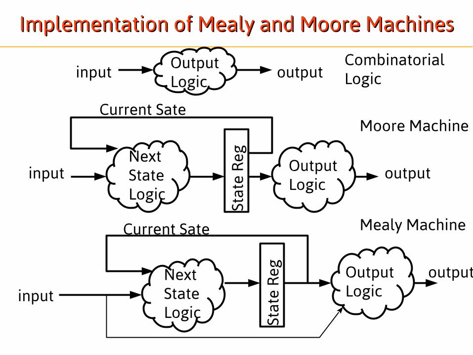
Implementation of Mealy and Moore MachinesImplementation of Mealy and Moore Machines
Stat
e R
eg
OutputLogic
OutputLogic
OutputLogic
NextStateLogic
Next StateLogic
Current Sate
Current Sate
Stat
e R
eg
input
input
input
output
output
output
Mealy Machine
Moore Machine
CombinatorialLogic

State-Machine ImplementationState-Machine Implementation
xi
yi
clkreset
Qi
Qi+1
sequ
enti
al
comb.
All State Machines can be partitioned into a combinatorial and sequential parts. We will often code these two pieces in separate code blocks, but they may also be combined.(Note: simple register operations such a synchronous reset can be coded in either the comb. or the seq. block, but such simple things make sense to be coded in the sequential piece. An asynchronous reset should be part of the seq. block. )

State-Machine ImplementationState-Machine Implementation
module one_hot (clk, rst, x,y); input clk, rst,x; output y; reg [1:0] y; // Declare the symbolic names for states using parameter localparam [6:0] S1 = 7'b0000001,S2 = 7'b0000010, ... S7 = 7'b1000000;
// Declare current state and next state variables reg [2:0] CS,NS; //reg!=register
Code header
Consider more meaningful names,e.g. S_WAIT_FOR_READY, S_INIT

State Register and Logic BehaviorsState Register and Logic Behaviorsalways @ (posedge CLOCK or posedge CLEAR) begin if (CLEAR == 1'b1) CS <= S1; else CS <= NS; end always @ (CS or x) begin case (CS) S1 : begin y = 2'b00; if (x[2] && ~x[1] && x[0]) NS = S2; else if (x[2] && x[1] && ~x[0]) NS = S4; else NS = S1; end S2 : begin y = 2'b10; . .
output
nextstate
Mealy or Moore?
Note: Having CLEAR in sensitivity list implementsasync. CLEAR/RESET

State-Machine ImplementationState-Machine Implementation
module one_hot (clk, rst, x,y); input clk, rst,x; output y; reg [1:0] y; // Declare the symbolic names for states using parameter localparam [6:0] S1 = 7'b0000001,S2 = 7'b0000010, ... S7 = 7'b1000000;
// Declare current state and next state variables reg [2:0] CS,NS; //reg!=register
Code header
Consider more meaningful names,e.g. S_WAIT_FOR_READY, S_INIT

MealyMealyalways @ (posedge CLOCK or posedge CLEAR) begin if (CLEAR == 1'b1) CS <= S1; else CS <= NS; end always @ (CS or x) begin case (CS) S1 : begin y = {x[2] , ~x[1] && x[0]}; if (x[2] && ~x[1] && x[0]) NS = S2; else if (x[2] && x[1] && ~x[0]) NS = S4; else NS = S1; end S2 : begin y = {x[1] && ~x[1] , x[0]}; . . .
output
nextstate

MealyMealyalways @ (posedge CLOCK or posedge CLEAR) begin if (CLEAR == 1'b1) CS <= S1; else CS <= NS; end always @ (CS or x) begin case (CS) S1 : begin y = {x[2] , ~x[1] && x[0]}; if (x[2] && ~x[1] && x[0]) NS = S2; else if (x[2] && x[1] && ~x[0]) NS = S4; else NS = S1; end S2 : begin y = {x[1] && ~x[1] , x[0]}; . . .
Output logic
•Combinatorial Logic uses blocking statements•Every output is set in every case to
avoid latches
Registers use non-blocking assignments....will play better with other code in simulations.

Out
put
Reg
Out
put
Reg
Out
put
Reg
Stat
e R
eg
OutputLogic
OutputLogic
OutputLogic
NextStateLogic
Next StateLogic
Current Sate
Current Sate
Stat
e R
egin
put
outp
ut
outp
ut
outp
ut
input
input
““Registered Output Moore” and “Registered Output Mealy” MachinesRegistered Output Moore” and “Registered Output Mealy” Machines
Registered Outputs:•Avoid Glitches
•critical for generating edge-sensitive control signals•May achieve lower-power operation by avoiding charge/discharge cycles
•Mitigate Metastability (invalid voltage levels or late transitions)•Adds clk cycle delay to outputs•Standardizes delay constraints for blocks (avoid creating long combinatorial paths through multiple blocks)

““Registered Output Moore” and “Registered Output Mealy” MachinesRegistered Output Moore” and “Registered Output Mealy” Machines
Registered Outputs (continued):•Additionally, code can reuse previous outputs for future output and state updates, meaning the new registers are part of the state of the system
•In code, you can update outputs as needed in a given state and retain values by default if not assigned
Out
put
Reg
Out
put
Reg
Stat
e R
egOutputLogic
OutputLogic
NextStateLogic
Next StateLogic
Current Sate
Current Sate
Stat
e R
egin
put
outp
utou
tput
input
extended state information

Note on “state size” for the sake of formalismNote on “state size” for the sake of formalism
If you consider the output logic register to be part of the state (serving as “extended state register”),a “Registered Output Mealy” machine is technically a Moore Machine.

““OK” Coding Mixed Style for Registered Output Logic (Mealy)... OK” Coding Mixed Style for Registered Output Logic (Mealy)... if you are carefulif you are careful
always @ (posedge CLOCK or posedge CLEAR) begin if (CLEAR == 1'b1) CS <= S1; else case (CS) S1 : begin temp = ~x[1]; y <= {x[2] , temp & x[0]}; if (x[2] && temp && x[0]) CS <= S2; else if (x[2] && x[1] && ~x[0]) CS <= S4; else CS <= S1; end S2 : begin y <= {x[1] && ~x[1] , x[0]}; . . . Remember, any variable written to inside an edge-triggered block can become a
register regardless of the use of blocking or non-blocking...consider every output variable, comb. and seq., in every case and branch of decision tree and make sure assignments are always made to avoid latches
Intended register outputs should use non-blocking
Embedded comb. circuit signal assignments should be blocking and thus encode “immediate” effect. All consumers of blocking assignment results should be within this code block. Even within the block, no consumer may rely on a value assigned from a blocking statement in a previous trigger event.

Coding Styles for StatemachinesCoding Styles for Statemachines● Registered output causes “cycle delays” so some output transitions
need to be coded along with the state transition to a state rather than with the state they are supposed to coincide with (discuss output on prev. slide) ● Sometimes this feels like you’re coding outputs in the “previous state”
or coding output ahead of time to account for register delay. I refer to it as coding the output alongside the state transition. This leads to additional lines of code as you need to code each output logic possibly for every transition to a state rather than once per state
● To avoid this “code bloat”, yet another approach is to code the registered outputs in a separate block. This leads to three blocks:1)Combinatorial Next State Logic along with any combinatorial
outputs2)Sequential State Register3)Sequential Registered Outputs according to the destination (next)
state from the combinatorial Block.● Good contrasting examples can be found here:
http://www.sunburst-design.com/papers/CummingsSNUG2003SJ_SystemVerilogFSM.pdf

““Registered Output Moore” and “Registered Output Mealy” MachinesRegistered Output Moore” and “Registered Output Mealy” Machines
For Mealy Only
Out
put
RegOutput
LogicNext StateLogic
Current Sate
Stat
e R
eg
regi
ster
edou
tputin
put
Next State
Avoids Delays while allowing registered outputs to be coded with the statethey are intended to coincided with, by coding Next State and Output for Next state together.
com
bina
toria
l
outp
ut

Next StateRegistered
Output LogicOnce Per State Rather than
once per transition-May also include Transition-specific
output rules based on both CS and NS
registered outputs using three always blocksregistered outputs using three always blocks
always(posedge clk) begin if reset … else CS<=NS;end
always(*) begin NS=CS; /*NS is result of combinatorial logic */ case(CS) S_init: begin if (go==1 && selAB==0) NS=S_startA; ... end; S_startA: begin NS=S_init; end;…
always(posedge clk) begin case(NS) S_init: begin goA<=0; end; S_startA: begin goA<=1; end;…endNext State Logic
and Any
combinatorialoutputs

Example State-Machine: An ArbitratorExample State-Machine: An Arbitrator
selMD
start
ready
busyM
startM
busyD
startD
dO
dI
dOD
dID
dOM
dIM
selAnB
start
readydO
dI
busyA
startA
busyB
startB
dOB
dIB
dOA
dIA
Multiplier
Divider
uP
SlavesMaster
*for simplicity, in the followingcode this blockis omitted
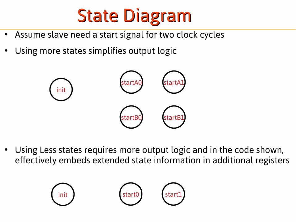
State DiagramState Diagram● Assume slave need a start signal for two clock cycles
● Using more states simplifies output logic
● Using Less states requires more output logic and in the code shown, effectively embeds extended state information in additional registers
startA0init
startA1
startB0 startB1
start0init start1

Registered Outputs With Single Always BlockRegistered Outputs With Single Always Blockmodule control_state_machine2( input clk, input rst, output reg startA, //start signal to slave A output reg startB, //start signal to slave B input busyA_n, //busy signal from slave A input busyB_n, //busy signal from slave B output ready, //ready signal to master input selAnB //go signal from master input start //go signal from master);
reg [7:0] CS;
localparam S_init = 8'b00000000;localparam S_start0 = 8'b00000001;localparam S_start1 = 8'b00000010;
assign ready = ~(selAnB?busyB_n:busyA_n);
always @ (posedge clk) begin if (rst == 1) CS<=S_init; else case (CS) S_init: begin if (start == 1) begin startA <= ~selAnB; startB <= selAnB; CS<=S_start0; end else begin startA <= 0; startB <= 0; CS<=S_init; end end S_start0: begin startA <= startA; startB <= startB; CS<=S_start1; end S_start1: begin startA <= 0; startB <= 0; CS<=S_init; end endcaseendendmodule
Coding update alongside transitionwithin the case code for the current state(the state held in the state register prior to the corresponding updates in the case code)
Timing DiagramTiming Diagram● Place holder for in-class timing diagram.
Key concepts:– Identification of implied combinatorial signals
including register inputs (outputs and state (NS))– Arrival of input changes versus response timing– Coincidence of Code and Output Timing

Registered Outputs 3-Always-Block StyleRegistered Outputs 3-Always-Block Style always @ (*) begin NS = CS; case (CS)
S_init: begin if (go) begin NS = S_start0; endendS_start0: NS = S_start1;S_start1: NS = S_init;
endcase // case (CS) end // always @ (*) always @ (posedge clk) begin case (NS)
S_init: startA <= 0; startB <= 0;S_start0: startA <= ~selAnB; startB <= selAnB;S_start1: startA <= startA; startB <= startB;
endcase end
endmodule
module control_state_machine2( input clk, input rst, output reg startA, //start signal to slave A output reg startB, //start signal to slave B input busyA_n, //busy signal from slave A input busyB_n, //busy signal from slave B output ready, //ready signal to master input selAnB //go signal from master input start //go signal from master);
reg [7:0] CS,NS;
localparam S_init = 8'b00000000;localparam S_start0 = 8'b00000001;localparam S_start1 = 8'b00000010;
assign ready = ~(selAnB?busyB_n:busyA_n);
always @ (posedge clk) begin if (rst == 1) CS<=S_init; else CS<=NS;end
*need to considerappropriate resets
and defaults logic as well