Embed Size (px)
Citation preview

Verification Examples
2008

AxisVM 9 Verification Examples 2
Linear static .............................................................................................................3 Supported bar with concentrated loads. .......................................................................................................................4 Thermally loaded bar structure.....................................................................................................................................5 Continously supported beam with constant distributed load.........................................................................................6 External prestessed beam...........................................................................................................................................9 Periodically supported infinite membrane wall with constant distributed load. ...........................................................11 Clamped beam examination with plane stress elements............................................................................................13 Clamped thin square plate..........................................................................................................................................16 Plate with fixed support and constant distributed load................................................................................................18 Annular plate. .............................................................................................................................................................19 All edges simply supported plate with partial distributed load. ...................................................................................21 Clamped plate with linear distributed load. .................................................................................................................23 Hemisphere displacement. .........................................................................................................................................25
Nonlinear static......................................................................................................27 3D beam structure. .....................................................................................................................................................28 Plate with fixed end and bending moment..................................................................................................................30
Dynamic.................................................................................................................33 Deep simply supported beam.....................................................................................................................................34 Clamped thin rhombic plate........................................................................................................................................37 Cantilevered thin square plate....................................................................................................................................39 Cantilevered tapered membrane. ...............................................................................................................................42 Flat grillages. ..............................................................................................................................................................45
Stability ..................................................................................................................49 Simply supported beam..............................................................................................................................................50 Simply supported beam..............................................................................................................................................52
Design ...................................................................................................................53 N-M interaction curve of cross-section (EN 1992-1-1:2004).......................................................................................54 RC beam deflection according to EC2, EN 1992-1-1:2004. .......................................................................................55 Required steel reinforcement of RC plate according to EC2, EN 1992-1-1:2004.......................................................57 Earth-quake design using response-spectrum method. .............................................................................................59
AxisVM 9 Verification Examples 3
Linear static

AxisVM 9 Verification Examples 4 Software Release Number: R2 Date: 12. 03. 2008. Tested by: InterCAD Page number: File name: beam1.axs Thema
Supported bar with concentrated loads.
Analysis Type
Linear analysis.
Geometry
Side view
Section Area = 1,0 m2
Loads
Axial direction forces P1 = -200 N, P2 = 100 N, P3 = -40 N
Boundary Conditions
Fix ends, at R1 and R5.
Material Properties
E = 20000 kN / cm2 ν = 0,3
Element types
Beam element
Mesh
Target
R1 , R5 support forces
Results
Theory AxisVM %
R1 [N] 118,00 118,00 0,00
R5 [N] 22,00 22,00 0,00

AxisVM 9 Verification Examples 5 Software Release Number: R2 Date: 12. 03. 2008. Tested by: InterCAD Page number: File name: beam2.axs Thema
Thermally loaded bar structure.
Analysis Type
Linear analysis.
Geometry
Side view Sections: Steel: AS = π x 10-4 m2
Copper: AC = π x 10-4 m2
Loads
P = -12 kN (Point load) Temperature rise of 10 °C in the structure after assembly.
Boundary Conditions
The upper end of bars are fixed.
Material Properties
Steel: ES = 20700 kN / cm2 , ν = 0,3 , αS = 1,2 x 10⁻⁵ °C-1
Copper: EC = 11040 kN / cm2 , ν = 0,3 , αC = 1,7 x 10⁻⁵ °C-1
Element types
Beam element
Target
Smax in the three bars.
Results
Theory AxisVM %
Steel Smax [MPa] 23824000 23848000 0,10
Cooper Smax [MPa] 7185300 7198900 0,19

AxisVM 9 Verification Examples 6 Software Release Number: R2 Date: 12. 03. 2008. Tested by: InterCAD Page number: File name: beam3.axs Thema
Continously supported beam with point loads.
Analysis Type
Linear analysis.
Geometry
Side view
(Section width = 1,00 m, height1 = 0,30 m, height2 = 0,60 m)
Loads
P1= -300 kN, P2= -1250 kN, P3= -800 kN, P4= -450 kN
Boundary Conditions
Elastic supported. From A to D is Kz = 25000 kN/m/m. From D to F is Kz = 15000 kN/m/m.
Material Properties
E = 3000 kN/cm2 ν = 0,3
Element types
Three node beam element. Shear deformation is taken into account.
Target ez, My, Vz, Rz Results Results
Diagram ez
Diagram My

AxisVM 9 Verification Examples 7
Diagram Vz
Diagram R
Reference AxisVM e [%]
eA [m] 0,006 0,006 0,00
eB [m] 0,009 0,009 0,00
eC [m] 0,014 0,014 0,00
eD [m] 0,015 0,015 0,00
eE [m] 0,015 0,015 0,00
eF [m] 0,013 0,013 0,00
Reference AxisVM e [%]
MA [KNm] 0,0 0,0 0,00
MB [KNm] 88,5 87,5 -1,13
MC [KNm] 636,2 632,8 -0,53
MD [KNm] 332,8 329,7 -0,93
ME [KNm] 164,2 163,3 -0,55
MF [KNm] 0,0 0,0 0,00
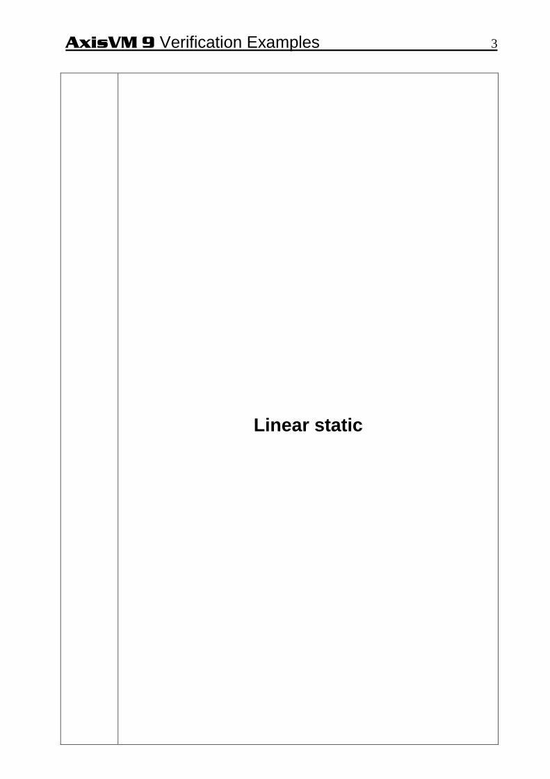
AxisVM 9 Verification Examples 8 Results
Reference AxisVM e [%]
VA [KN] 0,0 0,0 0,00
VB [KN] 112,1 113,1 0,89
VC [KN] 646,8 647,2 0,06
VD [KN] 335,0 334,9 -0,03
VE [KN] 267,8 267,5 -0,11
VF [KN] 0,0 0,0 0,00
Reference AxisVM e [%]
RA [KN/m2] 145,7 154,0 5,70
RB [KN/m2] 219,5 219,4 -0,05
RC [KN/m2] 343,8 346,0 0,64
RD [KN/m2] 386,9 386,4 -0,13
RE [KN/m2] 224,5 224,7 0,09
RF [KN/m2] 201,2 200,8 -0,20

AxisVM 9 Verification Examples 9 Software Release Number: R2 Date: 12. 03. 2008. Tested by: InterCAD Page number: File name: beam4.axs Thema
External prestessed beam.
Analysis Type
Linear analysis.
Geometry
Side view
Loads
p = -50 kN /m distributed load Length change = -6,52E-3 at beam 5-6
Boundary Conditions
eY = eZ = = 0 at node 1 eX = eY = eZ = 0 at node 4
Material Properties
E = 2,1E11 N / m2 Beam 1-5, 5-6, 6-4 A = 4,5E-3 m2 Iz= 0,2E-5 m4 Truss 2-5, 3-6 A = 3,48E-3 m2 Iz= 0,2E-5 m4 Beam 1-4 A = 1,1516E-2 m2 Iz= 2,174E-4 m4
Mesh
Element types
Three node beam element, 1-5, 5-6, 6-4, 1-4 (shear deformation is taken into account) Truss element 2-5, 3-6
Target
NX at beam 6-7 My,max at beam 2-3 ez at node 2

AxisVM 9 Verification Examples 10 Results
1 2 3 4
5 6
2,000 4,000 2,000
8,000
0,60
0
X
Z
Diagram ez
ROBOT V6® AxisVM %
Nx [kN] 584,56 585,70 0,19
My [kNm] 49,26 49,60 0,68
ez [mm] -0,5421 -0,5469 0,89

AxisVM 9 Verification Examples 11 Software Release Number: R2 Date: 12. 03. 2008. Tested by: InterCAD Page number: File name: plane1.axs Thema
Periodically supported infinite membrane wall with constant distributed load.
Analysis Type
Linear analysis.
Geometry
Side view
(thickness = 20,0 cm)
Loads
p = 200 kN / m
Boundary Conditions
vertical support at every 4,0 m support length is 0,4 m
Material Properties
E = 880 kN / cm2 ν = 0,16
Element types
Parabolic quadrilateral membrane (plane stress)
Mesh
Target
Sxx at 1-10 nodes (1-5 at middle, 6-10 at support)

AxisVM 9 Verification Examples 12 Results
Node Analytical [kN/cm 2] AxisVM [kN/cm 2] %
1 0,1313 0,1310 -0,232 0,0399 0,0395 -1,003 -0,0093 -0,0095 2,154 -0,0412 -0,0410 -0,495 -0,1073 -0,1070 -0,286 -0,9317 -0,9270 -0,507 0,0401 0,0426 6,238 0,0465 0,0469 0,869 0,0538 0,0540 0,37
10 0,1249 0,1240 -0,72 Reference: Dr. Bölcskey Elemér – Dr. Orosz Árpád: Vasbeton szerkezetek Faltartók, Lemezek, Tárolók

AxisVM 9 Verification Examples 13 Software Release Number: R2 Date: 12. 03. 2008. Tested by: InterCAD Page number: File name: plane2.axs Thema
Clamped beam examination with plane stress elements.
Analysis Type
Linear analysis.
Geometry
Side view
Loads
p = -25 kN/m
Boundary Conditions
Both ends built-in.
Material Properties
E = 880 kN / cm2 ν = 0
Element types
Parabolic quadrilateral membrane (plane stress)
Mesh
C
Clamped edge
1
3,000 0,250
0,50
0
0,375
C
Clamped edge
X
Z
Side view

AxisVM 9 Verification Examples 14 Target τxy, max at section C Results
Diagram τxy
5,28
791,56
5,14
5,28
791,56
5,14
5,28
791,56
5,14
5,28
791,56
5,14
Y
Z
Diagram τxy at section C

AxisVM 9 Verification Examples 15
2'
4
3'
/5,78700260416,025,0
0078125,0625,65
00260416,0
25,0
0078125,0
)(625,65
mkNIb
SV
mI
mb
mS
theorybeamfromkNV
y
yxy
y
y
=⋅
⋅=⋅⋅
=
=
=
=
=
τ
AxisVM result xyτ = 791,6 kN / m2
Difference = +0,52 %
AxisVM result kNnV xy 34,65==∑
Difference = +0,43 %
AxisVM 9 Verification Examples 16 Software Release Number: R2 Date: 12. 03. 2008. Tested by: InterCAD Page number: File name: plate1.axs Thema
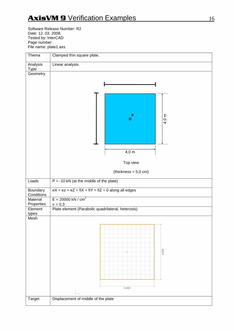
Clamped thin square plate.
Analysis Type
Linear analysis.
Geometry
Top view
(thickness = 5,0 cm)
Loads
P = -10 kN (at the middle of the plate)
Boundary Conditions
eX = ez = eZ = fiX = fiY = fiZ = 0 along all edges
Material Properties
E = 20000 kN / cm2 ν = 0,3
Element types
Plate element (Parabolic quadrilateral, heterosis)
Mesh
4,000
4,00
0
X
Y
Target
Displacement of middle of the plate

AxisVM 9 Verification Examples 17 Results
-0,001
-0,006
-0,012
-0,019
-0,024
-0,026
-0,026
-0,024
-0,019
-0,012
-0,006
-0,001
-0,006
-0,022
-0,043
-0,065
-0,081
-0,087
-0,087
-0,081
-0,065
-0,043
-0,022
-0,006
-0,012
-0,043
-0,084
-0,125
-0,156
-0,168
-0,168
-0,156
-0,125
-0,084
-0,043
-0,012
-0,019
-0,065
-0,125-0,187
-0,237
-0,257
-0,257
-0,237
-0,187
-0,125
-0,065
-0,019
-0,024
-0,081-0,156
-0,237-0,307
-0,337
-0,337
-0,307
-0,237
-0,156
-0,081
-0,024
-0,026
-0,087-0,168
-0,257-0,337
-0,383
-0,383
-0,337
-0,257
-0,168
-0,087
-0,026
-0,026
-0,087-0,168
-0,257-0,337
-0,383
-0,383
-0,337
-0,257
-0,168
-0,087
-0,026
-0,024
-0,081-0,156
-0,237-0,307
-0,337
-0,337
-0,307
-0,237
-0,156
-0,081
-0,024
-0,019
-0,065
-0,125-0,187
-0,237
-0,257
-0,257
-0,237
-0,187
-0,125
-0,065
-0,019
-0,012
-0,043
-0,084
-0,125
-0,156
-0,168
-0,168
-0,156
-0,125
-0,084
-0,043
-0,012
-0,006
-0,022
-0,043
-0,065
-0,081
-0,087
-0,087
-0,081
-0,065
-0,043
-0,022
-0,006
-0,001
-0,006
-0,012
-0,019
-0,024
-0,026
-0,026
-0,024
-0,019
-0,012
-0,006
-0,001
XY
Z
Displacements
Mode Mesh Book 1 Timoshenko 2 AxisVM Diff 1 [%] Diff 2 [%]1 2x2 0,402 0,420 4,48 10,532 4x4 0,416 0,369 -11,30 -2,893 8x8 0,394 0,381 -3,30 0,264 12x12 0,387 0,383 -1,03 0,795 16x16 0,385 0,383 -0,52 0,79
0,38
References: 1.) The Finite Element Method (Fourth Edition) Volume 2.
/O.C. Zienkiewicz and R.L. Taylor/ McGraw-Hill Book Company 1991 London 2.) Result of analytical solution of Timoshenko
Convergency
-15,00
-10,00
-5,00
0,00
5,00
10,00
15,00
1 2 3 4 5
Mesh density
Dis
plac
emen
ts
Diff1 [%]
Diff2 [%]

AxisVM 9 Verification Examples 18 Software Release Number: R2 Date: 12. 03. 2008. Tested by: InterCAD Page number: File name: plate2_1.axs Thema
Plate with fixed support and constant distributed load.
Analysis Type
Linear analysis.
Geometry
Top view
(thickness = 15,0 cm) Loads P = -5 kN / m2 Boundary Conditions
eX = eY = eZ = fiX = fiY = fiZ = 0 along all edges
Material Properties
E = 990 kN/cm2 ν = 0,16
Element types
Parabolic triangle plate element
Mesh
Target Maximal eX (found at Node1) and maximal mx (found at Node2) Results
Component Nastran® AxisVM %eZ,max [mm] -1,613 -1,593 -1,24
mx,max [kNm/m] 3,060 3,059 -0,03

AxisVM 9 Verification Examples 19 Software Release Number: R2 Date: 12. 03. 2008. Tested by: InterCAD Page number: File name: plate3.axs Thema
Annular plate.
Analysis Type
Linear analysis.
Geometry
Top view
(thickness = 22,0 cm)
Loads
Edge load: Q = 100 kN / m
Distributed load: q = 100 kN / m2
Boundary Conditions
Material Properties
E = 880 kN / cm2 ν = 0,3
Element types
Plate element (parabolic quadrilateral, heterosis)

AxisVM 9 Verification Examples 20 Mesh
4,000
1,0003,000
X
Y
Target Smax, emax
Results
Theory AxisVMModel Smax Smax %
[kN/cm2] [kN/cm2]a.) 2,82 2,78 -1,42b.) 6,88 6,76 -1,74c.) 14,22 14,10 -0,84d.) 1,33 1,33 0,00e.) 2,35 2,25 -4,26f.) 9,88 9,88 0,00g.) 4,79 4,76 -0,63h.) 7,86 7,86 0,00
Theory AxisVM
Model emax emax %[mm] [mm]
a.) 77,68 76,10 -2,03b.) 226,76 220,84 -2,61c.) 355,17 352,89 -0,64d.) 23,28 23,42 0,60e.) 44,26 44,50 0,54f.) 123,19 123,17 -0,02g.) 112,14 111,94 -0,18h.) 126,83 126,81 -0,02
Reference: S. Timoshenko and S. Woinowsky-Krieger: Theory of Plates And Shells

AxisVM 9 Verification Examples 21 Software Release Number: R2 Date: 12. 03. 2008. Tested by: InterCAD Page number: File name: plate4.axs Thema
All edges simply supported plate with partial distributed load.
Analysis Type
Linear analysis.
Geometry
Top view
(thickness = 22,0 cm)
Loads
Distributed load: q = -10 kN / m2 (middle of the plate at 2,0 x 2,0 m area)
Boundary Conditions
a.) eX = eY = eZ = 0 along all edges (soft support) b.) eX = eY = eZ = 0 along all edges ϕ = 0 perpendicular the edges (hard support)
Material Properties
E = 880 kN / cm2 ν = 0,3
Element types
Plate element (Heterosis)
Mesh
5,000
10,0
00
X
Y

AxisVM 9 Verification Examples 22 Target
mx, max, my, max
Results a.)
Moment Theory AxisVM %mx, max [kNm/m] 7,24 7,34 1,38my, max [kNm/m] 5,32 5,39 1,32
b.)
Moment Theory AxisVM %mx, max [kNm/m] 7,24 7,28 0,55my, max [kNm/m] 5,32 5,35 0,56
Reference: S. Timoshenko and S. Woinowsky-Krieger: Theory of Plates And Shells

AxisVM 9 Verification Examples 23 Software Release Number: R2 Date: 12. 03. 2008. Tested by: InterCAD Page number: File name: plate5.axs Thema
Clamped plate with linear distributed load.
Analysis Type
Linear analysis.
Geometry
Top view
(thickness = 22,0 cm)
Loads
Distributed load: q = -10 kN / m2
Boundary Conditions
eX = eY = eZ = fiX = fiY= fiZ = 0 along all edges
Material Properties
E = 880 kN / cm2 ν = 0,3
Element types
Plate element (Heterosis)
Mesh
1 23
4
q
10,000
10,
0001 23
4
q
X
Y
AxisVM 9 Verification Examples 24 Target
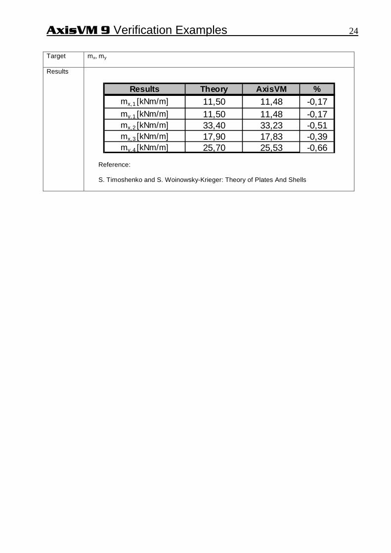
mx, my
Results
Results Theory AxisVM %mx,1 [kNm/m] 11,50 11,48 -0,17my,1 [kNm/m] 11,50 11,48 -0,17mx,2 [kNm/m] 33,40 33,23 -0,51mx,3 [kNm/m] 17,90 17,83 -0,39my,4 [kNm/m] 25,70 25,53 -0,66
Reference: S. Timoshenko and S. Woinowsky-Krieger: Theory of Plates And Shells

AxisVM 9 Verification Examples 25 Software Release Number: R2 Date: 12. 03. 2008. Tested by: InterCAD Page number: File name: hemisphere.axs Thema
Hemisphere displacement.
Analysis Type
Linear analysis.
Geometry
Hemisphere (Axonometric view)
t = 0,04 m
Loads
Point load P = 2,0 kN
2,0 kN 2,0 kN
AB
C
2,0 kN 2,0 kN
AB
C
X Y
Z

AxisVM 9 Verification Examples 26 Boundary Conditions
eX = eY = eZ = 0 at A eX = eY = eZ = 0 at B
Material Properties
E = 6825 kN / cm2 ν = 0,3
Element types
Shell element 1.) guadrilateral parabolic 2.) triangle parabolic
Target
ex at point A
Results
ex [m] e [%]
Theory 0,185
AxisVM quadrilateral 0,186 0,54
AxisVM triangle 0,185 0,00

AxisVM 9 Verification Examples 27
Nonlinear static

AxisVM 9 Verification Examples 28 Software Release Number: R2 Date: 12. 03. 2008. Tested by: InterCAD Page number: File name: nonlin1.axs Thema
3D beam structure.
Analysis Type
Geometrical nonlinear analysis.
Geometry
Fz=-600,00 kN
Fy=-300,00 kNFz=-600,00 kN
Fy=-300,00 kNFz=-600,00 kN
Node1
Beam1
A
B
C
D
Fz=-600,00 kN
Fy=-300,00 kNFz=-600,00 kN
Fy=-300,00 kNFz=-600,00 kN
Node1
Beam1
A
B
C
D
XY
Z
3,000 m1,7
32 m
1,732 m 1,732 m3,0
00 m
1,7
32 m
X
Y
4,0
00 m
X
Z
Loads
Py = -300 kN Pz = -600 kN
Boundary Conditions
eX = eY = eZ = 0 at A, B, C and D
Material Properties
S 275 E = 21000 kN / cm2 ν = 0,3
Cross- Section Properties
HEA 300 Ax = 112.56 cm2 ; Ix = 85.3 cm4 ; Iy = 18268.0 cm4 ; Iz = 6309.6 cm4
Element types
Beam
Target
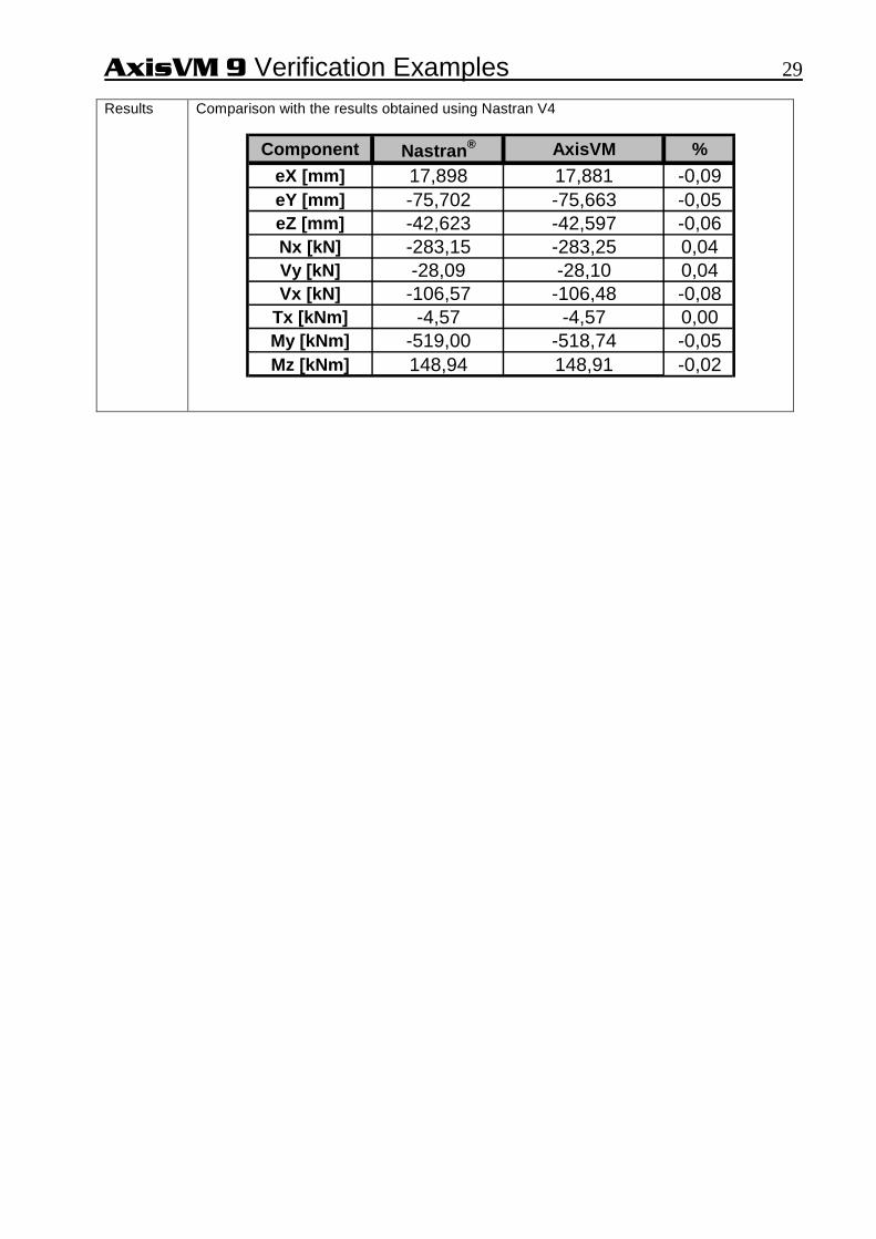
eX, eY, eZ, at Node1 Nx, Vy, Vz, Tx, My, Mz of Beam1 at Node1
AxisVM 9 Verification Examples 29 Results
Comparison with the results obtained using Nastran V4
Component Nastran ® AxisVM %
eX [mm] 17,898 17,881 -0,09eY [mm] -75,702 -75,663 -0,05eZ [mm] -42,623 -42,597 -0,06Nx [kN] -283,15 -283,25 0,04Vy [kN] -28,09 -28,10 0,04Vx [kN] -106,57 -106,48 -0,08
Tx [kNm] -4,57 -4,57 0,00My [kNm] -519,00 -518,74 -0,05Mz [kNm] 148,94 148,91 -0,02

AxisVM 9 Verification Examples 30 Software Release Number: R2 Date: 12. 03. 2008. Tested by: InterCAD Page number: File name: nonlin2.axs Thema
Plate with fixed end and bending moment.
Analysis Type
Geometrical nonlinear analysis.
Geometry
Edge1
Edge2
12,0 m
Edge1
Edge2
1,0 m
X
YZ
Loads Mz = 2600 kNm (2x1300 Nm) acting on Edge2 Boundary Conditions
eX = eY = eZ = fiX = fiY = fiZ = 0 along Edge1
Material Properties
E = 20000 N / mm2 ν = 0
Cross Section Properties
Plate thickness: 150 mm Rib on Edge2: circular D = 500 mm (for distributing load to the mid-side-node)
Element types
Parabolic quadrilateral shell (heterosis) Rib on Edge2 for distributing load to the mid-side-node

AxisVM 9 Verification Examples 31 Target ϕZ at Edge2 Results
Edge1
Edge2
5,5502 rad
12,0 m
Edge1
Edge2
5,5502 rad1,0 m
X
YZ
Theoretical results based on the differential equation of the flexible beam:
rad
NmM
m
mNE
baI
EI
MEI
M
z
plate
plate
plate
plateplate
platez
platez
plateplate
5467.5102108125.2
12106.2
106.2
12
102
108125.212
15.0112
104
6
6
210
433
=⋅⋅⋅
⋅⋅=
⋅=
=
⋅=
⋅=⋅==
=→
⋅=
=
−
−
ϕ
ϕκϕ
κ
l
l
l
Comparison the AxisVM result with the theoretical one:
Component Theory AxisVM %fiZ [rad] 5,5467 5,5502 0,06

AxisVM 9 Verification Examples 32
BLANK

AxisVM 9 Verification Examples 33
Dynamic

AxisVM 9 Verification Examples 34 Software Release Number: R2 Date: 12. 03. 2008. Tested by: InterCAD Page number: File name: dynam1.axs Thema
Deep simply supported beam.
Analysis Type
Dynamic analysis.
Geometry
Beam (Axonometric view)
Cross section (square 2,0 m x 2,0 m)
Loads
Self-weight
Boundary Conditions
eX = eY = eZ = fiX = 0 at A eY = eZ = 0 at B
Material Properties
E = 20000 kN / cm2 ν = 0,3 ρ = 8000 kg / m3
Element types
Three node beam element (shear deformation is taken into account)
Target
First 7 mode shapes

AxisVM 9 Verification Examples 35 Results
Mode 1: f = 43,16 Hz
Mode 3: f = 124,01 Hz
Mode 5: f = 152,50 Hz
Mode 7: f = 293,55 Hz
Mode 2: f = 43,16 Hz
Mode 4: f = 152,50 Hz
Mode 6: f = 293,55 Hz

AxisVM 9 Verification Examples 36 Results
Comparison with NAFEMS example
Mode NAFEMS (Hz) AxisVM (Hz) %1 42,65 43,16 -1,202 42,65 43,16 -1,203 125,00 124,01 0,794 148,31 152,50 -2,835 148,31 152,50 -2,836 284,55 293,55 -3,167 284,55 293,55 -3,16

AxisVM 9 Verification Examples 37 Software Release Number: R2 Date: 12. 03. 2008. Tested by: InterCAD Page number: File name: dynam2.axs Thema
Clamped thin rhombic plate.
Analysis Type
Dynamic analysis.
Geometry
Top view of plane
(thickness = 5,0 cm)
Loads
Self-weight
Boundary Conditions
eX = eY = fiZ = 0 at all nodes (ie: eX, eY, fiZ constained at all nodes) eZ = fiX = fiY = 0 along the 4 edges
Material Properties
E = 20000 kN / cm2 ν = 0,3 ρ = 8000 kg / m3
Element types
Parabolic quadrilateral shell element (heterosis)
Mesh
10,000
10,0
00
X
Y

AxisVM 9 Verification Examples 38 Target
First 6 mode shapes
Results eR
0,506
0,470
0,433
0,397
0,361
0,325
0,289
0,253
0,217
0,181
0,144
0,108
0,072
0,036
0
Mode 1: f = 8,02 Hz eR
0,486
0,451
0,416
0,382
0,347
0,312
0,278
0,243
0,208
0,174
0,139
0,104
0,069
0,035
0
Mode 3: f = 18,41 Hz eR
0,498
0,462
0,427
0,391
0,356
0,320
0,284
0,249
0,213
0,178
0,142
0,107
0,071
0,036
0
Mode 5: f = 24,62 Hz
eR
0,463
0,429
0,396
0,363
0,330
0,297
0,264
0,231
0,198
0,165
0,132
0,099
0,066
0,033
0
Mode 2: f = 13,02 Hz eR
0,520
0,483
0,446
0,409
0,372
0,335
0,297
0,260
0,223
0,186
0,149
0,112
0,074
0,037
0
Mode 4: f = 19,33 Hz eR
0,449
0,417
0,385
0,353
0,321
0,289
0,257
0,225
0,192
0,160
0,128
0,096
0,064
0,032
0
Mode 6: f = 28,24 Hz
Results
Comparison with NAFEMS example
Mode NAFEMS (Hz) AxisVM (Hz) %1 7,94 8,02 1,012 12,84 13,02 1,403 17,94 18,41 2,624 19,13 19,33 1,055 24,01 24,62 2,546 27,92 28,24 1,15

AxisVM 9 Verification Examples 39 Software Release Number: R2 Date: 12. 03. 2008. Tested by: InterCAD Page number: File name: dynam3.axs Thema
Cantilevered thin square plate.
Analysis Type
Dynamic analysis.
Geometry
Top view (thickness = 5,0 cm)
Loads
Self-weight
Boundary Conditions
eX = eY = eZ = fiX = fiY = fiZ = 0 along y-axis
Material Properties
E = 20000 kN / cm2 ν = 0,3 ρ = 8000 kg / m3
Element types
Parabolic quadrilateral shell element (heterosis).
Mesh

AxisVM 9 Verification Examples 40 Target
First 5 mode shapes
Results
Mode 1: f = 0,42 Hz
Mode 3: f = 2,53 Hz
Mode 5: f = 3,68 Hz

AxisVM 9 Verification Examples 41
Mode 2: f = 1,02 Hz
Mode 4: f = 3,22 Hz
Comparison with NAFEMS example
Mode NAFEMS (Hz) AxisVM (Hz) %1 0,421 0,420 -0,242 1,029 1,020 -0,873 2,580 2,530 -1,944 3,310 3,220 -2,725 3,750 3,680 -1,87

AxisVM 9 Verification Examples 42 Software Release Number: R2 Date: 12. 03. 2008. Tested by: InterCAD Page number: File name: dynam4.axs Thema
Cantilevered tapered membrane.
Analysis Type
Dynamic analysis.
Geometry
Side view
(thickness = 10,0 cm)
Loads
Self-weight
Boundary Conditions
eZ = 0 at all nodes (ie: eZ constained at all nodes) eX = eY = 0 along y-axis
Material Properties
E = 20000 kN / cm2 ν = 0,3 ρ = 8000 kg / m3
Element types
Parabolic quadrilateral membrane (plane stress)
Mesh
10,000
1,00
0
5,00
0
X
Y

AxisVM 9 Verification Examples 43 Target
First 4 mode shapes
Results
Mode 1: f = 44,33 Hz
10,000
1,00
0
5,00
0
X
Y
Mode 2: f = 128,36 Hz
10,000
1,000 5,000
X Y

AxisVM 9 Verification Examples 44
10,000
1,00
0
5,00
0
X
Y
Mode 3: f = 162,48 Hz
10,000
1,00
0
5,00
0
X
Y
Mode 4: f = 241,22 Hz
Results
Comparison with NAFEMS example
Mode NAFEMS (Hz) AxisVM (Hz) %1 44,62 44,33 -0,652 130,03 128,36 -1,283 162,70 162,48 -0,144 246,05 241,22 -1,96

AxisVM 9 Verification Examples 45 Software Release Number: R2 Date: 12. 03. 2008. Tested by: InterCAD Page number: File name: dynam5.axs Thema
Flat grillages.
Analysis Type
Dynamic analysis.
Geometry
Top view
Loads
Self-weight
Boundary Conditions
eX = eY = eZ = 0 at the ends (simple supported beams)
Material Properties
E = 20000 kN / cm2 G = 7690 kN / cm2 ν = 0,3 ρ = 7860 kg / m3
Cross Section
A = 0,004 m2 Ix = 2,5E-5 m4 Iy = Iz = 1,25E-5 m4
Element types
Three node beam element (shear deformation is taken into account)
Mesh
1,500 1,500 1,500
1,00
02,
000
0,5001,000 4,500
1,000 0,500
X
Y
AxisVM 9 Verification Examples 46 Target
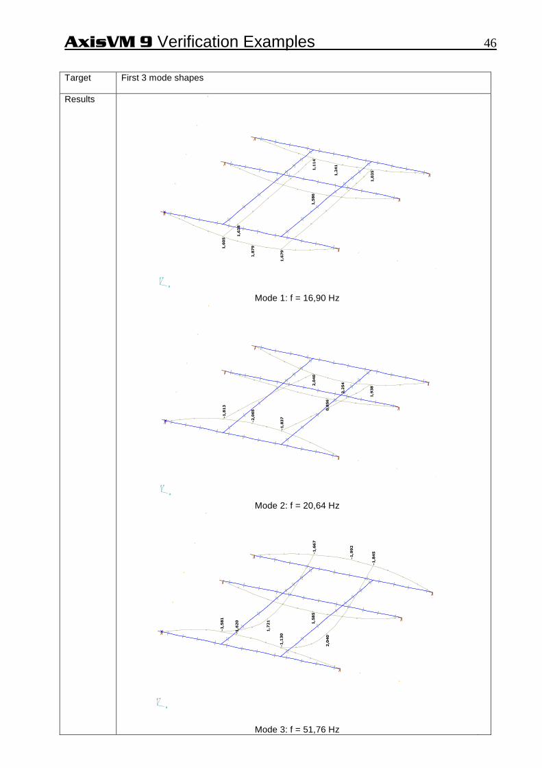
First 3 mode shapes
Results
1,8
79
1,5
86
1,2
41
1,1
14
1,6
05
1,6
38
1,0
35
1,6
79
X
YZ
Mode 1: f = 16,90 Hz
-2,0
65 0
,856
2,2
542,0
40
-1,8
13
1,9
38
-1,8
37
X
YZ
Mode 2: f = 20,64 Hz
-1,6
20 1,5
85
-1,9
92
-1,6
67
-1,5
81
1,7
21
-1,8
45
-1,1
30
2,0
40
X
YZ
Mode 3: f = 51,76 Hz
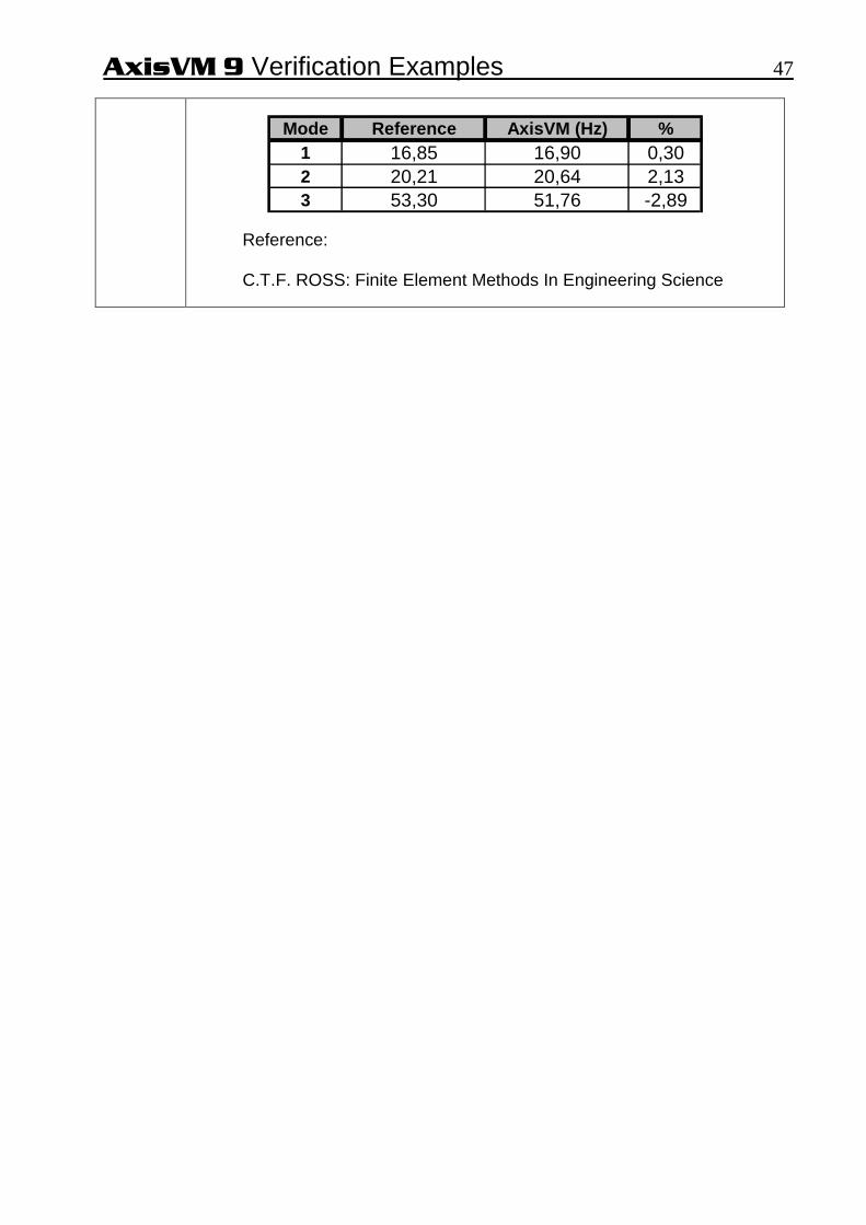
AxisVM 9 Verification Examples 47
Mode Reference AxisVM (Hz) %1 16,85 16,90 0,302 20,21 20,64 2,133 53,30 51,76 -2,89
Reference: C.T.F. ROSS: Finite Element Methods In Engineering Science

AxisVM 9 Verification Examples 48
BLANK

AxisVM 9 Verification Examples 49
Stability
AxisVM 9 Verification Examples 50 Software Release Number: R2 Date: 12. 03. 2008. Tested by: InterCAD Page number: File name: buckling1.axs Thema
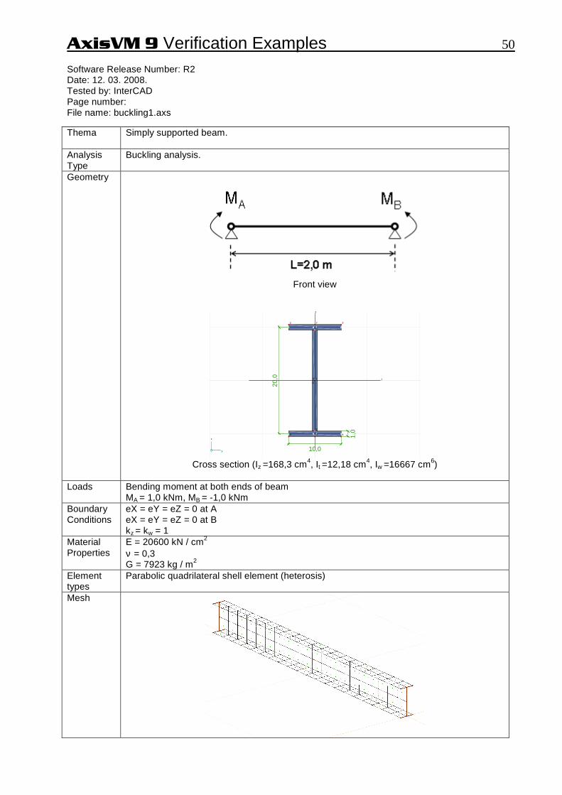
Simply supported beam.
Analysis Type
Buckling analysis.
Geometry
Front view
1
2 3
45
6
7
8
9
S
G
1
2
10,0
1,0
20,0
y
z
Cross section (Iz =168,3 cm4, It =12,18 cm4, Iw =16667 cm6)
Loads
Bending moment at both ends of beam MA = 1,0 kNm, MB = -1,0 kNm
Boundary Conditions
eX = eY = eZ = 0 at A eX = eY = eZ = 0 at B kz = kw = 1
Material Properties
E = 20600 kN / cm2 ν = 0,3 G = 7923 kg / m2
Element types
Parabolic quadrilateral shell element (heterosis)
Mesh

AxisVM 9 Verification Examples 51 Target
Mcr = ? (for lateral torsional buckling)
Results
Analytical solution
Z
t
Z
WZcr IE
IGL
I
I
L
IEM
⋅⋅⋅⋅+⋅⋅= 2
2
2
2
ππ
kNmkNcmM cr 51,124124513,16820600
18,1279232003,168
16667200
3,168206002
2
2
2
==⋅⋅⋅⋅+⋅⋅=
ππ
AxisVM result Mcr = 125,3 kNm Difference +0,6%

AxisVM 9 Verification Examples 52 Software Release Number: R2 Date: 12. 03. 2008. Tested by: InterCAD Page number: File name: buckling2.axs Thema
Simply supported beam.
Analysis Type
Buckling analysis.
Geometry
Front view (L = 1,0 m)
1
2
3 4
5
S
G
1
2
12,0
10,0
y
z
1
2
3 4
5
S
G
2
30,0
10,
0
y
z
Section A1 Section A2 Cross-sections
Loads
P = -1,0 N at point B.
Boundary Conditions
eX = eY = eZ = 0 at A eY = eZ = 0 at B
Material Properties
E = 20000 kN / cm2 ν = 0,3
Element types
Beam element
Target
Pcr = ? (for inplane buckling)
Results
Theory AxisVM e [%]
Pcr [N] 3340,0 3337,0 -0,09

AxisVM 9 Verification Examples 53
Design

AxisVM 9 Verification Examples 54 Software Release Number: R2 Date: 12. 03. 2008. Tested by: InterCAD Page number: File name: RC column1.axs Thema
N-M interaction curve of cross-section (EN 1992-1-1:2004).
Analysis Type
Linear static analysis+design.
Geometry
2φ20 3φ28 Section: 300x400 mm Covering: 40 mm
Loads
Boundary Conditions
Material Properties
Concrete: fcd=14,2 N/mm2 ec1=0,0007 ecu=0,0035 (rectangular σ-ε diagram) Steel: fsd=348 N/mm2 esu=0,015
Target
Compare the program results with with hand calculation at keypoints of M-N interaction curve.
Results
N 1 2 6
5 3
4 Reference: Dr. Kollár L. P., Vasbetonszerkezetek I. Műegyetemi kiadó
N [kN] M [kNm] M(N) AxisVM e% 1 -2561 +61 +61,4 +0,7 2 -1221 +211 +212,3 +0,6 3 0 +70 +70,5 +0,7 4 +861 -61 -61,4 +0,7 5 0 -190 -191,2 +0,6 6 -362 +211 +212,3 +0,6

AxisVM 9 Verification Examples 55 Software Release Number: R2 Date: 12. 03. 2008. Tested by: InterCAD Page number: File name: beam1.axs Thema
RC beam deflection according to EC2, EN 1992-1-1:2004.
Analysis Type
Material nonlinear analysis.
Geometry
q = 17 kN/m L = 5,60 m
Side view
2φ20 35 cm covering = 3 cm β = 0,5 4φ20
25 cm
Section
Loads
q = 17 kN /m distributed load
Boundary Conditions
Simply supported beam.
Material Properties
Concrete: C25/30, ϕ = 2,1 Steel: B500B
Element types
Parabolic quadrilateral plate element (Heterosis)
Target
ez, max

AxisVM 9 Verification Examples 56 Results
-0,0
02-0
,002
-0,0
02-0
,002
-5,2
39-5
,239
-10,
101
-10,
101
-14,
242
-14,
242
-17,
393
-17,
393
-19,
360
-19,
360
-20,
029
-20,
029
-19,
360
-19,
360
-17,
393
-17,
393
-14,
242
-14,
242
-10,
101
-10,
101
-5,2
39-5
,239
-5,2
39-5
,239
-10,
101
-10,
101
-14,
242
-14,
242
-17,
393
-17,
393
-19,
360
-19,
360
-20,
029
-20,
029
-20,
029
-20,
029
-19,
360
-19,
360
-17,
393
-17,
393
-14,
242
-14,
242
-10,
101
-10,
101
-5,2
39-5
,239
-5,2
39-5
,239
-10,
101
-10,
101
-14,
242
-14,
242
-17,
393
-17,
393
-19,
360
-19,
360
-20,
029
-20,
029
-20,
029
-20,
029
-19,
360
-19,
360
-17,
393
-17,
393
-14,
242
-14,
242
-10,
101
-10,
101
-5,2
39-5
,239
X
Z
Diagram ez
Aproximate calculation:
mmeee III _06,20)1( =⋅−+⋅= ζζ where, eI is the deflection which was calculated with the uncracked inertia moment eII is the deflection which was calculated with the cracked inertia moment
2
1
⋅−=
s
sr
σσβζ
Calculation with integral of κ: e = 19,82 mm Calculation with AxisVM: e = 20,03 mm (different +1,1%)

AxisVM 9 Verification Examples 57 Software Release Number: R2 Date: 12. 03. 2008. Tested by: InterCAD Page number: File name: beam2.axs Thema
Required steel reinforcement of RC plate according to EC2, EN 1992-1-1:2004.
Analysis Type
Linear analysis.
Geometry
50 kN50 kN
4,0
X
Y
Szabvány : Eurocode
Eset : ST1
Side view
Cross-section
Loads
Pz = -50 kN point load
Boundary Conditions
Clamped cantilever plate.
Material Properties
Concrete: C25/30 Steel: B500A
Element types
Parabolic quadrilateral plate element (heterosis)
Mesh
Clamped edge
4,0
1,0
Clamped edge
X
Y
Szabvány : Eurocode
Eset : ST1
Top view

AxisVM 9 Verification Examples 58 Target
AXT steel reinforcement along x direction at the top of the support
Results
Clamped edge ST1, axf: 2093 mm2/m
4,0
1,0
Clamped edge ST1, axf: 2093 mm2/m
XY
Z
Lineáris számítás
Szabvány : Eurocode
Eset : ST1
E (W) : 1,09E-11
E (P) : 1,09E-11
E (ER) : 8,49E-13
Komp. : axf [mm2 /m]
Diagram AXT
Calculation according to EC2:
2/6,165,1
25mmNfcd == 2/435
15,1500
mmNf yd ==
54,0435200000035,0
200000035,085,00 =
+⋅⋅⋅=
+⋅⋅⋅=
ydScu
Scuc fE
Ec
εεξ
d = 300 – 53 = 247 mm
kNmx
dfxbMM ccdcRdsd 200
2=
−⋅⋅==
>
=55
439 hxc
54,022,024755
0 =<=== cc
c d
x ξξ Steel reinforcement is yielding
22099435
6,16100055mm
f
fxbA
yd
cdcS =⋅⋅=⋅⋅=
Calculation with AxisVM:
AXT = mmm /2093 2 Different = -0,3 %
AxisVM 9 Verification Examples 59 Software Release Number: R2 Date: 12. 03. 2008. Tested by: InterCAD Page number: File name: Earthquake-01-EC.axs Thema
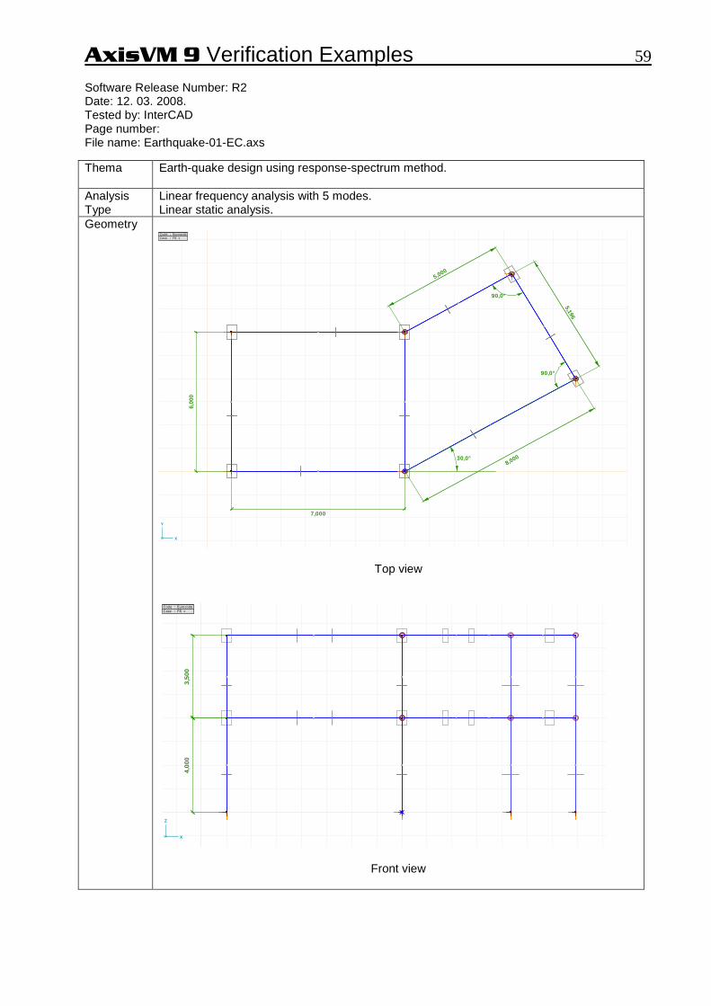
Earth-quake design using response-spectrum method.
Analysis Type
Linear frequency analysis with 5 modes. Linear static analysis.
Geometry
6,00
0
7,000
8,00030,0°
5,196
5,000
90,0°
90,0°
X
Y
Code : Eurocode
Case : FR +
Top view
4,00
03,
500
X
Z
Code : Eurocode
Case : FR +
Front view

AxisVM 9 Verification Examples 60
All columns 60x40 cm
All nodal masses are Mx=My=Mz=100000 kg
Column A
Column B
All beams 60x40 cmInertia about vertical axis is multiplied by 1000.
All supports are constrained in all directions.eX=eY=eZ=fiX=fiY=fiZ=0
Support C
Node D
All columns 60x40 cm
All nodal masses are Mx=My=Mz=100000 kg
Column A
Column B
All beams 60x40 cmInertia about vertical axis is multiplied by 1000.
All supports are constrained in all directions.eX=eY=eZ=fiX=fiY=fiZ=0
Support C
Node D
XY
Z
Code : Eurocode
Case : ST1
Perspective view
Section beams: 60x40 cm
Ax=2400 cm2 Ay=2000 cm2 Az=2000 cm2 Ix=751200 cm4 Iy=720000 cm2 Iz=320000000 cm4
Section columns: 60x40 cm
Ax=2400 cm2 Ay=2000 cm2 Az=2000 cm2 Ix=751200 cm4 Iy=720000 cm2 Iz=320000 cm4
Loads
Nodal masses on eight nodes. Mx=My=Mz=100000 kg Model self-weight is excluded. Spectrum for X and Y direction of seismic action:
Sd [m/s2 ]
T[s]
1,150
2,156
0,300
2,0000
0,709
T[s] Sd
1 0 1,150
2 0,2000 2,156
3 0,6000 2,156
4 1,3000 0,995
5 3,0000 0,300
6 4,0000 0,300
. . . . . .
Boundary Conditions
Nodes at the columns bottom ends are constrained in all directions. eX=eY=eZ=fiX=fiY=fiZ=0
Material Properties
C25/30 E=3050 kN/cm2 ν =0,2 ρ = 0

AxisVM 9 Verification Examples 61 Element types
Three node straight prismatic beam element. Shear deformation is taken into account.
Target
Compare the model results with SAP2000 v6.13 results. The results are combined for all modes and all direction of spectral acceleration. CQC combination are used for modes in each direction of acceleration. SRSS combination are used for combination of directions.
Results
Period times of first 5 modes Mode T[s] SAP2000 T[s] AxisVM Difference [%]
1 0,7450 0,7450 0 2 0,7099 0,7099 0 3 0,3601 0,3601 0 4 0,2314 0,2314 0 5 0,2054 0,2054 0
Modal participating mass ratios in X and Y directions
Mode εX SAP2000
εX AxisVM
Difference %
εY SAP2000
εY AxisVM
Difference %
1 0,5719 0,5719 0 0,3153 0,3154 +0,03 2 0,3650 0,3650 0 0,4761 0,4760 -0,02 3 0 0 0 0,1261 0,1261 0 4 0,0460 0,0460 0 0,0131 0,0131 0 5 0,0170 0,0170 0 0,0562 0,0562 0
Summ 1,0000 1,0000 0 0,9868 0,9868 0 Internal forces at the bottom end of Column A and Column B
Column A SAP2000
Column A AxisVM
Difference %
Column B SAP2000
Column B AxisVM
Difference %
Nx [kN] 315,11 315,15 +0,01 557,26 557,29 +0,005 Vy [kN] 280,34 280,34 0 232,88 232,88 0 Vz [kN] 253,49 253,49 0 412,04 412,04 0
Tx [kNm] 34,42 34,41 -0,03 34,47 34,46 -0,03 My [kNm] 625,13 625,12 -0,002 1038,74 1038,70 -0,004 Mz [kNm] 612,31 612,31 0 553,41 553,41 0
Support forces of Support C
Support C SAP2000
Support C AxisVM
Difference %
Rx [kN] 280,34 280,34 0 Ry [kN] 253,49 253,49 0 Rz [kN] 315,11 315,15 +0,01
Rxx [kNm] 625,13 625,12 -0,002 Ryy [kNm] 612,31 612,31 0 Rzz [kNm] 34,42 34,41 -0,03
Displacements of Node D
Node D SAP2000
Node D AxisVM
Difference %
eX [mm] 33,521 33,521 0 eY [mm] 19,944 19,945 +0,005 eZ [mm] 0,229 0,229 0 ϕX [rad] 0,00133 0,00133 0 ϕY [rad] 0,00106 0,00106 0 ϕZ [rad] 0,00257 0,00257 0

AxisVM 9 Verification Examples 62 Normal forces:

AxisVM 9 Verification Examples 63 Bending moments:

AxisVM 9 Verification Examples 64

AxisVM 9 Verification Examples 65 Displacements:

![Design Patterns by Example for SystemVerilog Verification ... · PDF fileSystemVerilog Verification Environments Enabled by ... pattern examples: the Strategy Pattern [4] [5 ... Example](https://img.dokumen.tips/doc/110x75/5ab319097f8b9aea528df471/design-patterns-by-example-for-systemverilog-verification-verification-environments.jpg)