Embed Size (px)
Citation preview
11th European LS-DYNA Conference 2017, Salzburg, Austria
© 2017 Copyright by DYNAmore GmbH
Verification and Validation of LS-DYNA® for the Transport and Storage of Radioactive Materials
Gilles Marchaud1, Valérie Saint-Jean1
1AREVA TN, Montigny-le-Bretonneux, France
1 Introduction For 50 years, AREVA TN has been supplying customer-focused, innovative transportation and storage solutions for radioactive material with the highest levels of safety and security. Transportation and storage casks are designed to comply with stringent regulations. For instance, a cask designed to transport radioactive material may be required to withstand a 9m drop onto a flat unyielding target. AREVA TN performs LS-DYNA analyses to evaluate the crashworthiness of casks and to reduce the number of costly real tests. Such a methodology relies on the capability of the computer code to model the main physical phenomena that occur in a cask and its content when they are subject to a transient mechanical event. The validity of LS-DYNA is confirmed by comparing its results with reference results, for a variety of test cases covering these phenomena. The reference results are obtained either analytically or from real tests. AREVA TN defined specific test cases to validate aspects such as constitutive laws, rigid-body displacement, geometric nonlinearities or contacts. The present paper will focus on a selection of these test cases and present their features as well as their results.
2 Transport and Storage Regulations and Numerical Analyses The international regulations for transport [1] are issued by the International Atomic Energy Agency (IAEA), a United Nations agency. The IAEA regulations define standard scenarios that have been designed to be representative of the real events a loaded cask may be subject to and shall withstand so that the hazards to persons and the environment remain under an acceptable level of control. Section VII of [1] specifies the standard drop tests a given cask should be able to withstand. The beginning of section VII explains that the safety demonstration can be based on a combination of real tests, reasoned arguments and calculations: “Section VII – TEST PROCEDURES
DEMONSTRATION OF COMPLIANCE
701. Demonstration of compliance with the performance standards required in Section VI shall be accomplished by any of the following methods or by a combination thereof:
(a) Performance of tests (…) with prototypes or samples of the packaging (…). (b) Reference to previous satisfactory demonstrations of a sufficiently similar nature. (c) Performance of tests with models of appropriate scale, (…). (d) Calculation, or reasoned argument, when the calculation procedures and parameters are generally agreed to be reliable or conservative.” Thus, the regulations emphasize the requirement for reliable or conservative calculations. Another IAEA document [2] brings guidance for applying IAEA regulations [1]. Regarding paragraph 701 of [1], document [2] explains the following:
11th European LS-DYNA Conference 2017, Salzburg, Austria
© 2017 Copyright by DYNAmore GmbH
“701.13. Many calculations could require the use of commercially available computer codes. The reliability and the appropriate validation of the computer code selected should be considered. First, is the code applicable for the intended calculation? For example, for mechanical assessments, can it accept impact calculations? Is it suitable for calculating plastic as well as elastic deformations? Second, does the computer code adequately represent the packaging under review for the purpose of compliance? To meet these two criteria, it may be necessary for the user to run ‘benchmark’ problems, which use the code to model and calculate the parameters of a problem in which the results are known. Options settings may have a strong influence on the validity of the benchmark studies to the problem being solved. In mechanical codes, options and modelling considerations include package material properties under dynamic conditions, elastic and plastic deformations, detailing connections between components such as screws and welds, and allowing for friction, hydrodynamic, sliding and damping effects. User experience in the proper selection of code options, material properties and mesh selection can affect results using a particular code. Benchmark studies should also consider sensitivity of the results to parameter variation. Confidence can be increased by systematic benchmarking, proceeding from the simple to the complex. For other uses, checks that the input and output balances in load or energy may be required. When the code used is not widely employed or known, proof of the theoretical correctness should also be given.” The calculations may be carried out with computer codes and may replace some real tests. The use of a widely employed commercial computer code such as LS-DYNA [3] avoids having to prove the main theories behind the code. LS-DYNA is obviously capable of modeling the main physical phenomena that occur in a cask and its content when they are subject to a transient mechanical event. However, LS-DYNA has to be used with the appropriate options settings, the appropriate element formulations, the appropriate material laws and parameters, etc. Moreover, LS-DYNA indicators of good convergence (such as hourglass energy) also have to be checked.
3 AREVA TN’s Current Practice to Guarantee the Validity of Numerical Analyses In order to meet these conditions, AREVA TN uses the following methodology: “Qualification” of a given version of LS-DYNA
The validity of LS-DYNA is confirmed by comparing its results with reference results, for a variety of test cases covering the main phenomena at stake. The reference results are obtained either analytically or from real tests.
“Validation” of a given computer system for a given version of LS-DYNA
The validity of LS-DYNA, when run on the given computer system (hardware, OS) with a given number of cores used in SMP, is confirmed by comparing its results with the results obtained during the qualification process. Remark: for repeatability reasons and accuracy reasons, only SMP, double-precision versions of LS-DYNA are used.
Benchmarking of real tests LS-DYNA models of entire casks are usually benchmarked against real tests to validate them before being used for sensitivity analyses.
Checking of analyses Every LS-DYNA analysis is thoroughly checked with the help of a dedicated checklist. In addition to the model check itself, it also includes a check of the qualification field.
Capitalization of know-how An internal “standard” is updated to record good practice and feedback that shall be taken into account in all calculations performed.
Staff skills Diplomas, attendance to training courses and experience are recorded in an individual skill follow-up document.
Table 1: AREVA TN’s methodology to guarantee the validity of numerical analyses.
11th European LS-DYNA Conference 2017, Salzburg, Austria
© 2017 Copyright by DYNAmore GmbH
It should be noted that “Qualification” and “Validation” as defined above (“Q&V” for short herein) do not correspond directly to the classical definitions of “Verification” and “Validation” (“V&V”, see [10]), but the set of Q&V actions and the set of V&V actions almost coincide.
4 Qualification of LS-DYNA The validity of a given version of LS-DYNA is confirmed by comparing its results with reference results, for a variety of test cases covering the main phenomena at stake. The reference results are obtained either analytically or from real tests. AREVA TN has defined specific test cases to validate: - The main constitutive laws suitable for shock absorbing materials (for example woods) and metals, - The time integration scheme, with a view to the conservation of total energy, - The implementation of geometric nonlinearities (large displacements and rotations), - The correct representation of mass/stiffness distribution (vibrations, rigid-body displacements), - Shockwave propagation, - Energy dissipation in a complex structure composed with components in contact with each other. Test cases no. 1, 2, 4 and 9 will be presented in the present paper:
Type of test case ID Test case What is tested Element
types Materials Reference results
Simple
1 Free vibration of a simply-supported
beam
- Time integration scheme - Conservation of energy - Mass and stiffness matrices
Solid, Shell Elastic Analytical
[4]
2 Pendulum
- Time integration scheme - Conservation of energy - Mass distribution - Geometric non-linearities
(large displ. and rotations)
Solid, Shell Elastic Analytical
[5], [6]
Inter- mediate 3 Pipe with internal
pressure - Elastic-plastic behavior - Quasi-static analysis Solid Elastic-plastic Analytical
Complex
4 Bar impact (Taylor test)
- High-speed dynamics - Plastic impact - Shockwave propagation
Solid Elastic-plastic Impact
test [7]
5 M42 screw preload - Quasi-static equilibrium Solid Elastic Analytical
6 Axial crushing of a
pre-deformed tube - Benchmark
- Elastic-plastic behavior - Large strains - Elastic-plastic buckling
Solid
Elastic-plastic, with strain-rate
dependency
Crushing test
7 Confined crushing of wood cylinders with inclined fibers
- Wood behavior Solid Wood Analytical
8
Low-velocity impact onto a concrete
structure – Benchmark
- Concrete behavior - Coupling with rebars
Solid, beam
Elastic-plastic (steel),
concrete
Impact test
9 Oblique drop of TN®17/2 cask –
Benchmark
- Impact of a complex structure
Solid, Shell
Elastic-plastic (steel), wood
Drop test [9]
Table 2: Description of the qualification test cases. Non-grayed cases will be presented.
LS-DYNA results have been obtained with LS-DYNA version R6.1.1 SMP double precision.

11th European LS-DYNA Conference 2017, Salzburg, Austria
© 2017 Copyright by DYNAmore GmbH
4.1 Test Case 1: Free Vibration of a Simply-Supported Beam
4.1.1 Description
An elastic beam, with both ends simply supported, is initially undeformed. An initial transverse velocity field is defined and represents the first eigenmode of the beam: the transverse velocity is a sine function of the abscissa along the beam (half a period). We are interested in conservation of energy and in the eigenperiod. Capturing vibrations properly is important to accurately assess dynamic amplification phenomena that might occur in impacted casks.
4.1.2 Geometry
The beam is a parallelepiped: length L = 1 m, width b = 100 mm, thickness h = 50 mm. Ratio h/L = 1/20 makes it possible to apply the theory of thin shells: shear strains can be neglected with respect to bending strains.
4.1.3 Material
Material Density ρ [kg/m3] Young’s modulus E [GPa] Poisson’s ratio ν
Linear elastic steel 7850 210 0.3
4.1.4 Initial Conditions
Y-component of velocity is: ( )LxvxvY /cos)( 0 π×= with =0v 1 m/s.
Beam ends are located at abscissas: 2/Lx ±= . The velocity is low enough so that the maximum displacement corresponds to a “membrane” internal energy (“taut string” effect) that is negligible with respect to the bending internal energy.
4.1.5 Boundary Conditions
The 3 translational degrees of freedom are fixed for all nodes located simultaneously on the mid-thickness plane and at one beam end.
4.1.6 Reference Results
Angular frequency of first eigenmode of beam: 4..LmIEk=ω [4]
Where: 98=k Coefficient depending on boundary conditions 12/. 3hbI = Moment of inertia of the beam cross-section
hbm ..ρ= Mass per unit length.
The eigenperiod can be calculated as follows: IELm
kT
..12
4
π= = 8.501834 ms
4.1.7 LS-DYNA Models
More or less fine meshes are tested, with either solid or shell elements (see Fig. 1).

11th European LS-DYNA Conference 2017, Salzburg, Austria
© 2017 Copyright by DYNAmore GmbH
Fig.1: Meshes for the beam vibration test case.
Several element formulations are tested:
Element formulation
Nodes per element
DDL per node
Integration points Per element On mid-
surface Through the
thickness Solid 1:
Constant stress (default) 8 3 1 - -
Solid 2: Fully integrated S/R 8 3 8 - -
Shell 2: Belytschko-Tsay 4 6 2 1 2
Shell 6: S/R Hughes-Liu 4 6 8 (a)
2 (b) 4 (a) 1 (b) 2
(a) For membrane and bending strains. (b) For out-of-plane shear strains.
Table 3: Element formulations for the beam vibration test case.
Hourglass control type: default (standard LS-DYNA viscous form). Material: type 1 *MAT_ELASTIC (linear elastic isotropic). The time step is determined automatically (default).
4.1.8 LS-DYNA Results – Comparison with Reference Results
Conservation of energy is measured with the ratio: (kinetic energy + internal energy at t=10ms) / (kinetic energy + internal energy at t=0). The eigenperiod is measured as the second time when the mid-length y-displacement is zero.
11th European LS-DYNA Conference 2017, Salzburg, Austria
© 2017 Copyright by DYNAmore GmbH
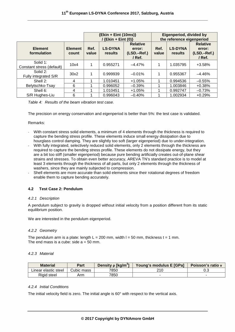
{Ekin + Eint (10ms)} / {Ekin + Eint (0)}
Eigenperiod, divided by the reference eigenperiod
Element formulation
Element count
Ref. value
LS-DYNA results
Relative error:
(LSD.–Ref.) / Ref.
Ref. value
LS-DYNA results
Relative error:
(LSD.–Ref.) / Ref.
Solid 1: Constant stress (default) 10x4 1 0.955271 –4.47% 1 1.035795 +3.58%
Solid 2: Fully integrated S/R 30x2 1 0.999939 –0.01% 1 0.955367 –4.46%
Shell 2: Belytschko-Tsay
4 1 1.010451 +1.05% 1 0.994536 –0.55% 6 1 0.996052 –0.39% 1 1.003846 +0.38%
Shell 6: S/R Hughes-Liu
4 1 1.010451 +1.05% 1 0.992747 –0.73% 6 1 0.996043 –0.40% 1 1.002934 +0.29%
Table 4: Results of the beam vibration test case.
The precision on energy conservation and eigenperiod is better than 5%: the test case is validated. Remarks: - With constant stress solid elements, a minimum of 4 elements through the thickness is required to
capture the bending stress profile. These elements induce small energy dissipation due to hourglass control damping. They are slightly too soft (larger eigenperiod) due to under-integration.
- With fully integrated, selectively reduced solid elements, only 2 elements through the thickness are required to capture the bending stress profile. These elements do not dissipate energy, but they are a bit too stiff (smaller eigenperiod) because pure bending artificially creates out-of-plane shear strains and stresses. To obtain even better accuracy, AREVA TN’s standard practice is to model at least 3 elements through the thickness of all parts, but only 2 elements through the thickness of washers, since they are mainly subjected to compression.
- Shell elements are more accurate than solid elements since their rotational degrees of freedom enable them to capture bending accurately.
4.2 Test Case 2: Pendulum
4.2.1 Description
A pendulum subject to gravity is dropped without initial velocity from a position different from its static equilibrium position. We are interested in the pendulum eigenperiod.
4.2.2 Geometry
The pendulum arm is a plate: length L = 200 mm, width l = 50 mm, thickness t = 1 mm. The end mass is a cube: side a = 50 mm.
4.2.3 Material
Material Part Density ρ [kg/m3] Young’s modulus E [GPa] Poisson’s ratio ν
Linear elastic steel Cubic mass 7850 210 0.3 Rigid steel Arm 7850 - -
4.2.4 Initial Conditions
The initial velocity field is zero. The initial angle is 60° with respect to the vertical axis.
11th European LS-DYNA Conference 2017, Salzburg, Austria
© 2017 Copyright by DYNAmore GmbH
4.2.5 Boundary Conditions
The 3 translational degrees of freedom are fixed for the pivotal node.
4.2.6 Load
A gravity field g = 9.81 m/s2 is applied in the –y direction.
4.2.7 Reference Results
For small oscillations, the eigenperiod is (formula m 56 of [5]): OG
O
lgmJT
..2π= = 0.9617667 s
Where: OJ mass moment of inertia w.r.t. pivotal point O m total mass of pendulum =g 9.81 m/s2 gravity acceleration
OGl distance between O and c.o.g. G.
With: cubeO
armOO JJJ += ( ) ( )
2222
2.4
12.
++=+=
LmLlmlmJJ armarm
OGarmarmarmGarm
armO
( ) ( )2
222
2.4
12.
+++=+=
aLmaamlmJJ cubecube
OGcubecubecubeGcube
cubeO
cubearm mmm += elLmarm ...ρ= 3.amcube ρ=
( ) ( )[ ] maLmLml cubearmOG /2/.2/. ++= For large oscillations, the eigenperiod depends on the initial angle ([6]):
81.'
20θ+=TT = 1.02551553 s
TT '
= 1.06633852
4.2.8 LS-DYNA Model
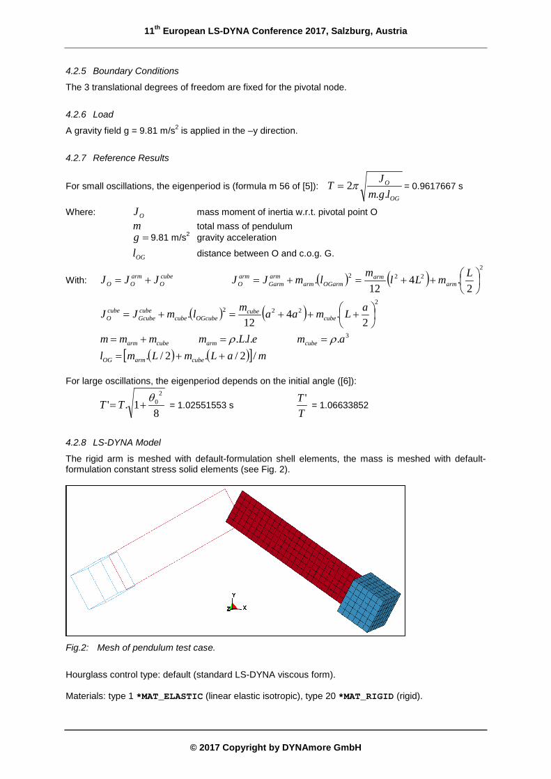
The rigid arm is meshed with default-formulation shell elements, the mass is meshed with default-formulation constant stress solid elements (see Fig. 2).
Fig.2: Mesh of pendulum test case.
Hourglass control type: default (standard LS-DYNA viscous form). Materials: type 1 *MAT_ELASTIC (linear elastic isotropic), type 20 *MAT_RIGID (rigid).
11th European LS-DYNA Conference 2017, Salzburg, Austria
© 2017 Copyright by DYNAmore GmbH
Gravity is applied thanks to *LOAD_BODY_Y. The time step is determined automatically (default).
4.2.9 LS-DYNA Results – Comparison with Reference Results
The half eigenperiod is measured as the time when vertical velocity vy of cube central node is zero again.
Half eigenperiod Ref. value LS-DYNA results Relative error:
(LS-DYNA – Ref.) / Ref. 0.512758 s 0.509254 s –0.68%
Table 5: Results of the pendulum test case.
LS-DYNA correctly captures geometric non-linearities due to large displacements and rotations: the test case is validated.
4.3 Test Case 4: Bar Impact (Taylor Test)
4.3.1 Description
An elastic-plastic cylindrical bar impacts a rigid planar target with a high velocity (120–266 m/s). The real test is described in ref. [7]. We are interested in: - The propagation velocity of an acoustic wave along the bar just after the impact begins, - The deformed geometry of the bar after the impact.
4.3.2 Geometry
Cylindrical bar: length L = 16 mm, radius R = 4 mm.
4.3.3 Material
Material Density ρ [kg/m3]
Young’s modulus E [GPa]
Poisson’s ratio ν
Quasi-static yield stress
)0(eσ [MPa] Elastic-plastic stainless steel 7850 210 0.3 340
On the plastic domain boundary, the Von Mises stress is a function of the equivalent plastic strain and of the equivalent plastic strain rate:
( )npep eβeσeeσ .1).(),( +=
The strain-rate dependency is described by a Cowper-Symonds law: p
ee C
/1
1).0()(
+=
eσeσ
The values of the coefficients are: β = 43, n = 0.35, C = 104 s-1, p = 3.
4.3.4 Initial Conditions, Boundary Conditions
The initial velocity is 120, 176 and 266 m/s. The bar/target contact is frictionless.
11th European LS-DYNA Conference 2017, Salzburg, Austria
© 2017 Copyright by DYNAmore GmbH
4.3.5 Reference Results
After the real tests, the deformed bar length was measured, as well as the radius of the forward, rear and mid-length cross-sections:
Impact velocity [m/s]
Length after impact [mm]
Forward radius [mm]
Mid-length radius [mm]
Rear radius [mm]
0 16 4 4 4 120 15.3 - - - 176 14.6 4.8 4.1 4.0 266 13.3 5.5 4.2 4.0
4.3.6 LS-DYNA Model
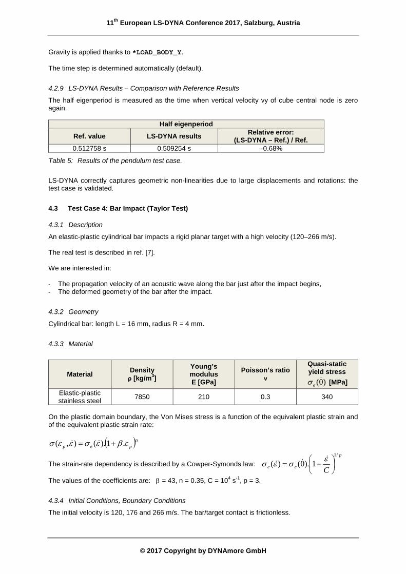
The bar is meshed with default-formulation constant stress solid elements (see Fig. 3), 32 along its length and 8 along the radius.
Fig.3: Mesh of Taylor test bar.
Hourglass control type: default (standard LS-DYNA viscous form). Material: type 24 *MAT_PIECEWISE_LINEAR_PLASTICITY (Cowper-Symonds law enabled). The appropriate boundary conditions are applied on the symmetry planes of the quarter model. The time step is determined automatically (default).
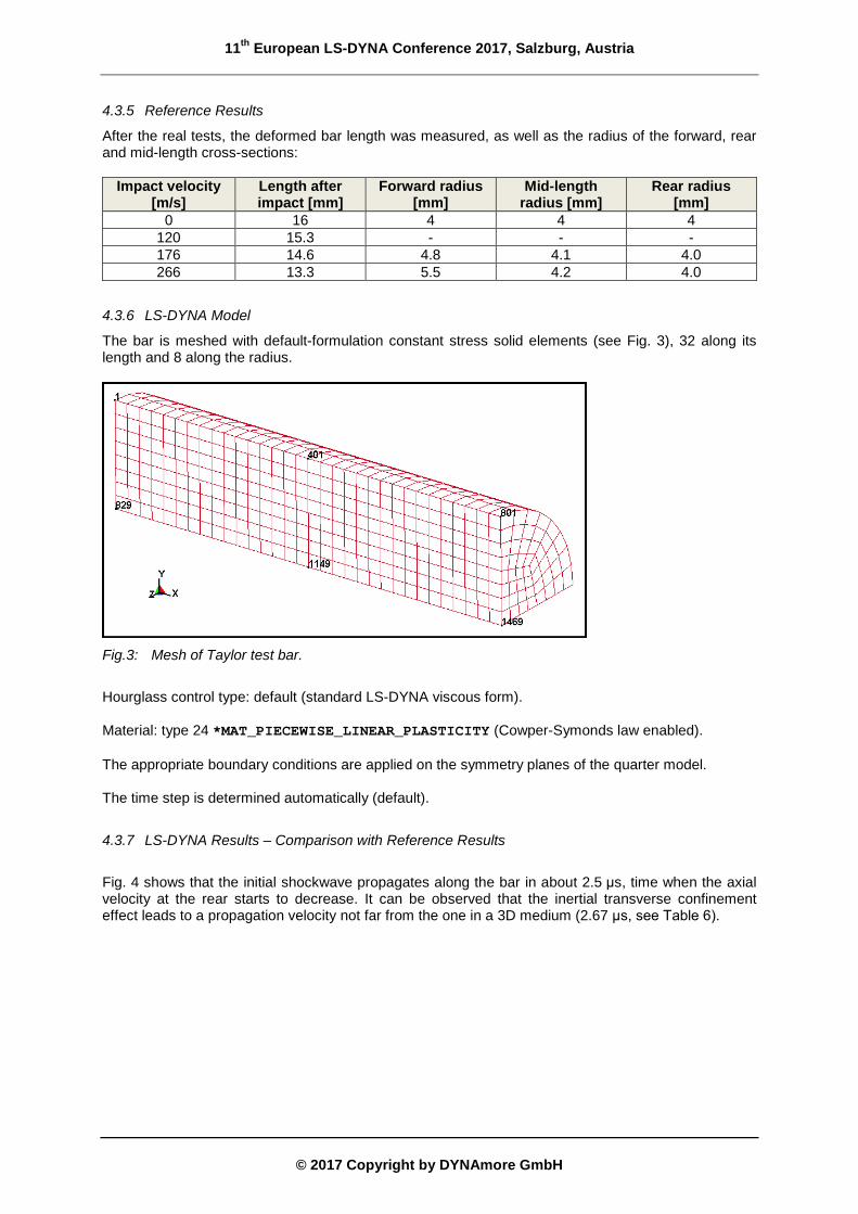
4.3.7 LS-DYNA Results – Comparison with Reference Results
Fig. 4 shows that the initial shockwave propagates along the bar in about 2.5 μs, time when the axial velocity at the rear starts to decrease. It can be observed that the inertial transverse confinement effect leads to a propagation velocity not far from the one in a 3D medium (2.67 μs, see Table 6).
11th European LS-DYNA Conference 2017, Salzburg, Austria
© 2017 Copyright by DYNAmore GmbH
Fig.4: Impact velocity: 120 m/s. Axial velocity measured along the bar axis.
Medium Propagation velocity Propagation delay [μs] for a compressive elastic shockwave along the bar: t = L / c Formula Value [m/s]
1D ρEc D =1 5172 3.09
2D ( )22 1 νρ −=
Ec D 5422 2.95
3D ( )
( )( )ννρν
2111
3 −+−
=Ec D 6001 2.67
Table 6: Theoretical propagation delays along the bar.
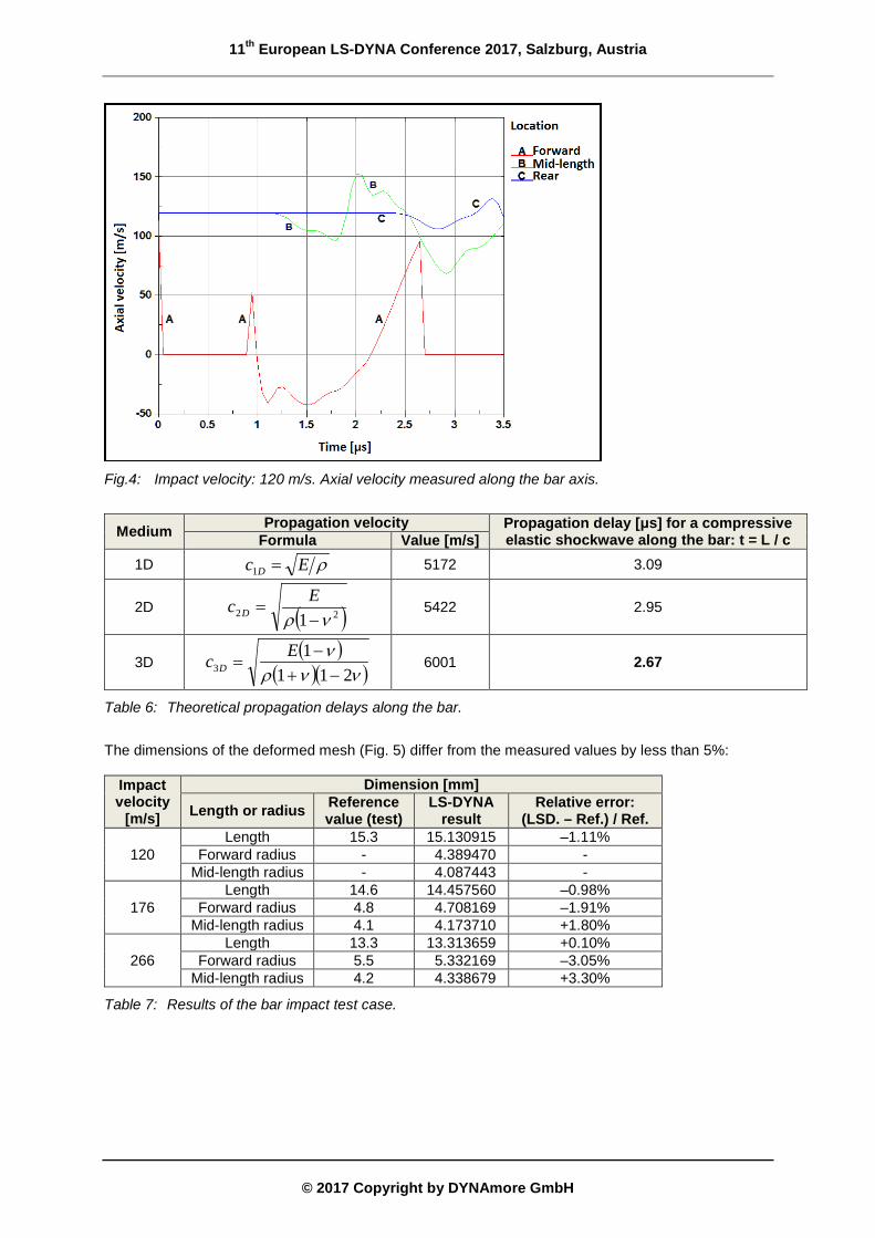
The dimensions of the deformed mesh (Fig. 5) differ from the measured values by less than 5%:
Impact velocity
[m/s]
Dimension [mm] Length or radius Reference
value (test) LS-DYNA
result Relative error:
(LSD. – Ref.) / Ref.
120 Length 15.3 15.130915 –1.11%
Forward radius - 4.389470 - Mid-length radius - 4.087443 -
176 Length 14.6 14.457560 –0.98%
Forward radius 4.8 4.708169 –1.91% Mid-length radius 4.1 4.173710 +1.80%
266 Length 13.3 13.313659 +0.10%
Forward radius 5.5 5.332169 –3.05% Mid-length radius 4.2 4.338679 +3.30%
Table 7: Results of the bar impact test case.
11th European LS-DYNA Conference 2017, Salzburg, Austria
© 2017 Copyright by DYNAmore GmbH
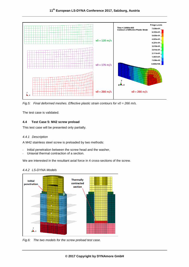
Fig.5: Final deformed meshes. Effective plastic strain contours for v0 = 266 m/s.
The test case is validated.
4.4 Test Case 5: M42 screw preload This test case will be presented only partially.
4.4.1 Description
A M42 stainless steel screw is preloaded by two methods: - Initial penetration between the screw head and the washer, - Uniaxial thermal contraction of a section. We are interested in the resultant axial force in 4 cross-sections of the screw.
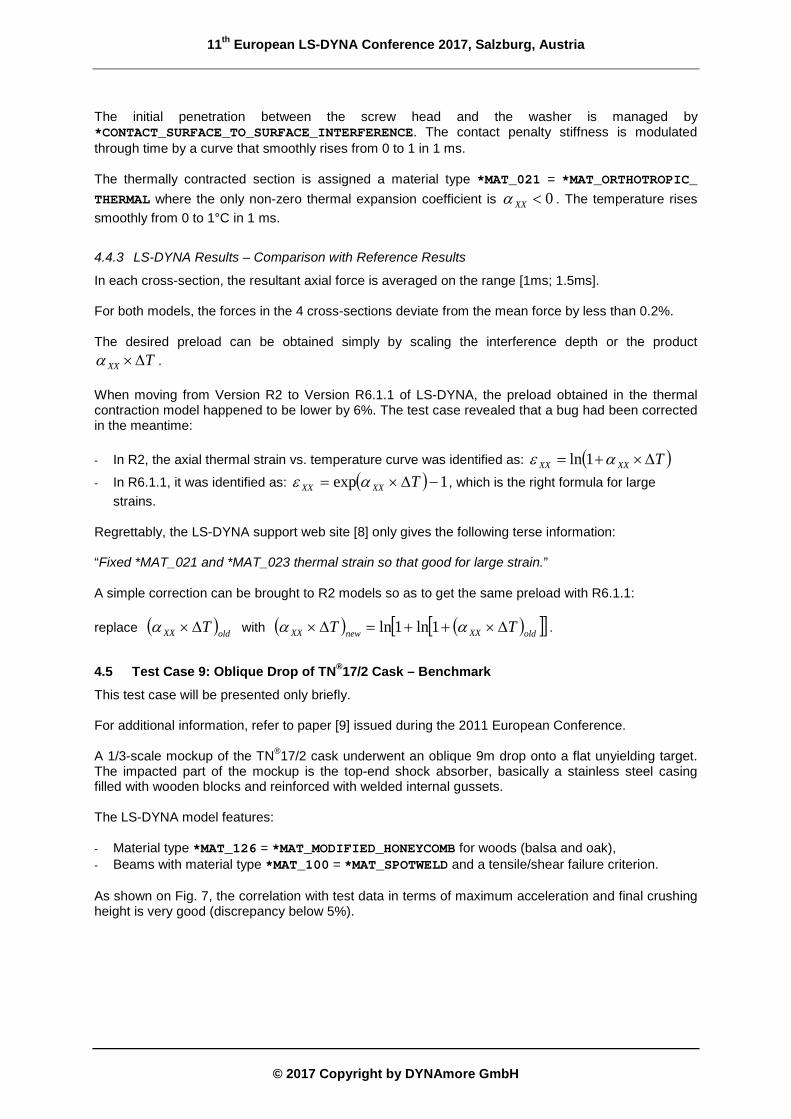
4.4.2 LS-DYNA Models
Fig.6: The two models for the screw preload test case.
11th European LS-DYNA Conference 2017, Salzburg, Austria
© 2017 Copyright by DYNAmore GmbH
The initial penetration between the screw head and the washer is managed by *CONTACT_SURFACE_TO_SURFACE_INTERFERENCE. The contact penalty stiffness is modulated through time by a curve that smoothly rises from 0 to 1 in 1 ms. The thermally contracted section is assigned a material type *MAT_021 = *MAT_ORTHOTROPIC_ THERMAL where the only non-zero thermal expansion coefficient is 0<XXα . The temperature rises smoothly from 0 to 1°C in 1 ms.
4.4.3 LS-DYNA Results – Comparison with Reference Results
In each cross-section, the resultant axial force is averaged on the range [1ms; 1.5ms]. For both models, the forces in the 4 cross-sections deviate from the mean force by less than 0.2%. The desired preload can be obtained simply by scaling the interference depth or the product
TXX ∆×α . When moving from Version R2 to Version R6.1.1 of LS-DYNA, the preload obtained in the thermal contraction model happened to be lower by 6%. The test case revealed that a bug had been corrected in the meantime: - In R2, the axial thermal strain vs. temperature curve was identified as: ( )TXXXX ∆×+= αe 1ln
- In R6.1.1, it was identified as: ( ) 1exp −∆×= TXXXX αe , which is the right formula for large strains.
Regrettably, the LS-DYNA support web site [8] only gives the following terse information: “Fixed *MAT_021 and *MAT_023 thermal strain so that good for large strain.” A simple correction can be brought to R2 models so as to get the same preload with R6.1.1: replace ( )oldXX T∆×α with ( ) ( )[ ][ ]oldXXnewXX TT ∆×++=∆× αα 1ln1ln .
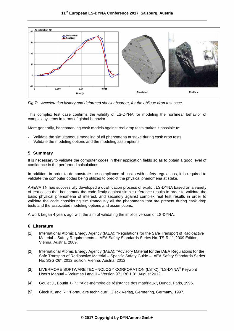
4.5 Test Case 9: Oblique Drop of TN®17/2 Cask – Benchmark This test case will be presented only briefly. For additional information, refer to paper [9] issued during the 2011 European Conference. A 1/3-scale mockup of the TN®17/2 cask underwent an oblique 9m drop onto a flat unyielding target. The impacted part of the mockup is the top-end shock absorber, basically a stainless steel casing filled with wooden blocks and reinforced with welded internal gussets. The LS-DYNA model features: - Material type *MAT_126 = *MAT_MODIFIED_HONEYCOMB for woods (balsa and oak), - Beams with material type *MAT_100 = *MAT_SPOTWELD and a tensile/shear failure criterion. As shown on Fig. 7, the correlation with test data in terms of maximum acceleration and final crushing height is very good (discrepancy below 5%).
11th European LS-DYNA Conference 2017, Salzburg, Austria
© 2017 Copyright by DYNAmore GmbH
Fig.7: Acceleration history and deformed shock absorber, for the oblique drop test case.
This complex test case confirms the validity of LS-DYNA for modeling the nonlinear behavior of complex systems in terms of global behavior. More generally, benchmarking cask models against real drop tests makes it possible to: - Validate the simultaneous modeling of all phenomena at stake during cask drop tests, - Validate the modeling options and the modeling assumptions.
5 Summary It is necessary to validate the computer codes in their application fields so as to obtain a good level of confidence in the performed calculations. In addition, in order to demonstrate the compliance of casks with safety regulations, it is required to validate the computer codes being utilized to predict the physical phenomena at stake. AREVA TN has successfully developed a qualification process of explicit LS-DYNA based on a variety of test cases that benchmark the code firstly against simple reference results in order to validate the basic physical phenomena of interest, and secondly against complex real test results in order to validate the code considering simultaneously all the phenomena that are present during cask drop tests and the associated modeling options and assumptions. A work began 4 years ago with the aim of validating the implicit version of LS-DYNA.
6 Literature [1] International Atomic Energy Agency (IAEA): “Regulations for the Safe Transport of Radioactive
Material – Safety Requirements – IAEA Safety Standards Series No. TS-R-1”, 2009 Edition, Vienna, Austria, 2009.
[2] International Atomic Energy Agency (IAEA): “Advisory Material for the IAEA Regulations for the
Safe Transport of Radioactive Material – Specific Safety Guide – IAEA Safety Standards Series No. SSG-26”, 2012 Edition, Vienna, Austria, 2012.
[3] LIVERMORE SOFTWARE TECHNOLOGY CORPORATION (LSTC): “LS-DYNA® Keyword
User's Manual – Volumes I and II – Version 971 R6.1.0”, August 2012. [4] Goulet J., Boutin J.-P.: “Aide-mémoire de résistance des matériaux”, Dunod, Paris, 1996. [5] Gieck K. and R.: “Formulaire technique”, Gieck Verlag, Germering, Germany, 1997.
11th European LS-DYNA Conference 2017, Salzburg, Austria
© 2017 Copyright by DYNAmore GmbH
[6] Pérez J.-Ph.: “Mécanique – Fondements et applications”, 6th Edition, Masson Sciences, Dunod, Paris, 2001.
[7] Calleja P., Terras C., Dormeval R., Ansart J.-P. (CEA): “Essai de Taylor sur de l’aluminium, du
cuivre et de l’acier inoxydable”, Journal de Physique, colloquium C5, supplement to no. 8, Vol. 46, August 1985, pp. C5-91 to C5-99.
[8] LS-DYNA Support Web Site, page “LS-DYNA V971 R3.1 (R3.43919) released”:
http://www.dynasupport.com/news/ls-dyna-v971-r3.1-r3.43919-released [Accessed 6 March 2017].
[9] Collin F.: “Simulation of shock absorbers behavior during a 9m drop test”, Proc. 8th Eur. LS-
DYNA Users Conf., Strasbourg, France, 2011. [10] Digital Engineering Web Site, page “Verification vs. Validation in Relation to FEA”:
http://www.digitaleng.news/de/verification-vs-validation/ [Accessed 7 March 2017].