Embed Size (px)
Citation preview

Save this manual for future reference.
OWNER’S OPERATION AND INSTALLATION MANUAL
VENT-FREE PROPANE/LP GASBAY FRONT FIREPLACE
®CF26PR19,000 to 26,000 Btu/HrRemote Control Ready
This appliance may be installed in an aftermarket* manufactured (mobile) home, where not prohibited by stateor local codes.
*Aftermarket: Completion of sale, not for purpose of resale, from the manufacturer. (I.E. Installation of this product is permi tted after themanufactured (mobile) home is sited)
WARNING: If the information in this manual is notfollowed exactly, a fire or explosion may result caus-ing property damage, personal injury, or loss of life.
— Do not store or use gasoline or other flammablevapors and liquids in the vicinity of this or anyother appliance.
— WHAT TO DO IF YOU SMELL GAS• Do not try to light any appliance.• Do not touch any electrical switch; do not
use any phone in your building.• Immediately call your gas supplier from a
neighbor’s phone. Follow the gas supplier’sinstructions.
• If you cannot reach your gas supplier, callthe fire department.
— Installation and service must be performed bya qualified installer, service agency, or the gassupplier.
WARNING: Improper installation,adjustment, alteration, service,or maintenance can cause injuryor property damage. Refer to thismanual for correct installationand operational procedures. Forassistance or additional infor-mation consult a qualified in-staller, service agency, or thegas supplier.
WARNING: This is an unventedgas-fired heater. It uses air (oxy-gen) from the room in which it isinstalled. Provisions for ad-equate combustion and ventila-tion air must be provided. Referto Air for Combustion and Ven-tilation section on page 4 of thismanual.
Patent Pending
Fireplace ShownWith Optional
Brass Accent TrimAUTOOFFON

2 105442
VENT-FREE PROPANE/LP BAY FRONT FIREPLACE CF26PR
1. This appliance is only for use with thetype of gas indicated on the rating plate.This appliance is not convertible for usewith other gases.
2. Do not place propane/LP supply tank(s)inside any structure. Locate propane/LP supply tank(s) outdoors.
DANGER: Carbon monoxidepoisoning may lead to death!
SAFETYINFORMATION
Carbon Monoxide Poisoning: Earlysigns of carbon monoxide poisoning re-semble the flu, with headaches, dizziness,or nausea. If you have these signs, the fire-place may not be working properly. Getfresh air at once! Have fireplace serviced.Some people are more affected by carbonmonoxide than others. These include preg-nant women, people with heart or lung dis-ease or anemia, those under the influence ofalcohol, and those at high altitudes.
Propane/LP Gas: Propane/LP gas is odor-less. An odor-making agent is added to pro-pane/LP gas. The odor helps you detect apropane/LP gas leak. However, the odor addedto propane/LP gas can fade. Propane/LP gasmay be present even though no odor exists.
Make certain you read and understand allWarnings. Keep this manual for reference.It is your guide to safe and proper operationof this fireplace.
WARNING ICON G 001 WARNINGS
IMPORTANT: Read this owner’smanual carefully and completelybefore trying to assemble, oper-ate, or service this fireplace. Im-proper use of this fireplace cancause serious injury or death fromburns, fire, explosion, electricalshock, and carbon monoxidepoisoning.
WARNING: Any change to thisfireplace or its controls can bedangerous.
3. If you smell gas• shut off gas supply• do not try to light any appliance• do not touch any electrical switch; do
not use any phone in your building• immediately call your gas supplier
from a neighbor’s phone. Follow thegas supplier’s instructions
• if you cannot reach your gas supplier,call the fire department
4. This fireplace shall not be installed ina bedroom or bathroom.
5. Never install the fireplace• in a recreational vehicle.• where curtains, furniture, clothing, or
other flammable objects are less than42 inches from the front, top, or sidesof the fireplace.
• as a fireplace insert.• in high traffic areas.• in windy or drafty areas.
6. Do not use this fireplace as a wood-burning fireplace. Use only the logsprovided with the fireplace.
7. Do not add extra logs or ornamentssuch as pine cones, vermiculite, or rockwool. Using these added items cancause sooting. Do not add lava rockaround base. Rock and debris could fallinto the control area of fireplace.
8. You must operate this fireplace with thefireplace screen in place. Make surefireplace screen is in place before run-ning fireplace.
9. This fireplace is designed to be smoke-less. If logs ever appear to smoke, turnoff fireplace and call a qualified ser-vice person. Note: During initial op-eration, slight smoking could occur dueto log curing and fireplace burningmanufacturing residues.
10. To prevent the creation of soot, followthe instructions in Cleaning and Main-tenance, page 19.
11. Do not allow fans to blow directly intothe fireplace. Avoid any drafts that al-ter burner flame patterns. Ceiling fanscan create drafts that alter burner flamepatterns. Altered burner patterns cancause sooting.
12. Before using furniture polish, wax, car-pet cleaner, or similar products, turnheater off. If heated, the vapors from
these products may create a white pow-der residue within burner box or onadjacent walls or furniture.
13. This fireplace needs fresh air ventila-tion to run properly. This fireplace hasan oxygen depletion sensor (ODS) pi-lot light safety system. The ODS shutsdown the fireplace if not enough freshair is available. See Air for Combus-tion and Ventilation, pages 4 through6. If fireplace keeps shutting off, seeTroubleshooting, pages 20 through 22.
14. Do not run fireplace• where flammable liquids or vapors
are used or stored.• under dusty conditions.
15. Do not use this fireplace to cook foodor burn paper or other objects.
16. Never place any objects in the fireplaceor on logs.
17. Fireplace front and screen becomesvery hot when running fireplace. Keepchildren and adults away from hot sur-faces to avoid burns or clothing igni-tion. Fireplace will remain hot for atime after shutdown. Allow surfaces tocool before touching.
18. Carefully supervise young children whenthey are in same room with fireplace.
19. Do not use fireplace if any part has beenunder water. Immediately call a quali-fied service technician to inspect theroom fireplace and to replace any partof the control system and any gas con-trol which has been under water.
20. Turn off and unplug fireplace and letcool before servicing. Only a qualifiedservice person should service and re-pair fireplace.
21. Operating fireplace above elevations of4,500 feet could cause pilot outage.
22. Do not use a blower insert, heat ex-changer insert, or other accessory notapproved for use with this fireplace.
23. Do not operate fireplace if any log isbroken. Do not operate fireplace if alog is chipped (dime-sized or larger).
24. To prevent performance problems, donot use propane/LP fuel tank of lessthan 100 lbs. capacity.

3105442
OWNER’S MANUAL
AUTOOFFON
PRODUCTIDENTIFICATION
LOCAL CODESInstall and use fireplace with care. Follow alllocal codes. In the absence of local codes, usethe latest edition of The National Fuel GasCode ANS Z223.1, also known as NFPA 54*.
*Available from:
American National Standards Institute, Inc.1430 Broadway
New York, NY 10018
National Fire Protection Association, Inc.Batterymarch ParkQuincy, MA 02269
Figure 1 - Vent-Free Propane/LP Gas Compact Fireplace
UNPACKING1. Remove and fireplace from carton.
2. Remove all protective packaging ap-plied to fireplace for shipment.
3. Make sure your fireplace includes onehardware packet.
4. Check fireplace for any shipping damage.If fireplace is damaged, promptly informdealer where you bought fireplace.
PRODUCTFEATURESSAFETY PILOTThis fireplace has a pilot with an OxygenDepletion Sensor Shutoff System (ODS).The ODS/pilot is a required feature for vent-free room fireplaces. The ODS/pilot shuts offthe fireplace if there is not enough fresh air.
PIEZO IGNITION SYSTEMThis fireplace has a piezo ignitor. This sys-tem requires no matches, batteries, or othersources to light fireplace.
Heater Controls(Inside Door)
Screen
FireplaceCabinet
Logs
REMOTE CONTROLACCESSORIESThere are four optional remote controls thatcan be purchased separately for this logheater:
• wall switch
• wall thermostat
• hand-held ON/OFF remote
• hand-held thermostat remote
See Accessories, page 28.
BrickLiner

4 105442
VENT-FREE PROPANE/LP BAY FRONT FIREPLACE CF26PR
Today’s homes are built more energy effi-cient than ever. New materials, increasedinsulation, and new construction methodshelp reduce heat loss in homes. Homeowners weather strip and caulk aroundwindows and doors to keep the cold air outand the warm air in. During heating months,home owners want their homes as airtightas possible.
While it is good to make your home energyefficient, your home needs to breathe. Freshair must enter your home. All fuel-burningappliances need fresh air for proper com-bustion and ventilation.
Exhaust fans, fireplaces, clothes dryers,and fuel burning appliances draw air fromthe house to operate. You must provideadequate fresh air for these appliances.This will insure proper venting of ventedfuel-burning appliances.
Confined and Unconfined Space
The National Fuel Gas Code (ANS Z223.1,1992 Section 5.3) defines a confined spaceas a space whose volume is less than 50cubic feet per 1,000 Btu per hour (4.8 m3 perkw) of the aggregate input rating of allappliances installed in that space and anunconfining space as a space whose volumeis not less than 50 cubic feet per 1,000 Btuper hour (4.8 m3 per kw) of the aggregateinput rating of all appliances installed in thatspace. Rooms communicating directly withthe space in which the appliances are in-stalled*, through openings not furnishedwith doors, are considered a part of theunconfined space.
This heater shall not be installed in a con-fined space or unusually tight constructionunless provisions are provided for adequatecombustion and ventilation air.
* Adjoining rooms are communicating onlyif there are doorless passageways or ventila-tion grills between them.
WARNING: This heater shallnot be installed in a confined spaceor unusually tight constructionunless provisions are providedfor adequate combustion and ven-tilation air. Read the following in-structions to insure proper freshair for this and other fuel-burningappliances in your home.
PROVIDING ADEQUATEVENTILATIONThe following are excerpts from NationalFuel Gas Code. NFPA 54/ANS Z223.1, Sec-tion 5.3, Air for Combustion and Ventilation.
All spaces in homes fall into one of the threefollowing ventilation classifications:
1. Unusually Tight Construction
2. Unconfined Space
3. Confined Space
The information on pages 4 through 6 willhelp you classify your space and provideadequate ventilation.
Unusually Tight Construction
The air that leaks around doors and win-dows may provide enough fresh air forcombustion and ventilation. However, inbuildings of unusually tight construction,you must provide additional fresh air.
Unusually tight construction is de-fined as construction where:a. walls and ceilings exposed to the
outside atmosphere have a con-tinuous water vapor retarder witha rating of one perm (6 x 10 -11 kgper pa-sec-m 2) or less with open-ings gasketed or sealed and
b. weather stripping has beenadded on openable windows anddoors and
c. caulking or sealants are appliedto areas such as joints aroundwindow and door frames, be-tween sole plates and floors, be-tween wall-ceiling joints, be-tween wall panels, at penetra-tions for plumbing, electrical, andgas lines, and at other openings.
If your home meets all of the threecriteria above, you must provide ad-ditional fresh air. See Ventilation AirFrom Outdoors , page 6 .
If your home does not meet all of thethree criteria above, proceed to Deter-mining Fresh-Air Flow For FireplaceLocation, page 5.
AIR FORCOMBUSTION ANDVENTILATION

5105442
OWNER’S MANUAL
DETERMINING FRESH-AIR FLOW FOR FIREPLACE LOCATION
Determining if You Have a Confined or Unconfined Space
Use this worksheet to determine if you have a confined or unconfined space.
Space: Includes the room in which you will install fireplace plus any adjoining rooms with doorless passageways or ventilation grillsbetween the rooms.
1. Determine the volume of the space (length x width x height).
Length x Width x Height = ____________________ cu. ft. (volume of space)
Example: Space size 20 ft. (length) x 16 ft. (width) x 8 ft. (ceiling height) = 2560 cu. ft. (volume of space)
If additional ventilation to adjoining room is supplied with grills or openings, add the volume of these rooms to the total volume ofthe space.
2. Divide the space volume by 50 cubic feet to determine the maximum Btu/Hr the space can support.
_________________(volume of space) ÷ 50 cu. ft. = (Maximum Btu/Hr the space can support)
Example: 2560 cu. ft. (volume of space) ÷ 50 cu. ft. = 51.2 or 51,200 (maximum Btu/Hr the space can support)
3. Add the Btu/Hr of all fuel burning appliances in the space.
Vent-free fireplace _________________Btu/Hr
Gas water heater* _________________Btu/Hr
Gas furnace _________________Btu/Hr
Vented gas heater _________________Btu/Hr
Gas fireplace logs _________________Btu/Hr
Other gas appliances* + _________________Btu/Hr
Total = _________________Btu/Hr
* Do not include direct-vent gas appliances. Direct-vent draws combustion air from the outdoors and vents to the outdoors.
4. Compare the maximum Btu/Hr the space can support with the actual amount of Btu/Hr used.
___________ Btu/Hr (maximum the space can support)
___________ Btu/Hr (actual amount of Btu/Hr used)
Example: 51,200 Btu/Hr (maximum the space can support)
56,000 Btu/Hr (actual amount of Btu/Hr used)
The space in the above example is a confined space because the actual Btu/Hr used is more than the maximum Btu/Hr the space can support.You must provide additional fresh air. Your options are as follows:
A. Rework worksheet, adding the space of an adjoining room. If the extra space provides an unconfined space, remove door to adjoiningroom or add ventilation grills between rooms. See Ventilation Air From Inside Building, page 6.
B. Vent room directly to the outdoors. See Ventilation Air From Outdoors, page 6.
C. Install a lower Btu/Hr fireplace, if lower Btu/Hr size makes room unconfined.
If the actual Btu/Hr used is less than the maximum Btu/Hr the space can support, the space is an unconfined space. You will need noadditional fresh air ventilation.
WARNING: If the area in which the heater may be operated is smaller than that defined as an unconfined spaceor if the building is of unusually tight construction, provide adequate combustion and ventilation air by one ofthe methods described in the National Fuel Gas Code, ANS Z223.1, 1992, Section 5.3 or applicable local codes.
AIR FORCOMBUSTION ANDVENTILATIONContinued
Example:Gas water heater 30,000 Btu/Hr
Vent-free fireplace + 26,000 Btu/Hr
Total = 56,000 Btu/Hr
Continued

6 105442
VENT-FREE PROPANE/LP BAY FRONT FIREPLACE CF26PR
Figure 3 - Ventilation Air from Outdoors Shown with Optional Mantel
Ventilation Air From Outdoors
Provide extra fresh air by using ventilationgrills or ducts. You must provide two per-manent openings: one within 12" of theceiling and one within 12" of the floor.Connect these items directly to the outdoorsor spaces open to the outdoors. These spacesinclude attics and crawl spaces.
IMPORTANT: Do not provide openings forinlet or outlet air into attic if attic has a thermo-stat-controlled power vent. Heated air enter-ing the attic will activate the power vent.
OutletAir
VentilatedAttic
OutletAir
InletAir
Inlet Air Ventilated Crawl Space
To CrawlSpace
To Attic
AIR FORCOMBUSTION ANDVENTILATIONContinued
Figure 2 - Ventilation Air from Inside Building Shown with Optional Mantel
VENTILATION AIR
Ventilation Air From InsideBuilding
This fresh air would come from an adjoiningunconfined space. When ventilating to anadjoining unconfined space, you must pro-vide two permanent openings: one within12" of the ceiling and one within 12" of thefloor on the wall connecting the two spaces(see options 1 and 2, Figure 2). You can alsoremove door into adjoining room (see op-tion 3, Figure 2). Follow the National FuelGas Code NFPA 54/ANS Z223.1, Section5.3, Air for Combustion and Ventilation forrequired size of ventilation grills or ducts.
Or Remove Door into Adjoining
Room, Option 3
Ventilation Grills Into Adjoining Room,
Option 2
12"
12"
VentilationGrills
into AdjoiningRoom,
Option 1
WARNING: Rework work-sheet, adding the space of theadjoining unconfined space. Thecombined spaces must haveenough fresh air to supply allappliances in both spaces.

7105442
OWNER’S MANUAL
INSTALLATION
Note: Your Comfort Glow fireplace is de-signed to be used in zero clearance installa-tions. Wall or framing material can be placeddirectly against any exterior surface of yourfireplace, except where standoff spacers areintegrally attached. If standoff spacers areattached to your fireplace, these spacers canbe placed directly against wall or framingmaterials.
Use the dimensions shown for rough open-ings to create the easiest installation (seeBuilt-In Fireplace Installation, page 8).
CHECK GAS TYPEUse only propane/LP gas. If your gas supplyis not propane/LP, do not install fireplace.Call dealer where you bought fireplace forproper type fireplace.
INSTALLATION ITEMSBefore installing fireplace, make sure youhave the items listed below.
• external regulator (supplied by installer)
• piping (check local codes)
• sealant (resistant to propane/LP gas)
• manual shutoff valve *
• ground joint union
• sediment trap
• tee joint
• pipe wrench
• test gauge connection*
WARNING: A qualified ser-vice person must install fireplace.Follow all local codes. You can recess firebox into the wall. You
can also position fireplace in the optionalcabinet or corner mantels. IMPORTANT:Only use optional cabinet or corner man-tels specified in this manual. Purchase theoptional mantel from your dealer (seeAccessories, page 28).
CAUTION: This fireplace cre-ates warm air currents. These cur-rents move heat to wall surfacesnext to fireplace. Installing fire-place next to vinyl or cloth wallcoverings or operating fireplacewhere impurities (such as to-bacco smoke, aromatic candles,cleaning fluids, oil or kerosenelamps, etc.) in the air exist, maydiscolor walls.
WARNING: Never install thefireplace• in a bedroom or a bathroom• in a recreational vehicle• where curtains, furniture,
clothing, or other flammableobjects are less than 42 inchesfrom the front, top, or sides ofthe fireplace
• as a fireplace insert• in high traffic areas• in windy or drafty areas
IMPORTANT: Vent-free fireplaces add mois-ture to the air. Although this is beneficial,installing fireplace in rooms without enoughventilation air may cause mildew to formfrom too much moisture. See Air for Combus-tion and Ventilation, pages 4 through 6.
LOCATING FIREPLACE
WARNING: Maintain the mini-mum clearances shown in Fig-ures 4 and 5. If you can, providegreater clearances from floor,ceiling, and joining wall.
Figure 5- Mounting Clearances As ViewedFrom Front of Fireplace Shown withOptional Mantel
CAUTION: If you install thefireplace in a home garage• fireplace pilot and burner must
be at least 18 inches abovefloor.
• locate fireplace where movingvehicle will not hit it.
For convenience and efficiency, install fire-place
• where there is easy access for operation,inspection, and service.
• in coldest part of room.
An optional blower kit is available fromyour dealer. See Accessories, page 28. Ifplanning to use blower, locate fireplace nearan electrical outlet.
Figure 4 - Mounting Clearances As ViewedFrom Front of Fireplace Shown Built InThe Wall
6"MinimumFromSides OfFireplace
LeftSide
CEILING
42" Minimum
FLOOR
RightSide
Top OfMantel CanBe FlushWith Wall
LeftSide
CEILING
RightSide
42"Minimum
NOTICE: This heater is intendedfor use as supplemental heat. Usethis heater along with your pri-mary heating system. Do not in-stall this heater as your primaryheat source. If you have a centralheating system, you may runsystem’s circulating blower whileusing heater. This will help circu-late the heat throughout thehouse. In the event of a poweroutage, you can use this heateras your primary heat source.
* An A.G.A. design-certified manual shutoffvalve with 1/8" NPT tap is an acceptablealternative to test gauge connection. Pur-chase the optional A.G.A. design-certifiedmanual shutoff valve from your dealer. SeeAccessories, page 28.
Note: If desired, purchase a four-sided brasstrim kit for built-in installations. See Acces-sories, page 28.
Continued

8 105442
VENT-FREE PROPANE/LP BAY FRONT FIREPLACE CF26PR
7. Bend four nailing flanges on outer cas-ing with pliers (see Figure 8).
8. Attach fireplace to wall studs usingnails or wood screws through holes innailing flange.
9. Check all gas connections for leaks. SeeChecking Gas Connections, page 14.
IMPORTANT: When finishing your fire-box, combustible materials such as wallboard, gypsum board, sheet rock, drywall,plywood, etc. may be butted up next to thesides and top of the firebox. Combustiblematerials should never overlap the fireboxfront facing.
INSTALLATIONContinued
365/8"257/8"
513/4" 267/8"
Figure 7 - Rough Opening for Installing inCorner
2. An optional blower accessory is avail-able (see Accessories, page 28). Thereare two options for connecting blowerto electrical source.
Option one: Have a licensed electri-cian install a properly grounded, three-prong 120-volt electrical outlet at fire-place location. Locate outlet inside theframed enclosure. Blower power cordwill plug into this outlet.
Option two: Have a licensed electri-cian connect blower to electrical sourceat junction box inside fireplace.
If using option one, have electrical out-let installed at this time. If using optiontwo, do not connect blower to electricalsource at junction box until step 6.
3. Install gas piping to fireplace location.This installation includes an approvedflexible gas line (if allowed by localcodes) after the manual shutoff valve.The flexible gas line must be the lastitem installed on the gas piping.
4. Carefully set fireplace in front of roughopening with back of fireplace insidewall opening.
5. Attach flexible gas line to fireplace gasregulator. See Connecting Fireplace toGas Supply, page 13.
6. If the optional blower has been installedconnect blower to electrical source.
Option one: Route blower electricalcord through side or rear access doorof fireplace. Plug electrical cord intoelectrical outlet.
Option two: Have a licensed electri-cian connect blower to electrical sourceat junction box inside fireplace.
1. Frame in rough opening. Use dimen-sions shown in Figure 6 for the roughopening.
If installing in a corner, use dimensionsshown in Figure 7 for the rough open-ing. The height is 26 1/8" which is thesame as the wall opening above.
267/8"
267/8"
3/4" OffThe FloorMinimum
10 1/2"
Figure 6 - Rough Opening for Installing inWall
BUILT-IN FIREPLACEINSTALLATIONBuilt-in installation of this fireplace involvesinstalling fireplace into a framed-in enclo-sure. This makes the front of fireplace flushwith wall. If installing a built-in mantelabove the fireplace, but you must follow theclearances shown in Figure 9, page 9. Fol-low the instructions below to install thefireplace in this manner.
Actual Framing
Height 26" 26 7/8"
Front Width 26 3/4" 26 7/8"
Depth 9 1/2" 10 1/2"
Bottom 3/4" 3/4"
Figure 8 - Attaching Fireplace to Wall Studs
Nails orWoodScrews
AUTOOFFON
WARNING: Do not allow anycombustible materials to overlapthe firebox front facing.
IMPORTANT: Noncombustible materialssuch as brick, tile, etc. may overlap the frontfacing, but should never cover any neces-sary openings like louvered slots.
WARNING: Do not allow non-combustible materials to coverany necessary openings like lou-vered slots.
WARNING: Use only noncom-bustible mortar or adhesiveswhen overlapping the front fac-ing with noncombustible facingmaterial.
WARNING: Never modify orcover the louvered slots on thefront of the firebox.
NailingFlanges

9105442
OWNER’S MANUAL
13"
16"
19"
21"
2 1/2"
6"
8"
10"
Minimum Non-Combustible Material
MANTEL CLEARANCES FORBUILT-IN INSTALLATIONIf placing mantel above built-in fireplace,you must meet minimum clearance betweenmantel shelf and top of fireplace opening.If your installation does not meet the mini-mum clearances in Figure 9, you must:
• raise the mantel to an acceptable height,OR• remove the mantel.
Figure 9 - Minimum Mantel Clearancesfor Built-In Installation
Mantel Shelf
INSTALLATIONContinued
OPTIONAL MANTELINSTALLATIONNote: Refer to instructions provided withthe mantel for assembly instructions. Referto instructions below for system installa-tion. If using blower accessory (see Acces-sories, page 28), see installation instruc-tions on pages 10 and 11.
1. Choose location for fireplace and in-stall gas supply line.
2. Remove screen from fireplace by remov-ing screws in each end of screen rod (seeFigure 11). Hold screen rod cover whileremoving five hex head screws under-neath hood (see Figure 12). Carefully liftand pull out hood (see Figure 13).
3. Assemble brass trim kit. See Assem-bling Brass Trim, column 1.
4. Place brass trim on the shoulder screwslocated on the side and top of the fireplace.Firmly snap the brass trim over the shoul-der screws on fireplace (see Figure 14).
5. Place mantel base close to wall in de-sired fireplace location.
6. Install gas line. See Connecting To GasSupply, page 12
7. Carefully place fireplace on mantel baseand center left to right. Check for gas leaks.See Checking Gas Connections, page 14.
8. Refer to instructions provided with themantel for permanent attachment to wall.
9. Slide mantel around fireplace. Be care-ful not to damage wall or mantel.
Note: All verticalmeasurementsare from top offireplaceopening tobottom ofmantel shelf.
10. Adjust assembly to remove any gaps.From back side of fireplace, attach two2" wood screws through base mount-ing blocks attached to bottom sides ofmantel into base (see instructions pro-vided with mantel).
11. Attach remaining two 3" wood screwsfrom hardware pack through openingsinside of fireplace sides into the mantel.See Figure 13 for screw hole location.
ASSEMBLING BRASS TRIM(Brass trim shipped with mantel)1. Remove packaging from three pieces
of brass trim.
2. Locate two adjusting plates with setscrews, and two shims in the hardwarepacket.
3. Align shim under adjusting plate asshown in Figure 10.
4. Slide one end of adjusting plate/shimin slot on mitered edge of top brass trim(see Figure 10).
5. Slide other end of adjusting plate/shimin slot on mitered edge of side brasstrim (see Figure 10).
6. While firmly holding edges of brass trimtogether, tighten both set screws on theadjusting plate with slotted screwdriver.
7. Repeat steps 1 through 6 for other corner.
8. Set brass assembly aside for later in-stallation.
Continued
Figure 14 - Attaching Brass Trim to Fireplace
Figure 12 - Removing Hood Screws
Hood
ScreenRodCover
Screw
Figure 13 - Removing Hood
Mantel ScrewLocation
AUTOOFFON
ShoulderScrews
AssembledBrass Trim
Figure 11 - Removing Screen
REMOVING BRICK LINERRETAINER1. Using Phillips screw driver, remove 2
screws attaching brick liner retainers tovertical sides.
2. Remove brick liner retainers and discard.Replace 2 screws into vertical sides.
Figure 10 - Assembling Brass Trim
TopBrassTrim
SideBrassTrim
MiteredEdge
Shim
Set Screws
AdjustingPlate
Slot
Slot

10 105442
VENT-FREE PROPANE/LP BAY FRONT FIREPLACE CF26PR
INSTALLATIONContinued
INSTALLING BLOWERASSEMBLY - GA3450TNote: If you are using a mantel with yourheater, use the following instructions. Ifyour heater is built-in, see For Built-In In-stallation on page 11.
1. Screen and hood should be removedfrom fireplace (see page 9). Removelog set and set aside.
2. Install snap bushings found in hardwarekit into both holes in rear of blowercontrol shield (see Figure 15).
3. Make sure the wire harness is firmlyconnected to the terminals on the blowerbracket assembly.
4. Note the wire locations on back ofAUTO/OFF/ON switch. Carefully re-move red wire from the AUTO termi-nal and blue wire from the ON termi-nal. Black wire can remain on themiddle or OFF terminal (see Figure 16).
5. Carefully disconnect green and whitewires from power cord harness at theirinsulated connectors.
6. In top of the heater cabinet, locate thefour mounting holes on the outer cas-ing. Align these four holes with thoseon the blower bracket assembly. Attachblower bracket assembly to the outercasing with 4 - #10 screws provided(see Figure 16).
7. Route the wire harness through the holeto the left side of heat deflector. Pullwire harness through lower opening tothe left of the blower control shield. (seeFigure 16).
8. Insert the 4 wire harness into one of theround holes in the rear of the blowercontrol shield and through the rectan-gular hole in the front of shield (seeFigure 16).
9. Reconnect red wire to the AUTO switchposition. Reconnect blue wire to the ONswitch position. Reconnect green andwhite wires to the power cord.
10. Install the switch plate on the blowercontrol shield with 2 - #10 screws pro-vided (see Figure 17). Route power cordout of the cabinet by inserting it throughthe bushing on the outer casing (see Fig-ure 16). Plug fan kit into 120-Voltgrounded power supply and test opera-tion. Note: When switch is in the AUTO
SnapBushing
Figure 15 - Installing Snap Bushings
BlowerControlShield
Figure 16 - Installing Blower Bracket Assembly
BlowerControlShield
Figure 17 - Installing Switch Plate to Blower Control Shield
SwitchPlate
Screw
position, the fan will start after the heaterhas run for a few moments. The fan willcontinue to run for several moments af-ter the heater has been turned off. Whenswitch is in the ON position, the fan willrun until turned to OFF. Reinstall hoodassembly and close lower louver door.
11. Place log set back on the unit.
AUTOOFFON
Wire Harness
Blower BracketAssembly
Screw
PowerCord
BlowerControlShield
Shield Cover
WireHarness
Switch Plate
Switch
HeatDeflector
Wiring Routing Hole
BlueRed

11105442
OWNER’S MANUAL
INSTALLATIONContinued
WARNING: A licensed electri-cian must connect the wiring har-ness to electrical supply follow-ing all local codes. Electricianmust provide a clamp on the boxcover to secure the wiring. Wir-ing should be routed through thebushing in the hole on the outercasing of heater.
1. Install a snap bushing found in hard-ware kit into one of the holes found onrear of blower control shield. The otherhole is for a strain relief clamp (not sup-plied) to secure incoming electricalsupply.
2. Follow steps 2 through 6 in InstallingBlower Assembly, page 10. Also re-move black wire from middle/OFFswitch terminal.
3. Remove black plastic strain relief andpower cord from switch plate (see Fig-ure 18). The power cord supplied willnot be used in built-in installations. Popin the plastic snap bushing found in hard-ware kit into the hole left by supply cord/strain relief.
4. A licensed electrician must follow thewiring diagram in Figure 19 to connectincoming electrical supply to fan kitwiring harness.
5. Test to make sure the blower is work-ing properly.
6. Reinstall hood assembly (see page 9)and close lower louver door.
7. Place log set back on the unit.
INSTALLING BLOWERASSEMBLY - GA3450T
For Built-In Installation
Figure 18 - Installing Blower Bracket Assembly
Figure 19 - Wiring Diagram For Fan AccessoryBuilt-In Installation
AUTOOFFON
Blower BracketAssembly
Screw
WireHarness
PowerCord
BlowerControlShield
ShieldCover
WireHarness
SwitchPlate
Switch
Clamp Connector(not included)
OutletReceptacle
Blue Red
Continued
StrainRelief
Red Red
Fan Switch(Auto/Off/On)
Blue
Blue
ThermostatSwitch(N.O.)
GreenWhite
GreenWhite
On110/115 V.A.C.
BlowerMotor
Black
Off
12
3
Auto

12 105442
VENT-FREE PROPANE/LP BAY FRONT FIREPLACE CF26PR
CONNECTING TO GASSUPPLY
Figure 20 - External Regulator with VentPointing Down
WARNING: A qualified ser-vice person must connect fire-place to gas supply. Follow alllocal codes.
CAUTION: Never connectfireplace directly to the propane/LP supply. This fireplace re-quires an external regulator (notsupplied). Install the externalregulator between the fireplaceand propane/LP supply.
CAUTION: Use only new,black iron or steel pipe. Inter-nally-tinned copper tubing maybe used in certain areas. Checkyour local codes. Use pipe of 1/2"or greater diameter to allowproper gas volume to fireplace. Ifpipe is too small, undue loss ofpressure will occur.
CAUTION: Use pipe joint seal-ant that is resistant to liquid pe-troleum (LP) gas.
The installer must supply an external regu-lator. The external regulator will reduceincoming gas pressure. You must reduceincoming gas pressure to between 11 and 14inches of water. If you do not reduce incom-ing gas pressure, fireplace regulator damagecould occur. Install external regulator withthe vent pointing down as shown in Figure20. Pointing the vent down protects it fromfreezing rain or sleet.
Installation must include a manual shutoffvalve, union, and plugged 1/8" NPT tap.Locate NPT tap within reach for test gaugehook up. NPT tap must be upstream fromfireplace (see Figure 21).
Apply pipe joint sealant lightly to malethreads. This will prevent excess sealantfrom going into pipe. Excess sealant in pipecould result in clogged fireplace valves.
Install sediment trap in supply line as shownin Figure 21 . Locate sediment trap where itis within reach for cleaning. Locate sedi-ment trap where trapped matter is not likelyto freeze. A sediment trap traps moistureand contaminants. This keeps them fromgoing into fireplace controls. If sedimenttrap is not installed or is installed wrong,fireplace may not run properly.
Propane/LPSupplyTank
VentPointingDown
ExternalRegulator
INSTALLATIONContinued
O
FF
P
ILOT
O
N
H
I
LO
* Purchase the optional A.G.A. design-certified manual shutoff valve from your dealer. SeeAccessories, page 28.** Minimum inlet pressure for purpose of input adjustment.
Cap Pipe TeeNipple Joint
3" Minimum
Sediment Trap
GasControl
From ExternalRegulator(11" W.C.** to14" W.C.Pressure)
A.G.A. Design-CertifiedManual Shutoff Valve With1/8" NPT Tap*
Approved FlexibleGas Hose
Figure 21 - Gas Connection
13105442
OWNER’S MANUAL
AUTOOFFON
INSTALLATIONContinued
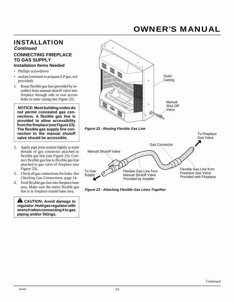
Figure 22 - Routing Flexible Gas Line
CONNECTING FIREPLACETO GAS SUPPLYInstallation Items Needed• Phillips screwdriver
• sealant (resistant to propane/LP gas, notprovided)
1. Route flexible gas line (provided by in-staller) from manual shutoff valve intofireplace through side or rear accessholes in outer casing (see Figure 22).
NOTICE: Most building codes donot permit concealed gas con-nections. A flexible gas line isprovided to allow accessibilityfrom the fireplace (see Figure 23).The flexible gas supply line con-nection to the manual shutoffvalve should be accessible.
ManualShut OffValve
Flexible Gas Line fromFireplace Gas ValveProvided with Fireplace
To FireplaceGas Valve
2. Apply pipe joint sealant lightly to malethreads of gas connector attached toflexible gas line (see Figure 23). Con-nect flexible gas line to flexible gas lineattached to gas valve of fireplace (seeFigure 23).
3. Check all gas connections for leaks. SeeChecking Gas Connections, page 14.
4. Feed flexible gas line into fireplace basearea. Make sure the entire flexible gasline is in fireplace mantel base area.
➞Figure 23 - Attaching Flexible Gas Lines Together
Gas Connector
Flexible Gas Line fromManual Shutoff ValveProvided by Installer
Manual Shutoff Valve
➞To GasSupply
CAUTION: Avoid damage toregulator. Hold gas regulator withwrench when connecting it to gaspiping and/or fittings.
Continued
OuterCasing

14 105442
VENT-FREE PROPANE/LP BAY FRONT FIREPLACE CF26PR
OPOSIT
PO
Open
Closed
ManualShutoffValve
Figure 25 - Checking Gas Joints (Shown with Optional Mantel)
Figure 24 - Manual Shutoff Valve
ManualShutoffValve
Propane/LPSupply Tank
Pressure Testing Gas SupplyPiping SystemTest Pressures In Excess Of 1/2 PSIG1. Disconnect fireplace and its individual
manual shutoff valve from gas supplypiping system. Pressures in excess of1/2 psig will damage fireplace regulator.
2. Cap off open end of gas pipe wheremanual shutoff valve was connected.
3. Pressurize supply piping system by ei-ther using compressed air or openingpropane/LP supply tank valve.
4. Check all joints of gas supply pipingsystem. Apply mixture of liquid soapand water to gas joints. Bubbles form-ing show a leak.
5. Correct all leaks at once.6. Reconnect heater and manual shutoff
valve to gas supply. Check reconnectedfittings for leaks.
INSTALLATIONContinuedCHECKING GASCONNECTIONS
WARNING: Test all gas pip-ing and connections for leaksafter installing or servicing. Cor-rect all leaks at once.
WARNING: Never use an openflame to check for a leak. Apply amixture of liquid soap and waterto all joints. Bubbles forming showa leak. Correct all leaks at once.
CAUTION: Make sure externalregulator has been installed be-tween propane/LP supply and fire-place. See guidelines under Con-necting to Gas Supply , page 12.
Test Pressures Equal To or Less Than1/2 PSIG1. Close manual shutoff valve (see
Figure 24).2. Pressurize supply piping system by ei-
ther using compressed air or openingpropane/LP supply tank valve.
3. Check all joints from propane/LP sup-ply tank to manual shutoff valve (seeFigure 25). Apply mixture of liquidsoap and water to gas joints. Bubblesforming show a leak.
4. Correct all leaks at once.
Pressure Testing Fireplace GasConnections1. Open manual shutoff valve (see
Figure 24).
2. Open propane/LP supply tank valve.
3. Make sure control knob of fireplace isin the OFF position.
4. Check all joints from manual shutoffvalve to thermostat gas valve (see Fig-ure 23, page 13). Apply mixture of liq-uid soap and water to gas joints.Bubbles forming show a leak.
5. Correct all leaks at once.
6. Light fireplace (see Operating Fire-place, pages 15 through 17). Check allother internal joints for leaks.
7. Turn off fireplace (see To Turn Off Gasto Appliance, page 16).
8. Replace front panel.

15105442
OWNER’S MANUAL
WARNING: Failure to positionthe parts in accordance with thesediagrams or failure to use onlyparts specifically approved withthis heater may result in propertydamage or personal injury.
INSTALLING LOGS
It is very important to install the logs exactlyas instructed. Do not modify logs. Only uselogs supplied with heater.
Place one-piece log set on grate to fit asillustrated in Figure 26. Make sure backsection of log set is seated into “U”-shapedcutout in center of chassis (see Figure 26).IMPORTANT: Make sure log does not coverany burner ports (see Figure 27).
CAUTION: After installationand periodically thereafter, checkto ensure that no flame comes incontact with any log. With theheater set to High, check to see ifflames contact any log. If so, re-position logs according to thelog installation instructions in thismanual. Flames contacting logswill create soot.
Figure 26 - Installing One-Piece Log Set
AUTOOFFON
One Piece Log Set
Burner
"U"-shapedCutout inChassis
Chassis
Figure 27 - Installing One-Piece Log set(Top View)
One Piece Log SetBurnerPorts
OPTIONAL WIRELESS HAND-HELD REMOTE CONTROLACCESSORIES(CGHRC & CGHRCT Series)
Installing Receiver1. Disconnect switch wires from the con-
trol valve.
2. Remove screws and nuts.
3. Remove switch plate (see Figure 28).Discard after removing.
4. Install remote receiver unit onto gas logheater base using clips (2) and insulat-ing washers provided.
5. Push clips firmly into place (see Fig-ure 29).
6. Connect wires as shown in Figure 30.
INSTALLATIONContinued
Figure 28 - Switch Plate and WiringHarness (Switch Plate and OrientationMay Vary Depending On Model)
Front
Back
Wires
Nut
Nut
Screw
Front
Front
Back
Figure 29 - Installing Remote ReceiverInsulating Washers
RemoteReceiver
MountingClips
Back
Back
INSTALLING WIRELESSREMOTE CONTROLACCESSORYTwo 9-volt alkaline batteries (not included)are required to operate this heater with thewireless hand held remote control set. Onebattery must be installed in the receiver andone in the hand-held remote control unit.Note: Only use alkaline batteries.
Installing 9-Volt Battery inReceiver1. Locate back of receiver under front
burner of heater.
2. Locate the battery clip mounted on theback of the receiver.
3. Slide a 9-volt battery through the clip.
4. Attach the terminal wires to the battery.
Figure 31 - Installing Receiver on theBack of the Base
Figure 30 - Connecting Wires
Red Wire FromReceiver
Valve
White WireFrom Receiver
Front
BatteryClip9-Volt
Battery
Receiver
TerminalWires
Continued

16 105442
VENT-FREE PROPANE/LP BAY FRONT FIREPLACE CF26PR
LIGHTINGINSTRUCTIONS
1. STOP! Read the safety information,column 2.
2. Make sure manual shutoff valve isfully open.
3. Set switch in OFF position.
NOTICE: During initial operationof new heater, burning logs willgive off a paper-burning smell.Open a window to vent smell. Thiswill only last a few hours.
WARNING: Burner will comeon automatically within one minutewhen the selector switch is in theON position after the pilot is lit.
Figure 33 - Control Knob and Ignitor Button Location (Shown asSupplied, No Control Options)
OFF
PILOTON
L O
IH
AUTOOFFON
Control KnobIgnitor Button Selector Switch
Flame Adjustment Knob
4. Press in and turn control knob clock-wise to the OFF position.
5. Wait five (5) minutes to clear out anygas. Then smell for gas, includingnear the floor. If you smell gas,STOP! Follow “B” in the safety in-formation. If you don’t smell gas, goto the next step.
6. Press in and turn control knob coun-terclockwise to the PILOTposition. Press in control knob forfive (5) seconds (see Figure 33).Note: You may be running thisheater for the first time after hook-ing up to gas supply. If so, the con-trol knob may need to be pressed infor 30 seconds or more. This will al-low air to bleed from the gas system.
7. With control knob pressed in, pressand release ignitor button. This willlight pilot. The pilot is attached to thefront burner. If needed, keep press-ing ignitor button until pilot lights.
Installing 9-Volt Battery (NotIncluded) in Hand-Held RemoteControl Unit1. Remove battery cover on back of re-
mote control unit.
2. Attach terminal wires to the battery.Place battery into the battery housing.
3. Replace battery cover onto remote con-trol unit.
Figure 32 - Installing Battery in Hand-Held Remote Control Unit
INSTALLATIONContinued
BatteryCover
9-VoltBattery
TerminalWires
RemoteControl Unit
BatteryHousing
OPERATINGFIREPLACE
FOR YOUR SAFETYREAD BEFORE
LIGHTING
WARNING: If you do not fol-low these instructions exactly, afire or explosion may result caus-ing property damage, personalinjury or loss of life.
A. This appliance has a pilot which mustbe lighted by hand. When lighting thepilot, follow these instructions exactly.
B. BEFORE LIGHTING smell allaround the appliance area for gas. Besure to smell next to the floor becausesome gas is heavier than air and willsettle on the floor.WHAT TO DO IF YOU SMELLGAS• Do not try to light any appliance.• Do not touch any electric switch; do
not use any phone in your building.• Immediately call your gas supplier
from a neighbor’s phone. Followthe gas supplier’s instructions.
• If you cannot reach your gas sup-plier, call the fire department.
C. Use only your hand to push in or turnthe gas control knob. Never use tools.If the knob will not push in or turnby hand, don’t try to repair it, call aqualified service technician or gassupplier. Force or attempted repairmay result in a fire or explosion.
D. Do not use this appliance if any parthas been under water. Immediatelycall a qualified service technician toinspect the appliance and to replaceany part of the control system andany gas control which has been un-der water.

17105442
OWNER’S MANUAL
IMPORTANT: This remote control hasbeen specially engineered to take an airtemperature sample every 5.5 minutes inthe auto mode. It will not respond imme-diately to the temperature setting beingturned up or down.
OPERATINGHEATERContinued
TO TURN OFF GASTO APPLIANCE
Shutting Off Heater1. Turn control knob clockwise
to the OFF position.2a. Set selector switch in the OFF position2b. If Using Optional Hand-Held Re-
mote: Set selector switch in the OFFposition to keep from draining battery.
Shutting Off Burner Only (pilotstays lit)
You may shut off the burner and keep thepilot lit by doing one of the following:1. Turn control knob clockwise
to the PILOT position.2. Use remote control manual OFF button.3. Set selector switch in the OFF position.
MANUAL LIGHTINGPROCEDURE
Thermostat Control Operation
(Optional CGHRCT Series Only) Thethermostat control setting on the remotecontrol unit can be set to any comfortlevel between HI and LO. The burner willturn on and off automatically to maintainthe comfort level you select. The idealcomfort setting will vary by householddepending upon the amount of space tobe heated, the output of the central heat-ing system, etc.
1. Follow steps 1 through 6 under Light-ing Instructions, page 16.
2. Depress control knob and light pilotwith match.
3. Keep control knob pressed in for 30seconds after lighting pilot. After 30seconds, release control knob. Nowfollow steps 9 through 11, column 1.
OPTIONAL REMOTEOPERATION
NOTICE: You must light the pilotbefore using the hand-held re-mote control unit. See LightingInstructions on page 16 and 17.
Note: All remote control accessories mustbe purchased separately (see Accessories,page 28). Follow instructions includedwith the remote control.
1. After lighting, let pilot flame burn forabout one minute. Turn control knobto ON position. Adjust flame adjust-ment knob anywhere between HIand LO. Slide the selector switch tothe REMOTE position. NOTE: Theburner may light if hand-held remoteON button was on when selectorswitch was last turned off. You cannow turn the burner on and off withthe hand-held remote control unit.
IMPORTANT: Do not leave the selectorswitch in the REMOTE position when thepilot is not lit. This will drain the battery.
IMPORTANT: Be sure to press the ON/OFF buttons on the hand held remotecontrol unit for up to 3 seconds to assureproper operation.
CGHRC Operation:2a. Press the ON/OFF button to turn the
burner on and off. When turningburner off, the pilot will remain lit.
CGHRCT Operation2b. Select the MAN (manual) or AUTO
button on the hand-held remote con-trol unit (see Figure 36, page 18)• In manual mode, turn burner on
or off by pressing the ON or OFFbuttons on the hand-held remotecontrol unit.
• In auto mode, the room tempera-ture is controlled by the thermo-stat in the hand-held remote con-trol unit. To increase the room tem-perature, press the top arrow of theTEMP button. To lower room thetemperature, press the bottom ar-row of the TEMP button. At highersettings the heater will run more.
Note: If pilot does not stay lit, con-tact a qualified service person or gassupplier for repairs. Until repairs aremade, light pilot with match. To lightpilot with match, see Manual Light-ing Procedure.
8. Keep control knob pressed in for 30seconds after lighting pilot. After 30seconds, release control knob.• If control knob does not pop out when
released, contact a qualified serviceperson or gas supplier for repairs.Note: If pilot goes out, repeat steps4 through 8.
9. Slightly push in and turn controlknob counterclockwise to theON position.
10. Wait one minute and switch selectorswitch to the ON position to lightburner. Note: AUTO is only func-tional when using GWMT1 orGWMS2 optional accessories.
11. Set flame adjustment knob to anylevel between HI and LO.
CAUTION: Do not try to adjustheating levels by using themanual shutoff valve.
WARNING: Make sure theselector switch is in the OFF po-sition when you are away fromhome for long periods of time.Heater will come on automati-cally with selector switch in theON position.
Figure 34 - Pilot
IgnitorElectrode
Pilot Burner
Continued

18 105442
VENT-FREE PROPANE/LP BAY FRONT FIREPLACE CF26PR
OPERATINGHEATERContinued
TEMP
STATUS
HI
LOMAN ON
AUTO OFF
Increases RoomTemperature
Decreases RoomTemperature
Turns Burner Onand Off
Shows CurrentOperation Mode
Shows Temperature Setting
Allows burner to be turnedon and off with the hand-held remote unit.
Figure 36 - Thermostat Hand-Held Remote Control Unit Selections (CGHRCT only)
The Log heater willautomatically cycle betweenpilot and the heat setting thathas been selected.
Figure 35 - Setting the Selector Switch, Control Knob, and FlameAdjustment Knob for Remote Operation
Selector Switch in Remote Position (OptionalRemote Control)
ONOFFREMOTE
OFF
PILOTO
NL O
IH
Control Knob inOn PositionFlame Adjustment Knob
Figure 37 - Correct Pilot Flame Pattern
Pilot Burner
Thermocouple
Figure 38 - Incorrect Pilot Flame Pattern
Check pilot flame pattern and burner flamepatterns often.
PILOT FLAME PATTERNFigure 37 shows a correct pilot flame pat-tern. Figure 38 shows an incorrect pilotflame pattern. The incorrect pilot flame isnot properly heating the thermocouple.When the thermocouple cools, the heaterwill shut down.
If pilot flame pattern is incorrect, as shownin Figure 38
• turn heater off (see To Turn Off Gas toAppliance, page 16)
• see Troubleshooting, pages 20 through 22
Pilot Burner
Thermocouple
INSPECTINGBURNERS
BURNER PRIMARY AIR HOLESAir is drawn into the burner through theholes in the fitting at the burner entrance.These holes may become blocked with dustor lint. Periodically inspect these holes forany blockage and clean if needed. Blockedair holes will create soot.
MAIN BURNERPeriodically inspect all burner flame holeswith the heater running. All slotted burnerflame holes should be open with yellowflame present. All round burner flame holesshould be open with a small blue flamepresent. Some burner flame holes may be-come blocked by debris or rust, with no flamepresent. If so, turn off heater and let cool.Either remove blockage or replace burner.Blocked burner flame holes will create soot.
IMPORTANT: The hand-held remote con-trol unit must be near the heater. Do notkeep the hand-held remote control unittoo close to the heater. The thermostat onthe hand-held remote control unit willheat up too quickly and turn the heater off.3. Use the STATUS button on the hand-
held remote control unit to see the
operation mode being used and thetemperature setting selected. A redlight will come on beside the opera-tion mode being used when the sta-tus button is pressed.
4. To turn the burner off when operatingin the manual mode, press the OFFbutton. If operating in the auto mode,press the MAN button, then press theOFF button. The pilot will remain lit.IMPORTANT: To turn the pilot off,manually turn the control knob on theheater to the OFF position.

19105442
OWNER’S MANUAL
CLEANING ANDMAINTENANCE
WARNING: Turn off heaterand let cool before cleaning.
CAUTION: You must keepcontrol areas, burner, and circu-lating air passageways of heaterclean. Inspect these areas ofheater before each use. Haveheater inspected yearly by a quali-fied service person. Heater mayneed more frequent cleaning dueto excessive lint from carpeting,pet hair, etc.
CABINETAir Passageways• Use a vacuum cleaner or pressurized air
to clean.
Exterior• Use a soft cloth dampened with a mild
soap and water mixture. Wipe the cabi-net to remove dust.
REPLACEMENTPARTSNote: Use only original replacement parts.This will protect your warranty coveragefor parts replaced under warranty.
PARTS UNDER WARRANTYContact authorized dealers of this product.If they can’t supply original replacementpart(s) call DESA International’s TechnicalService Department at 1-800-323-5190 forreferral information.
When calling DESA International, haveready
• your name
• your address
• model and serial numbers of your fire-place
• how fireplace was malfunctioning
• type of gas used (propane/LP or naturalgas)
• purchase date
Usually, we will ask you to return the defec-tive part to the factory.
PARTS NOT UNDERWARRANTYContact authorized dealers of this productor Parts Central (see page 23). If they can’tsupply original replacement part(s) callDESA International’s Parts Department at1-800-972-7879 for referral information.
When calling DESA International, haveready
• model number of your fireplace
• the replacement part number
CLEANING BURNERINJECTOR HOLDER ANDPILOT AIR INLET HOLEThe primary air inlet holes allow the properamount of air to mix with the gas. Thisprovides a clean burning flame. Keep theseholes clear of dust, dirt, and lint. Clean theseair inlet holes prior to each heating season.Blocked air holes will create soot. We rec-ommend that you clean the unit every 2,500hours of operation or every three months.
We also recommend that you keep the burnertube and pilot assembly clean and free of dustand dirt. To clean these parts we recommendusing compressed air no greater than 30 PSI.Your local computer store, hardware store, orhome center may carry compressed air in acan. You can use a vacuum cleaner in theblow position. If using compressed air in acan, please follow the directions on the can.If you don't follow directions on the can, youcould damage the pilot assembly.
1. Shut off the unit, including the pilot.Allow the unit to cool for at least thirtyminutes.
2. Inspect burner, pilot, and primary airinlet holes on injector holder for dustand dirt (see Figure 39).
3. Blow air through the ports/slots andholes in the burner.
4. Check the injector holder located at theend of the burner tube again. Remove anylarge particles of dust, dirt, lint, or pet hairswith a soft cloth or vacuum cleaner nozzle.
Figure 39 - Injector Holder On OutletBurner Tube
5. Blow air into the primary air holes onthe injector holder.
6. In case any large clumps of dust havenow been pushed into the burner repeatsteps 3 and 4.
Clean the pilot assembly also. A yellow tip onthe pilot flame indicates dust and dirt in the pilotassembly. There is a small pilot air inlet holeabout two inches from where the pilot flamecomes out of the pilot assembly (see Figure 40).With the unit off, lightly blow air through the airinlet hole. You may blow through a drinkingstraw if compressed air is not available.
BurnerTube
Injector Holder(May Be Brassor AluminumDepending onModel)
Primary Air InletHoles (Shape ofHoles May Varyby Model)
Figure 40 - Pilot Inlet Air Hole
BurnerTube
PilotAssembly
Pilot AirInletHole
Ports/Slots
20 105442
VENT-FREE PROPANE/LP BAY FRONT FIREPLACE CF26PR
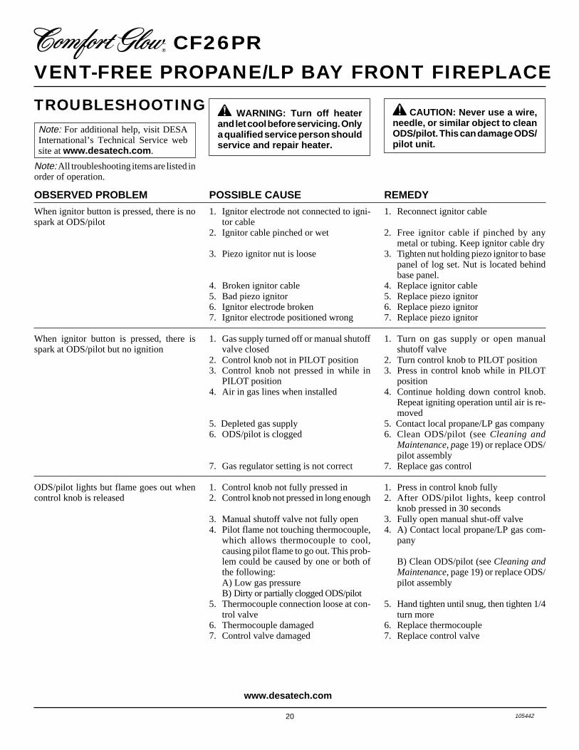
TROUBLESHOOTING WARNING: Turn off heater
and let cool before servicing. Onlya qualified service person shouldservice and repair heater.
CAUTION: Never use a wire,needle, or similar object to cleanODS/pilot. This can damage ODS/pilot unit.
POSSIBLE CAUSE
1. Ignitor electrode not connected to igni-tor cable
2. Ignitor cable pinched or wet
3. Piezo ignitor nut is loose
4. Broken ignitor cable5. Bad piezo ignitor6. Ignitor electrode broken7. Ignitor electrode positioned wrong
1. Gas supply turned off or manual shutoffvalve closed
2. Control knob not in PILOT position3. Control knob not pressed in while in
PILOT position4. Air in gas lines when installed
5. Depleted gas supply6. ODS/pilot is clogged
7. Gas regulator setting is not correct
1. Control knob not fully pressed in2. Control knob not pressed in long enough
3. Manual shutoff valve not fully open4. Pilot flame not touching thermocouple,
which allows thermocouple to cool,causing pilot flame to go out. This prob-lem could be caused by one or both ofthe following:A) Low gas pressureB) Dirty or partially clogged ODS/pilot
5. Thermocouple connection loose at con-trol valve
6. Thermocouple damaged7. Control valve damaged
REMEDY
1. Reconnect ignitor cable
2. Free ignitor cable if pinched by anymetal or tubing. Keep ignitor cable dry
3. Tighten nut holding piezo ignitor to basepanel of log set. Nut is located behindbase panel.
4. Replace ignitor cable5. Replace piezo ignitor6. Replace piezo ignitor7. Replace piezo ignitor
1. Turn on gas supply or open manualshutoff valve
2. Turn control knob to PILOT position3. Press in control knob while in PILOT
position4. Continue holding down control knob.
Repeat igniting operation until air is re-moved
5. Contact local propane/LP gas company6. Clean ODS/pilot (see Cleaning and
Maintenance, page 19) or replace ODS/pilot assembly
7. Replace gas control
1. Press in control knob fully2. After ODS/pilot lights, keep control
knob pressed in 30 seconds3. Fully open manual shut-off valve4. A) Contact local propane/LP gas com-
pany
B) Clean ODS/pilot (see Cleaning andMaintenance, page 19) or replace ODS/pilot assembly
5. Hand tighten until snug, then tighten 1/4turn more
6. Replace thermocouple7. Replace control valve
OBSERVED PROBLEM
When ignitor button is pressed, there is nospark at ODS/pilot
When ignitor button is pressed, there isspark at ODS/pilot but no ignition
ODS/pilot lights but flame goes out whencontrol knob is released
Note: For additional help, visit DESAInternational’s Technical Service website at www.desatech.com .
Note: All troubleshooting items are listed inorder of operation.
www.desatech.com

21105442
OWNER’S MANUAL
TROUBLESHOOTINGContinued
OBSERVED PROBLEM
Burner does not light after ODS/pilot is lit
Delayed ignition burner
Burner backfiring during combustion
Slight smoke or odor during initial operation
Moisture/condensation noticed on windows
Heater produces a whistling noise whenburner is lit
White powder residue forming within burnerbox or on adjacent walls or furniture
Remote does not function
REMEDY
1. Clean burner (see Cleaning and Mainte-nance, page 19) or replace burner orifice
2. Contact local propane/LP gas company3. Replace burner orifice4. Reconnect leads (see Wiring Diagram,
page 23)5. Replace battery in transmitter and re-
ceiver
1. Contact local propane/LP gas company2. Clean burner (see Cleaning and Mainte-
nance, page 19) or replace burner orifice
1. Clean burner (see Cleaning and Mainte-nance, page 19) or replace burner orifice
2. Replace damaged burner3. Replace gas control
1. Check burner for dirt and debris. Iffound, clean burner (see Cleaning andMaintenance, page 19)
2. Replace gas control3. Problem will stop after a few hours of
operation
1. Refer to Air for Combustion and Venti-lation requirements (page 4)
1. Turn control knob to LO position andlet warm up for a minute
2. Operate burner until air is removed fromline. Have gas line checked by local pro-pane/LP gas company
3. Observe minimum installation clear-ances (see pages 7 through 9)
4. Clean burner (see Cleaning and Mainte-nance, page 19) or replace burner orifice
1. Turn heater off when using furniturepolish, wax, carpet cleaners, or similarproducts
1. Replace 9-volt batteries in receiver andremote control
POSSIBLE CAUSE
1. Burner orifice clogged
2. Inlet gas pressure is too low3. Burner orifice diameter is too small4. Thermopile leads disconnected or im-
properly connected5. Burners will not come on in remote po-
sition
1. Manifold pressure is too low2. Burner orifice clogged
1. Burner orifice is clogged or damaged
2. Damaged burner3. Gas regulator defective
1. Not enough air
2. Gas regulator defective3. Residues from manufacturing processes
and logs curing
1. Not enough combustion/ventilation air
1. Turning control knob to HI positionwhen burner is cold
2. Air in gas line
3. Air passageways on heater blocked
4. Dirty or partially clogged burner orifice
1. When heated, vapors from furniture pol-ish, wax, carpet cleaners, etc. turn intowhite powder residue
1. Battery is not installed. Battery poweris low
www.desatech.com Continued

22 105442
VENT-FREE PROPANE/LP BAY FRONT FIREPLACE CF26PR
WARNING: If you smell gas• Shut off gas supply.• Do not try to light any appliance.• Do not touch any electrical switch; do not use any phone in your
building.• Immediately call your gas supplier from a neighbor’s phone. Follow the
gas supplier’s instructions.• If you cannot reach your gas supplier, call the fire department.
POSSIBLE CAUSE
1. Metal expanding while heating or con-tracting while cooling
1. Heater burning vapors from paint, hairspray, glues, cleaners, chemicals, newcarpet, etc. (See IMPORTANT state-ment above)
2. Gas leak. See Warning statement attop of page
1. Not enough fresh air is available2. Low line pressure3. ODS/pilot is partially clogged
1. Gas leak. See Warning statement attop of page
2. Control valve defective
1. Foreign matter between control valveand burner
2. Gas leak. See Warning statement attop of page
OBSERVED PROBLEM
Heater produces a clicking/ticking noisejust after burner is lit or shut off
Heater produces unwanted odors
Heater shuts off in use (ODS operates)
Gas odor even when control knob is in OFFposition
Gas odor during combustion
REMEDY
1. This is common with most heaters. Ifnoise is excessive, contact qualified ser-vice person
1. Open window and ventilate room. Stopusing odor causing products while heateris running
2. Locate and correct all leaks (see Check-ing Gas Connections, page 14)
1. Open window and/or door for ventilation2. Contact local natural gas company3. Clean ODS/pilot (see Cleaning and
Maintenance, page 19)
1. Locate and correct all leaks (see Check-ing Gas Connections, page 14)
2. Replace control valve
1. Take apart gas tubing and remove for-eign matter
2. Locate and correct all leaks (see Check-ing Gas Connections, page 14)
IMPORTANT: Operating heater where impurities in air exist may create odors. Cleaningsupplies, paint, paint remover, cigarette smoke, cements and glues, new carpet or textiles,etc., create fumes. These fumes may mix with combustion air and create odors. These odorswill disappear over time.
TROUBLESHOOTINGContinued
www.desatech.com

23105442
OWNER’S MANUAL
TECHNICALSERVICEYou may have further questions about in-stallation, operation, or troubleshooting.
If so, contact DESA International’s Techni-cal Service Department at 1-800-DESA LOG(1-800-337-2564).
You can also visit DESA International’sTechnical Services web site atwww.desatech.com.
SPECIFICATIONS
When Gas Pressure Is Too Low• pilot will not stay lit
• burners will have delayed ignition
• heater will not produce specified heat
• propane/LP gas supply may be low
When Gas Quality Is Bad• pilot will not stay lit
• burners will produce flames and soot
• heater will backfire when lit
You may feel your gas pressure is too low orgas quality is bad. If so, contact your localnatural gas supplier.
SERVICE HINTS
PARTS CENTRALS Tarantin Tank Co.P.O. Box 6129Freehold, NJ 07728-6129908-780-93401-800-922-0724Parts Department
Heater & Fireplace Store1922 N Route 9Cape May Court, NJ 08210-1110609-624-0678Parts Department
Dayton HardwareP.O. Box 275North Dayton StationDayton, OH 45404-0275All States937-258-3721Parts Department1-800-762-3426
Halco Enterprises208 Carter Drive, Unit 21West Chester, PA 19382-4500610-430-77171-800-368-0803Parts Department
LaPorte’s Parts & Service2444 North 5th StreetHartsville, SC 29550-7704803-332-0191Parts Department
Cans Unlimited, Inc.P.O. Box 645Taylor, SC 29687-0013All States803-879-30091-800-845-5301Parts Department
Baltimore Electric1348 Dixwell AvenueHamden, CT 06514-03221-800-397-7553203-248-7553Parts Department
Portable Heater Parts342 N. County Rd. 400 EastValparaiso, IN 46383-9704All States219-462-74411-800-362-6951Parts Department
FBD1349 Adams St.Bowling Green, KY 42103-3413502-846-11991-800-654-8534Fax: 1-800-846-0090
Four Flags Power Products1115 Stateline RoadNiles, MI 49120-4728616-684-26971-800-268-4983Parts Only
Master Parts Distributors1251 Mound Ave. NWGrand Rapids, MI 49504-3458616-791-0505Fax: 1-616-791-8270Parts Department1-800-446-1446
Washer Equipment Co.1715 Main StreetKansas City, MO 64108-2195KS, MO, AR816-842-3911Parts Department
East Coast Energy Products707 BroadwayW. Long Branch, NJ 07764-1542732-870-88091-800-755-8809Parts Department
These Parts Centrals are privately ownedbusinesses. They have agreed to support ourcustomer’s needs by providing original re-placement parts and accessories.
Btu (Variable) 19,000/26,000Type Gas Propane/LP OnlyIgnition PiezoManifold Pressure 8" W.C.Inlet Gas Pressure (in. of water) *
Maximum 14"Minimum 11"
Dimensions, Inches (H x W x D)Fireplace 25 7/8 x 27 x 13 3/4Carton 28 x 26 13/16 x 16 1/2
Weight, poundsFireplace 44 1/2 lbs.Shipping 55 lbs.
* For purposes of input adjustment
WIRING DIAGRAM
Switch
BlackAutoOffOn
Red
Red
WhiteThermopile
Gas Control TPTH TH
THTPTH TP
TP
24 105442
VENT-FREE PROPANE/LP BAY FRONT FIREPLACE CF26PR
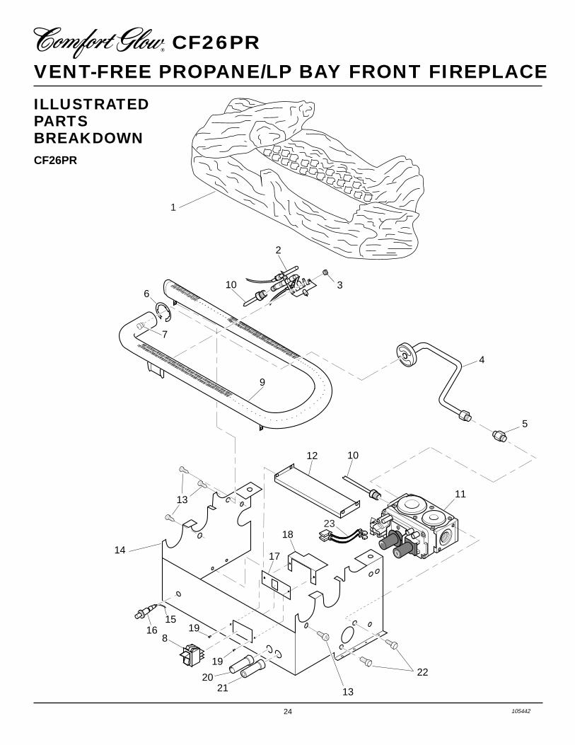
ILLUSTRATEDPARTSBREAKDOWNCF26PR
O
FF
P
ILOT
O
N
H
I
LO
O
FF
P
ILOT
O
N
H
I
LO
1615
198
19
2021
17
18
14
13
23
1012
22
13
4
7
6
9
5
11
10 3
2
1

25105442
OWNER’S MANUAL
PARTS LISTCF26PR
This list contains replaceable parts used in your heater. When ordering parts, follow theinstructions listed under Replacement Parts on page 19 of this manual.
KEY PARTNO. NUMBER DESCRIPTION QTY.
1 105441-01 Log Set 12 103778-01 ODS Pilot (LP) 13 098249-01 ODS Nut 24 104422-04 Burner Outlet Tube 15 098264-02 Male Connector 16 102843-01 Burner Clip 17 099056-21 Burner Orifice Injector 18 099998-01 Switch 19 102980-01 Burner 110 099387-13 Pilot Tube 111 103781-02 Gas Control Valve 112 103345-02 Lower Bracket 113 M11084-38 Screw, #8 x .38 714 104384-04 Base Assy 115 098271-07 Ignitor Cable 116 102445-01 Piezo Ignitor 117 103587-02 Plate, Switch 118 104099-01 Heat Shield 119 098304-01 Screw 220 103784-02 Flame Adjustment Knob 121 103784-01 Off-Pilot-On Knob 122 M12461-26 Screw, Hex Slt Wsr 10-32 x .38 423 103284-02 Wiring Harness
PARTS AVAILABLE — NOT SHOWN
100563-01 Warning Plate 1103877-01 Lighting Instructions Plate 1

26 105442
VENT-FREE PROPANE/LP BAY FRONT FIREPLACE CF26PR
ILLUSTRATEDPARTSBREAKDOWNCF26PR
5
8
15
17
13
14
11-2
11-1
21
19
4
12
16
10
6
5
9
1
2
18
7
20-2
20-3
20-1
18
18
16
22
3
18
16
3
22

27105442
OWNER’S MANUAL
PARTS LISTCF26PR
KEY CF26PRNO. PART NO. DESCRIPTION QTY.
1 102633-02CK Outer Casing Top 12 102624-02 Outer Casing 13 099230-02 Shoulder Screw 124 105631-01 Assy. Hood Weldment 15 105258-01CK Vertical Front, Left and Right Sides 26 105259-01 Firebox Top 17 105260-01CJ Firebox Wrapper 18 105255-01 Bayfront Base 19 105421-01 Heat Deflector 110 105409-01 Fan Control Shield 111-1 105401-01 Screen Rod 111-2 105440-01 Screen Assembly 112 101386-02 Hinge 213 099194-11 Rivets 814 105262-01CK Louvered Door 115 105261-01CK Firebox Floor 116 098304-01 Screw, #10 x 3/8" 2117 105256-01CK Bayfront Bottom Panel 118 M11084-26 Hex Head Screws #10 x .38 2619 105513-01CV Cover, Screen Rod 120-1 105525-01 Fiber Brick, Left 120-2 105524-01 Fiber Brick, Rear 120-3 105526-01 Fiber Brick, Right 121 105784-01 Screen Clip 122 105987-01 Brick Liner Retainer 2
PARTS AVAILABLE — NOT SHOWN
103877-01 Lighting Instructions Plate 1100563-01 Warning Plate 1103470-01 Hardware Package 1104319-03 Information Video 1
This list contains replaceable parts used in your fireplace. When ordering parts, follow theinstructions listed under Replacement Parts on page 19 of this manual.

28 105442
VENT-FREE PROPANE/LP BAY FRONT FIREPLACE CF26PR
ACCESSORIESPurchase these fireplace accessories fromyour local dealer or Parts Central (see page23). If they cannot supply these accessoriescall DESA International’s Sales Depart-ment at 1-800-458-2472 for referral infor-mation. You can also write to the addresslisted on the back page of this manual.
CABINET MANTEL WITHBUILT-IN HEARTH BASE
Unfinished Hardwood Veneer-GMC46UWhite Lacquer Finish - GMC47WMedium Stained Oak Veneer-GMC45F
For use with fireplace. A hardwood manteland hearth base offers compact styling andcompletes the fireplace look. Available in awhite lacquer finish, medium stained oak,or an unfinished hardwood, ready to stain orpaint. Complete assembly instructions in-cluded. Three-sided brass trim kit included.
MANUAL SHUTOFF VALVEGA5010
Manual shutoff valve with 1/8" NPT tap.
THERMOSTATICALLYCONTROLLED BLOWER KITGA3450T
Provides better heat distribution. Blowerturns off and on automatically, as needed.Complete installation and operating instruc-tions included.
AUTO
MAN
OFF
STATUS
ON
LO
HI
TEMP
RECEIVER AND HAND-HELDTHERMOSTAT REMOTECONTROL KIT - CGHRCTSERIESAllows the gas log heater to be operated ina manually or thermostatically controlledmode. You can turn the gas log heater on andoff without ever leaving the comfort of youreasy chair.
RECEIVER AND HAND-HELDREMOTE CONTROL KIT -CGHRC SERIESAllows the gas log heater to be turned on andoff by using a hand-held remote control.
BRASS ACCENT TRIMGA7092 (Not Shown)Optional two piece brass trim kit for theBayfront Fireplace. Easily screws to fire-place front. Provides an upscale appearance.
AUTOOFFON

29105442
OWNER’S MANUAL
NOTES_______________________________________________________________________________________________
_______________________________________________________________________________________________
_______________________________________________________________________________________________
_______________________________________________________________________________________________
_______________________________________________________________________________________________
_______________________________________________________________________________________________
_______________________________________________________________________________________________
_______________________________________________________________________________________________
_______________________________________________________________________________________________
_______________________________________________________________________________________________
_______________________________________________________________________________________________
_______________________________________________________________________________________________
_______________________________________________________________________________________________
_______________________________________________________________________________________________
_______________________________________________________________________________________________
_______________________________________________________________________________________________
_______________________________________________________________________________________________
_______________________________________________________________________________________________
_______________________________________________________________________________________________
_______________________________________________________________________________________________
_______________________________________________________________________________________________
_______________________________________________________________________________________________
_______________________________________________________________________________________________
_______________________________________________________________________________________________
_______________________________________________________________________________________________
_______________________________________________________________________________________________
_______________________________________________________________________________________________
_______________________________________________________________________________________________
_______________________________________________________________________________________________
_______________________________________________________________________________________________
_______________________________________________________________________________________________
_______________________________________________________________________________________________
_______________________________________________________________________________________________
_______________________________________________________________________________________________

2701 Industrial DriveP.O. Box 90004Bowling Green, KY 42102-9004
www.desatech.com
INTERNATIONAL
105442-01REV. A06/99
LIMITED WARRANTYVENT-FREE PROPANE/LP GAS HEARTH‚ FIREPLACE
DESA International warrants this product to be free from defects in materials and components for two (2) years from the date of firstpurchase, provided that the product has been properly installed, operated and maintained in accordance with all applicable instructions.To make a claim under this warranty the Bill of Sale or cancelled check must be presented.
This warranty is extended only to the original retail purchaser. This warranty covers the cost of part(s) required to restore this fireplace toproper operating condition and an allowance for labor when provided by a DESA Authorized Service Center. Warranty part(s) MUST beobtained through authorized dealers of this product and/or DESA International who will provide original factory replacement parts. Failureto use original factory replacement parts voids this warranty. The fireplace MUST be installed by a qualified installer in accordance withall local codes and instructions furnished with the unit.
This warranty does not apply to parts that are not in original condition because of normal wear and tear, or parts that fail or become damagedas a result of misuse, accidents, lack of proper maintenance or defects caused by improper installation. Travel, diagnostic cost, labor,transportation and any and all such other costs related to repairing a defective fireplace will be the responsibility of the owner.
TO THE FULL EXTENT ALLOWED BY THE LAW OF THE JURISDICTION THAT GOVERNS THE SALE OF THE PRODUCT;THIS EXPRESS WARRANTY EXCLUDES ANY AND ALL OTHER EXPRESSED WARRANTIES AND LIMITS THE DURATIONOF ANY AND ALL IMPLIED WARRANTIES, INCLUDING WARRANTIES OF MERCHANTABILITY AND FITNESS FOR APARTICULAR PURPOSE TO TWO (2) YEARS ON ALL COMPONENTS FROM THE DATE OF FIRST PURCHASE; AND DESAINTERNATIONAL’S LIABILITY IS HEREBY LIMITED TO THE PURCHASE PRICE OF THE PRODUCT AND DESA INTERNA-TIONAL SHALL NOT BE LIABLE FOR ANY OTHER DAMAGES WHATSOEVER INCLUDING INDIRECT, INCIDENTAL ORCONSEQUENTIAL DAMAGES.
Some states do not allow a limitation on how long an implied warranty lasts or an exclusion or limitation of incidental or consequentialdamages, so the above limitation on implied warranties, or exclusion or limitation on damages may not apply to you.
This warranty gives you specific legal rights, and you may also have other rights that vary from state to state.
For information about this warranty write:
KEEP THIS WARRANTY
Model
Serial No.
Date Purchased
Always specify model and serial numbers when communicating with the factory.
We reserve the right to amend these specifications at any time without notice. The only warranty applicable is our standard written warranty.We make no other warranty, expressed or implied.
WARRANTY INFORMATION
NOT A UPC105442 01