Embed Size (px)
Citation preview
ZXDSL 931WIIVDSL2 Modem
Maintenance Management Manual
Version: 3.1
ZTE CORPORATIONNO. 55, Hi-tech Road South, ShenZhen, P.R.ChinaPostcode: 518057Tel: +86-755-26771900Fax: +86-755-26770801URL: http://ensupport.zte.com.cnE-mail: [email protected]

LEGAL INFORMATIONCopyright © 2011 ZTE CORPORATION.
The contents of this document are protected by copyright laws and international treaties. Any reproduction or
distribution of this document or any portion of this document, in any form by any means, without the prior written
consent of ZTE CORPORATION is prohibited. Additionally, the contents of this document are protected by
contractual confidentiality obligations.
All company, brand and product names are trade or service marks, or registered trade or service marks, of ZTE
CORPORATION or of their respective owners.
This document is provided “as is”, and all express, implied, or statutory warranties, representations or conditions
are disclaimed, including without limitation any implied warranty of merchantability, fitness for a particular purpose,
title or non-infringement. ZTE CORPORATION and its licensors shall not be liable for damages resulting from the
use of or reliance on the information contained herein.
ZTE CORPORATION or its licensors may have current or pending intellectual property rights or applications
covering the subject matter of this document. Except as expressly provided in any written license between ZTE
CORPORATION and its licensee, the user of this document shall not acquire any license to the subject matter
herein.
ZTE CORPORATION reserves the right to upgrade or make technical change to this product without further notice.
Users may visit ZTE technical support website http://ensupport.zte.com.cn to inquire related information.
The ultimate right to interpret this product resides in ZTE CORPORATION.
Revision History
Revision No. Revision Date Revision Reason
R1.0 2011-07-10 First Edition
Serial Number: SJ-20110627155502-001
Publishing Date: 2011-07-10(R1.0)

ContentsAbout This Manual ......................................................................................... I
Chapter 1 Safety Precautions.................................................................... 1-1
Chapter 2 Overview.................................................................................... 2-12.1 Product Introduction ........................................................................................... 2-1
2.2 Packing List ....................................................................................................... 2-1
2.3 Product Features................................................................................................ 2-2
2.4 Interfaces .......................................................................................................... 2-2
2.5 Indicators........................................................................................................... 2-3
2.6 Technical Specifications...................................................................................... 2-4
Chapter 3 Configuration Preparation ....................................................... 3-13.1 Hardware Connection ......................................................................................... 3-1
3.2 Configuring TCP/IP ............................................................................................ 3-3
3.3 Logging In to the Device ..................................................................................... 3-4
Chapter 4 Status......................................................................................... 4-14.1 Device Information ............................................................................................. 4-1
4.2 Network Interface ............................................................................................... 4-1
4.2.1 VDSL Connection..................................................................................... 4-2
4.2.2 3G Status ................................................................................................ 4-2
4.2.3 ADSL WAN Connection ............................................................................ 4-3
4.2.4 Mobile Network ........................................................................................ 4-3
4.2.5 DSL Link Information ................................................................................ 4-4
4.3 User Interface .................................................................................................... 4-4
4.3.1 WLAN ..................................................................................................... 4-4
4.3.2 Ethernet................................................................................................... 4-5
4.3.3 USB ........................................................................................................ 4-5
Chapter 5 Network...................................................................................... 5-15.1 WAN ................................................................................................................. 5-1
5.1.1 VDSL Connection Settings........................................................................ 5-1
5.1.2 3G WAN Connection ................................................................................ 5-4
5.1.3 ADSL Connection Settings........................................................................ 5-6
5.1.4 Port Binding ............................................................................................. 5-9
5.1.5 DSL Modulation ..................................................................................... 5-10
5.2 WLAN ............................................................................................................. 5-10
I

5.2.1 Basic IEEE 802.11n Configuration ............................................................5-11
5.2.2 SSID Settings ........................................................................................ 5-12
5.2.3 Security ................................................................................................. 5-14
5.2.4 Access Control List................................................................................. 5-16
5.2.5 Associated Devices ................................................................................ 5-17
5.3 LAN................................................................................................................. 5-18
5.3.1 DHCP Server ......................................................................................... 5-18
5.3.2 IPv6 DHCP Server ................................................................................. 5-20
5.3.3 DHCP Binding........................................................................................ 5-21
5.3.4 DHCP Conditional Serving Pool .............................................................. 5-22
5.3.5 DHCP Port Service................................................................................. 5-23
5.3.6 Static Prefix ........................................................................................... 5-24
5.3.7 Prefix Delegation.................................................................................... 5-26
5.3.8 Port Service ........................................................................................... 5-27
5.3.9 RA Service ............................................................................................ 5-27
5.4 Routing............................................................................................................ 5-28
5.4.1 Default Gateway .................................................................................... 5-29
5.4.2 Static Routing ........................................................................................ 5-30
5.4.3 Policy Routing........................................................................................ 5-31
5.4.4 Routing Table......................................................................................... 5-33
5.5 IPv6 Routing .................................................................................................... 5-33
5.5.1 Default Gateway .................................................................................... 5-34
5.5.2 Static Routing ........................................................................................ 5-34
5.5.3 Routing Table......................................................................................... 5-36
Chapter 6 Security...................................................................................... 6-16.1 Firewall.............................................................................................................. 6-1
6.2 IP Filter.............................................................................................................. 6-2
6.3 MAC Filter ......................................................................................................... 6-4
6.4 Parent Control.................................................................................................... 6-6
6.4.1 User Information ...................................................................................... 6-6
6.4.2 URL Filter ................................................................................................ 6-7
6.4.3 Port Filter................................................................................................. 6-8
6.5 Service Control ................................................................................................ 6-10
6.6 ALG ................................................................................................................ 6-12
Chapter 7 Application ................................................................................ 7-17.1 DDNS................................................................................................................ 7-1
7.2 DMZ Host .......................................................................................................... 7-3
II

7.3 UPnP ................................................................................................................ 7-4
7.4 UPnP Port Mapping............................................................................................ 7-6
7.5 Port Forwarding ................................................................................................. 7-6
7.6 DNS Service ...................................................................................................... 7-8
7.6.1 Domain Name.......................................................................................... 7-8
7.6.2 Hosts....................................................................................................... 7-9
7.6.3 DNS ...................................................................................................... 7-10
7.7 QoS .................................................................................................................7-11
7.7.1 Basic ......................................................................................................7-11
7.7.2 Classification ......................................................................................... 7-13
7.8 SNTP .............................................................................................................. 7-14
7.9 IGMP............................................................................................................... 7-15
7.9.1 WAN Connection.................................................................................... 7-16
7.9.2 Basic Configuration ................................................................................ 7-16
7.10 MLD .............................................................................................................. 7-17
7.10.1 MLD Snooping ..................................................................................... 7-17
7.10.2 MLD Proxy........................................................................................... 7-18
7.11 USB Storage .................................................................................................. 7-19
7.12 DMS.............................................................................................................. 7-20
7.13 FTP Application.............................................................................................. 7-22
7.14 Dynamic Routing ............................................................................................ 7-23
7.15 Port Trigger.................................................................................................... 7-24
Chapter 8 Administration........................................................................... 8-18.1 TR-069 Management.......................................................................................... 8-1
8.1.1 Configuring TR-069 basic parameters........................................................ 8-1
8.1.2 Managing TR-069 certificate ..................................................................... 8-3
8.2 User Management.............................................................................................. 8-4
8.3 System Management.......................................................................................... 8-6
8.3.1 System Management................................................................................ 8-6
8.3.2 Software Upgrade .................................................................................... 8-7
8.3.3 User Configuration Management ............................................................... 8-8
8.3.4 Default Configuration Management ........................................................... 8-9
8.4 Log Management ............................................................................................. 8-10
8.5 Mobile Network Management............................................................................ 8-12
8.5.1 PIN Management ................................................................................... 8-13
8.5.2 Network Mode........................................................................................ 8-13
8.6 Diagnosis ........................................................................................................ 8-14
III

8.6.1 Ping Diagnosis ....................................................................................... 8-15
8.6.2 Trace Route Diagnosis ........................................................................... 8-16
8.6.3 AT Diagnosis.......................................................................................... 8-17
8.6.4 Mirror Configuration................................................................................ 8-18
8.6.5 Ethernet Diagnosis ................................................................................. 8-19
8.6.6 PPPoE Diagnosis................................................................................... 8-20
8.6.7 DNS Diagnosis....................................................................................... 8-20
8.6.8 IP Diagnosis .......................................................................................... 8-21
8.7 WAN Type ....................................................................................................... 8-22
Figures............................................................................................................. I
Tables .............................................................................................................V
Index .............................................................................................................VII
Glossary ........................................................................................................IX
IV

About This ManualPurpose
The ZXDSL 931WII is a VDSL2 access device that supports multiple transmission modes.It provides 4 FE Ethernet interfaces, one USB 2.0 interface, and one IEEE 802.11 b/g/nWi-Fi interface. The ZXDSL 931WII provides broadband Internet service and enterprisenetwork access service through the high-speed DSL or 3G wireless access mode.
Moreover, the ZXDSL 931WII provides secure wireless encryption modes and firewall toprotect network security and supports remote network management through TR-069 andWeb GUI.
Intended Audience
This document is intended for:
l Network planning engineerl Installation debugging engineerl On-site maintenance engineerl Network monitoring engineerl System maintenance engineerl Data configuration engineer
What Is in This Manual
This manual contains the following chapters:
Chapter Summary
Chapter 1, Safety Precautions Provides the safety precautions for this manual.
Chapter 2, Overview Provides the product packing list, product features, interfaces,
indicators, and technical specifications.
Chapter 3, Configuration
Preparation
Describes the hardware connection, TCP/IP configuration, and
login procedure.
Chapter 4, Status Describes how to view the device status.
Chapter 5, Network Describes the network configuration, including broadband
configuration, WLAN configuration, address management,
routing management, and IPv6 management.
Chapter 6, Security Describes the configuration of the firewall, IP filter, MAC filter,
parent control, and access control.
I

Chapter Summary
Chapter 7, Application Describes the configuration of DDNS, DMZ, UPnP, UPnP
port mapping, port forwarding, DNS service, QoS, SNTP,
IGMP, MLD, DMS, FTP application, dynamic routing, and port
triggering.
Chapter 8, Administration Describes the configuration of TR-069, user management,
system management, log management, mobile network
management, diagnosis, and WAN type.
Conventions
ZTE documents employ the following typographical conventions.
Typeface Meaning
Italics References to other Manuals and documents.
“Quotes” Links on screens.
Bold Menus, menu options, function names, input fields, radio button names, check
boxes, drop-down lists, dialog box names, window names.
CAPS Keys on the keyboard and buttons on screens and company name.
Note: Provides additional information about a certain topic.
Checkpoint: Indicates that a particular step needs to be checked before
proceeding further.
Tip: Indicates a suggestion or hint to make things easier or more productive
for the reader.
Mouse operation conventions are listed as follows:
Typeface Meaning
Click Refers to clicking the primary mouse button (usually the left mouse button) once.
Double-click Refers to quickly clicking the primary mouse button (usually the left mouse button)
twice.
Right-click Refers to clicking the secondary mouse button (usually the right mouse button)
once.
II

Chapter 1Safety PrecautionsBefore using the device, read the following safety precautions. ZTE bears no liability tothe consequences incurred by violation of the safety instructions.
l Read the user manuals before using the device.l Pay attention to all the cautions in the user manuals and on the product.l To avoid fire or product damage, do not use accessories that are not related to this
product.l Use the power adapter delivered with the device.l Do not put anything on the device.l Keep the device dry, clean, and well-ventilated.l In thunder days, disconnect the device from the power supply to avoid thunder attack.l Use soft and dry cloth to clean the device. Do not use liquid or spray to clean the
device. Before cleaning the device, disconnect the power supply.l Keep the air vent clean. Anything that dropping down into the device through the air
vent may cause short circuit and lead to device damage or fire.l Keep any liquid away from the device surface.l Do not open the shell of the device, especially when the device is powered ON.
1-1
SJ-20110627155502-001|2011-07-10(R1.0) ZTE Proprietary and Confidential

ZXDSL 931WII Maintenance Management Manual
This page intentionally left blank.
1-2
SJ-20110627155502-001|2011-07-10(R1.0) ZTE Proprietary and Confidential
Chapter 2OverviewTable of Contents
Product Introduction ...................................................................................................2-1Packing List................................................................................................................2-1Product Features........................................................................................................2-2Interfaces ...................................................................................................................2-2Indicators ...................................................................................................................2-3Technical Specifications .............................................................................................2-4
2.1 Product IntroductionThe ZXDSL 931WII is a VDSL2 service access device. The ZXDSL 931WII provides thebroadband Internet service and enterprise network access service through the high-speedDSL or 3G wireless access mode. The ZXDSL 931WII provides four 10/100Base-TEthernet user interfaces and the wireless access function that complies with the IEEE802.11b/g/n standard.
2.2 Packing ListAfter opening the ZXDSL 931WII packing box, make sure that it contains the followingcomponents, as listed in Table 2-1.
Table 2-1 Packing List
Item Name Quantity
ZXDSL 931WII unit 1
AC-DC power adapter 1
2-1
SJ-20110627155502-001|2011-07-10(R1.0) ZTE Proprietary and Confidential

ZXDSL 931WII Maintenance Management Manual
Item Name Quantity
Separator 1
RJ-45 network cable 1
RJ-11 telephone cable 2
The ZXDSL 931WII VDSL2 Modem Maintenance Management Manual is delivered withthe product.
If any of the components are incorrect, lost, or damaged, contact the product agency. Ifyou want to change the product, keep the packing box and components.
2.3 Product FeaturesThe ZXDSL 931WII supports the following features:
l Four 10/100 Mbps Ethernet interfacesl Network configuration through friendly GUIl IPSec VPNl DHCP server functionsl Compatible with all the Internet standard applicationsl Standard and compatible DSL interfacel Virtual server, IP address filter, and DMZ functionl System configuration in web model Software upgrade through downloadl Upstream modes includes ADSL, ADSL2, ADSL2+, and VDSL2, LAN, and 3G
WCDMA.l PPPoE, IPoE, and StaticIP sessions, each mode supporting up to eight sessionsl RIP v1, RIP v2, and NAT protocoll Wireless LAN IEEE 802.11b, 802.11g, and 802.11n protocols
2.4 InterfacesFigure 2-1 shows the ZXDSL 931WII interfaces and buttons.
2-2
SJ-20110627155502-001|2011-07-10(R1.0) ZTE Proprietary and Confidential

Chapter 2 Overview
Figure 2-1 Interfaces and Buttons
Table 2-2 lists the description of the ZXDSL 931WII interfaces and buttons.
Table 2-2 Interfaces and Buttons
Interface/Button Description
PWR 12V DC power connector
On/Off Power button
Reset Reset button
When the power is on, use a needle to press the button for over 10 seconds
to restore the default settings.
WPS WPS access switch
WLAN WLAN button, switch on/off WLAN
USB USB HOST port, connected to the storage device or 3G USB network card
LAN1–LAN4 RJ-45 Ethernet interfaces
DSL RJ-11 DSL interface
2.5 IndicatorsTable 2-3 lists the indicators on the front panel.
Table 2-3 Indicators on the Front Panel
Indicator Color Status Description
Green/Red OFF The device is powered OFF.
Red ON The device is powered ON but fails to work
properly.
Power
Green ON The device is powered ON and works
properly.
2-3
SJ-20110627155502-001|2011-07-10(R1.0) ZTE Proprietary and Confidential

ZXDSL 931WII Maintenance Management Manual
Indicator Color Status Description
OFF The WPS connection is complete.
Flashing slowly The WPS connection is being established.
ON The WPS connection is successful.
WPS Green
Flashing fast The WPS connection fails.
OFF The device is powered OFF or the line has
no signal.
Flashing The DSL connection tries synchronization
and training.
DSL Green
ON The DSL connection is in synchronization
state.
OFF The device is powered OFF or the DSL
connection is not synchronized.
Flashing There is upstream or downstream data flow
passing through the user-end device.
Internet Green
ON The WAN connection is established.
OFF NO USB storage device is connected.USB Green
ON l A USB storage device is connected to
the USB port.
l A 3G network card is connected to the
USB port.
OFF No SSID is working.
Flashing At least one SSID is transmitting data.
WLAN Green
ON At least one SSID works properly.
OFF The device is powered OFF. No network
cable is connected to the device or no
online user-end device is connected to the
user-side interface.
ON The user-side interface is connected to a
user-end device and works properly.
LAN 1–LAN 4 Green
Flashing There is data flow passing through the
user-side interface.
2.6 Technical SpecificationsTable 2-4 lists the ZXDSL 931WII technical specifications.
2-4
SJ-20110627155502-001|2011-07-10(R1.0) ZTE Proprietary and Confidential

Chapter 2 Overview
Table 2-4 Technical Specifications
Item Specification
Dimension 200 mm × 40 mm × 141 mm (Width × Height ×
Depth)
Rated current 1.5 A
Rated voltage DC 12 V
Operation temperature 0℃–40℃
Operation humidity 20%–90%
Storage temperature 20℃–70℃
Storage humidity 5%–95%
2-5
SJ-20110627155502-001|2011-07-10(R1.0) ZTE Proprietary and Confidential

ZXDSL 931WII Maintenance Management Manual
This page intentionally left blank.
2-6
SJ-20110627155502-001|2011-07-10(R1.0) ZTE Proprietary and Confidential

Chapter 3Configuration PreparationTable of Contents
Hardware Connection.................................................................................................3-1Configuring TCP/IP ....................................................................................................3-3Logging In to the Device.............................................................................................3-4
3.1 Hardware ConnectionFigure 3-1 shows the entire connection between the ZXDSL 931WII and other devices.
Figure 3-1 Entire Connection
1. DSL interface2. LAN interface
3. USB interface4. Reset button
5. Power button6. Power interface
The connections between the ZXDSL 931WII and other devices are as follows:
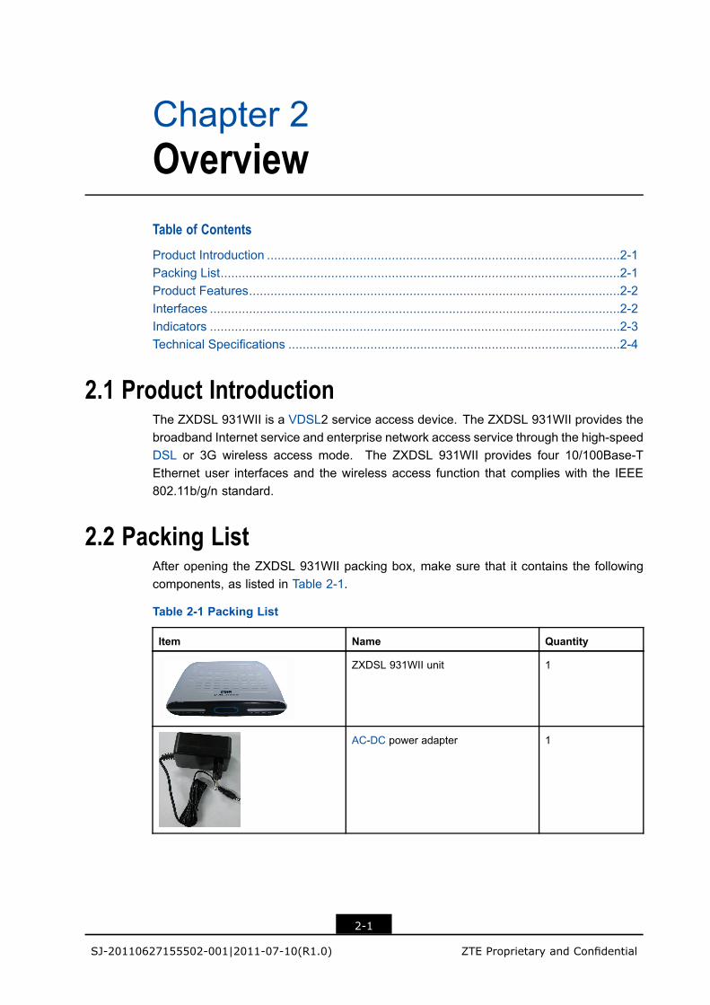
l Figure 3-2 shows the connection between the ZXDSL 931WII and the computer.
3-1
SJ-20110627155502-001|2011-07-10(R1.0) ZTE Proprietary and Confidential
ZXDSL 931WII Maintenance Management Manual
Figure 3-2 LAN Interface Connection
l Figure 3-3 shows the connection between the ZXDSL 931WII and the separator.
Figure 3-3 Separator Connection
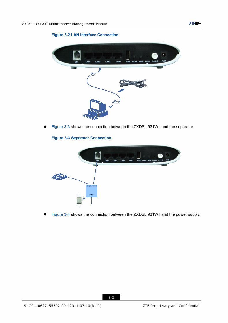
l Figure 3-4 shows the connection between the ZXDSL 931WII and the power supply.
3-2
SJ-20110627155502-001|2011-07-10(R1.0) ZTE Proprietary and Confidential
Chapter 3 Configuration Preparation
Figure 3-4 Power Supply Connection
To supply power for the device, press the power button, as shown in Figure 3-5.
Figure 3-5 Pressing the Power Button
When the ZXDSL 931WII DSL indicator is ON, you can access the Internet.
3.2 Configuring TCP/IPShort Description
Perform this procedure to configure TCP/IP.
Context
To ensure that the device accesses the Internet successfully, configure the computeraddress in the same network segment as the ZXDSL 931WII address.
The default network settings for the ZXDSL 931WII are as follows:
l IP address: 192.168.1.1l Subnet mask: 255.255.255.0l Default gateway: 192.168.1.1
To configure TCP/IP, perform the following steps:
3-3
SJ-20110627155502-001|2011-07-10(R1.0) ZTE Proprietary and Confidential

ZXDSL 931WII Maintenance Management Manual
Steps1. Configure TCP/IP.
a. In Local Area Connection Properties, select Internet Protocol (TCP/IP).
b. Click Properties to open the Internet Protocol (TCP/IP) Properties dialog box.
c. In the Internet Protocol (TCP/IP) Properties dialog box, select Use thefollowing IP address. Set IP address, Subnet mask and Default gateway.Set the computer IP address to be in the same network segment as the deviceaddress, for example, 192.168.1.7. The subnet mask is 255.255.255.0 and thedefault gateway is 192.168.1.1.
d. Click OK.
Note:
The settings change with different network requirements. However, perform thesteps above at the first time.
2. Check the TCP/IP settings.
You can use the Ping command to check the connection between the computer anddevice.
If the computer fails to ping the device, check the following items:
l The Ethernet cable between the device and the computer is correctly connected.l The driver program of the network adapter on the computer is correctly installed.l The LAN indicator on the device and the network card indicator on the computer
are ON.l The TCP/IP settings on the computer are correct.
– End of Steps –
ResultTCP/IP is configured successfully.
3.3 Logging In to the DeviceShort Description
Perform this procedure to log in to the device.
PrerequisitesBefore this operation, make sure that the device is properly connected and the computeris correctly configured.
3-4
SJ-20110627155502-001|2011-07-10(R1.0) ZTE Proprietary and Confidential
Chapter 3 Configuration Preparation
Context
The ZXDSL 931WII provides the web-based configuration mode. You can configure andmanage the device through the web browser. Different users have different configurationrights, as listed in Table 3-1.
Table 3-1 User Rights
Role User Name and Password Right
Administrator User name: admin
Password: admin
All the configuration rights
Common user User name: user
Password: user
The common users only have some view rights.
To log in to the device, perform the following steps:
Steps
1. Open the Internet Explorer.
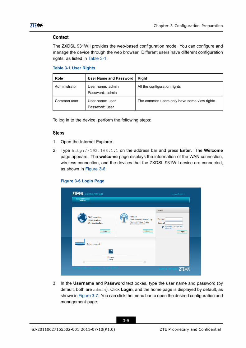
2. Type http://192.168.1.1 on the address bar and press Enter. The Welcomepage appears. The welcome page displays the information of the WAN connection,wireless connection, and the devices that the ZXDSL 931WII device are connected,as shown in Figure 3-6
Figure 3-6 Login Page
3. In the Username and Password text boxes, type the user name and password (bydefault, both are admin). Click Login, and the home page is displayed by default, asshown in Figure 3-7. You can click the menu bar to open the desired configuration andmanagement page.
3-5
SJ-20110627155502-001|2011-07-10(R1.0) ZTE Proprietary and Confidential

ZXDSL 931WII Maintenance Management Manual
Figure 3-7 Home Page
1. Menu bar 2. Configuration andmanagement area
3. Help area
Note:
The Web configuration pages may vary with the software versions. The configurationpages for the administrator and user accounts are different. The administrator accountis used as an example in this manual.
– End of Steps –
Result
You have logged in to the device successfully.
3-6
SJ-20110627155502-001|2011-07-10(R1.0) ZTE Proprietary and Confidential

Chapter 4StatusTable of Contents
Device Information .....................................................................................................4-1Network Interface .......................................................................................................4-1User Interface.............................................................................................................4-4
4.1 Device InformationOn the menu bar, click Status > Device Information. The device information is displayed,as shown in Figure 4-1.
Figure 4-1 Device Information
4.2 Network InterfaceThis section includes the following:
l VDSL WAN connectionl 3G statusl ADSL WAN connectionl Mobile networkl DSL link information
4-1
SJ-20110627155502-001|2011-07-10(R1.0) ZTE Proprietary and Confidential
ZXDSL 931WII Maintenance Management Manual
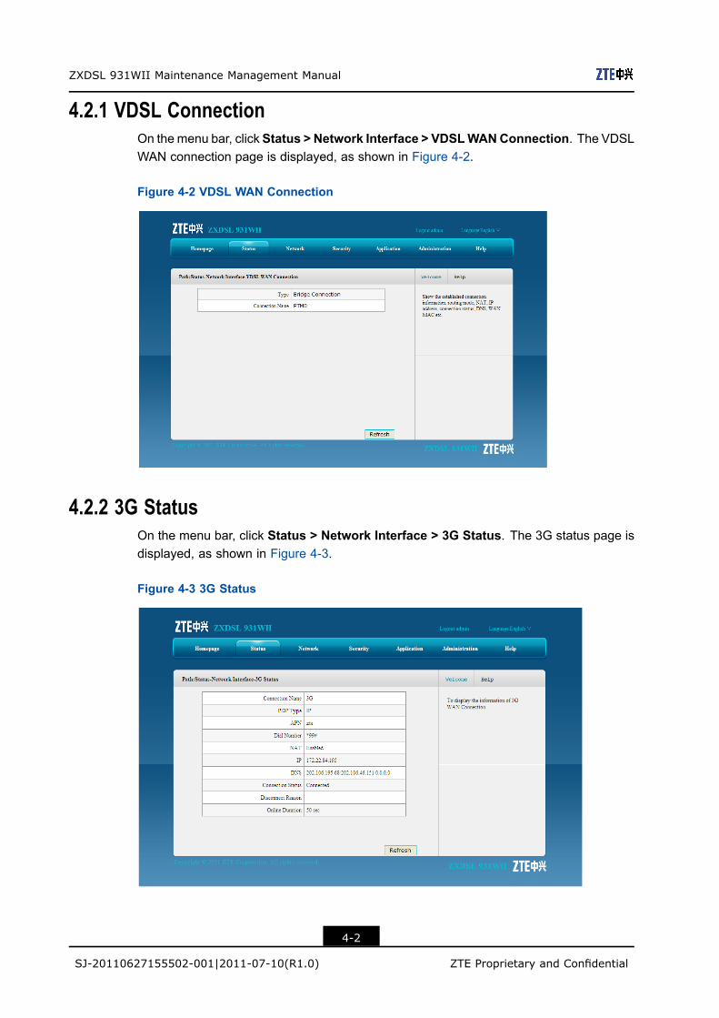
4.2.1 VDSL ConnectionOn themenu bar, click Status > Network Interface > VDSLWANConnection. The VDSLWAN connection page is displayed, as shown in Figure 4-2.
Figure 4-2 VDSL WAN Connection
4.2.2 3G StatusOn the menu bar, click Status > Network Interface > 3G Status. The 3G status page isdisplayed, as shown in Figure 4-3.
Figure 4-3 3G Status
4-2
SJ-20110627155502-001|2011-07-10(R1.0) ZTE Proprietary and Confidential
Chapter 4 Status
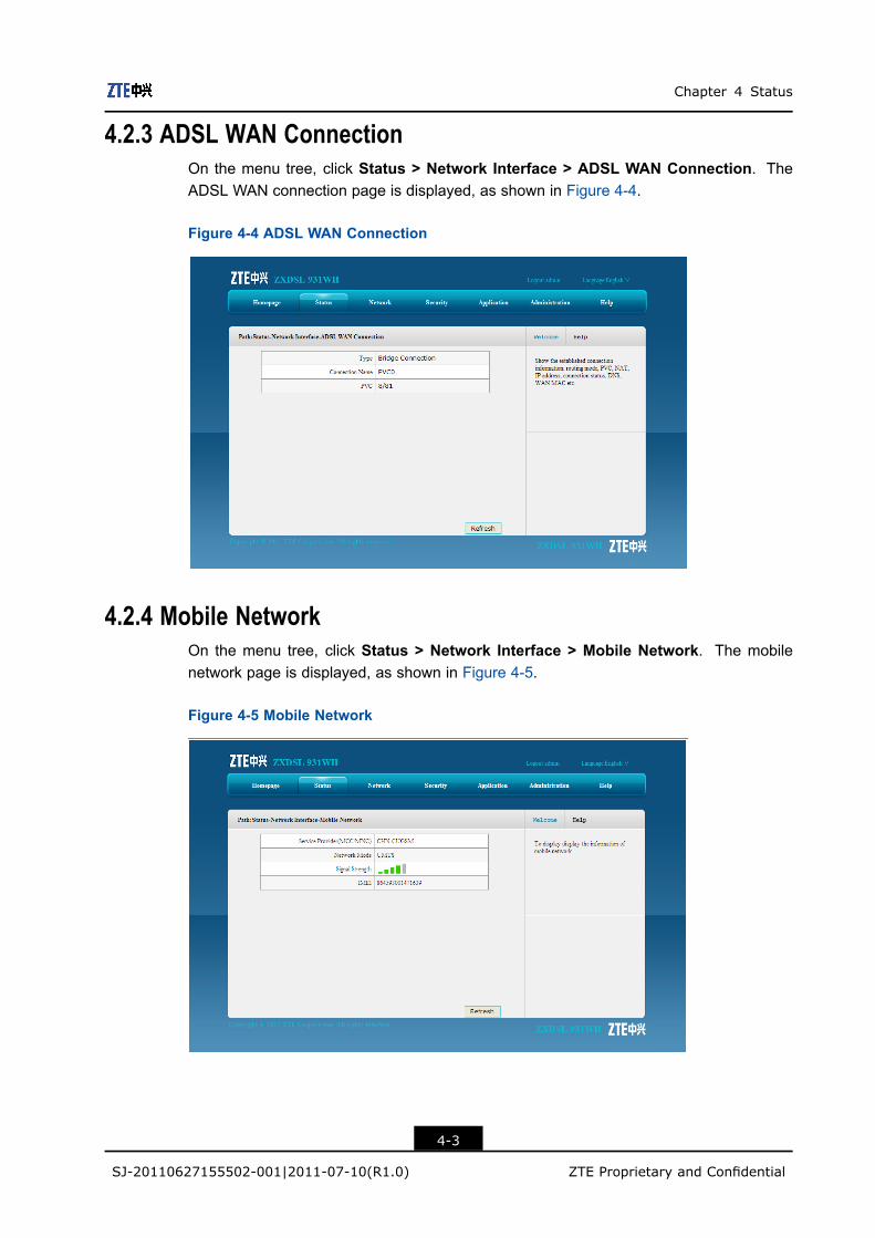
4.2.3 ADSL WAN ConnectionOn the menu tree, click Status > Network Interface > ADSL WAN Connection. TheADSL WAN connection page is displayed, as shown in Figure 4-4.
Figure 4-4 ADSL WAN Connection
4.2.4 Mobile NetworkOn the menu tree, click Status > Network Interface > Mobile Network. The mobilenetwork page is displayed, as shown in Figure 4-5.
Figure 4-5 Mobile Network
4-3
SJ-20110627155502-001|2011-07-10(R1.0) ZTE Proprietary and Confidential
ZXDSL 931WII Maintenance Management Manual
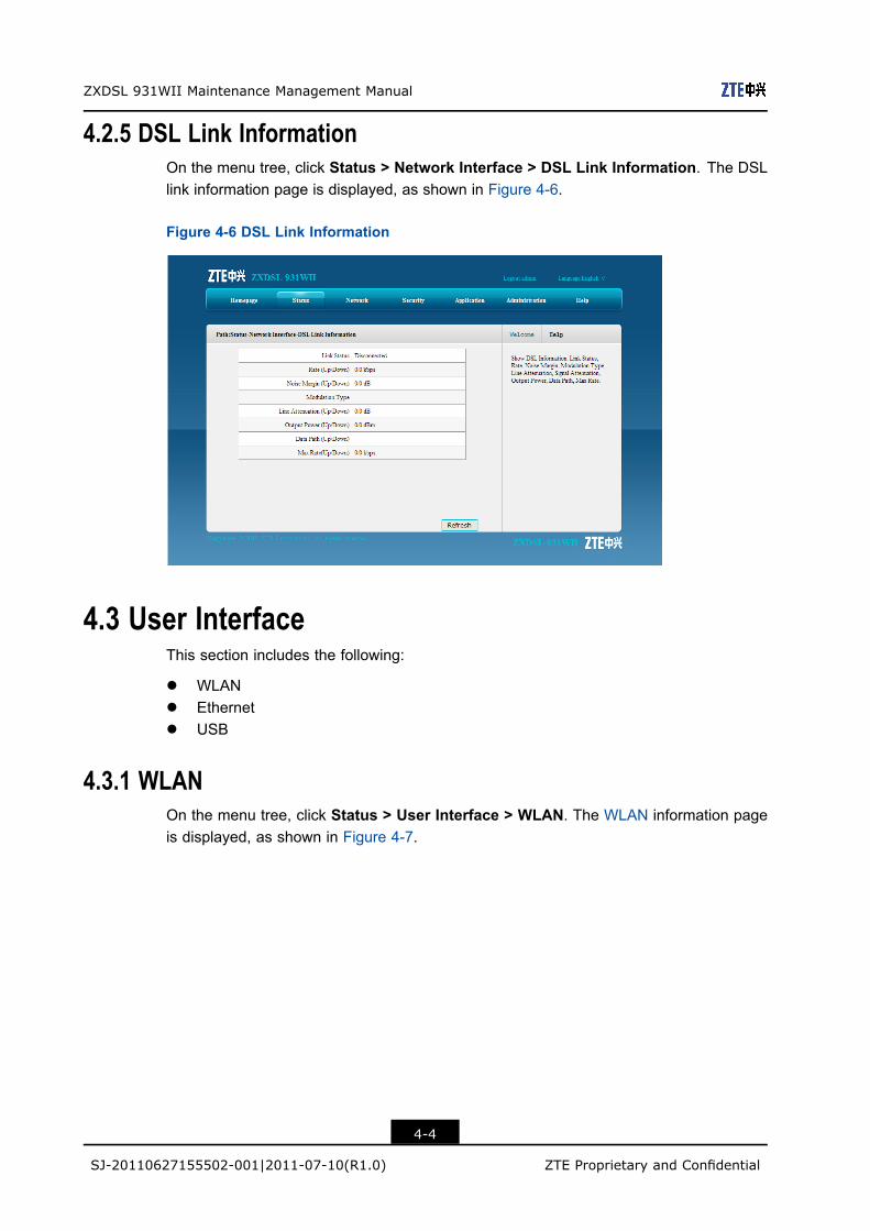
4.2.5 DSL Link InformationOn the menu tree, click Status > Network Interface > DSL Link Information. The DSLlink information page is displayed, as shown in Figure 4-6.
Figure 4-6 DSL Link Information
4.3 User InterfaceThis section includes the following:
l WLANl Ethernetl USB
4.3.1 WLANOn the menu tree, click Status > User Interface > WLAN. The WLAN information pageis displayed, as shown in Figure 4-7.
4-4
SJ-20110627155502-001|2011-07-10(R1.0) ZTE Proprietary and Confidential

Chapter 4 Status
Figure 4-7 WLAN
4.3.2 EthernetOn the menu bar, click Status > User Interface > Ethernet. The Ethernet page isdisplayed, as shown in Figure 4-8.
Figure 4-8 Ethernet
4.3.3 USBOn the menu bar, click Status > User Interface > USB. The USB page is displayed, asshown in Figure 4-9.
4-5
SJ-20110627155502-001|2011-07-10(R1.0) ZTE Proprietary and Confidential

ZXDSL 931WII Maintenance Management Manual
Figure 4-9 USB
4-6
SJ-20110627155502-001|2011-07-10(R1.0) ZTE Proprietary and Confidential

Chapter 5NetworkTable of Contents
WAN ..........................................................................................................................5-1WLAN ......................................................................................................................5-10LAN..........................................................................................................................5-18Routing ....................................................................................................................5-28IPv6 Routing ............................................................................................................5-33
5.1 WANThis section includes the following:
l VDSL WAN connectionl 3G WAN connectionl ADSL connection settingsl Port bindingl DSL modulation
5.1.1 VDSL Connection Settings
Short Description
Perform this procedure to configure the VDSL connection.
Context
The ZXDSL 931WII supports the following VDSL connection types:
l PPPoEl Staticl IPoEl Bridge
The ZXDSL 931WII supports eight WAN connections, including 3G WAN connection andADSL WAN connection.
Steps
1. On the menu bar, click Network > WAN > VDSL WAN Connection to open the VDSLWAN connection page, as shown in Figure 5-1.
5-1
SJ-20110627155502-001|2011-07-10(R1.0) ZTE Proprietary and Confidential

ZXDSL 931WII Maintenance Management Manual
Figure 5-1 VDSL WAN Connection
Table 5-1 describes the parameters of VDSL WAN connection.
Table 5-1 VDSL WAN Connection Parameter
Parameter Description
Connection name The default is Create WAN Connection.Before creating a new connection, make sure the CreateWAN Connection option is selected.
New Connection Name Specify the name of the new WAN connection.
Enable VLAN Enable the VLAN.
VLAN ID Specify the VLAN ID.
802.1p After the VLAN option is selected, you can specify the 802.1p
value to modify the service priority.
The service priority range: 0–7
Type Connection type
l Route
l Bridge Connection
Enable DSCP This function is used together with the QoS function.
Enable it as required.
DSCP The value range is 0–63.
MTU Specify the maximum transfer unit.
Link type There are two link types:
l PPP
l IP
Username PPPoE user name provided by the ISP
5-2
SJ-20110627155502-001|2011-07-10(R1.0) ZTE Proprietary and Confidential

Chapter 5 Network
Parameter Description
Password PPPoE password provided by the ISP
Authentication Type The authentication type includes Auto, PAP, and CHAP.By default, it is Auto.
Connection Trigger There are three connection trigger modes:
l Always On: When the device is started or gets offline,
the system triggers PPPoE dialing automatically.
l On Demand: The system triggers PPPoE dialing on
demand.
l Manual: The system triggers PPPoE dialing manually.
IP Version The IP version includes:
l IPv4
l IPv6
l IPv4/v6
IP Type The IP type includes:
l Static
l DHCP
PPP TransType The transmission type of the point to point protocol
Enable NAT When multiple computers in a LAN share one IP address to
visit the Internet, NAT is used to transfer the private network
address to the public network address of the WAN port.
IP Address The IP address provided by the ISP
Subnet Mask The subnet mask provided by the ISP
Gateway The gateway address provided by the ISP
DNS Server IP Address The DNS address provided by the ISP
2. Specify the WAN connection parameters as required.l To setup a bridge connection, perform the following steps.
i. Select Bridge Connection from the Type drop-down list
ii. Specify other parameters as required, and then click Create.
l To setup a PPPoE connection, perform the following steps.
i. Select Route from the Type drop-down list.
ii. Select PPP from the Link type drop-down list.
iii. Specify the user name and password in the PPP area
iv. Specify other parameters as required, and then click Create.
l To setup a static connection, perform the following steps.
i. Select Route from the Type drop-down list.
ii. Select IP from the Link type drop-down list.
5-3
SJ-20110627155502-001|2011-07-10(R1.0) ZTE Proprietary and Confidential

ZXDSL 931WII Maintenance Management Manual
iii. Select Static from the IP Type drop-down list.
iv. Specify the IP address, subnet mask, gateway, and DNS server in the IPv4area
v. Specify other parameters as required, and then click Create.
l To setup an IPoE connection, perform the following steps.
i. Select Route from the Type drop-down list.
ii. Select IP from the Link type drop-down list.
iii. Select DHCP from the IP Type drop-down list.
iv. Specify other parameters as required, and then click Create.
– End of Steps –
ResultThe newly-created WAN connection is displayed in the Connection Name drop-down list.
5.1.2 3G WAN Connection
Short Description
Perform this procedure to configure the 3G WAN connection
ContextThe ZXDSL 931WII device supports 3G WAN connection by using the 3G USB networkcard.
Steps1. On the menu bar, click Network > WAN > 3G WAN Connection to open the 3G WAN
connection page, as shown in Figure 5-2.
5-4
SJ-20110627155502-001|2011-07-10(R1.0) ZTE Proprietary and Confidential

Chapter 5 Network
Figure 5-2 3G WAN Connection
Table 5-2 describes the parameters of the 3G WAN connection.
Table 5-2 3G WAN Connection Parameter
Parameter Description
Connection Name 3G WAN connection name
Enable NAT When multiple computers in a LAN share one IP address to
visit the Internet, NAT is used to transfer the private network
address to the public network address of the WAN port.
PDP Type There are two options: IP and PPP.
APN Access point name, provided by the ISP
Dial Number Dial number, provided by the ISP
MTU Specify the maximum transfer unit.
Username User name provided by the ISP
Password Password provided by the ISP
Authentication Type There are three options: Auto, PAP and CHAP. By default,
it is Auto.The authentication type should be the same as the
authentication type for the upper-layer device.
5-5
SJ-20110627155502-001|2011-07-10(R1.0) ZTE Proprietary and Confidential
ZXDSL 931WII Maintenance Management Manual
Parameter Description
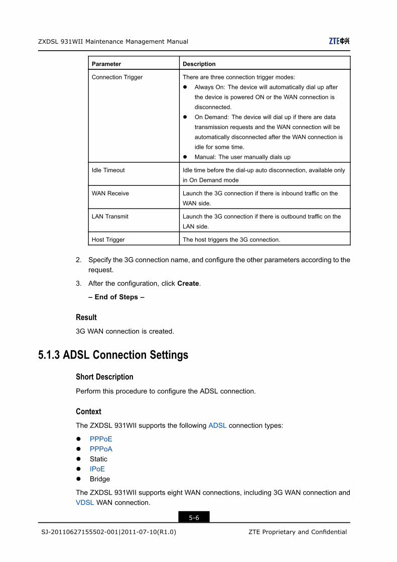
Connection Trigger There are three connection trigger modes:
l Always On: The device will automatically dial up after
the device is powered ON or the WAN connection is
disconnected.
l On Demand: The device will dial up if there are data
transmission requests and the WAN connection will be
automatically disconnected after the WAN connection is
idle for some time.
l Manual: The user manually dials up
Idle Timeout Idle time before the dial-up auto disconnection, available only
in On Demand mode
WAN Receive Launch the 3G connection if there is inbound traffic on the
WAN side.
LAN Transmit Launch the 3G connection if there is outbound traffic on the
LAN side.
Host Trigger The host triggers the 3G connection.
2. Specify the 3G connection name, and configure the other parameters according to therequest.
3. After the configuration, click Create.
– End of Steps –
Result3G WAN connection is created.
5.1.3 ADSL Connection Settings
Short Description
Perform this procedure to configure the ADSL connection.
ContextThe ZXDSL 931WII supports the following ADSL connection types:
l PPPoEl PPPoAl Staticl IPoEl Bridge
The ZXDSL 931WII supports eight WAN connections, including 3G WAN connection andVDSL WAN connection.
5-6
SJ-20110627155502-001|2011-07-10(R1.0) ZTE Proprietary and Confidential

Chapter 5 Network
Steps
1. On the menu bar, click Network > WAN > ADSL WAN Connection to open the ADSLWAN connection page, as shown in Figure 5-3.
Figure 5-3 ADSL WAN Connection
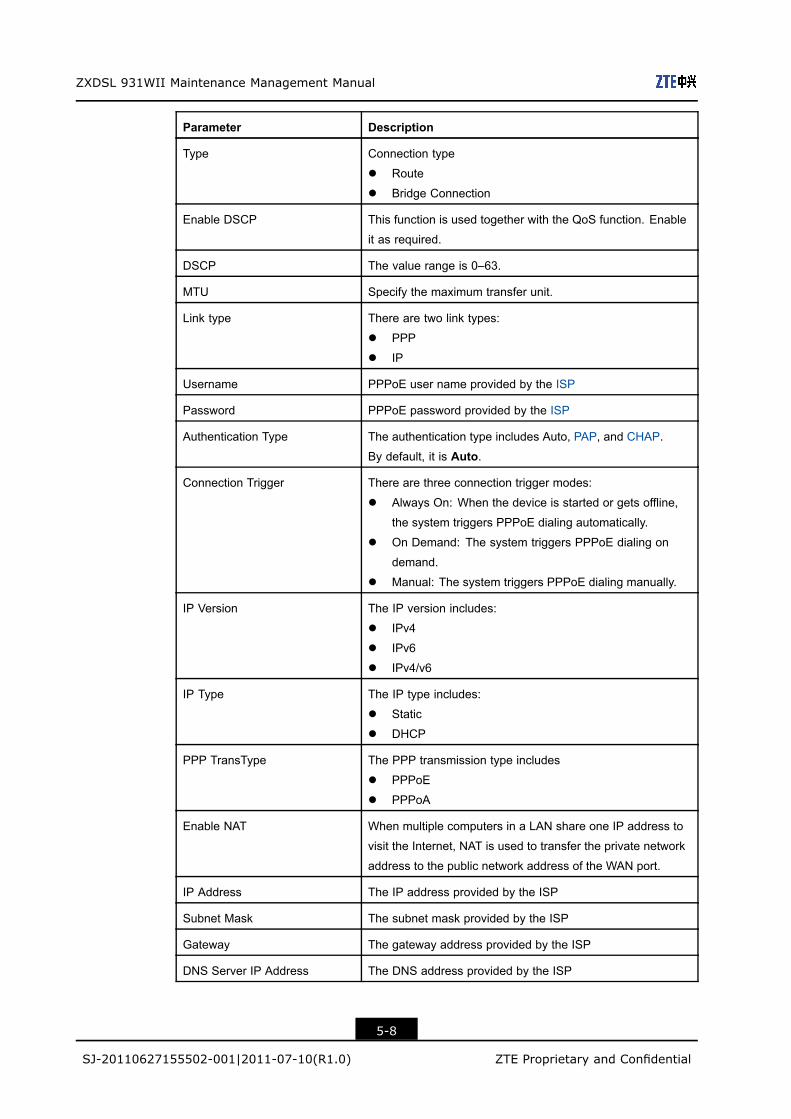
Table 5-3 describes the parameters of ADSL WAN connection page.
Table 5-3 ADSL WAN Connection Parameter
Parameter Description
Connection name The default is Create WAN Connection.Before creating new connection, make sure the Create WANConnection option is selected.
New Connection Name Specify the name of the new WAN connection.
VPI/VCI Channel number of the ATM cell
Each ADSL port has eight PVC, which can be configured with
different VPIs and VCIs. This should be consistent with the
port configuration on the NE.
New VPI/VCI Create a VPI/VCI.
Encapsulation Type Encapsulation type of the IP packets
By default, it is LLC.
Service Type Define the bit rate.
Enable VLAN Enable the VLAN.
VLAN ID Specify the VLAN ID.
802.1p After the VLAN option is selected, you can specify the 802.1p
value to modify the service priority.
The service priority range: 0–7
5-7
SJ-20110627155502-001|2011-07-10(R1.0) ZTE Proprietary and Confidential
ZXDSL 931WII Maintenance Management Manual
Parameter Description
Type Connection type
l Route
l Bridge Connection
Enable DSCP This function is used together with the QoS function. Enable
it as required.
DSCP The value range is 0–63.
MTU Specify the maximum transfer unit.
Link type There are two link types:
l PPP
l IP
Username PPPoE user name provided by the ISP
Password PPPoE password provided by the ISP
Authentication Type The authentication type includes Auto, PAP, and CHAP.
By default, it is Auto.
Connection Trigger There are three connection trigger modes:
l Always On: When the device is started or gets offline,
the system triggers PPPoE dialing automatically.
l On Demand: The system triggers PPPoE dialing on
demand.
l Manual: The system triggers PPPoE dialing manually.
IP Version The IP version includes:
l IPv4
l IPv6
l IPv4/v6
IP Type The IP type includes:
l Static
l DHCP
PPP TransType The PPP transmission type includes
l PPPoE
l PPPoA
Enable NAT When multiple computers in a LAN share one IP address to
visit the Internet, NAT is used to transfer the private network
address to the public network address of the WAN port.
IP Address The IP address provided by the ISP
Subnet Mask The subnet mask provided by the ISP
Gateway The gateway address provided by the ISP
DNS Server IP Address The DNS address provided by the ISP
5-8
SJ-20110627155502-001|2011-07-10(R1.0) ZTE Proprietary and Confidential

Chapter 5 Network
2. Specify the WAN connection parameters as required. After the configuration, clickCreate.
– End of Steps –
Result
The newly-created WAN connection is displayed in the Connection Name drop-down list.
5.1.4 Port Binding
Short Description
Perform this procedure to configure port binding.
Context
Port binding is to bind the LAN-side port with the WAN connection.
Steps
1. On the menu bar, click Network >WAN > Port Binding to open the port binding page,as shown in Figure 5-4.
Figure 5-4 Port Binding
2. Select a WAN connection type from the WAN Connection drop-down list, and selectthe LAN port that you need to bind.
3. Click Submit.
– End of Steps –
5-9
SJ-20110627155502-001|2011-07-10(R1.0) ZTE Proprietary and Confidential
ZXDSL 931WII Maintenance Management Manual
ResultPort binding is configured.
5.1.5 DSL Modulation
Short Description
Perform this procedure to configure DSL modulation type.
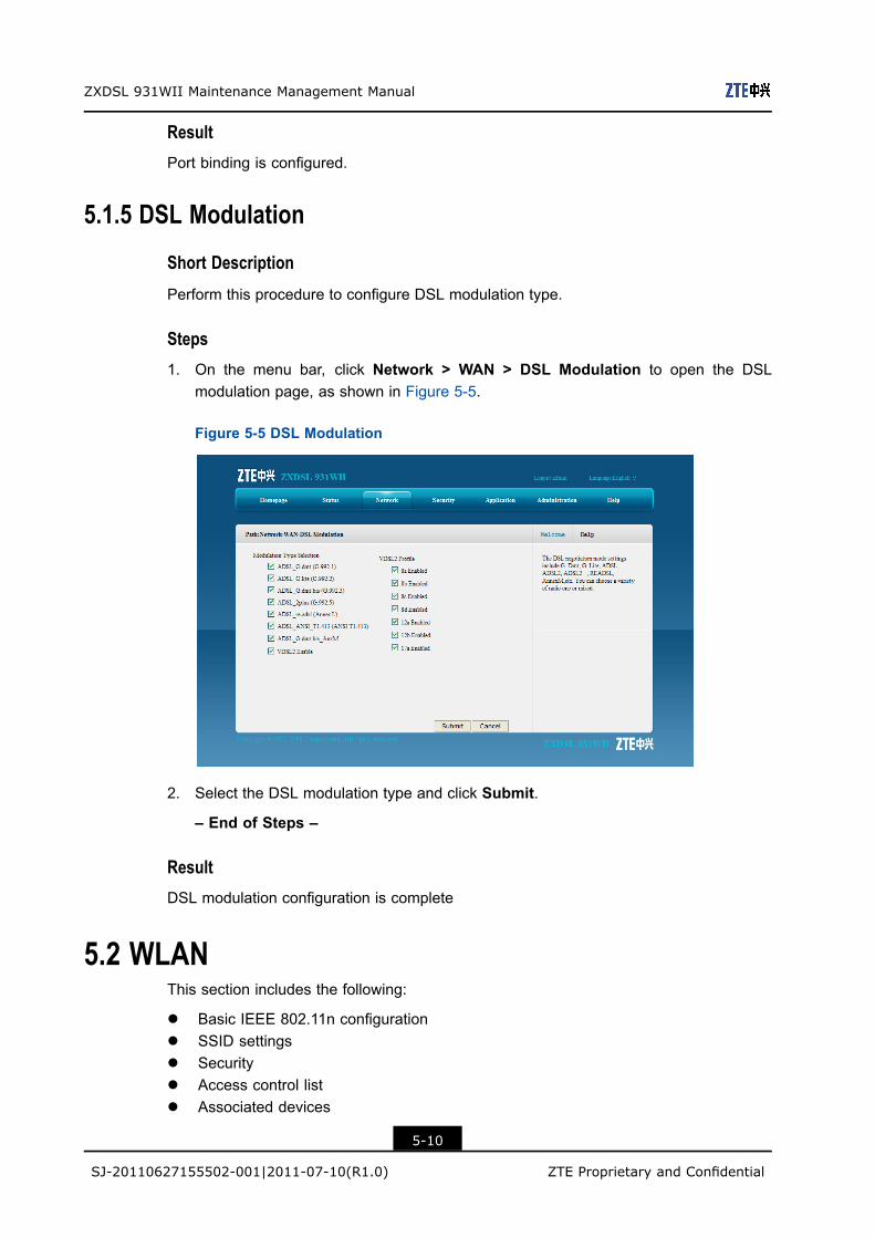
Steps1. On the menu bar, click Network > WAN > DSL Modulation to open the DSL
modulation page, as shown in Figure 5-5.
Figure 5-5 DSL Modulation
2. Select the DSL modulation type and click Submit.
– End of Steps –
ResultDSL modulation configuration is complete
5.2 WLANThis section includes the following:
l Basic IEEE 802.11n configurationl SSID settingsl Securityl Access control listl Associated devices
5-10
SJ-20110627155502-001|2011-07-10(R1.0) ZTE Proprietary and Confidential

Chapter 5 Network
5.2.1 Basic IEEE 802.11n Configuration
Short Description
Perform this procedure to configure the basic IEEE 802.11n parameters.
Context
The WLAN basic configuration includes the following modes:
l IEEE 802.11b Onlyl IEEE 802.11g Onlyl IEEE 802.11n Onlyl Mixed(802.11b+802.11g)l Mixed(802.11b+802.11g+802.11n)
Steps
1. On the menu bar, click Network > WLAN > Basic(11n) to open the basic(11n) page,as shown in Figure 5-6.
Figure 5-6 Basic(11n)
Table 5-4 describes the parameters of IEEE 802.11n configuration.
Table 5-4 IEEE 802.11n Configuration Parameter
Parameter Description
Wireless RF Mode Select Enable to enable the wireless RF function.
Enable isolation Select this option and the wireless clients will not be able to
visit each other.
Mode Select the wireless RF transmission mode.
5-11
SJ-20110627155502-001|2011-07-10(R1.0) ZTE Proprietary and Confidential

ZXDSL 931WII Maintenance Management Manual
Parameter Description
Country/Region Select the country or region.
Band Width You can select 20Mhz or 40Mhz.
Channel The default is Auto.
Beacon Interval Time interval for the wireless device to broadcast the SSID
information.
Keep the default value.
Transmitting Power Select the transmitting power as required.
RTS Threshold Specify the request to send threshold for a packet. When a
packet exceeds this value, the device sends the RTS value to
the destination point for negotiation. The default is 2347.
DTIM Interval The value ranges from 1 to 255 ms.
The default value is 1.
Fragment Threshold When a packet exceeds the fragment threshold, it is divided
into multiple packets. Excessive packet fragments may affect
the network performance, so the fragment threshold should not
be set too big.
It is recommended to set the threshold to an even value. An
odd value is reduced by one to be an even value. The default
is 2346.
2. Select Enabled from the Wireless RF Mode drop-down list to enable the wirelesstransmission function, and then select the transmission mode. For example, selectIEEE 802.11n Only from the Mode drop-down list, and specify the other parametersaccording the request.
3. After the configuration, click Submit.
ResultThe IEEE 802.11n parameters are configured.
5.2.2 SSID Settings
Short Description
Perform this procedure to configure the SSID settings.
ContextThe ZXDSL 931WII can be specified with four SSIDs and each SSID supports up to 32subscribers.
5-12
SJ-20110627155502-001|2011-07-10(R1.0) ZTE Proprietary and Confidential
Chapter 5 Network
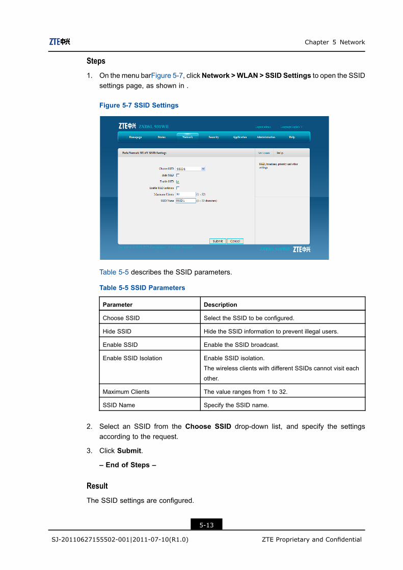
Steps
1. On the menu barFigure 5-7, clickNetwork >WLAN > SSID Settings to open the SSIDsettings page, as shown in .
Figure 5-7 SSID Settings
Table 5-5 describes the SSID parameters.
Table 5-5 SSID Parameters
Parameter Description
Choose SSID Select the SSID to be configured.
Hide SSID Hide the SSID information to prevent illegal users.
Enable SSID Enable the SSID broadcast.
Enable SSID Isolation Enable SSID isolation.
The wireless clients with different SSIDs cannot visit each
other.
Maximum Clients The value ranges from 1 to 32.
SSID Name Specify the SSID name.
2. Select an SSID from the Choose SSID drop-down list, and specify the settingsaccording to the request.
3. Click Submit.
– End of Steps –
Result
The SSID settings are configured.
5-13
SJ-20110627155502-001|2011-07-10(R1.0) ZTE Proprietary and Confidential

ZXDSL 931WII Maintenance Management Manual
5.2.3 Security
Short Description
Perform this procedure to configure the WLAN security.
ContextThe ZXDSL 931WII provides the following access authentication modes:
l Open System
Authentication is not needed. Any client with a wireless network card can connect tothe wireless access point.
l Shared Key
This mode provides WEP encryption.
l WPA-PSK
WPA-PSK is a version of WPA. It uses the pre-shared key. WPA-PSK is similar withWEP but it is securer. The data is encrypted before transmission.
l WPA2-PSK
It is the second version of WPA-PSK.
l WPA/WPA2-PSK
It is a hybrid authentication mode.
Steps1. On the menu bar, click Network > WLAN > Security to open the security page.
2. Select one option from the Authentication Type drop-down list, for example, SharedKey, as shown in Figure 5-8.
5-14
SJ-20110627155502-001|2011-07-10(R1.0) ZTE Proprietary and Confidential

Chapter 5 Network
Figure 5-8 Security
Table 5-6 lists the parameters for the Shared Key authentication mode.
Table 5-6 Parameters for the Shared Key Authentication Mode
Parameter Description
Choose SSID Select the SSID for the security authentication.
Authentication Type Select the authentication type.
WEP Encryption It is enabled by default.
WEP Encryption Level The value can be 64bit or 128bit.
WEP Key Index The WEP authentication provides four keys.
WEP key Use 5 ASCII characters or 10 hexadecimal digits to specify the WEP
value for the 64 bit WEP encryption.
Use 13 ASCII characters or 26 hexadecimal digits to specify the
WEP value for the 128 bit WEP encryption.
Table 5-7 lists the parameters for the WPA-PSK or WPA2-PSK authentication mode.
Table 5-7 Parameters for the WPA-PSK or WPA2-PSK Authentication Mode
Parameter Description
WPA Passphrase Range: 8–63 characters
WPA Group Key Update
Interval
Default: 600 seconds
WPA Encryption
Algorithm
There are three options:
l TKIP:Temporal Key Integrity Protocol
l AES: Advanced Encryption Standard
l TKIP+AES: Adaptive encryption algorithm
5-15
SJ-20110627155502-001|2011-07-10(R1.0) ZTE Proprietary and Confidential

ZXDSL 931WII Maintenance Management Manual
3. Specify the parameters according to the request, and then click Submit.
– End of Steps –
Result
The wireless security authentication configuration is completed.
5.2.4 Access Control List
Short Description
Perform this procedure to configure the ACL.
Context
By default, the ACL function for the ZXDSL 931WII is enabled.
Steps
1. On the menu bar, click Network > WLAN > Access Control List to open the accesscontrol list page, as shown in Figure 5-9.
Figure 5-9 Access Control List
Table 5-8 lists the ACL parameters.
Table 5-8 ACL Parameter
Parameter Description
Choose SSID Choose the SSID to configure the ACL.
5-16
SJ-20110627155502-001|2011-07-10(R1.0) ZTE Proprietary and Confidential
Chapter 5 Network
Parameter Description
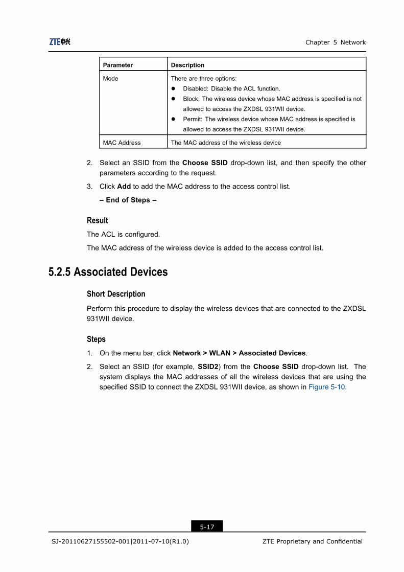
Mode There are three options:
l Disabled: Disable the ACL function.
l Block: The wireless device whose MAC address is specified is not
allowed to access the ZXDSL 931WII device.
l Permit: The wireless device whose MAC address is specified is
allowed to access the ZXDSL 931WII device.
MAC Address The MAC address of the wireless device
2. Select an SSID from the Choose SSID drop-down list, and then specify the otherparameters according to the request.
3. Click Add to add the MAC address to the access control list.
– End of Steps –
ResultThe ACL is configured.
The MAC address of the wireless device is added to the access control list.
5.2.5 Associated Devices
Short Description
Perform this procedure to display the wireless devices that are connected to the ZXDSL931WII device.
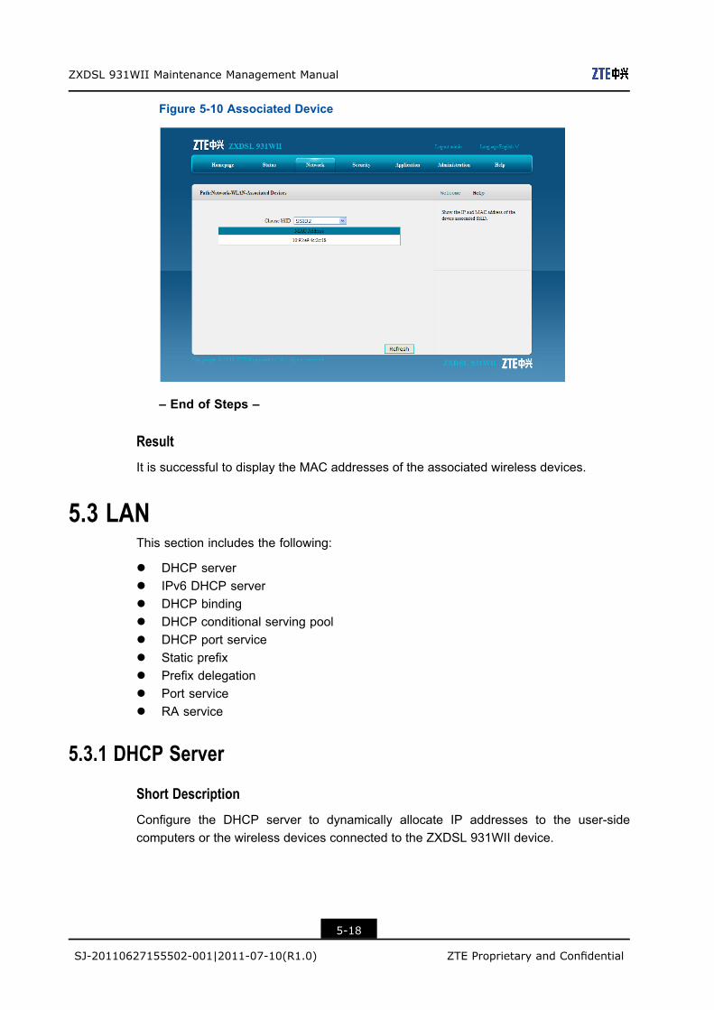
Steps1. On the menu bar, click Network > WLAN > Associated Devices.
2. Select an SSID (for example, SSID2) from the Choose SSID drop-down list. Thesystem displays the MAC addresses of all the wireless devices that are using thespecified SSID to connect the ZXDSL 931WII device, as shown in Figure 5-10.
5-17
SJ-20110627155502-001|2011-07-10(R1.0) ZTE Proprietary and Confidential
ZXDSL 931WII Maintenance Management Manual
Figure 5-10 Associated Device
– End of Steps –
Result
It is successful to display the MAC addresses of the associated wireless devices.
5.3 LANThis section includes the following:
l DHCP serverl IPv6 DHCP serverl DHCP bindingl DHCP conditional serving pooll DHCP port servicel Static prefixl Prefix delegationl Port servicel RA service
5.3.1 DHCP Server
Short Description
Configure the DHCP server to dynamically allocate IP addresses to the user-sidecomputers or the wireless devices connected to the ZXDSL 931WII device.
5-18
SJ-20110627155502-001|2011-07-10(R1.0) ZTE Proprietary and Confidential

Chapter 5 Network
Steps1. On the menu bar, click Network > LAN > DHCP Server to open the DHCP server
page.
2. Specified the DHCP server parameters as request, as shown in Figure 5-11.
Figure 5-11 DHCP Server
Table 5-9 lists the DHCP server parameters.
Table 5-9 DHCP Server Parameters
Parameter Description
LAN IP Address IP address of the ZXDSL 931WII device
The device IP address should be in the same network segment
as the DHCP address pool.
Subnet Mask Subnet mask of the device
Enable Secondary IP The secondary IP address of the ZXDSL 931WII device
Subnet Mask The subnet mask of the device when the device is assigned with
a secondary IP address
Enable DHCP Server Select the Enable DHCP Server check box to let the device work
as a DHCP server and assign IP addresses to the client PCs or
wireless devices.
DHCP Start IP Address The start IP address of the DHCP address pool
DHCP End IP Address The end IP address of the DHCP address pool
Assign IspDNS Select this option to let the DNS provided by the ISP to assign IP
addresses to the client PCs or wireless devices.
DNS Server IP Address IP addresses of the DNS server, provided by the ISP
5-19
SJ-20110627155502-001|2011-07-10(R1.0) ZTE Proprietary and Confidential

ZXDSL 931WII Maintenance Management Manual
Parameter Description
Default Gateway It is usually the IP address of the ZXDSL 931WII device by
default
Lease Time The time that the client PCs use the IP addresses assigned by
the DHCP server. After the lease time expires, the private IP
address will be available for assigning to other network devices.
The default is 86400 seconds.
3. Click Submit.
– End of Steps –
ResultThe DHCP server is configured.
5.3.2 IPv6 DHCP Server
Short Description
Perform this procedure to configure the IPv6 DHCP server to dynamically allocate IPv6addresses to the user-side computers or wireless devices that are connected to the ZXDSL931WII device.
Steps1. On the menu bar, click Network > LAN > IPv6 DHCP Server to open the IPv6 DHCP
server page, as shown in Figure 5-12.
Figure 5-12 IPv6 DHCP Server
Table 5-10 describes the IPv6 DHCP server parameters.
5-20
SJ-20110627155502-001|2011-07-10(R1.0) ZTE Proprietary and Confidential
Chapter 5 Network
Table 5-10 IPv6 DHCP Server Parameters
Parameter Description
LAN IP Address IPv6 address of the ZXDSL 931WII device
Default prefix length: 64 bits
Enable DHCP Server Enable the DHCP server.
DNS Refresh Time The time to refresh the IPv6 address on the user side to keep
the address valid
2. Specify the DHCP server parameters according to the request.
3. Click Submit.
– End of Steps –
ResultThe IPv6 DHCP server is configured.
5.3.3 DHCP Binding
Short Description
Perform this procedure to configure DHCP binding.
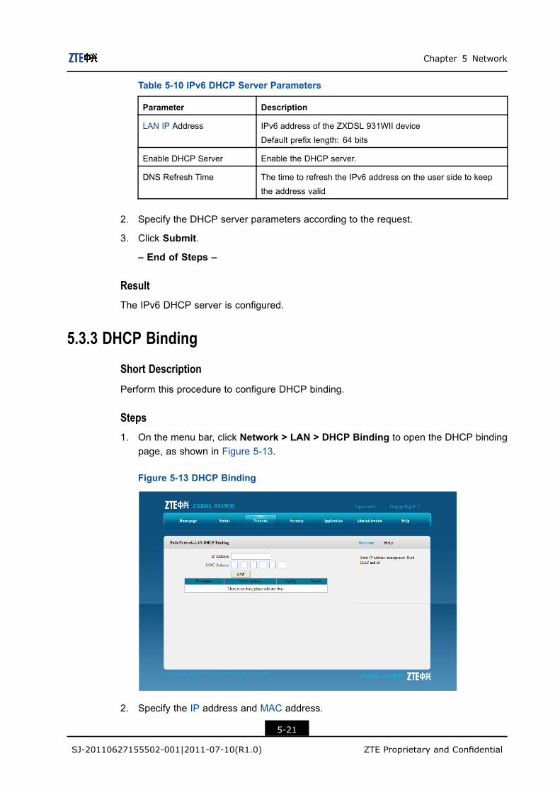
Steps1. On the menu bar, click Network > LAN > DHCP Binding to open the DHCP binding
page, as shown in Figure 5-13.
Figure 5-13 DHCP Binding
2. Specify the IP address and MAC address.
5-21
SJ-20110627155502-001|2011-07-10(R1.0) ZTE Proprietary and Confidential
ZXDSL 931WII Maintenance Management Manual
3. Click Add to bind the IP address with the MAC address.
– End of Steps –
Result
The IP address and MAC address are bound.
5.3.4 DHCP Conditional Serving Pool
Short Description
Perform this procedure to configure the IP address range for one specified interface.
Steps
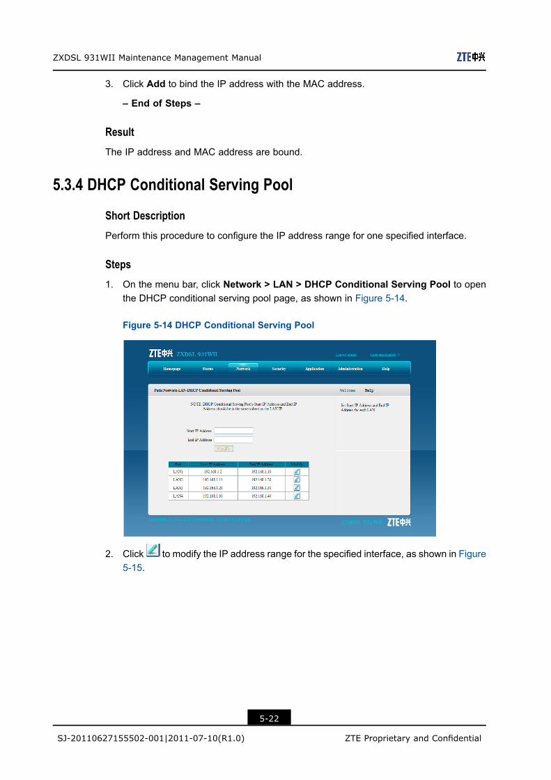
1. On the menu bar, click Network > LAN > DHCP Conditional Serving Pool to openthe DHCP conditional serving pool page, as shown in Figure 5-14.
Figure 5-14 DHCP Conditional Serving Pool
2. Click to modify the IP address range for the specified interface, as shown in Figure5-15.
5-22
SJ-20110627155502-001|2011-07-10(R1.0) ZTE Proprietary and Confidential

Chapter 5 Network
Figure 5-15 Address Range Configuration
Note:
The IP address range of each interface and the IP address of the ZXDSL 931WIIdevice must be in the same network segment.
3. After the modification, click Modify to update the changes
Result
The address range of the specific interface is configured.
5.3.5 DHCP Port Service
Short Description
Perform this procedure to disable the DHCP service for the specified interface when theglobal DHCP function is enabled.
Prerequisites
Before this operation, make sure that the global DHCP service is enabled.
Steps
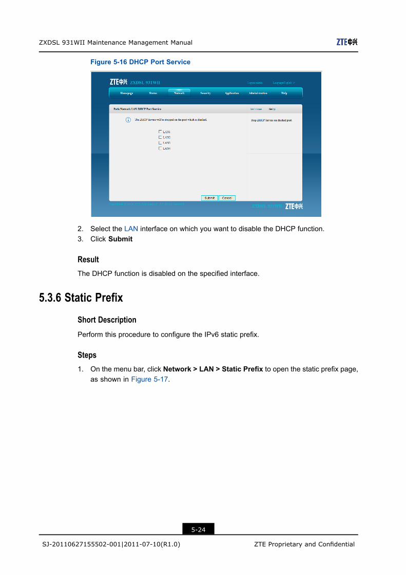
1. On the menu bar, choose Network > LAN > DHCP Port Service to open the DHCPport service page, as shown in Figure 5-16.
5-23
SJ-20110627155502-001|2011-07-10(R1.0) ZTE Proprietary and Confidential
ZXDSL 931WII Maintenance Management Manual
Figure 5-16 DHCP Port Service
2. Select the LAN interface on which you want to disable the DHCP function.3. Click Submit
ResultThe DHCP function is disabled on the specified interface.
5.3.6 Static Prefix
Short Description
Perform this procedure to configure the IPv6 static prefix.
Steps1. On the menu bar, click Network > LAN > Static Prefix to open the static prefix page,
as shown in Figure 5-17.
5-24
SJ-20110627155502-001|2011-07-10(R1.0) ZTE Proprietary and Confidential

Chapter 5 Network
Figure 5-17 Static Prefix
Table 5-11 describers the parameters for IPv6 static prefix.
Table 5-11 Static Prefix Parameters
Parameter Description
Prefix IPv6 address prefix
Prefer Life Time Preferred life time of the prefix
The device on the LAN side refreshes the IPv6 address in the
preferred life time.
Preferred life time is equal to or less than valid life time
Unit: second
Valid Life Time Valid time of the prefix
Delegation Prefix delegation mode:
l RA
l DHCPV6
2. Configure the parameters as request.
3. Click Add.
– End of Steps –
Result
The IPv6 static prefix is configured.
5-25
SJ-20110627155502-001|2011-07-10(R1.0) ZTE Proprietary and Confidential

ZXDSL 931WII Maintenance Management Manual
5.3.7 Prefix Delegation
Short Description
Perform this procedure to configure the IPv6 prefix delegation mode for a specified WANconnection.
Steps
1. On the menu bar, click Network > LAN > Prefix Delegation to open the prefixdelegation page, as shown in Figure 5-18.
Figure 5-18 Prefix Delegation
Table 5-12 describers the parameters of prefix delegation.
Table 5-12 Prefix Delegation Parameters
Parameter Description
WAN Connection The configured WAN connection
Delegation Prefix delegation mode:
l RA
l DHCPV6
2. Configure the parameters according to the request.
– End of Steps –
Result
The IPv6 prefix delegation mode for a specified WAN connection is configured.
5-26
SJ-20110627155502-001|2011-07-10(R1.0) ZTE Proprietary and Confidential

Chapter 5 Network
5.3.8 Port Service
Short Description
Perform this procedure to disable the IPv6 address assignment on the specified interface.
Steps
1. On the menu bar, click Network > LAN > Port Service to open the IPv6 port servicepage, as shown in Figure 5-19.
Figure 5-19 Port Service
2. Select the LAN interface on which you want to disable the IPv6 address assignmentfunction.
3. Click Submit
Result
The IPv6 address assignment is disabled on the specified interface.
5.3.9 RA Service
Short Description
Perform this procedure to configure the RA service.
Steps
1. On the menu bar, click Network > LAN > RA Service to open the RA service page.
2. Configure the parameters, as shown in Figure 5-20.
5-27
SJ-20110627155502-001|2011-07-10(R1.0) ZTE Proprietary and Confidential
ZXDSL 931WII Maintenance Management Manual
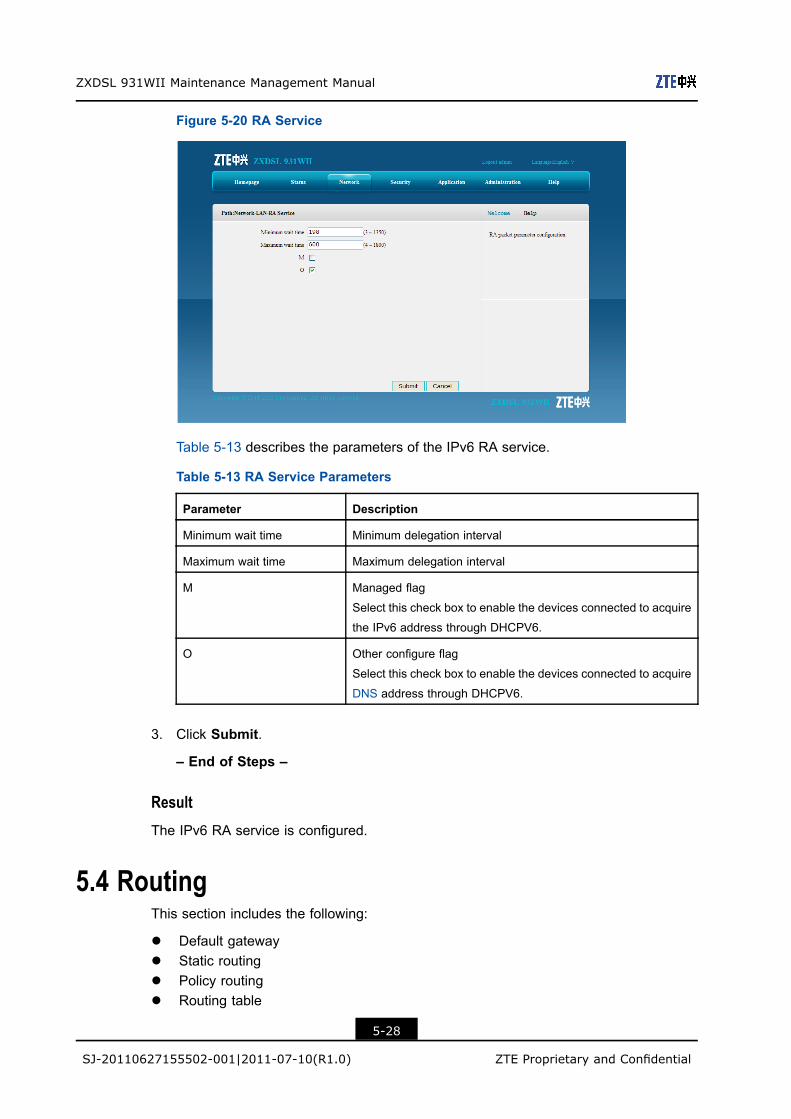
Figure 5-20 RA Service
Table 5-13 describes the parameters of the IPv6 RA service.
Table 5-13 RA Service Parameters
Parameter Description
Minimum wait time Minimum delegation interval
Maximum wait time Maximum delegation interval
M Managed flag
Select this check box to enable the devices connected to acquire
the IPv6 address through DHCPV6.
O Other configure flag
Select this check box to enable the devices connected to acquire
DNS address through DHCPV6.
3. Click Submit.
– End of Steps –
ResultThe IPv6 RA service is configured.
5.4 RoutingThis section includes the following:
l Default gatewayl Static routingl Policy routingl Routing table
5-28
SJ-20110627155502-001|2011-07-10(R1.0) ZTE Proprietary and Confidential

Chapter 5 Network
5.4.1 Default Gateway
Short Description
Perform this procedure to configure the default gateway for the specified WAN connection.
Prerequisites
Before the operation, make sure that:
l The ZXDSL 931WII device uses the router WAN connection mode.l The router WAN connection is created.
Steps
1. On the menu bar, click Network > Routing > Default Gateway to open the defaultgateway page.
2. From the WAN Connection drop-down list, select the desired WAN connection, asshown in Figure 5-21.
Figure 5-21 Default Gateway
Note:
Only the WAN connections that the ZXDSL 931WII device works as a router aredisplayed in the drop-down list.
3. Click Submit.
– End of Steps –
5-29
SJ-20110627155502-001|2011-07-10(R1.0) ZTE Proprietary and Confidential

ZXDSL 931WII Maintenance Management Manual
ResultThe default gateway is configured.
5.4.2 Static Routing
Short Description
Perform this procedure to configure the static routing for the specified WAN connection.
PrerequisitesBefore this operation, make sure that the WAN connection is created.
ContextThe gateway needs to be configured for the static mode interface or IPoA mode interfaceduring static routing configuration.
The gateway does not need to be configured for the PPPoA mode interface or PPPoEmode interface during static routing configuration.
Steps1. On the menu bar, click Network > Routing > Static Routing to open the static routing
page, as shown in Figure 5-22.
Figure 5-22 Static Routing
Table 5-14 describes the parameters for the static routing configuration.
Table 5-14 Static Routing Parameter
Parameter Description
WAN Connection WAN connection for static routing
5-30
SJ-20110627155502-001|2011-07-10(R1.0) ZTE Proprietary and Confidential

Chapter 5 Network
Parameter Description
Network Address Destination network address
Subnet Mask Subnet mask
Gateway Gateway of the network segment which the network interface
belongs to
2. Select one WAN connection from the WAN Connection drop-down list, and thenspecify the parameters according to the request.
3. After the configuration, click Add.
– End of Steps –
5.4.3 Policy Routing
Short Description
Perform this procedure to configure policy routing.
Prerequisites
Before this operation, make sure that the WAN connection settings are complete.
Context
Policy routing is a routing rule. When it is configured, the packets are forwarded accordingto the routing policy. The ZXDSL 931WII device supports packet forwarding according tothe DSCP, source or destination IP address, protocol, source port number, or source MACaddress.
Steps
1. On themenu bar, clickNetwork > Routing > Policy Routing to open the policy routingpage, as shown in Figure 5-23.
5-31
SJ-20110627155502-001|2011-07-10(R1.0) ZTE Proprietary and Confidential

ZXDSL 931WII Maintenance Management Manual
Figure 5-23 Policy Routing
Table 5-15 lists the parameters for policy routing configuration.
Table 5-15 Policy Routing Parameter
Parameter Description
Destination Interface Determined by the carrier
DSCP DSCP vlaue
Source IP Source IP address
Source Mask Source mask of the network segment
Destination IP Destination IP address
Destination Mask Destination mask of the network segment
Protocol Selected as required
Source Port Source port number
Destination Port Destination port number
Source MAC Source MAC address
2. Select an interface from the Destination Interface drop-down list, and specify therouting policy as required.
3. Click Add.
– End of Steps –
Result
Policy routing is configured.
5-32
SJ-20110627155502-001|2011-07-10(R1.0) ZTE Proprietary and Confidential

Chapter 5 Network
5.4.4 Routing Table
ShortDescription
Perform this procedure to display the routing table.
Prerequisites
The routing tables have been created.
Steps
1. On the menu bar, click Network > Routing > Routing Table to open the routing table,as shown in Figure 5-24.
Figure 5-24 Routing Table
Result
The routing table information is displayed.
5.5 IPv6 RoutingThis section includes the following:
l Default gatewayl Static routingl Routing table
5-33
SJ-20110627155502-001|2011-07-10(R1.0) ZTE Proprietary and Confidential

ZXDSL 931WII Maintenance Management Manual
5.5.1 Default Gateway
Short Description
Perform this procedure to configure the default gateway for the IPv6 WAN connections.
Prerequisites
Before the operation, make sure that the IPv6 WAN connection is configured.
Steps
1. On the menu bar, click Network > IPv6_Routing > Default Gateway to open the IPv6default gateway page, as shown in Figure 5-25.
Figure 5-25 IPv6 Routing Default Gateway
2. From the WAN Connection drop-down list, select the WAN connection.
3. Click Submit.
– End of Steps –
Result
The default gateway for the IPv6 routing connections is configured.
5.5.2 Static Routing
Short Description
Perform this procedure to configure IPv6 static routing.
5-34
SJ-20110627155502-001|2011-07-10(R1.0) ZTE Proprietary and Confidential
Chapter 5 Network
Prerequisites
Before the operation, make sure that the IPv6 WAN connection is created.
Steps
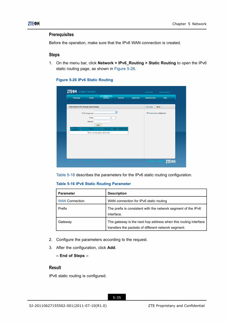
1. On the menu bar, click Network > IPv6_Routing > Static Routing to open the IPv6static routing page, as shown in Figure 5-26.
Figure 5-26 IPv6 Static Routing
Table 5-16 describes the parameters for the IPv6 static routing configuration.
Table 5-16 IPv6 Static Routing Parameter
Parameter Description
WAN Connection WAN connection for IPv6 static routing
Prefix The prefix is consistent with the network segment of the IPv6
interface.
Gateway The gateway is the next hop address when this routing interface
transfers the packets of different network segment.
2. Configure the parameters according to the request.
3. After the configuration, click Add.
– End of Steps –
Result
IPv6 static routing is configured.
5-35
SJ-20110627155502-001|2011-07-10(R1.0) ZTE Proprietary and Confidential

ZXDSL 931WII Maintenance Management Manual
5.5.3 Routing Table
Short Description
Perform this procedure to display the IPv6 routing table.
Prerequisites
The IPv6 routing tables have been created.
Steps
1. On the menu bar, click Network > IPv6_Routing > Routing Table to open the IPv6routing table page, as shown in Figure 5-27.
Figure 5-27 IPv6 Routing Table
– End of Steps –
Result
The IPv6 routing table information is displayed.
5-36
SJ-20110627155502-001|2011-07-10(R1.0) ZTE Proprietary and Confidential
Chapter 6SecurityTable of Contents
Firewall ......................................................................................................................6-1IP Filter ......................................................................................................................6-2MAC Filter ..................................................................................................................6-4Parent Control ............................................................................................................6-6Service Control.........................................................................................................6-10ALG .........................................................................................................................6-12
6.1 FirewallShort Description
Perform this procedure to configure the firewall to prevent malicious attack from theexternal network and enhance device security.
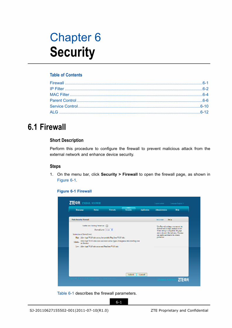
Steps1. On the menu bar, click Security > Firewall to open the firewall page, as shown in
Figure 6-1.
Figure 6-1 Firewall
Table 6-1 describes the firewall parameters.
6-1
SJ-20110627155502-001|2011-07-10(R1.0) ZTE Proprietary and Confidential

ZXDSL 931WII Maintenance Management Manual
Table 6-1 Firewall Parameters
Parameter Description
Enable Anti-Hacking
Protection
Select the check box to enable the firewall settings and prevent the
device from being attacked by the Internet data stream. These attacks
include ping flood, ping to death and syn flood.
Firewall Level l High: Select this option to allow legal WAN-side access but
prohibit PING from the WAN-side.
l Middle: Select this option to allow legal WAN side access and
stop certain types of dangerous data stream from accessing the
device.
l Low: Select this option to allow legal WAN-side access and the
PING from the WAN-side.
2. Configure the firewall parameters according to the request.
3. Click Submit.
– End of Steps –
ResultThe firewall is configured.
6.2 IP FilterShort Description
Perform this procedure to configure the IP filter to permit or deny specific IP addresses toaccess the device.
Steps1. On the menu bar, click Security > IP Filter to open the filter page, as show in Figure
6-2. On this page, you can specify the IP address and port ranges that the datatransmission will be denied or allowed to pass through.
6-2
SJ-20110627155502-001|2011-07-10(R1.0) ZTE Proprietary and Confidential

Chapter 6 Security
Figure 6-2 IP Filter
Table 6-2 lists the IP filter parameters.
Table 6-2 IP Filter Parameter
Parameter Description
Enable Enable the IP filter function.
Protocol Select the protocol that needs to filter packets. By
default, it is TCP.
Name The name of the IP filter setting
The name must be specified.
Start Source IP Address/End Source IP
Address
(Optional) start/end source IP address
Start Destination IP Address/End
Destination IP Address
(Optional) start/end destination IP address
Start Source Port/End Source Port (Optional) start/end source port
Start Destination Port/End Destination
Port
(Optional) start/end destination port
Ingress Specify the data stream direction. The Ingress and
Egress cannot be the same.
l If the Ingress is LAN, the Egress should be theWAN connection. The data stream direction is
upstream.
l If the Ingress is WAN connection, the Egressshould be the LAN. The data stream direction is
downstream.
6-3
SJ-20110627155502-001|2011-07-10(R1.0) ZTE Proprietary and Confidential

ZXDSL 931WII Maintenance Management Manual
Parameter Description
Egress Specify the data stream direction. The Ingress and
Egress cannot be the same.
l If the Egress is LAN, the Ingress should be theWAN connection. The data stream direction is
downstream.
l If the Egress is WAN connection, the Ingressshould be the LAN. The data stream direction is
upstream.
Mode Specify to discard or permit the data packages.
2. Configure the IP filter parameters according to the request.
3. After the configuration, click Add.
– End of Steps –
Result
The IP filter is configured.
Packets with specified IP addresses and ports are denied or allowed to pass.
6.3 MAC FilterShort Description
You can configure MAC filter to permit or deny specific MAC addresses to access thedevice.
Context
MAC filter aims at the user-side LAN, that is, the upstream data flow.
Steps
1. On the menu bar, click Security > MAC Filter to open the MAC filter page, as shownin Figure 6-3. On this page you can specify to discard or permit the data packages byconfiguring the MAC address, protocol and the connection type.
6-4
SJ-20110627155502-001|2011-07-10(R1.0) ZTE Proprietary and Confidential

Chapter 6 Security
Figure 6-3 MAC Filter
Table 6-3 lists the MAC filter parameters.
Table 6-3 MAC Filter Parameter
Parameter Description
Enable Select the check box to enable the MAC filter item.
Mode Specify to permit or discard the data packages.
Type The connection type
The connection type includes Bridge, Route, orBridge+Route.
Protocol Select the protocol that the MAC filter settings will be applied
to.
Source MAC Address/Destina-
tion MAC Address
The MAC address of the data packets.
It cannot be null.
2. Configure the MAC filter parameters according to the request.
3. After the configuration, click Add.
– End of Steps –
Result
MAC filter is configured.
The packets with the specified MAC address are denied or allowed to pass through.
6-5
SJ-20110627155502-001|2011-07-10(R1.0) ZTE Proprietary and Confidential

ZXDSL 931WII Maintenance Management Manual
6.4 Parent ControlThis section includes the following:
l User informationl URL filterl Port filter
6.4.1 User Information
Short Description
Perform this procedure to configure the user information according to the IP address, MACaddress, and time.
Steps
1. On the menu bar, click Security > Parental Control > User Information to open theuser information page, as shown in Figure 6-4.
Figure 6-4 User Information
Table 6-4 describes the user information parameters.
Table 6-4 User Information
Parameter Description
Enable Parental Control Enable the parent control function.
6-6
SJ-20110627155502-001|2011-07-10(R1.0) ZTE Proprietary and Confidential

Chapter 6 Security
Parameter Description
User ID Configure the user information according to the IP address
or MAC address.
If the All user option is selected, all the users that use theZXDSL 931WII device are included.
If
Source IP address The source IP address of the user
Source MAC address The source MAC address of the user
Days Specify the days when the parent control settings are applied.
Time Specify the time when the parent control settings are applied.
Note:
If both MAC address and IP address are configured for the parent control setting, theMAC address setting is of higher priority.
2. Configure the user information according to the request.3. After the configuration, click Add.
Results
The user information of the parent control is configured.
6.4.2 URL Filter
Short Description
You can configure URL filter to permit or deny the LAN users to access the specific URLaddresses.
Prerequisites
The user information of the parent control is configured.
Steps
1. On the menu bar, click Security > URL Filter to open the URL filter page, as shownin Figure 6-5. On this page, you can permit or discard the user to access the specifiedURL addresses.
6-7
SJ-20110627155502-001|2011-07-10(R1.0) ZTE Proprietary and Confidential

ZXDSL 931WII Maintenance Management Manual
Figure 6-5 URL Filter
Table 6-5 describes the URL filter parameters.
Table 6-5 URL Filter Parameter
Parameter Description
User Information Select the user that the URL filter setting is applied to.
Enable Enable the URL filter function.
Mode There are two modes: Discard and Permit.
URL Address The URL address that is allowed to be accessed or denied
2. Select the user and specify the URL information according to the request.
3. After the configuration, click Add.
– End of Steps –
Result
URL filter is configured.
The selected user is permit or denied to access the specified URL address.
6.4.3 Port Filter
Short Description
Perform this procedure to configure the port filter settings for the specified user.
6-8
SJ-20110627155502-001|2011-07-10(R1.0) ZTE Proprietary and Confidential
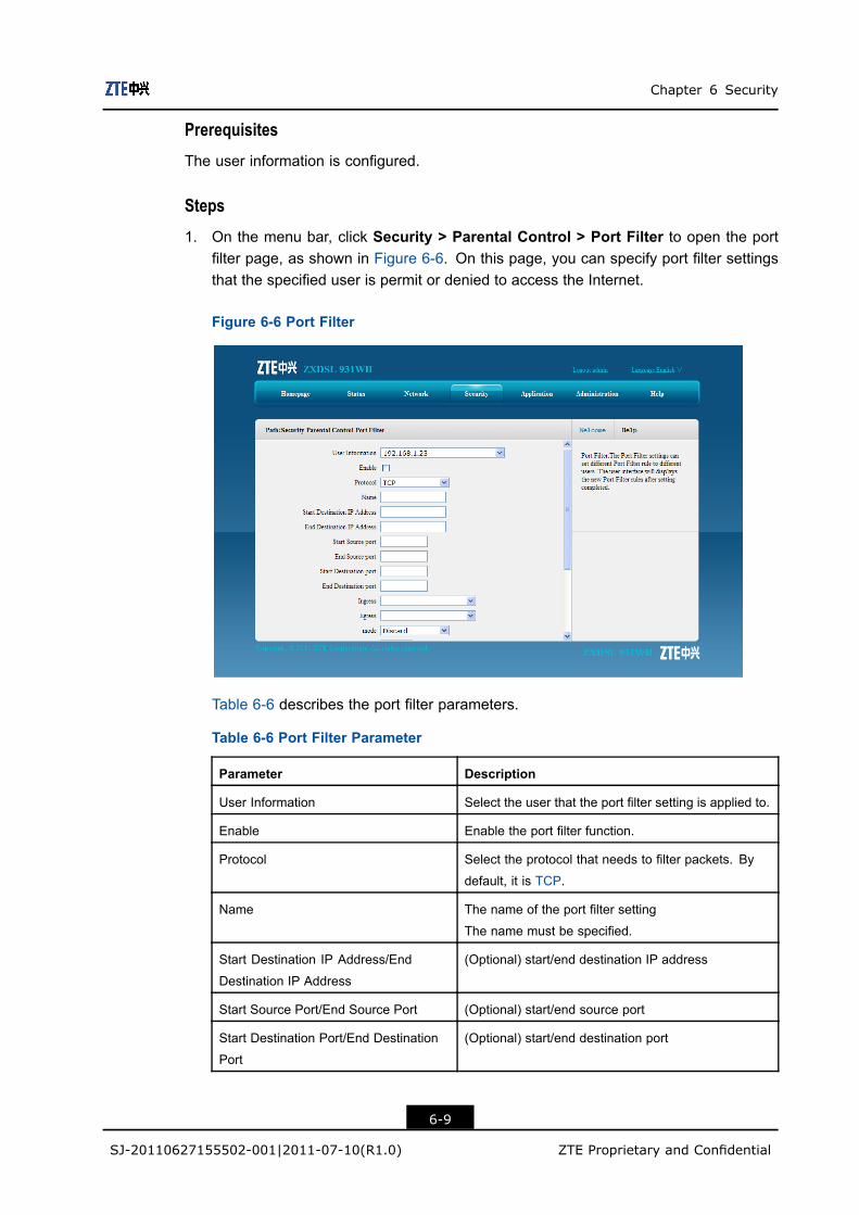
Chapter 6 Security
Prerequisites
The user information is configured.
Steps
1. On the menu bar, click Security > Parental Control > Port Filter to open the portfilter page, as shown in Figure 6-6. On this page, you can specify port filter settingsthat the specified user is permit or denied to access the Internet.
Figure 6-6 Port Filter
Table 6-6 describes the port filter parameters.
Table 6-6 Port Filter Parameter
Parameter Description
User Information Select the user that the port filter setting is applied to.
Enable Enable the port filter function.
Protocol Select the protocol that needs to filter packets. By
default, it is TCP.
Name The name of the port filter setting
The name must be specified.
Start Destination IP Address/End
Destination IP Address
(Optional) start/end destination IP address
Start Source Port/End Source Port (Optional) start/end source port
Start Destination Port/End Destination
Port
(Optional) start/end destination port
6-9
SJ-20110627155502-001|2011-07-10(R1.0) ZTE Proprietary and Confidential
ZXDSL 931WII Maintenance Management Manual
Parameter Description
Ingress Specify the data stream direction. The Ingress and
Egress cannot be the same.
l If the Ingress is LAN, the Egress should be theWAN connection. The data stream direction is
upstream.
l If the Ingress is WAN connection, the Egressshould be the LAN. The data stream direction is
downstream.
Egress Specify the data stream direction. The Ingress and
Egress cannot be the same.
l If the Egress is LAN, the Ingress should be theWAN connection. The data stream direction is
downstream.
l If the Egress is WAN connection, the Ingressshould be the LAN. The data stream direction is
upstream.
Mode There are two modes: Discard and Permit.
2. Configure the port filter parameters according to the request.
3. After the configuration, click Add.
– End of Steps –
Result
The port filter settings for the specified user is complete.
6.5 Service ControlShort Description
Perform this procedure to permit or discard the specified inbound access services byconfiguring the source IP address range and service type.
Steps
1. On the menu bar, click Security > Service Control to open the service control page,as shown in Figure 6-7. On this page, you can permit or discard the specified inboundaccess services by configuring the source IP address range and service type.
6-10
SJ-20110627155502-001|2011-07-10(R1.0) ZTE Proprietary and Confidential

Chapter 6 Security
Figure 6-7 Service Control
Table 6-7 lists the service control parameters.
Table 6-7 Service Control Parameter
Parameter Description
Enable Enable the service control function.
Ingress Specify the data stream inbound direction.
This parameter cannot be null.
Start Source IP Address/End
Source IP Address
IP address segment that needs to be filtered.
When this parameter is null, it refers to all the IP addresses.
Mode The mode can be Discard or Permit.
Service List Specified the service that is permit or denied to access.
2. Configure the service control parameters according to the request.
3. After the configuration, click Add.
– End of Steps –
Result
The service control setting is configured.
The user with specified IP address is permit or denied to access the service that the ZXDSL931WII device provides.
6-11
SJ-20110627155502-001|2011-07-10(R1.0) ZTE Proprietary and Confidential

ZXDSL 931WII Maintenance Management Manual
6.6 ALGShort Description
Perform this procedure to configure the ALG settings.
Context
The ALG functions allows the system to convert the private addresses to the publicaddresses in the packets for the security purpose.
The addresses in the packets are converted based on the following protocols:
l FTPl TFTPl SIPl L2TPl H323l RSTPl PPTPl IPSEC
Steps
1. On the menu bar, click Security > ALG to open the ALG page, as shown in Figure 6-8.
Figure 6-8 ALG
2. Select the ALG services by selecting the corresponding check boxes, and then clickSubmit.
– End of Steps –
6-12
SJ-20110627155502-001|2011-07-10(R1.0) ZTE Proprietary and Confidential

Chapter 7ApplicationTable of Contents
DDNS.........................................................................................................................7-1DMZ Host...................................................................................................................7-3UPnP .........................................................................................................................7-4UPnP Port Mapping....................................................................................................7-6Port Forwarding..........................................................................................................7-6DNS Service ..............................................................................................................7-8QoS .........................................................................................................................7-11SNTP .......................................................................................................................7-14IGMP........................................................................................................................7-15MLD .........................................................................................................................7-17USB Storage ............................................................................................................7-19DMS.........................................................................................................................7-20FTP Application........................................................................................................7-22Dynamic Routing......................................................................................................7-23Port Trigger ..............................................................................................................7-24
7.1 DDNSShort Description
You can configure DDNS to enable the host that has a dynamic IP address to provide thedomain name service.
PrerequisitesBefore the operation, make sure that:
l The inbound connection is enabled.l The domain name has been registered.
ContextDNS is the way in which a URL or domain is converted to an IP address. In manyhome networking environments, the DSL IP address is provided by DHCP and thereforechanges from time to time. Dynamic DNS (DDNS) allows you to have a website such aswww.my-site.com in which the IP address is dynamically assigned
After DDNS is applied, the device that has the dynamic IP address can also provide thedomain name service. For example, when the device obtains an IP address through xDSL
7-1
SJ-20110627155502-001|2011-07-10(R1.0) ZTE Proprietary and Confidential

ZXDSL 931WII Maintenance Management Manual
dial-up or DHCP server dynamic allocation, the device provides the domain name service.If the device IP address changes, it does not affect the subscribers’ access on the domainname.
Steps
1. On the menu bar, click Application > DDNS to open the DDNS page, as shown inFigure 7-1.
Figure 7-1 DDNS
Table 7-1 lists the DDNS parameters.
Table 7-1 DDNS Parameter
Parameter Description
Enable Select this option to enable the DDNS function.
Service Type DDNS service type includes dipc, dyndns, and DtDNS.
Server Server address. If the GNUDIP HTTP is used, the server
address is a URL. By default, it is http://ns.eagleeyes.com.cn/cgi-
bin/gdipupdt.cgi.
Username DDNS server user name.
Password DDNS server password.
WAN Connection WAN connection type.
Domain Domain name corresponding to the user.
It takes effect only when the GNUDIP protocol is used.
2. Configure the DDNS parameters according to the request.
7-2
SJ-20110627155502-001|2011-07-10(R1.0) ZTE Proprietary and Confidential

Chapter 7 Application
3. After the configuration, click Submit.
– End of Steps –
ResultDDNS is configured.
7.2 DMZ HostShort Description
You can configure the DMZ settings to enable the computers at the LAN side to provideservices to the outside.
ContextBy default, all the ports are enabled.
Steps1. On the menu bar, clickApplication > DMZHost to open the DMZ host page, as shown
in .
Figure 7-2 DMZ Host
Table 7-2 lists the DMZ host parameters.
Table 7-2 DMZ Host Parameters.
Parameter Description
Enable Select this option to enable the DMZ host function.
7-3
SJ-20110627155502-001|2011-07-10(R1.0) ZTE Proprietary and Confidential
ZXDSL 931WII Maintenance Management Manual
Parameter Description
WAN Connection The WAN connection that the computer at the LAN side uses to
provide service to the outside
Enable MAC Mapping Enable the MAC mapping function.
DMZ Host IP Address The IP address of the computer that provides services to the outside
DMZ Host MAC Address The MAC address of the computer that provides services to the
outside
2. Configure the DMZ host parameters according to the request.
3. After the configuration, click Submit.
– End of Steps –
Result
The DMZ host is configured.
The computer at the LAN side can provides services to the outside.
7.3 UPnPShort Description
Perform this procedure to configure the UPnP setting.
Context
The UPnP function supports zero configuration, invisible networking, and auto discoveryon the device type.
After the function is configured, the device can dynamically enter a network, get its IPaddress, announce its functions and learn functions of other devices.
Steps
1. On the menu bar, click Application > UPnP to open the UPnP page, as shown inFigure 7-3.
7-4
SJ-20110627155502-001|2011-07-10(R1.0) ZTE Proprietary and Confidential
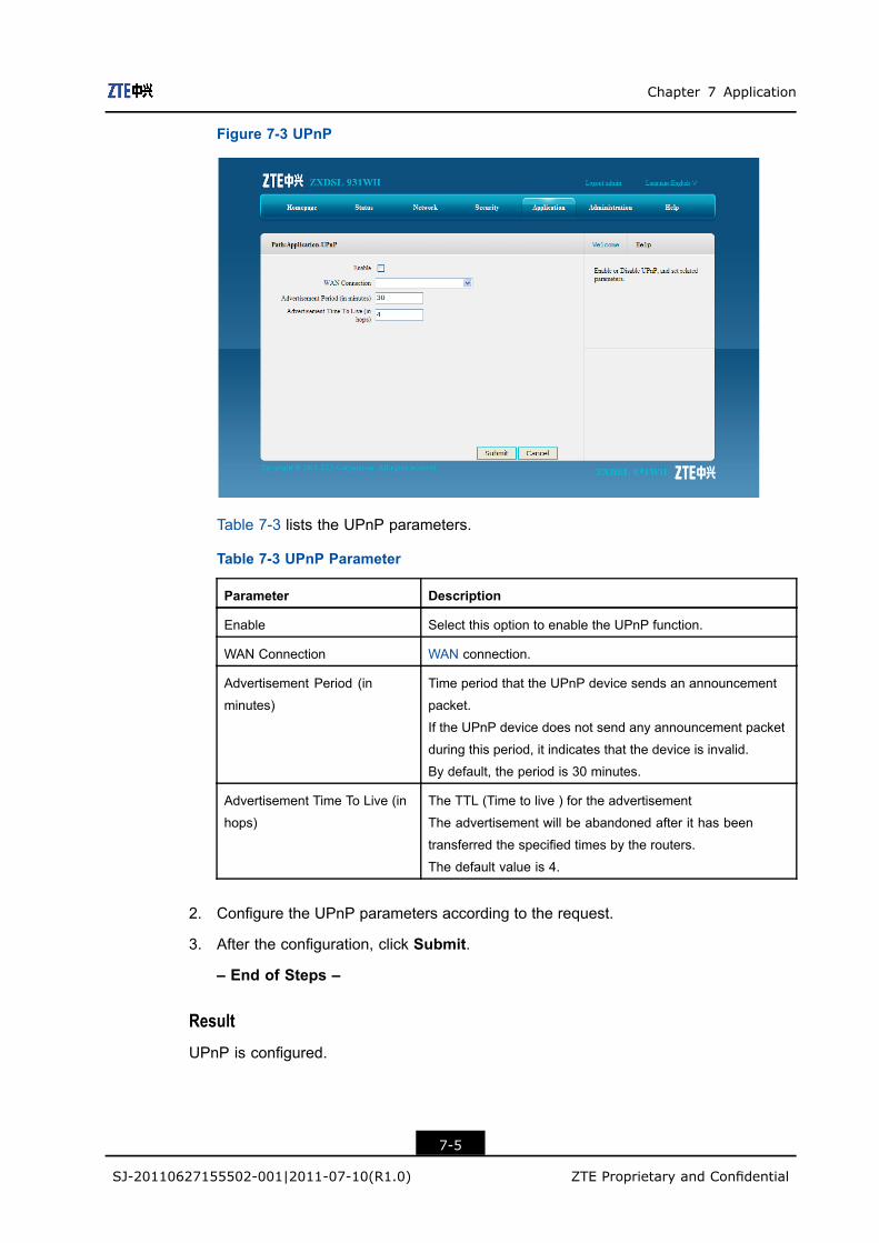
Chapter 7 Application
Figure 7-3 UPnP
Table 7-3 lists the UPnP parameters.
Table 7-3 UPnP Parameter
Parameter Description
Enable Select this option to enable the UPnP function.
WAN Connection WAN connection.
Advertisement Period (in
minutes)
Time period that the UPnP device sends an announcement
packet.
If the UPnP device does not send any announcement packet
during this period, it indicates that the device is invalid.
By default, the period is 30 minutes.
Advertisement Time To Live (in
hops)
The TTL (Time to live ) for the advertisement
The advertisement will be abandoned after it has been
transferred the specified times by the routers.
The default value is 4.
2. Configure the UPnP parameters according to the request.
3. After the configuration, click Submit.
– End of Steps –
Result
UPnP is configured.
7-5
SJ-20110627155502-001|2011-07-10(R1.0) ZTE Proprietary and Confidential

ZXDSL 931WII Maintenance Management Manual
7.4 UPnP Port MappingShort Description
Perform this procedure to display the UPnP port mapping information of the CPE.
Prerequisites
Before this operation, make sure that the UPnP device is connected.
Steps
1. On the menu bar, click Application > UPnP Port Mapping to open the UPnP portmapping page, as shown in Figure 7-4. This page displays the UPnP port mappingrelationship.
Figure 7-4 UPnP Port Mapping
– End of Steps –
Result
UPnP port mapping is displayed.
7.5 Port ForwardingShort Description
You can configure port forwarding so that a computer from the external network can accessthe LAN-side server through the CPE WAN.
7-6
SJ-20110627155502-001|2011-07-10(R1.0) ZTE Proprietary and Confidential

Chapter 7 Application
ContextIf you have local servers for different services and you want to make them publiclyaccessible, you need to specify the port forwarding policy. With NAT applied, it translatesthe internal IP addresses of these servers to a single IP address that is unique on theInternet.
To the Internet users, all virtual servers on your LAN side have the same IP Address. ThisIP Address is allocated by your ISP. This address should be static, rather than dynamic,to make it easier for Internet users to connect to your servers. However, you can useDynamic DNS feature to allow users to connect to your virtual servers by using a URL,instead of an IP address.
Steps1. On the menu bar, click Application > Port Forwarding to open the port forwarding
page, as shown in .
Figure 7-5 Port Forwarding
Table 7-4 lists the port forwarding parameters.
Table 7-4 Port Forwarding Parameter
Parameter Description
Enable Select this option to enable port forwarding function.
Name Virtual host name, which cannot be null
Protocol Protocol name, including TCP, UDP, as well as TCP AND
UDP protocols. The default protocol is TCP.
WAN Host Start IP Address/WAN
Host End IP Address
IP address segment of the WAN-side computers
7-7
SJ-20110627155502-001|2011-07-10(R1.0) ZTE Proprietary and Confidential

ZXDSL 931WII Maintenance Management Manual
Parameter Description
WAN Connection WAN connection that is used to access the virtual host
WAN Start Port/WAN End Port Port number range of the WAN-side computers
Enable MAC Mapping Select this option to map the MAC addresses of the LAN
side computers to a single MAC address.
LAN Host IP Address IP address of the LAN-side host
LAN Host MAC Address MAC address of the LAN-side host
LAN Host Start Port/LAN Host
End Port
Port number range of the LAN-side hosts
2. Configure the port forwarding parameters according to the request.
3. After the configuration, click Add.
– End of Steps –
7.6 DNS ServiceThis section includes the following:
l Domain Namel Hostsl DNS
7.6.1 Domain Name
Short Description
Perform this procedure to configure the domain name to add the device to thecorresponding network domain.
Steps
1. On the menu bar, click Application > DNS Service > Domain Name to open thedomain name page, as shown in Figure 7-6.
7-8
SJ-20110627155502-001|2011-07-10(R1.0) ZTE Proprietary and Confidential

Chapter 7 Application
Figure 7-6 Domain Name
2. Type the domain name in the Domain Name text box.
3. Click Submit.
– End of Steps –
Result
The domain name is configured.
7.6.2 Hosts
Short Description
Perform this procedure to configure the mapping relationship between the user-side hostname and IP address.
Steps
1. On the menu bar, click Application > DNS Service > Hosts to open the hosts page,as shown in Figure 7-7.
7-9
SJ-20110627155502-001|2011-07-10(R1.0) ZTE Proprietary and Confidential

ZXDSL 931WII Maintenance Management Manual
Figure 7-7 Hosts
2. Type the host name in the Host Name text and the IP address in the IP Address textbox.
3. Click Add.
– End of Steps –
7.6.3 DNS
Short Description
Perform this procedure to configure the global DNS parameters.
Steps
1. On the menu bar, click Application > DNS Service > DNS to open the DNS page, asshown in Figure 7-8.
7-10
SJ-20110627155502-001|2011-07-10(R1.0) ZTE Proprietary and Confidential

Chapter 7 Application
Figure 7-8 DNS
2. Type the IP address of the DNS server assigned by the ISP.
3. Click Submit.
– End of Steps –
Result
The global DNS parameters are configured.
7.7 QoSThis section includes the following:
l Basicl Classification
7.7.1 Basic
Short Description
Perform this procedure to enable or disable the QoS function.
Context
SP (Strict Priority) is the simplest queuing mode. It serves the queue with the highest PRIfirst and will not turn to the queue with lower PRI until the first queue is empty. Advantage ofthis approach is that services with higher PRI will always be processed ahead of lower-PRIservices. Nevertheless, lower-PRI services may be thoroughly blocked.
7-11
SJ-20110627155502-001|2011-07-10(R1.0) ZTE Proprietary and Confidential

ZXDSL 931WII Maintenance Management Manual
The WRR (Weighted Round Robin) mode serves all queues and allocates precedence toqueues of higher PRI. In most cases, WRR handles high-PRI services ahead of low-PRIservices. However, it does not necessarily mean that the services of lower PRI will bethoroughly blocked, especially when number of high-PRI services is big.
Steps1. On the menu bar, click Application > QoS > Basic to open the basic page, as shown
in Figure 7-9.
Figure 7-9 Basic
Table 7-5 describes the QoS basic parameters.
Table 7-5 QoS Basic Parameter
Parameter Description
Enable QoS Enable the QoS function.
Enable Committed Access Rate Apply the committed access rate configuration.
Enable Queue Management Apply the queue management configuration.
Schedule Algorithm The schedule algorithm includes SP, DWRR, andSP_DWRR.
Enable DSCP Re-marking Enable the DSCP re-marking function.
Enable 802.1p Re-marking Enable the 802.1p re-marking function.
2. Select Enable QoS to enable the QoS function and then specify other QoS basicparameters.
3. After the configuration, click Submit.
– End of Steps –
7-12
SJ-20110627155502-001|2011-07-10(R1.0) ZTE Proprietary and Confidential

Chapter 7 Application
ResultThe basic QoS parameters are configured.
7.7.2 Classification
Short Description
Perform this procedure to configure the QoS classification rules.
ContextQoS is a network security mechanism that handles network transmission delay andcongestion.
Steps1. On the menu bar, click Application > QoS > Classification to open the classification
page, as shown in Figure 7-10.
Figure 7-10 Classification
Table 7-6 lists the QoS classification parameters.
Table 7-6 QoS Classification Parameters
Parameter Description
Enable Select this option to apply the QoS classification setting.
DevIn Data flow ingress
L2Protocol The layer 2 protocol includes IPv4, IPv6, ARP, and PPPoE
L3Protocol The layer 3 protocol includes TCP, UDP, and ICMP
7-13
SJ-20110627155502-001|2011-07-10(R1.0) ZTE Proprietary and Confidential
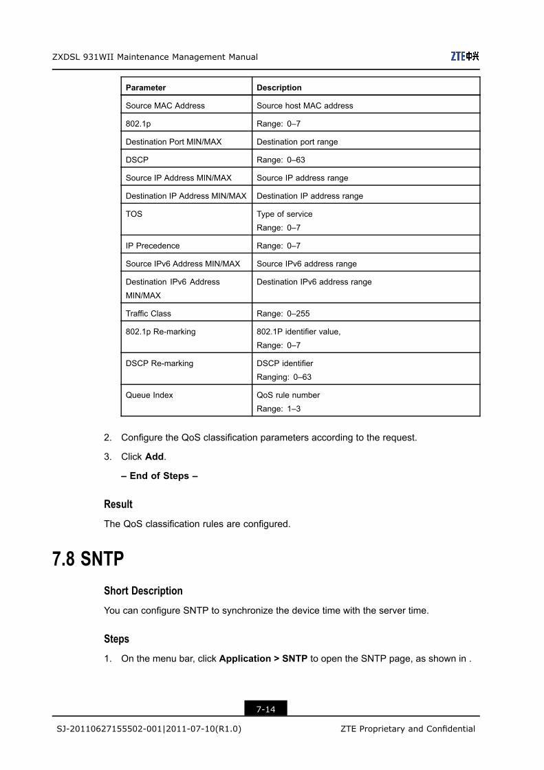
ZXDSL 931WII Maintenance Management Manual
Parameter Description
Source MAC Address Source host MAC address
802.1p Range: 0–7
Destination Port MIN/MAX Destination port range
DSCP Range: 0–63
Source IP Address MIN/MAX Source IP address range
Destination IP Address MIN/MAX Destination IP address range
TOS Type of service
Range: 0–7
IP Precedence Range: 0–7
Source IPv6 Address MIN/MAX Source IPv6 address range
Destination IPv6 Address
MIN/MAX
Destination IPv6 address range
Traffic Class Range: 0–255
802.1p Re-marking 802.1P identifier value,
Range: 0–7
DSCP Re-marking DSCP identifier
Ranging: 0–63
Queue Index QoS rule number
Range: 1–3
2. Configure the QoS classification parameters according to the request.
3. Click Add.
– End of Steps –
Result
The QoS classification rules are configured.
7.8 SNTPShort Description
You can configure SNTP to synchronize the device time with the server time.
Steps
1. On the menu bar, click Application > SNTP to open the SNTP page, as shown in .
7-14
SJ-20110627155502-001|2011-07-10(R1.0) ZTE Proprietary and Confidential

Chapter 7 Application
Figure 7-11 SNTP
Table 7-7 lists the SNTP parameters.
Table 7-7 SNTP Parameters
Parameter Description
Time Zone Time zone
NTP Server Address IP address of the NTP server
Poll Interval Poll interval (Unit: second), interval of time synchronization
Enable Daylight Saving Time Select this option to enable the daylight saving time
function.
DSCP Range: 0–63
2. Configure the SNTP parameters according to the request.
3. After the configuration, click Submit.
– End of Steps –
Result
SNTP is configured.
7.9 IGMPThis section includes the following:
l WAN connectionl Basic configuration
7-15
SJ-20110627155502-001|2011-07-10(R1.0) ZTE Proprietary and Confidential

ZXDSL 931WII Maintenance Management Manual
7.9.1 WAN Connection
Short Description
Perform this procedure to configure the WAN connection for IGMP packets.
Prerequisites
Before this operation, make sure that the WAN connection configuration is complete.
Steps
1. On the menu bar, click Application > IGMP > WAN Connection to open the WANconnection page, as shown in Figure 7-12.
Figure 7-12 WAN Connection
2. Select one WAN connection from theWAN Connection drop-down list, and then clickAdd.
– End of Steps –
Result
The WAN connection for IGMP packets is configured.
7.9.2 Basic Configuration
Short Description
Perform this procedure to enable the basic IGMP function.
7-16
SJ-20110627155502-001|2011-07-10(R1.0) ZTE Proprietary and Confidential

Chapter 7 Application
Steps1. On the menu bar, click Application > IGMP > Basic Configuration to open the basic
configuration page, as shown in Figure 7-13.
Figure 7-13 Basic Configuration
2. Place a checkmark in the IGMP check box to enable the corresponding IGMP function.
3. After the configuration, click Submit.
– End of Steps –
ResultIGMP basic configuration is complete.
7.10 MLDThis section includes the following:
l MLD snoopingl MLD proxy
7.10.1 MLD Snooping
Short Description
Perform this procedure to enable the MLD snooping function.
PrerequisitesBefore the operation, make sure that:
7-17
SJ-20110627155502-001|2011-07-10(R1.0) ZTE Proprietary and Confidential
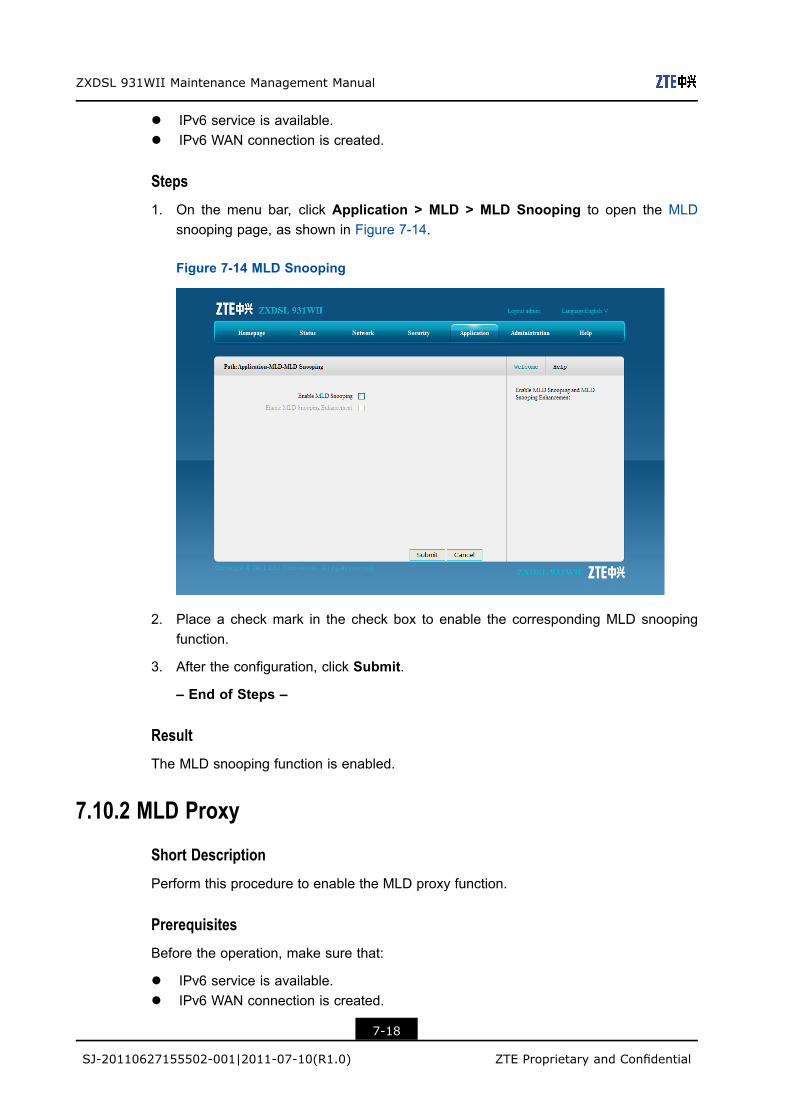
ZXDSL 931WII Maintenance Management Manual
l IPv6 service is available.l IPv6 WAN connection is created.
Steps1. On the menu bar, click Application > MLD > MLD Snooping to open the MLD
snooping page, as shown in Figure 7-14.
Figure 7-14 MLD Snooping
2. Place a check mark in the check box to enable the corresponding MLD snoopingfunction.
3. After the configuration, click Submit.
– End of Steps –
ResultThe MLD snooping function is enabled.
7.10.2 MLD Proxy
Short Description
Perform this procedure to enable the MLD proxy function.
PrerequisitesBefore the operation, make sure that:
l IPv6 service is available.l IPv6 WAN connection is created.
7-18
SJ-20110627155502-001|2011-07-10(R1.0) ZTE Proprietary and Confidential
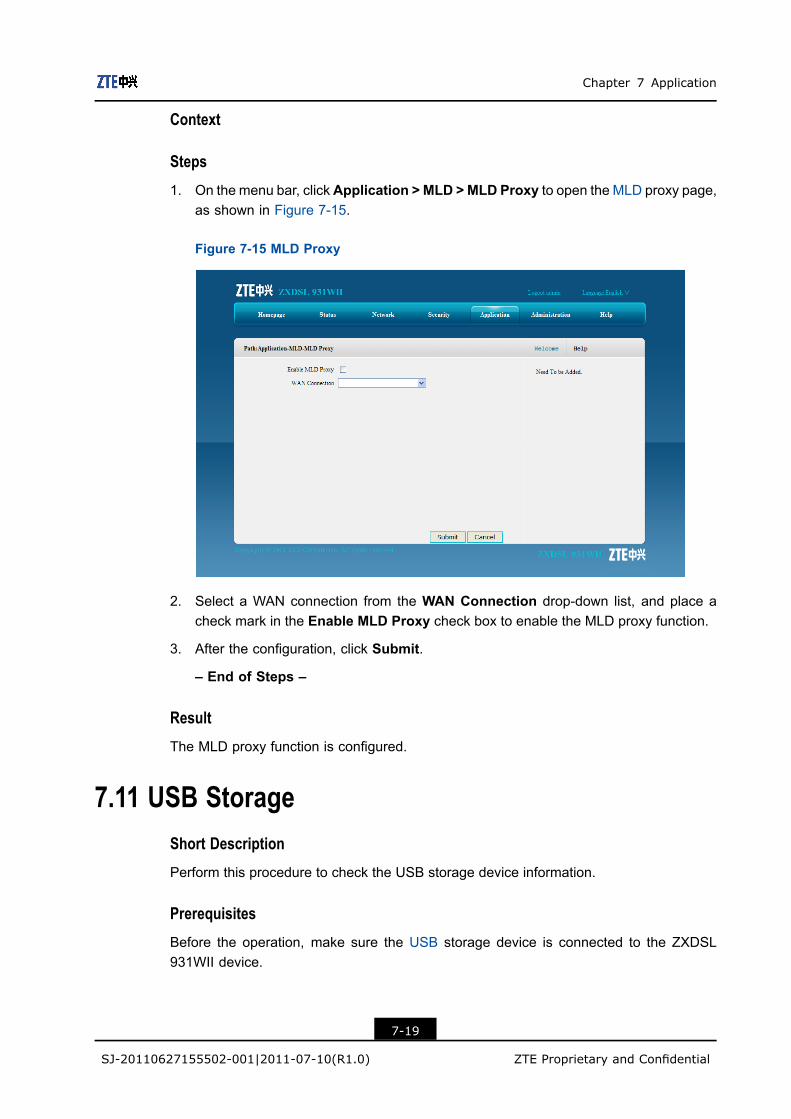
Chapter 7 Application
Context
Steps
1. On the menu bar, clickApplication > MLD >MLD Proxy to open the MLD proxy page,as shown in Figure 7-15.
Figure 7-15 MLD Proxy
2. Select a WAN connection from the WAN Connection drop-down list, and place acheck mark in the Enable MLD Proxy check box to enable the MLD proxy function.
3. After the configuration, click Submit.
– End of Steps –
Result
The MLD proxy function is configured.
7.11 USB StorageShort Description
Perform this procedure to check the USB storage device information.
Prerequisites
Before the operation, make sure the USB storage device is connected to the ZXDSL931WII device.
7-19
SJ-20110627155502-001|2011-07-10(R1.0) ZTE Proprietary and Confidential

ZXDSL 931WII Maintenance Management Manual
Context
The FTP protocol is used to manage the USB storage device.
The default directory to access the USB storage device is /mnt.
Steps
1. On the menu bar, click Application > USB Storage to open the USB storage page,which displays the information of the attached USB storage device, as shown in Figure7-16.
Figure 7-16 USB Storage
– End of Steps –
Result
The information of the attached USB storage device is displayed.
7.12 DMSShort Description
Perform this procedure to configure the DMS settings.
Prerequisites
Before the operation, make sure that:
l The UPnP function is enabled.l The USB device is connected to the device.
7-20
SJ-20110627155502-001|2011-07-10(R1.0) ZTE Proprietary and Confidential

Chapter 7 Application
ContextDMS is a multimedia server defined in DLNA protocol, which uses UPnP protocol to searchand categorize the local media files or photos, and provide VOD services for the DMP.
If the DMS function in enabled on the ZXDSL 931WII device, any client that supports UPnPfunction can use the specified DMP (for example, windows media player) to watch themedia files or photos stored in the USB storage device.
The version of the windows media player used for DMS function must be 11 or later, or theOS must be vista or Win 7. To enable the DMP function in OS of earlier version, specialtools, such as Intel(R) Tool for UPnP(TM) Technology or Twonky Media Manager must beinstalled.
Steps1. On the menu bar, click Application > DMS to open the DMS page, as shown in Figure
7-17.
Figure 7-17 DMS
2. Enable the DMS function, and specify the place to store the media files.
Note:
By default, the media source is /mnt, that is the root directory of the USB device. Youcan change the root directory to other directory of the USB storage device.
3. After the configuration, click Submit.
– End of Steps –
7-21
SJ-20110627155502-001|2011-07-10(R1.0) ZTE Proprietary and Confidential
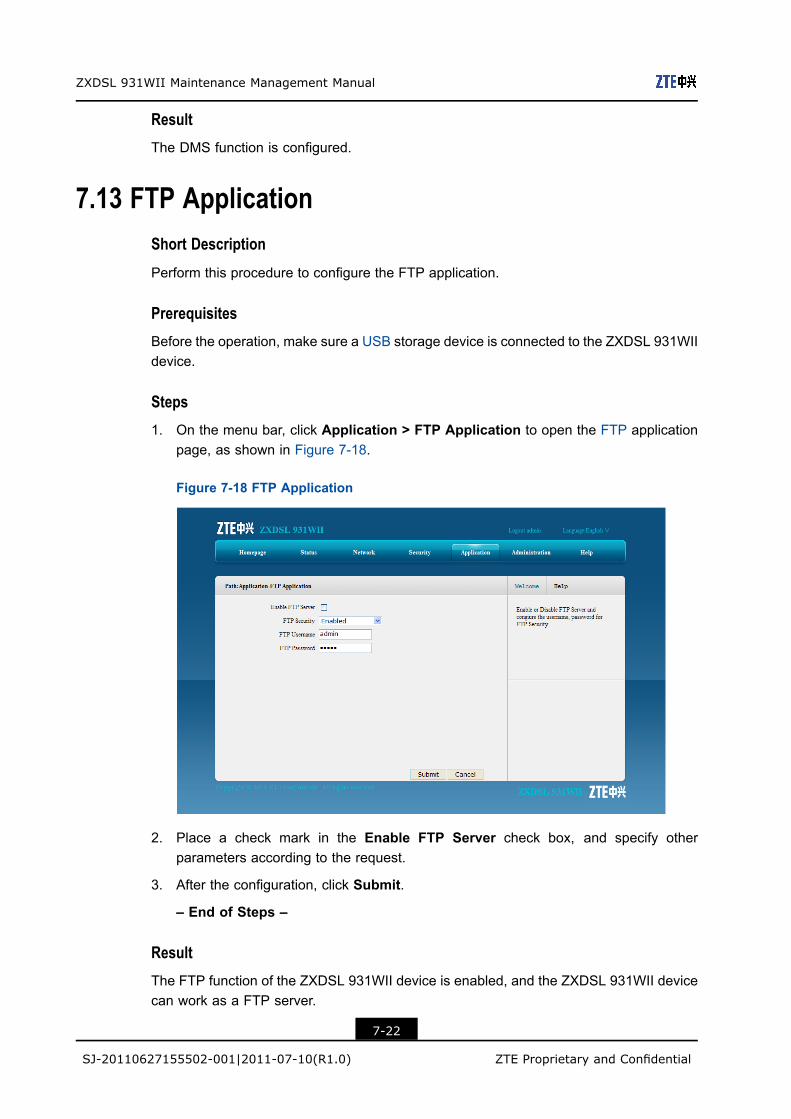
ZXDSL 931WII Maintenance Management Manual
ResultThe DMS function is configured.
7.13 FTP ApplicationShort Description
Perform this procedure to configure the FTP application.
PrerequisitesBefore the operation, make sure a USB storage device is connected to the ZXDSL 931WIIdevice.
Steps1. On the menu bar, click Application > FTP Application to open the FTP application
page, as shown in Figure 7-18.
Figure 7-18 FTP Application
2. Place a check mark in the Enable FTP Server check box, and specify otherparameters according to the request.
3. After the configuration, click Submit.
– End of Steps –
ResultThe FTP function of the ZXDSL 931WII device is enabled, and the ZXDSL 931WII devicecan work as a FTP server.
7-22
SJ-20110627155502-001|2011-07-10(R1.0) ZTE Proprietary and Confidential

Chapter 7 Application
7.14 Dynamic RoutingShort Description
You can enable the RIP dynamic routing function so that the system implements layer-3data forwarding.
Context
RIP is a dynamic routing protocol based on the V-D algorithm. It exchanges the routinginformation through the UDP data packets. RIP has its own routing algorithm. It is adaptiveto the network topology changes, has higher system requirements than static routing, andoccupies certain network resources.
Steps
1. On the menu bar, click Application > Dynamic Routing to open the dynamic routingpage, as shown in Figure 7-19.
Figure 7-19 Dynamic Routing
Table 7-8 lists the dynamic routing parameters.
Table 7-8 Dynamic Routing Parameters
Parameter Description
Enable RIP Enable the RIP function.
Version The options include RIP v1, RIP v2, and RIP v1 Compatible.
2. Configure the dynamic routing parameters according to the request.
7-23
SJ-20110627155502-001|2011-07-10(R1.0) ZTE Proprietary and Confidential

ZXDSL 931WII Maintenance Management Manual
3. Click Submit.
– End of Steps –
Result
Dynamic routing is configured.
7.15 Port TriggerShort Description
Perform this procedure to configure the port triggering function.
Context
When one port is configured to be the triggering port, if one application uses that triggeringport to setup a connection to the outside, the ZXDSL 931WII device will forward the outsideconnection to the internal forwarding port.
The port triggering is used to protect the ports. The system will not open these ports unlessthese ports are triggered.
Steps
1. On the menu bar, click Application > Port Trigger to open the port trigger page, asshown in Figure 7-20.
Figure 7-20 Port Trigger
Table 7-9 lists the port trigger parameters.
7-24
SJ-20110627155502-001|2011-07-10(R1.0) ZTE Proprietary and Confidential

Chapter 7 Application
Table 7-9 Port Trigger Parameters
Parameter Description
Enable Port Triggering Enable port triggering function.
Application Name of the port triggering item
Triggering IP Address IP address of the computer in the LAN side
Service Type The service type of the application, including TCP, UDP, and TCPAND UDP.The default service type is TCP.
Triggering Port The port that the application uses
Connection Type The connection type that is used to connect the outside, including
TCP, UDP, and TCP AND UDP.The default service type is TCP.
WAN Start Port/WAN End
Port
Specify the port range of the device protocol that the triggering port
maps, that is, the layer-4 port number of the packets.
Once the device accesses the triggering port, the service between
the start port and end port will be enabled.
The Start Port and End Port must be specified and meet the
following conditions.
l The end port number is larger than the start port number.
l The difference between the end port number and the start port
number is less than nine
Timeout The time when no traffic occurs
2. Configure the port trigger parameters according to the request.
3. Click Add.
– End of Steps –
Result
Port triggering is configured.
7-25
SJ-20110627155502-001|2011-07-10(R1.0) ZTE Proprietary and Confidential

ZXDSL 931WII Maintenance Management Manual
This page intentionally left blank.
7-26
SJ-20110627155502-001|2011-07-10(R1.0) ZTE Proprietary and Confidential
Chapter 8AdministrationTable of Contents
TR-069 Management .................................................................................................8-1User Management......................................................................................................8-4System Management .................................................................................................8-6Log Management .....................................................................................................8-10Mobile Network Management ...................................................................................8-12Diagnosis .................................................................................................................8-14WAN Type................................................................................................................8-22
8.1 TR-069 ManagementThis section includes the following:
l Configuring TR-069 basic parametersl Managing TR-069 certificate
8.1.1 Configuring TR-069 basic parameters
Short Description
Perform this procedure to configure the TR-069 basic parameters.
Prerequisites
Before the operation, make sure that:
l The WAN connection is configured.l The TR-069 certificate is imported.
Context
TR-069, also known as CPE WAN management protocol, is an NMS protocol carried outby the DSL forum. It manages the terminal devices more effectively.
Steps
1. On the menu bar, clickAdministration > TR-069 Managent > Basic to open the basicpage, as shown in Figure 8-1.
8-1
SJ-20110627155502-001|2011-07-10(R1.0) ZTE Proprietary and Confidential

ZXDSL 931WII Maintenance Management Manual
Figure 8-1 TR-069 Basic Parameter
Table 8-1 lists the TR-069 basic parameters.
Table 8-1 TR-069 Basic Parameter
Parameter Description
WAN Connection WAN connection for the TR-069 service
ACS URL The URL of the automatic configuration server that manages
the device
Default: http://0.0.0.0:9090/web/tr069
Username/Password User name and password for the ZXDSL 931WII device to
log in to the automatic configuration server
Connection Request URL Connection request URL, which is automatically generated
by the system
Enable Request Authentication If this function is enabled, the TR-069 connection will not be
established when the automatic configuration server logs in
to the CPE device unless the automatic configuration server
provides the correct authentication user name and password.
Connection Request
Username/Connection Request
Password
User name and password for the TR-068 connection
authentication that the automatic configuration server
provides when it logs in to the ZXDSL 931WII device
Connection Request Port Specify the connection request port.
Range: 1025–65534
Enable Periodic Inform Enable the periodic inform function.
Periodic Inform Interval Periodic inform interval of the device (unit: second)
Enable Certificate Enable TR-069 certificate
8-2
SJ-20110627155502-001|2011-07-10(R1.0) ZTE Proprietary and Confidential
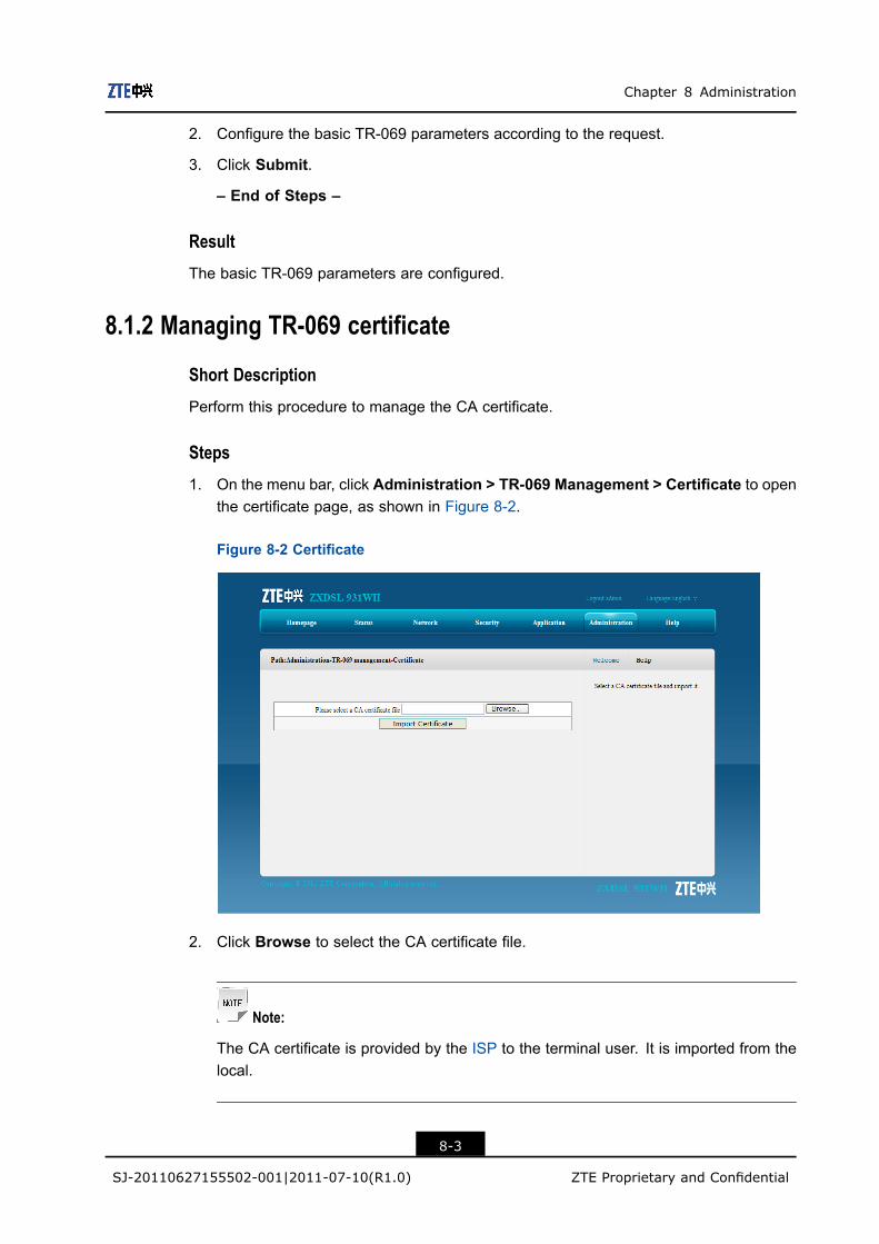
Chapter 8 Administration
2. Configure the basic TR-069 parameters according to the request.
3. Click Submit.
– End of Steps –
Result
The basic TR-069 parameters are configured.
8.1.2 Managing TR-069 certificate
Short Description
Perform this procedure to manage the CA certificate.
Steps
1. On the menu bar, click Administration > TR-069 Management > Certificate to openthe certificate page, as shown in Figure 8-2.
Figure 8-2 Certificate
2. Click Browse to select the CA certificate file.
Note:
The CA certificate is provided by the ISP to the terminal user. It is imported from thelocal.
8-3
SJ-20110627155502-001|2011-07-10(R1.0) ZTE Proprietary and Confidential

ZXDSL 931WII Maintenance Management Manual
3. Click Import Certificate.
– End of Steps –
ResultThe CA certificate is imported.
8.2 User ManagementShort Description
Perform this procedure to manage the user accounts and rights.
ContextTable 8-2 lists the user rights.
Table 8-2 User Rights
Role User Name and Password Right
Administrator User name: admin
Password: admin
The administrator has the privileges to
configure all the parameters in the Web
configuration pages.
User User name: user
Password: user
The common user can only perform the
following operation:
l View the device or network
information
l Software upgrade
l Modify the user name and password
Steps1. On the menu bar, click Administration > User Management to open the user
management page, as shown in Figure 8-3.
8-4
SJ-20110627155502-001|2011-07-10(R1.0) ZTE Proprietary and Confidential

Chapter 8 Administration
Figure 8-3 User Management
Table 8-3 lists the user management parameters.
Table 8-3 User Management Parameters
Parameter Description
User Right You can select Administrator or User to configure the
accounts.
Username The user name for the administrator or user privilege.
The default user name of the administrator privilege is Admin,which cannot be modified.
Old Password The default passwords are as follows:
l Administrator: admin
l User: user
New Password Specify the new password.
Confirm Password Confirm the new password.
2. Configure the user management parameters according to the request.
3. Click Submit.
– End of Steps –
Result
User accounts and rights are configured.
8-5
SJ-20110627155502-001|2011-07-10(R1.0) ZTE Proprietary and Confidential

ZXDSL 931WII Maintenance Management Manual
8.3 System ManagementThis section includes the following:
l System managementl Software upgradel User configuration managementl Default configuration management
8.3.1 System Management
Short Description
Perform this procedure to restart the device or restore the factory default settings.
Steps
1. On the menu bar, click Administration > System Management > SystemManagement to open the system mamagement page, as shown in Figure 8-4.
Figure 8-4 System Management
2. On this page, you can perform the following operations:l Click Reboot to restart the ZXDSL 931WII device.l Click Restore Default to restore the factory default settings.
– End of Steps –
Result
The System management is complete.
8-6
SJ-20110627155502-001|2011-07-10(R1.0) ZTE Proprietary and Confidential

Chapter 8 Administration
8.3.2 Software Upgrade
Short Description
Perform this procedure to upgrade the software.
Prerequisites
Before this operation, make sure that the upgrade file is ready.
Context
Caution!
Generally, the software is upgraded by the ZTE CORPORATION engineers. If the userwants to upgrade the software, contact the local office of ZTE CORPORATION to obtainthe latest software version.
Steps
1. On the menu bar, click Administration > SystemManagement > Software Upgradeto open the software upgrade page, as shown in Figure 8-5.
Figure 8-5 Software Upgrade
2. Click Browse to select the upgrade version file.
3. Click Upgrade.
8-7
SJ-20110627155502-001|2011-07-10(R1.0) ZTE Proprietary and Confidential
ZXDSL 931WII Maintenance Management Manual
Caution!
The system prompts the upgrade progress. During the upgrade process, do not cutoff the power supply. Otherwise, the device may be damaged.
– End of Steps –
Result
After the software is upgraded, the system is automatically restarted and returns to thelogin page.
8.3.3 User Configuration Management
Short Description
Perform this procedure to import and export the user configuration file.
Context
User configuration refers to the customized configuration based on the factory defaults.The user can configure the device settings based on his own requirements. and theconfiguration can be backed up.
To manage the user configuration file, perform the following steps:
Steps
1. On the menu bar, click Administration > System Management > UserConfiguration Management to open the user configuration management page, asshown in Figure 8-6.
8-8
SJ-20110627155502-001|2011-07-10(R1.0) ZTE Proprietary and Confidential

Chapter 8 Administration
Figure 8-6 User Configuration Management
2. Click Backup Configuration to export the user configuration file.l Click Backup Configuration to export the user configuration file.l Click Browse to select the user configuration file, and click Restore
Configuration to restore the device to the user configuration.
Note:
After the user configuration file is imported, the system is restarted.
– End of Steps –
Result
User configuration management is complete.
8.3.4 Default Configuration Management
Short Description
Perform this procedure to import and export the default configuration file.
Steps
1. On the menu bar, click Administration > System Management > DefaultConfiguration Management to opne the default configuration management page,as shown in Figure 8-7.
8-9
SJ-20110627155502-001|2011-07-10(R1.0) ZTE Proprietary and Confidential

ZXDSL 931WII Maintenance Management Manual
Figure 8-7 Default Configuration Management
2. On this page, you can perform the following operations:l Click Backup Configuration to export the default configuration file.l Click Browse to select the default configuration file, and then click Restore
Configuration to restore the ZXDSL 931WII device to the default configuration.
Note:
After the default configuration file is imported, the system is restarted.
– End of Steps –
Result
Default configuration management is complete.
8.4 Log ManagementShort Description
Perform this procedure to manage logs.
Steps
1. On the menu bar, click Administration > Log Management to open the logmanagement page, as shown in Figure 8-8.
8-10
SJ-20110627155502-001|2011-07-10(R1.0) ZTE Proprietary and Confidential

Chapter 8 Administration
Figure 8-8 Log Management
Table 8-4 lists the log management parameters and buttons.
Table 8-4 Log Management Parameters and Buttons
Item Description
Log Enable Select this option to save logs.
Log Level There are eight levels, and they are Emergency, Alert, Critical,Error, Warning, Notice, Informational, and Debug.The options are listed in a descending order with the Emergencythe highest level.
When the log level is configured, only the logs of the configured
log level and higher are saved.
Enable Remote Log Select this option and the device regularly sends the log to the
log server.
Log Server Address IP address of the log server
Refresh Display the latest 20 logs in the text box.
Clear Log Clear the current logs from the text box
Download Log Download the logs to the local disk.
2. Configure the log management parameters, as shown in Figure 8-9.
8-11
SJ-20110627155502-001|2011-07-10(R1.0) ZTE Proprietary and Confidential

ZXDSL 931WII Maintenance Management Manual
Figure 8-9 Log Management Parameter Configuration
3. Click Submit.
– End of Steps –
Result
The logs of the specified level are displayed in the text box.
Manufacturer:ZTE;
ProductClass:ZXDSL 931WII;
SerialNumber:002293012233;
IP:10.63.10.219;
HWVer:96368MVWG;
SWVer:ZXDSL 931WII V3.1_T01;
P0000-00-00T00:36:04 [Notice] Web set successful:
(objname: OBJ_LOG_ID identity: iRet: 0)
8.5 Mobile Network ManagementThis section includes the following:
l PIN managementl Network mode
8-12
SJ-20110627155502-001|2011-07-10(R1.0) ZTE Proprietary and Confidential

Chapter 8 Administration
8.5.1 PIN Management
Short Description
Perform this procedure to perform the PIN management.
PrerequisitesBefore this operation, make sure that:
l 3G network card is ready.l 3G WAN connection is created.
Steps1. On the menu bar, click Administration > Mobile Network Management > PIN
Management to open the PIN management page, as shown in Figure 8-10.
Figure 8-10 PIN Management
2. Configure the PIN management parameters, and then click Submit.
– End of Steps –
ResultThe PIN management is complete.
8.5.2 Network Mode
Short Description
Perform this procedure to select the 3G network mode.
8-13
SJ-20110627155502-001|2011-07-10(R1.0) ZTE Proprietary and Confidential

ZXDSL 931WII Maintenance Management Manual
ContextThe ZXDSL 931WII device supports the WCDMA and GSM network modes.
Steps1. On the menu bar, click Administration > Mobile Network Management > Network
Mode to open the network mode page, as shown in Figure 8-11.
Figure 8-11 Network Mode
2. Select one network mode, and click Submit.
Note:
The ZXDSL 931WII device only supports WCDMA 3G card for the moment. If thenetwork mode is changed, it is necessary to unplug the card and plug it again to makethe change come into effect.
– End of Steps –
ResultThe network mode is selected.
8.6 DiagnosisThis section includes the following:
l Ping Diagnosis
8-14
SJ-20110627155502-001|2011-07-10(R1.0) ZTE Proprietary and Confidential

Chapter 8 Administration
l Trace Route Diagnosisl AT Diagnosisl Mirror Configurationl Ethernet Diagnosisl PPPoE Diagnosisl DNS Diagnosisl IP Diagnosis
8.6.1 Ping Diagnosis
Short Description
Perform this procedure to diagnose the network connectivity.
Steps1. On the menu bar, click Administration > Diagnosis > Ping Diagnosis to open the
ping diagnosis page, as shown in Figure 8-12. On this page, you can select a WANconnection and test the connectivity with the specified address.
Figure 8-12 Ping Diagnosis
2. Type the host IP address or host name in the IP Address or Host Name text box,select the WAN connection from the Egress drop-down list.
3. Click Submit to diagnose the connection, and the system will display the followingdiagnosis results.PING 10.63.10.219 (10.63.10.219): 64 data bytes
Reply from 10.63.10.219: bytes=64 ttl=64 time=0.5ms seq=0
Reply from 10.63.10.219: bytes=64 ttl=64 time=1.2ms seq=1
Reply from 10.63.10.219: bytes=64 ttl=64 time=0.3ms seq=2
8-15
SJ-20110627155502-001|2011-07-10(R1.0) ZTE Proprietary and Confidential

ZXDSL 931WII Maintenance Management Manual
--- 10.63.10.219 ping statistics ---
3 packets transmitted, 3 packets received, 0% packet loss
round-trip min/avg/max = 0.3/0.6/1.2 ms
– End of Steps –
Result
The network connectivity between the ZXDSL 931WII device and specified IP address isdiagnosed.
8.6.2 Trace Route Diagnosis
Short Description
Perform this procedure to display the information of the routes between the ZXDSL 931WIIdevice and the specified address.
Prerequisites
Before the operation, make sure that the WAN connection is created.
Steps
1. On the menu bar, click Administrator > Diagnosis > Trace Route Diagnosis to openthe trace route diagnosis page, as shown in Figure 8-13.
Figure 8-13 Trace Route Diagnosis
8-16
SJ-20110627155502-001|2011-07-10(R1.0) ZTE Proprietary and Confidential

Chapter 8 Administration
2. Type the IP address or host name in the IP Address or Host Name text box, selectone WAN connection, and specify the maximum hops and wait time.
3. After the configuration, click Submit.
– End of Steps –
Result
The information of the routers between the specified IP address and the ZXDSL 931WIIdevice is displayed.
8.6.3 AT Diagnosis
Short Description
Perform this procedure to diagnose the SIM card.
Prerequisites
Before the operation, make sure that the 3G USB wireless card is inserted to the ZXDSL931WIIdevice.
Steps
1. On the menu bar, click Administration > Diagnosis > AT Diagnosis to open the ATDiagnosis page, as shown in Figure 8-14.
Figure 8-14 AT Diagnosis
2. Type AT in the At Command text box, and then click Submit.
8-17
SJ-20110627155502-001|2011-07-10(R1.0) ZTE Proprietary and Confidential

ZXDSL 931WII Maintenance Management Manual
3. The system starts to test whether the 3G USB card works normally. If the messageOK appears, it indicates the 3G card works normally.
– End of Steps –
8.6.4 Mirror Configuration
Short Description
Perform this procedure to perform the mirror configuration.
ContextIf the mirror configuration is performed, the packets at the WAN side will be copied to thespecified LAN interface, and it can be used for the network analysis and troubleshooting.
Steps1. On the menu bar, click Administration > Diagnosis > Mirror Configuration to open
the mirror configuration page, as shown in Figure 8-15.
Figure 8-15 Mirror Configuration
Table 8-5 lists the mirror configuration parameters.
Table 8-5 Mirror Configuration Parameters
Parameter Description
Source Network-side WAN interface
Destination User-side LAN interface
Enable Select this option to enable port mirror.
8-18
SJ-20110627155502-001|2011-07-10(R1.0) ZTE Proprietary and Confidential

Chapter 8 Administration
2. Configure the mirror parameters according to the request.
3. After the configuration, click Add.
– End of Steps –
Result
The port mirror function is configured.
8.6.5 Ethernet Diagnosis
Short Description
Perform this procedure to diagnose the status of the Ethernet port.
Steps
1. On the menu bar, click Administration > Diagnosis > Ethernet Diagnosis to openthe Ethernet diagnosis page, as shown in Figure 8-16.
Figure 8-16 Ethernet Diagnosis
2. Select one Ethernet port and click Diagnose to check the Ethernet connectivity.
– End of Steps –
Result
The status of the specified Ethernet port is checked.
8-19
SJ-20110627155502-001|2011-07-10(R1.0) ZTE Proprietary and Confidential

ZXDSL 931WII Maintenance Management Manual
8.6.6 PPPoE Diagnosis
Short Description
Perform this procedure to diagnose the PPPoE link.
Steps
1. On the menu bar, click Administration > Diagnosis > PPPoE Diagnosis to open thePPPoE diagnosis page, as shown in Figure 8-17.
Figure 8-17 PPPoE Diagnosis
2. Select one PPPoE connection and click Diagnose to check the PPPoE link.
– End of Steps –
Result
The status of the specified PPPoE link is checked.
8.6.7 DNS Diagnosis
Short Description
Perform this procedure to verify whether the existing DNS can translate the specifieddomain name.
Steps
1. On the menu bar, click Administration > Diagnosis > DNS Diagnosis to open theDNS diagnosis page, as shown in Figure 8-18.
8-20
SJ-20110627155502-001|2011-07-10(R1.0) ZTE Proprietary and Confidential

Chapter 8 Administration
Figure 8-18 DNS Diagnosis
2. Type the domain name in the Domain Name text box and click Diagnose to performthe diagnosis.
– End of Steps –
Result
The translation of the domain name by the DNS is verified.
8.6.8 IP Diagnosis
Short Description
Perform this procedure to display the status of the IP connectivity.
Prerequisites
Context
Steps
1. On the menu bar, click Administrator > Diagnosis > IP Diagnosis to open the IPdiagnosis page, as shown in Figure 8-19.
8-21
SJ-20110627155502-001|2011-07-10(R1.0) ZTE Proprietary and Confidential

ZXDSL 931WII Maintenance Management Manual
Figure 8-19 IP Diagnosis
2. Select one WAN connection from the DHCP Connection drop-down list, and thenclick Diagnose to diagnose and display the status of the IP connectivity.
– End of Steps –
ResultThe status of the IP connectivity is displayed.
8.7 WAN TypeShort Description
Perform this procedure to specify the WAN type to be used.
Steps1. On the menu bar, click Administration > WAN Type to open the WAN type page, as
shown in Figure 8-20.
8-22
SJ-20110627155502-001|2011-07-10(R1.0) ZTE Proprietary and Confidential

Chapter 8 Administration
Figure 8-20 WAN Type
2. Select one WAN type from the WAN Type drop-down list.
If DSL(Master)&3GDongle(Backup) or ETH(Master)&3GDongle(Backup) is selected, itis necessary to specify the conditions when to use 3G network.
Table 8-6 lists the related parameters.
Table 8-6 WAN Type Parameter
Parameter Description
Enable 3G Dongle on DSL
line failure
l If the 3G link is created, after the DSL line link is created
successfully, the 3G link will be disconnected in 30 seconds.
In the same way, after the Ethernet link is created successfully,
the 3G link will be disconnected in 30 seconds.
l If the DSL line link or the Ethernet link is created, and 3G link is
ready (WAN connection is configured, but dial-up fails), after the
DSL line link or the Ethernet link is disconnected, the 3G card
will try to dial up in 30 seconds, and the success of the dial-up
depends on the 3G network.
Enable 3G Dongle on PPP
connection Failure
l If the 3G link is created, after the DSL PPP dial–up succeeds
(the link has been created), 3G link will be disconnected in 30
seconds.
In the same way, after the Ethernet PPP dial–up succeeds (the
link has been created), the 3G link will be disconnected in 30
seconds.
l If the DSL dial–up or Ethernet dial–up succeeds, and 3G link is
ready (WAN connection is configured, but dial-up fails), after the
DSL or Ethenet PPP dial–up fails, the 3G card will try to dial up
8-23
SJ-20110627155502-001|2011-07-10(R1.0) ZTE Proprietary and Confidential
ZXDSL 931WII Maintenance Management Manual
Parameter Description
in 30 seconds, and the success of the dial-up depends on the
3G network.
3. After the configuration, click Submit.
Note:
If the WAN type is changed, the ZXDSL 931WII device will automatically recover tothe corresponding WAN type factory configuration.
– End of Steps –
Result
WAN type configuration is complete.
8-24
SJ-20110627155502-001|2011-07-10(R1.0) ZTE Proprietary and Confidential

FiguresFigure 2-1 Interfaces and Buttons ............................................................................. 2-3
Figure 3-1 Entire Connection .................................................................................... 3-1
Figure 3-2 LAN Interface Connection ........................................................................ 3-2
Figure 3-3 Separator Connection .............................................................................. 3-2
Figure 3-4 Power Supply Connection........................................................................ 3-3
Figure 3-5 Pressing the Power Button....................................................................... 3-3
Figure 3-6 Login Page .............................................................................................. 3-5
Figure 3-7 Home Page.............................................................................................. 3-6
Figure 4-1 Device Information................................................................................... 4-1
Figure 4-2 VDSL WAN Connection ........................................................................... 4-2
Figure 4-3 3G Status ................................................................................................ 4-2
Figure 4-4 ADSL WAN Connection ........................................................................... 4-3
Figure 4-5 Mobile Network ........................................................................................ 4-3
Figure 4-6 DSL Link Information ............................................................................... 4-4
Figure 4-7 WLAN...................................................................................................... 4-5
Figure 4-8 Ethernet................................................................................................... 4-5
Figure 4-9 USB......................................................................................................... 4-6
Figure 5-1 VDSL WAN Connection ........................................................................... 5-2
Figure 5-2 3G WAN Connection................................................................................ 5-5
Figure 5-3 ADSL WAN Connection ........................................................................... 5-7
Figure 5-4 Port Binding ............................................................................................. 5-9
Figure 5-5 DSL Modulation ..................................................................................... 5-10
Figure 5-6 Basic(11n).............................................................................................. 5-11
Figure 5-7 SSID Settings ........................................................................................ 5-13
Figure 5-8 Security ................................................................................................. 5-15
Figure 5-9 Access Control List ................................................................................ 5-16
Figure 5-10 Associated Device ............................................................................... 5-18
Figure 5-11 DHCP Server ....................................................................................... 5-19
Figure 5-12 IPv6 DHCP Server .............................................................................. 5-20
Figure 5-13 DHCP Binding...................................................................................... 5-21
Figure 5-14 DHCP Conditional Serving Pool ........................................................... 5-22
Figure 5-15 Address Range Configuration .............................................................. 5-23
I

ZXDSL 931WII Maintenance Management Manual
Figure 5-16 DHCP Port Service .............................................................................. 5-24
Figure 5-17 Static Prefix ......................................................................................... 5-25
Figure 5-18 Prefix Delegation ................................................................................. 5-26
Figure 5-19 Port Service ......................................................................................... 5-27
Figure 5-20 RA Service........................................................................................... 5-28
Figure 5-21 Default Gateway .................................................................................. 5-29
Figure 5-22 Static Routing ...................................................................................... 5-30
Figure 5-23 Policy Routing...................................................................................... 5-32
Figure 5-24 Routing Table....................................................................................... 5-33
Figure 5-25 IPv6 Routing Default Gateway ............................................................. 5-34
Figure 5-26 IPv6 Static Routing .............................................................................. 5-35
Figure 5-27 IPv6 Routing Table............................................................................... 5-36
Figure 6-1 Firewall .................................................................................................... 6-1
Figure 6-2 IP Filter .................................................................................................... 6-3
Figure 6-3 MAC Filter................................................................................................ 6-5
Figure 6-4 User Information ...................................................................................... 6-6
Figure 6-5 URL Filter ................................................................................................ 6-8
Figure 6-6 Port Filter ................................................................................................. 6-9
Figure 6-7 Service Control ...................................................................................... 6-11
Figure 6-8 ALG ....................................................................................................... 6-12
Figure 7-1 DDNS ...................................................................................................... 7-2
Figure 7-2 DMZ Host ................................................................................................ 7-3
Figure 7-3 UPnP....................................................................................................... 7-5
Figure 7-4 UPnP Port Mapping ................................................................................. 7-6
Figure 7-5 Port Forwarding ....................................................................................... 7-7
Figure 7-6 Domain Name.......................................................................................... 7-9
Figure 7-7 Hosts ..................................................................................................... 7-10
Figure 7-8 DNS....................................................................................................... 7-11
Figure 7-9 Basic ..................................................................................................... 7-12
Figure 7-10 Classification ....................................................................................... 7-13
Figure 7-11 SNTP ................................................................................................... 7-15
Figure 7-12 WAN Connection ................................................................................. 7-16
Figure 7-13 Basic Configuration.............................................................................. 7-17
Figure 7-14 MLD Snooping ..................................................................................... 7-18
Figure 7-15 MLD Proxy........................................................................................... 7-19
II

Figures
Figure 7-16 USB Storage........................................................................................ 7-20
Figure 7-17 DMS .................................................................................................... 7-21
Figure 7-18 FTP Application ................................................................................... 7-22
Figure 7-19 Dynamic Routing ................................................................................. 7-23
Figure 7-20 Port Trigger.......................................................................................... 7-24
Figure 8-1 TR-069 Basic Parameter.......................................................................... 8-2
Figure 8-2 Certificate ................................................................................................ 8-3
Figure 8-3 User Management ................................................................................... 8-5
Figure 8-4 System Management ............................................................................... 8-6
Figure 8-5 Software Upgrade.................................................................................... 8-7
Figure 8-6 User Configuration Management ............................................................. 8-9
Figure 8-7 Default Configuration Management........................................................ 8-10
Figure 8-8 Log Management................................................................................... 8-11
Figure 8-9 Log Management Parameter Configuration............................................ 8-12
Figure 8-10 PIN Management................................................................................. 8-13
Figure 8-11 Network Mode...................................................................................... 8-14
Figure 8-12 Ping Diagnosis..................................................................................... 8-15
Figure 8-13 Trace Route Diagnosis......................................................................... 8-16
Figure 8-14 AT Diagnosis........................................................................................ 8-17
Figure 8-15 Mirror Configuration ............................................................................. 8-18
Figure 8-16 Ethernet Diagnosis............................................................................... 8-19
Figure 8-17 PPPoE Diagnosis ................................................................................ 8-20
Figure 8-18 DNS Diagnosis .................................................................................... 8-21
Figure 8-19 IP Diagnosis ........................................................................................ 8-22
Figure 8-20 WAN Type............................................................................................ 8-23
III

Figures
This page intentionally left blank.
TablesTable 2-1 Packing List............................................................................................... 2-1
Table 2-2 Interfaces and Buttons............................................................................... 2-3
Table 2-3 Indicators on the Front Panel..................................................................... 2-3
Table 2-4 Technical Specifications ............................................................................ 2-5
Table 3-1 User Rights ............................................................................................... 3-5
Table 5-1 VDSL WAN Connection Parameter ........................................................... 5-2
Table 5-2 3G WAN Connection Parameter ................................................................ 5-5
Table 5-3 ADSL WAN Connection Parameter ........................................................... 5-7
Table 5-4 IEEE 802.11n Configuration Parameter ................................................... 5-11
Table 5-5 SSID Parameters .................................................................................... 5-13
Table 5-6 Parameters for the Shared Key Authentication Mode .............................. 5-15
Table 5-7 Parameters for the WPA-PSK or WPA2-PSK Authentication Mode ........... 5-15
Table 5-8 ACL Parameter ....................................................................................... 5-16
Table 5-9 DHCP Server Parameters ....................................................................... 5-19
Table 5-10 IPv6 DHCP Server Parameters ............................................................. 5-21
Table 5-11 Static Prefix Parameters ........................................................................ 5-25
Table 5-12 Prefix Delegation Parameters ................................................................ 5-26
Table 5-13 RA Service Parameters ......................................................................... 5-28
Table 5-14 Static Routing Parameter....................................................................... 5-30
Table 5-15 Policy Routing Parameter ...................................................................... 5-32
Table 5-16 IPv6 Static Routing Parameter............................................................... 5-35
Table 6-1 Firewall Parameters .................................................................................. 6-2
Table 6-2 IP Filter Parameter .................................................................................... 6-3
Table 6-3 MAC Filter Parameter................................................................................ 6-5
Table 6-4 User Information........................................................................................ 6-6
Table 6-5 URL Filter Parameter................................................................................. 6-8
Table 6-6 Port Filter Parameter ................................................................................. 6-9
Table 6-7 Service Control Parameter ...................................................................... 6-11
Table 7-1 DDNS Parameter ...................................................................................... 7-2
Table 7-2 DMZ Host Parameters............................................................................... 7-3
Table 7-3 UPnP Parameter ....................................................................................... 7-5
Table 7-4 Port Forwarding Parameter ....................................................................... 7-7
V

ZXDSL 931WII Maintenance Management Manual
Table 7-5 QoS Basic Parameter.............................................................................. 7-12
Table 7-6 QoS Classification Parameters ................................................................ 7-13
Table 7-7 SNTP Parameters ................................................................................... 7-15
Table 7-8 Dynamic Routing Parameters .................................................................. 7-23
Table 7-9 Port Trigger Parameters .......................................................................... 7-25
Table 8-1 TR-069 Basic Parameter ........................................................................... 8-2
Table 8-2 User Rights ............................................................................................... 8-4
Table 8-3 User Management Parameters.................................................................. 8-5
Table 8-4 Log Management Parameters and Buttons.............................................. 8-11
Table 8-5 Mirror Configuration Parameters.............................................................. 8-18
Table 8-6 WAN Type Parameter.............................................................................. 8-23
VI
Index3G Status ............................................. 4-2
AAccess Control List............................. 5-16ADSL WAN Connection........................ 4-3ALG ................................................... 6-12AT Diagnosis ...................................... 8-17
CConfiguring TCP/IP .............................. 3-3
DDefault Gateway................................. 5-29Device Information ............................... 4-1DMZ Host............................................. 7-3DSL Link Information............................ 4-4
EEthernet ............................................... 4-5
HHardware Connection........................... 3-1
IInterfaces ............................................. 2-2IPv6 Default Gateway......................... 5-34IPv6 Routing Table ............................. 5-36IPv6 Static Routing............................. 5-35
LLogging In to the Device....................... 3-4
MMAC Filter ............................................ 6-4Mirror Configuration............................ 8-18Mobile Network .................................... 4-3
PPacking List.......................................... 2-1
Policy Routing .................................... 5-31Product Features.................................. 2-2
RRouting Table ..................................... 5-33
SSafety Precautions ............................... 1-1Security .............................................. 5-14Software Upgrade ................................ 8-7Static Routing..................................... 5-30
TTechnical Specifications ....................... 2-4TR-069................................................. 8-1Trace Route Diagnosis ....................... 8-16
UUPnP ................................................... 7-4UPnP Port Mapping.............................. 7-6USB ..................................................... 4-5User Configuration Management .......... 8-8User Management................................ 8-4
VVDSL Connection................................. 4-2
WWLAN .................................................. 4-4
VII

Index
This page intentionally left blank.
GlossaryAC- Access Control
ACL- Access Control List
ADSL- Asymmetric Digital Subscriber Line
ARP- Address Resolution Protocol
ATM- Asynchronous Transfer Mode
CHAP- Challenge Handshake Authentication Protocol
CPE- Customer Premises Equipment
DC- Direct Current
DDNS- Dynamic Domain Name Server
DHCP- Dynamic Host Configuration Protocol
DMP- Dedicated signaling MP
DMS- Digital Media Server
DMZ- Demilitarized Zone
DNS- Domain Name Server
DNS- Domain Name System
DSCP- Differentiated Services Code Point
DSL- Digital Subscriber Line
IX

ZXDSL 931WII Maintenance Management Manual
FTP- File Transfer Protocol
GUI- Graphical User Interface
HTTP- Hypertext Transfer Protocol
ICMP- Internet Control Message Protocol
IEEE- Institute of Electrical and Electronics Engineers
IGMP- Internet Group Management Protocol
IP- Internet Protocol
IPSec- IP Security Protocol
IPoA- IP over ATM
IPoE- Internet Protocol over Ethernet
ISP- Internet Service Provider
LAN- Local Area Network
MAC- Medium Access Control
MLD- Multicast Listener Discovery
MTU- Maximum Transfer Unit
NAT- Network Address Translation
NE- Network Element
NMS- Network Management System
OS- Operating System
X
Glossary
PAP- Password Authentication Protocol
PPPoA- Point to Point Protocol over ATM
PPPoE- Point to Point Protocol over Ethernet
PSK- PreShared Key
PVC- Permanent Virtual Channel
QoS- Quality of Service
RIP- Routing Information Protocol
TCP- Transfer Control Protocol
UDP- User Datagram Protocol
URL- UniformResource Locator
USB- Universal Serial Bus
VCI- Virtual Channel Identifier
VDSL- Very High Speed Digital Subscriber Line
VOD- Video On Demand
VPI- Virtual Path Identifier
VPN- Virtual Private Network
WAN- Wide Access Network
WAN- Wide Area Network
WCDMA- Wideband Code Division Multiple Access
XI

ZXDSL 931WII Maintenance Management Manual
WEP- Wired Equivalent Privacy
WLAN- Wireless Local Area Network
WPA- Wi-Fi Protected Access
WPS- Wi-Fi Protected Setup
XII