Embed Size (px)
Citation preview

• Automatic ON-OFF control
• Pressure regulation
• Pressure relief sustaining
• Level control
• Flow control
• Shut-off for excess flow
Operating limits:
- Install in a horizontal position (indicate if the valve has to be installed in a vertical position)
- Maximum fluid speed (continuous working) < 3.5 m/s
- Maximum fluid speed (peak service) < 5 m/s
- Minimum differential pressure for valves ON-OFF > 0.3 bar (3m H2O)
- Minimum differential pressure for regulating valves > 0.5 bar (5m H2O)
- Minimal inlet pressure > 0.5 bar (5m H2O)
Working temperature: +2…70°C
Working pressure: VDRM10 VDRM25 VDRP40
16 bar 25 bar 40 bar
piston
Fluids: drinking water or filtered water (filtration 2mm or less)
Face-toface: EN 558-1/1
Flanges: EN1092
Color: RAL 5005
Testing: EN12266 (ISO 5208)
Working range:
SATEMA 13856 VIGLIANO B.SE - Via Milano, 395
Tel. +39 015811102 - 015510156 - Fax 0158853029
Mail: [email protected] http://www.satema.it
VDR* HYDRAULICALLY ACTUATED AUTOMATIC CONTROL VALVESHydro valve shutoff, control, adjustment, pressure and flow to the membrane (VDRM
version) or piston (VDRP version), suitable for field waterworks.
These functions may be combined in a single valve:
DESCRIPTION The diaphragm or piston-type, regulation valve operates as a continuous flow valve with a variable section. The flow is opened, shut-
off and regulated by the means of the membrane supported and guided by the stem-bonnet-spring unit (version VDRM), or by the
piston - V-port unit (series VDRP). Suitable pilot circuits, installed on the body of the valve, allow all kinds of regulation. Due to its
natural variation, it is possible to control the pressure upstream as well as downstream, and to regulate the flow, by monitoring the
upstream and downstream pressure.
- Pressure difference exceeding the ratio 3:1 between upstream and downstream value. Refer to the cavitation chart.
- Pilot circuit spring shall match operating conditions. Respect allowed regulation range.
TECHNICAL SPECIFICATIONS
membrane
In the non-available working area, the area upstream /
downstream pressure difference will not allow the valve to
operate properly. A difference that exceeds the ratio 3:1
between the upstream and downstream pressures will
cause cavitation, and consequently cause premature wear
of the components. Avoid operating the valve when there is
a permanent risk of cavitation. The valve might work for
short periods under conditions of slight cavitation.
1 Body and 2 Bonnet:
- EN GJS 400-12 / Carbon steel
3 Shutter and 4 Membrane support:
- Epoxy coated carbon steel
5 Membrane: Nylon reinfor. Neoprene
6 Bushing: Bronze
7 Stem: AISI 303
8 Body seat: AISI 316
9 Retaining ring: AISI 304
10 Seal: NBR
11 Spring: AISI 302
12 Bolts and nuts: AISI 304
13 Pilot circuit:
- Pilot: Nickel plated bronze
- Valves,filters,fittings: Nickel pl. brass
- Hoses: stainless steel
1 Body and 2 Bonnet:
- EN GJS 400-12 / Carbon steel
3 Shutter: AISI304
4 Sliding ring PTFE
5 Lip seal NBR
6 Bushing Bronze
7 Body seat AISI 316
8 Retaining ring AISI 304
9 Seal NBR
10V-port AISI 304
11 Spring AISI 302
12 Bolt and nuts AISI 304
13 Pilot circuit
- Pilot: plated bronze
- Valves, filter,fittings: brass plated
- Hoses: stainless steel
A mm H mm B mm
DN EN558-1/1 PN16 PN25 PN40 Weight Kg.
50 230 220 170 165 165 165 20
65 260 250 180 185 185 185 24
80 310 280 200 200 200 200 30
100 350 310 210 220 235 235 43
125 350 380 230 250 270 270 48
150 480 420 250 285 300 300 90
200 620 520 280 340 360 - 142
250 730 600 300 405 425 - 230
300 850 740 340 460 485 - 380
400 1100 810 390 580 620 - 550
500 1250 890 460 715 730 - 860
600 1450 970 540 840 845 - 1100
700 1650 1020 590 910 960 - 1450
800 1850 1070 640 1025 1085 - 1900
with pilot circuit
C EN1092 mm
VDR * DIMENSIONS

DN
Low headloss Advised Irrigation
/firefighting
Minimum
allowed
Maximum
allowed
50 4.5 6.7 8.8 1 9.8
65 7.6 11.3 14.9 1.7 16.6
80 11.6 17.1 22.6 2.5 25.1
100 18.1 26.7 35.3 3.9 39.3
125 28.2 41.7 55.2 6.1 61.4
150 40.6 60.1 79.5 8.8 88.4
200 72.3 106.8 141.4 15.7 157.1
250 112.9 166.9 220.9 24.5 245.4
300 162.6 240.3 318.1 35.3 353.4
400 289 427.3 565.5 62.8 628.3
500 451.6 667.6 883.6 98.2 981.7
600 650.3 961.3 1272.3 141.4 1413.7
700 885.1 1308.5 1731.8 192.4 1924.2
800 1156.1 1709 2261.9 251.3 2513.3
DN
Low headloss Advised Irrigation
/firefighting
Minimum
allowed
Maximum
allowed
50 16 24 32 3.6 35
65 27 41 54 6.1 60
80 42 62 81 9 90
100 66 96 127 14 141
125 102 150 199 22 221
150 146 216 286 32 318
200 260 384 509 57 566
250 406 601 795 88 883
300 585 865 1145 127 1272
400 1040 1538 2036 226 2262
500 1626 2403 3181 354 3534
600 2341 3461 4580 509 5089
700 3186 4711 6234 693 6927
800 4162 6152 8143 905 9048
v (m/s 2.3 3.4 4.5 0.5 5
White
Green
Red
Black
Black+White
Yellow
SATEMA 13856 VIGLIANO B.SE - Via Milano, 395
Tel. +39 015811102 - 015510156 - Fax 0158853029
Mail: [email protected] http://www.satema.it
1.5 - 8 1.5 - 12
2 - 11 2 - 15
4 - 17 5 - 20
0.5 - 2 0.5 - 3
0.5 - 4 0.5 - 6
1 - 5 1 - 10
VDR * FLOWS
l/s
m3/h
Spring colour Regulation range bar
Pressure sustaining pilot Pressure reducing pilot

VDRM - DIAPHRAGM VERSION
Head loss. Fluid: water (1m H2O = 0.098bar)
Head loss with completely opened shutter
50 47
65 68
80 94
100 160
125 180
150 370
200 590
250 860
300 1260
400 1760
500 2800
600 3800
700 5100
800 6100
VDRP - PISTON VERSION
Head loss. Fluid: water (1m H2O = 0.098bar)
Head loss with completely opened shutter
50 41
65 62
80 86
100 150
125 160
150 350
200 560
250 770
300 1070
400 1510
500 2250
600 3200
700 4200
800 4900
SATEMA 13856 VIGLIANO B.SE - Via Milano, 395
Tel. +39 015811102 - 015510156 - Fax 0158853029
Mail: [email protected] http://www.satema.it
VDR * HEAD LOSS
Kv m3/h
Kv m3/h

VDR*100
Pressure reducing valves
Indications to be made when ordering:
- Upstream pressure value (min and max)
- Downstream pressure value
- Min/max flow requested
VDR*120
Pressure reducing and sustaining valves
Indications to be made when ordering:
- Upstream pressure value (min and max)
- Downstream pressure value
- Min/max flow requested
VDR*200
Pressure sustaining/relief valves
Indications to be made when ordering:
- Pressure setting value (relief valve function)
- Upstream pressure to be maintained (maintenance of the upstream pressure)
VDR*219
Surge anticipator/pressure relief valves
Indications to be made when ordering:
- Hydraulic characteristics of the pump (Q, P, NPs/1)
- Static pressure
- DN, material, thickness, length of supply pipe up to the reservoir/tank
- Carried liquid
SATEMA 13856 VIGLIANO B.SE - Via Milano, 395
Tel. +39 015811102 - 015510156 - Fax 0158853029
Mail: [email protected] http://www.satema.it
These keep the upstream pressure value at a preset value, and drain the excess
pressure downstream.
These protect pumping systems against excess pressure caused an abnormal and
sudden interruption of the pumping (e.g. unforeseen power supply interruption).
These reduce and stabilize the pressure at a preset value, independently of the variation
of the flow and the variation of the upstream pressure. They keep the upstream pressure
value constant, at the preset value.
VDR * VERSIONS
These reduce the pressure to a preset value, regardless of any flow rate and upstream
pressure variation.

VDRM300 DN50
Pressure relief angle valve
Indications to be made when ordering:
- Maximum upstream pressure
- Min/max pressure to be regulated
VDR*400
Flow rate control valves
Indications to be made when ordering:
- Maximum value of the flow to be limited
VDR*410
Flow rate control and pressure reducing valves
Indications to be made when ordering:
- Maximum upstream pressure
- Min/max pressure to be regulated
- Value of maximum flow to be limited
VDR*460
Flow limiting valve & min-max level control valves with floating device
Indications to be made when ordering:
- Maximum flow value to be limited
- Maximum upstream pressure
SATEMA 13856 VIGLIANO B.SE - Via Milano, 395
Tel. +39 015811102 - 015510156 - Fax 0158853029
Mail: [email protected] http://www.satema.it
VDR * VERSIONS
This version allows maintaining the preset upstream pressure value, while draining the
excess pressure downstream.
These automatically maintain a preset maximum flow rate, independently of the upstream
or downstream pressure variations. The nominal value is determined by the calibrated
aperture; this value can be increased or decreased by 30%, by turning the pilot setting
screw.
These automatically maintain a preset flow rate, independently of the upstream or
downstream pressure variations. The nominal value is determined by the
calibratedaperture; this value can be increased or decreased by 30%, by turning the pilot
screw.
These reduce and stabilize the downstream pressure, in line with the preset value,
independently of the flow rate and the pressure variation upstream.
These keep the level in a tank between a minimum and a maximum value, and
automatically maintain a preset maximum flow rate value, independently of the upstream
or downstream pressure variations. The nominal value is determined by the calibrated
aperture; this value can be increased or decreased by turning the pilot screw.
NB: the maximum distance between the level control pilot and the valve must not exceed
50 m.
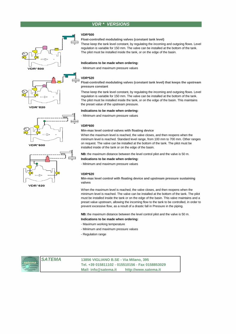
VDR*500
Float-controlled modulating valves (constant tank level)
Indications to be made when ordering:
- Minimum and maximum pressure values
VDR*520
Indications to be made when ordering:
- Minimum and maximum pressure values
VDR*600
Min-max level control valves with floating device
NB: the maximum distance between the level control pilot and the valve is 50 m.
Indications to be made when ordering:
- Minimum and maximum pressure values
VDR*620
NB: the maximum distance between the level control pilot and the valve is 50 m.
Indications to be made when ordering:
- Maximum working temperature
- Minimum and maximum pressure values
- Regulation range
SATEMA 13856 VIGLIANO B.SE - Via Milano, 395
Tel. +39 015811102 - 015510156 - Fax 0158853029
Mail: [email protected] http://www.satema.it
These keep the tank level constant, by regulating the incoming and outgoing flows. Level
regulation is variable for 150 mm. The valve can be installed at the bottom of the tank.
The pilot must be installed inside the tank, or on the edge of the basin. This maintains
the preset value of the upstream pressure.
When the maximum level is reached, the valve closes, and then reopens when the
minimum level is reached. Standard level range, from 100 mm to 700 mm. Other ranges
on request. The valve can be installed at the bottom of the tank. The pilot must be
installed inside of the tank or on the edge of the basin.
Min-max level control with floating device and upstream pressure sustaining
valves
When the maximum level is reached, the valve closes, and then reopens when the
minimum level is reached. The valve can be installed at the bottom of the tank. The pilot
must be installed inside the tank or on the edge of the basin. This valve maintains and a
preset value upstream, allowing the incoming flow to the tank to be controlled, in order to
prevent excessive flow, as a result of a drastic fall in Pressure in the piping.
Float-controlled modulating valves (constant tank level) that keeps the upstream
pressure constant
VDR * VERSIONS
These keep the tank level constant, by regulating the incoming and outgoing flows. Level
regulation is variable for 150 mm. The valve can be installed at the bottom of the tank.
The pilot must be installed inside the tank, or on the edge of the basin.
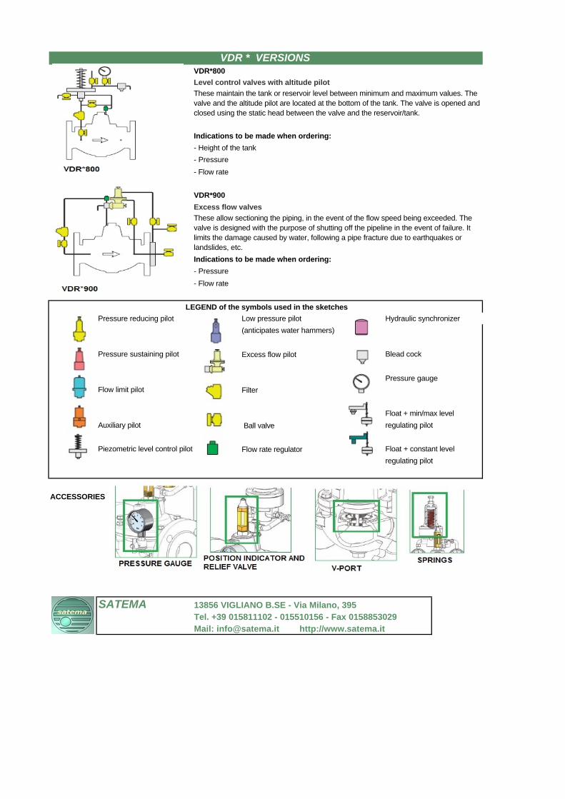
VDR*800
Level control valves with altitude pilot
Indications to be made when ordering:
- Height of the tank
- Pressure
- Flow rate
VDR*900
Excess flow valves
Indications to be made when ordering:
- Pressure
- Flow rate
Pressure reducing pilot Low pressure pilot Hydraulic synchronizer
(anticipates water hammers)
Pressure sustaining pilot Excess flow pilot Blead cock
Pressure gauge
Flow limit pilot Filter
Float + min/max level
Auxiliary pilot Ball valve regulating pilot
Piezometric level control pilot Flow rate regulator Float + constant level
regulating pilot
ACCESSORIES
SATEMA 13856 VIGLIANO B.SE - Via Milano, 395
Tel. +39 015811102 - 015510156 - Fax 0158853029
Mail: [email protected] http://www.satema.it
These allow sectioning the piping, in the event of the flow speed being exceeded. The
valve is designed with the purpose of shutting off the pipeline in the event of failure. It
limits the damage caused by water, following a pipe fracture due to earthquakes or
landslides, etc.
LEGEND of the symbols used in the sketches
VDR * VERSIONS
These maintain the tank or reservoir level between minimum and maximum values. The
valve and the altitude pilot are located at the bottom of the tank. The valve is opened and
closed using the static head between the valve and the reservoir/tank.