Embed Size (px)
Citation preview

VCS325 Series, VCS425 Series, VCS525Series Assembly Instructions
Tools Required: Knife or scissors, Phillips or Robertson (square head) screwdriver or ratchet. The use of a manual screwdriver is strongly recommended. A power drill may cause damage to the unit or stripping of the protective coating.
30007228 10/14 Rev. 1 En
WARNING! Some parts may have sharp edges. To avoid injury, wearing gloves during assembly, lifting or moving is recommended. Protective eyewear and long sleeves are also strongly recommended.
VCS325
VCS425
VCS525
CAUTION: The assembly of this grill requires two (2) people. Be careful when opening boxes packed in-side the grill to avoid scratching the stainless steel parts.CAUTION: This grill is intended ONLY to be used as a cart model, this grill cannot be built into an enclosure.NOTE: Remove the protective plastic coating from the stainless steel. Failure to do so will void the warranty.

2 30007228
VCS325/425/525 Series Assembly
4
1
5
3
1
2
Step 1: Unpack Carton and Verify ContentsRemove one (1) screw from each lower corner that fastens the hold down bracket to the barbecue. Retain these screws. Remove the wood screws that fasten the hold down bracket to the pallet. Discard four (4) wood screws and four (4) hold down brackets. Replace one (1) screw in each corner where hold down bracket was removed.
VCS325 Series Carton ContentsBox 1 (30006888)Grease PanGrease CupWarming RackBracket, Spit Rod Storage (2)Spit Rod (26")
Box 2 (30007238)Condiment Tray LeftCondiment Tray RightTowel Bar (2)Utensil Hook (3)Heat Plate (3)
Box 3Cook Grates (2) (30006527)
Box 4(LP - 30006872)(NG - 30006874)Shelf Right AssemblyShelf Right Assembly Cover Side BurnerSide Burner Assembly
Box 5 (20304920)Shelf Left AssemblyCaster Swivel (3)Caster Swivel w/ Brakes (1)Anti-tip Support Rotisserie KitLight kit
Bag 1 Instruction Package (30007233)User’s GuideAssembly InstructionsParts ListPaper Match Holder Assy.Battery ‘AAA’Lid Bumper SetHardware Bag Side ShelvesHardware Bag – Anti-tip Support Hardware Bag, Casters
VCS325
Bag 1
Hold Down Bracket
Wood Screw
VC Grill Cover
CAUTION: Be careful when opening boxes packed inside the grill to avoid scratching the stainless steel parts.

330007228
VCS325/425/525 Series Assembly
1
5
2
4
3
VCS425
VCS425 Series Carton ContentsBox 1 (30005770)Grease PanWarming RackGrease CupBracket Spit Rod Storage (2)Spit Rod 29”
Box 2 (20304957)Condiment Tray LeftCondiment Tray RightTowel Bar (2)Utensil Hook (3)Heat Plates (4)
Box 3 (30006525)Cook Grates (3)
Box 4 (LP - 30006872)(NG - 30006874)Shelf Right AssemblyShelf Right Assembly Cover Side BurnerSide Burner Assembly
Box 5 (20304920)Shelf Left AssemblyKit VC LightRotisserie KitCaster Swivel (3)Caster Swivel w/ Brakes (1)Anti-tip Support
Bag 1 Instruction Package (30007232)User’s GuideAssembly InstructionsParts ListPaper Match Holder Assy.Battery ‘AA’Lid Bumper SetHardware Bag Side ShelvesHardware Bag Anti-tip SupportHardware Bag, Casters
Step 1: Unpack Carton and Verify ContentsRemove one (1) screw from each lower corner that fastens the hold down bracket to the barbecue. Retain these screws. Remove the wood screws that fasten the hold down bracket to the pallet. Discard four (4) wood screws and four (4) hold down brackets. Replace one (1) screw in each corner where hold down bracket was removed.
Bag 1
CAUTION: Be careful when opening boxes packed inside the grill to avoid scratching the stainless steel parts.
Hold Down Bracket
Wood Screw
VC Grill Cover

4 30007228
VCS325/425/525 Series Assembly
Step 1: Unpack Carton and Verify ContentsRemove one (1) screw from each lower corner that fastens the hold down bracket to the barbecue. Retain these screws. Remove the wood screws that fasten the hold down bracket to the pallet. Discard four (4) wood screws and four (4) hold down brackets. Replace one (1) screw in each corner where hold down bracket was removed.Use a sharp cutting tool to cut the straps on the packaging and then lift off the carton top. Remove the box on the top. The sleeve surrounding the barbecue can be removed by lifting it straight up and over the top of the unit. Compare all contents to the parts list and the carton content lists below. Refer to the parts list for fastener detail.
VCS525 Series Carton ContentsBox 1 (20302911)Grease PanGrease CupWarming RackSpit RodBracket Spit Rod Storage (2)
Box 2 (20304956)Condiment Tray LeftCondiment Tray RightTowel Bar (2)Utensil Hook (3)Heat Plate (5)
Box 3 (30006526)Cook Grate (4)
Box 4 (LP - 30006872)(NG - 30006874)Shelf Right AssemblyCover Side BurnerSide Burner Assembly LPSide Burner Cook GrateBox 5 (20304920)Shelf Left AssemblyKit VC LightRotisseries Motor KitCaster Swivel (3)Caster Swivel w/ Brakes (1)Anti-tip Support
Bag 1: Instruction Package (30007232)User’s GuideAssembly InstructionsParts ListPaper Match Holder Assy.Battery “AA”Lid Bumper SetHardware Bag Side ShelvesHardware Bag Anti-tip SupportHardware Bag, Casters
5
4
1
2
3
Bag 1
CAUTION: Be careful when opening boxes packed inside the grill to avoid scratching the stainless steel parts.
Hold Down Bracket
Wood Screw
VCS525
VC Grill Cover

530007228
VCS325/425/525 Series Assembly
Step 2: Install the Casters and Anti-tip SupportThis step requires 2 people.Parts Required: (4) Casters (1 with brake; 3 without brake) (1) Anti-tip Support (1) Block (not included) (2) 10-24 Truss Head Screws (16) 1/4-20 Flange Nut (50001176) (2) 10-24 Hex NutsFigure 1NOTE: Casters (wheels) may differ from those shown in the illustration depending on the model you pur-chased.Select a side to begin installing the casters. Place a block of wood, thick telephone book or anything else available - approximately 6 inches thick - under the side to support the weight of the barbecue. Insert the four (4) bolts attached on the casters into their respective holes located on the bottom, near the front. If you have any diffi culty snapping them into place, try rotating the casters in a circular motion. As one person holds the front caster in place, the other opens the front door and installs four (4) fl ange nuts. Tighten the fl ange nuts on the front caster. Repeat this process with the rear caster. When both casters are in place on one side, re-peat the same procedure on the opposite side. After installing the casters, the corner supports must be repositioned. Do this by removing the two (2) screws securing the support, rotate the support 180° and reinstall using the same screws. (Fig. 1a)After installing the casters, install the anti-tip sup-port. Position the support under the bottom, slight-ly to the rear where the front doors meet. Fasten the support using the 10-24 screws and hex nuts supplied.
Figure 1
Rear Caster w/Brake
Blocking
Front Caster without Brake
B511
Anti-tip Support
10-24 Truss Head Screw
10-24 Hex Nut
NOTE: Tank pull out not shown.
6 30007228
VCS325/425/525 Series Assembly
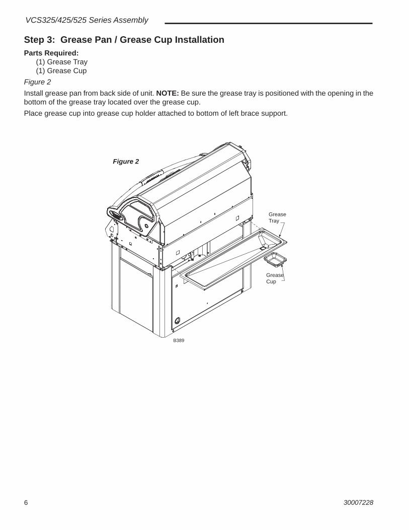
Step 3: Grease Pan / Grease Cup InstallationParts Required: (1) Grease Tray (1) Grease CupFigure 2Install grease pan from back side of unit. NOTE: Be sure the grease tray is positioned with the opening in the bottom of the grease tray located over the grease cup.Place grease cup into grease cup holder attached to bottom of left brace support.
Grease Tray
Grease Cup
B389
Figure 2

730007228
VCS325/425/525 Series Assembly
Parts Required for Steps 4, 5, 6, 7 & 8 Paper Match Holder Assembly Right Side Shelf (1) Kit Condiment Tray* (1) Kit Shelf Right**
Left Side Shelf (1) Kit Condiment Tray* (1) Kit Shelf Left***
*Kit Condiment Tray Contents (1) Condiment Tray Left (1) Condiment Tray Right (2) Towel Bars (3) Utensil Hooks **Kit Shelf Right Contents (1) Shelf Right Assy w/Support Brackets (1) Cover Side burner Assy (1) Side Burner Assembly ***Kit Shelf Left Contents (1) Shelf Left Assy w/Support Brackets

8 30007228
VCS325/425/525 Series Assembly
Left Side Shelf
Right Side Shelf
Condiment Tray Right
Condiment Tray Left
Loosen Screws From Inside
Loosen Screws From Inside
B217
Steps 4 & 5: Right & Left Side Shelf AssemblyParts Required: (1) Kit Condiment Tray (1) Condiment Tray Left (1) Condiment Tray Right (1) Hardware Bag Side Shelves (for both right and left side shelves) (1) Kit Shelf Right (1) Shelf Right Assy w/Support Brackets, Cover and Side burner Assembly installed (1) Kit Shelf Left (1) Shelf Left Assy. w/Support BracketsFigure 3Left Side ShelfLoosen two (2) screws on the support front of the left shelf assembly.Slide the front condiment tray into the gap between front support and the side panel as shown.Tighten the two (2) screws loosened earlier.Repeat for right side shelf.
Left Side Shelf Assembly
Right Side Shelf Assembly(Cover and Side burner as-sembly not shown)
Figure 3

930007228
VCS325/425/525 Series Assembly
Step 6: Attach Paper Match HolderParts Required: (1) Paper Match Holder AssemblyFigure 4 Attach the supplied paper match holder and chain assembly to the inside of the cart door.Secure chain assembly to top screw of door handle. Store chain inside door when not in use.
Figure 4
B506
NOTE: Some models may already have the match holder attached.

10 30007228
VCS325/425/525 Series Assembly
Step 7: Attach Right Shelf Assembly to GrillParts Required: Right Shelf Assembly (1) Right Shelf Assy. (Step 4) (4) 1/4-20 x 1/2” Screws (30005405) (2) #10-24 x 1/2” Screws (50000337)
Figures 5 & 6Loosely screw in (4-5 turns) four (4) 1/4-20 x 1/2” screws to the side of the grill.Place right shelf assembly onto screws.NOTE: Ensure the side burner ignitor wire is not pinched as the shelf assembly is installed into the unit.Secure (tighten) four (4) screws to the grill.Secure condiment tray to the console with one (1) #10-24 x 1/2” screw.From inside grill, attach 10-24 x 1/2” screw to the right shelf assembly.
1/4-20 x 1/2” Screw (30005405)
B438
Figure 5
B410
10-24 x 1/2” Screw (50000337)
10-24 x 1/2” Screw(50000337)
Figure 6
NOTE: Shown without Side burner.
1130007228
VCS325/425/525 Series Assembly
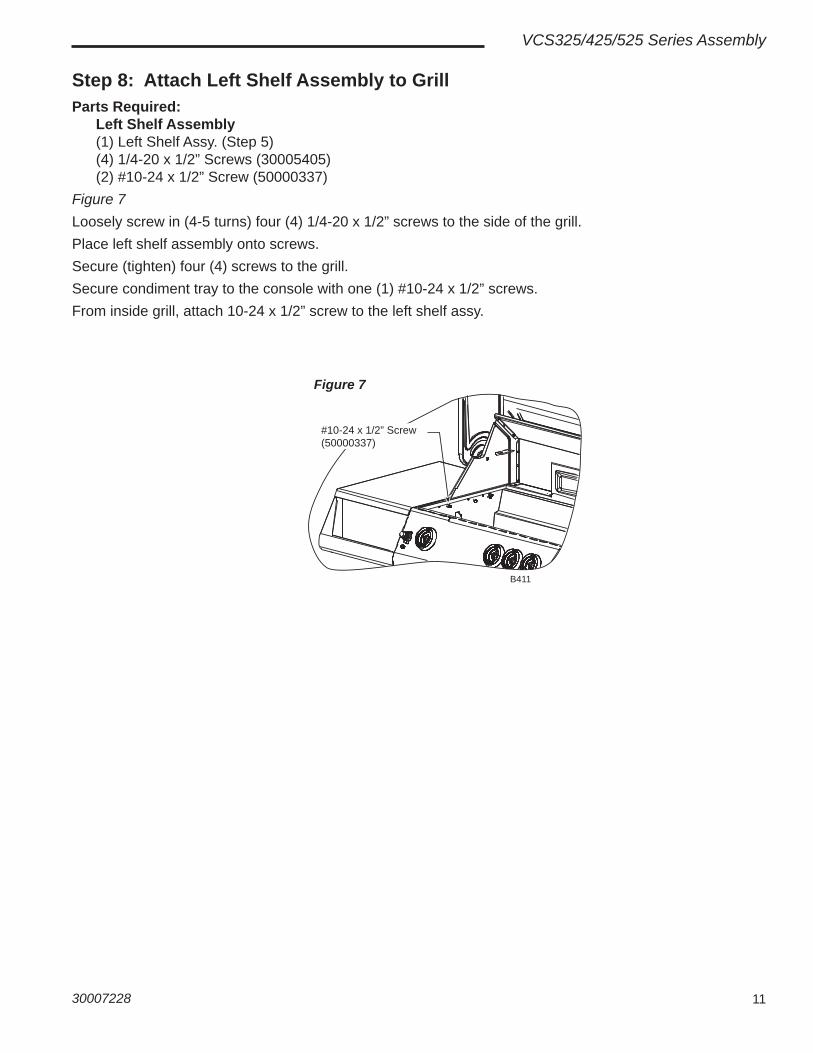
Step 8: Attach Left Shelf Assembly to GrillParts Required: Left Shelf Assembly (1) Left Shelf Assy. (Step 5) (4) 1/4-20 x 1/2” Screws (30005405) (2) #10-24 x 1/2” Screw (50000337)Figure 7Loosely screw in (4-5 turns) four (4) 1/4-20 x 1/2” screws to the side of the grill.Place left shelf assembly onto screws.Secure (tighten) four (4) screws to the grill.Secure condiment tray to the console with one (1) #10-24 x 1/2” screws.From inside grill, attach 10-24 x 1/2” screw to the left shelf assy.
#10-24 x 1/2” Screw(50000337)
B411
Figure 7

12 30007228
VCS325/425/525 Series Assembly
Step 9: Attach Towel Bars, Utensil Hooks and Spit Rod Storage BracketsParts Required Left Side Right Side (1) Towel Bar (1) Towel Bar (3) Utensil Hooks (4) #10-24 x 1/2” Screws (50000337) (4) #10-24 x 1/2” Screws (50000337)
Spit Rod Storage Bracket (2) Brackets
Towel Bars and Utensil HooksFigure 8
Slide three (3) utensil hooks into the towel bar. (Left side only)Attach towel bar with utensil hooks to left side condiment tray as shown using four (4) #10-24 x 1/2” screws.Attach towel bar without utensil hooks to right side condiment tray.Spit Rod Storage BracketsFigure 9The spit rod storage brackets are located on the back upper panel of the grill.
Towel Bar
#10-24 x 1/2” Screws (50000337)
Utensil HooksB439
Figure 8
Spit Rod Storage Bracket
B224
Figure 9
Spit Rod Storage
Rear View
B392

1330007228
VCS325/425/525 Series Assembly
Step 10: Attach Side Burner AssemblyFollow Side Burner Assembly Instructions to assemble Side Burner to unit.
Step 11: Install the Ignitor BatteryFigure 10Unscrew the ignition button from the console and insert the appropriate battery into the housing. Then screw the ignition button back into the con-sole.Check for sparks under each main burner before proceeding.
Figure 10
B393
Step 12: Install the Backlighting BatteriesNOTE: Eight (8) “AA” batteries are required for all grill models. (Not included)Figures 11Remove the battery case from the battery holder. Insert the eight (8) “AA” batteries. Attach battery case to back light wire connection. Reinstall battery case in battery holder with back light connector on the top.WARNING: Replacing the battery incorrectly might result in an explosion. Replace the battery only with the same or equivalent type recommended by the manufacturer. Dispose of used batteries according to your local environmental guidelines.
Battery Case
B440
Figure 11

14 30007228
VCS325/425/525 Series Assembly
Step 13: Install the Internal ComponentsParts Required: VCS325 (3) Sear Plates VCS425 (4) Sear Plates VCS525 (5) Sear Plates Series (2) Cooking Grates Series (3) Cooking Grates Series (4) Cooking Grates (1) Warming Rack (1) Warming Rack (1) Warming Rack (1) Smoker Box Assy (Optional) (1) Smoker Box Assy (Optional) (1) Smoker Box Assy (Optional)Figures 12, 13 & 14Carefully place each of the sear plates side by side inside the barbecue. (Fig. 12) Make sure the semicircular fi nger groove is facing toward the back of the grill. Each sear plate rests just above each burner tube. NOTE: Place the smoker box assembly on any sear plate by laying the bracket over the sear plate so the ‘z’ ends of the bracket fi t into the ‘z’ slots of the sear plate. Slide the smoker box assembly back into the locked position. (Fig. 13) Continue placing the remaining sear plates. The smoker box may be left in place when not being used. CAUTION: Only add wood chips to the smoker box when grill is cool.
Sear Plate
B413a
Figure 12
Cooking Tips - Smoker Box (Optional) • To produce more smoke and prevent fast burning, pre-soak the wood chips in a separate
bowl of water for at least 20 minutes.• To add wood chips before cooking, fi ll the smoker box with your choice of fl avored chips
(remove wood chips from water fi rst). The amount and type of wood you use is entirely up to you. Once the box is fi lled with the desired amount, close the lid and place the cooking grids in the proper position on the grill.
• Tips: Small wood chips work best inside the wood chip box.• Allow grill to heat up before placing your food on the grill. This will allow time for the wood
chips to begin to smoke.• Do not use resinous woods such as pine or plywood. These will produce an unpleasant
fl avor.• Do not try to add more wood chips while cooking. It is recommended that you allow grill to
cool before replacing wood chips or handling the cooking grates which may still be hot.
Smoker Box
B396a
Sear Plate
‘Z’ End
Figure 13

1530007228
VCS325/425/525 Series Assembly
Set the cooking grates, side by side, on the upper ledge of the grill tub. (Fig. 14) Make sure the fi nger groove is facing toward the front of the grill.Set the warming rack into the supports located on either side of the rear lid.CAUTION: Do not attempt to turn the cooking grates over while the grill is in use and the grates are hot. Doing so could result in severe burns and other injuries.
Step 13: Install the Internal Components (continued)
Warming Rack
Cooking Grates
B414
Figure 14

16 30007228
VCS325/425/525 Series Assembly
Step 14: Install the LP Cylinder (LP Models ONLY)
Parts Required: (1) LP Gas Cylinder (not included) Figures 15, 16NOTE: Check your User’s Manual for the cylinder fi lling requirements, how to attach the regulator and how to test for leaks before you try lighting the grill.CAUTION: Make sure the hose is not touching any hot or sharp surfaces.Place the LP cylinder into the hole in the tank pull out. Secure the cylinder from moving by tightening the thumb screws provided with the tank pull out assembly. (Figures 15 & 16)The fi nal step is to connect the regulator to the cylinder.CAUTION: Do not turn on/ignite the grill until after performing a leak check at all gas connection points and fi ttings. With the main LP cylinder valve OPEN, and ALL CONTROL KNOBS FULLY OFF, use a spray solu-tion of 50% liquid soap and 50% water onto all gas connection points and fi ttings. The formation of bubbles indicates an air leak that must be repaired and verifi ed with this leak test before the grill is ignited.NOTE: Ensure all plastic coatings have been removed from all stainless steel parts before using the grill.
NOTE: Typical model shown. Some models may have different construction. B512Figure 15
B513
Figure 16Thumb Screw

1730007228
VCS325/425/525 Series Assembly
Step 15: Install the Natural Gas Hose (Natural Gas (NG) Models ONLY)Figure 17Run natural gas hose through bushing provided in back panel of grill.
B441
Figure 17

18 30007228
VCS325/425/525 Series Assembly
Step 16: Install Shelf LightParts Required: (1) Cook Light (3) #10-24 x 1/2” Screws (50000337)Figures 18, 19, 20Attach the cook light to the side shelf using three (3) screws provided with kit. (Fig. 18)Battery Installation (3 “AA” alkaline batteries required, not included.)Open the battery cap by turning the cap counterclockwise as shown in Figure 19. Insert the batteries into the battery compartment according to the layout in Figure 19. Replace battery cap.
Operating InstructionsTo turn the light ON and OFF, press the ON/OFF button located on the back of the cook light. (Fig. 19)To adjust the cook light, simply move the fl exible arm as desired to achieve the best lighting for your task. After use, allow the light and grill to cool completely. Place the light face down on the shelf after use and for storage. (Fig. 20) Replace the grill cover. If a grill cover is not used, the light should be removed when not in use as rain, snow, etc. could damage the light.WARNING: The light may get hot when in close proximity to the grill surface. Do not touch the light lens when in operation. Allow it to cool.WARNING: Keep the light away from fl ammable materials.CAUTION: Do not move the cook light directly over the cook-ing area when the grill is on, as this may damage the cook light. NOTE: The light will not work until the batteries are installed.NOTE: For optimum battery life and to avoid damage to the light, we recommend you retract and turn off the light when not in use.WARNING: Replacing the battery incorrectly might result in an explosion. Replace the battery only with the same or equiva-lent type recommended by the manufacturer. Dispose of used batteries according to your local environmental guidelines.
Screws
Figure 18
B442
Figure 20
B443
Battery Cap
Flexible Arm
Cook Light Handle
ON/OFF Button
To Open
Figure 19
B209
Step 17: Rotisserie Setup(if equipped)Refer to the User’s Manual provided with the grill.

1930007228
VCS325/425/525 Series Assembly

149 Cleveland Drive • Paris, Kentucky 40361www.vermontcastingsgroup.com