Embed Size (px)
Citation preview

Variable TemperatureUnit
Technical ManualBVT3300
BRUKER
Version
003
The information in this manual may be altered without notice.
BRUKER accepts no responsibility for actions taken as a resultof use of this manual. BRUKER accepts no liability for any mis-takes contained in the manual, leading to coincidental damage,whether during installation or operation of the instrument. Un-authorised reproduction of manual contents, without writtenpermission from the publishers, or translation into another lan-guage, either in full or in part, is forbidden.
This manual was written by
P. KRENCKER and D. PODADERA
© September 7, 1998: Bruker SA
Wissembourg, France
Manual P/N: Z31349DWG-Nr: 1058 / 003

Contents
Contents ............................................................... 3
Index ..................................................................... 5
1 Description ............................................................. 71.1 Introduction ......................................................................... 71.2 BVT3300 main components ................................................. 81.3 Parts location ...................................................................... 91.4 Principle of operation ........................................................... 91.5 The front panel .................................................................. 101.6 Gas flow circuit .................................................................. 11
Setting up the gas flow ..................................................121.7 Front panel connectors ...................................................... 13
Heater connector ...........................................................13Pt100 connector ............................................................14Thermocouple connector ...............................................15RS232 connector ...........................................................16N2 connector (option) ....................................................17BCU05 connector ..........................................................17BVTB 3500 connector ....................................................18
2 Options ................................................................. 192.1 Auxiliary sensor option - BASM .......................................... 192.2 Manual Command Module - BMCM .................................... 202.3 Low temperature options ................................................... 202.4 LN2 exchanger .................................................................. 21
Exchanger presentation .................................................212.5 LN2 evaporator .................................................................. 22
Evaporator presentation .................................................222.6 BCU05 gas cooler ............................................................. 23
3 Configuration ........................................................ 253.1 Sensor selection ................................................................ 253.2 Eurotherm 847 configuration .............................................. 25
4 Remote interface control ...................................... 274.1 Microcontroller interface .................................................... 274.2 Digital interface specifications ........................................... 274.3 Commands and communication protocol ............................ 284.4 Control characters ............................................................. 284.5 List of commands .............................................................. 294.6 Rs232 link characteristics .................................................. 30
BVT3300 Version 003 BRUKER 3 (67)

4.7 Rs232 cable ...................................................................... 304.8 Authorised functions .......................................................... 30
AF (Air flow) .................................................................. 32CM (Check memory for test only) .................................. 33CO (Communications speed) ......................................... 34DL (Download) .............................................................. 35DT (DAC check for test only) ......................................... 36ES (Error status) ........................................................... 37HP (Heater power) ........................................................ 38IS (Interface status) ....................................................... 39NH (Nitrogen heater) ..................................................... 40NP (Nitrogen heater power) ........................................... 41P1 (Port 1 for test only) ................................................. 42P2 (Port 2 for test only) ................................................. 43P3 (Port 3 for test only) ................................................. 44P4 (Port 4 for test only) ................................................. 45RB (Read BBIS) ............................................................ 46SV (Software version) .................................................... 47WB (Write BBIS) ........................................................... 48WR (Write record) ......................................................... 49XR (Extract a record) ..................................................... 50
5 Technical specifications........................................515.1 Specifications ................................................................... 515.2 Security fuses ................................................................... 52
6 Schematics ............................................................53
Figures ................................................................. 63
Tables ................................................................... 65
4 (67) BRUKER BVT3300 Version 003

Index
B
BBIS eeprom....................................................................................................... 28BCU05 connector................................................................................................ 17BCU05 gas cooler ......................................................................................... 20, 23BTO2000................................................................................................. 10, 14, 25BVTB 3500 connector ......................................................................................... 18
C
CJC selection ...................................................................................................... 26
D
digital interface specification ............................................................................... 27
E
evaporator ........................................................................................................... 17exchanger ........................................................................................................... 17
F
front panel connectors......................................................................................... 13fuses.................................................................................................................... 52
G
Gas flow indicator................................................................................................ 10
H
Heater connector................................................................................................. 13
L
LN2 evaporator ................................................................................................... 20Low temperature ................................................................................................. 20
N
N2 connector....................................................................................................... 17
BVT3300 Version 003 BRUKER 5 (67)

P
Pt100 connector .................................................................................................. 14
R
remote interface control ...................................................................................... 27RS232 connector ................................................................................................ 16
S
Sensor selection.................................................................................................. 25
T
Temperature controller .......................................................................................... 7Thermocouple connector .................................................................................... 15thermocouple T ..................................................................................................... 9
6 (67) BRUKER BVT3300 Version 003

1Description 1
Introduction 1.1
0The new variable temperature unit BVT3300 for sample temperature regulation isequipped with a microcontroller interface for remote control by the host computer.The BVT3300 is manufactured in a separate housing.
The unit includes:
- A main board called interface board with a microcontroller.
- A temperature controller (EUROTHERM model 847).
- A main transformer that supplies the microcontroller and its electronics and theoptoisolated power stage of the probe heater.
- The gas flow circuitry (pressure regulator and a block of four valves for gas flowcontrol).
- An option printed circuit for LN2 heater evaporator control or LN2 exchanger.
BVT3300 Version 003 BRUKER 7 (67)

Description
Figure 1.1. BVT3300 block diagram
BVT3300 main components 1.2
The interface board has a microcontroller for remote control of the BVT3300. TwoRS232 links are available on this printed circuit. One link, on the front panel side,is for the communication with host computer and the other for communication withthe Eurotherm 847 temperature controller.
A main toric transformer supplies the different groups. At rear, there is a powersupply plug. The thyristor bridge, for heater power control, is placed on the hous-ing at rear side. On the front, a gas flow indicator with a steel ball detects the gasflow. A device, called valve block, is a group of valves which determines the gasflow under software control.
thermocouple
and Pt100
connector
RS232
Host computer
connector
probe heater
connector
BCU05
connector
Gas
inlet outlet
Gas N2
option board forLN2 evaporatoror exchanger
maintransformer
ac linefilter
Eurothermcontroller
microcontroller
POWERCONTROL
& SECURITIES
OPTO-
COUPLERSRAM
EPROM RS232
BUFF
VALVEBLOCK
GAS FLOWDETECTION
PRESSURE
REGULATORFLOW
INDICATOR
8 (67) BRUKER BVT3300 Version 003

Parts location
Parts location 1.3
Figure 1.2. Parts location
0
Principle of operation 1.4
The sample tube placed in the magnet of the spectrometer is heated by a con-stant gas flow delivered by the BVT3300. A temperature sensor (e.g. a thermo-couple T) located under the sample tube measures the gas temperature. Thetemperature controller compares the probe temperature to the target temperatureprogrammed by the operator. It controls the power applied to the heater placed atthe base of the magnet in order to stabilise the gas temperature. A special detec-tor monitors the gas flow and switch off the heater power if there is no gas flow. Asecurity thermocouple checks also the heater temperature and avoids probe over-heating.
main transformer
heater filter coil
thyristor bridge
mains plug
line switch gas flow indicator
main board
valveblock
pressure regulator
TEMPERATURE
CONTROLLER
OPTION
LN2
EVAPORATOR
EXCHANGER
BVT3300 Version 003 BRUKER 9 (67)

Description
The front panel 1.5
On the front panel, there is :
1: Auxiliary sensors
2: Gas out
3: Gas inlet
4: Pt100 connector or BTO2000
5: Power switch
6: RS232 connector
7: Heater connector
8: BCU05 connector
9: N2 connector
10: Gas flow indicator
11: BTO2000 power supply or BVTB 3500
12: Thermocouple connector type T
13: Eurotherm controller
Figure 1.3. BVT3300 front panel
BVT3300B R U K E R
HEATER BCU05
POWER
5 7 8
2
E U R O T H E R M
R MA/M PAROP1
OP2
847T
N2
GAS OUT GAS IN
BTO P.S.BVTB3500
PT100SENSOR
10 11 12 139
AUXILIARY SENSORS
DIGITAL
GAS FLOW
6
RS232
3 41
10 (67) BRUKER BVT3300 Version 003

Gas flow circuit
Gas flow circuit 1.6
On the rear panel a pressure regulator delivers gas at constant pressure to agroup of valves. Each valve, when open, let the gas flow through a calibratedhole. As all valves are in parallel, it is possible to obtain 15 different gas flow rate.
The regulator is factory adjusted to obtain approximately 2000 l/h when all valvesare open.
The default value at power on can be changed by hardware jumpers (JP6 to JP9)see figure " Valve jumpers settings " on page 45 .
On the front panel a gas flow meter with a steel ball indicates the actual gas flow.An optical barrier at the bottom detects a missing gas flow.
Figure 1.4. Gas flow circuit
GASFLOW
SENSOR
GAS FLOW REDUCERPRESSURE REGULATOR
GAS IN
VALVE CONTROL
VALVE
GAS OUT
VALVE BLOCK
BVT3300 Version 003 BRUKER 11 (67)
Description
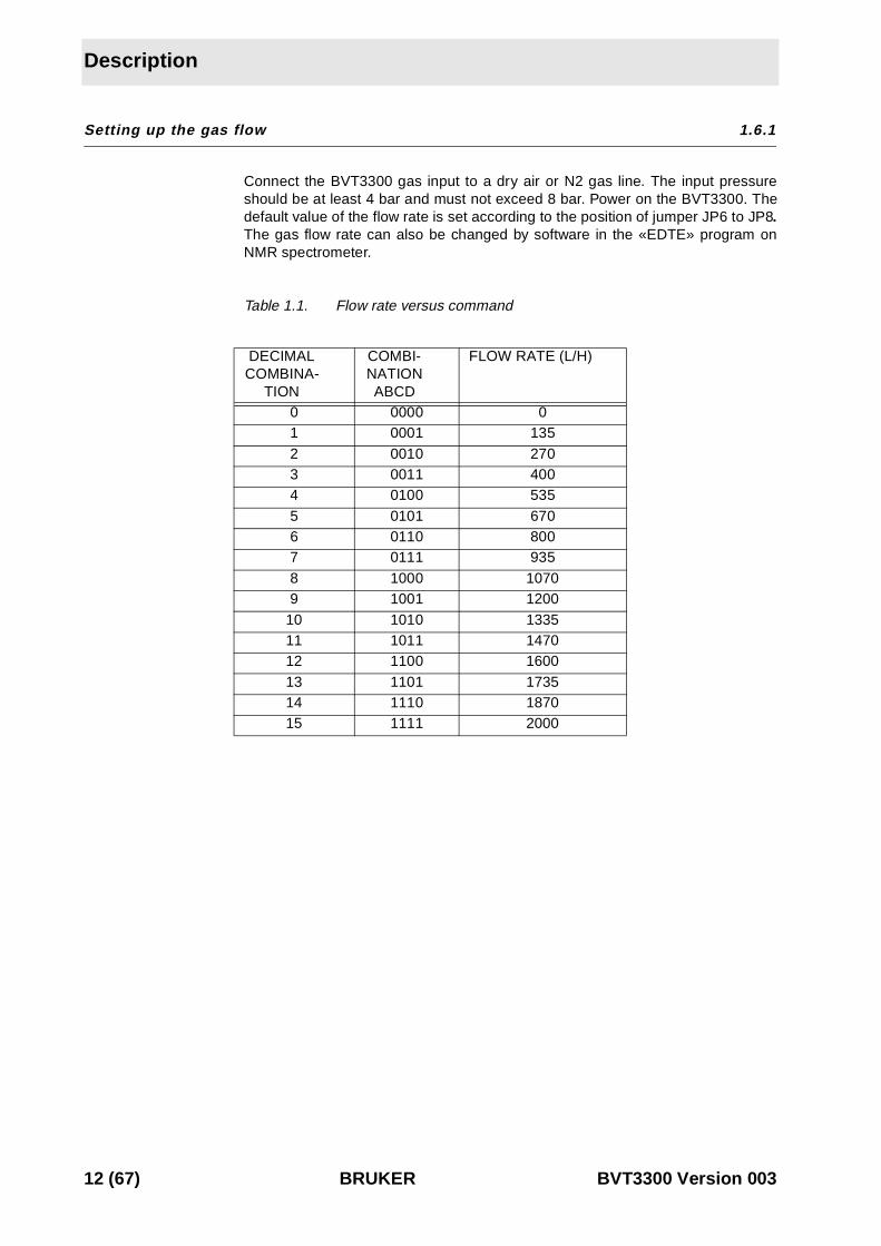
Setting up the gas flow 1.6.1
Connect the BVT3300 gas input to a dry air or N2 gas line. The input pressureshould be at least 4 bar and must not exceed 8 bar. Power on the BVT3300. Thedefault value of the flow rate is set according to the position of jumper JP6 to JP8.The gas flow rate can also be changed by software in the «EDTE» program onNMR spectrometer.
Table 1.1. Flow rate versus command
DECIMALCOMBINA-
TION
COMBI-NATION
ABCD
FLOW RATE (L/H)
0 0000 01 0001 1352 0010 2703 0011 4004 0100 5355 0101 6706 0110 8007 0111 9358 1000 10709 1001 1200
10 1010 133511 1011 147012 1100 160013 1101 173514 1110 187015 1111 2000
12 (67) BRUKER BVT3300 Version 003
Front panel connectors
Front panel connectors 1.7
Heater connector 1.7.1
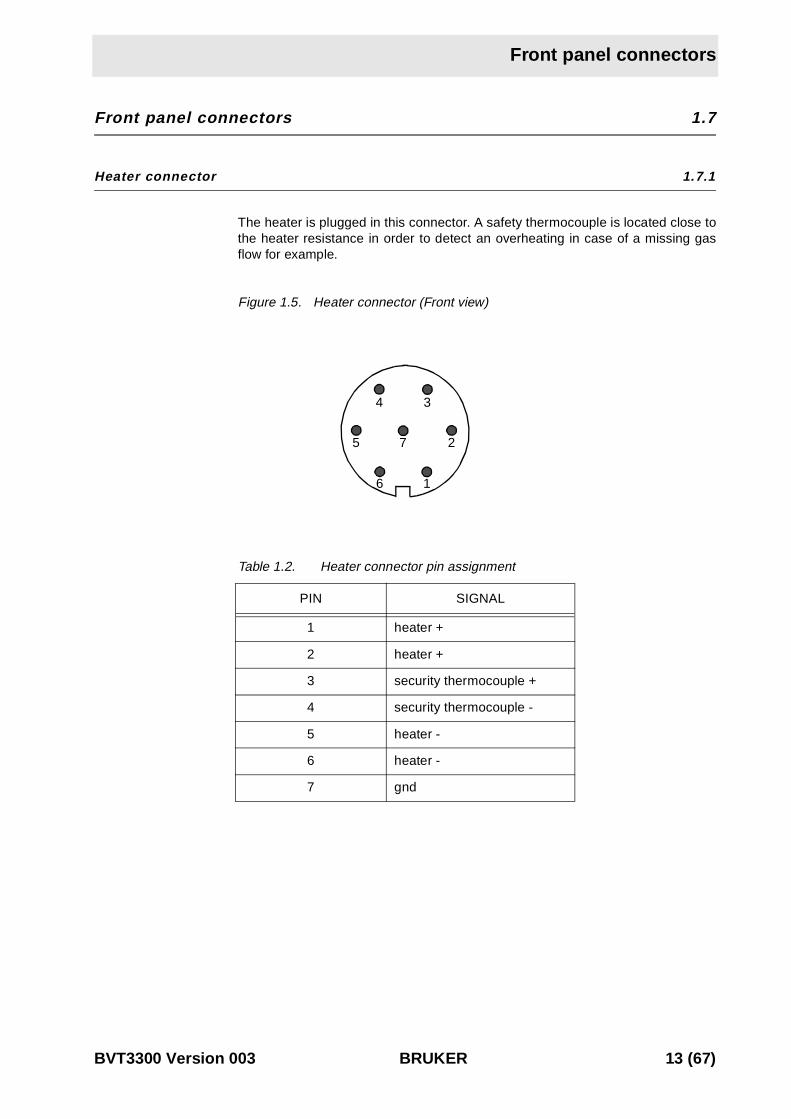
The heater is plugged in this connector. A safety thermocouple is located close tothe heater resistance in order to detect an overheating in case of a missing gasflow for example.
Figure 1.5. Heater connector (Front view)
Table 1.2. Heater connector pin assignment
PIN SIGNAL
1 heater +
2 heater +
3 security thermocouple +
4 security thermocouple -
5 heater -
6 heater -
7 gnd
4 3
2
16
5 7
BVT3300 Version 003 BRUKER 13 (67)

Description
Pt100 connector 1.7.2
Figure 1.6. Pt100 connector (front view)
Table 1.3. Pt100 connector pin assignment
➪ Note. This connector is also used to connect the BTO2000. Pin 2 and 3 areused as signal input pins.
PIN SIGNAL
1 current +
2 measure
3 measure
4 current -
1
4 3
2
14 (67) BRUKER BVT3300 Version 003

Front panel connectors
Thermocouple connector 1.7.3
Figure 1.7. Thermocouple connector (Front view)
Table 1.4. Thermocouple T pin assignment
PIN SIGNAL
1 (Cu) Shield
2 (Cu) Thermocouple +
3 (Co) Thermocouple -
T CPCONST -
1
2
3
+
BVT3300 Version 003 BRUKER 15 (67)

Description
RS232 connector 1.7.4
Figure 1.8. RS232 male connector (Front view)
Table 1.5. Rs232 connector pin assignment
PIN SIGNAL
1 NC
2 RxD
3 TxD
4 NC
5 GND
6 NC
7 RTS
8 DTR
9 NC
1 2 3 4 5
7 986
16 (67) BRUKER BVT3300 Version 003

Front panel connectors
N2 connector (option) 1.7.5
Figure 1.9. N2 connector (Front view)
Table 1.6. Evaporator connector pin assignment
BCU05 connector 1.7.6
Figure 1.10. BCU05 connector
Table 1.7. BCU05 connector pin assignment
PIN NUMBER SIGNAL NAME COMMENT
1 heater + power output (0 - 40 vac)
2 level sensor + level detection input (0 - 2,5 v)
3 evaporator detection evaporator detected if grounded
4 gnd ground (0 v)
5 heater - ground power
6 exchanger detection exchanger detected if grounded
PIN NUMBER SIGNAL NAME COMMENT
1heater on (output) turns on the BCU05
when high (> 2,4v)
2 dgnd digital ground
3 nc not connected
4
3
2
1
6
5
3
2
1
BVT3300 Version 003 BRUKER 17 (67)
Description
BVTB 3500 connector 1.7.7
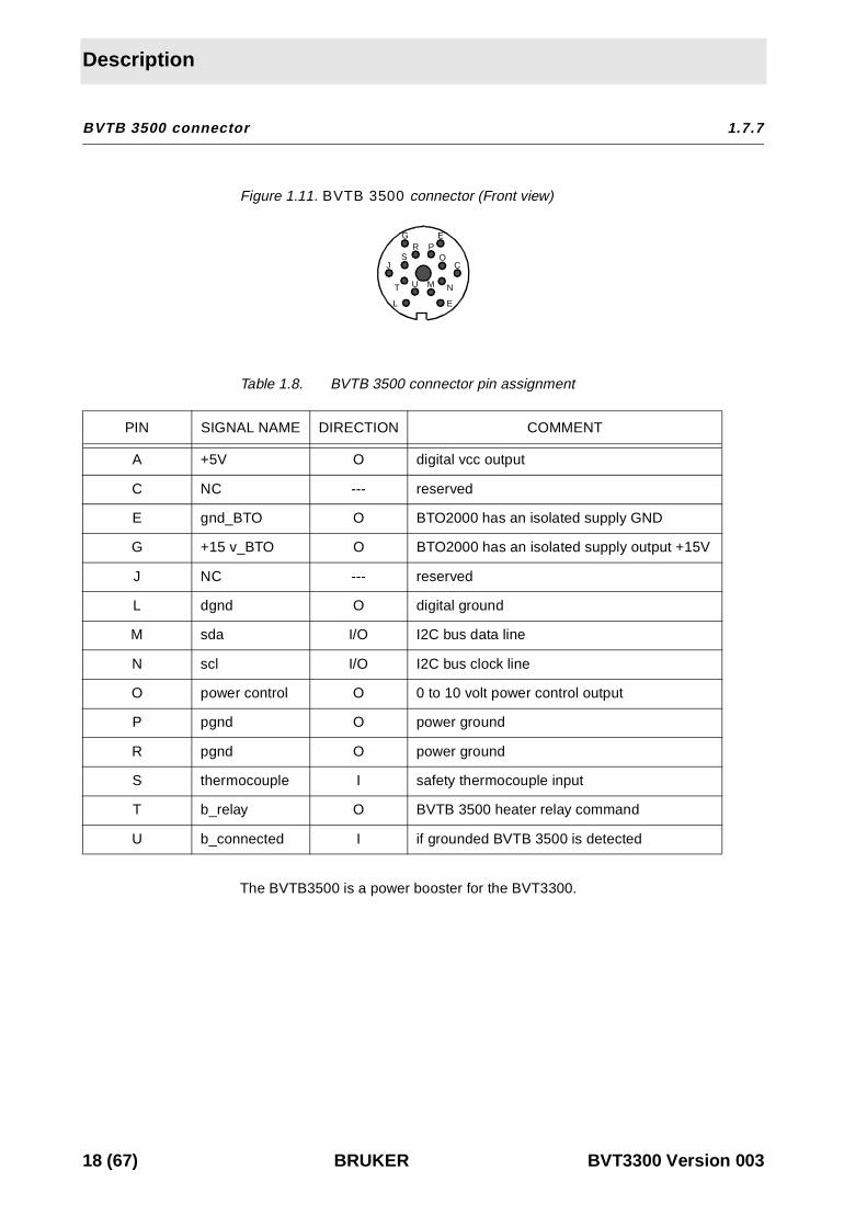
Figure 1.11. BVTB 3500 connector (Front view)
Table 1.8. BVTB 3500 connector pin assignment
The BVTB3500 is a power booster for the BVT3300.
PIN SIGNAL NAME DIRECTION COMMENT
A +5V O digital vcc output
C NC --- reserved
E gnd_BTO O BTO2000 has an isolated supply GND
G +15 v_BTO O BTO2000 has an isolated supply output +15V
J NC --- reserved
L dgnd O digital ground
M sda I/O I2C bus data line
N scl I/O I2C bus clock line
O power control O 0 to 10 volt power control output
P pgnd O power ground
R pgnd O power ground
S thermocouple I safety thermocouple input
T b_relay O BVTB 3500 heater relay command
U b_connected I if grounded BVTB 3500 is detected
J
E
C
E
O
NMU
L
GPR
S
T
18 (67) BRUKER BVT3300 Version 003

2Options 2
Auxiliary sensor option - BASM 2.1
The BVT3300 can be equipped with an electronic module for auxiliary tempera-ture measurement.
This module can receive up to 4 sensors to acquire more temperature in spec-trometer environement (ambient temperature, extra temperature in special probehead for exemple).
Figure 2.1. BASM front view
The module is inserted in the front of the BVT3300 unit and has a flat cable whichmust be connected to the interface board.
CH0 CH1 CH2 CH3
module with 4 Pt100 inputs
module with 4 thermocouple inputs
CH0 CH1 CH2 CH3
BVT3300 Version 003 BRUKER 19 (67)

Options
Manual Command Module - BMCM 2.2
The BMCM is an electronic module which allows to control manually the mainfunctions of the temperature unit.
Figure 2.2. BMCM Front view
The following functions of the temperature unit can be controlled :
• Probe Heater : the left push button of the module turns on the main probeheater. The heater status is indicated by a green led in the button.
• LN2 Heater : the right push button turns on the LN2 evaporator heater. TheLN2 evaporator heater status is indicated by a green led in the button. The sta-tus of the LN2 level sensors are indicated by two red leds on the bottom. TheLN2 heater power can be set with rightmost potentiometer.
• Gas flow control : a knob permits to select manually stepwise a gas flowbeetween 0 and 2000 l/h.
The module is inserted in the front of the BVT3300 unit and has 4 flat cableswhich must be connected to the interface board.
Low temperature options 2.3
For sample temperature regulation below room temperature one must use coldgas. The BVT3300 can be equipped with three optional cold gasproduction devices :
• LN2 exchanger
• LN2 evaporator
• BCU05 gas cooler
The level of the LN2 tank is monitored by software and the power level applied tothe LN2 heater is computer controlled. For both first options, an additional printedcircuit must be mounted in the enclosure. The LN2 heater cable or the exchangercable is plugged in the N2 option connector on the front panel.
LN2 HEATER
ON/OFF ON/OFF
HEATER
REFILL
LN2 LEVEL
EMPTY
1 15
8
POWER
FLOW LN2
20 (67) BRUKER BVT3300 Version 003

LN2 exchanger
LN2 exchanger 2.4
0 ThNeue DokumenteFor sample temperature regulation below room temperature one mustuse coldThis option allows to extend regulation temperature below room temperature. It isnecessary to have an nitrogen gas line to use this device. The N2 gas is cooled bycirculating in a heat exchanger tube that soaks in liquid nitrogen. The cold gas istransferred to the probe trough a flexible transfer line.
➪ The gas flow is stopped (it means all four valves are closed) whenever theheater power is off, avoiding sample freezing.
Regulation accuracy is unchanged.
Exchanger presentation 2.4.1
Figure 2.3. Exchanger principle
Tube
Liquid nitrogen
Isothermal tank
Refill level sensor
Empty level sensor
Valve block
Transfer line
N2 gas in Cold N2 out
BVT3x00
BVT3300 Version 003 BRUKER 21 (67)
Options
LN2 evaporator 2.5
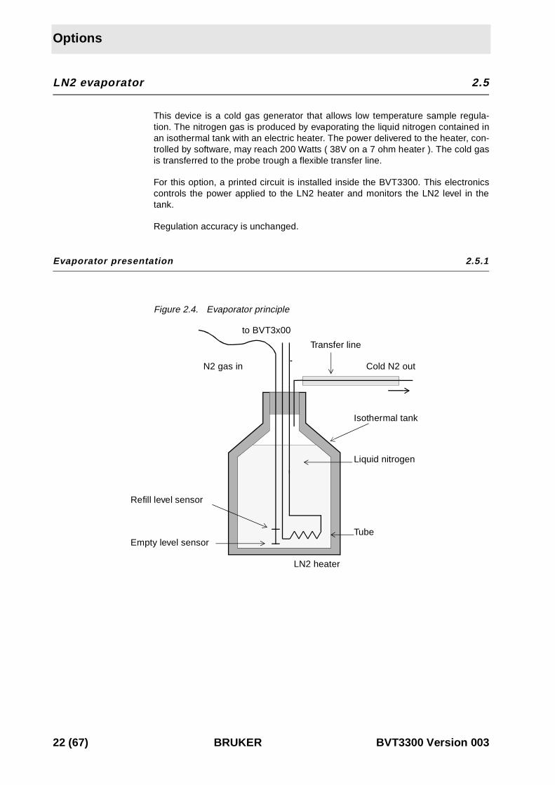
This device is a cold gas generator that allows low temperature sample regula-tion. The nitrogen gas is produced by evaporating the liquid nitrogen contained inan isothermal tank with an electric heater. The power delivered to the heater, con-trolled by software, may reach 200 Watts ( 38V on a 7 ohm heater ). The cold gasis transferred to the probe trough a flexible transfer line.
For this option, a printed circuit is installed inside the BVT3300. This electronicscontrols the power applied to the LN2 heater and monitors the LN2 level in thetank.
Regulation accuracy is unchanged.
Evaporator presentation 2.5.1
Figure 2.4. Evaporator principle
Tube
Liquid nitrogen
Isothermal tank
Refill level sensor
Empty level sensor
Transfer line
N2 gas in Cold N2 out
LN2 heater
to BVT3x00
22 (67) BRUKER BVT3300 Version 003
BCU05 gas cooler
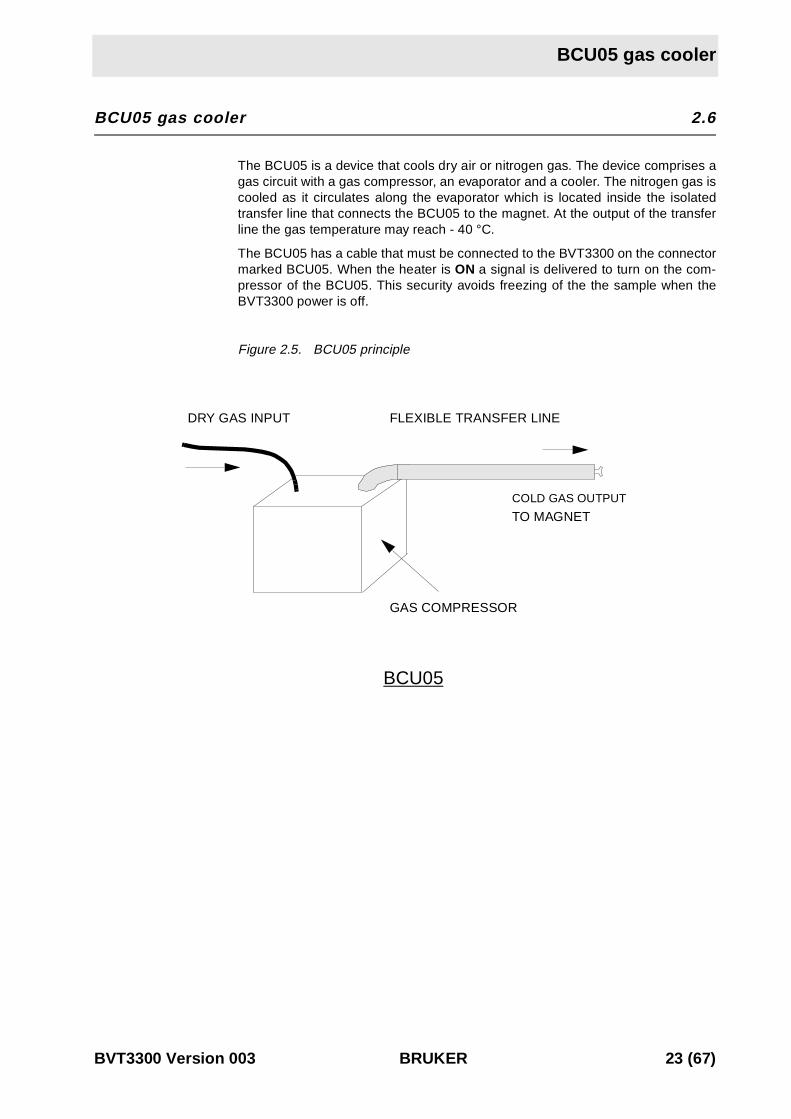
BCU05 gas cooler 2.6
0The BCU05 is a device that cools dry air or nitrogen gas. The device comprises agas circuit with a gas compressor, an evaporator and a cooler. The nitrogen gas iscooled as it circulates along the evaporator which is located inside the isolatedtransfer line that connects the BCU05 to the magnet. At the output of the transferline the gas temperature may reach - 40 °C.
The BCU05 has a cable that must be connected to the BVT3300 on the connectormarked BCU05. When the heater is ON a signal is delivered to turn on the com-pressor of the BCU05. This security avoids freezing of the the sample when theBVT3300 power is off.
Figure 2.5. BCU05 principle
BCU05
DRY GAS INPUT FLEXIBLE TRANSFER LINE
TO MAGNET
GAS COMPRESSOR
COLD GAS OUTPUT
BVT3300 Version 003 BRUKER 23 (67)

Options
24 (67) BRUKER BVT3300 Version 003

3Configuration 3
Sensor selection 3.1
0
The BVT3300 can be used with three types of sensors:
• Thermocouple T (factory set)
• BTO2000
• PT100 sensor
➪ Warning: Never connect two types of sensors at a same time on theBVT3300.
Eurotherm 847 configuration 3.2
0
The EUROTHERM 847 controller must be configured to work with the right type ofsensor.
To access the configuration mode, a switch located inside the 847 controller mustbe closed.
➪ The switch must be closed only during the configuration mode.
Proceed as follows:
- Switch off the main power.
- Unscrew the EUROTHERM controller front plate.
- Remove the module out of its cabinet.
The switch WB1 is located on the left side at the rear of the module.
- Close the switch.
- Insert the controller module and screw the front panel.
- Switch on the main power.
- Press the button until «Sn» appears. («Sn» is the mnemonic for sen-
sor). Then select the sensor type: press the up or down key until
the correct sensor appears "Eurotherm 847 sensor selection" on page 26.
PAR
BVT3300 Version 003 BRUKER 25 (67)

Configuration
.
If the sensor is a thermocouple or a BTO2000 you must select also the type of
(Cold Junction Compensation). Press the par key until CJC appears and
select with the up and down key. See table "CJC selection" on page 26 .
- When the configuration is finished, switch off the main power, remove again the
controller and open the switch.
- finely close the controller and switch on the power supply.
Table 3.1. Eurotherm 847 sensor selection
sensor type Sn
T thermocouple internal CJC t tc
BTO2000 t tc
Pt100 rtd3
Table 3.2. CJC selection
sensor type Cjc
T thermocouple int (internal)
BTO2000 0 °C (external at 0 °C)
Pt100 X (don’t care)
PAR
26 (67) BRUKER BVT3300 Version 003
4Remote interfacecontrol 4
4000000
Microcontroller interface 4.1
This interface has several functions:
• Host computer - EUROTHERM transparent communication trough a serial port
• Transmission of BVT3300 internal status to host computer.
• Probe heater on/off control
• Gas flow control.
• Installed option control:
1. Evaporator heating power control.
2. Exchanger control with nitrogen level detection.
- etc.
Optoisolated inputs receive informations and securities flags:
• Probe heater overheating flag.
• Gas flow detection.
• LN2 level monitoring (when option available).
• Probe heater power status flag (on/off).
• etc.
Eight optoisolated outputs (PORT3) transmit the control byte for the DAC that de-livers the LN2 heater control signal.
Digital interface specifications 4.2
Microcontroller:
8 bits 8032 microcontroller clocked at 11,05 MHz
Program Memory:
Flash EPROM 64 K. A new firmware can be downloaded in this memory via theRS232 link.
Sram:
32 Kilobytes
BVT3300 Version 003 BRUKER 27 (67)

Remote interface control
Eeprom:
256 bytes for manufacturing informations storage (BBIS informations).
Interface:
• Serial link to EUROTHERM controller:
9600 bauds,1 start bit, even parity, 1 stop bit and three wires link. Baudrate canbe changed by software with the «CO» command.
• Serial link to host computer:
9600 bauds,1 start bit, even parity, 1 stop bit and three wires link.
Isolation:
Optocouplers 2500 volt isolation between digital interface and power section.
Power supply:
+5 volt, I < 1 ampère.
Commands and communication protocol 4.3
All commands for the Eurotherm controller cross over the interface. The micro-controller decodes each received command and decides then for whom the com-mand is intended (either for the interface itself or the Eurotherm controller). Acommand that is not an interface command is automatically transferred to the Eu-rotherm controller. If the command is processed by the Eurotherm, the answer isreturned to the host computer via the interface.
Control characters 4.4
Six non printing ASCII characters are used to control the messages that are ex-changed between host computer and BVT3000.
Table 4.1. Control characters.
NAME HEX FUNCTION
STX 02 Start of text
ETX 03 End of text
EOT 04 End of transmission
ENQ 05 Enquiry
ACK 06 Acknowledge
NACK 15 Negative acknowledge
28 (67) BRUKER BVT3300 Version 003

List of commands
List of commands 4.5
Table 4.2. List of commands
COMMANDS R W COMMENT
AF X X reads / writes gas flow delivery
CM X starts a ram test of the microcontroller (for test only)
CO X X reads / writes communication speed (Interface <-> Eurotherm)
DL X X reads the download transfer status/ initialises a download transfer
DT X DAC check (for test only)
ES X reads the error status
HP X X reads / writes heater power state ('1' or '0')
IS X reads interface status
NH X X reads / writes LN2 heater power level
NP X X reads / writes LN2 heater power state ('1' or '0')
P1 X X reads / writes port 1 (for test only)
P2 X X reads / writes port 2 (for test only)
P3 X reads port 3 (for test only)
P4 X reads port 4 (for test only)
SV X reads interface version (software, hardware and installed options)
RB X reads BBIS memory content
WB X writes to a BBIS memory location
WR X writes a record to the BVT3000
XR X transmit a hexadecimal record to the host
BVT3300 Version 003 BRUKER 29 (67)

Remote interface control
Rs232 link characteristics 4.6
The serial link allows a host computer to communicate with the BVT3000. It is athree wires link with no hardware or software handshake. The communication pa-rameters are 9600 bauds, 1 start bit, even parity, 1 stop bit. RS232 connector pinassignment and names are explained abovein table "Rs232 connector pin as-signment " on page 16 .
Rs232 cable 4.7
A cable with two 9 pins female connectors is required to link the host computer tothe BVT3000. The maximum recommended cable length is 10 meters (30 feet).The cable shield is connected to the connector’s case.
Figure 4.1. RS232 cable.
Authorised functions 4.8
The microcontroller detects automatically the installed optional board (LN2 evapo-rator or LN2 exchanger) and the devices connected on the front panel (exchangeror evaporator). The firmware authorises only the use of the functions relative tothe installed options. Let us suppose, for instance, the N2 exchanger is installed:you cannot use the evaporator functions. The answer to an unauthorised functionwill be a «NACK» . The following table gives the different possible options andtheir authorised functions. In this table, «X» means authorised and a empty cellmeans unauthorised.
1
2
3
4
5
6
7
8
9
DCD
RxD
TxD
DTR
GND
DSR
RTS
CTS
RI
Acquisition rackserial interface board
BVT3000or BVT3300
Sub 9 female connectorSub 9 female connector
1
2
3
4
5
6
7
8
9
DCD
RxD
TxD
DTR
GND
DSR
RTS
CTS
RI
30 (67) BRUKER BVT3300 Version 003

Authorised functions
Table 4.3. Authorised commands
COMMANDS STANDARDWITH
EVAPORATORWITH
EXCHANGERPROBLEM
AF X X X X
CM X X X
CO X X X
DL X X X
DT X X X
ES X X X
HP X X X
IS X X X X
NH X
NP X
P1 X X X X
P2 X X X X
P3 X X X X
P4 X X X X
SV X X X X
RB X X X X
WB X X X X
WR X X X X
XR X X X X
BVT3300 Version 003 BRUKER 31 (67)

Remote interface control
AF (Air f low) 4.8.1
Write
Syntax: EOT 0 0 0 0 STX AF>ABCD ETX BCC
Response: ACK
Description: This command allows to control the gas flow delivery.
Rules: The unit has four gas flow valves. ABCD represent the value of thedelivery. Each character represent one valve state (a part of the maximum deliv-ery) and can only be «0» or «1». The total delivery is the amount of the four indi-vidual deliveries. A NACK is send if one of these characters is not «0» or «1».Table " Flow rate versus command " on page 12 shows the different gas flow de-liveries.
Example: If ABCD is set to «1100» (12 decimal), The delivery corresponds to1600 litres per hour.
NB: After power on the microcontoller reads 4 jumpers (JP6-JP8) located on theinterface printed circuit. Each jumper can be switched between position marked«1» and «0». Each jumper represents a valve; in position «0» the valve will beclosed. JP6 represents valve D and JP8 valve A. The initial flow rate is set accord-ing to the combination of all jumpers.
WARNING: Space characters are not allowed.
Read
Syntax: EOT 0 0 0 0 AF ENQ
Response: STX AF > Value ETX BCC
Description: This command allows to read the actual gas delivery.
Rules: Value is a 4 characters string. Table 2.1." Flow rate versus com-mand" on page 12 shows the different gas flow deliveries.
32 (67) BRUKER BVT3300 Version 003

Authorised functions
CM (Check memory for test only) 4.8.2
Read
Syntax: EOT 0 0 0 0 CM ENQ
Response: ACK if the RAM test has complete.
NACK if the test failed.
Description: The CM command starts a complete microcontroller ram test.
WARNING: After the (ACK or NACK) answer the interface is always RESET.
BVT3300 Version 003 BRUKER 33 (67)
Remote interface control
CO (Communications speed) 4.8.3
Write
Syntax: EOT 0 0 0 0 STX CO ABCDE ETX BCC
Response: ACK
Description: CO command allows to program the Eurotherm - interface speedcommunication. After power on, speed communication is set to 9600 Bauds.
Rules: ABCDE represent the baud rate. It is a five characters string. Thisstring can have one of the following values:
A B C D E
1 9 2 0 0
_ 9 6 0 0
_ 4 8 0 0
_ 2 4 0 0
_ 1 2 0 0
NB: _ represent the space character. It can be replaced by '0'.
Read
Syntax: EOT 0 0 0 0 STX CO ENQ
Response: STX CO ABCDE ETX BCC
Description: It allows to read the Interface - Eurotherm communication speed.
Rules: «ABCDE» represent the baud rate. It is a 5 characters string. Thestring is can have the following values:
A B C D E
1 9 2 0 0
_ 9 6 0 0
_ 4 8 0 0
_ 2 4 0 0
_ 1 2 0 0
NB: _ represent the space character.
34 (67) BRUKER BVT3300 Version 003
Authorised functions
DL (Download) 4.8.4
Write
Syntax: EOT 0 0 0 0 STX DL val ETX BCC
Response: ACK if command issues.
NACK in all other cases.
Description: DL initializes down-load. This command must be repeated twotimes successfully to enter in the mode which allows the host to transfer code.
Take care: Flash Eprom is erased on the second DL command.
On second DL1 command, regulation is interrupted. Heater, evaporator and gasflow are switched off. All the software user function are inaccessible.
Rules: Val can be «0» or «1».
- «0» stops down-load. If the download is in progress, a new one must be per-formed completely to make the BVT3X00 run correctly.
- «1» initializes down-load. The «DL1» command must be send twice to start theprocess (FLASH erased).
Read
Syntax: EOT 0 0 0 0 DL ENQ
Response: STX DL val ETX BCC
Description: Allows the user to get information about down-load.
Rules: Val = '0': No down-load in progress.
Val = '1': Down-load in progress but flash eprom is not erased.
Val = '2': Down-load in progress and flash eprom erased.
BVT3300 Version 003 BRUKER 35 (67)

Remote interface control
DT (DAC check for test only) 4.8.5
Syntax: EOT 0 0 0 0 DT state ETX BCC
Response: ACK
Description: DT starts a LN2 DAC test.
Rules: state can be «0» or «1».
1 means test on.
0 means test off.
00 COMMANDS0
36 (67) BRUKER BVT3300 Version 003

Authorised functions
ES (Error status) 4.8.1
Read
Syntax: EOT 0 0 0 0 ES ENQ
Response: STX ES val ETX BCC
Description: Allows the user to get information about the last six errors.
Explanations: At each «ES» request, the last happened error code is sent andthen reset. If more than six errors are memorised, the oldest error code is re-placed by the new one. To erase all errors, the user must send «ES» requests un-til response is «ES0».
The returned value «Val» inform about error. The different error codes are givenbelow.
Write
Syntax: EOT 0 0 0 0 STX ES val ETX BCC
Response: Always NACK.
Table 4.4. Error status description
VAL SIGNIFICATION COMMENT
0 NOERROR no error in command
1 SYNTAX unknown command/syntax error
2 checksum checksum error
3 erasefail flash eprom erase error
4 programmfail flash eprom program error
5 wrongrecordtype no intel hex record
6 wrongaddress program address out of range
7 wrongchecksum checksum error intel hex
8 wrongtransmissioncheck wrong eof record
9 wrongdatacount byte counter error
10 noappsw no application software
11 nobbis no BBIS available
12 bbiscs1 BBIS checksum error block 1
13 bbiscs2 BBIS checksum error block 2
14 bbiscs3 BBIS checksum error block 3
15 bbiscs4 BBIS checksum error block 4
BVT3300 Version 003 BRUKER 37 (67)

Remote interface control
HP (Heater power) 4.8.2
Write
Syntax: EOT 0 0 0 0 STX HP state ETX BCC
Response: ACK If state equals «0» or «1»
NACK In all other cases
Description: This command allows to switch ON or OFF the gas flow heating.
Rules: State can be «0» or «1».
«1» switch the heater ON
«0» switch the heater OFF
All other values are ignored.
WARNING: Space characters are not allowed.
Read
Syntax: EOT 0 0 0 0 HP ENQ
Response: STX HP state ETX BCC
Description: This command allows to read the heater's state.
Rules: State can be '0' or '1'.
«1» means that heater is ON
«0» means that heater is OFF
NB: after power on the heater is OFF.
38 (67) BRUKER BVT3300 Version 003

Authorised functions
IS (Interface status) 4.8.3
Read
Syntax: EOT 0 0 0 0 IS ENQ
Response: STX IS > ABCD ETX BCC
Description: This command allows to read back the interface status.
Rules: The status word is made of sixteen bits, each one represents a par-ticular function of the interface as detailed below. The 16 bits are send as fourhexadecimal numbers preceded by «>» to warn the computer that the data is hex-adecimal. Digits ABCD are ASCII characters representing a hexadecimal digit (0-9, A-F).
Interface Status (IS) in the format (>ABCD)
Table 4.5. Interface status
DIGIT BIT SIGNAL NAME FUNCTION
D1 0 heater on 1= heater is ON
D2 1 not used always 0
D3 2 evap conn 1 = evaporator connected
D4 3 missing gas flow 1 = missing gas flow
C1 4 overheating 1 = heater overheating
C2 5 exch conn 1 = exchanger connected
C3 6 LN2 refill 1 = refill LN2 tank
C4 7 LN2 empty 1 = LN2 tank is empty.
B1 8 evaporator status 1 = LN2 heater is on
B2 9 not used 1 always
B3 10 booster connected 1 = BVTB3500 present
B4 11 reserved 0 always
A1 12 reserved 0 always
A2 13 reserved 0 always
A3 14 reserved 0 always
A4 15 reserved 0 always
BVT3300 Version 003 BRUKER 39 (67)

Remote interface control
NH (Nitrogen heater) 4.8.4
Write
Syntax: EOT 0 0 0 0 STX NH Value ETX BCC
Response: ACK
Description: This command allows to control LN2 heater power (Evaporator).
Rules: The value from 0 up to 100%, is defined as a string up to 5 charac-ters long. The string can begin with 1 to 5 spaces or «0». After power on, the initialvalue is set to 0 (the nitrogen heater is OFF).
Read
Syntax: EOT 0 0 0 0 NH ENQ
Response: STX NH Value ETX BCC
Description: This command allows to read back LN2 heater power.
Rules: Value from 0 to 100%, is a string up to 5 characters long. The stringcan begin with 1 to 5 spaces or «0».
NB: Value is a DECIMAL code.
40 (67) BRUKER BVT3300 Version 003
Authorised functions
NP (Nitrogen heater power) 4.8.5
Write
Syntax: EOT 0 0 0 0 STX NP state ETX BCC
Response: ACK
Description: Allows to switch nitrogen heater power ON or OFF.
Rules: State can be «0» or «1».
«1» switch LN2 heater ON.
«0» switch LN2 heater OFF.
WARNING: Space characters are not allowed.
Read
Syntax: EOT 0 0 0 0 NP ENQ
Response: STX NP State ETX BCC
Description: Allows to read Nitrogen Power.
Rules: State can be «0» or «1».
State at «1» means that LN2 heater is ON.
State at «0» means that LN2 heater is OFF.
NB: After power on the nitrogen heater power is at «0».
BVT3300 Version 003 BRUKER 41 (67)

Remote interface control
P1 (Port 1 for test only) 4.8.6
This port represents the main status of the BVT3000 unit.
Port 1 is described in the following table
Table 4.6. Port 1 definition
Write
Syntax: EOT 0 0 0 0 STX P1 AB ETX BCC
Response: ACK
Description: Allows to write directly to port 1.
Rules: The first character represents the state of port 1 bits 4 to 7. Thesecond character represents the state of the bits 0 to 3. The characters are hexa-decimal.
Read
Syntax: EOT 0 0 0 0 P1 ENQ
Response: STX P1 > ABCD ETX BCC
Description: Allows direct read access to port 1.
Rules: A and B are always «0». The third character represents the state ofport 1 bits 4 to 7. The fourth character represents the state of the bits 0 to 3. Allthe characters are hexadecimal.
BIT NAME FUNCTION
0 heater 1 = Probe heater is ON
1 aux1 Unused
2 evaporator 1 = LN2 heater is ON (with option)
3 aux2 Unused
4 valve1 1 = Valve 1 open
5 valve2 1 = Valve 2 open
6 valve3 1 = Valve 3 open
7 valve4 1 = Valve 4 open
42 (67) BRUKER BVT3300 Version 003

Authorised functions
P2 (Port 2 for test only) 4.8.7
The power level applied to the Ln2 evaporator is set by an analog control signalcoming from a 8 bit DAC (Digital to Analog Converter). Port 2 provides the bits forLN2 control DAC:
Table 4.7. Port2 definition
Write
Syntax: EOT 0 0 0 0 STX P2 AB ETX BCC
Response: ACK
Description: Allows direct write access to port 2.
Rules: The first character represents the state of port 2 bits 4 to 7. Thesecond character represents the state of the bits 0 to 3. The characters are hexa-decimal.
Read
Syntax: EOT 0 0 0 0 P2 ENQ
Response: STX P2 > ABCD ETX BCC
Description: Allows direct read access to port 2.
Rules: A and B are always «0». The third character represents the state ofport 2 bits 4 to 7. The fourth character represents the state of the bits 0 to 3. Allthe characters are hexadecimal.
BIT NAME FUNCTION
0 1LN2 DAC bit 0
1 2LN2 DAC bit 1
2 3LN2 DAC bit 2
3 4LN2 DAC bit 3
4 5LN2 DAC bit 4
5 6LN2 DAC bit 5
6 7LN2 DAC bit 6
7 8LN2 DAC bit 7
BVT3300 Version 003 BRUKER 43 (67)
Remote interface control
P3 (Port 3 for test only) 4.8.8
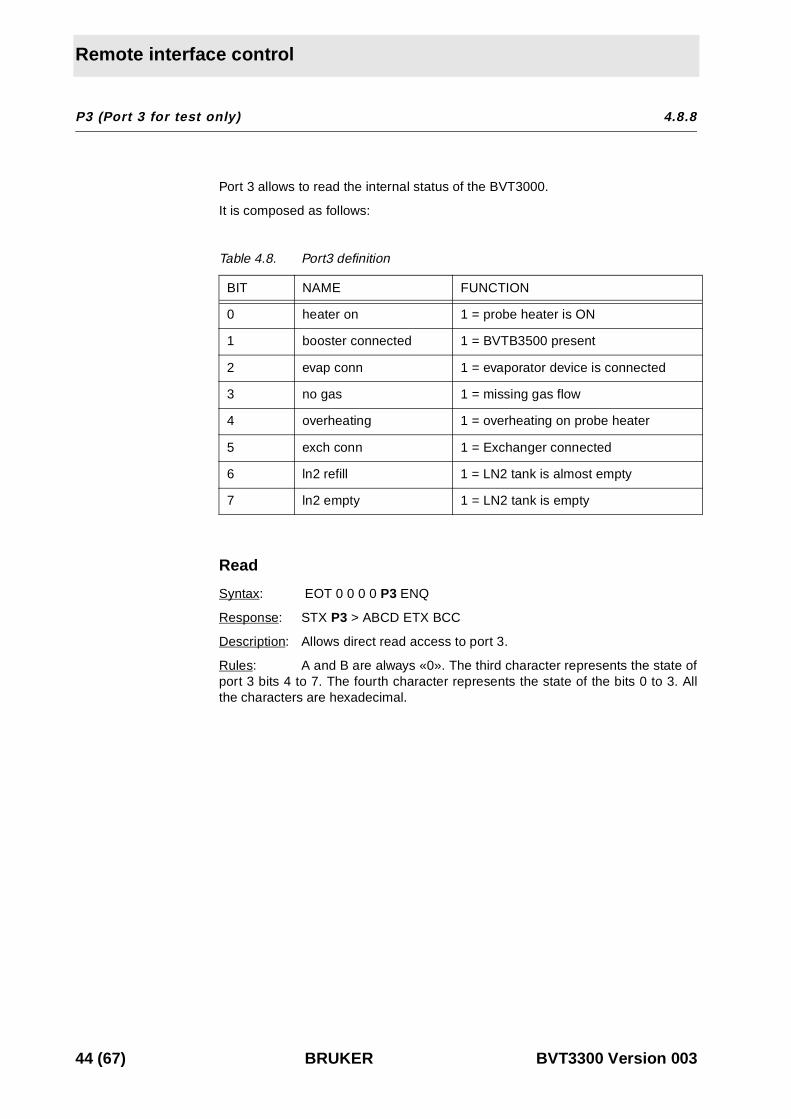
Port 3 allows to read the internal status of the BVT3000.
It is composed as follows:
Table 4.8. Port3 definition
Read
Syntax: EOT 0 0 0 0 P3 ENQ
Response: STX P3 > ABCD ETX BCC
Description: Allows direct read access to port 3.
Rules: A and B are always «0». The third character represents the state ofport 3 bits 4 to 7. The fourth character represents the state of the bits 0 to 3. Allthe characters are hexadecimal.
BIT NAME FUNCTION
0 heater on 1 = probe heater is ON
1 booster connected 1 = BVTB3500 present
2 evap conn 1 = evaporator device is connected
3 no gas 1 = missing gas flow
4 overheating 1 = overheating on probe heater
5 exch conn 1 = Exchanger connected
6 ln2 refill 1 = LN2 tank is almost empty
7 ln2 empty 1 = LN2 tank is empty
44 (67) BRUKER BVT3300 Version 003
Authorised functions
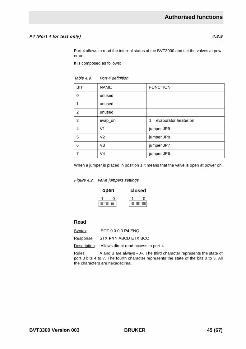
P4 (Port 4 for test only) 4.8.9
Port 4 allows to read the internal status of the BVT3000 and set the valves at pow-er on.
It is composed as follows:
Table 4.9. Port 4 definition
When a jumper is placed in position 1 it means that the valve is open at power on.
Figure 4.2. Valve jumpers settings
Read
Syntax: EOT 0 0 0 0 P4 ENQ
Response: STX P4 > ABCD ETX BCC
Description: Allows direct read access to port 4
Rules: A and B are always «0». The third character represents the state ofport 3 bits 4 to 7. The fourth character represents the state of the bits 0 to 3. Allthe characters are hexadecimal.
BIT NAME FUNCTION
0 unused
1 unused
2 unused
3 evap_on 1 = evaporator heater on
4 V1 jumper JP9
5 V2 jumper JP8
6 V3 jumper JP7
7 V4 jumper JP6
1 0 1 0
open closed
BVT3300 Version 003 BRUKER 45 (67)
Remote interface control
RB (Read BBIS) 4.8.10
Write
Syntax: EOT 0 0 0 0 STX R B adr_e2prom A1 A0 ETX BCC
Response: STX R B > D0 D1 ETX
NACK if command can't issue.
Description: RB command allows to read a single byte in a BBIS E2PROM
Rules: A1, A0 are values from '0' up to 'F' representing the byte address inthe E2PROM.
adr_e2prom is a value from '0' up to '7' representing the I2C bus address ofthe E2PROM
- 0: Address unused
- 1: BVT3X00 motherboard address
- 2: BVTB3500 (Booster) address
- 3: Address unused
- 4: Address unused
- 5: Address unused
- 6: Address unused
- 7: Address unused
All other values generates a NACK response
46 (67) BRUKER BVT3300 Version 003
Authorised functions
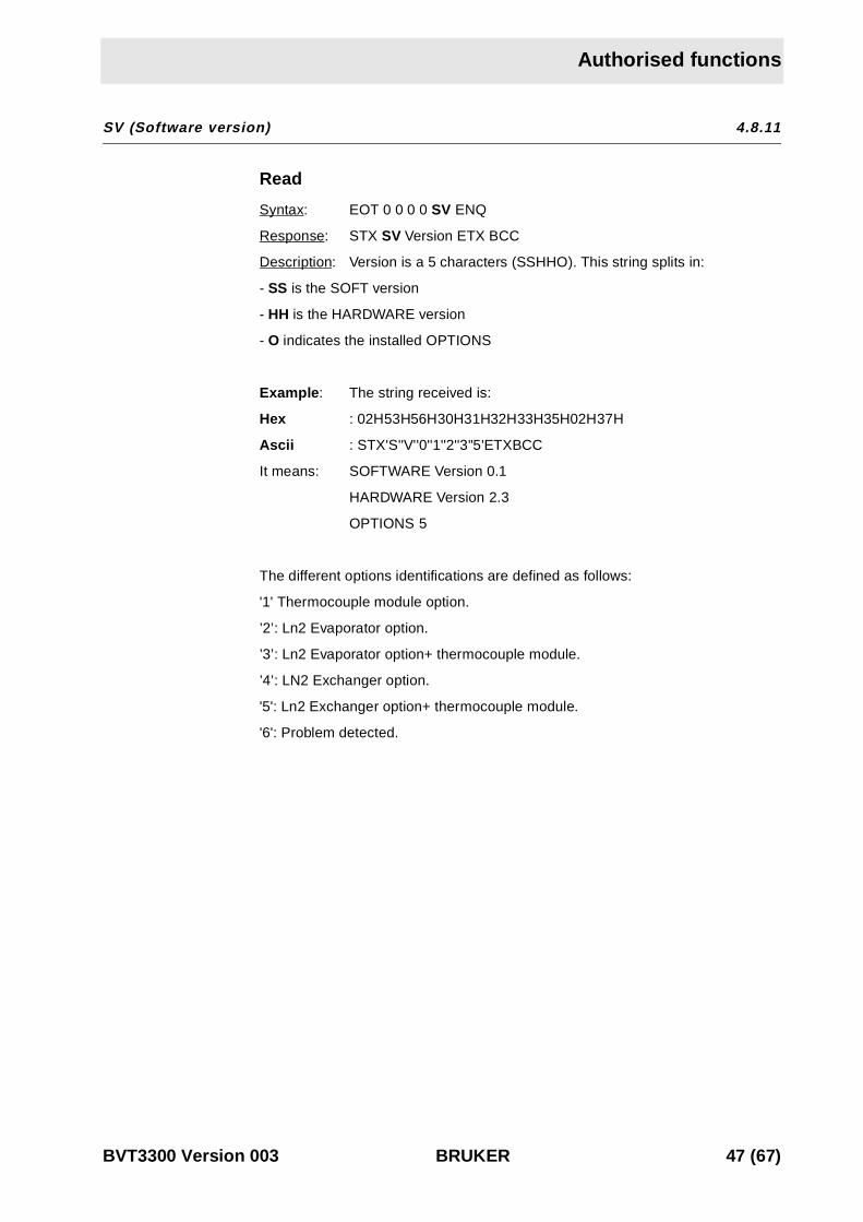
SV (Software version) 4.8.11
Read
Syntax: EOT 0 0 0 0 SV ENQ
Response: STX SV Version ETX BCC
Description: Version is a 5 characters (SSHHO). This string splits in:
- SS is the SOFT version
- HH is the HARDWARE version
- O indicates the installed OPTIONS
Example : The string received is:
Hex : 02H53H56H30H31H32H33H35H02H37H
Ascii : STX'S''V''0''1''2''3''5'ETXBCC
It means: SOFTWARE Version 0.1
HARDWARE Version 2.3
OPTIONS 5
The different options identifications are defined as follows:
'1' Thermocouple module option.
’2’: Ln2 Evaporator option.
’3’: Ln2 Evaporator option+ thermocouple module.
’4’: LN2 Exchanger option.
'5': Ln2 Exchanger option+ thermocouple module.
'6': Problem detected.
BVT3300 Version 003 BRUKER 47 (67)

Remote interface control
WB (Write BBIS) 4.8.12
Write
Syntax: EOT 0 0 0 0 STX W B adr_e2prom A1 A0 D1 D0 ETX BCC
Response: ACK if command issues
NACK in all other cases
Description: WB command allows to write a single byte on a BBIS E2PROM.
Rules: A1, A0 are values from '0' up to 'F' representing the address in theE2PROM.
D1, D0 are values from '0' up to 'F' representing the value to be written.
adr_e2prom is a value from '0' up to '7' representing the I2C bus address ofthe E2PROM
- 0: Address unused
- 1: BVT3X00 motherboard address
- 2: BOOSTER address
- 3: Address unused
- 4: Address unused
- 5: Address unused
- 6: Address unused
- 7: Address unused
All other values generates a NACK response
48 (67) BRUKER BVT3300 Version 003

Authorised functions
WR (Write record) 4.8.13
Intel-Hex format is used to download the firmware on flash-eprom. The file totransfer is generated with OHS51.EXE. Its file extension is «.HEX». This file iscomposed by several records. Each record is composed as shown below:
: L L A A A A T T D D D . . . . . . . . D D C C Cr Lf
Table 4.10. Record format
Write
Syntax: EOT 0 0 0 0 STX TR Rec ETX BCC
Response: ACK if down-load initialized and the record processing issues.
NACK in all other cases
Description: Allows to transfer records extract from a «.hex» file to theBVT3X00.
Rules: Rec value represents an intel-hex record. The first character «:»(3A), Cr and Lf are not transmitted.
FIELD LENGTH SIGNIFICATION
: (3A) 1 Record start
L 2 Record length
A 4 Record address
T 2 Type (00: Data record, 01: EOF record)
D LL Data's
C 2 Checksum
BVT3300 Version 003 BRUKER 49 (67)

Remote interface control
XR (Extract a record) 4.8.14
Write
Syntax: EOT 0 0 0 0 STX X R Val ETX BCC
Response: STX 0 0 0 0 X R Rec BCC
Description: This command is useful to save a working software before to proc-ess a new down-load.
Take care : if Val = 1, regulation is interrupted. Heater, evaporator and gas floware switched off. All the software user function are inaccessible.
Rules: Val = 0: Stops the up-load process.
Val = 1: Initilizes the up-load process.
Val = 2: Autorizes the BVT3X00 to send the next record.
Val = 3: Ask the BVT3X00 to send the same record again.
The up-load process is initialized by receiving «XR1» from the host computer. TheBVT3X00 sends the first Intel-hex record. The BVT3X00 waits then for «XR2» tocontinue. This command autorizes the BVT3X00 to send the next record. Thishandshake continues until the BVT3X00 sends the last record which is «0 0 0 0 00 0 1 F F». Host computer must detect it. Then, BVT3X00 sends an «XR0» re-quests to terminate up-load process and return to normal mode.
If BVT3X00 receives an «XR3» command, the previous record is send again.
An «XR0» Command must be sent to terminate the up-load sequence and returnto normal mode.
50 (67) BRUKER BVT3300 Version 003

5Technicalspecifications 5
5000000 tions
Specifications 5.1
Weight :
• 13 Kg for basic version without any option.
Dimensions :
• 484 (W) x 88 (H) front plate
• 446 (W) x 86 (H) x 500 (D) case
Voltage requirements :
• 220 V + / - 10%, 50/60 Hz
Power consumption :
• 250 VA maximum for standard version.
Inputs:
• Thermocouple type T with standard linearisation.
• Pt100
• BTO2000
Temperature stability :
• temperature controller : Eurotherm 902
• +/- 0.2 °C target temperature = room temperature +5 °C to 200 °C with T ther-mocouple.( Room temperature must not change by more than +/- 1°C ).
• +/- 0.1 °C target temperature = room temperature +5 °C to 50°C withBTO2000.( Room temperature must not change by more than +/- 1°C ).
Heater power :
192 W (48 V max. on 12 ohm probe heater with heater cable )
Gas inlet :
• 4 bars mini, 8 bars maxi (dry air or N2 gas).
Gas flow rate :
• 200 l/h to 2000 l/h with 15 steps
Options
For regulation at low temperature following devices can be used:
BVT3300 Version 003 BRUKER 51 (67)

Technical specifications
• BCU05
• LN2 exchanger
• LN2 evaporator with 200 W heater power.
Security fuses 5.2
Some important electronic functions are fuse protected. To replace a blown fuse,turn off the BVT3000 and disconnect the main power cord. A faulty fuse must al-ways be replaced with the same type.
Table 5.1. Fuses values
Fuses Value Protection for
F1 1 AT +5 V digital
F2 6,3 AT Heater resistor
F3 0,5 AT +15 V analog
F4 0,5 AT -15V analog
F5 0,5 AT +24V valve block
F6 0,5 AT + 15 V BTO2000
52 (67) BRUKER BVT3300 Version 003

6Schematics 6
BVT3300 Version 003 BRUKER 53 (67)
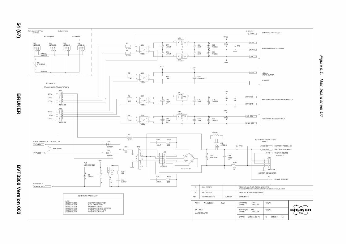
Figure
6.1.M
ainboard
sheet1/7
to sheet 2SYNCHRO THYRISTOR
+/-15V FOR ANALOG PARTS
SYNC
+15P
PGND
P8
+24V dcVALVE SUPPLY
-15P
+24V
to sheet 6
CPUVCC
+15V FOR B-TO2000 SUPPLY
+5V FOR CPU AND SERIAL INTERFACE
CPUGND
+15_BTO
GND_BTO
TO HEATER REGULATIONsheet 2
CURRENT FEEDBACKISENSETP32
VOLTAGE FEEDBACK
THERMOCOUPLE
to sheet 3
12345
J17
41761-05
VSENSE
TC+
HEATER CONNECTOR
FRAME GROUND
H1
PAGES 2, 4, 6 AND 7 UPDATED
ADDED R106, R107, R108 ON SHEET 2MISCELLANEOUS IMPROVEMENTS ON SHEETS 1, 2 AND 5
DRAWN:DATE:
APPROV:DATE:
DWG:
COMMENTS
VISA:
VISA:
SHEET:EW4S11 0276
AKL10/02/95
PK10/02/95
1/7
54(67)
BR
UK
ER
BV
T3300
Versio
n003
1
2
ZD6TVS315
1
2
ZD8TVS315
T
TP22
TP28VI1 VO 2G
ND
3
U517815CT
C5910uF
C6610uF
4
2 3
1RB1
W06M
C771000uF
C751000uF
F3
0.5ATF4
0.5AT
to Transfo
1 2 3
J1441761-03
from MAIN SUPPLY220Vac
to Eurotherm
to LN2 option
1 2 3
J1041761-03
1 2 3
J1141761-03
1 2 3
J1241761-03
1
2
RI1CTN SG40
MAINS1
MAINS3
MAINS2
F5
0.5AT
4
2 3
1RB3
W06M
R95100K
TP33
VI1 VO 2GND
3
U587915CT
C78470uF/50V
+24V
TP29
1
2
ZD1TVS305
TP5
TP6 TP1C310uF
VI1 VO 2GND
3
U87805CT
4
2 3
1RB2
W06M
C241000u16V
F1
1AT
17Vac
AC INPUTS
FROM POWER TRANSFORMER
48Vac123456
J18
41761-06
24Vac
8Vac
17Vac
17Vac
123456
J19
41761-06
F6
0.5AT
4
2 3
1RB4
W06M
C79470uF50V
C4910uF
VI1 VO 2GND
3
U487815CT
TP16
TP9
1
2
ZD2TVS315
5mH/5A
1 2
J1641761-02
C82
100nF
R104
1002 1
D10
1N4007
F2
6.3ATFROM THYRISTOR CONTROLLER
THPULS1
from sheet 2
THPULS2 2 1D11
1N4007
R102100
R96
150
+24V
1
6
3
4
2
5
TR1
IT233
123456
J15
41761-06
2
1D12MUR4100
BF37742-931
R105
47m5W
C833900u100V
D AKL 11/09/95
E AKL 22/01/96
C81
100nF
R103
100C800.33uF
2
1D91N4148
1
8
2 7
3 6
4 5
RL1MZPA0014516
from sheet 6
HEATER_RLY-
|LINKHEATER REGULATION
INTERFACE CPUINTERFACE RS232 ADAPTER
FAULT MONITORS
INTERFACE OUTPUTSINTERFACE INPUTS
SCHEMATIC PAGES LIST
|S110277E.SCH|S110278E.SCH|S110279E.SCH|S110280E.SCH|S110281E.SCH|S110282E.SCH
ART: W1101113
REV MODIFIED/DATE
MAIN BOARD
BVT3x00
EC:
NUMBER

Figure
6.2.M
ainboard
sheet2/7
RESERVED FOR SLAVEGND BTO+15V BTORESERVED FOR -15V
BOOSTER CONNECTOR
SDASCL I2C BUS
+5V CPU
GND CPU
123456789
101112131415
J9
CN MKK15 D
O
PGNDPGND
POWER CONTROL OUTPUT (0 TO 10V)
BUFFERED THERMOCOUPLE VOLTAGE INPUT
BOOSTER CONNECTED IF GROUNDEDBOOSTER HEATER RELAY CONTROL
R48
10k
BOOSTER_CONN-
+15P
to sheet 6,7
FROM TRANSFORMERMAINS SYNCHRONIZATION
R852K
R84221K
50Hz INI_in < 200uA
VSY5
VST8
R9
C10
VCON11
INH6
PULS13
PULS E12
Q1 14
Q2 15
Q1 4
Q2 2
QU 3
QZ 7
U55
TCA785
TP34
TP35
+15P
TO THYRISTOR BRIDGE
to sheet 1
THPULS1THPULS2
IC BYPASS CAPACITORSAND SUPPLY CONNECTIONS
THYRISTOR CONTROLLER
C70150pF
72uF
C67100nF
C68100nF
C55100nF
C64100nF
C45100nF
C52100nF
+15P
-15P
C47100nF
RC4200:
GND = pin 6VEE = pin 3
TCA785:
VCC = pin 16GND = pin 1
VCC = pin 16
4053:
GND = pin 7,8
LM324:
VCC = pin 4VEE = pin 11
DRAWN:DATE:
APPROV:DATE:
DWG:
VISA:
VISA:
SHEET:EW4S11 0277
AKL10/02/95
PK10/02/95
2/7
BV
T3300
Version
003B
RU
KE
R55
(67)
R49
56.2R
GND_BT+15_BTO
SDASCL
CPUVCC
CPUGND
from sheet 1
from sheet 6R5010k
5
67
U47B
LM358N
6
1114
15
4
12
1
3
16 87
13
2
5
10
9
U464053
R4722.1k
VCC
R45
100R
R79
1K
12
1314
U54D
LM324
+15P
from sheet 1HEATER THERMOCOUPLE
GND
R9210M
+15P
-15P
PGND
TC+
VCC
VEE
from sheet 4Power set input from acquisition board
1
2
ZD9TVS315
R78
332K
R77
1K
C69
1uF
TP26
3
21
U47A
LM358N
R36
10k
R35
100k
HEATER_RLY
PGND
+15P
from sheet 1
from sheet 6
R86
82K5
SYNC
12ZD4
BZX55C11
TP31
POWER REGULATION
to sheet 3
7
8RN5DRS4/10K
MUX_TC
R69
10kR31
4K99
R30
10K
R29
10K
3
21
U49A
LM324
FROM EUROTHERM (0-10V)
R22499
12345
J5
6410-05
TP7DAC12_OUT
from sheet 5
TxD
RxD
R42
33K2
R32
33K2
2 1D7
BAT85
5
67
U49B
LM324
TP10
R43
1K
C50
2.2uF
10
98
U49C
LM324
R51
4K99
1 2RN5A
RS4/10K
3 4RN5B
RS4/10K
12
1314
U49D
LM324
C71
47nF
2 1D8
1N4148
R87
2K21
TP23
10V = off0V = max power
C1
R100
249K
R5222.1K
TP18
R97
49K9
R53
10K
R33
5K62
3
21
U53A
LM324
R106
10k
SHUTDOWN INPUT
FROM FAULT MONITORING CIRCUITS
HEATER OUTPUT VOLTAGE
from sheet 3
SHUTDOWN
from sheet 1
R551K15
R544K75
VSENSE
V FEEDBACK
R56
10K
5
67
U53B
LM324
R107
10k
R108
10k
TP19
R98
301K
R91
301K
R101
60K4
+15P
I21
V1 7
I3 4
I18
I45
V2 2
U60
RC4200
POWER FEEDBACK TP25
C65100nF
R75
61K9
R7440K2
R761M5
10
98
U53C
LM324
+15P
R93100
R94
10K
P150KP25T
+15P
VEE
2-QUADRANTMULTIPLIER
R99
249K
R7210k
+15P
R90
49K9
R89
3.01k
I FEEDBACK
R58
1K
R57
56.2k
HEATER OUTPUT CURRENTfrom sheet 1
ISENSE
UNUSED PARTS
141112
109
1513
U59B
4538
+15P
+15P
811910
13
12
U56B
4013+15P OP AMP REFERENCE VOLTAGE
8
910
U57C
4081
12
1311
U57D
4081
C631uF
TP24
12
1314
U53D
LM324R7310k
ART: W1101113
MAIN BOARD
BVT3x00
VREFEC:

Figure
6.3.M
ainboard
sheet3/7
0 = Valve open
to sheet 7
VALVE_EXCH-EXCHANGER VALVE
123
10
U37C
4025
P21
2 1D4
1N4148
R38
10K
to sheet 2
to sheet 7
SHUTDOWN
OVERHEAT
Power controlShutdown
LIGHT OVERHEATING MONITORLIMITS HEATING POWER
2 1D3
1N4148
to sheet 6
Enable Power
to sheet 7
TP14
NO_GAS
POWER_EN-
DEFAULT
2 1D6
1N4148
2 1D5
1N4148
TP27
C4222uF
R3910K
2 1D2
1N4148
+15P
R4010K
DRAWN:DATE:
APPROV:DATE:
DWG:
VISA:
VISA:
SHEET:EW4S11 0278
AKL10/02/95
PK10/02/95
3/7
56(67)
BR
UK
ER
BV
T3300
Version
003
111
EXCH_CONN-
LN2_EMPTY1
23
U38A
4001
R64
301K
LN2_EMPTY-
345
6
U37B
4025
128
9
U37A
4025
from sheet 6
HEATER_RLY
+15P
PGND
-15P
VCC
VEE
VDD
from sheet 2
MUX_TC
R59
301K
R62
6.81k
+15P
R60
10M
3
21
U54A
LM324 JUMPER
R66
100K
R65
10k
R674.32k
R46
4.99k
JP11
+15P
+15P
C53
10uF
C57
10uF
T
5
67
U54B
LM324
HEAVY OVERHEATING
4.5V8.5VPLACED:
REMOVED:
TP20
R635.11k
6.4V9.3V
JUMPER
PLACED:REMOVED:
R61
5.62k
JP12
+15P
R7010K
+15P
EVAPORATOR OR EXCHANGERN2 LEVEL SENSOR
from sheet 7
from sheet 6
HEATER_CTRL-
EVAP_CTRL-
LN2_EMPTY- LN2_EMPTY- NITROGEN LEVEL MONITOR
RESETS DEFAULT LATCHES
1
2
ZD7TVS315
1
23
U52A
4001
DEFAULTS04
R03
S16
R17
S212
R211
S314
R315
EN5
Q0 2
Q1 9
Q2 10
Q3 1
U50
4043
+15P
R83
10K
TP30
+15P21D1
1N4148
5
64
U52B
4001
TP12
1
23
U57A
4081
12
1311
U52D
4001
8
910
U52C
4001
from sheet 6
LN2 OPTION CONNECTED
from sheet 7
EVAP_CONN-
EXCH_CONN- EXCH_CONN-
from sheet 6
from sheet 7
5
64
U38B
4001
R88
511K
HEATER_RLY
LN2_EMPTY
+15P 254
67
13
U59A
4538
GAS FLOWSENSOR
6354
1
2
U56A
4013
+15P
1234
J6
6410-04
R411K21
+15P
C74100uF
R82
22K1JP10
BREAKS UP HEATINGGAS FLOW MONITOR
R81
10K10
98
U54C
LM324
R80
1M
VREF
Inhibit Gas Flow Detectionwhen placed
INHIBITS GAS FLOWDURING 2.5s WHENEXCHANGER CONNECTED
+15P
IC SUPPLIES:
C764.7u35V
LM324:
4043,
4001, VCC = pin 14GND = pin 7
VCC = pin 16GND = pin 8
VCC = pin 4GND = pin 11
4081,4013,
4538:
4025:
C54 C58 C38
9 X 100nF
C56 C60 C62 C37 C73
+15P
ART: W1101113
MAIN BOARD
BVT3x00
C61
EC:

Figure
6.4.M
ainboard
sheet4/7
CHARGE PUMP
C4220n
C5220nSHDN8
C1+ 2
C1- 1
VCC 5
GND 7VOUT6
C2+ 4
C2- 3
U7
MAX662
D0D1D2D3D4D5D6D7
D[0..7]
FLASH_VPON-
A1A2A3A4A5A6A7
A12
A8A9A10A11
A15
A13A14
NC 2
CEOE
O0 13
O1 14
O2 15
O3 17
O4 18
O5 19
O6 20
O7 21
VPP 1
A0
WE
NC 30
U2
28F512PLCC
A0A1A2A3A4A5A6A7A8A9A10A11A12A13A14
A15 2
CEOE
O0 13
O1 14
O2 15
O3 18
O4 19
O5 20
O6 21
O7 22
NC 1NC 12NC 17NC 26
U1527512PLCC
FLASH
C194.7u
R6
10R
C17
100nC18100u
VCC
0000h - FFFFh
32k OR 64kBOOT EPROM
D0D1D2D3D4D5D6D7
D[0..7]
VTS10/01
A0A1A2A3A4A5A6A7A8A9A10A11A12A13A14
CSOEWE
D0 11
D1 12
D2 13
D3 15
D4 16
D5 17
D6 18
D7 19
U11
D43256C
R162.21k
D0D1
A15
VCC
A
B = 27256
= 27512
JP5
0000h - 7FFFh
SRAM 32k*8
D2D3D4D5D6D7
A0A1A2A3A4A5A6A7A8A9A10
CEOEWE
D0 9
D1 10
D2 11
D3 13
D4 14
D5 15
D6 16
D7 17
U17
X2816AP
D0D1D2D3D4
9000h - 97FFh
EEPROM 2k*8
D5D6D7
DRAWN:DATE:
APPROV:DATE:
DWG:
VISA:
VISA:
SHEET:EW4S11 0279
AKL10/02/95
PK10/02/95
4/7
BV
T3300
Version
003B
RU
KE
R57
(67)
111098765
4
27262325
3
2829
2224
12
31
A0A1A2A3A4A5A6A7A8A9A10
DATA BUS
to sheet 5,6,7
111
23456789
1918171615141312
U20
74HC573
D[0..7]
ALE
D[0..7]
EA/VP35
X121
X220
RESET10
P3.2/INT014
P3.3/INT115
P3.4/T016
P3.5/T117
P1.0/T22
P1.1/T2X3
P1.24
P1.35
P1.46
P1.57
P1.68
P1.79
P0.0 43
P0.1 42
P0.2 41
P0.3 40
P0.4 39
P0.5 38
P0.6 37
P0.7 36
P2.0 24
P2.1 25
P2.2 26
P2.3 27
P2.4 28
P2.5 29
P2.6 30
P2.7 31
RD 19
WR 18
PSEN 32
ALE/P 33
TXD 13
RXD 11
NC1
NC12 NC 23NC 34
U13
80C32PLCC
D0D1D2D3D4
C11
18pF
C12
18pF
X1
11.059M
2345
1RP1
4.7k
VCC
FROM UART
sheet 5
BOOT
1 0JP2
INTR-
PGMODE
1 0JP3
1234567891011121314151617181920212223242526
J2CN M CPLL26 D
BOOTPGMODE
FLASH_VPON-INTR-
D5D6D7
RD-
A8A9A10A11A12A13A14A15
ADDRESS LATCH
RD-
D7D6D5D4D3D2D1D0
11109876542928242733031
2325
A0A1A2A3A4A5A6A7 A11
A12A13A14A15
CS_FLASH-RD_FLASH-WR_FLASH-
A0A1A2A3A4A5A6A7A8A9A10A11A12
to sheet 5
WR-
A[0..2]
RxD2TxD2
A[0..2]
ALE
WR-PSEN-
TxD_2RxD_2SCL
SDA
+15P
RESET-
VCC
PGMODE BOOT MODE
0 X1 0 RUN EPROM ONLY1 1
RUN FLASH PROGRAM ONLY
NORMAL MODE
1 2
U12A
74HCT14
to sheet 5
ACQUISITION BOARD
R710K
RESET
VCC
sheet 1+/-15V
BTO2000supply
sheet 6
DAC12_OUT
-15P
PGND
+15_BTOGND_BTOSCLSDAAUX1 1
23
U18A
74HCT32
WR-
CSPORT1
to sheet 5
to sheet 6
8000h - 8FFFh
9000h - 9FFFh
A000h - AFFFh
CS50-
WRPORT1-
CS_E2PR-
109876543252421232261
202227
A0A1
A13A14
A[0..15]
CS_ROM-PSEN-
A2A3A4A5A6A7A8A9A10A11A12A13A14to sheet 7
to sheet 6B000h - BFFFh
C000h - CFFFh
WRPORT2-
RDPORT3-
4
56
U18B
74HCT32
9
108
U18C
74HCT32
WR-
RD-
CSPORT2
CSPORT3
ADDRESS DECODER
12
645
1514131211109
3
7
U14
74HCT138
CONNECTOR
R144K75
A15
A12A13A14
RST 7WDI6
GND4
VCC1
U4
MAX699
TP2
VCC
I11
I22
I33
I44
I55
I66
I77
I88
I99
I10 11
IO1 19
IO2 18
IO3 17
IO4 16
IO5 15
IO6 14
IO7 13
IO8 12
VCC 20
DGND10
U3
EP330
RESET-
to sheet 6
RESET-
VCC
12
1311
U18D
74HCT32
RD-
CSPORT4
VCC
to sheet 7E000h - EFFFh
RDPORT4-
87654321232219
182021
RD-WR-
A0A1A2A3A4
CS_RAM-
A5A6A7A8A9A10
WR-RD-CS_E2PR-
C22 C26 C29
C20 C8 C6 C25
ONE 100nF BYPASS CAPACITOR PER IC
C23 C28
C7 C31
VCC
IC SUPPLIES:
74HC14:74LS32:
74LS138:
74ALS573:
DGND = pin 7
DGND = pin 8
DGND = pin 10
VCC = pin 14
VCC = pin 16
VCC = pin 20
CS_RAM-CS_ROM-
CS_FLASH-
RD_FLASH-
WR_FLASH-
IOENA-
WDI-
ALE
VTS10/02
PGMODE
A14A15
RD-WR-
PSEN-
A13A12
4
56
U1B
74LS32
CS_ROM-
BOOT PROGRAM RUNNING
R1
332R
1
2LD1
VCC
80C32:
27512:
D43256C:
X2816:
DGND = pin 22
DGND = pin 16
DGND = pin 14
DGND = pin 12
VCC = pin 44
VCC = pin 32
VCC = pin 28
VCC = pin 24 from sheet 1INTERFACE +5V
+5VCPUVCC
CPUGND
DGND
ART: W1101113
MAIN BOARD
BVT3x00
VCC EC:
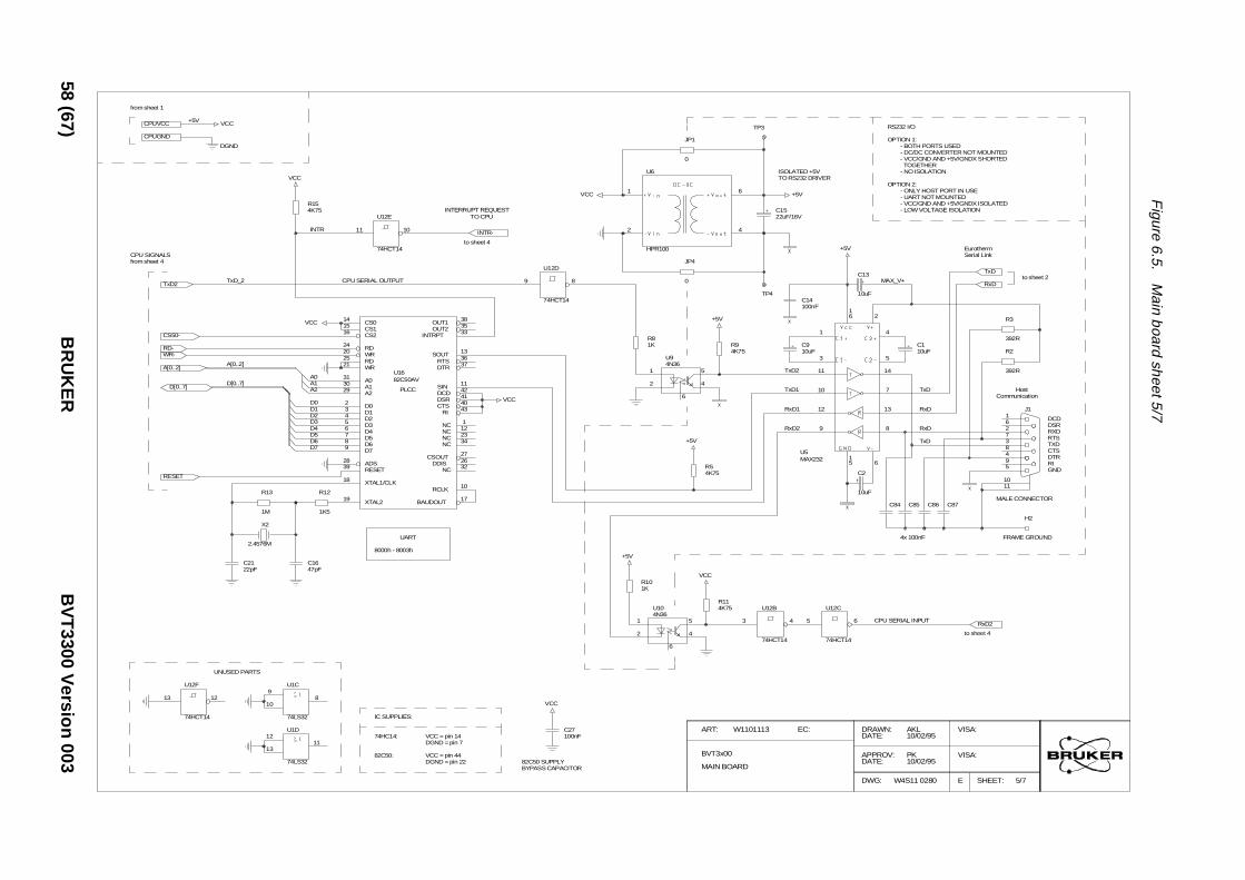
Figure
6.5.M
ainboard
sheet5/7
RS232 I/O
OPTION 1:- BOTH PORTS USED- DC/DC CONVERTER NOT MOUNTED- VCC/GND AND +5V/GNDX SHORTEDTOGETHER
- NO ISOLATION
Eurotherm
OPTION 2:- ONLY HOST PORT IN USE- UART NOT MOUNTED- VCC/GND AND +5V/GNDX ISOLATED- LOWVOLTAGE ISOLATION
Serial Link
to sheet 2
R3
392RC110uF
RxD
TxD
MAX_V+C13
10uF
2
4
5
6
8
13
7
14
TxD
RxD
Communication
RxD
Host
DCDDSRRXD
R2
392R
594837261
1110
J1
RTSTXDCTSDTRRIGND
H2
TxD
MALE CONNECTORC84 C85 C86 C87
C2
10uF
6
4x 100nF FRAME GROUND
to sheet 4
CPU SERIAL INPUTRxD2
DRAWN:DATE:
APPROV:DATE:
DWG:
VISA:
VISA:
SHEET:EW4S11 0280
AKL10/02/95
PK10/02/95
5/7
58(67)
BR
UK
ER
BV
T3300
Version
003
ISOLATED +5V
TP3
1
2
6
4
U6
HPR100
JP1
0
from sheet 1
+5V
DGND
CPUVCC
CPUGND
VCC
from sheet 4CPU SIGNALS
R154K75
INTR
VCC
to sheet 4
INTERRUPT REQUESTTO CPU
11 10
U12E
74HCT14
INTR-
VCC
JP4
0
TO RS232 DRIVER
C1522uF/16V
+5V
+5V
C910uF
C14100nF
16
1
3
11
10
12
9
15
U5MAX232
TP4
R81K R9
4K75
+5V
9 8
U12D
74HCT14
CS014
CS115
CS216
RD24
WR20
RD25
WR21
A031
A130
A229
D02
D13
D24
D35
D46
D57
D68
D79
ADS28
RESET39
XTAL1/CLK18
OUT1 38
OUT2 35
INTRPT 33
SOUT 13
RTS 36
DTR 37
SIN 11
DCD 42
DSR 41
CTS 40
RI 43
NC 1
NC 12
NC 23
NC 34
CSOUT 27
DDIS 26
NC 32
BAUDOUT 17
RCLK 10
XTAL219
U1682C50AV
CPU SERIAL OUTPUT
VCC
TxD_2
CS50-
RD-
TxD2
WR-
A[0..2]
D[0..7]
A[0..2]
D[0..7]
D0D1D2D3D4D5
A0A1A2 PLCC
VCC
1
2 4
5
6
U94N36
TxD2
TxD1
RxD1
RxD2
R54K75
+5V
R12
1K5
R13
1M
D6D7
RESET
C2122pF
C1647pF
X2
2.4576MUART
8000h - 8003h
R101K
R114K75
VCC
+5V
5
U12C
74HCT14
3 4
U12B
74HCT14
1
2 4
5
6
U104N36
9
108
U1C
74LS32
UNUSED PARTS
13 12
U12F
74HCT14
12
1311
U1D
74LS32
IC SUPPLIES:
74HC14:
82C50:
VCC = pin 14
VCC = pin 44
DGND = pin 7
DGND = pin 22BYPASS CAPACITOR82C50 SUPPLY
C27100nF
VCC
ART: W1101113
MAIN BOARD
BVT3x00
EC:

Figure
6.6.M
ainboard
sheet6/7to sheet 3
LED -LED +
SWITCHFRONT-PANELHEATER SWITCH
1 2ZD5
10V
R68
1.5K
123456
J7
CN MKK06 D6410-06
HEATER_CTRL-
EVAP_CTRL-
16
9U44A
+24V
15
9
HEATER ON/OFF
EVAPORATOR ON/OFFTP11
HEATER_RLY-
HEATER_RLY
EVAP_ON-
to sheet 1
to sheet 7
to sheet 2, 3, 7
VALVE1
VALVE2
VALVE CONNECTOR
123456789
10
J8
6410-10
TP13
TP17
+24V
14
9
13
9
12
9
11
9
004
TP15
VALVE3
VALVE4
to sheet 7
LN2 POWER LEVEL CONTROL
SPARE PART
DAC
FC48100nF
IC SUPPLIES:
74HCT273:
7 10
9U44G
ULN2004
DGND = pin 10VCC = pin 20
VDD = pin 8VSS = pin 4
VDD = pin 14
GND = pin 3
GND = pin 8
GND = pin 7
VDD = pin 14
VCC = pin 8DGND = pin 4
AD7523:
TL072:
ULN2004:
4001, 4081:
X24022:
DRAWN:DATE:
APPROV:DATE:
DWG:
VISA:
VISA:
SHEET:EW4S11 0281
AKL10/02/95
PK10/02/95
6/7
BV
T3300
Version
003B
RU
KE
R59
(67)
1
R7122.1k
5
64
U57B
4081
from sheet 2
8
910
U38C
4001
BOOSTER_CONN-
2 3 4 5 6 7 8 9
1RP4RS8A/10K
+15P
I2C CONNECTOR
to sheet 2,4
to sheet 2,4
12
J3
CN MKK02 D
SDA
SCL
R23
4.75k
VCC
HEATER & LN2 POWER ENABLE
from sheet 3
BBIS EEPROMR18
4.75k A01
A12
A23
SCL6
NC7
SDA 5U24
X24022
POWER_EN-
VCC
TO J2
1
2 8
7
U25A
4
3 5
6
U25B
12RN2A
78RN2DRS4/390
AUX1
HEATER_CTRL-
EVAP_CTRL-
12
1311
U38D
4001
2
U44B
3
U44C
4
U44D
5
U44E
1
23
U39A
4001
5
64
U39B
4001
8
910
U39C
4001
VALVE2
VALVE1sheet 4
4
3 5
6
U26B
1
2 8
7
U26A
1
2 8
7
U27A
12RN3A
3 4RN3B
5 6RN3C
HEATER
VALVE1VALVE2VALVE3VALVE4
EVAPORATORAUX1
from sheet 4
111
347813141718
2569
12151619
U19
74HCT273
WRPORT1-
D0D1D2D3D4D5D6D7
RESET-
WRITE PORT1 - A000h
from sheet 4
POWER-ON RESET
RESET-RESET-
D[0..7]
1
2 8
7
U28A
4
3 5
6
U27B
MCT6
12RN1A
RS4/390
7 8RN3D
RS4/390
VALVE3
VALVE4
+15P
12
1311
U39D
4001
6
U44F
ULN2
R25
10KR34
10K
C43100pF
3
21
U45A
TL072
B011
B110
B29
B38
B47
B56
B65
B74
RFB16
VREF15
CS12
WR13
O1 1
O2 2
U40
AD7523OR AD7524
DAC0
DAC1
DAC2
DAC3
DAC0DAC1DAC2DAC3DAC4DAC5DAC6DAC7
REF_DAC
1
2 8
7
U29A
34RN1B
RS4/390
56RN1C
RS4/390
78RN1D
RS4/390
4
3 5
6
U28B
4
3 5
6
U29B
1LN22LN23LN24LN2
from sheet 4
111
347813141718
2569
12151619
U21
74HCT273
WRPORT2-
D0D1D2D3
WRITE PORT2 - B000h
D[0..7]
D4D5D6D7
5LN26LN27LN28LN2
1
2 8
7
U30A
1
2 8
7
U31A
12RN4A
RS4/390
34RN4B
RS4/390
56RN4C
RS4/390
78RN4D
RS4/390
4
3 5
6
U30B
4
3 5
6
U31B
MCT6
DAC4
DAC5
DAC6
DAC2DAC3DAC4DAC5DAC6DAC7
23456789
1
RP6
RS8A/10K
C46100nF
C40100nF
C39100n
+15P
C44100nF
-15P
SUPPLY BYPASS CAPACITORSLM301, AD7523, CD4001, CD4081
REF_DAC1 2ZD3
BZX55C10V
C51
100pF
DAC7 DAC0DAC1
VCC
from sheet 1
from sheet 4
+5VCPUVCC
CPUGND
VCC
DGND
+15P
PGND
-15P
+24V
VDD
VSS
+24V
74HCT273, X24022 BYPASS CAPACITORS
C30100nF
C32100nF
C33100nF
R44
7.5K 5
67
U45BTL072
+15P
(-10V)
ART: W1101113
MAIN BOARD
BVT3x00
EC:

Figure
6.7.M
ainboard
sheet7/7CPU SIDE
BCU05 CONNECTOR
123
J4
CN MKK03 D
R4
100R
from sheet 4READ STROBE
119
2468
11131517
181614129753
U23
74HCT244
RDPORT3-
D[0..7]
to sheet 4
CPU DATA BUS
D[0..7]
HEATER ON
OVERHEATINGEXCHANGER CONNECTED
NO GASEVAPORATOR CONNECTED
LN2 REFILL
BOOSTER CONNECTED
LN2 EMPTY
D0D1D2D3D4D5D6D7
READ PORT3 - C000h
from sheet 4READ STROBE
119
2468
11131517
181614129753
U22
74HCT244
RDPORT4-
UNUSED
EVAPORATOR ONVALVE1VALVE2VALVE3VALVE4
EXCHANGER VALVE CLOSEDD0D1D2D3D4D5D6D7
READ PORT4 - E000h
THE GAS FLOWAT POWER ONTHE JUMPERS PRESET
EVAP_CONN-
EXCH_CONN-
LN2_EMPTY-
to sheet 3
C10100nF
VCC
74HCT244 BYPASS CAPACITOR
C34100nF
VCC
DRAWN:DATE:
APPROV:DATE:
DWG:
VISA:
VISA:
SHEET:EW4S11 0282
AKL10/02/95
PK10/02/95
7/7
60(67)
BR
UK
ER
BV
T3300
Version
003
TO PORT 4
1
23
U1A
74LS32
EVAPORATOR HEATER STATUS
IN0
I_EVAP_STAT
I_VALVE
PLP7PLP6
PLP5PLP4
PLP3PLP2
PLP1PLP0
+15P
23456789
1RP5
RS8A/2K7
+15P
DGND
+5V VCC
from sheet 1
CPUVCC
CPUGND
+15P
PGND
-15P
+24V
VDD
VSS
+24V
from sheet 3
VALVE_EXCH-
EVAP_STAT-
R20
10K
R26
10K
+15P
+15P
3
21
U41ALM358
5
67
U41BLM358
VREF
1
2 8
7U32A
MCT6
4
3 5
6U32B
MCT6
R242K74
R212K74
2 3 4 5 6 7 8 9
1
RP3RS8A/4K7
VCC
IN0IN1IN2IN3IN4IN5IN6IN7
IN0
IN1
1
2 8
7U33A
MCT6
4
3 5
6U33B
MCT6
1
2 8
7U34A
MCT6
PLP0
PLP1
3
21
U42ALM324
5
67
U42BLM324
R27
10K
from sheet 6
HEATER POWER ON
from sheet 2
HEATER_RLY
BOOSTER_CONN-
LIGHT OVERHEATING
NO GAS FLOW
from sheet 3
NO_GAS
OVERHEAT
EVAP_CONN-
+15P 10
98
U42CLM324
12
1314
U42DLM324
3
21
U43ALM324
4
3 5
6U34B
MCT6
1
2 8
7U35A
MCT6
PLP2
PLP3
PLP4
2 3 4 5 6 7 8 9
1RP24.7k
IN2
IN3
IN4
from sheet 6
SDA
VCC
JP6 JP7 JP8 JP9
I_EVAP_STAT
I_VALVE
IN5
IN6
4
3 5
6U35B
MCT6
1
2 8
7U36A
MCT6
PLP5
PLP6
5
67
U43BLM324
10
98
U43CLM324
R28
10K
R37
10K
+15P
+15P
from sheet 3
EXCH_CONN-
REFILL-
12
1314
U43DLM324
4
3 5
6U36B
MCT6
PLP7
0
1
V4
IN7
0
1
V3 V2 V1
VDD = pin 8
VDD = pin 4
DGND = pin 10VCC = pin 20
GND = pin 4
GND = pin 11
IC SUPPLIES:
74HCT244:
LM358:
LM324:
C36C35
+15P
C41
123456789
1011121314
J13
6410-14
EVAP_CONN-
LN2_EMPTY-
EXCH_CONN-
REFILL-EVAP_STAT-
+15P-15P
from sheet 6
EVAP_ON-
from sheet 3
DAC
VALVE_EXCH-
OPTION CONNECTOR
+24V
LM358, LM3243X100nF BYPASS CAPACITORS
ART: W1101113
MAIN BOARD
BVT3x00
EC:

Figure
6.8.M
ainboard
layout
BV
T3300
Version
003B
RU
KE
R61
(67)

Schematics
62 (67) BRUKER BVT3300 Version 003

Figures
1 Description 7Figure 1.1. BVT3300 block diagram .........................................................8Figure 1.2. Parts location ........................................................................9Figure 1.3. BVT3300 front panel ............................................................10Figure 1.4. Gas flow circuit ....................................................................11Figure 1.5. Heater connector (Front view) ..............................................13Figure 1.6. Pt100 connector (front view) ...............................................14Figure 1.7. Thermocouple connector (Front view) .................................15Figure 1.8. RS232 male connector (Front view) .....................................16Figure 1.9. N2 connector (Front view) ....................................................17Figure 1.10. BCU05 connector ................................................................17Figure 1.11. BVTB 3500 connector (Front view) ......................................18
2 Options 19Figure 2.1. BASM front view ..................................................................19Figure 2.2. BMCM Front view ................................................................20Figure 2.3. Exchanger principle .............................................................21Figure 2.4. Evaporator principle ............................................................22Figure 2.5. BCU05 principle ..................................................................23
3 Configuration 25
4 Remote interface control 27Figure 4.1. RS232 cable. .......................................................................30Figure 4.2. Valve jumpers settings .........................................................45
5 Technical specifications 51
6 Schematics 53Figure 6.1. Main board sheet 1/7 ...........................................................54Figure 6.2. Main board sheet 2/7 ...........................................................55Figure 6.3. Main board sheet 3/7 ...........................................................56Figure 6.4. Main board sheet 4/7 ...........................................................57Figure 6.5. Main board sheet 5/7 ...........................................................58Figure 6.6. Main board sheet 6/7 ...........................................................59Figure 6.7. Main board sheet 7/7 ...........................................................60Figure 6.8. Main board layout ................................................................61
BVT3300 Version 003 BRUKER 63 (67)

64 (67) BRUKER BVT3300 Version 003

Tables
1 Description 7Table 1.1. Flow rate versus command ............................................ 12Table 1.2. Heater connector pin assignment ................................... 13Table 1.3. Pt100 connector pin assignment .................................... 14Table 1.4. Thermocouple T pin assignment .................................... 15Table 1.5. Rs232 connector pin assignment ................................... 16Table 1.6. Evaporator connector pin assignment ........................... 17Table 1.7. BCU05 connector pin assignment ................................. 17Table 1.8. BVTB 3500 connector pin assignment ........................... 18
2 Options 19
3 Configuration 25Table 3.1. Eurotherm 847 sensor selection ..................................... 26Table 3.2. CJC selection ................................................................ 26
4 Remote interface control 27Table 4.1. Control characters. ........................................................ 28Table 4.3. Authorised commands .................................................. 31Table 4.4. Error status description .................................................. 37Table 4.6. Port 1 definition ............................................................. 42Table 4.7. Port2 definition .............................................................. 43Table 4.8. Port3 definition .............................................................. 44Table 4.9. Port 4 definition ............................................................. 45Table 4.10. Record format ................................................................ 49
5 Technical specifications 51
6 Schematics 53
BVT3300 Version 003 BRUKER 65 (67)

66 (67) BRUKER BVT3300 Version 003

BVT3300 Version 003 BRUKER 67 (67)
Lastpage