Embed Size (px)
Citation preview

Journal of Power Electronics, Vol. 14, No. 6, pp. 1243-1253, November 2014 1243
http://dx.doi.org/10.6113/JPE.2014.14.6.1243 ISSN(Print): 1598-2092 / ISSN(Online): 2093-4718
JPE 14-6-18
Variable Coefficient Inductance Model-Based Four-Quadrant Sensorless Control of SRM
Song-Yan Kuai†, Xue-Feng Li*, Xing-Hong Li*, and Jinyang Ma*
†*School of Information and Electrical Engineering, China University of Mining and Technology, Xuzhou, China
Abstract
The phase inductance of a switch reluctance motor (SRM) is significantly nonlinear. With different saturation conditions, the
phase inductance shape is clearly changed. This study focuses on the relationship between coefficient and current in an inductance model with ignored harmonics above the order of 3. A position estimation method based on the variable coefficient inductance model is proposed in this paper. A four-quadrant sensorless control system of the SRM drive is constructed based on the relationship between variable coefficient inductance and rotor position. The proposed algorithms are implemented in an experimental SRM test setup. Experimental results show that the proposed method estimates position accurately in operating two/four-quadrants. The entire system also has good static and dynamic performance. Key words: Four-quadrant, Rotor position estimation, Switch reluctance motor, Variable coefficient inductance model
I. INTRODUCTION Switched reluctance motors (SRMs) have the advantages
of simple and firm structure, high efficiency, wide speed range, and high starting torque [1]. However, high-performance control of SRM needs to detect the rotor position with a position sensor attached to the motor shaft. The use of position sensors increases cost and machine size as well as decreases reliability. Therefore, the sensorless drive technique has high research value [2], [3].
SRMs without position sensor technology have aroused widespread concern in recent years. Many scholars have proposed a series of control schemes for position estimation. Most of them infer the instantaneous position of the rotor by measuring and monitoring one phase or several phases of the windings current and flux linkage. The flux-current method takes advantage of the relationship between the rotor position, flux linkage, and phase current [4]-[6]. However, the method is generally achieved by look-up table, which consumes a large amount of memory. Indirect position sensing is implemented by comparing the estimated flux linkage and pre-stored flux linkage of reference commutation position [7].
The proposed method greatly decreases the need for microcontroller memory and capacity. However, continuous position estimation is impossible with this method. Achieving high-grade performance and dynamic torque control continuous position estimation is a requirement. State observer methods are used to estimate rotor position and velocity [8]-[11]. The main disadvantages of these methods are real-time implementation of complex algorithms that require high-speed DSP and a significant amount of stored data. Based on the limitation of the traditional methods above, many scholars have proposed several new methods. The rotor position-estimated algorithms are implemented based on ANN [12]-[15]. Although the position estimator based on ANN above does not need an accurate SRM model and can theoretically provide good nonlinear mapping between input data and output data sets, it is a computation-intensive algorithm. Offline training of the synopsis weights is a rigorous procedure. Phase inductance expressed by the Fourier series, relation between the rotor electrical angle, and inductance can be derived [16], [17]. A position estimation method of calculating the rotor position in real time by the measured inductance is then proposed. The method is relatively easy to implement, simple, and reliable. However, the authors use pulse injection method in a non-energized phase to detect the phase inductance, which inevitably decreases the torque and efficiency of SRM and is unsuited for higher speed applications. The inductance of the
Manuscript received Oct. 6, 2013; accepted Jul. 10, 2014 Recommended for publication by Associate Editor Dong-Hee Lee.
†Corresponding Author: [email protected] Tel: +86-516-83884395, China Univ. of Mining and Technology
*School of Information and Electrical Engineering, China University of Mining and Technology, China
© 2014 KIPE

1244 Journal of Power Electronics, Vol. 14, No. 6, November 2014
energized phase is calculated by dividing the flux linkage by phase current. This method overcomes the defects in [16]-[17], but the authors do not analyze the change trends of model coefficients with inductance saturation. However, this part has an important significance on the accuracy of rotor position estimation. The regional comparison of the three-phase inductance method is proposed [19]. The method is based on the logic relationship of phase inductance that varies regionally with the change in rotor position and is easy to implement. However, the regional comparison method suffers from the influence of inductance saturation and can introduce position estimation errors in dynamic operation. The phase current slope difference based calculation method is utilized to identify the full-cycle inductance [20]. The position versus inductance characteristics is modeled to estimate the rotor position based on the inductance characteristics. However, the method can be applied in light load or no-load conditions only. When the motor is operating in the saturation region, the method has certain limitations.
This paper presents the relationship between coefficient and current in the inductance model. A rotor position estimation method based on the variable coefficient inductance model is then presented. Using this method, we construct the SRM control system and verify the proposed method. Experimental results show that the proposed method is feasible.
II. SIMPLIFIED INDUCTANCE MODEL
A. SRM Structure and its Characteristics The structure of a three-phase SRM is shown in Fig. 1. The
measured flux-linkage versus current characteristics of the three-phase SRM at different rotor positions are shown on the left side of Fig. 2. Fig. 2 shows that the machine saturates at approximately 12 A.
aL is the aligned position inductance, uL is the unaligned
position inductance, and mL is the inductance midway from
the aligned position. aL and mL are related to the phase
currents by functions that can be easily calculated by dividing the flux linkage by the phase current.
( )
( )= aa
iL ii
y (1)
( )
( )= uu
iL ii
y (2)
( )
( )= mm
iL ii
y (3)
B. Coefficients of the Simplified Inductance Model for Different Currents
The solid line in Fig. 3 represents inductance as a function of position for different currents obtained by the
Fig. 1. Structure of a 12/8 SRM.
L
= aaL
iY
= uuL
iY
= mmL
iY
022.500 045 mq
0o5o7o9o11o13o15o17o22.5o
Fig. 2. Magnetization curve and corresponding position of phase inductance.
0 10 20 30 40 50 60 70 80 900
0.02
0.04
0.06
0.08
0.1
Fig. 3. Measured phase inductance (solid line) and reconstructed phase inductance (dashed line).
magnetization curve measured from the locked-rotor test. 0 elec. deg. is defined as the position where the rotor and stator poles of B-phase are unaligned. The measured phase inductance can be represented by the Fourier series as follows:
0
cos ( )n r nL L nN q f¥
= S + (4)
where rN is the number of rotor poles, nL is the coefficients
of the Fourier series, and nf is the initial phases of the Fourier series. Considering the first three components (n = 0, 1, 2) of the Fourier series in Eq. (4), each phase inductance is described by the following equations [17]:
0 1 22 2cos ( ) cos 2( )3 3A elec elecL L L Lp q p p q p= + - + + - + (5)
0 1 2cos( ) cos 2( )B elec elecL L L Lp q p q= + - + - (6)
0 1 2
4 4cos ( ) cos 2( )3 3C elec elecL L L Lp q p p q p= + - + + - + (7)
0L , 1L , and 2L can be derived as a function of the
maximum inductance aL , minimum inductance uL , and
middle inductance mL from Eqs. (8), (9), and (10).

Variable Coefficient Inductance Model-Based … 1245
5 10 15 20 25 30 35 400
0.01
0.02
0.03
0.04
0.05
Fig. 4. 0L , 1L , and 2L vs. current.
+-
sU
1TV
2TV1DV
2DVkU
+-
sU
1TV
2TV1DV
2DVkU
+-
sU
1TV
2TV1DV
2DVkU
1ks = 0ks = 1ks = -
Fig. 5. Phase conduction sequences.
TABLE I COEFFICIENT VALUES OF POLYNOMIAL (H)
Ln A0 A1 A2 A3 A4 A5
L0 0.044 7 0.001 2 ˗1.25e˗4 3.28e˗6 ˗3.48e˗8 1.24e˗10
L1 0.035 1 0.002 8 ˗2.8e˗4 8.84e˗6 ˗1.23e˗7 6.35e˗10
L2 0.005 2 1.415e˗4 ˗2.667e˗5 9.19e˗7 ˗1.3e˗8 6.69e˗11
01 1( ) { ( ( ) ( )) ( )}2 2 a u mL i L i L i L i= + + (8)
11( ) ( ( ) ( ))2 a uL i L i L i= - (9)
21 1( ) { ( ( ) ( )) ( )}2 2 a u mL i L i L i L i= + - (10)
where elecq is the electrical angle, and the relationship
between the electrical angle and mechanical angle mq can be expressed as the following equation: elec r mNq q= (11)
0L , 1L , and 2L are calculated according to Eqs. (8), (9), and (10) from 5A-60A for every 1 A current increments. The obtained numerical result for every point is shown in Fig. 4 as a solid line. Using a fitting tool, 0L , 1L , and 2L are related to the phase currents by polynomial functions given by
0
( )N
kn k
k
L i A i=
=å (12)
where “k” is the degree of approximation (in the present case, 5N = yields good accuracy). Fig. 4 shows the
corresponding curve fit of 0L , 1L , and 2L as well as the actual coefficients calculated from experimental results for
the actual machine. The fifth-degree polynomial can be expressed as the following equation:
5 4 3 25 4 3 2 1 0( ) + ( 0,1,2)nL i A i A i A i A i A i A n= + + + + = (13)
The measured inductance and reconstructed inductance from the simplified inductance model are shown in Fig. 3. The polynomial coefficients are shown in Table I.
III. PRINCIPLE OF THE ROTOR POSITION ESTIMATION BASED ON THE INDUCTANCE
MODEL
A. Calculation of the Phase Inductance and Position Estimation The phase inductance is needed to estimate the rotor
position in the proposed method. The integral form of the voltage equation is provided by the next equation.
0
( ) ( , , )T
k k ku Ri dt k A B Cy = - =ò (14)
where ku is the age, R is the coil resistance, kY is the flux
linkage, and T is the flux integration time. Fig. 5 shows the different conduction sequences of a phase
using a classic bridge converter. The voltage applied to the active phase is determined by the following equation: k k dcu s U= ,
One of
1 The both transistors are switched on 0 the transistors is switched on
The both transistors are switched off-1ks
ìï= íïî
(15)
The flux linkage kY and phase inductance can be related
by the following equation: k k kL iY = (16)
Equations (14), (15), and (16) show that the phase inductance can be calculated by the following equation:
0( )
T
k dc kk
k
s U Ri dtL
i
-= ò (17)
During excitation, the phase inductance is computed using the reference of applied voltage dcU and phase current
ki detected by the sensor.
After the phase inductance is obtained, the relationship between the phase inductance and rotor position can be derived. Considering the B-phase, the following equation is derived from Eq. (6):
22 1 0 22 cos ( ) cos( ) 0elec elec BL L L L Lp q p q- + - + - - =
Thus, the expression of the electrical angle elecq can be expressed as the following expression:
2
1 1 2 0 21
2
8 (L )cos
4B
elecL L L L L
Lq p -
æ ö- + - - -ç ÷= -ç ÷è ø
(18)

1246 Journal of Power Electronics, Vol. 14, No. 6, November 2014
TABLE II RELATIONSHIP BETWEEN THE ESTIMATED AND REAL POSITIONS
Work condition
Energized phase
Estimated position
Real position
Motoring mode
A /elec rNq 2( ) /3elec rNq p+
B /elec rNq /elec rNq
C /elec rNq 4( ) /3elec rNq p+
Regenerating braking
mode
A /elec rNq 4( ) /3 elec rNp q-
B /elec rNq (2 ) /elec rNp q-
C /elec rNq 2( ) /3 elec rNp q-
When the A phase or C phase is excited, elecq is calculated
using AL or CL instead of BL in Eq. (18). The relationship between the estimated and real positions is shown in Table II.
B. Phase selection and estimator commutation For a 12/8 SRM, a mechanical cycle is 45°. Figure 6 shows
a 15 mech. deg. phase shift between AL , BL , and CL . Each of the three phases should provide 15 mech. deg. information for position estimation. The phase conduction angle must satisfy the following condition to satisfy the continuity of the angle estimation:
°³ 15condq (19)
The turn-on angle onq and turn-off angle offq must
satisfy the following condition:
kkoffon
1 qq £+ (20)
The satisfied conditions of onq , offq , and condq are
shown in Figs. 6(a) and 6(b). The process of position estimation using the inductance method for the motoring
mode with onq = 0° is also shown in Fig. 6(a). Only the 15
deg. region of each phase inductance is needed to estimate the position, and the variation of each phase inductance is relatively clear in the solid line region. Thus, the solid line part of the three-phase inductance is combined to form the three-phase synthesis inductance to estimate the rotor position. The region of estimation is 4° to 19° for the motoring mode, whereas the two-phase overlap conducted region is only 2°. Fig. 6(b) shows the process of rotor position estimation using three-phase synthesis to regenerate
the braking mode with onq = 22.5°. The position estimation
1+kon
qkoff
qkon
q
kcond
q
mq
aq bq cq
mq
kon
q 1+kon
q koff
q
cqaqbq
Fig. 6. Phase selection and estimator commutation for different modes.
procedure to regenerate the braking mode is similar to the procedure for motoring mode. However, the solid line part of the inductance falling region is selected to estimate the position for the regenerative braking mode. The change trend of the estimated result is modified from increasing to decreasing.
IV. SENSORLESS CONTROL STRATEGY OF SRM DRIVES
A. Position Estimation at Standstill From Eqs. (14) and (16), we can obtain the following
equation:
Variable Coefficient Inductance Model-Based … 1247
CL BLAL
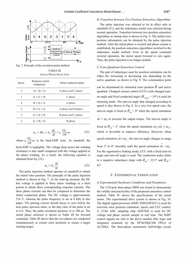
Fig. 7. Principle of the excitation pulse method.
TABLE III INITIAL PHASE SELECTION
Sector Response current
comparison Initial conduction phase
5 Ia ≥ Ib ≥ Ic A-phase and C-phase
1 Ia ≥ Ic ≥ Ib C-phase
4 Ib ≥ Ia ≥ Ic A-phase
6 Ib ≥ Ic ≥ Ia A-phase and B-phase
3 Ic ≥ Ia ≥ Ib B-phase and C-phase
2 Ic ≥ Ib ≥ Ia B-phase
k kk k k k
di Lu Ri L idt
wq
¶= + +
¶ (21)
where kk
Li wq
¶¶
is the back-EMF term. At standstill, the
back-EMF is negligible. The voltage drop across the winding resistance is also small compared with the voltage applied to the phase winding. As a result, the following equation is obtained from Eq. (21).
k kiu Lt
D=
D (22)
The pulse injection method operates at standstill to obtain the initial rotor position. The principle of the pulse injection method is shown in Fig. 7. At the start-up moment, the DC bus voltage is applied to three stator windings in a short period to obtain three corresponding response currents. The three phase currents can then be compared to determine the initial conduction phase. The DC voltage is approximately 514 V, whereas the pulse frequency is set at 4 kHz in this paper. The pulsing current should decay to zero before the next pulse injection starts, so the duty ratio of the pulse is set to 0.4. Thus, the pulse excitation duration Δt is 100 μs. The initial phase selection is shown in Table III for forward command. Table III shows that the two phases are conducted simultaneously at certain rotor positions to ensure a larger starting torque.
B. Transition between Two Position Sensorless Algorithms The pulse injection was selected to be in effect only at
standstill [21], and the inductance model was selected during normal operation. Transition between two position sensorless algorithms at startup time is shown in Fig. 8. The initial rotor position information can be obtained by the pulse injection method. After the initial phase is excited and phase current is established, the position sensorless algorithms switched to the inductance model method. Even in the speed command reversal operation, the motor speed lowered to zero again. Thus, the pulse injection is no longer needed.
C. Four-Quadrant Sensorless Control The part of inductance used for position estimation can be
either the increasing or decreasing one depending on the active quadrant, as shown in Fig. 9. The commutation point
can be determined by estimated rotor position Ù
q and active quadrant. Chopped current control (CCC) with changed turn-
on angle and fixed conducted angle ( condq = 19°) is used for
motoring mode. The turn-on angle that changed according to speed is also shown in Fig. 8. In a very low-speed case, the
turn-on angle is fixed at onq = 0° when the speed estimation Ù
w < 1w to increase the output torque. The turn-on angle is
fixed at onq = 2° when the speed estimation 1w ≤Ù
w ≤ 2w ,
which is favorable to improve efficiency. However, when
speed estimation Ù
w ≥ 2w , the turn-on angle changes in range
from 2° to 0° smoothly until the speed estimation Ù
w = 3w .
For the regenerative braking mode, CCC with a fixed turn-on angle and turn-off angle is used. The conduction pulse slides to a negative inductance slope with onq = 22.5° and offq =
42°.
V. EXPERIMENTAL VERIFICATION
A. Experimental Hardware Conditions and Parameters The 12/8-pole three-phase SRM was tested to demonstrate
the validity and practicality of the proposed sensorless control method. Table IV shows the specifications of the tested motor. The experimental drive system is shown in Fig. 10. The digital signal processor (DSP) TMS320F2812 is used for real-time rotor position estimation, speed, and CCC control. A 12-bit ADC sampling chip ADS7864 is used for DC voltage and phase current sample in real time. The IGBT control signals are sent to the driver module after logic and integrated treatment by the EP1K30QC208 FPGA of ALTERA. The three-phase asymmetric half-bridge circuit

1248 Journal of Power Electronics, Vol. 14, No. 6, November 2014
00=onq 02=onq02=onq onqonq
min/1001 r=w min/5002 r=w min/13503 r=w1w-2w-3w- ww-
Fig. 8. Transition between two position sensorless algorithms and selection for motoring mode.
,onqⅠ
,offqⅠ
0o2 / rNp-,onqⅡ
,offq Ⅱ/ rNp/ rNp-
,onqⅢ
,offqⅢ
0o2 / rNp-
,offqⅣ
w
cmT
Fig. 9. Four-quadrant operation. Fig. 10 Hardware of the sensorless control system.
ABCiyq
ww*
dcu
1 6IG -
/ iy
0L 1L 2L
PWMST
refIWorkMode
Active
L
+
-
Udc
AI
BI
CIABCi
ABCi
ABCi
Ai Bi Ci
Fig. 11. Block diagram of a sensorless control system. implemented with the FF150R12KE3G as the main switching device IGBT is used as the power converter. The load machine is a DC motor. The DC motor is controlled by a Siemens 6RA70 in the experiment, which runs synchronously with the SRM drive.
B. Software Implementation
Figure 11 shows that the software within the dashed frame is implemented by DSP and a complex programmable logic device (EP1K30) hybrid controller, which consists of the following parts:
1) A PI controller is designed to provide the chopping
current reference refI and CCC pulse generator module. Thus,
the speed closed-loop can be implemented.
The Main Controller
The Main Control Board 18.5kwSRM DC Motor
Power Converter 2812 DSP FPGAADS7864

Variable Coefficient Inductance Model-Based … 1249
TABLE IV PROTOTYPE PARAMETERS
SRM Prototype Rated Power
Applied DC bus voltage Rated Speed
Maximum Speed
12/8 structure SRM 18.5 kW
514 V DC 1000 r/min 1350 r/min
Fig. 12. Time schedule for each module of the sensorless program.
2) Through sampling of the AD module, the bus voltage
dcu signal and three-phase current signal are converted to a
digital signal that can be recognized by DSP. 3) The phase voltage is determined by means of a logic
using the levels of the gate switch impulses (PWMST) and
the bus voltage dcu by Eq. 15. Through the flux calculated
module, the ohmic voltage drop above the phase resistance is deducted from the phase voltage. This voltage difference was integrated up to the flux linkage by Eq. 14.
4) The flux linkage y and phase current ABCi are
transmitted to the phase inductance estimated module. The
phase inductance Ù
L was calculated by using Eq. 17.
5) The three coefficients 0L , 1L , and 2L estimated by Eq.
13. The phase inductance value Ù
L is transmitted to the
position-estimated module. Finally, the rotor position Ù
q was calculated by Eq. 18.
6) Sensorless commutation control of the switched reluctance motor was accomplished based on the estimated
result Ù
q by commutation module. The rotor speed wÙ
can be obtained according to the interval of commutation.
The time budget of the major software functions for the SRM controller is shown in Fig. 12.
C. Sensorless Starting The short period pulse is injected to three phases of the
12/8 SRM simultaneously. Fig. 13(a) shows the current pulse depicted by the experiment, C A BI I I> ³ , whereas the B-phase and C-phase are the initial phases. Fig. 13(b) shows the estimated position at the starting moment. The estimated
aI
bI
cI
I(10
A/d
iv)
aI
bI
cI
estq
Fig. 13. Position estimation at standstill.
TABLE V ESTIMATION ERROR AT DIFFERENT SPEEDS
Speed (r/min) Error (mech. eg.)
100 350 600 850
1100 1350
1.5 1.3 1.3 1.2 1.0 0.9
position is continuous and smooth between 0° and 15° mechanical degrees for each cycle. This finding verifies that the initial position can be obtained precisely.
D. Position Estimation in Light Load Conditions at Different Speeds Figs. 14 to 17 show the position estimation results at 20%
of the rated load conditions at 100, 500, 1000, and 1350 rpm, respectively. The traces show the phase current pulses, synthetic inductance, actual position, and estimated rotor position from top to bottom. Fig. 14(a) shows the third trace, whereas the marked 1, 2, 3, and 4 regions of estimated position constitute one complete electrical cycle and exactly corresponds to one mechanical cycle of the actual position (0°–45°). Figs. 14 to 17 show that the proposed estimation method has good accuracy from low speed (100 r/min) to the maximum speed (1350 r/min). As mentioned in Part C of Section IV, the turn-on angle is changed according to speed and decreased to nearly 0° at 1350 r/min when speed

1250 Journal of Power Electronics, Vol. 14, No. 6, November 2014
t
I
Lq
10o
t
I
Lq
10o
Fig. 14. Experimental result at 100 r/min.
tI
Lq
10o
t
I
Lq
10o
Fig. 15. Experimental results at 500 r/min.
Fig. 16. Experimental result at 1000 r/min.
t
I
Lq
10o
t
I
Lq
10o
Fig. 17. Experimental results at 1350 r/min.

Variable Coefficient Inductance Model-Based … 1251
aI
est
q
aI
est
q
Fig. 18. Experimental results in rated operation conditions.
estimation Ù
w ≥ 500 r/min. Table V shows the estimation error under a light load at different speeds. As the speed increases, the estimation error decreases.
E. Position Estimation in Rated Conditions Fig. 18 shows the position estimation results in rated load
conditions at 1350 rpm. Figs. 18(a) and 18(b) show the traces from top to bottom, which depict the phase current pulses, synthetic inductance, actual position, and estimated position. The current shape in Fig. 18 is different from that in Fig. 17 because when the phase current pulses increases to a rated current, the back EMF is near the DC–bus voltage at 1350 rpm. Therefore, the current control is lost because of high back EMF in rated conditions and the current chopping phenomenon disappeared. Fig. 18(a) shows that the estimated position is still parallel with the actual position, and the commutation control is normal in rated load conditions.
Fig. 19 shows the prototype efficiency at different speeds in rated load conditions. The efficiency is increased with the increase in speed. When the speed is more than 700 r/min, the efficiency can reach above 90%.
F. Dynamic Performance in Speed Reversal Test The speed reversal test was also performed to verify the
practicality of the proposed system. During this test, the SRM drive in 50% of the rated load conditions operating as a motor starts in a clockwise direction and, after a certain number of revolutions, the speed command was changed from 1200 r/min to ˗1200 r/min. It would then stop and start in the opposite direction.
Fig. 19. Prototype efficiency at different speeds.
t
t
I
q10
on
I
q10
on
Fig. 20. Experimental results in the speed reversal test.
Fig. 20(a) shows the process in the speed reversal test. The
reversal process is as follows: the motor first starts braking and decreases its speed. After a short transition at zero speed, the motor phase begins to pick up speed in the opposite direction. The figure shows that the speed reversal process takes approximately 1.2 s only.
Fig. 20(b) shows the detailed process in the speed reversal test. The estimated position based on the inductance model is almost unchanged at nearly zero speed. Thus, the algorithm is suitable at very low speeds.
VI. CONCLUSIONS A new sensorless control method for SRM drives is
presented in this paper. This approach can be used to estimate

1252 Journal of Power Electronics, Vol. 14, No. 6, November 2014
the position based on the variable coefficients inductance model. The new algorithm for position estimation combines pulse injection at a standstill, which can drive the SRM from standstill to high speed operation smoothly. Phase selection and estimator commutation for different modes is also designed and implemented. The sensorless method works at a series of speed transients both in acceleration and deceleration. Results show that the four-quadrant sensorless control of the SRM drive is a feasible technique that can be considered ready for application. This sensorless method requires no additional hardware, which makes it relatively easy to implement. These features make the proposed method practical, reliable, and cost effective as well as acceptable in many variable-speed applications. Experimental results fully verify the proposed sensorless scheme and demonstrate its advantages.
REFERENCES [1] R. Krishnan, Switched Reluctance Motor Drives: Modeling,
Simulation, Analysis, Design and Applications, CRC Press, 2001.
[2] M. Ehsani and B. Fahimi, “Elimination of position sensors in switched reluctance motor drives: State of the art and future trends,” IEEE Trans. Ind. Electron., Vol. 49, No. 1, pp. 40-47, Jan. 2002.
[3] H. X. Wu, T. Ni,Q. B. Guo, and Y. G. Ye, “Summary of detecting rotor position technique for switched reluctance motors,” Micro Motors, Vol. 44, pp. 76-83, Mar. 2011.
[4] L. G. Gallegos, P. C. Kjaer, and T. J. EMiller, “High-grade position estimation for SRM drives using flux linkage/current correction model,” IEEE Trans. Ind. Appl., Vol. 34, No. 4, pp. 859-869, Apr. 1998.
[5] T. Koblara, C. Sorandaru, S. Musuroi, and M. Svoboda, “A low voltage sensorless switched reluctance motor drive using flux linkage method,” in International Conference on Optimization of Electrical and Electronic Equipment Conf., pp. 665-672, 2010.
[6] J. P. Lyons, S. R. MacMinn, and M. A. Preston, “Flux-current methods for SRM rotor position estimation,” in Proc. IEEE Annual Meeting on Industry Applications Society Conf., pp. 482-487, 1991.
[7] Y. H. Qiu, Q. H. Zhan, Z. Y. Ma, and W. Guo, “The indirect position sensing of SRM on the basis of simplified flux method,” in Proc. the CSEE, Vol. 21, pp. 59-62, Oct. 2001.
[8] G. J. Tan, Z. L. Ma, S. Y. Kuai, and X. L. Zhang, “Four-quadrant position sensorless control inswitched reluctance motor drives based on sliding mode observer,” in International Conference on Electrical Machines and System Conf., pp. 1-5, 2009.
[9] M. S. Islam, I. Husain, R. J. Veillette, and C. Batur, “Design and performance analysis of sliding-mode observers for sensorless operation of switched reluctance motors,” IEEE Trans. Contr. Syst. Technol., Vol. 11, No. 3, pp. 383-389, Mar. 2003.
[10] C. Elmas and H. Z. L. Parra, “Application of a full-order extended Luenberger observer for a position sensorless operation of a switched reluctance motor drive,” in IEE Proceedings of Control Theory and Applications Conf., pp. 401-408,1996.
[11] A. K. Jain and N. Mohan, “Dynamic modeling, experimental characterization, and verification for srm
operation with simultaneous two-phase excitation,” IEEE Trans. Ind. Electron., Vol. 53, No. 4, pp. 1238-1249, Jun. 2006.
[12] C. L. Xia, M. C. Wang, T. N. Shi, and P. J. Guo, “Position sensorless control for switched reluctance motors using neural network,” in Proc. the CSEE, Vol. 25, pp. 123-128, 2005.
[13] P. C. Desai, M. Krishnamurthy, N. Schofield, and A. Emadi, “Novel switched reluctance machine configuration with higher number of rotor poles than stator poles:concept to implementation,” IEEE Trans. Ind. Electron., Vol. 57, No. 2, pp. 649-659, Feb. 2010.
[14] Y. Cai, Z. L. Xu, and C. Gao, “Simulation of SRD based on neural net nonlinear model,” Transactions of China Electrotechnical Society, Vol. 21, pp. 25-30, Aug. 2006.
[15] L. W. Ji, J. P. Jiang, and F. He, “Modeling of switched reluctance motors based on radial basis function neural network,” Transactions of China Electrotechnical Society, Vol. 16, pp. 7-11, Apr. 2001.
[16] M. Shinji, M. Yojiro, and M. Ichiro, “A rotor position estimation for 3-phase switched reluctance motor based on complex plane expression,” in Electrical Machines and Systems (ICEMS) Conf., pp. 1701-1705, 2010.
[17] J. Cai and Z. Q. Deng, “Sensorless control of switched reluctance motor based on phase inductance vectors,” IEEE Trans. Power Electron., Vol. 27, No. 7, pp. 3410-3423, Jul. 2012.
[18] S. Misawa and I. Miki, “A rotor position estimation using fourier series of phase inductance for switched reluctance motor,” in Power Electronics Electrical Drives Automation and Motion (SPEEDAM) Conf., pp. 1259-1263, 2010.
[19] J. C. Zhou, X. L. Wang, Z. Q. Deng , J. Cai, and D. P. Zou, “The position sensorless technology of switched reluctance motor based on the regional comparison of three-phase inductance,” Transations of China Electrotechnical Society, Vol. 27, pp. 34-40, Jul. 2012.
[20] J. Cai and Z. Q. Deng, “Sensorless control of switched reluctance motors based on phase inductance model in linear regions,” in Proc. the CSEE, Vol. 32, pp. 114-123, 2012.
[21] M. Krishnamurthy, C. S. Edrington, and B. Fahimi, “Prediction of rotor position at standstill and rotating shaft conditions in switched reluctance machines,” IEEE Trans. Power Electron., Vol. 21, No. 1, pp. 225-233, Jan. 2006.
Song-Yan Kuai was born in China in 1978. He received his B.S. and Ph.D. from China University of Mining and Technology, Xuzhou, China in 2000 and 2006, respectively. He has been an assistant professor at the School of Information and Electrical Engineering, China University of Mining and Technology since 2010. His
current research interests include switched reluctance motor, motor drive system for mine machinery, and sensorless techniques.
Xue-Feng Li was born in Henan, China, in 1990. He received his B.S. in Electrical Engineering from ShenYang University of Chemical Technology in 2012. He is currently working toward his M.S. at China University of Mining and Technology. His current research area is advanced control method of SRMs.

Variable Coefficient Inductance Model-Based … 1253
Xing-Hong Li was born in Heilongjiang, China in 1990. She received her B.S. in Electrical Engineering and Automation from Harbin Engineering University in 2013. She is currently working toward her M.S. at China University of Mining and Technology. Her current research area is advanced control method of SRM.
Jinyang Ma received his B.S. in Electronic Engineering and Management from Qingdao Technological University, Qingdao, China in 2013. He is currently studying Electric Engineering in China University of Mining and Technology. His main research areas include digital control of power electronics and sensorless controller for
SRMs.