Embed Size (px)
Citation preview

PRICE: $25.00
VANGUARD™ (RVN SERIES)
RECTIFIERS AND SHELVES
OPERATING MANUAL
www.unipowertelecom.com
Manual No. RVN-200-2 © 2000 UNIPOWER Corp.All Rights Reserved
UNIPOWER Telecom, Division of UNIPOWER Corporation
8/29/01 RVN-Vanguard-Man
NORTH AMERICA • 3900 Coral Ridge Drive, Coral Springs, Florida 33065, USA • Tel: +1 954-346-2442 • Fax: +1 954-340-7901 • [email protected] • Parkland Business Centre, Chartwell Road, Lancing BN15 8UE, ENGLAND • Tel: +44(0)1903 768200 • Fax: +44(0)1903 764540 • [email protected]

CONTENTS
SECTION TOPIC PAGE
1.0 Introduction 1
2.0 Important Features 3
3.0 Product Line 3
4.0 Safety Warnings 4
5.0 Warranty 4
6.0 Unpacking and Inspection 5
7.0 Description of Operation 5
8.0 Front Panel Description 6
9.0 Rectifier Module Specifications 6
10.0 Description of Features and Options 9
11.0 Mechanical Specifications 11
12.0 Safety and Industry Standards 11
13.0 Operating Information 12
14.0 Parallel Operation 15
15.0 Control & Supervisory Signal Connections 18
16.0 Description of COntrol & Supervisory Signals 18
17.0 Installation 20
18.0 Maintenance 21
19.0 Rectifier & Shelf Setup and Testing 21
20.0 Troubleshooting Guide 25
ILLUSTRATIONS
FIGURE TITLE PAGE
1 Vanguard Rectifier Modules and Shelves 2
2 Vanguard Rectifier Module Block Diagram 2
3 Front Panel of Vanguard Rectifier Module 7
4 Vanguard Series Mechanical Dimensions 7
5 Rear Shelf Input and Output Connections 13
6 Rated Output Current vs. Ambient Temperature 14
7 Typical Rectifier Current Limit Characteristics 14
8 Remote Sensing Connection 16
9 Parallel Connection of Vanguard Shelves 16
10 Checking AC Ground & DC Good Outputs 23
11 Checking Remote Adjust Input 23

1
VANGUARD™ SERIESOPERATING MANUAL
1.0 INTRODUCTION
This operating manual should be read through carefully before installing and operat-ing the Vanguard rectifier.
The Vanguard™ (RVN Series) rectifier modules and shelves operate as a completehot-swap power system for charging a 48V or 24V lead-acid battery or directlypowering a load. See Figure 1. Each rectifier module produces up to 20 amperes at54.4VDC (48V version) or 40 amperes at 27.2VDC (24V version). The 48V versionis factory set to 54.4VDC output and the 24V version is factory set to 27.2VDC.Three rectifiers in a 19-inch shelf produce up to 60A at 54.4VDC or 120A at27.2VDC; four rectifiers in a 23-inch shelf produce up to 80A at 54.4VDC or 160Aat 27.2VDC. The rectifiers have single-wire active load sharing for automatic para-lleling, and output ORing diodes which permit hot-swap addition or replacement ofmodules while the power system is operating. A shelf with rectifier modules canalso be operated as an N+1 redundant power system with hot-swap, no-downtimereplacement of a faulty module.
These power systems operate with a wide 103 to 265VAC input range at 47 to 63Hzand a separate AC input connection to each rectifier module. The modules haveinput power factor correction and Class B EMI input filters. The output voltage istightly regulated and precisely adjustable over a wide range of 40 to 58VDC or 20 to29VDC by means of a front panel, 12-turn potentiometer. Each module also has aremote analog input which can be used to adjust the output voltage over the samerange. Using an external power controller in conjunction with this input permitsautomatic battery voltage control of equalize and float voltages together with tem-perature-compensated charging. The rectifiers can operate into a zero-voltage(dead) battery or short circuit without harm to the system. The output overloadcharacteristic is a constant power output above 48V or 24V (depending on model)and a constant current output below these voltages. The output is floating withrespect to frame or AC grounds.
A 25-pin interface subminiature D connector on the backplane of the shelf furnishescontrol and monitoring inputs and outputs. An enable input turns the entire shelfoutput off or on. Remote sensing connections provide precise regulation at thebattery or point of load. Other control signals are AC good, DC good and thermalalarm logic outputs; analog voltage current monitor outputs; and analog voltageremote adjust inputs - - all for each individual rectifier module.
VANGUARD™ (RVN SERIES) RECTIFIERS AND SHELVESOPERATING MANUAL

2
VANGUARD™ SERIESOPERATING MANUAL
Figure 1. Vanguard Rectifier Modules and Shelves.
Figure 2. Vanguard Rectifier Block Diagram.

3
VANGUARD™ SERIESOPERATING MANUAL
Front-panel green LEDs indicate AC power good, DC power good and output cur-rent for each rectifier module. The output current is displayed by a five-segmentLED showing 20% of full load current per segment. The rectifier modules andshelves are safety agency certified and CE marked.
2.0 IMPORTANT FEATURES
The following is a summary of the important features of the Vanguard rectifier mod-ules and shelves:
u Charges Batteries or Powers Loads Directlyu Constant Output Voltageu Front Panel Output Adjustmentu Remote Analog Output Adjustmentu Wide Range Output Voltage Adjustmentu Output Overload Protectedu 48VDC and 24VDC Versionsu Low Profile: 2 Mounting Positions (3.5 inches or 89mm) Heightu 19 or 23-Inch Shelvesu Shelf Capacity Up to 4 Rectifier Modulesu High Power Density: 6.1 Watts/Cubic Inchu Light Weight: 7.15 lbs. per Rectifier Moduleu 87% Efficiencyu 0.99 Power Factoru Class B EMI Input Filteru Wide Range Input: 103-265 VAC at 47-63Hzu Battery Temp. Compensated Charge Regulation*u Remote Sensingu Active, Single-Wire Load Sharingu Integral ORing Diodesu Hot-Swappable Rectifier Modulesu Redundant or Non-Redundant Operationu LED Operating Indicatorsu Control and Monitoring Interface Signals
* With external power controller
3.0 PRODUCT LINE
3.1 Rectifier Modules
RVN48/20 48VDC 54.4V 20A
RVN24/40 24VDC 27.2V 40A
MODEL NOMINALOUTPUT
MAX. OUTPUTCURRENT
FACTORY SETOUTPUT

4
VANGUARD™ SERIESOPERATING MANUAL
3.2 Shelves
3.3 AC Input Options
NOTE: Add Option Code Letter as suffix to the shelf model number.
4.0 SAFETY WARNINGS
4.1 These rectifier modules and shelves have hazardous external and internalvoltages. They should be handled, tested and installed only by qualifiedtechnical persons who are trained in the use of power systems and are wellaware of the hazards involved.
4.2 The input terminals are at hazardous voltage potentials. Do not touch thisarea when power is applied.
4.3 When operating this rectifier system, the frame ground terminal must beconnected to safety ground by means of a three-wire AC power line to mini-mize electrical shock hazard and to ensure low EMI (electromagnetic interfer-ence).
4.4 The internal voltages are at hazardous potentials. The rectifier module coversshould not be removed. There are no user-serviceable components in theseunits. Removing the covers of the rectifier modules will void the warranty.
5.0 WARRANTY
All products of UNIPOWER Telecom, a division of UNIPOWER Corporation, are warranted fortwo (2) years from date of shipment against defects in material and workmanship. This warrantydoes not extend to products which have been opened, altered or repaired by persons other thanpersons authorized by the manufacturer or to products which become defective due to acts ofGod, negligence or the failure of customer to fully follow instructions with respect to installation,
RVN2U-19 48 19” (483MM) 3.5” (89MM) 3 60A
RVN2U-23 48 23” (584MM) 3.5” (89MM) 4 80A
RVN2U-19 24 19” (483MM) 3.5” (89MM) 3 120A
RVN2U-23 24 23” (584MM) 3.5” (89MM) 4 160A
NUMBER OFMODULES
MAX. OUTPUTCURRENT
MODEL NOM.VOLTS
WIDTH HEIGHT
C IEC AC Input Connectors
D AC Input Conduit Connections
CODE OPTION
5
VANGUARD™ SERIESOPERATING MANUAL
application or maintenance. This warranty is extended directly by the manufacturer to the buyerand is the sole warranty applicable. EXCEPT FOR THE FOREGOING EXPRESS WARRANTY,THE MANUFACTURER MAKES NO WARRANTY, EXPRESS OR IMPLIED, INCLUDING, BUTNOT LIMITED TO, THE WARRANTY OF MERCHANTABILITY OR FITNESS FOR A PARTICU-LAR PURPOSE. As the sole and exclusive remedy under this warranty, the manufacturer, at itsoption, may repair or replace the non-conforming product or issue credit, provided themanufacturer’s inspection establishes the existence of a defect. To exercise this remedy, thebuyer must contact the manufacturer’s Customer Service Department to obtain a Return MaterialAuthorization number and shipping instructions. Products returned without prior authorizationwill be returned to buyer. All products returned for repair must be shipped freight prepaid toUNIPOWER. If the buyer fails to fully comply with the foregoing, the buyer agrees that no otherremedy (including, but not limited to, incidental or consequential damages for lost profits, lostsales, injury to person or property or any other incidental or consequential losses) shall beavailable to the buyer.
6.0 UNPACKING AND INSPECTION
6.1 This Vanguard Series Rectifier System was carefully tested, inspected andpackaged for shipment from our factory. Upon receipt of the unit it should becarefully unpacked and inspected for any damage in shipment.
6.2 If there is evidence of damage, do not attempt to test the unit. The freightcarrier should be notified immediately and a claim for the cost of the rectifiersystem should be filed with the carrier for direct reimbursement. Be sure toinclude the model and serial number of the damaged unit in all correspon-dence with the freight carrier. Also save the shipping carton and packingmaterial as evidence of damage for the freight carrier’s inspection.
6.3 UNIPOWER Telecom will cooperate fully in case of any shipping damageinvestigation.
6.4 Always save the packing materials for later use in shipping the unit. Nevership the rectifier system without proper packing.
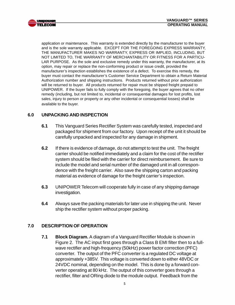
7.0 DESCRIPTION OF OPERATION
7.1 Block Diagram. A diagram of a Vanguard Rectifier Module is shown inFigure 2. The AC input first goes through a Class B EMI filter then to a full-wave rectifier and high-frequency (50kHz) power factor correction (PFC)converter. The output of the PFC converter is a regulated DC voltage atapproximately +385V. This voltage is converted down to either 48VDC or24VDC nominal, depending on the model. This is done by a forward con-verter operating at 80 kHz. The output of this converter goes through arectifier, filter and ORing diode to the module output. Feedback from the

6
VANGUARD™ SERIESOPERATING MANUAL
remote sense terminals back to the forward converter pulse-width modulatorregulates the output voltage and keeps it constant.
7.2 Power Factor Correction. This high-frequency converter circuit achieves apower factor of 0.99 by forcing the AC input current into a sinusoidal wave-form, in phase with the input voltage. The input current is a smooth sinewave of much lower amplitude than the normal series of high-amplitude, inputcurrent pulses that are present in a unit without power factor correction. Theresult is lower RMS input current for a given output power level.
7.3 Cooling Fans. Another output from the forward converter is rectified, filteredand used to power the two DC ball bearing cooling fans on the rectifier mod-ule.
7.4 Interface Signals. The rectifier incorporates a number of interface controland supervisory signals which operate off internal circuits and are brought tothe outside. These include remote enable, which enables or inhibits theentire shelf, and a current share connection which permits operating the shelfin parallel with other shelves for increased power. Other signals brought outof the shelf for each rectifier module include thermal alarm, current monitor,AC good, DC good and a remote adjust which permits adjustment of eachrectifier output voltage by means of an external analog control voltage.
8.0 FRONT PANEL DESCRIPTION
The front panel of a Vanguard rectifier module is shown in Figure 3. From left toright are: output voltage adjustment potentiometer (12-turn), AC Good LED (green),DC Good LED (green) and the 5-LED (green) output current monitor which indi-cates 20% of full load current per LED. There are two 60 mm cooling fans and avertical handle between them.
9.0 RECTIFIER MODULE SPECIFICATIONS
Specifications for a Single Rectifier Module. Typical at 115/230VAC Line, Full Load and 25°CUnless Otherwise Noted.

7
VANGUARD™ SERIESOPERATING MANUAL
Figure 4 . Vanguard Series Mechanical Dimensions
Figure 3 . Front Panel of Vanguard Rectifier Module
3.50 (89)
19.00(483)
u
u
u
u
3.50 (89)
23.00(584)
u
u
u
u

8
VANGUARD™ SERIESOPERATING MANUAL
INPUTVoltage Range ............................................... 103-265VACPower Factor ................................................. 0.99Total Harmonic Distortion, Max. .................... 5%Frequency ..................................................... 47-63HzInrush Current Limiting ................................. 50A PeakInput Current, Full Load ................................ 10.5A@120VAC . ............................... 5.5A@230VACEMI Filter, Conducted ................................... FCC20780 pt. 15J Curve B
................................... EN55022 Curve BFast Transients, Line-Line ............................. EN61000-4-4, Level 3Surges, Line-Line .......................................... EN61000-4-5, Level 2
Line-Ground ..................................... EN61000-4-5, Level 3
OUTPUTCurrent & Voltage1 ......................................... [email protected]
......................................... [email protected] Adjustment Range, 48V Nominal ..... 40.0-58.0VDC
24V Nominal ..... 20.0-29.0VDCLine & Load Regulation, Max. ....................... 0.5%Holdup Time .................................................. 20msec.Overvoltage Protection, 48V Out ................... 59V 24V Out .................. 29VFiltering: Wideband Noise, 20MHz BW 48V Out, P-P ........................................... 500mV 24V Out, P-P ........................................... 250mVVoice Band Noise .......................................... <32dBrnCCurrent Limit .................................................. 105% Rated CurrentEfficiency ....................................................... 87%
SAFETY STANDARDS ................................. UL1950, CSA22.2-950, EN60-950
STATUS INDICATORSAC Good ....................................................... Green LED and Logic LO OutputDC Good ....................................................... Green LED and Logic LO OutputOutput Current .............................................. 5-Seg. Green LED Bar Graph
............................................... Proportional Analog Output VoltageThermal Alarm ............................................... Logic HI Output
ENVIRONMENTALOperating Temp. Range ................................ 0°C to +70°COutput Current Derating ................................ 2.5%/°C, 50°C to 70°CStorage Temp. Range ................................... -40°C to + 85°CHumidity ........................................................ 0% to 95%, Non-CondensingMTBF ............................................................. >250,000 HoursCooling .......................................................... Internal DC Ball Bearing Fans
9
VANGUARD™ SERIESOPERATING MANUAL
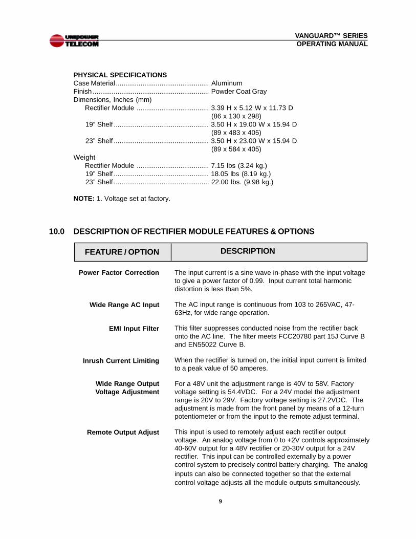
PHYSICAL SPECIFICATIONSCase Material ................................................. AluminumFinish ............................................................. Powder Coat GrayDimensions, Inches (mm) Rectifier Module ...................................... 3.39 H x 5.12 W x 11.73 D
(86 x 130 x 298) 19” Shelf .................................................. 3.50 H x 19.00 W x 15.94 D
(89 x 483 x 405) 23” Shelf .................................................. 3.50 H x 23.00 W x 15.94 D
(89 x 584 x 405)Weight Rectifier Module ...................................... 7.15 lbs (3.24 kg.) 19” Shelf .................................................. 18.05 lbs (8.19 kg.) 23” Shelf .................................................. 22.00 lbs. (9.98 kg.)
NOTE: 1. Voltage set at factory.
10.0 DESCRIPTION OF RECTIFIER MODULE FEATURES & OPTIONS
DESCRIPTION
The input current is a sine wave in-phase with the input voltageto give a power factor of 0.99. Input current total harmonicdistortion is less than 5%.
The AC input range is continuous from 103 to 265VAC, 47-63Hz, for wide range operation.
This filter suppresses conducted noise from the rectifier backonto the AC line. The filter meets FCC20780 part 15J Curve Band EN55022 Curve B.
When the rectifier is turned on, the initial input current is limitedto a peak value of 50 amperes.
For a 48V unit the adjustment range is 40V to 58V. Factoryvoltage setting is 54.4VDC. For a 24V model the adjustmentrange is 20V to 29V. Factory voltage setting is 27.2VDC. Theadjustment is made from the front panel by means of a 12-turnpotentiometer or from the input to the remote adjust terminal.
This input is used to remotely adjust each rectifier outputvoltage. An analog voltage from 0 to +2V controls approximately40-60V output for a 48V rectifier or 20-30V output for a 24Vrectifier. This input can be controlled externally by a powercontrol system to precisely control battery charging. The analoginputs can also be connected together so that the externalcontrol voltage adjusts all the module outputs simultaneously.
Power Factor Correction
Wide Range AC Input
EMI Input Filter
Inrush Current Limiting
Wide Range OutputVoltage Adjustment
FEATURE / OPTION
Remote Output Adjust

10
VANGUARD™ SERIESOPERATING MANUAL
If either the PFC converter stage or the output power converteroverheats, the rectifier module will automatically shut down andgive an output alarm logic HI. The DC Good LED also turns off.After about 10 minutes the rectifier module will cool and auto-matically start up again.
The Vanguard rectifier modules are automatically connected tocurrent share with each other when they are inserted into theshelf. A single-wire connection provides this. The modulescurrent share with an accuracy of 10% of their full load outputcurrent for total loads of 50% to 100%. The shelf current sharepin can be used to current share with another shelf of thesame output voltage.
This diode in series with each module output protects the paral-lel-connected modules. If the output of one module fails to ashort or to a lower than normal output voltage, the other modulesare not affected. Also when hot-swapping modules, the diodeprevents a glitch in the output voltage while the output is stillrising on the inserted module.
The output is protected from overvoltage due to fault conditionsin the module. Overvoltage protection is set at approximately59V for the 48V version and 29V for the 24V version. Theresult is a latched shutdown of the rectifier module. It is resetby cycling the AC input off for 20 seconds, and then on.
The module output can be operated down to zero load whilemaintaining output regulation.
The hot plug connectors used in both the modules and shelvesare high-reliability connectors specifically designed for hot swapapplications. They have staged pin lengths for safety andoptimum operation. The ground (common) pin makes firstcontact and an interlock pin makes last contact, turning therectifier module on (provided the shelf is “enabled”).
Hot swap operation means that the rectifier modules can beremoved and replaced while the shelf is powering the load. If theshelf is operated in an N+1 redundant mode, hot-swap replace-ment will not affect the output voltage.
Output current limiting protects the output of each rectifiermodule from damage due to a dead battery or other short circuitcondition. This protection is continuous, without damage, andrecovery is automatic when the overload is removed. The currentlimit characteristic is essentially a constant power limit above 48Vor 24V (depending on model) and a constant current limit belowthese values. Current limiting begins at about 105% of ratedoutput current.
FEATURE / OPTION
Thermal Protection
Current Sharing
ORing Diodes
Overvoltage Protection
No Load Operation
Hot Plug Connectors
DESCRIPTION
Hot Swap Operation
Output Protection

11
VANGUARD™ SERIESOPERATING MANUAL
FEATURE / OPTION
The AC Good indicator is a green LED, showing that input AC ispresent and that the PFC converter and internal control supplyare operating. The DC Good indicator is a green LED showingthat the output voltage is present and within operating range.The output current monitor consists of five green LEDs in a row.Each LED, from left to right indicates 20% of full load current(4A for 48V model and 8A for 24V model).
There are two input options: IEC320 connectors of which eachshelf has one per rectifier module; or terminal blocks, one permodule, for conduit connections. These options are chosen atthe time of ordering.
For detailed description of Enable, Thermal Alarm, CurrentMonitor, Current Share, Remote Sense, Remote Adjust, ACGood and DC Good signals see Section 16, Description ofControl and Supervisory Signals.
LED Indicators
AC Input Options
Control and MonitoringSignals
11.0 MECHANICAL SPECIFICATIONSThe mechanical dimensions of the Vanguard Series rectifier modules and shelvesare shown in Fig. 4. Both 19-inch and 23-inch shelves are shown.
12.0 SAFETY AND INDUSTRY STANDARDS
12.1 The Vanguard rectifiers and shelves meet the following safety certifications:
STANDARD AGENCYUL1950 ULCSA22.2-950 CULEN60-950 DEMKO
12.2 The Vanguard rectifier and shelves are CE marked to indicate conformanceto the European Union’s Low Voltage Directive.
12.3 Input conducted EMI meets FCC20780 part 15J Curve B and EN55022Curve B.
12.4 Input fast transient specifications meet EN61000-4-4 Level3; input surges,line-to-line, meet EN61000-4-5 Level 2; and input surges, line-to-ground,meet EN61000-4-5 Level 3.
DESCRIPTION

12
VANGUARD™ SERIESOPERATING MANUAL
13.0 OPERATING INFORMATION
13.1 Input Voltage. The Vanguard Series rectifiers operate off worldwide ACinput voltages within the range of 103 to 265 VAC at 47 to 63 Hz. There aretwo AC input options chosen at the time of ordering: standard IEC320 con-nectors or conduit-cable type connections to terminal blocks. In both casesthere is a separate connection for each rectifier module at the rear of theshelf. For complete details see Section 17.2 and Figure 5 (a) and (b).
13.2 Output Connection. The 24V or 48V output is provided on two copper busbars. Each bus bar has a bracket with two 1/4-20 studs with nuts. Connec-tion should be made by means of two-hole barrel lugs. For complete detailssee Section 17.3 and Figure 5(c). Both positive and negative outputs arefloating with a minimum 100V isolation from the chassis.
13.3 Output Voltage. The output voltage of each rectifier module is factory set to54.4V for the 48V rectifier and 27.2V for the 24V rectifier. At these voltages, aminimum current of 20A or 40A is produced, respectively. If a different outputvoltage is required it should be accurately set for each module by means ofthe front panel, high resolution, 12-turn output adjustment potentiometer. Theoutput voltage can also be adjusted by means of the remote adjust inputconnected to an external voltage source. In both cases the adjustment rangeis 40-58V or 20-29V.
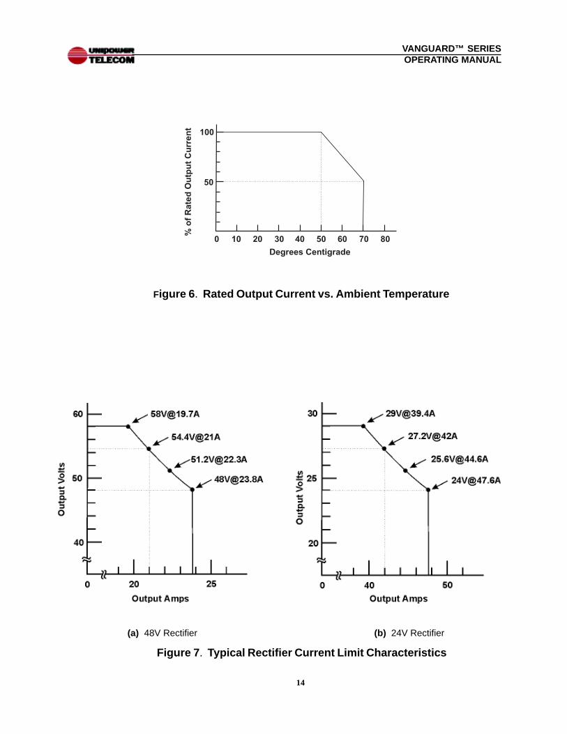
13.4 Output Power. Maximum output power is 20A at 54.4 VDC or 40A at 27.2VDC, both giving a total maximum output of 1,088 volt-amperes. The maxi-mum output power of a module may be drawn at up to 50oC ambient tem-perature. Above 50oC the output current must be derated by 2.5%/oC. SeeFig. 6. The maximum operating temperature is 70oC, at which the outputcurrent must be derated by 50%.
13.5 Output Overload Protection. Each rectifier module output is protectedfrom damage due to overload, a dead battery or another short circuit condi-tion. This protection is continuous and without damage; recovery is automaticwhen the load is removed. The current limit characteristic is shown in Fig. 7.and is essentially a constant power limit above 48V or 24V (depending onmodel) and a constant current limit below these voltages. At 54.4V limitingtakes place at approximately 21A; at 27.2V it takes place at approximately42A. These currents are 5% above the rated output currents at the givenvoltages.

13
VANGUARD™ SERIESOPERATING MANUAL
Figure 5 . Rear Shelf Input & Output Connections
14
VANGUARD™ SERIESOPERATING MANUAL
Figure 7 . Typical Rectifier Current Limit Characteristics
(b) 24V Rectifier(a) 48V Rectifier
Figure 6 . Rated Output Current vs. Ambient Temperature

15
VANGUARD™ SERIESOPERATING MANUAL
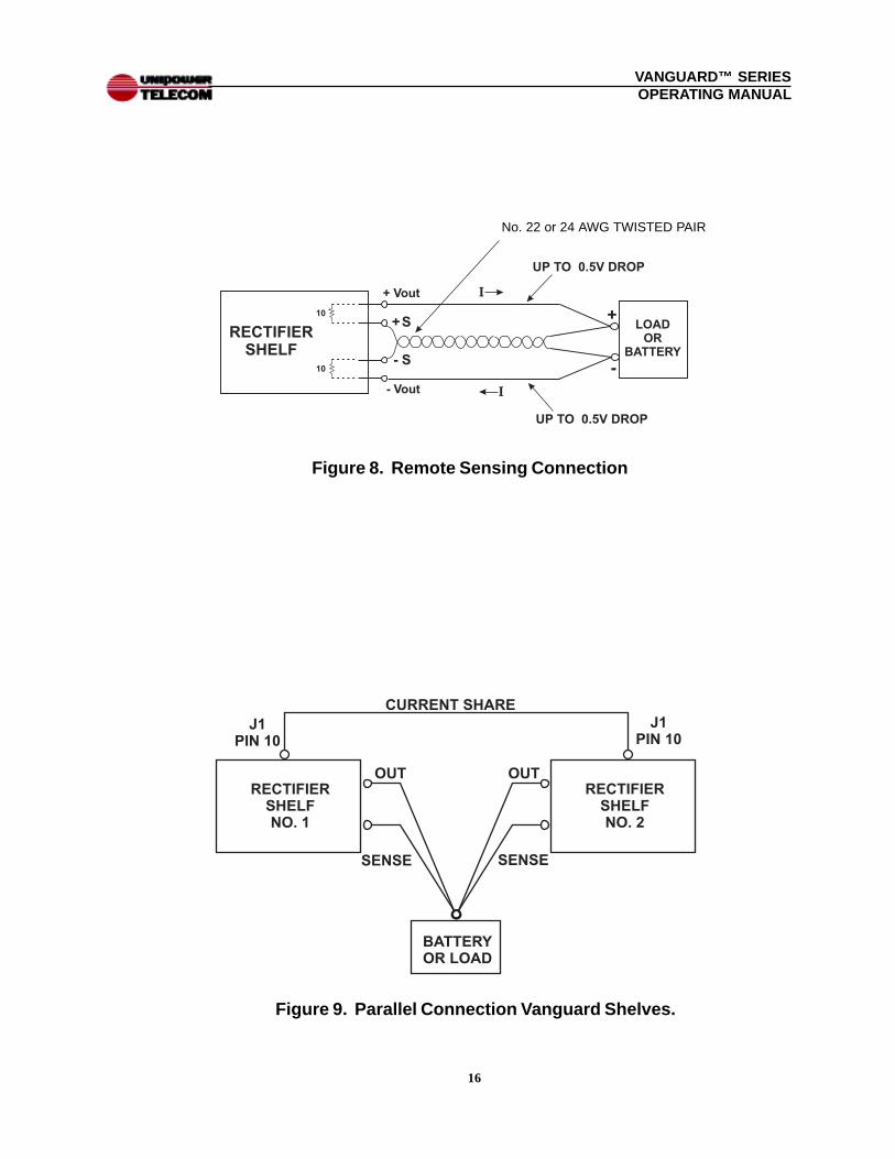
13.6 Remote Sensing. Remote sensing connections are made to pins 11(+Sense) and 23 (-Sense) of the rectifier shelf J1 connector. Remote sensingis used to regulate the output voltage at the point of load, i.e., a battery orother load, by compensating for the voltage drop in the wires to the load. The+Sense lead must be connected to the + side of the load and the -Sense tothe - side of the load. The sense leads should be a color-coded, twisted pairof AWG no. 22 or 24 copper wire. See Fig. 8.
Remote sensing can compensate for a total voltage drop of 1.0V, or 0.5V perload wire. The sense leads should not exceed 10 feet (3 meters) in length. Ifremote sensing is not required, the sense leads may be left open; there is aninternal 10-ohm resistor connected from each output to its remote sense lead.Be careful not to reverse the sense lead connections , as this will blowthe 10-ohm resistors.
13.7 Control Supervisory Signals. All control and supervisory signals areaccessible at J1, a 25-pin subminiature D connector on the back of therectifier shelf. See Section 16 for a complete description of these input andoutput signals.
13.8 Alarm Signals. Among the control and supervisory signals are three sets oflogic alarms: thermal alarm, AC good and DC good. All are opto-isolated,floating, open collector, TTL-compatible signals referenced to Signal Com-mon, J1 Pin 22. There are three logic alarms for each rectifier module. Thefirst alarm is Thermal Alarm . When a rectifier module internally overheats,this logic signal goes HI 100 msec. before the rectifier automatically shutsdown. After about 10 minutes the module will cool down and automaticallystart up again. The next alarm is AC Good . A logic HI indicates that there isno AC input or that the PFC converter stage has failed. The third alarm is DCGood. A logic HI indicates a DC output failure or a cooling fan failure.
14.0 PARALLEL OPERATION
The rectifier modules in the shelf are all connected in the parallel, current sharingmode by means of a single-wire current share connection among them. A shelf canbe operated in either an N+1 redundant mode or non-redundant mode.
14.1 Redundant Operation. From Table 14-1, the 19-inch shelf can be operatedin a 2+1 redundant mode and the 23-inch shelf can be operated in a 3+1redundant mode. This means, in the former case for example, that the fullload current must be carried by two rectifier modules. While operating
16
VANGUARD™ SERIESOPERATING MANUAL
Figure 9. Parallel Connection Vanguard Shelves.
Figure 8. Remote Sensing Connection
No. 22 or 24 AWG TWISTED PAIR

17
VANGUARD™ SERIESOPERATING MANUAL
normally, the current is shared approximately equally among the three mod-ules. If one module fails, however, the output current is then maintained bythe two operating modules. The failed unit can be replaced without affectingthe output current to the load. N+1 redundancy with quick replacement of afailed module results in virtually infinite MTBF.
Table 14-1 Redundant and Non-Redundant Operation
14.2 Non-Redundant Operation. Higher output current can be achieved byoperating the shelf in a non-redundant mode as seen in Table 14-1. How-ever, in this case if a rectifier module fails, the load will lose power since onlypart of the required current can be supplied by the remaining modules, andthey will go into current limit. The failed rectifier module, however, can bequickly replaced to restore the load current.
14.3 Multiple Parallel Shelf Operation. Multiple shelves can also be operated inparallel by interconnecting their current share terminals (J1 Pin 10). The totalpower can be expanded by several times. In this case N+1 redundant opera-tion is achieved by reserving one module of the total for redundancy. Forexample, if two full 19-inch shelves are employed with a total of six rectifiermodules, then for 5+1 redundancy the full load must be able to be carried bythe output of five modules. In such applications each set of remote sensewires must be separately connected to the battery or point of load. SeeFigure 9 for a simplified illustration of two rectifier shelves connected inparallel.
Redundant, 2+1 19-inch 3 48 40
Non-Redundant 19-inch 3 48 60
Redundant, 3+1 23-inch 4 48 60
Non-Redundant 23-inch 4 48 80
Redundant, 2+1 19-inch 3 24 80
Non-Redundant 19-inch 3 24 120
Redundant, 3+1 23-inch 4 24 120
Non-Redundant 23-inch 4 24 160
MODE SHELFWIDTH
NOM.VOLTS
NUMBER OFMODULES
AMPSMAX.

18
VANGUARD™ SERIESOPERATING MANUAL
15.0 CONTROL & SUPERVISORY SIGNAL CONNECTIONS
15.1 Connections for control and supervisory signals are made at the shelf rear toconnector J1, a standard 25-pin subminiature D connector (Positronics No.SD25F0S5OOX with FC752OD pins). The mating connector is PositronicsSD25M00OOZ with MC752OD pins.
15.2 The pin connections to J1 are shown in the table. Note that five of the pins(asterisked) are for connection to the fourth rectifier module in a 23-inch wideshelf.
16.0 DESCRIPTION OF CONTROL AND SUPERVISORY SIGNALS
Standard subminiatureD Connector
(PositronicsSD25F0S5OOX
with FC7520D pins)
This is an opto-isolated input. A TTL LO (sinking 5mA) or short toPin 22 enables (turns on) all rectifier modules in the shelf. Thisinput is referenced to Signal Common, Pin 22.
These are opto-isolated, floating, open collector outputs for thedesignated rectifier modules. A TTL LO (sinks 10mA) is normal.A TTL HI indicates thermal shutdown and occurs 100 msec.before the rectifier shuts down. These outputs are referenced toSignal Common, Pin 22.
These are analog output voltages which are proportional to theoutput currents of the designated rectifier modules over the fullload range. The scale is linear, 0 to +5V, with full scale represent-ing 25A for a 48V rectifier module and 50A for a 24V module.These outputs are referenced to -Sense, Pin 23.
Remote Enable
Thermal Alarm - 1
Thermal Alarm - 2
Thermal Alarm - 3
Thermal Alarm - 4
Current Monitor - 1
Current Monitor - 2
Current Monitor - 3
Current Monitor - 4
SIGNAL PIN
1
2
4
6
8
3
5
7
9
DESCRIPTION
J1 SIGNAL CONNECTORPIN FUNCTION
1 Remote Enable2 Thermal Alarm-13 Current Monitor-14 Thermal Alarm-25 Current Monitor-26 Thermal Alarm-37 Current Monitor-38 Thermal Alarm-4*9 Current Monitor-4*
10 Current Share11 + Sense12 Remote Adjust-213 Remote Adjust-4*
PIN FUNCTION14 AC Good-115 DC Good-116 AC Good-217 DC Good-218 AC Good-319 DC Good-320 AC Good-4*21 DC Good-4*22 Signal Common23 -Sense24 Remote Adjust-125 Remote Adjust-3
* These pins are used only on the 23-inch shelf. On the19-inch shelf they are No Connection.
J1

19
VANGUARD™ SERIESOPERATING MANUAL
This is an analog control signal made up of the current sharesignals of all rectifier modules connected together. This pin isused to connect to Pin 10 of another identical rectifier shelf toshare output currents. Output currents between shelves areshared within an accuracy of 10% of full load current over a 50%to 100% load range. This signal is referenced to -Sense, Pin 23.
These remote sense leads should be connected as a twisted pairto the respective + and - load points to provide regulation at thepoint of load. Removal of the sense leads transfers regulationcontrol to the output terminals of the rectifier shelf via internal 10-ohm sense resistors.
These are analog voltage inputs to the designated rectifier mod-ules by which the output voltage is adjusted. A zero to + 2V inputrepresents approximately 40 to 60V output for a 48V rectifiermodule or 20 to 30V for a 24V module. This input should bedriven from a source impedance less than 100 ohms and isreferenced to -Sense, Pin 23. If the input control voltage is above2.5V or the pin is left open, the output voltage reverts to the valuedetermined by the front panel potentiometer setting.
These are opto-isolated, floating, open collector outputs for thedesignated rectifier modules. A TTL LO (sinks 10mA) indicatesthe AC input is present and the PFC converter stage has output.A TTL HI indicates AC input or PFC converter failure. This signalis referenced to Signal Common, Pin 22.
These are opto-isolated, floating, open collector outputs for thedesignated rectifier modules. A TTL LO (sinks 10mA) indicatesthat the unit is operating properly with output voltage in its control-lable range. A TTL HI indicates the output is outside the 40-60Vrange for a 48V rectifier or outside the 20-30V range for a 24Vrectifier, the unit has failed or is in current limit, or there is acooling fan failure. This signal is referenced to Signal Common,Pin 22.
This is the reference common for the opto-isolated floating out-puts. This common floats with the external logic common.
Current Share
Remote Adjust - 1
Remote Adjust - 2
Remote Adjust - 3
Remote Adjust - 4
AC Good - 1
AC Good - 2
AC Good - 3
AC Good - 4
SIGNAL PIN
10
24
12
25
13
14
16
18
20
DESCRIPTION
DC Good - 1
DC Good - 2
DC Good - 3
DC Good - 4
15
17
19
21
Signal Common 22
11
23
+ Sense
- Sense
20
VANGUARD™ SERIESOPERATING MANUAL
17.0 INSTALLATION
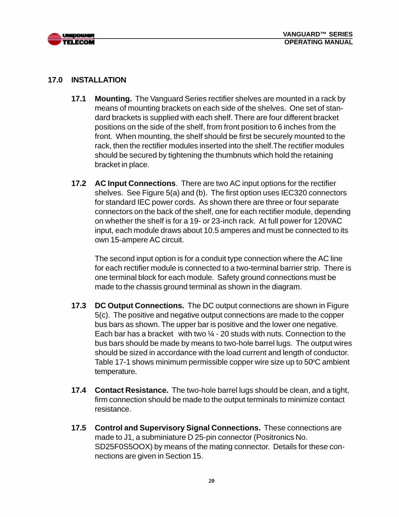
17.1 Mounting. The Vanguard Series rectifier shelves are mounted in a rack bymeans of mounting brackets on each side of the shelves. One set of stan-dard brackets is supplied with each shelf. There are four different bracketpositions on the side of the shelf, from front position to 6 inches from thefront. When mounting, the shelf should be first be securely mounted to therack, then the rectifier modules inserted into the shelf.The rectifier modulesshould be secured by tightening the thumbnuts which hold the retainingbracket in place.
17.2 AC Input Connections . There are two AC input options for the rectifiershelves. See Figure 5(a) and (b). The first option uses IEC320 connectorsfor standard IEC power cords. As shown there are three or four separateconnectors on the back of the shelf, one for each rectifier module, dependingon whether the shelf is for a 19- or 23-inch rack. At full power for 120VACinput, each module draws about 10.5 amperes and must be connected to itsown 15-ampere AC circuit.
The second input option is for a conduit type connection where the AC linefor each rectifier module is connected to a two-terminal barrier strip. There isone terminal block for each module. Safety ground connections must bemade to the chassis ground terminal as shown in the diagram.
17.3 DC Output Connections. The DC output connections are shown in Figure5(c). The positive and negative output connections are made to the copperbus bars as shown. The upper bar is positive and the lower one negative.Each bar has a bracket with two ¼ - 20 studs with nuts. Connection to thebus bars should be made by means to two-hole barrel lugs. The output wiresshould be sized in accordance with the load current and length of conductor.Table 17-1 shows minimum permissible copper wire size up to 50oC ambienttemperature.
17.4 Contact Resistance. The two-hole barrel lugs should be clean, and a tight,firm connection should be made to the output terminals to minimize contactresistance.
17.5 Control and Supervisory Signal Connections. These connections aremade to J1, a subminiature D 25-pin connector (Positronics No.SD25F0S5OOX) by means of the mating connector. Details for these con-nections are given in Section 15.
21
VANGUARD™ SERIESOPERATING MANUAL
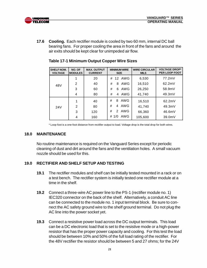
17.6 Cooling. Each rectifier module is cooled by two 60 mm, internal DC ballbearing fans. For proper cooling the area in front of the fans and around theair exits should be kept clear for unimpeded air flow.
Table 17-1 Minimum Output Copper Wire Sizes
* Loop foot is a one-foot distance from rectifier output to load. Voltage drop is the total drop for both wires.
18.0 MAINTENANCE
No routine maintenance is required on the Vanguard Series except for periodiccleaning of dust and dirt around the fans and the ventilation holes. A small vacuumnozzle should be used for this.
19.0 RECTIFIER AND SHELF SETUP AND TESTING
19.1 The rectifier modules and shelf can be initially tested mounted in a rack or ona test bench. The rectifier system is initially tested one rectifier module at atime in the shelf.
19.2 Connect a three-wire AC power line to the PS-1 (rectifier module no. 1)IEC320 connector on the back of the shelf. Alternatively, a conduit AC linecan be connected to the module no. 1 input terminal block. Be sure to con-nect the AC safety ground wire to the shelf ground terminal. Do not plug theAC line into the power socket yet.
19.3 Connect a resistive power load across the DC output terminals. This loadcan be a DC electronic load that is set to the resistive mode or a high-powerresistor that has the proper power capacity and cooling. For this test the loadshould be between 10% and 50% of the full load rating of the rectifier. Forthe 48V rectifier the resistor should be between 5 and 27 ohms; for the 24V
48V
SHELF NOM.VOLTAGE
NO. OFMODULES
1
2
3
4
20
40
60
80
MAX. OUTPUTCURRENT
MINIMUM WIRESIZE
# 12 AWG
# 8 AWG
# 6 AWG
# 4 AWG
WIRE CIRCULARMILS
6,530
16,510
26,250
41,740
VOLTAGE DROP*PER LOOP FOOT
77.2mV
62.2mV
58.9mV
49.3mV
24V
1
2
3
4
40
80
120
160
# 8 AWG
# 4 AWG
# 2 AWG
# 1/0 AWG
16,510
41,740
66,360
105,600
62.2mV
49.3mV
46.6mV
39.0mV

22
VANGUARD™ SERIESOPERATING MANUAL
rectifier it should be between 1.4 and 7 ohms.
19.4 Connect a color-coded, twisted pair (no. 22 or 24 AWG) from the remotesense pins to the load. The +Sense lead (J1 Pin 11) must go to the positiveside of the load and the - Sense lead (J1 Pin 23) must go to the negative sideof the load. Connect a wire from Remote Enable (J1 Pin 1) to SignalCommon (Pin 22). This connection must be made for the module tooperate.
19.5 Insert one of the rectifier modules into slot 1 of the shelf (leftmost slot.) Plugthe AC power in and measure the voltage across the load at the remotesense points with a digital voltmeter. The voltage should be approximately54.4V for a 48V rectifier or 27.2V for a 24V rectifier. If a different outputvoltage is desired, it should be set by means of the voltage adjustment poten-tiometer on the front panel.
19.6 Checking the Front Panel LEDs . The AC Good and DC Good LEDsshould both be green. The current monitor LED bar should be green inproportion to the output load current (20% of full load per LED).
19.7 Checking the Current Monitor Output. Measure the voltage at the Cur-rent Monitor output (J1 Pin 3 to - Sense Pin 23) with a digital voltmeter. Theoutput voltage should be approximately +0.2V per ampere of load current fora 48V module and approximately +0.1V per ampere for a 24V module.
19.8 Checking the Remote Enable Input. Next, disconnect the Remote Enablewire going from J1 Pin 1 to Pin 22. The rectifier output should turn off, givingzero volts across the load. The DC Good LED should go off.
19.9 Checking the AC Good and DC Good Outputs . Connect the - lead of anexternal 5V power supply to Signal Common (J1 Pin 22). Connect one endof a 2K resistor to the + lead of the 5V supply and the other end to the ACGood output (J1 Pin 14). Connect one end of another 2K resistor to the+ lead of the 5V supply and the other end to the DC Good output (J1 Pin 15).See Figure 10. Reconnect the Remote Enable wire. Measure the outputvoltage at both J1 Pins 14 and 15 with respect to Signal Common (Pin 22)with a digital voltmeter. Both voltages should be less than 0.5VDC, indicatinga TTL LO.
19.10 Checking the Remote Adjust Input . Connect a 200-ohm resistor and 200-ohm potentiometer to an external 5V power supply as shown in Figure 11.Connect the wiper arm of the pot to the Remote Adjust input, Pin 24. With

23
VANGUARD™ SERIESOPERATING MANUAL
Figure 11. Checking Remote Adjust Input
Figure 10. Checking AC Good and DC Good Outputs

24
VANGUARD™ SERIESOPERATING MANUAL
the voltage at the wiper arm set to zero, check the output voltage of the recti-fier module with a digital voltmeter. For a 48V unit it should be approximately40V and for a 24V unit it should be approximately 20V. Next, adjust the wiperarm to +2V and check the output voltage of the rectifier module. For a 48Vunit it should be approximately 58V and for a 24V unit it should be approxi-mately 29V. Unplug the external 5V supply and unplug the AC input to therectifier shelf.
19.11 Checking the Other Rectifier Modules. Each rectifier module should betested in the above manner to verify its operation. Go back to Section 19.5and proceed through the tests one by one until all rectifier modules have beenverified.
19.12 Checking the Complete Rectifier Shelf. Confirm that the output voltagesof the individual rectifier modules are all accurately set to 54.4 or 27.2 (for48V or 24V rectifier modules respectively) or to another required voltage. Thevoltages between modules should be set to within 50mV of each other forbest performance of the current sharing circuitry. Insert all rectifier modulesinto the shelf. Connect a power load - - high-power resistor or electronic loadin resistive mode -- in accordance with the table, to the output of the shelf.Connect the + and - Sense leads to + and - sides of the load, respectively, asin Section 19.4.
Table 19-1 Rectifier Shelf Loads For Test
Note that on the back of the shelf each rectifier module has its own AC powerconnection. For this test each rectifier should be connected to a separate 15AAC circuit. Plug the rectifier shelf into the AC power source.
Check the load voltage with a digital voltmeter. It should be very close to 54.4 or27.2VDC, depending on the model tested. The AC Good and DC Good LEDsshould both be green on each rectifier module. Two or three current monitorLEDs should be on for each module, depending on the value of the load current.
19”
19”
23”
23”
SHELF NO. RECT.MODULES
3
3
4
4
54.4
27.2
54.4
27.2
OUTPUTVOLTAGE
LOADCURRENT
30-40A
60-80A
50-60A
100-120A
LOADRESISTOR
1.36 - 1.81Ω0.34 - 0.45Ω0.91 - 1.09Ω0.23 - 0.27Ω

25
VANGUARD™ SERIESOPERATING MANUAL
Next, check the Current Monitor output voltage of each rectifier module. Themodules should be sharing the load current approximately equally. Measure thevoltage from pins 3, 5, 7 and 9 to the -Sense Pin 23. The voltages should all bewithin 10% of each other. Pin 9 is measured only for the four-module shelf.
While the shelf is operating, pull Module no. 1 out while monitoring the outputvoltage with a digital voltmeter. It should remain the same. Insert the moduleback into the shelf. Repeat this for each of the other modules. This test deter-mines that hot-swapping is functioning properly in the N+1 redundant mode.
With all the modules inserted into the shelf, check the Enable input for the entireshelf. Disconnect the Remote Enable wire going from J1 Pin 1 to Pin 22. Theshelf output should turn off and the output voltage go to zero. Reconnect theRemote Enable wire.
This completes the shelf setup and testing.
20.0 TROUBLE SHOOTING GUIDE
20.1 If you encounter difficulties in getting the rectifier modules or shelf to operateproperly, go through the following troubleshooting guide.
20.2 Table 20-1. Vanguard Rectifier Troubleshooting
No output, AC Goodand DC Good LEDsoff.
No output, DC GoodLED off, AC GoodLED on.
No output, DC GoodLED off, AC GoodLED on, LED BarGraph on
No output, DC GoodLED off, AC GoodLED on.
SYMPTOM POSSIBLE CAUSE
No input power.
Remote Enablein OFF mode.
Shorted output.
Overvoltageprotection(OVP) haslatched.
Check connection to AC source. Check ACsource circuit breakers.
Make sure J1 Pin 1 (Remote Enable) isconnected to Pin 22, Signal Common.
Check for short and remove.
Reset output by cycling the AC input OFFfor 20 seconds, and then back ON.
ACTION TO TAKE

26
VANGUARD™ SERIESOPERATING MANUAL
20.3 If none of the above actions solves the problem, call UNIPOWER Telecom954-346-2442 Ext. 400 for help and try to resolve the problem over the tele-phone.
No output, DC GoodLED off, AC GoodLED on.
No output, DC GoodLED off, AC GoodLED on, LED BarGraph on.
SYMPTOM POSSIBLE CAUSE
Overtemperatureprotection isactivated on oneor more rectifiermodules.
Output load istoo great for thenumber ofrectifier mod-ules.
Check the open collector Thermal Alarmoutput of each module for a logic HI oropen, indicating activated thermal protec-tion. Allow module to cool down for about10 minutes. It will then start up automati-cally. Check to see if the cooling fans areoperating.
Reduce load to proper level.
ACTION TO TAKE
Table 20-1. (Continued)
VManual6