Embed Size (px)
Citation preview

ValvesRotor Seals and Stators
Part No. For Valve Model No. Description
ETFE BLEND ROTOR SEALS7000-017 7000L, 7040L ETFE Rotor Seal
7010-071 7010, 7010-087, 7000, 7040 ETFE Rotor Seal
7030-015 7030 ETFE Rotor Seal
7060-074 7060, 7066, 9060 ETFE Rotor Seal
7060-067 7060L ETFE Rotor Seal
7125-079 7125, 7125-081, 7725 ETFE Rotor Seal
7410-075 7410 ETFE Rotor Seal
8125-097 8125 ETFE Rotor Seal
9010-051 9010 ETFE Rotor Seal
9125-082 9125, 9725 ETFE Rotor Seal
PEEK BLEND ROTOR SEALS3030-005 3030, 3030-038 PEEK Rotor Seal
3710-008 3000, 3000-038, 3710, 3710-038 PEEK Rotor Seal
3725-018 3725, 3725-038 PEEK Rotor Seal
9010-065 7010, 9010 PEEK Rotor Seal
8125-119 8125 PEEK Rotor Seal
9125-095 9125, 9725 PEEK Rotor Seal
STATORS FOR MX SERIES II MODULES7123-548 MXT715-000 Stator
7123-550 MXT715-105 Stator
7123-568 MXT715-102 Stator
7770-229 MXP7920-000 Stator
7980-004 MXP7980-000 Stator
7986-004 MXP7986-000 Stator
7900-146 MXP9900-000 Stator
7900-179 MXP7900-000 Stator
7900-183 MXP7970-000 Stator
7960-014 MXP7960-000 Stator
9960-002 MXP9960-000 Stator
STATORS FOR OTHER RHEODYNE VALVES3725-006 3725, 3710-038, 3000-038 and 3030-038 Stator
3725-085 3725-038, 3710-038, 3000-038 and 3030-038
Stator
7010-069 7000L, 7030L, 7040L Stator
7010-040 7010, 7125, 7000, 7030 and 7040 Stator
7010-066 7125-081 and 7010-087 Stator
7060-039 7060 and 7066 Stator
7060-065 7060L Stator
7123-047 PR/EV500-100 Stator
7123-127 PR/EV750-107 Stator
7123-128 PR/EV700-107 Stator
7123-142 PR/EV500-104 Stator
7123-145 PR/EV550-104 Stator
7123-147 PR/EV550-100 Stator
7123-148 PR/EV500-101 Stator
7123-149 PR/EV550-101 Stator
7123-180 PR703-100 and EV700-105 Stator
7123-221 PR753-100 and EV750-105 Stator
7123-223 PR/EV700-112 Stator
7123-390 EV200-102 Stator
7410-041 7410 and 7413 Stator
7520-030 (inlet) 7520 Stator
7520-035 (outlet) 7520 Stator
7650-002 PR/EV700-102 Stator
7725-010 7725(i) Stator
7750-070 7750 Stator
7750-038 PR/EV700-100 Stator
8125-098 8125 Stator
9060-016 9060 Stator
9125-043 9125, 9010, 9030 and 9725(i) Stator
9650-009 PR/EV750-102 Stator
9750-021 PR/EV750-100 Stator
Part No. For Valve Model No. Description
VESPEL BLEND ROTOR SEALS7000-016 7000L, 7040L Vespel Rotor Seal
7010-039 7010, 7000, 7040 Vespel Rotor Seal
7030-003 7030 Vespel Rotor Seal
7030-014 7030L Vespel Rotor Seal
7060-070 7060, 7066 Vespel Rotor Seal
7060-064 7060L Vespel Rotor Seal
7125-047 7125, 7725 Vespel Rotor Seal
7410-038 7410 Vespel Rotor Seal
7413-013 7413 Vespel Rotor Seal
8125-038 8125 Vespel Rotor Seal
Rotor Seals and StatorsThe rotor seal is the polymeric disc that makes a high pressure seal against the stator or stator face seal. The seal wears with use and is one of the only parts that may need routine replacement.
Stators are available in 316 stainless steel, PEEK™ and proprietary materials. Stators need replacement only if the ports or sealing surfaces become damaged. Avoid damage from use of improper injection needles by referring to the “Using Proper Syringe Needles” Application Note on page 139.
Please Note: Rotor seals for MX Series II™ Modules are available in RheBuild® Kits on page 135. Stators for MX Series II Modules are available on this page. MX (Series I) Module rotor seals are available in RheBuild Kits on page 135. Stators are available at www.idex-hs.com.
Top Seller SEE STARRED PRODUCTS
How to Select the Right Rotor SealThe standard rotor seal in many Rheodyne® manual valves is made from a Vespel® blend. This polyimide has low wear and high chemical resistance. Vespel tolerates a pH range of 0 to 10. Solutions more basic than pH 10 dissolve Vespel which damages the rotor seal. If you
use any solutions above pH 10, Rheodyne recommends a PEEK blend rotor seal. PEEK offers a high chemical resistance and versatility, and will tolerate the entire pH range from 0 to 14. ETFE blend rotor seals are appropriate for use in applications where PEEK is not generally acceptable, such as when methylene chloride or DMSO in higher concentrations is being used.
Application Note
Vespel ETFE PEEK

ValvesKits
Part No. Description
RHEBUILD KITS FOR MX SERIES II™ VALVES7150-999 RheBuild Kit for MXT715-000
7152-999 RheBuild Kit for MXT715-102
7155-999 RheBuild Kit for MXT715-105
7920-999 RheBuild Kit for MXP7920-000 and MXP7900-000
7960-999 RheBuild Kit for MXP9960-000
7961-999 RheBuild Kit for MXP7960-000
7970-999 RheBuild Kit for MXP7970-000
79801-999 RheBuild Kit for MXP7980-000
79861-999 RheBuild Kit for MXP7986-000
7900-999 RheBuild Kit for MXP9900-000
RHEBUILD KITS FOR MANUAL VALVES3725-999 RheBuild Kit for models 3725, 3725i, 3725-038, 3735i-038
7010-996 Conversion Kit including Stator Face Assembly for model 7010
7010-997 RheBuild Kit including Stator for model 7010
7010-999 RheBuild Kit for model 7010 and 7010-type Valves
7125-999 RheBuild Kit for models 7125 and 7126
7125Ti-999 RheBuild Kit for model 7125-081
7410-999 RheBuild Kit for model 7410
7520-999 RheBuild Kit for models 7520 and 7526
7725-999 RheBuild Kit for models 7725 and 7725i
8125-999 RheBuild Kit for models 8125 and 8126
9010-999 RheBuild Kit for model 9010
9125-999 RheBuild Kit for models 9125 and 9126
9725-999 RheBuild Kit for models 9725 and 9725i
RHEBUILD KITS FOR MX SERIES I™ VALVES7900-999 RheBuild Kit for models MX7900-000, MX7925-000,
MX9900-000, MX9925-000
7960-999 RheBuild Kit for model MX7960-000
7980-999 RheBuild Kit for model MX7980-000
7984-999 RheBuild Kit for model MX7984-000
7986-999 RheBuild Kit for model MX7986-000
RHEBUILD KITS FOR LABPRO™ & EV AUTOMATED FLUIDIC INSTRUMENTS1001-999 RheBuild Kit for model PR100-101
1005-999 RheBuild Kit for model PR/EV100-105
1006-999 RheBuild Kit for model PR/EV100-106
5001-999 RheBuild Kit for models PR/EV500-101 and PR/EV550-101
5100-999 RheBuild Kit for models PR/EV500-100 and PR/EV550-100
5104-999 RheBuild Kit for models PR/EV500-104 and PR/EV550-104
7004-999 RheBuild Kit for models PR/EV700-104 and PR/EV750-104
7112-999 RheBuild Kit for models PR/EV700-112 and PR/EV750-112
7501-999 RheBuild Kit for models PR/EV700-100 and PR/EV750-100
7502-999 RheBuild Kit for models PR/EV700-102 and PR/EV750-102
7507-999 RheBuild Kit for models PR/EV700-107 and PR/EV750-107
7531-999 RheBuild Kit for models PR703-100 and PR753-100
RheBuild® KitsRheBuild Kits are available for all Rheodyne® brand products. Included in each individualized RheBuild Kit are all parts, tools, and instructions to maintain precision performance of your particular product. RheBuild Kits eliminate individual part ordering.
Figure 1 Air present in the needle port tube is pushed by the syringe during loading into the sample loop
Figure 2 Pathway of the flushing mobile phase using the Needle Port Cleaner, Part # 7125-054 (see page 139) when the injector is in INJECT
Air
How to Avoid Pressure TransientsAir in the sample loop can cause an instantaneous system pressure drop that eventually returns to a normal level. Air causes the pressure to drop when the injector moves from the LOAD to the INJECT position. When large sample loops (≥100 µL) are partially loaded, air present in the needle port tube is pushed into the sample loop (see Figure 1). Air can also enter the sample loop from siphoning which occurs when the vent line is higher than the injection port. In either case, upon injection, the system pressure collapses the air bubble, causing pressure to drop momentarily.
A pressure drop in the system caused by air results in changes in retention time, artifact peaks, and affects column performance.
Avoid pressure drops by removing the air in the needle port tube. Do this by flushing about 1 mL of mobile phase with a luer syringe with needle port cleaner. Keep the needle port tube filled with mobile phase by occasional flushing. Adjust the vent line(s) so the outlet is at the same horizontal level as the needle port (see Figure 2). For additional injection troubleshooting, refer to the Rheodyne Troubleshooting Guide for HPLC Injection Problems. You may download the Guide from the IDEX Health & Science web site: www.idex-hs.com under Support.
Application Note
Order Online WWW. IDEX-HS.COM
Valves
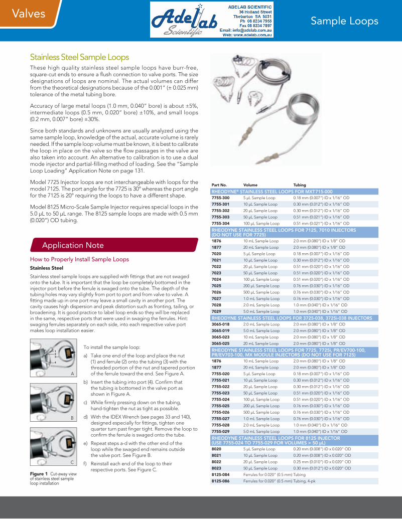
Stainless Steel Sample LoopsThese high quality stainless steel sample loops have burr-free, square-cut ends to ensure a flush connection to valve ports. The size designations of loops are nominal. The actual volumes can differ from the theoretical designations because of the 0.001” (± 0.025 mm) tolerance of the metal tubing bore.
Accuracy of large metal loops (1.0 mm, 0.040” bore) is about ±5%, intermediate loops (0.5 mm, 0.020” bore) ±10%, and small loops (0.2 mm, 0.007” bore) ±30%.
Since both standards and unknowns are usually analyzed using the same sample loop, knowledge of the actual, accurate volume is rarely needed. If the sample loop volume must be known, it is best to calibrate the loop in place on the valve so the flow passages in the valve are also taken into account. An alternative to calibration is to use a dual mode injector and partial-filling method of loading. See the “Sample Loop Loading” Application Note on page 131.
Model 7725 Injector loops are not interchangeable with loops for the model 7125. The port angle for the 7725 is 30° whereas the port angle for the 7125 is 20° requiring the loops to have a different shape.
Model 8125 Micro-Scale Sample Injector requires special loops in the 5.0 µL to 50 µL range. The 8125 sample loops are made with 0.5 mm (0.020”) OD tubing.
Sample Loops
Part No. Volume Tubing
RHEODYNE® STAINLESS STEEL LOOPS FOR MXT715-0007755-300 5 µL Sample Loop 0.18 mm (0.007”) ID x 1/16” OD
7755-301 10 µL Sample Loop 0.30 mm (0.012”) ID x 1/16” OD
7755-302 20 µL Sample Loop 0.30 mm (0.012”) ID x 1/16” OD
7755-303 50 µL Sample Loop 0.51 mm (0.021”) ID x 1/16” OD
7755-304 100 µL Sample Loop 0.51 mm (0.021”) ID x 1/16” OD
RHEODYNE STAINLESS STEEL LOOPS FOR 7125, 7010 INJECTORS (DO NOT USE FOR 7725)1876 10 mL Sample Loop 2.0 mm (0.080”) ID x 1/8” OD
1877 20 mL Sample Loop 2.0 mm (0.080”) ID x 1/8” OD
7020 5 µL Sample Loop 0.18 mm (0.007”) ID x 1/16” OD
7021 10 µL Sample Loop 0.30 mm (0.012”) ID x 1/16” OD
7022 20 µL Sample Loop 0.51 mm (0.020”) ID x 1/16” OD
7023 50 µL Sample Loop 0.51 mm (0.020”) ID x 1/16” OD
7024 100 µL Sample Loop 0.51 mm (0.020”) ID x 1/16” OD
7025 200 µL Sample Loop 0.76 mm (0.030”) ID x 1/16” OD
7026 500 µL Sample Loop 0.76 mm (0.030”) ID x 1/16” OD
7027 1.0 mL Sample Loop 0.76 mm (0.030”) ID x 1/16” OD
7028 2.0 mL Sample Loop 1.0 mm (0.040”) ID x 1/16” OD
7029 5.0 mL Sample Loop 1.0 mm (0.040”) ID x 1/16” OD
RHEODYNE STAINLESS STEEL LOOPS FOR 3725-038, 3725i-038 INJECTORS3065-018 2.0 mL Sample Loop 2.0 mm (0.080”) ID x 1/8” OD
3065-019 5.0 mL Sample Loop 2.0 mm (0.080”) ID x 1/8” OD
3065-023 10 mL Sample Loop 2.0 mm (0.080”) ID x 1/8” OD
3065-025 20 mL Sample Loop 2.0 mm (0.080”) ID x 1/8” OD
RHEODYNE STAINLESS STEEL LOOPS FOR 7725, 7725i, PR/EV700-100, PR/EV703-100, MX MODULE INJECTORS (DO NOT USE FOR 7125)1876 10 mL Sample Loop 2.0 mm (0.080”) ID x 1/8” OD
1877 20 mL Sample Loop 2.0 mm (0.080”) ID x 1/8” OD
7755-020 5 µL Sample Loop 0.18 mm (0.007”) ID x 1/16” OD
7755-021 10 µL Sample Loop 0.30 mm (0.012”) ID x 1/16” OD
7755-022 20 µL Sample Loop 0.30 mm (0.012”) ID x 1/16” OD
7755-023 50 µL Sample Loop 0.51 mm (0.020”) ID x 1/16” OD
7755-024 100 µL Sample Loop 0.51 mm (0.020”) ID x 1/16” OD
7755-025 200 µL Sample Loop 0.76 mm (0.030”) ID x 1/16” OD
7755-026 500 µL Sample Loop 0.76 mm (0.030”) ID x 1/16” OD
7755-027 1.0 mL Sample Loop 0.76 mm (0.030”) ID x 1/16” OD
7755-028 2.0 mL Sample Loop 1.0 mm (0.040”) ID x 1/16” OD
7755-029 5.0 mL Sample Loop 1.0 mm (0.040”) ID x 1/16” OD
RHEODYNE STAINLESS STEEL LOOPS FOR 8125 INJECTOR (USE 7755-024 TO 7755-029 FOR VOLUMES > 50 µL)8020 5 µL Sample Loop 0.20 mm (0.008”) ID x 0.020” OD
8021 10 µL Sample Loop 0.20 mm (0.008”) ID x 0.020” OD
8022 20 µL Sample Loop 0.25 mm (0.010”) ID x 0.020” OD
8023 50 µL Sample Loop 0.30 mm (0.012”) ID x 0.020” OD
8125-084 Ferrules for 0.020” (0.5 mm) Tubing
8125-086 Ferrules for 0.020” (0.5 mm) Tubing, 4-pk
Application Note
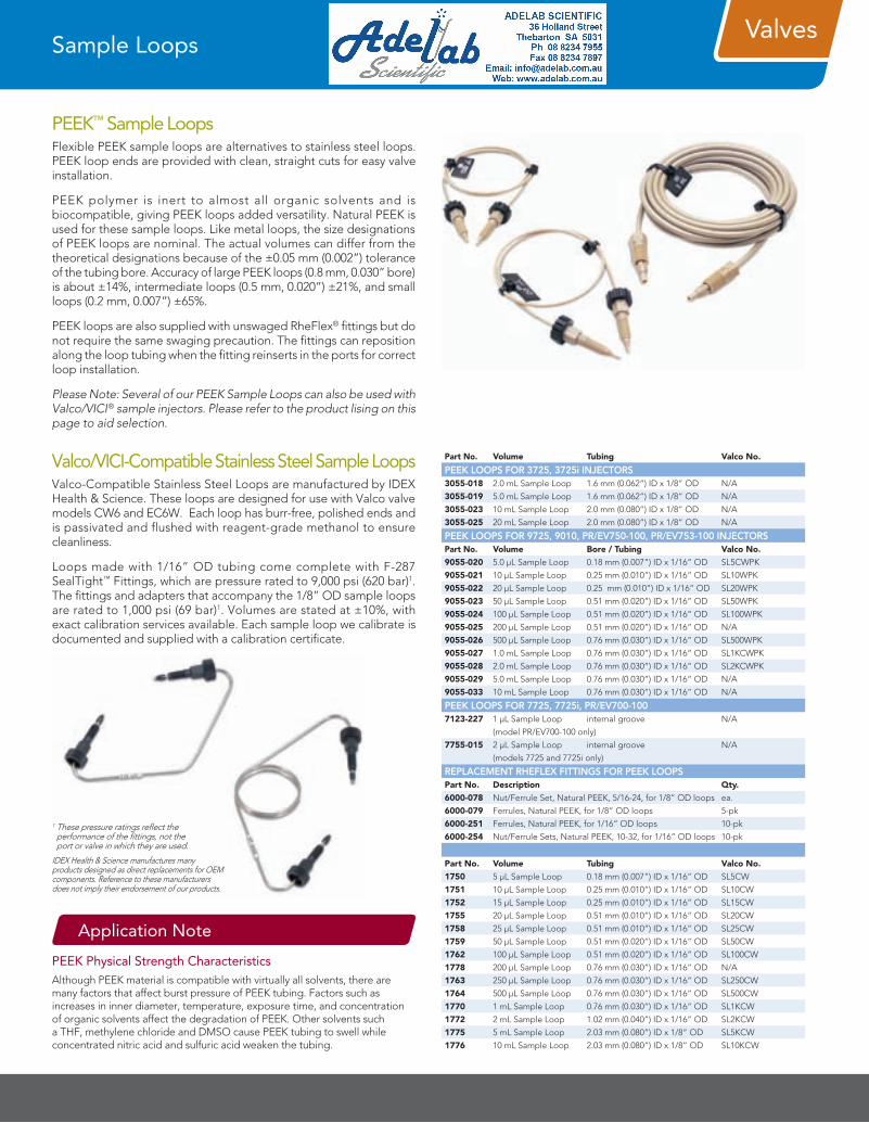
How to Properly Install Sample LoopsStainless Steel
Stainless steel sample loops are supplied with fittings that are not swaged onto the tube. It is important that the loop be completely bottomed in the injector port before the ferrule is swaged onto the tube. The depth of the tubing holes may vary slightly from port to port and from valve to valve. A fitting made up in one port may leave a small cavity in another port. The cavity causes high dispersion and peak distortion such as fronting, tailing, or broadening. It is good practice to label loop ends so they will be replaced in the same, respective ports that were used in swaging the ferrules. Hint: swaging ferrules separately on each side, into each respective valve port makes loop installation easier.
To install the sample loop:
a) Take one end of the loop and place the nut (1) and ferrule (2) onto the tubing (3) with the threaded portion of the nut and tapered portion of the ferrule toward the end. See Figure A.
b) Insert the tubing into port (4). Confirm that the tubing is bottomed in the valve port as shown in Figure A.
c) While firmly pressing down on the tubing, hand-tighten the nut as tight as possible.
d) With the IDEX Wrench (see pages 33 and 140), designed especially for fittings, tighten one quarter turn past finger tight. Remove the loop to confirm the ferrule is swaged onto the tube.
e) Repeat steps a-d with the other end of the loop while the swaged end remains outside the valve port. See Figure B.
f) Reinstall each end of the loop to their respective ports. See Figure C.
A
C
B
Figure 1 Cut-away view of stainless steel sample loop installation
Valves
Valco/VICI-Compatible Stainless Steel Sample LoopsValco-Compatible Stainless Steel Loops are manufactured by IDEX Health & Science. These loops are designed for use with Valco valve models CW6 and EC6W. Each loop has burr-free, polished ends and is passivated and flushed with reagent-grade methanol to ensure cleanliness.
Loops made with 1/16” OD tubing come complete with F-287 SealTight™ Fittings, which are pressure rated to 9,000 psi (620 bar)1. The fittings and adapters that accompany the 1/8” OD sample loops are rated to 1,000 psi (69 bar)1. Volumes are stated at ±10%, with exact calibration services available. Each sample loop we calibrate is documented and supplied with a calibration certificate.
Sample Loops
PEEK™ Sample LoopsFlexible PEEK sample loops are alternatives to stainless steel loops. PEEK loop ends are provided with clean, straight cuts for easy valve installation.
PEEK polymer is inert to almost all organic solvents and is biocompatible, giving PEEK loops added versatility. Natural PEEK is used for these sample loops. Like metal loops, the size designations of PEEK loops are nominal. The actual volumes can differ from the theoretical designations because of the ±0.05 mm (0.002”) tolerance of the tubing bore. Accuracy of large PEEK loops (0.8 mm, 0.030” bore) is about ±14%, intermediate loops (0.5 mm, 0.020”) ±21%, and small loops (0.2 mm, 0.007”) ±65%.
PEEK loops are also supplied with unswaged RheFlex® fittings but do not require the same swaging precaution. The fittings can reposition along the loop tubing when the fitting reinserts in the ports for correct loop installation.
Please Note: Several of our PEEK Sample Loops can also be used with Valco/VICI® sample injectors. Please refer to the product lising on this page to aid selection.
Part No. Volume Tubing Valco No.
PEEK LOOPS FOR 3725, 3725i INJECTORS3055-018 2.0 mL Sample Loop 1.6 mm (0.062”) ID x 1/8” OD N/A
3055-019 5.0 mL Sample Loop 1.6 mm (0.062”) ID x 1/8” OD N/A
3055-023 10 mL Sample Loop 2.0 mm (0.080”) ID x 1/8” OD N/A
3055-025 20 mL Sample Loop 2.0 mm (0.080”) ID x 1/8” OD N/A
PEEK LOOPS FOR 9725, 9010, PR/EV750-100, PR/EV753-100 INJECTORSPart No. Volume Bore / Tubing Valco No.
9055-020 5.0 µL Sample Loop 0.18 mm (0.007”) ID x 1/16” OD SL5CWPK
9055-021 10 µL Sample Loop 0.25 mm (0.010”) ID x 1/16” OD SL10WPK
9055-022 20 µL Sample Loop 0.25 mm (0.010”) ID x 1/16” OD SL20WPK
9055-023 50 µL Sample Loop 0.51 mm (0.020”) ID x 1/16” OD SL50WPK
9055-024 100 µL Sample Loop 0.51 mm (0.020”) ID x 1/16” OD SL100WPK
9055-025 200 µL Sample Loop 0.51 mm (0.020”) ID x 1/16” OD N/A
9055-026 500 µL Sample Loop 0.76 mm (0.030”) ID x 1/16” OD SL500WPK
9055-027 1.0 mL Sample Loop 0.76 mm (0.030”) ID x 1/16” OD SL1KCWPK
9055-028 2.0 mL Sample Loop 0.76 mm (0.030”) ID x 1/16” OD SL2KCWPK
9055-029 5.0 mL Sample Loop 0.76 mm (0.030”) ID x 1/16” OD N/A
9055-033 10 mL Sample Loop 0.76 mm (0.030”) ID x 1/16” OD N/A
PEEK LOOPS FOR 7725, 7725i, PR/EV700-100 7123-227 1 µL Sample Loop internal groove N/A
(model PR/EV700-100 only)
7755-015 2 µL Sample Loop internal groove N/A
(models 7725 and 7725i only)
REPLACEMENT RHEFLEX FITTINGS FOR PEEK LOOPSPart No. Description Qty.
6000-078 Nut/Ferrule Set, Natural PEEK, 5/16-24, for 1/8” OD loops ea.
6000-079 Ferrules, Natural PEEK, for 1/8” OD loops 5-pk
6000-251 Ferrules, Natural PEEK, for 1/16” OD loops 10-pk
6000-254 Nut/Ferrule Sets, Natural PEEK, 10-32, for 1/16” OD loops 10-pk
Part No. Volume Tubing Valco No.
1750 5 µL Sample Loop 0.18 mm (0.007”) ID x 1/16” OD SL5CW
1751 10 µL Sample Loop 0.25 mm (0.010”) ID x 1/16” OD SL10CW
1752 15 µL Sample Loop 0.25 mm (0.010”) ID x 1/16” OD SL15CW
1755 20 µL Sample Loop 0.51 mm (0.010”) ID x 1/16” OD SL20CW
1758 25 µL Sample Loop 0.51 mm (0.010”) ID x 1/16” OD SL25CW
1759 50 µL Sample Loop 0.51 mm (0.020”) ID x 1/16” OD SL50CW
1762 100 µL Sample Loop 0.51 mm (0.020”) ID x 1/16” OD SL100CW
1778 200 µL Sample Loop 0.76 mm (0.030”) ID x 1/16” OD N/A
1763 250 µL Sample Loop 0.76 mm (0.030”) ID x 1/16” OD SL250CW
1764 500 µL Sample Loop 0.76 mm (0.030”) ID x 1/16” OD SL500CW
1770 1 mL Sample Loop 0.76 mm (0.030”) ID x 1/16” OD SL1KCW
1772 2 mL Sample Loop 1.02 mm (0.040”) ID x 1/16” OD SL2KCW
1775 5 mL Sample Loop 2.03 mm (0.080”) ID x 1/8” OD SL5KCW
1776 10 mL Sample Loop 2.03 mm (0.080”) ID x 1/8” OD SL10KCW
Application Note
PEEK Physical Strength CharacteristicsAlthough PEEK material is compatible with virtually all solvents, there are many factors that affect burst pressure of PEEK tubing. Factors such as increases in inner diameter, temperature, exposure time, and concentration of organic solvents affect the degradation of PEEK. Other solvents such a THF, methylene chloride and DMSO cause PEEK tubing to swell while concentrated nitric acid and sulfuric acid weaken the tubing.
1 These pressure ratings reflect the performance of the fittings, not the port or valve in which they are used.
IDEX Health & Science manufactures many products designed as direct replacements for OEM components. Reference to these manufacturers does not imply their endorsement of our products.
Valves
Application Note Application Note
Application Notes
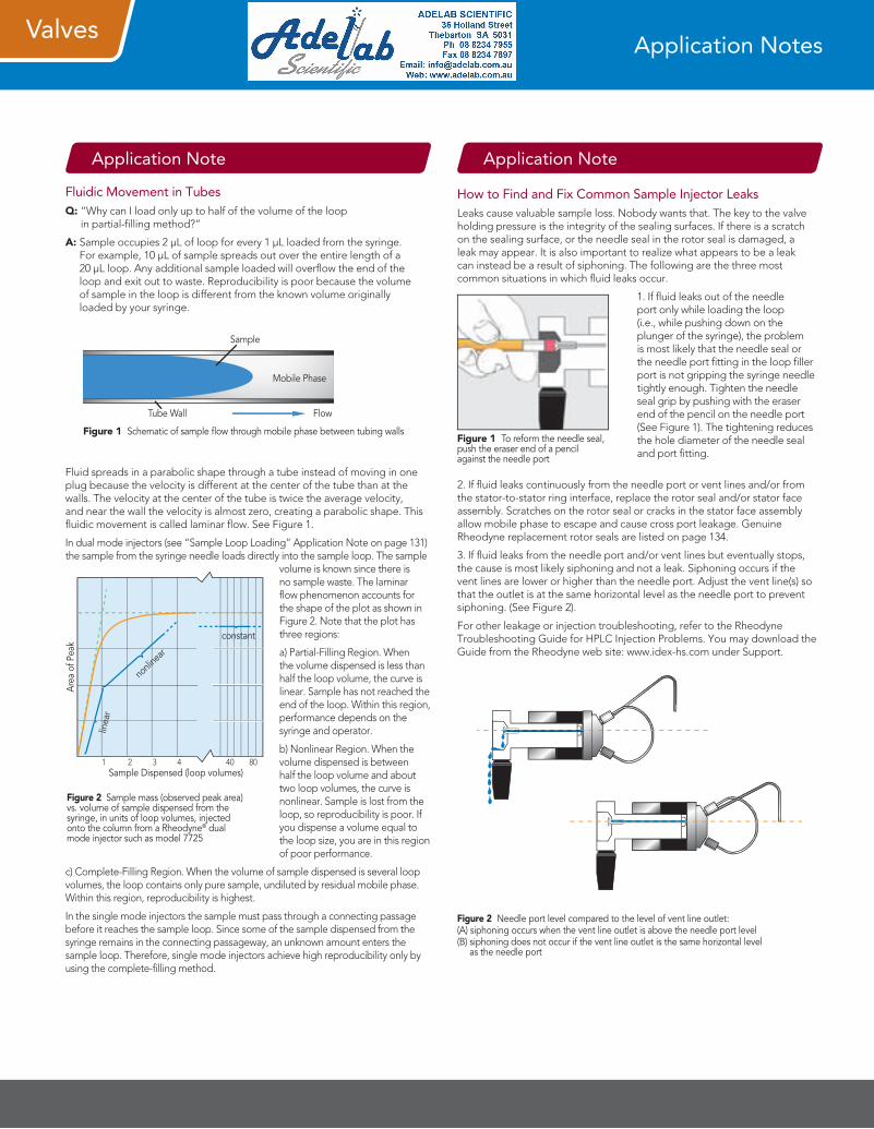
Fluidic Movement in TubesQ: “Why can I load only up to half of the volume of the loop
in partial-filling method?”
A: Sample occupies 2 µL of loop for every 1 µL loaded from the syringe. For example, 10 µL of sample spreads out over the entire length of a 20 µL loop. Any additional sample loaded will overflow the end of the loop and exit out to waste. Reproducibility is poor because the volume of sample in the loop is different from the known volume originally loaded by your syringe.
Fluid spreads in a parabolic shape through a tube instead of moving in one plug because the velocity is different at the center of the tube than at the walls. The velocity at the center of the tube is twice the average velocity, and near the wall the velocity is almost zero, creating a parabolic shape. This fluidic movement is called laminar flow. See Figure 1.
In dual mode injectors (see “Sample Loop Loading” Application Note on page 131) the sample from the syringe needle loads directly into the sample loop. The sample
volume is known since there is no sample waste. The laminar flow phenomenon accounts for the shape of the plot as shown in Figure 2. Note that the plot has three regions:
a) Partial-Filling Region. When the volume dispensed is less than half the loop volume, the curve is linear. Sample has not reached the end of the loop. Within this region, performance depends on the syringe and operator.
b) Nonlinear Region. When the volume dispensed is between half the loop volume and about two loop volumes, the curve is nonlinear. Sample is lost from the loop, so reproducibility is poor. If you dispense a volume equal to the loop size, you are in this region of poor performance.
c) Complete-Filling Region. When the volume of sample dispensed is several loop volumes, the loop contains only pure sample, undiluted by residual mobile phase. Within this region, reproducibility is highest.
In the single mode injectors the sample must pass through a connecting passage before it reaches the sample loop. Since some of the sample dispensed from the syringe remains in the connecting passageway, an unknown amount enters the sample loop. Therefore, single mode injectors achieve high reproducibility only by using the complete-filling method.
Sample
FlowTube Wall
Mobile Phase
Figure 1 Schematic of sample flow through mobile phase between tubing walls
Area
of P
eak
Sample Dispensed (loop volumes) 1 2 3 4 40 80
linea
r
nonli
near
constant
Figure 2 Sample mass (observed peak area) vs. volume of sample dispensed from the syringe, in units of loop volumes, injected onto the column from a Rheodyne® dual mode injector such as model 7725
How to Find and Fix Common Sample Injector LeaksLeaks cause valuable sample loss. Nobody wants that. The key to the valve holding pressure is the integrity of the sealing surfaces. If there is a scratch on the sealing surface, or the needle seal in the rotor seal is damaged, a leak may appear. It is also important to realize what appears to be a leak can instead be a result of siphoning. The following are the three most common situations in which fluid leaks occur.
1. If fluid leaks out of the needle port only while loading the loop (i.e., while pushing down on the plunger of the syringe), the problem is most likely that the needle seal or the needle port fitting in the loop filler port is not gripping the syringe needle tightly enough. Tighten the needle seal grip by pushing with the eraser end of the pencil on the needle port (See Figure 1). The tightening reduces the hole diameter of the needle seal and port fitting.
2. If fluid leaks continuously from the needle port or vent lines and/or from the stator-to-stator ring interface, replace the rotor seal and/or stator face assembly. Scratches on the rotor seal or cracks in the stator face assembly allow mobile phase to escape and cause cross port leakage. Genuine Rheodyne replacement rotor seals are listed on page 134.
3. If fluid leaks from the needle port and/or vent lines but eventually stops, the cause is most likely siphoning and not a leak. Siphoning occurs if the vent lines are lower or higher than the needle port. Adjust the vent line(s) so that the outlet is at the same horizontal level as the needle port to prevent siphoning. (See Figure 2).
For other leakage or injection troubleshooting, refer to the Rheodyne Troubleshooting Guide for HPLC Injection Problems. You may download the Guide from the Rheodyne web site: www.idex-hs.com under Support.
Figure 1 To reform the needle seal, push the eraser end of a pencil against the needle port
Figure 2 Needle port level compared to the level of vent line outlet:(A) siphoning occurs when the vent line outlet is above the needle port level (B) siphoning does not occur if the vent line outlet is the same horizontal level
as the needle port
Valves
Application Note
Adapters for Syringe Needles
Needle Port AccessoriesThe Rheodyne® adaptable Loop Filler Ports (Part #7012 and 9012) are used to load sample from syringe needles or luer tips. The Needle Port (Part #9013) conserves sample by minimizing the volume between the needle and the valve.
9125-076
7125-054
9012
9013
7012
Valve Adapter for 10-32 Ports For 1/32” OD stainless steel tubing Low swept volume Extends the life of the rotor
As a result of customer requests, a Valve Adapter for 10-32 ports was designed specifically for use with 1/32” OD stainless steel tubing. This product extends the life of and prevents damage to the rotor, guarding against such potential hazards as tubing that may pass through the stator and scratch the rotor. This adapter has a very low swept volume, at 300 nL. The all-PEEK™ fluid pathway ensures biocompatibility.
M-400Valve Adapter(Includes indicated products)
Tubing Seal Ferrule Assembly Micro Seal
P-416 Nut
1/32” OD Tubing(not included)
F-112Micro Ferrule
MicroFilter Body
M-400
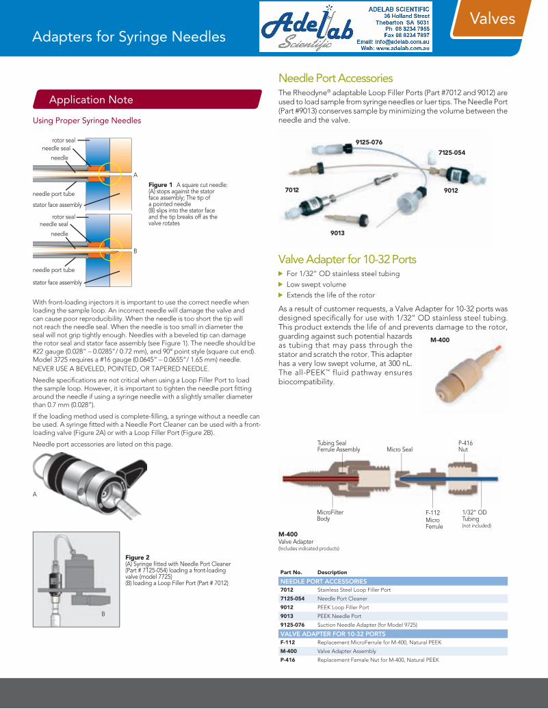
Using Proper Syringe Needles
With front-loading injectors it is important to use the correct needle when loading the sample loop. An incorrect needle will damage the valve and can cause poor reproducibility. When the needle is too short the tip will not reach the needle seal. When the needle is too small in diameter the seal will not grip tightly enough. Needles with a beveled tip can damage the rotor seal and stator face assembly (see Figure 1). The needle should be #22 gauge (0.028” – 0.0285”/ 0.72 mm), and 90° point style (square cut end). Model 3725 requires a #16 gauge (0.0645” – 0.0655”/ 1.65 mm) needle. NEVER USE A BEVELED, POINTED, OR TAPERED NEEDLE.
Needle specifications are not critical when using a Loop Filler Port to load the sample loop. However, it is important to tighten the needle port fitting around the needle if using a syringe needle with a slightly smaller diameter than 0.7 mm (0.028”).
If the loading method used is complete-filling, a syringe without a needle can be used. A syringe fitted with a Needle Port Cleaner can be used with a front-loading valve (Figure 2A) or with a Loop Filler Port (Figure 2B).
Needle port accessories are listed on this page.
Figure 1 A square cut needle: (A) stops against the stator face assembly; The tip of a pointed needle (B) slips into the stator face and the tip breaks off as the valve rotates
A
B
rotor sealneedle seal
needle
needle port tube
stator face assembly
rotor sealneedle seal
needle
needle port tube
stator face assembly
A
Figure 2 (A) Syringe fitted with Needle Port Cleaner (Part # 7125-054) loading a front-loading valve (model 7725) (B) loading a Loop Filler Port (Part # 7012)
B
Part No. Description
NEEDLE PORT ACCESSORIES7012 Stainless Steel Loop Filler Port
7125-054 Needle Port Cleaner
9012 PEEK Loop Filler Port
9013 PEEK Needle Port
9125-076 Suction Needle Adapter (for Model 9725)
VALVE ADAPTER FOR 10-32 PORTSF-112 Replacement MicroFerrule for M-400, Natural PEEK
M-400 Valve Adapter Assembly
P-416 Replacement Female Nut for M-400, Natural PEEK
ValvesValve Accessories
IDEX WrenchThe smartly designed IDEX Wrench is a double-ended slotted socket wrench that fits over 1/16” and 1/8” OD tubing. It easily loosens and tightens 1/4” and 5/16” hex head stainless steel or PEEK™ fittings. The “Z” shape of the IDEX Wrench provides ideal leverage for changing sample loops and fittings, and keeps one end from restricting the use of the other.
6810
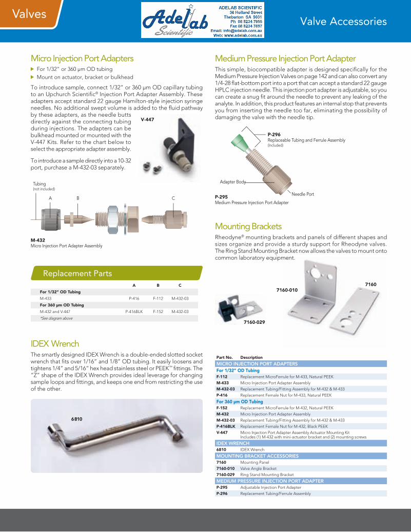
Micro Injection Port Adapters For 1/32” or 360 µm OD tubing Mount on actuator, bracket or bulkhead
To introduce sample, connect 1/32” or 360 µm OD capillary tubing to an Upchurch Scientific® Injection Port Adapter Assembly. These adapters accept standard 22 gauge Hamilton-style injection syringe needles. No additional swept volume is added to the fluid pathway by these adapters, as the needle butts directly against the connecting tubing during injections. The adapters can be bulkhead mounted or mounted with the V-447 Kits. Refer to the chart below to select the appropriate adapter assembly.
To introduce a sample directly into a 10-32 port, purchase a M-432-03 separately.
V-447
M-432Micro Injection Port Adapter Assembly
A B C
Tubing(not included)
Part No. Description
MICRO INJECTION PORT ADAPTERSFor 1/32” OD TubingF-112 Replacement MicroFerrule for M-433, Natural PEEK
M-433 Micro Injection Port Adapter Assembly
M-432-03 Replacement Tubing/Fitting Assembly for M-432 & M-433
P-416 Replacement Female Nut for M-433, Natural PEEK
For 360 µm OD TubingF-152 Replacement MicroFerrule for M-432, Natural PEEK
M-432 Micro Injection Port Adapter Assembly
M-432-03 Replacement Tubing/Fitting Assembly for M-432 & M-433
P-416BLK Replacement Female Nut for M-432, Black PEEK
V-447 Micro Injection Port Adapter Assembly Actuator Mounting Kit Includes (1) M-432 with mini-actuator bracket and (2) mounting screws
IDEX WRENCH6810 IDEX Wrench
MOUNTING BRACKET ACCESSORIES7160 Mounting Panel
7160-010 Valve Angle Bracket
7160-029 Ring Stand Mounting Bracket
MEDIUM PRESSURE INJECTION PORT ADAPTERP-295 Adjustable Injection Port Adapter
P-296 Replacement Tubing/Ferrule Assembly
A B C
For 1/32” OD Tubing
M-433 P-416 F-112 M-432-03
For 360 µm OD Tubing
M-432 and V-447 P-416BLK F-152 M-432-03
*See diagram above
Replacement Parts
P-295Medium Pressure Injection Port Adapter
P-296Replaceable Tubing and Ferrule Assembly(Included)
Adapter Body
Needle Port
Medium Pressure Injection Port AdapterThis simple, biocompatible adapter is designed specifically for the Medium Pressure Injection Valves on page 142 and can also convert any 1/4-28 flat-bottom port into a port that can accept a standard 22 gauge HPLC injection needle. This injection port adapter is adjustable, so you can create a snug fit around the needle to prevent any leaking of the analyte. In addition, this product features an internal stop that prevents you from inserting the needle too far, eliminating the possibility of damaging the valve with the needle tip.
7160
7160-029
7160-010
Mounting BracketsRheodyne® mounting brackets and panels of different shapes and sizes organize and provide a sturdy support for Rheodyne valves. The Ring Stand Mounting Bracket now allows the valves to mount onto common laboratory equipment.