Embed Size (px)
Citation preview

DOE Fundamentals
MECHANICAL SCIENCE
Module 4
Valves

Mechanical Science Valves
ME-04-i
TABLE OF CONTENTS
TABLE OF CONTENTS ............................................................................................................... i
LIST OF FIGURES .................................................................................................................... iv
LIST OF TABLES ....................................................................................................................... vi
REFERENCES ......................................................................................................................... vii
OBJECTIVES .......................................................................................................................... viii
VALVE FUNCTIONS AND BASIC PARTS ................................................................................. 1
Introduction ............................................................................................................................ 1
Valve Body ............................................................................................................................. 2
Valve Bonnet .......................................................................................................................... 2
Valve Trim .............................................................................................................................. 3
Valve Actuator ........................................................................................................................ 5
Valve Packing ......................................................................................................................... 5
Introduction to the Types of Valves ......................................................................................... 6
Summary ................................................................................................................................ 7
TYPES OF VALVES .................................................................................................................. 8
Gate Valves ............................................................................................................................ 8
Gate Valve Disk Design .........................................................................................................10
Gate Valve Stem Design .......................................................................................................13
Gate Valve Seat Design ........................................................................................................13
Globe Valves .........................................................................................................................14
Globe Valve Body Designs ....................................................................................................15
Globe Valve Disks .................................................................................................................16
Globe Valve Disk and Stem Connections ..............................................................................17
Globe Valve Seats .................................................................................................................17
Globe Valve Direction of Flow ...............................................................................................17
Ball Valves ............................................................................................................................17
Ball Valve Stem Design .........................................................................................................19
Ball Valve Bonnet Design ......................................................................................................19
Ball Valve Position .................................................................................................................19
Plug Valves ...........................................................................................................................19
Mechanical Science Valves
ME-04-ii
Plug Ports ..............................................................................................................................20
Multiport Plug Valves .............................................................................................................21
Plug Valve Disks ...................................................................................................................21
Lubricated Plug Valve Design ................................................................................................21
Non-lubricated Plugs .............................................................................................................22
Manually Operated Plug Valve Installation ............................................................................22
Plug Valve Glands .................................................................................................................22
Diaphragm Valves .................................................................................................................23
Diaphragm Construction ........................................................................................................23
Diaphragm Valve Stem Assemblies .......................................................................................25
Diaphragm Valve Bonnet Assemblies ....................................................................................25
Reducing Valves ...................................................................................................................26
Pinch Valves..........................................................................................................................28
Pinch Valve Bodies................................................................................................................29
Butterfly Valve Seat Construction ..........................................................................................30
Butterfly Valve Body Construction .........................................................................................30
Butterfly Valve Disk and Stem Assemblies ............................................................................30
Needle Valves .......................................................................................................................31
Needle Valve Applications .....................................................................................................31
Needle Valve Body Designs ..................................................................................................31
Check Valves ........................................................................................................................32
Swing Check Valves ..............................................................................................................32
Tilting Disk Check Valves ......................................................................................................33
Lift Check Valves ...................................................................................................................34
Piston Check Valves ..............................................................................................................35
Butterfly Check Valves ..........................................................................................................36
Relief and Safety Valves .......................................................................................................37
Pilot-Operated Relief Valves ..................................................................................................39
VALVE ACTUATORS ...............................................................................................................41
Introduction ...........................................................................................................................41
Manual, Fixed, and Hammer Actuators..................................................................................41
Handwheels Fixed to Stem ....................................................................................................41
Hammer Handwheel ..............................................................................................................42

Mechanical Science Valves
ME-04-iii
Gears ....................................................................................................................................42
Electric Motor Actuators ........................................................................................................43
Pneumatic Actuators .............................................................................................................44
Hydraulic Actuators ...............................................................................................................44
Self-Actuated Valves .............................................................................................................45
Solenoid Actuated Valves ......................................................................................................45
Speed of Power Actuators .....................................................................................................46
Valve Position Indication .......................................................................................................46
Summary ...............................................................................................................................47

Mechanical Science Valves
ME-04-iv
LIST OF FIGURES
Figure 1 Basic Parts of a Valve ........................................................................................ 2
Figure 2 Rising Stems ...................................................................................................... 4
Figure 3 Non-rising Stems ............................................................................................... 5
Figure 4 Gate Valve ......................................................................................................... 9
Figure 5 Solid Wedge Gate Valve .................................................................................. 10
Figure 6 Flexible Wedge Gate Valve .............................................................................. 11
Figure 7 Split Wedge Gate Valve ................................................................................... 11
Figure 8 Parallel Disk Gate Valve .................................................................................. 12
Figure 9 Z-Body Globe Valve ......................................................................................... 14
Figure 10 Y-Body Globe Valve ......................................................................................... 15
Figure 11 Angle Globe Valve ........................................................................................... 16
Figure 12 Typical Ball Valve ............................................................................................. 18
Figure 13 Plug Valve ........................................................................................................ 20
Figure 14 Straight-Through Diaphragm Valve .................................................................. 23
Figure 15 Weir Diaphragm Valve ..................................................................................... 24
Figure 16 Variable Reducing Valve .................................................................................. 26
Figure 17 Non-Variable Reducing Valve .......................................................................... 27
Figure 18 Pinch Valves .................................................................................................... 28
Figure 19 Typical Butterfly Valve ...................................................................................... 29
Figure 20 Needle Valve ................................................................................................... 31
Figure 21 Bar-Stock Instrument Valve ............................................................................. 32
Figure 22 Swing Check Valve .......................................................................................... 33
Figure 23 Operation of Tilting Disk Check Valve .............................................................. 34
Figure 24 Lift Check Valve ............................................................................................... 35
Figure 25 Piston Check Valve .......................................................................................... 35
Figure 26 Butterfly Check Valve ....................................................................................... 36
Figure 27 Stop Check Valve ............................................................................................. 37
Figure 28 Relief Valve ...................................................................................................... 38
Figure 29 Safety Valve ..................................................................................................... 39

Mechanical Science Valves
ME-04-v
Figure 30 Fixed Handwheel ............................................................................................. 41
Figure 31 Hammer Handwheel ........................................................................................ 42
Figure 32 Manual Gear Head ........................................................................................... 42
Figure 33 Electric Motor Actuator ..................................................................................... 43
Figure 34 Pneumatic Actuator .......................................................................................... 44
Figure 35 Solenoid Actuated Valve .................................................................................. 45

Mechanical Science Valves
ME-04-vi
LIST OF TABLES
None
Mechanical Science Valves
ME-04-vii
REFERENCES
Babcock & Wilcox, Steam, Its Generation and Use 41st Edition, Babcock &
Wilcox Co., 2010.
Cheremisinoff, N. P., Fluid Flow, Pumps, Pipes and Channels, Ann Arbor
Science.
General Physics, Heat Transfer, Thermodynamics and Fluid Flow Fundamentals,
General Physics Corporation. , 1982.
Schweitzer, Philip A., Handbook of Valves, Industrial Press Inc., 1982.
Stewart, Harry L., Pneumatics & Hydraulics, Theodore Audel & Company, 1984.
Mechanical Science Valves
ME-04-viii
OBJECTIVES
TERMINAL OBJECTIVE
1.0 Without references, DESCRIBE the construction and operation of a given type of valve,
valve component, or valve actuator, as presented in this module.
ENABLING OBJECTIVES
1.1 DESCRIBE the four basic types of flow control elements employed in valve design.
1.2 DESCRIBE how valve stem leakage is controlled.
1.3 Given a drawing of a valve, IDENTIFY the following:
a. Body e. Packing
b. Bonnet f. Seat
c. Stem g. Disk
d. Actuator
1.4 Given a drawing of a valve, IDENTIFY each of the following types of valves:
a. Globe
b. Gate
c. Plug
d. Ball
e. Needle
f. Butterfly
g. Diaphragm
h. Pinch
i. Check
j. Stop check
k. Safety/relief
l. Reducing 1.5 DESCRIBE the application of the following types of valves:
a. Globe
b. Gate
c. Plug
d. Ball
e. Needle
f. Butterfly
g. Diaphragm
h. Pinch
i. Check
j. Safety/relief
k. Reducing
1.6 DESCRIBE the construction and principle of operation for the following types of valve
actuators:
a. Manual d. Hydraulic
b. Electric motor e. Solenoid
c. Pneumatic
Mechanical Science Valves
ME-04-1
VALVE FUNCTIONS AND BASIC PARTS
Valves are the most common single piece of equipment found in DOE facilities.
Although there are many types, shapes, and sizes of valves, they all have the
same basic parts. This chapter will review the common parts and functions of a
valve.
EO 1.1 DESCRIBE the four basic types of flow control elements employed in valve
design.
EO 1.2 DESCRIBE how valve stem leakage is controlled.
EO 1.3 Given a drawing of a valve, IDENTIFY the following:
a. Body e. Packing
b. Bonnet f. Seat
c. Stem g. Disk
d. Actuator
Introduction
A valve is a mechanical device that controls the flow of fluid and pressure within a system or
process. A valve controls system or process fluid flow and pressure by performing any of the
following functions:
Stopping and starting fluid flow
Varying (throttling) the amount of fluid flow
Controlling the direction of fluid flow
Regulating downstream system or process pressure
Relieving component or piping over pressure
There are many valve designs and types that satisfy one or more of the functions identified
above. A multitude of valve types and designs safely accommodate a wide variety of industrial
applications.
Regardless of type, all valves have the following basic parts: the body, bonnet, trim (internal
elements), actuator, and packing. The basic parts of a valve are illustrated in Figure 1.

Mechanical Science Valves
ME-04-2
Figure 1 Basic Parts of a Valve
Valve Body
The body, sometimes called the shell, is the primary pressure boundary of a valve. It serves as
the principal element of a valve assembly because it is the framework that holds everything
together.
The body, the first pressure boundary
of a valve, resists fluid pressure loads
from connecting piping. It receives inlet
and outlet piping through threaded,
bolted, or welded joints.
Valve bodies are cast or forged into a
variety of shapes. Although a sphere or
a cylinder would theoretically be the
most economical shape to resist fluid
pressure when a valve is open, there
are many other considerations. For
example, many valves require a
partition across the valve body to
support the seat opening, which is the
throttling orifice. With the valve closed,
loading on the body is difficult to
determine. The valve end connections
also distort loads on a simple sphere
and more complicated shapes. Ease of
manufacture, assembly, and costs are
additional important considerations.
Hence, the basic form of a valve body
typically is not spherical, but ranges
from simple block shapes to highly
complex shapes in which the bonnet, a
removable piece to make assembly
possible, forms part of the pressure-
resisting body.
Narrowing of the fluid passage (venturi effect) is also a common method for reducing the overall
size and cost of a valve. In other instances, large ends are added to the valve for connection
into a larger line.
Valve Bonnet
The cover for the opening in the valve body is the bonnet. In some designs, the body itself is
split into two sections that bolt together. Like valve bodies, bonnets vary in design. Some
bonnets function simply as valve covers, while others support valve internals and accessories
such as the stem, disk, and actuator.
Mechanical Science Valves
ME-04-3
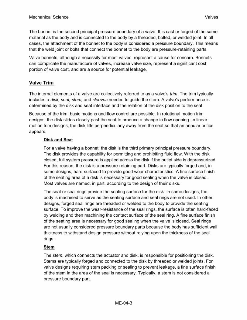
The bonnet is the second principal pressure boundary of a valve. It is cast or forged of the same
material as the body and is connected to the body by a threaded, bolted, or welded joint. In all
cases, the attachment of the bonnet to the body is considered a pressure boundary. This means
that the weld joint or bolts that connect the bonnet to the body are pressure-retaining parts.
Valve bonnets, although a necessity for most valves, represent a cause for concern. Bonnets
can complicate the manufacture of valves, increase valve size, represent a significant cost
portion of valve cost, and are a source for potential leakage.
Valve Trim
The internal elements of a valve are collectively referred to as a valve's trim. The trim typically
includes a disk, seat, stem, and sleeves needed to guide the stem. A valve's performance is
determined by the disk and seat interface and the relation of the disk position to the seat.
Because of the trim, basic motions and flow control are possible. In rotational motion trim
designs, the disk slides closely past the seat to produce a change in flow opening. In linear
motion trim designs, the disk lifts perpendicularly away from the seat so that an annular orifice
appears.
Disk and Seat
For a valve having a bonnet, the disk is the third primary principal pressure boundary.
The disk provides the capability for permitting and prohibiting fluid flow. With the disk
closed, full system pressure is applied across the disk if the outlet side is depressurized.
For this reason, the disk is a pressure-retaining part. Disks are typically forged and, in
some designs, hard-surfaced to provide good wear characteristics. A fine surface finish
of the seating area of a disk is necessary for good sealing when the valve is closed.
Most valves are named, in part, according to the design of their disks.
The seat or seal rings provide the seating surface for the disk. In some designs, the
body is machined to serve as the seating surface and seal rings are not used. In other
designs, forged seal rings are threaded or welded to the body to provide the seating
surface. To improve the wear-resistance of the seal rings, the surface is often hard-faced
by welding and then machining the contact surface of the seal ring. A fine surface finish
of the seating area is necessary for good sealing when the valve is closed. Seal rings
are not usually considered pressure boundary parts because the body has sufficient wall
thickness to withstand design pressure without relying upon the thickness of the seal
rings.
Stem
The stem, which connects the actuator and disk, is responsible for positioning the disk.
Stems are typically forged and connected to the disk by threaded or welded joints. For
valve designs requiring stem packing or sealing to prevent leakage, a fine surface finish
of the stem in the area of the seal is necessary. Typically, a stem is not considered a
pressure boundary part.

Mechanical Science Valves
ME-04-4
Connection of the disk to the stem can allow some rocking or rotation to ease the
positioning of the disk on the seat. Alternately, the stem may be flexible enough to let the
disk position itself against the seat. However, constant fluttering or rotation of a flexible
or loosely connected disk can destroy the disk or its connection to the stem.
Two types of valve stems are rising stems and non-rising stems. Illustrated in Figures 2
and 3, these two types of stems are easily distinguished by observation. For a rising
stem valve, the stem will rise above the actuator as the valve is opened. This occurs
because the stem is threaded and mated with the bushing threads of a yoke that is an
integral part of, or is mounted to, the bonnet.
Figure 2 Rising Stems

Mechanical Science Valves
ME-04-5
Figure 3 Non-rising Stems
There is no upward stem movement from outside the valve for a non-rising stem design.
For the non-rising stem design, the valve disk is threaded internally and mates with the
stem threads.
Valve Actuator
The actuator operates the stem and disk assembly. An actuator may be a manually operated
handwheel, manual lever, motor operator, solenoid operator, pneumatic operator, or hydraulic
ram. In some designs, the actuator is supported by the bonnet. In other designs, a yoke
mounted to the bonnet supports the actuator.
Except for certain hydraulically controlled valves, actuators are outside of the pressure
boundary. Yokes, when used, are always outside of the pressure boundary.
Valve Packing
Most valves use some form of packing to prevent leakage from the space between the stem and
the bonnet. Packing is commonly a fibrous material (such as flax) or another compound (such
as teflon) that forms a seal between the internal parts of a valve and the outside where the stem
extends through the body.
Valve packing must be properly compressed to prevent fluid loss and damage to the valve's
stem. If a valve's packing is too loose, the valve will leak, which is a safety hazard. If the packing
is too tight, it will impair the movement and possibly damage the stem.
Mechanical Science Valves
ME-04-6
Introduction to the Types of Valves
Because of the diversity of the types of systems, fluids, and environments in which valves must
operate, a vast array of valve types have been developed. Examples of the common types are
the globe valve, gate valve, ball valve, plug valve, butterfly valve, diaphragm valve, check valve,
pinch valve, and safety valve. Each type of valve has been designed to meet specific needs.
Some valves are capable of throttling flow, other valve types can only stop flow, others work
well in corrosive systems, and others handle high pressure fluids. Each valve type has certain
inherent advantages and disadvantages. Understanding these differences and how they affect
the valve's application or operation is necessary for the successful operation of a facility.
Although all valves have the same basic components and function to control flow in some
fashion, the method of controlling the flow can vary dramatically. In general, there are four
methods of controlling flow through a valve.
1. Move a disc, or plug into or against an orifice (for example, globe or needle type
valve).
2. Slide a flat, cylindrical, or spherical surface across an orifice (for example, gate
and plug valves).
3. Rotate a disc or ellipse about a shaft extending across the diameter of an orifice
(for example, a butterfly or ball valve).
4. Move a flexible material into the flow passage (for example, diaphragm and pinch
valves).
Each method of controlling flow has characteristics that makes it the best choice for a given
application of function.

Mechanical Science Valves
ME-04-7
Summary
The following important information in this chapter is summarized below:
Valve Functions and Basic Parts Summary
There are four basic types of flow control elements employed in valve design.
1. Move a disc, or plug into or against an orifice (for example, globe or
needle type valve).
2. Slide a flat, cylindrical, or spherical surface across an orifice (for example,
gate and plug valves).
3. Rotate a disc or ellipse about a shaft extending across the diameter of an
orifice (for example, a butterfly or ball valve).
4. Move a flexible material into the flow passage (for example, diaphragm
and pinch valves).
Valve stem leakage is usually controlled by properly compressing the packing
around the valve stem.
There are seven basic parts common to most valves.

Mechanical Science Valves
ME-04-8
TYPES OF VALVES
Due to the various environments, system fluids, and system conditions in which
flow must be controlled, a large number of valve designs have been developed.
A basic understanding of the differences between the various types of valves,
and how these differences affect valve function, will help ensure the proper
application of each valve type during design and the proper use of each valve
type during operation.
EO 1.4 Given a drawing of a valve, IDENTIFY each of the following types of valves:
a. Globe g. Diaphragm
b. Gate h. Pinch
c. Plug i. Check
d. Ball j. Safety/relief
e. Needle k. Reducing
f. Butterfly
EO 1.5 DESCRIBE the application of the following types of valves:
a. Globe g. Diaphragm
b. Gate h. Pinch
c. Plug i. Check
d. Ball j. Safety/relief
e. Needle k. Reducing
f. Butterfly
Gate Valves
A gate valve is a linear motion valve used to start or stop fluid flow; however, it does not
regulate or throttle flow. The name gate is derived from the appearance of the disk in the flow
stream. Figure 4 illustrates a gate valve.
The disk of a gate valve is completely removed from the flow stream when the valve is fully
open. This characteristic offers virtually no resistance to flow when the valve is open. Hence,
there is little pressure drop across an open gate valve.
When the valve is fully closed, a disk-to-seal ring contact surface exists for 360°, and good
sealing is provided. With the proper mating of a disk to the seal ring, very little or no leakage
occurs across the disk when the gate valve is closed.

Mechanical Science Valves
ME-04-9
Figure 4 Gate Valve
Mechanical Science Valves
ME-04-10
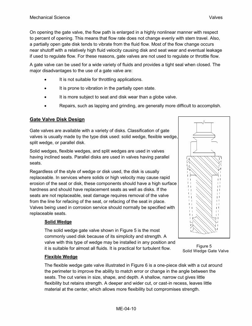
Figure 5 Solid Wedge Gate Valve
On opening the gate valve, the flow path is enlarged in a highly nonlinear manner with respect
to percent of opening. This means that flow rate does not change evenly with stem travel. Also,
a partially open gate disk tends to vibrate from the fluid flow. Most of the flow change occurs
near shutoff with a relatively high fluid velocity causing disk and seat wear and eventual leakage
if used to regulate flow. For these reasons, gate valves are not used to regulate or throttle flow.
A gate valve can be used for a wide variety of fluids and provides a tight seal when closed. The
major disadvantages to the use of a gate valve are:
It is not suitable for throttling applications.
It is prone to vibration in the partially open state.
It is more subject to seat and disk wear than a globe valve.
Repairs, such as lapping and grinding, are generally more difficult to accomplish.
Gate Valve Disk Design
Gate valves are available with a variety of disks. Classification of gate
valves is usually made by the type disk used: solid wedge, flexible wedge,
split wedge, or parallel disk.
Solid wedges, flexible wedges, and split wedges are used in valves
having inclined seats. Parallel disks are used in valves having parallel
seats.
Regardless of the style of wedge or disk used, the disk is usually
replaceable. In services where solids or high velocity may cause rapid
erosion of the seat or disk, these components should have a high surface
hardness and should have replacement seats as well as disks. If the
seats are not replaceable, seat damage requires removal of the valve
from the line for refacing of the seat, or refacing of the seat in place.
Valves being used in corrosion service should normally be specified with
replaceable seats.
Solid Wedge
The solid wedge gate valve shown in Figure 5 is the most
commonly used disk because of its simplicity and strength. A
valve with this type of wedge may be installed in any position and
it is suitable for almost all fluids. It is practical for turbulent flow.
Flexible Wedge
The flexible wedge gate valve illustrated in Figure 6 is a one-piece disk with a cut around
the perimeter to improve the ability to match error or change in the angle between the
seats. The cut varies in size, shape, and depth. A shallow, narrow cut gives little
flexibility but retains strength. A deeper and wider cut, or cast-in recess, leaves little
material at the center, which allows more flexibility but compromises strength.

Mechanical Science Valves
ME-04-11
A correct profile of the disk half in the flexible wedge design
can give uniform deflection properties at the disk edge, so
that the wedging force applied in seating will force the disk
seating surface uniformly and tightly against the seat.
Gate valves used in steam systems have flexible wedges.
The reason for using a flexible gate is to prevent binding of
the gate within the valve when the valve is in the closed
position. When steam lines are heated, they expand and
cause some distortion of valve bodies. If a solid gate fits
snugly between the seat of a valve in a cold steam system,
when the system is heated and pipes elongate, the seats
will compress against the gate and clamp the valve shut.
This problem is overcome by using a flexible gate, whose
design allows the gate to flex as the valve seat compresses
it.
The major problem associated with flexible gates is that
water tends to collect in the body neck. Under certain
conditions, the admission of steam may cause the valve
body neck to rupture, the bonnet to lift off, or the seat ring
to collapse. Following correct warming procedures prevent
these problems.
Split Wedge
Split wedge gate valves, as shown in Figure 7, are of
the ball and socket design. These are self-adjusting and
self-aligning to both seating surfaces. The disk is free to
adjust itself to the seating surface if one-half of the disk
is slightly out of alignment because of foreign matter
lodged between the disk half and the seat ring. This
type of wedge is suitable for handling non-condensing
gases and liquids at normal temperatures, particularly
corrosive liquids. Freedom of movement of the disk in
the carrier prevents binding even though the valve may
have been closed when hot and later contracted due to
cooling. This type of valve should be installed with the
stem in the vertical position.
Parallel Disk
The parallel disk gate valve illustrated in Figure 8 is
designed to prevent valve binding due to thermal
transients. This design is used in both low and high
pressure applications.
Figure 6 Flexible Wedge Gate Valve
Figure 7 Split Wedge Gate Valve

Mechanical Science Valves
ME-04-12
The wedge surfaces between the parallel face disk halves are caused to press together
under stem thrust and spread apart the disks to seal against the seats. The tapered
wedges may be part of the disk halves or they may be separate elements. The lower
wedge may bottom out on a rib at the valve bottom so that the stem can develop seating
force. In one version, the wedge contact surfaces are curved to keep the point of contact
close to the optimum.
Figure 8 Parallel Disk Gate Valve
In other parallel disk gates, the two halves do not move apart under wedge action.
Instead, the upstream pressure holds the downstream disk against the seat. A carrier
ring lifts the disks, and a spring or springs hold the disks apart and seated when there is
no upstream pressure.
Another parallel gate disk design provides for sealing only one port. In these designs,
the high pressure side pushes the disk open (relieving the disk) on the high pressure
side, but forces the disk closed on the low pressure side. With such designs, the amount
Mechanical Science Valves
ME-04-13
of seat leakage tends to decrease as differential pressure across the seat increases.
These valves will usually have a flow direction marking which will show which side is the
high pressure (relieving) side. Care should be taken to ensure that these valves are not
installed backwards in the system.
Some parallel disk gate valves used in high pressure systems are made with an integral
bonnet vent and bypass line. A three-way valve is used to position the line to bypass in
order to equalize pressure across the disks prior to opening. When the gate valve is
closed, the three-way valve is positioned to vent the bonnet to one side or the other. This
prevents moisture from accumulating in the bonnet. The three-way valve is positioned to
the high pressure side of the gate valve when closed to ensure that flow does not
bypass the isolation valve. The high pressure acts against spring compression and
forces one gate off of its seat. The three-way valve vents this flow back to the pressure
source.
Gate Valve Stem Design
Gate valves are classified as either rising stem or non-rising stem valves. For the non-rising
stem gate valve, the stem is threaded on the lower end into the gate. As the hand wheel on the
stem is rotated, the gate travels up or down the stem on the threads while the stem remains
vertically stationary. This type valve will almost always have a pointer-type indicator threaded
onto the upper end of the stem to indicate valve position. Figures 2 and 3 illustrate rising-stem
gate valves and non-rising stem gate valves.
The non-rising stem configuration places the stem threads within the boundary established by
the valve packing out of contact with the environment. This configuration assures that the stem
merely rotates in the packing without much danger of carrying dirt into the packing from outside
to inside.
Rising stem gate valves are designed so that the stem is raised out of the flowpath when the
valve is open. Rising stem gate valves come in two basic designs. Some have a stem that rises
through the handwheel while others have a stem that is threaded to the bonnet.
Gate Valve Seat Design
Seats for gate valves are either provided integral with the valve body or in a seat ring type of
construction. Seat ring construction provides seats which are either threaded into position or are
pressed into position and seal welded to the valve body. The latter form of construction is
recommended for higher temperature service.
Integral seats provide a seat of the same material of construction as the valve body while the
pressed-in or threaded-in seats permit variation. Rings with hard facings may be supplied for the
application where they are required.
Small, forged steel, gate valves may have hard faced seats pressed into the body. In some
series, this type of valve in sizes from 1/2 to 2 inches is rated for 2500 psig steam service. In
large gate valves, disks are often of the solid wedge type with seat rings threaded in, welded in,
Mechanical Science Valves
ME-04-14
or pressed in. Screwed in seat rings are
considered replaceable since they may be
removed and new seat rings installed.
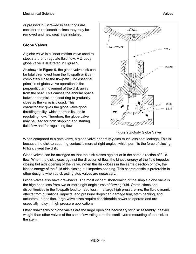
Globe Valves
A globe valve is a linear motion valve used to
stop, start, and regulate fluid flow. A Z-body
globe valve is illustrated in Figure 9.
As shown in Figure 9, the globe valve disk can
be totally removed from the flowpath or it can
completely close the flowpath. The essential
principle of globe valve operation is the
perpendicular movement of the disk away
from the seat. This causes the annular space
between the disk and seat ring to gradually
close as the valve is closed. This
characteristic gives the globe valve good
throttling ability, which permits its use in
regulating flow. Therefore, the globe valve
may be used for both stopping and starting
fluid flow and for regulating flow.
Figure 9 Z-Body Globe Valve
When compared to a gate valve, a globe valve generally yields much less seat leakage. This is
because the disk-to-seat ring contact is more at right angles, which permits the force of closing
to tightly seat the disk.
Globe valves can be arranged so that the disk closes against or in the same direction of fluid
flow. When the disk closes against the direction of flow, the kinetic energy of the fluid impedes
closing but aids opening of the valve. When the disk closes in the same direction of flow, the
kinetic energy of the fluid aids closing but impedes opening. This characteristic is preferable to
other designs when quick-acting stop valves are necessary.
Globe valves also have drawbacks. The most evident shortcoming of the simple globe valve is
the high head loss from two or more right angle turns of flowing fluid. Obstructions and
discontinuities in the flowpath lead to head loss. In a large high pressure line, the fluid dynamic
effects from pulsations, impacts, and pressure drops can damage trim, stem packing, and
actuators. In addition, large valve sizes require considerable power to operate and are
especially noisy in high pressure applications.
Other drawbacks of globe valves are the large openings necessary for disk assembly, heavier
weight than other valves of the same flow rating, and the cantilevered mounting of the disk to
the stem.
Mechanical Science Valves
ME-04-15
Globe Valve Body Designs
The three primary body designs for globe valves are Z-body, Y-body, and Angle.
Z-Body Design
The simplest design and most common for water applications is the Z-body. The Z-body
is illustrated in Figure 9. For this body design, the Z-shaped diaphragm or partition
across the globular body contains the seat. The horizontal setting of the seat allows the
stem and disk to travel at right angles to the pipe axis. The stem passes through the
bonnet which is attached to a large opening at the top of the valve body. This provides a
symmetrical form that simplifies manufacture, installation, and repair.
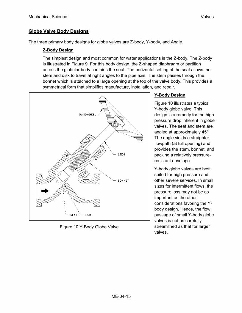
Y-Body Design
Figure 10 illustrates a typical
Y-body globe valve. This
design is a remedy for the high
pressure drop inherent in globe
valves. The seat and stem are
angled at approximately 45°.
The angle yields a straighter
flowpath (at full opening) and
provides the stem, bonnet, and
packing a relatively pressure-
resistant envelope.
Y-body globe valves are best
suited for high pressure and
other severe services. In small
sizes for intermittent flows, the
pressure loss may not be as
important as the other
considerations favoring the Y-
body design. Hence, the flow
passage of small Y-body globe
valves is not as carefully
streamlined as that for larger
valves.
Figure 10 Y-Body Globe Valve
Mechanical Science Valves
ME-04-16
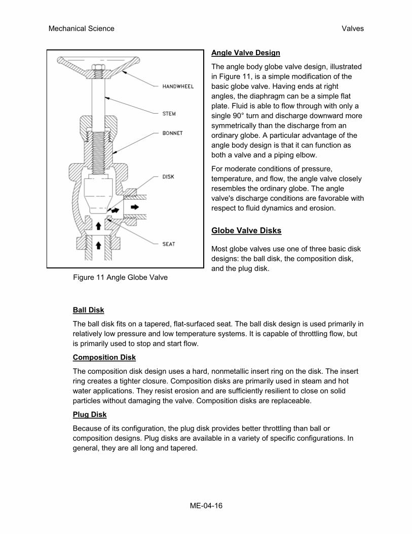
Angle Valve Design
The angle body globe valve design, illustrated
in Figure 11, is a simple modification of the
basic globe valve. Having ends at right
angles, the diaphragm can be a simple flat
plate. Fluid is able to flow through with only a
single 90° turn and discharge downward more
symmetrically than the discharge from an
ordinary globe. A particular advantage of the
angle body design is that it can function as
both a valve and a piping elbow.
For moderate conditions of pressure,
temperature, and flow, the angle valve closely
resembles the ordinary globe. The angle
valve's discharge conditions are favorable with
respect to fluid dynamics and erosion.
Globe Valve Disks
Most globe valves use one of three basic disk
designs: the ball disk, the composition disk,
and the plug disk.
Ball Disk
The ball disk fits on a tapered, flat-surfaced seat. The ball disk design is used primarily in
relatively low pressure and low temperature systems. It is capable of throttling flow, but
is primarily used to stop and start flow.
Composition Disk
The composition disk design uses a hard, nonmetallic insert ring on the disk. The insert
ring creates a tighter closure. Composition disks are primarily used in steam and hot
water applications. They resist erosion and are sufficiently resilient to close on solid
particles without damaging the valve. Composition disks are replaceable.
Plug Disk
Because of its configuration, the plug disk provides better throttling than ball or
composition designs. Plug disks are available in a variety of specific configurations. In
general, they are all long and tapered.
Figure 11 Angle Globe Valve
Mechanical Science Valves
ME-04-17
Globe Valve Disk and Stem Connections
Globe valves employ two methods for connecting disk and stem: T-slot construction and disk
nut construction. In the T-slot design, the disk slips over the stem. In the disk nut design, the
disk is screwed into the stem.
Globe Valve Seats
Globe valve seats are either integral with or screwed into the valve body. Many globe valves
have backseats. A backseat is a seating arrangement that provides a seal between the stem
and bonnet. When the valve is fully open, the disk seats against the backseat. The backseat
design prevents system pressure from building against the valve packing.
Globe Valve Direction of Flow
For low temperature applications, globe and angle valves are ordinarily installed so that
pressure is under the disk. This promotes easy operation, helps protect the packing, and
eliminates a certain amount of erosive action to the seat and disk faces. For high temperature
steam service, globe valves are installed so that pressure is above the disk. Otherwise, the
stem will contract upon cooling and tend to lift the disk off the seat.
Ball Valves
A ball valve is a rotational motion valve that uses a ball-shaped disk to stop or start fluid flow.
The ball, shown in Figure 12, performs the same function as the disk in the globe valve. When
the valve handle is turned to open the valve, the ball rotates to a point where the hole through
the ball is in line with the valve body inlet and outlet. When the valve is shut, the ball is rotated
so that the hole is perpendicular to the flow openings of the valve body and the flow is stopped.
Most ball valve actuators are of the quick-acting type, which require a 90° turn of the valve
handle to operate the valve. Other ball valve actuators are planetary gear-operated. This type of
gearing allows the use of a relatively small handwheel and operating force to operate a fairly
large valve.
Some ball valves have been developed with a spherical surface coated plug that is off to one
side in the open position and rotates into the flow passage until it blocks the flowpath
completely. Seating is accomplished by the eccentric movement of the plug. The valve requires
no lubrication and can be used for throttling service.

Mechanical Science Valves
ME-04-18
Figure 12 Typical Ball Valve
Advantages
A ball valve is generally the least expensive of any valve configuration and has low
maintenance costs. In addition to quick, quarter turn on-off operation, ball valves are
compact, require no lubrication, and give tight sealing with low torque.
Disadvantages
Conventional ball valves have relatively poor throttling characteristics. In a throttling
position, the partially exposed seat rapidly erodes because of the impingement of high
velocity flow.
Port Patterns
Ball valves are available in the venturi, reduced, and full port pattern. The full port
pattern has a ball with a bore equal to the inside diameter of the pipe.
Mechanical Science Valves
ME-04-19
Valve Materials
Balls are usually metallic in metallic bodies with trim (seats) produced from elastomeric
(elastic materials resembling rubber) materials. Plastic construction is also available.
The resilient seats for ball valves are made from various elastomeric material. The most
common seat materials are teflon (TFE), filled TFE, Nylon, Buna-N, Neoprene, and
combinations of these materials. Because of the elastomeric materials, these valves
cannot be used at elevated temperatures. Care must be used in the selection of the seat
material to ensure that it is compatible with the materials being handled by the valve.
Ball Valve Stem Design
The stem in a ball valve is not fastened to the ball. It normally has a rectangular portion at the
ball end which fits into a slot cut into the ball. The enlargement permits rotation of the ball as the
stem is turned.
Ball Valve Bonnet Design
A bonnet cap fastens to the body, which holds the stem assembly and ball in place. Adjustment
of the bonnet cap permits compression of the packing, which supplies the stem seal. Packing
for ball valve stems is usually in the configuration of die-formed packing rings normally of TFE,
TFE-filled, or TFE-impregnated material. Some ball valve stems are sealed by means of O-rings
rather than packing.
Ball Valve Position
Some ball valves are equipped with stops that permit only 90° rotation. Others do not have
stops and may be rotated 360°. With or without stops, a 90° rotation is all that is required for
closing or opening a ball valve.
The handle indicates valve ball position. When the handle lies along the axis of the valve, the
valve is open. When the handle lies 90° across the axis of the valve, the valve is closed. Some
ball valve stems have a groove cut in the top face of the stem that shows the flowpath through
the ball. Observation of the groove position indicates the position of the port through the ball.
This feature is particularly advantageous on multiport ball valves.
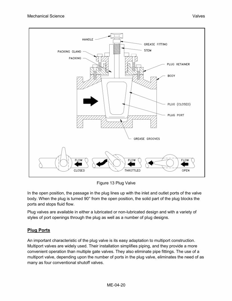
Plug Valves
A plug valve is a rotational motion valve used to stop or start fluid flow. The name is derived
from the shape of the disk, which resembles a plug. A plug valve is shown in Figure 13. The
simplest form of a plug valve is the petcock. The body of a plug valve is machined to receive the
tapered or cylindrical plug. The disk is a solid plug with a bored passage at a right angle to the
longitudinal axis of the plug.
Mechanical Science Valves
ME-04-20
Figure 13 Plug Valve
In the open position, the passage in the plug lines up with the inlet and outlet ports of the valve
body. When the plug is turned 90° from the open position, the solid part of the plug blocks the
ports and stops fluid flow.
Plug valves are available in either a lubricated or non-lubricated design and with a variety of
styles of port openings through the plug as well as a number of plug designs.
Plug Ports
An important characteristic of the plug valve is its easy adaptation to multiport construction.
Multiport valves are widely used. Their installation simplifies piping, and they provide a more
convenient operation than multiple gate valves. They also eliminate pipe fittings. The use of a
multiport valve, depending upon the number of ports in the plug valve, eliminates the need of as
many as four conventional shutoff valves.
Mechanical Science Valves
ME-04-21
Plug valves are normally used in non-throttling, on-off operations, particularly where frequent
operation of the valve is necessary. These valves are not normally recommended for throttling
service because, like the gate valve, a high percentage of flow change occurs near shutoff at
high velocity. However, a diamond-shaped port has been developed for throttling service.
Multiport Plug Valves
Multiport valves are particularly advantageous on transfer lines and for diverting services. A
single multiport valve may be installed in lieu of three or four gate valves or other types of
shutoff valve. A disadvantage is that many multiport valve configurations do not completely shut
off flow.
In most cases, one flowpath is always open. These valves are intended to divert the flow of one
line while shutting off flow from the other lines. If complete shutoff of flow is a requirement, it is
necessary that a style of multiport valve be used that permits this, or a secondary valve should
be installed on the main line ahead of the multiport valve to permit complete shutoff of flow.
In some multiport configurations, simultaneous flow to more than one port is also possible.
Great care should be taken in specifying the particular port arrangement required to guarantee
that proper operation will be possible.
Plug Valve Disks
Plugs are either round or cylindrical with a taper. They may have various types of port openings,
each with a varying degree of area relative to the corresponding inside diameter of the pipe.
Rectangular Port Plug
The most common port shape is the rectangular port. The rectangular port represents at
least 70% of the corresponding pipe's cross-sectional area.
Round Port Plug
Round port plug is a term that describes a valve that has a round opening through the
plug. If the port is the same size or larger than the pipe's inside diameter, it is referred to
as a full port. If the opening is smaller than the pipe's inside diameter, the port is referred
to as a standard round port. Valves having standard round ports are used only where
restriction of flow is unimportant.
Diamond Port Plug
A diamond port plug has a diamond-shaped port through the plug. This design is for
throttling service. All diamond port valves are venturi restricted flow type.
Lubricated Plug Valve Design
Clearances and leakage prevention are the chief considerations in plug valves. Many plug
valves are of all metal construction. In these versions, the narrow gap around the plug can allow
Mechanical Science Valves
ME-04-22
leakage. If the gap is reduced by sinking the taper plug deeper into the body, actuation torque
climbs rapidly and galling can occur. To remedy this condition, a series of grooves around the
body and plug port openings is supplied with grease prior to actuation. Applying grease
lubricates the plug motion and seals the gap between plug and body. Grease injected into a
fitting at the top of the stem travels down through a check valve in the passageway, past the
plug top to the grooves on the plug, and down to a well below the plug. The lubricant must be
compatible with the temperature and nature of the fluid. All manufacturers of lubricated plug
valves have developed a series of lubricants that are compatible with a wide range of media.
Their recommendation should be followed as to which lubricant is best suited for the service.
The most common fluids controlled by plug valves are gases and liquid hydrocarbons. Some
water lines have these valves, provided that lubricant contamination is not a serious danger.
Lubricated plug valves may be as large as 24 inches and have pressure capabilities up to 6000
psig. Steel or iron bodies are available. The plug can be cylindrical or tapered.
Non-lubricated Plugs
There are two basic types of non-lubricated plug valves: lift-type and elastomer sleeve or plug
coated. Lift-type valves provide a means of mechanically lifting the tapered plug slightly to
disengage it from the seating surface to permit easy rotation. The mechanical lifting can be
accomplished with a cam or external lever.
In a common, non-lubricated, plug valve having an elastomer sleeve, a sleeve of TFE
completely surrounds the plug. It is retained and locked in place by a metal body. This design
results in a primary seal being maintained between the sleeve and the plug at all times
regardless of position. The TFE sleeve is durable and inert to all but a few rarely encountered
chemicals. It also has a low coefficient of friction and is, therefore, self-lubricating.
Manually Operated Plug Valve Installation
When installing plug valves, care should be taken to allow room for the operation of the handle,
lever, or wrench. The manual operator is usually longer than the valve, and it rotates to a
position parallel to the pipe from a position 90° to the pipe.
Plug Valve Glands
The gland of the plug valve is equivalent to the bonnet of a gate or globe valve. The gland
secures the stem assembly to the valve body. There are three general types of glands: single
gland, screwed gland, and bolted gland.
To ensure a tight valve, the plug must be seated at all times. Gland adjustment should be kept
tight enough to prevent the plug from becoming unseated and exposing the seating surfaces to
the live fluid. Care should be exercised to not over-tighten the gland, which will result in a metal-
to-metal contact between the body and the plug. Such a metal-to-metal contact creates an
additional force which will require extreme effort to operate the valve.

Mechanical Science Valves
ME-04-23
Diaphragm Valves
A diaphragm valve is a linear motion valve that is used to start, regulate, and stop fluid flow. The
name is derived from its flexible disk, which mates with a seat located in the open area at the
top of the valve body to form a seal. A diaphragm valve is illustrated in Figure 14.
Figure 14 Straight Through Diaphragm Valve
Diaphragm valves are, in effect, simple "pinch clamp" valves. A resilient, flexible diaphragm is
connected to a compressor by a stud molded into the diaphragm. The compressor is moved up
and down by the valve stem. Hence, the diaphragm lifts when the compressor is raised. As the
compressor is lowered, the diaphragm is pressed against the contoured bottom in the straight
through valve illustrated in Figure 14 or the body weir in the weir-type valve illustrated in Figure
15.
Diaphragm valves can also be used for throttling service. The weir-type is the better throttling
valve but has a limited range. Its throttling characteristics are essentially those of a quick-
opening valve because of the large shutoff area along the seat.
A weir-type diaphragm valve is available to control small flows. It uses a two-piece compressor
component. Instead of the entire diaphragm lifting off the weir when the valve is opened, the first
increments of stem travel raise an inner compressor component that causes only the central
part of the diaphragm to lift. This creates a relatively small opening through the center of the
valve. After the inner compressor is completely open, the outer compressor component is raised
along with the inner compressor and the remainder of the throttling is similar to the throttling that
takes place in a conventional valve.
Diaphragm valves are particularly suited for the handling of corrosive fluids, fibrous slurries,
radioactive fluids, or other fluids that must remain free from contamination.
Diaphragm Construction
The operating mechanism of a diaphragm valve is not exposed to the media within the pipeline.
Sticky or viscous fluids cannot get into the bonnet to interfere with the operating mechanism.

Mechanical Science Valves
ME-04-24
Figure 15 Weir Diaphragm Valve
Mechanical Science Valves
ME-04-25
Many fluids that would clog, corrode, or gum up the working parts of most other types of valves
will pass through a diaphragm valve without causing problems. Conversely, lubricants used for
the operating mechanism cannot be allowed to contaminate the fluid being handled. There are
no packing glands to maintain and no possibility of stem leakage. There is a wide choice of
available diaphragm materials. Diaphragm life depends upon the nature of the material handled,
temperature, pressure, and frequency of operation.
Some elastomeric diaphragm materials may be unique in their excellent resistance to certain
chemicals at high temperatures. However, the mechanical properties of any elastomeric
material will be lowered at the higher temperature with possible destruction of the diaphragm at
high pressure. Consequently, the manufacturer should be consulted when they are used in
elevated temperature applications.
All elastomeric materials operate best below 150°F. Some will function at higher temperatures.
Viton, for example, is noted for its excellent chemical resistance and stability at high
temperatures. However, when fabricated into a diaphragm, Viton is subject to lowered tensile
strength just as any other elastomeric material would be at elevated temperatures. Fabric
bonding strength is also lowered at elevated temperatures, and in the case of Viton,
temperatures may be reached where the bond strength could become critical.
Fluid concentrations is also a consideration for diaphragm selection. Many of the diaphragm
materials exhibit satisfactory corrosion resistance to certain corrodents up to a specific
concentration and/or temperature. The elastomer may also have a maximum temperature
limitation based on mechanical properties which could be in excess of the allowable operating
temperature depending upon its corrosion resistance. This should be checked from a corrosion
table.
Diaphragm Valve Stem Assemblies
Diaphragm valves have stems that do not rotate. The valves are available with indicating and
non-indicating stems. The indicating stem valve is identical to the non-indicating stem valve
except that a longer stem is provided to extend up through the handwheel. For the non-
indicating stem design, the handwheel rotates a stem bushing that engages the stem threads
and moves the stem up and down. As the stem moves, so does the compressor that is pinned
to the stem. The diaphragm, in turn, is secured to the compressor.
Diaphragm Valve Bonnet Assemblies
Some diaphragm valves use a quick-opening bonnet and lever operator. This bonnet is
interchangeable with the standard bonnet on conventional weir-type bodies. A 90° turn of the
lever moves the diaphragm from full open to full closed. Diaphragm valves may also be
equipped with chain wheel operators, extended stems, bevel gear operators, air operators, and
hydraulic operators.
Many diaphragm valves are used in vacuum service. Standard bonnet construction can be
employed in vacuum service through 4 inches in size. On valves 4 inches and larger, a sealed,
Mechanical Science Valves
ME-04-26
evacuated, bonnet should be employed. This is recommended to guard against premature
diaphragm failure.
Sealed bonnets are supplied with a seal bushing on the non-indicating types and a seal bushing
plus O-ring on the indicating types. Construction of the bonnet assembly of a diaphragm valve is
illustrated in Figure 15. This design is recommended for valves that are handling dangerous
liquids and gases. In the event of a diaphragm failure, the hazardous materials will not be
released to the atmosphere. If the materials being handled are extremely hazardous, it is
recommended that a means be provided to permit a safe disposal of the corrodents from the
bonnet.
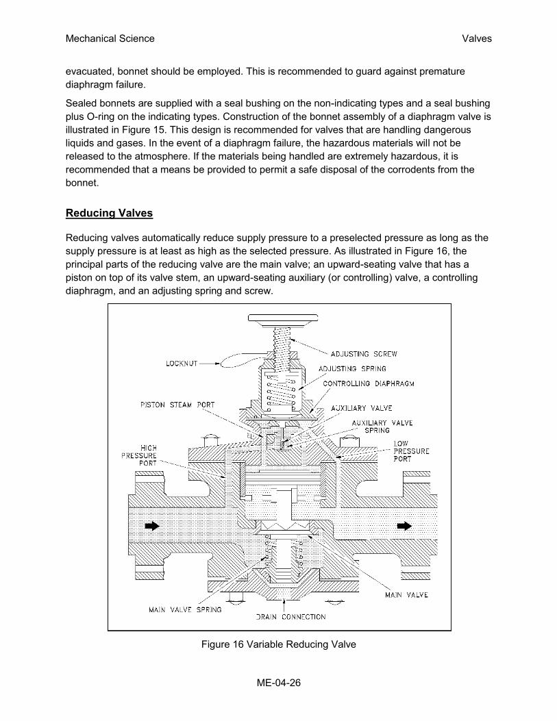
Reducing Valves
Reducing valves automatically reduce supply pressure to a preselected pressure as long as the
supply pressure is at least as high as the selected pressure. As illustrated in Figure 16, the
principal parts of the reducing valve are the main valve; an upward-seating valve that has a
piston on top of its valve stem, an upward-seating auxiliary (or controlling) valve, a controlling
diaphragm, and an adjusting spring and screw.
Figure 16 Variable Reducing Valve
Mechanical Science Valves
ME-04-27
Reducing valve operation is controlled by high pressure at the valve inlet and the adjusting
screw on top of the valve assembly. The pressure entering the main valve assists the main
valve spring in keeping the reducing valve closed by pushing upward on the main valve disk.
However, some of the high pressure is bled to an auxiliary valve on top of the main valve. The
auxiliary valve controls the admission of high pressure to the piston on top of the main valve.
The piston has a larger surface area than the main valve disk, resulting in a net downward force
to open the main valve. The auxiliary valve is controlled by a controlling diaphragm located
directly over the auxiliary valve.
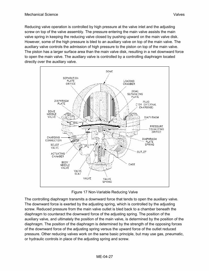
Figure 17 Non-Variable Reducing Valve
The controlling diaphragm transmits a downward force that tends to open the auxiliary valve.
The downward force is exerted by the adjusting spring, which is controlled by the adjusting
screw. Reduced pressure from the main valve outlet is bled back to a chamber beneath the
diaphragm to counteract the downward force of the adjusting spring. The position of the
auxiliary valve, and ultimately the position of the main valve, is determined by the position of the
diaphragm. The position of the diaphragm is determined by the strength of the opposing forces
of the downward force of the adjusting spring versus the upward force of the outlet reduced
pressure. Other reducing valves work on the same basic principle, but may use gas, pneumatic,
or hydraulic controls in place of the adjusting spring and screw.
Mechanical Science Valves
ME-04-28
Non-variable reducing valves, illustrated in Figure 17, replace the adjusting spring and screw
with a pre-pressurized dome over the diaphragm. The valve stem is connected either directly or
indirectly to the diaphragm. The valve spring below the diaphragm keeps the valve closed. As in
the variable valve, reduced pressure is bled through an orifice to beneath the diaphragm to
open the valve. Valve position is determined by the strength of the opposing forces of the
downward force of the pre-pressurized dome versus the upward force of the outlet-reduced
pressure.
Non-variable reducing valves eliminate the need for the intermediate auxiliary valve found in
variable reducing valves by having the opposing forces react directly on the diaphragm.
Therefore, non-variable reducing valves are more responsive to large pressure variations and
are less susceptible to failure than are variable reducing valves.
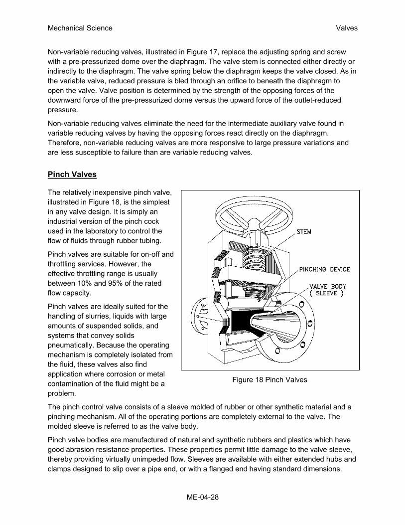
Pinch Valves
The relatively inexpensive pinch valve,
illustrated in Figure 18, is the simplest
in any valve design. It is simply an
industrial version of the pinch cock
used in the laboratory to control the
flow of fluids through rubber tubing.
Pinch valves are suitable for on-off and
throttling services. However, the
effective throttling range is usually
between 10% and 95% of the rated
flow capacity.
Pinch valves are ideally suited for the
handling of slurries, liquids with large
amounts of suspended solids, and
systems that convey solids
pneumatically. Because the operating
mechanism is completely isolated from
the fluid, these valves also find
application where corrosion or metal
contamination of the fluid might be a
problem.
The pinch control valve consists of a sleeve molded of rubber or other synthetic material and a
pinching mechanism. All of the operating portions are completely external to the valve. The
molded sleeve is referred to as the valve body.
Pinch valve bodies are manufactured of natural and synthetic rubbers and plastics which have
good abrasion resistance properties. These properties permit little damage to the valve sleeve,
thereby providing virtually unimpeded flow. Sleeves are available with either extended hubs and
clamps designed to slip over a pipe end, or with a flanged end having standard dimensions.
Figure 18 Pinch Valves

Mechanical Science Valves
ME-04-29
Pinch Valve Bodies
Pinch valves have molded bodies reinforced with fabric. Pinch valves generally have a
maximum operating temperature of 250oF. At 250oF, maximum operating pressure varies
generally from 100 psig for a 1-inch diameter valve and decreases to 15 psig for a 12-inch
diameter valve. Special pinch valves are available for temperature ranges of -100oF to 550oF
and operating pressures of 300 psig.
Most pinch valves are supplied with the sleeve (valve body) exposed. Another style fully
encloses the sleeve within a metallic body. This type controls flow either with the conventional
wheel and screw pinching device, hydraulically, or pneumatically with the pressure of the liquid
or gas within the metal case forcing the sleeve walls together to shut off flow.
Most exposed sleeve valves have limited vacuum application because of the tendency of the
sleeves to collapse when vacuum is applied. Some of the encased valves can be used on
vacuum service by applying a vacuum within the metal casing and thus preventing the collapse
of the sleeve.
Butterfly Valves
A butterfly valve, illustrated in
Figure 19, is a rotary motion valve
that is used to stop, regulate, and
start fluid flow. Butterfly valves are
easily and quickly operated
because a 90o rotation of the
handle moves the disk from a fully
closed to fully opened position.
Larger butterfly valves are
actuated by handwheels
connected to the stem through
gears that provide mechanical
advantage at the expense of
speed.
Butterfly valves possess many
advantages over gate, globe, plug,
and ball valves, especially for
large valve applications. Savings
in weight, space, and cost are the
most obvious advantages. The
maintenance costs are usually low
because there are a minimal
number of moving parts and there
are no pockets to trap fluids. Figure 19 Typical Butterfly Valve

Mechanical Science Valves
ME-04-30
Butterfly valves are especially well-suited for the handling of large flows of liquids or gases at
relatively low pressures and for the handling of slurries or liquids with large amounts of
suspended solids.
Butterfly valves are built on the principle of a pipe damper. The flow control element is a disk of
approximately the same diameter as the inside diameter of the adjoining pipe, which rotates on
either a vertical or horizontal axis. When the disk lies parallel to the piping run, the valve is fully
opened. When the disk approaches the perpendicular position, the valve is shut. Intermediate
positions, for throttling purposes, can be secured in place by handle-locking devices.
Butterfly Valve Seat Construction
Stoppage of flow is accomplished by the valve disk sealing against a seat that is on the inside
diameter periphery of the valve body. Many butterfly valves have an elastomeric seat against
which the disk seals. Other butterfly valves have a seal ring arrangement that uses a clamp-ring
and backing-ring on a serrated edged rubber ring. This design prevents extrusion of the O-rings.
In early designs, a metal disk was used to seal against a metal seat. This arrangement did not
provide a leak-tight closure, but did provide sufficient closure in some applications (i.e., water
distribution lines).
Butterfly Valve Body Construction
Butterfly valve body construction varies. The most economical is the wafer type that fits between
two pipeline flanges. Another type, the lug wafer design, is held in place between two pipe
flanges by bolts that join the two flanges and pass through holes in the valve's outer casing.
Butterfly valves are available with conventional flanged ends for bolting to pipe flanges, and in a
threaded end construction.
Butterfly Valve Disk and Stem Assemblies
The stem and disk for a butterfly valve are separate pieces. The disk is bored to receive the
stem. Two methods are used to secure the disk to the stem so that the disk rotates as the stem
is turned. In the first method, the disk is bored through and secured to the stem with bolts or
pins. The alternate method involves boring the disk as before, then shaping the upper stem bore
to fit a squared or hex-shaped stem. This method allows the disk to "float" and seek its center in
the seat. Uniform sealing is accomplished and external stem fasteners are eliminated. This
method of assembly is advantageous in the case of covered disks and in corrosive applications.
In order for the disk to be held in the proper position, the stem must extend beyond the bottom
of the disk and fit into a bushing in the bottom of the valve body. One or two similar bushings
are along the upper portion of the stem as well. These bushings must be either resistant to the
media being handled or sealed so that the corrosive media cannot come into contact with them.
Stem seals are accomplished either with packing in a conventional stuffing box or by means of
O-ring seals. Some valve manufacturers, particularly those specializing in the handling of

Mechanical Science Valves
ME-04-31
Figure 20 Needle Valve
corrosive materials, place a stem seal on the inside of the valve so that no material being
handled by the valve can come into contact with the valve stem. If a stuffing box or external O-
ring is employed, the fluid passing through the valve will come into contact with the valve stem.
Needle Valves
A needle valve, as shown in Figure 20, is used
to make relatively fine adjustments in the
amount of fluid flow.
The distinguishing characteristic of a needle
valve is the long, tapered, needle-like point on
the end of the valve stem. This "needle" acts as
a disk. The longer part of the needle is smaller
than the orifice in the valve seat and passes
through the orifice before the needle seats. This
arrangement permits a very gradual increase or
decrease in the size of the opening. Needle
valves are often used as component parts of
other, more complicated valves. For example,
they are used in some types of reducing valves.
Needle Valve Applications
Most constant pressure pump governors have
needle valves to minimize the effects of
fluctuations in pump discharge pressure.
Needle valves are also used in some
components of automatic combustion control
systems where very precise flow regulation is
necessary.
Needle Valve Body Designs
One type of body design for a needle valve is the bar stock body. Bar stock bodies are common,
and, in globe types, a ball swiveling in the stem provides the necessary rotation for seating
without damage. The bar stock body is illustrated in Figure 21.

Mechanical Science Valves
ME-04-32
Figure 21 Bar-Stock Instrument Valve
Needle valves are frequently used as metering valves. Metering valves are used for extremely
fine flow control. The thin disk or orifice allows for linear flow characteristics. Therefore, the
number of handwheel turns can be directly correlated to the amount of flow. A typical metering
valve has a stem with 40 threads per inch.
Needle valves generally use one of two styles of stem packing: an O-ring with TFE backing
rings or a TFE packing cylinder. Needle valves are often equipped with replaceable seats for
ease of maintenance.
Check Valves
Check valves are designed to prevent the reversal of flow in a piping system. These valves are
activated by the flowing material in the pipeline. The pressure of the fluid passing through the
system opens the valve, while any reversal of flow will close the valve. Closure is accomplished
by the weight of the check mechanism, by back pressure, by a spring, or by a combination of
these means. The general types of check valves are swing, tilting-disk, piston, butterfly, and
stop.
Swing Check Valves
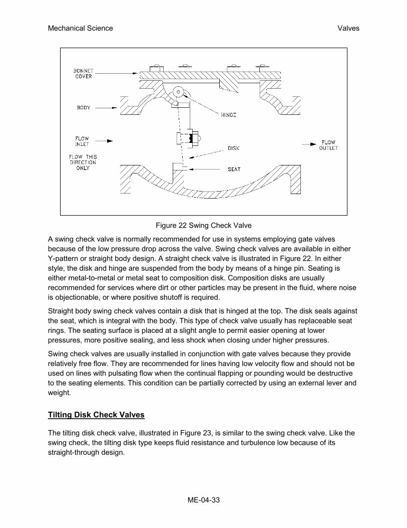
A swing check valve is illustrated in Figure 22. The valve allows full, unobstructed flow and
automatically closes as pressure decreases. These valves are fully closed when the flow
reaches zero and prevent back flow. Turbulence and pressure drop within the valve are very
low.
Mechanical Science Valves
ME-04-33
Figure 22 Swing Check Valve
A swing check valve is normally recommended for use in systems employing gate valves
because of the low pressure drop across the valve. Swing check valves are available in either
Y-pattern or straight body design. A straight check valve is illustrated in Figure 22. In either
style, the disk and hinge are suspended from the body by means of a hinge pin. Seating is
either metal-to-metal or metal seat to composition disk. Composition disks are usually
recommended for services where dirt or other particles may be present in the fluid, where noise
is objectionable, or where positive shutoff is required.
Straight body swing check valves contain a disk that is hinged at the top. The disk seals against
the seat, which is integral with the body. This type of check valve usually has replaceable seat
rings. The seating surface is placed at a slight angle to permit easier opening at lower
pressures, more positive sealing, and less shock when closing under higher pressures.
Swing check valves are usually installed in conjunction with gate valves because they provide
relatively free flow. They are recommended for lines having low velocity flow and should not be
used on lines with pulsating flow when the continual flapping or pounding would be destructive
to the seating elements. This condition can be partially corrected by using an external lever and
weight.
Tilting Disk Check Valves
The tilting disk check valve, illustrated in Figure 23, is similar to the swing check valve. Like the
swing check, the tilting disk type keeps fluid resistance and turbulence low because of its
straight-through design.
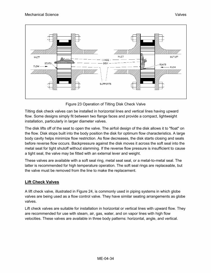
Mechanical Science Valves
ME-04-34
Figure 23 Operation of Tilting Disk Check Valve
Tilting disk check valves can be installed in horizontal lines and vertical lines having upward
flow. Some designs simply fit between two flange faces and provide a compact, lightweight
installation, particularly in larger diameter valves.
The disk lifts off of the seat to open the valve. The airfoil design of the disk allows it to "float" on
the flow. Disk stops built into the body position the disk for optimum flow characteristics. A large
body cavity helps minimize flow restriction. As flow decreases, the disk starts closing and seals
before reverse flow occurs. Backpressure against the disk moves it across the soft seal into the
metal seat for tight shutoff without slamming. If the reverse flow pressure is insufficient to cause
a tight seal, the valve may be fitted with an external lever and weight.
These valves are available with a soft seal ring, metal seat seal, or a metal-to-metal seal. The
latter is recommended for high temperature operation. The soft seal rings are replaceable, but
the valve must be removed from the line to make the replacement.
Lift Check Valves
A lift check valve, illustrated in Figure 24, is commonly used in piping systems in which globe
valves are being used as a flow control valve. They have similar seating arrangements as globe
valves.
Lift check valves are suitable for installation in horizontal or vertical lines with upward flow. They
are recommended for use with steam, air, gas, water, and on vapor lines with high flow
velocities. These valves are available in three body patterns: horizontal, angle, and vertical.

Mechanical Science Valves
ME-04-35
Figure 24 Lift Check Valve
Flow to lift check valves must always enter below the seat. As the flow enters, the disk or ball is
raised within guides from the seat by the pressure of the upward flow. When the flow stops or
reverses, the disk or ball is forced onto the seat of the valve by both the backflow and gravity.
Some types of lift check valves may be installed horizontally. In this design, the ball is
suspended by a system of guide ribs.
This type of check valve design is
generally employed in plastic check
valves.
The seats of metallic body lift check
valves are either integral with the body or
contain renewable seat rings. Disk
construction is similar to the disk
construction of globe valves with either
metal or composition disks. Metal disk
and seat valves can be reground using
the same techniques as is used for globe
valves.
Piston Check Valves
A piston check valve, illustrated in Figure
25, is essentially a lift check valve. It has
a dashpot consisting of a piston and Figure 25 Piston Check Valve
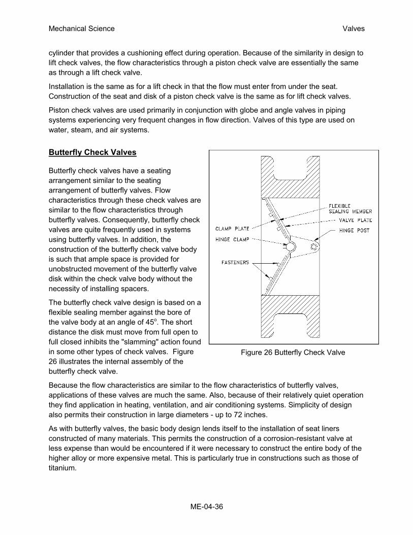
Mechanical Science Valves
ME-04-36
cylinder that provides a cushioning effect during operation. Because of the similarity in design to
lift check valves, the flow characteristics through a piston check valve are essentially the same
as through a lift check valve.
Installation is the same as for a lift check in that the flow must enter from under the seat.
Construction of the seat and disk of a piston check valve is the same as for lift check valves.
Piston check valves are used primarily in conjunction with globe and angle valves in piping
systems experiencing very frequent changes in flow direction. Valves of this type are used on
water, steam, and air systems.
Butterfly Check Valves
Butterfly check valves have a seating
arrangement similar to the seating
arrangement of butterfly valves. Flow
characteristics through these check valves are
similar to the flow characteristics through
butterfly valves. Consequently, butterfly check
valves are quite frequently used in systems
using butterfly valves. In addition, the
construction of the butterfly check valve body
is such that ample space is provided for
unobstructed movement of the butterfly valve
disk within the check valve body without the
necessity of installing spacers.
The butterfly check valve design is based on a
flexible sealing member against the bore of
the valve body at an angle of 45o. The short
distance the disk must move from full open to
full closed inhibits the "slamming" action found
in some other types of check valves. Figure
26 illustrates the internal assembly of the
butterfly check valve.
Because the flow characteristics are similar to the flow characteristics of butterfly valves,
applications of these valves are much the same. Also, because of their relatively quiet operation
they find application in heating, ventilation, and air conditioning systems. Simplicity of design
also permits their construction in large diameters - up to 72 inches.
As with butterfly valves, the basic body design lends itself to the installation of seat liners
constructed of many materials. This permits the construction of a corrosion-resistant valve at
less expense than would be encountered if it were necessary to construct the entire body of the
higher alloy or more expensive metal. This is particularly true in constructions such as those of
titanium.
Figure 26 Butterfly Check Valve

Mechanical Science Valves
ME-04-37
Flexible sealing members are available in Buna-N, Neoprene, Nordel, Hypalon, Viton, Tyon,
Urethane, Butyl, Silicone, and TFE as standard, with other materials available on special order.
The valve body essentially is a length of pipe that is fitted with flanges or has threaded, grooved,
or plain ends. The interior is bored to a fine finish. The flanged end units can have liners of
various metals or plastics installed depending upon the service requirements. Internals and
fasteners are always of the same material as the liner.
Butterfly check valves may be installed
horizontally or vertically with the vertical
flow either upward or downward. Care
should be taken to ensure that the valve
is installed so that the entering flow
comes from the hinge post end of the
valve; otherwise, all flow will be stopped.
Stop Check Valves
A stop check valve, illustrated in Figure
27, is a combination of a lift check valve
and a globe valve. It has a stem which,
when closed, prevents the disk from
coming off the seat and provides a tight
seal (similar to a globe valve). When the
stem is operated to the open position,
the valve operates as a lift check. The
stem is not connected to the disk and
functions to close the valve tightly or to
limit the travel of the valve disk in the
open direction.
Relief and Safety Valves
Relief and safety valves prevent equipment damage by relieving accidental over-pressurization
of fluid systems. The main difference between a relief valve and a safety valve is the extent of
opening at the setpoint pressure.
A relief valve, illustrated in Figure 28, gradually opens as the inlet pressure increases above the
setpoint. A relief valve opens only as necessary to relieve the over-pressure condition. A safety
valve, illustrated in Figure 29, rapidly pops fully open as soon as the pressure setting is
reached. A safety valve will stay fully open until the pressure drops below a reset pressure. The
reset pressure is lower than the actuating pressure setpoint. The difference between the
actuating pressure setpoint and the pressure at which the safety valve resets is called
blowdown. Blowdown is expressed as a percentage of the actuating pressure setpoint.
Figure 27 Stop Check Valve
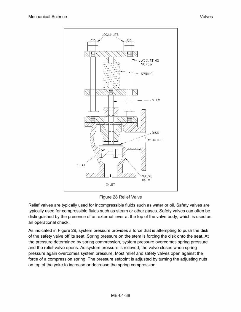
Mechanical Science Valves
ME-04-38
Figure 28 Relief Valve
Relief valves are typically used for incompressible fluids such as water or oil. Safety valves are
typically used for compressible fluids such as steam or other gases. Safety valves can often be
distinguished by the presence of an external lever at the top of the valve body, which is used as
an operational check.
As indicated in Figure 29, system pressure provides a force that is attempting to push the disk
of the safety valve off its seat. Spring pressure on the stem is forcing the disk onto the seat. At
the pressure determined by spring compression, system pressure overcomes spring pressure
and the relief valve opens. As system pressure is relieved, the valve closes when spring
pressure again overcomes system pressure. Most relief and safety valves open against the
force of a compression spring. The pressure setpoint is adjusted by turning the adjusting nuts
on top of the yoke to increase or decrease the spring compression.
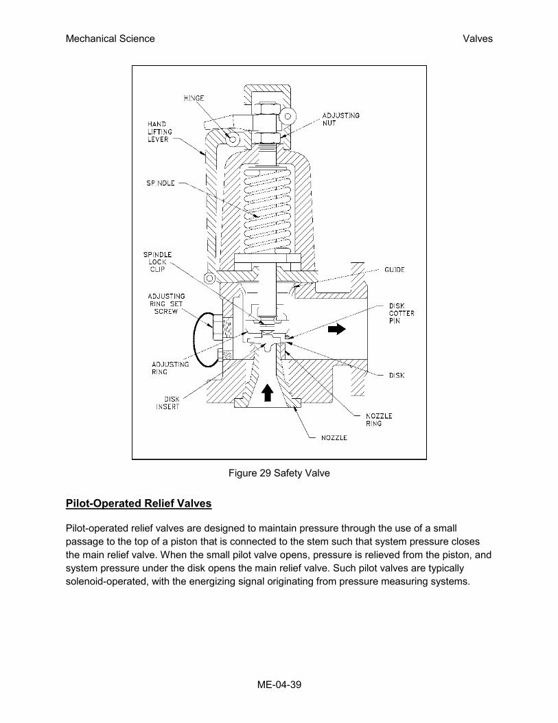
Mechanical Science Valves
ME-04-39
Figure 29 Safety Valve
Pilot-Operated Relief Valves
Pilot-operated relief valves are designed to maintain pressure through the use of a small
passage to the top of a piston that is connected to the stem such that system pressure closes
the main relief valve. When the small pilot valve opens, pressure is relieved from the piston, and
system pressure under the disk opens the main relief valve. Such pilot valves are typically
solenoid-operated, with the energizing signal originating from pressure measuring systems.

Mechanical Science Valves
ME-04-40
Summary
The following important information in this chapter is summarized below.
Types of Valves Summary
Gate valves are generally used in systems where low flow resistance for
a fully open valve is desired and there is no need to throttle the flow.
Globe valves are used in systems where good throttling characteristics
and low seat leakage are desired and a relatively high head loss in an
open valve is acceptable.
Ball valves allow quick, quarter turn on-off operation and have poor
throttling characteristics.
Plug valves are often used to direct flow between several different ports
through use of a single valve.
Diaphragm valves and pinch valves are used in systems where it is
desirable for the entire operating mechanism to be completely isolated
from the fluid.
Butterfly valves provide significant advantages over other valve designs
in weight, space, and cost for large valve applications.
Check valves automatically open to allow flow in one direction and seat to
prevent flow in the reverse direction.
A stop check valve is a combination of a lift check valve and a globe
valve and incorporates the characteristics of both.
Safety/relief valves are used to provide automatic overpressurization
protection for a system.

Mechanical Science Valves
ME-04-41
VALVE ACTUATORS
Some type of actuator is necessary to allow for the positioning of a valve.
Actuators vary from simple manual handwheels to relatively complex electrical
and hydraulic manipulators.
EO 1.6 DESCRIBE the construction and principle of operation for the following types
of valve actuators:
a. Manual
b. Electric motor
c. Pneumatic
d. Hydraulic
e. Solenoid
Introduction
Valve actuators are selected based upon a number of factors including torque necessary to
operate the valve and the need for automatic actuation. Types of actuators include manual
handwheel, manual lever, electrical motor, pneumatic, solenoid, hydraulic piston, and self-
actuated. All actuators except manual handwheel and lever are adaptable to automatic
actuation.
Manual, Fixed, and Hammer
Actuators
Manual actuators are capable of
placing the valve in any position but
do not permit automatic operation.
The most common type mechanical
actuator is the handwheel. This type
includes handwheels fixed to the
stem, hammer handwheels, and
handwheels connected to the stem
through gears.
Handwheels Fixed to Stem
As illustrated in Figure 30, handwheels fixed to the stem provide only the mechanical advantage
of the wheel. When these valves are exposed to high operating temperatures, valve binding
makes operation difficult.
Figure 30 Fixed Handwheel

Mechanical Science Valves
ME-04-42
Hammer Handwheel
As illustrated in Figure 31, the
hammer handwheel moves freely
through a portion of its turn and
then hits against a lug on a
secondary wheel. The secondary
wheel is attached to the valve
stem. With this arrangement, the
valve can be pounded shut for
tight closure or pounded open if it
is stuck shut.
Figure 31 Hammer Handwheel
Gears
If additional mechanical advantage is
necessary for a manually-operated
valve, the valve bonnet is fitted with
manually-operated gear heads as
illustrated in Figure 32. A special
wrench or handwheel attached to the
pinion shaft permits one individual to
operate the valve when two individuals
might be needed without the gear
advantage. Because several turns of
the pinion are necessary to produce
one turn of the valve stem, the
operating time of large valves is
exceptionally long. The use of portable
air motors connected to the pinion
shaft decreases the valve operating
time.
Figure 32 Manual Gear Head

Mechanical Science Valves
ME-04-43
Electric Motor Actuators
Electric motors permit manual, semi-automatic, and automatic operation of the valve. Motors
are used mostly for open-close functions, although they are adaptable to positioning the valve to
any point opening as illustrated in Figure 33. The motor is usually a, reversible, high speed type
connected through a gear train to reduce the motor speed and thereby increase the torque at
the stem. Direction of motor rotation determines direction of disk motion. The electrical actuation
can be semi-automatic, as when the motor is started by a control system. A handwheel, which
can be engaged to the gear train, provides for manual operating of the valve. Limit switches are
normally provided to stop the motor automatically at full open and full closed valve positions.
Limit switches are operated either physically by position of the valve or torsionally by torque of
the motor.
Figure 33 Electric Motor Actuator
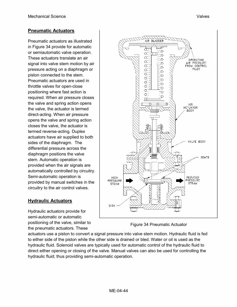
Mechanical Science Valves
ME-04-44
Pneumatic Actuators
Pneumatic actuators as illustrated
in Figure 34 provide for automatic
or semiautomatic valve operation.
These actuators translate an air
signal into valve stem motion by air
pressure acting on a diaphragm or
piston connected to the stem.
Pneumatic actuators are used in
throttle valves for open-close
positioning where fast action is
required. When air pressure closes
the valve and spring action opens
the valve, the actuator is termed
direct-acting. When air pressure
opens the valve and spring action
closes the valve, the actuator is
termed reverse-acting. Duplex
actuators have air supplied to both
sides of the diaphragm. The
differential pressure across the
diaphragm positions the valve
stem. Automatic operation is
provided when the air signals are
automatically controlled by circuitry.
Semi-automatic operation is
provided by manual switches in the
circuitry to the air control valves.
Hydraulic Actuators
Hydraulic actuators provide for
semi-automatic or automatic
positioning of the valve, similar to
the pneumatic actuators. These
actuators use a piston to convert a signal pressure into valve stem motion. Hydraulic fluid is fed
to either side of the piston while the other side is drained or bled. Water or oil is used as the
hydraulic fluid. Solenoid valves are typically used for automatic control of the hydraulic fluid to
direct either opening or closing of the valve. Manual valves can also be used for controlling the
hydraulic fluid; thus providing semi-automatic operation.
Figure 34 Pneumatic Actuator
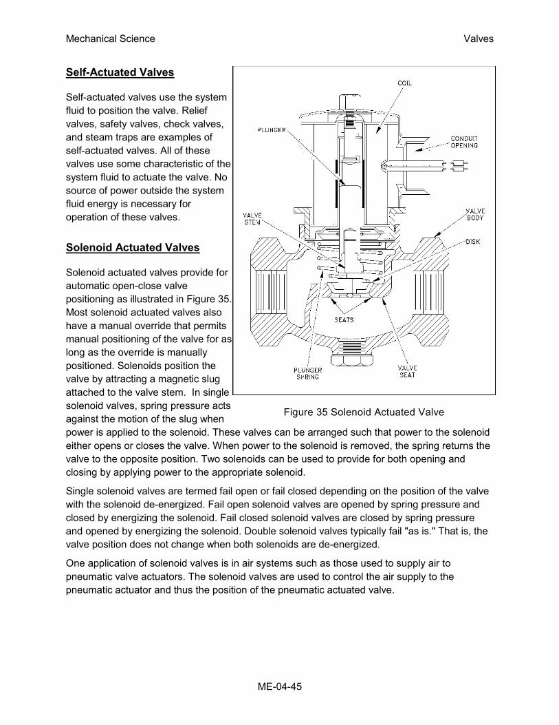
Mechanical Science Valves
ME-04-45
Figure 35 Solenoid Actuated Valve
Self-Actuated Valves
Self-actuated valves use the system
fluid to position the valve. Relief
valves, safety valves, check valves,
and steam traps are examples of
self-actuated valves. All of these
valves use some characteristic of the
system fluid to actuate the valve. No
source of power outside the system
fluid energy is necessary for
operation of these valves.
Solenoid Actuated Valves
Solenoid actuated valves provide for
automatic open-close valve
positioning as illustrated in Figure 35.
Most solenoid actuated valves also
have a manual override that permits
manual positioning of the valve for as
long as the override is manually
positioned. Solenoids position the
valve by attracting a magnetic slug
attached to the valve stem. In single
solenoid valves, spring pressure acts
against the motion of the slug when
power is applied to the solenoid. These valves can be arranged such that power to the solenoid
either opens or closes the valve. When power to the solenoid is removed, the spring returns the
valve to the opposite position. Two solenoids can be used to provide for both opening and
closing by applying power to the appropriate solenoid.
Single solenoid valves are termed fail open or fail closed depending on the position of the valve
with the solenoid de-energized. Fail open solenoid valves are opened by spring pressure and
closed by energizing the solenoid. Fail closed solenoid valves are closed by spring pressure
and opened by energizing the solenoid. Double solenoid valves typically fail "as is." That is, the
valve position does not change when both solenoids are de-energized.
One application of solenoid valves is in air systems such as those used to supply air to
pneumatic valve actuators. The solenoid valves are used to control the air supply to the
pneumatic actuator and thus the position of the pneumatic actuated valve.

Mechanical Science Valves
ME-04-46
Speed of Power Actuators
Plant safety considerations dictate valve speeds for certain safety-related valves. Where a
system must be very quickly isolated or opened, very fast valve actuation is required. Where the
opening of a valve results in injection of relatively cold water to a hot system, slower opening is
necessary to minimize thermal shock. Engineering design selects the actuator for safety-related
valves based upon speed and power requirements and availability of energy to the actuator.
In general, fastest actuation is provided by hydraulic, pneumatic, and solenoid actuators.
However, solenoids are not practical for large valves because their size and power
requirements would be excessive. Also, hydraulic and pneumatic actuators require a system for
providing hydraulic or pneumatic energy. The speed of actuation in either case can be set by
installing appropriately sized orifices in the hydraulic or pneumatic lines. In certain cases, the
valve is closed by spring pressure, which is opposed by hydraulic or pneumatic pressure to
keep the valve open.
Electrical motors provide relatively fast actuation. Actual valve speed is set by the combination
of motor speed and gear ratio. This combination can be selected to provide full valve travel
within a range from about two seconds to several seconds.
Valve Position Indication
Operators require indication of the position of certain valves to permit knowledgeable operation
of the plant. For such valves, remote valve position indication is provided in the form of position
lights that indicate if valves are open or closed. Remote valve position indication circuits use a
position detector that senses stem and disk position or actuator position. One type of position
detector is the mechanical limit switch, which is physically operated by valve movement.
Another type is magnetic switches or transformers that sense movement of their magnetic
cores, which are physically operated by valve movement.
Local valve position indication refers to some visually discernible characteristic of the valve that
indicates valve position. Rising stem valve position is indicated by the stem position. Non-rising
stem valves sometimes have small mechanical pointers that are operated by the valve actuator
simultaneously with valve operation. Power actuated valves typically have a mechanical pointer
that provides local valve position indication. On the other hand, some valves do not have any
feature for position indication.
Mechanical Science Valves
ME-04-47
Summary
The important information in this chapter is summarized below.
Valve Actuators Summary
Manual actuators are the most common type of valve actuators. Manual
actuators include handwheels attached to the valve stem directly and
handwheels attached through gears to provide a mechanical advantage.
Electric motor actuators consist of reversible electric motors connected to
the valve stem through a gear train that reduces rotational speed and
increases torque.
Pneumatic actuators use air pressure on either one or both sides of a
diaphragm to provide the force to position the valve.
Hydraulic actuators use a pressurized liquid on one or both sides of a
piston to provide the force required to position the valve.
Solenoid actuators have a magnetic slug attached to the valve stem. The
force to position the valve comes from the magnetic attraction between the
slug on the valve stem and the coil of the electromagnet in the valve
actuator.