Embed Size (px)
DESCRIPTION
the detail literature of valves is being mentioned in the document.
Citation preview
VALVES
1. INTRODUCTION:-
The conduits in all water power plants except large low head plants are ordinarily provided with shut off devices. Generally these components are valves. They exist in different types & design depending on function & requirements.
In any power plant valves for different purposes are usually needed. Normally it is a shut-off valve just in front of the turbine. In this way the turbine may be emptied the shaft or penstock. In addition the guide vane cascade is depressuruised so that leakage flow is avoided.
With a long head race tunnel & surge chamber it is normal to have a shut off valve just downstream of the surge chamber. In this way the shaft or penstock may be emptied without emptying the tunnel.
To prevent large damage at an eventual rupture of the penstock, a pipe break valve is normally installed in the pipe just downstream of the shut off valve. This valve closes automatically when the water velocity exceeds a certain set value.
The most relevant types of valves are:
1.Spherical Valves. 2.Butterfly Valves. 3.Gate Valves. 4. Ring Valves.
1.1 SPHERICAL VALVES:-
Spherical valves are applied mostly as shut off valves in front of high head water turbines. They are however, used as pipe brake valves as well. Spherical valves are presently covering a pressure range of 160m to 1250m water head.
The spherical valves consist of the valve housing with flanges, valve rotor, bearings & seals.
1.1.1 VALVE HOUSING & VALVE ROTOR:-
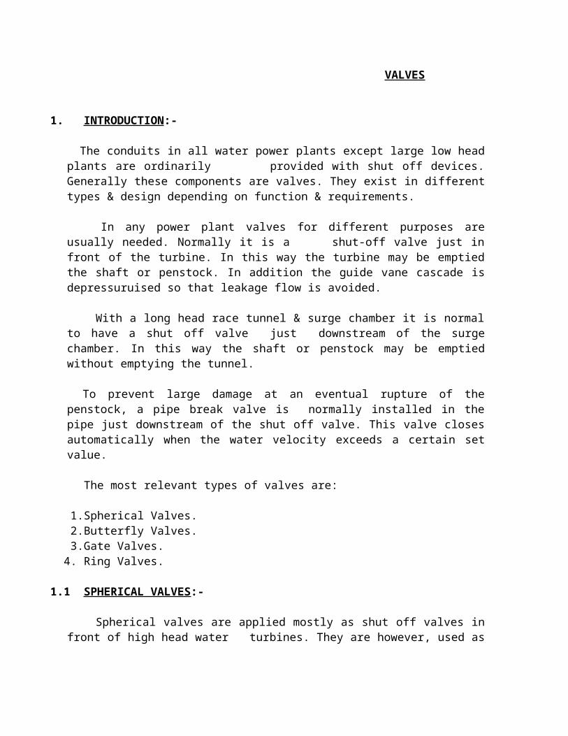
The valve housing has a spherical shape. It may either be axially split permanently in two halves & bolted together with heavy flanges, or these two halves may be welded together after the rotor has been installed.
The rotor inside the valve housing is principally shaped spherically as well. The circular passage through the rotor is equal to the size of the valve inlet & outlet.
The length of the passage is dimensioned to fit almost close to the inner end faces at inlet & outlet of the valve housing. In this way the flow losses through the valve become about the same as in a corresponding pipe length.
Fig.1:- Pictorial view of new spherical valve.
1.1.2 VALVE ROTOR TRUUNIONS AND BEARINGS:-
The truunions on the valve rotor are horizontally supported in the valve housing. The rotor is turning on these truunions by an angle 90º from open to closed position. The valve is normally designed to close under the worst possible conditions. This worst case is to close a valve upstream of the turbine when the guide vane cascade of the turbine is fully open.
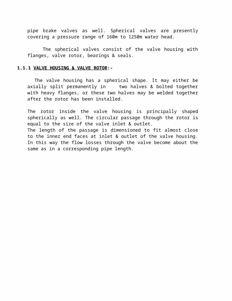
The bearings are designed with bushings made of lead-bronze. The bushing is pressed into a bearing housing & provided with two sealings. The inner seal is an O-ring primarily for keeping the bearing free from sand & mud. If this seal after some time is not leak tight, the outer seal is a reserve. This seal is of U-seal type.
Lubrication grease to the bearings is pressed through several borings into a section of grooves in the bearing surface.
Fig.2:- Aerial View of pictorial body.
1.1.3 SEALS FOR CLOSED VALVE:-
Spherical valves usually have a main seal downstream & an auxiliary seal upstream of the passage of the rotor. The valve rotor is provided with two seal rings, one downstream & one upstream. These are made of stainless steel & fixed with screws to the rotor.
In closed position the circular passage of the rotor is turned 90º from the open position & the seals are then activated.
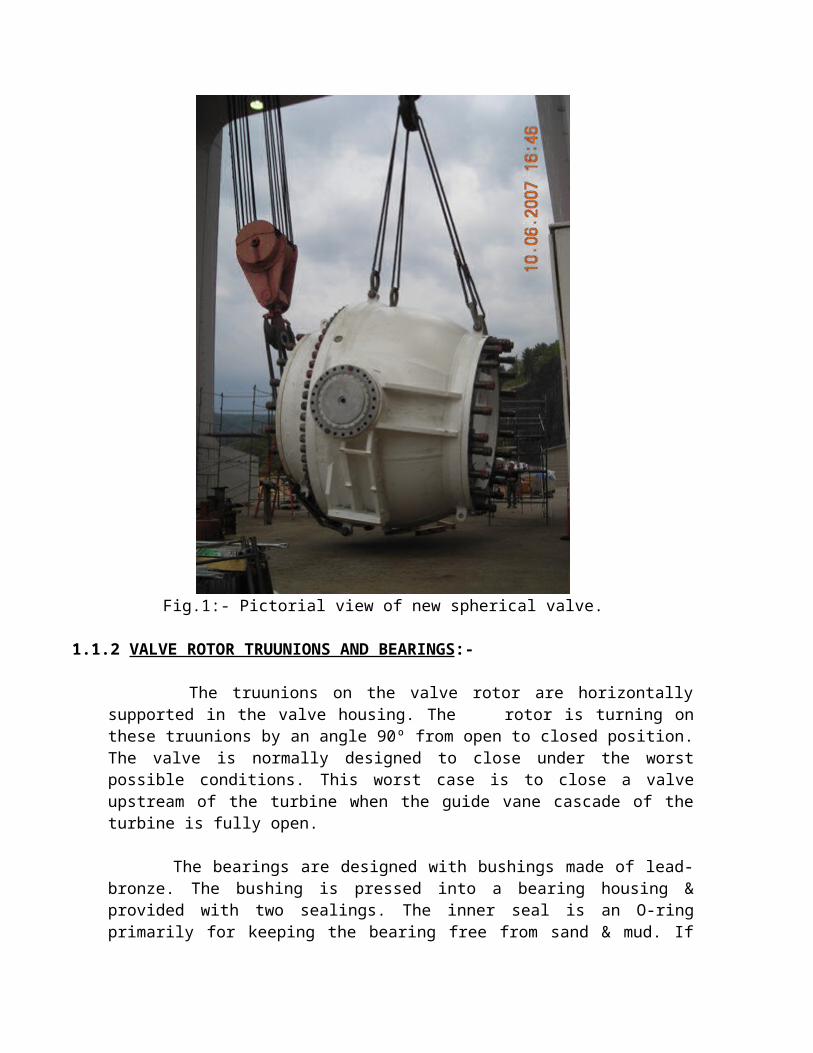
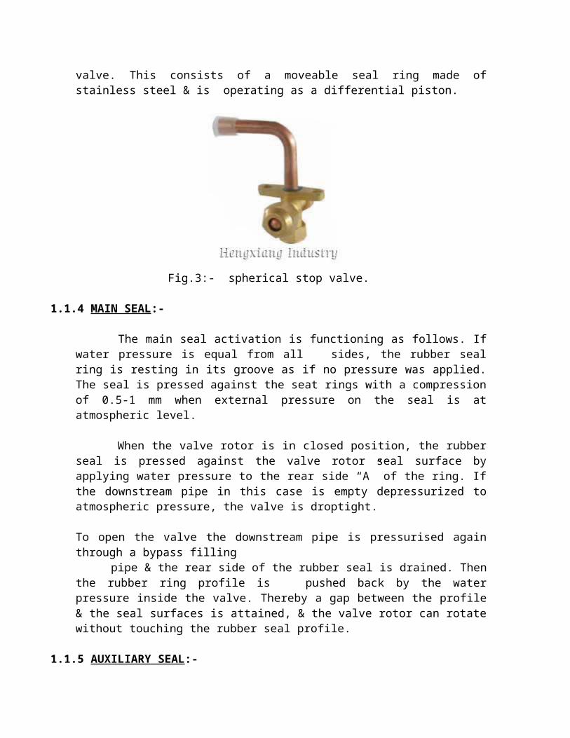
This consists of a moveable rubber profile contained in a stainless steel housing which is bolted to the intermediate ring. The auxiliary seal located on the upstream side of the valve. This consists of a moveable seal ring made of stainless steel & is operating as a differential piston.
Fig.3:- spherical stop valve.
1.1.4 MAIN SEAL:-
The main seal activation is functioning as follows. If water pressure is equal from all sides, the rubber seal ring is resting in its groove as if no pressure was applied. The seal is pressed against the seat rings with a compression of 0.5-1 mm when external pressure on the seal is at atmospheric level.
When the valve rotor is in closed position, the rubber seal is pressed against the valve rotor seal surface by applying water pressure to the rear side “A” of the ring. If the downstream pipe in this case is empty depressurized to atmospheric pressure, the valve is droptight.
To open the valve the downstream pipe is pressurised again through a bypass filling pipe & the rear side of the rubber seal is drained. Then the rubber ring profile is pushed
back by the water pressure inside the valve. Thereby a gap between the profile & the seal surfaces is attained, & the valve rotor can rotate without touching the rubber seal profile.
1.1.5 AUXILIARY SEAL:-
The auxiliary seal is activated by supplying water pressure to chamber”B”. The seal ring is then moved against the valve rotor seat ring. Chamber “C” is always connected to drain. The water pressure in the penstock & the spherical valve housing is pushing the seal ring back when chamber B is drained.
If the penstock has been drained with the auxiliary seal activated, the seal ring can be withdrawn by supplying water pressure to chamber C.
It is should be notified that the auxiliary seal must be activated only when the valve rotor is in closed position.
1.1.6 OPERATING MECHANISM:-
The opening & closing operation of the valve is carried out by one or two servomotors. the ring servomotor is mounted solely on the valve housing. Since the valve is designed to close against the flow at full turbine load, the valve rotor is subject to a large torque. this torque is transferred to the valve housing through the foundation of the servomotor. therefore the total closing torque is absorbed by the pipe & the valve.
This design of the valve operation facilitates the foundation & dimensioning of flanges & connecting pipes. The described operation mechanism design is most applied in Norway.
Another type of the operation mechanism is to use a linear servomotor to an arm which is wedged to the valve rotor truunions. In this case the servomotor & the valve housing have to be anchored to the surrounding foundations.
With this arrangement the adjoining pipes have to be dimensioned to withstand bending & torque forces in addition to the forces from the closed valve.
During valve closing however, the valve rotor is subject to a closing torque caused by the flow & a bearing friction torque caused by the support forces acting in the opposite direction. The sum of these torques will act partly in the closing direction & partly in the opposite direction. Therefore the servomotor must be operative for action both as brake & as motor for the valve rotor.
With this arrangement the adjoining pipes have to be dimensioned to withstand bending 7 torque forces in addition to the forces from the closed valve.
During valve closing however, the valve rotor is subject to a closing torque caused by the flow & a bearing friction torque caused by the support forces acting in the opposite direction. The sum of these torques will act partly in the closing direction & partly in the opposite direction. Therefore the servomotor must be operative for action both as a brake & as a motor for the valve rotor.
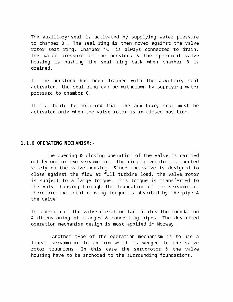
Fig.4:- Schematic view of high pressure spherical valve.
1.1.7 CONTROL SYSTEM:-
The control system is in principle built up. It is made up by a pilot control system located in “Spherical Valve Control Desk” & a main control system located in the “Control Cabinet”.
These two systems represent the automatic part of the control system. In addition the control system is provided with manually operated valves. By means of these valves it is possible to lock a closed spherical valve & to shut off the automatic control system to operate the spherical valve manually.
The control system of a spherical valve is normally operated with the pressure water from the penstock. The water is carefully filtered & only rustproof materials are used in control & shut-off valves. This system of operation has proved to be convenient & reliable.
Alternatively the servomotor may be operated by means of oil hydraulics. This way of operation however, will be more complicated & expensive.
Fig.5:- Pictorial View of Spherical valves.
2. BUTTERFLY VALVES:-
Butterfly valves are normally applied in front of low & medium head water turbines, i.e. heads up to 200 m. for high head power plants the butterfly valve is from time to time used as a closing device in inlet tunnels & alternatively as emergency closure valves.
Butterfly valves consist of mainly of ring shaped housing, the valve disc, operating mechanism & counter weight.
2.1 VALVE DISC:-
Inside the valve ring housing a revolving circular disc with two truunions, is supported in bearings in the ring housing. This valve disc is a plane with a packing around the circumference. In the fully open valve the disc plane is parallel to the water flow. A plane disc plate would however, in most cases be too weak to carry the load of the water pressure when the valve is closed. The disc therefore is often cast with a shape as a lens with internal ribs. For the larger sizes of these valves the disc may be made as a biplane structure to be sufficiently stiff & cause low flow losses. In this case the disc is usually welded from plates with integrally welded boss with trunnions.
The truunions are offset to the upstream side of the valve disc (considered in the closed position). In this way the seal between the disc & the valve housing ring may be a complete ring without joints at the truunions. This facilitates the achievement of complete tightness.
The disc trunnions are also offset somewhat either below or above the valve ring centre. This is called the butterfly valve’s eccentricity.
Fig.6:-Pictorial View of Butterfly valve.
2.2 BEARING:-
The valve disc has a bending tendency when it is in the closed position. Special bearings are therefore normally used for the trunnions. They are rotating in a bronze bearing with spherical shape.
The bronze bearing is supported in a bearing ring made of steel or cast iron with internal spherical shape. The bronze bearing is lubricated by grease, & may also be designed on the base of self lubricating material.
The seal around the trunnion is located in the bearing cover. The seal consists of an U-shaped rubber profile & an O-ring located outside this profile. Replacement of the bearing seals requires draining of the penstock.
2.3 SEAL:-
The valve housing ring contains a machined stainless seat. In a groove in the disc a rubber profile is inserted & kept in position by a clamp ring. With the disc in the closed position, the rubber is pressed outwards against the stainless seat by tightening the clamp ring screws. In this way the butterfly valve will be completely tight. If the seal should leak, this may be stopped under full upstream water pressure, by tightening the screws in the leaking part of the circumference.
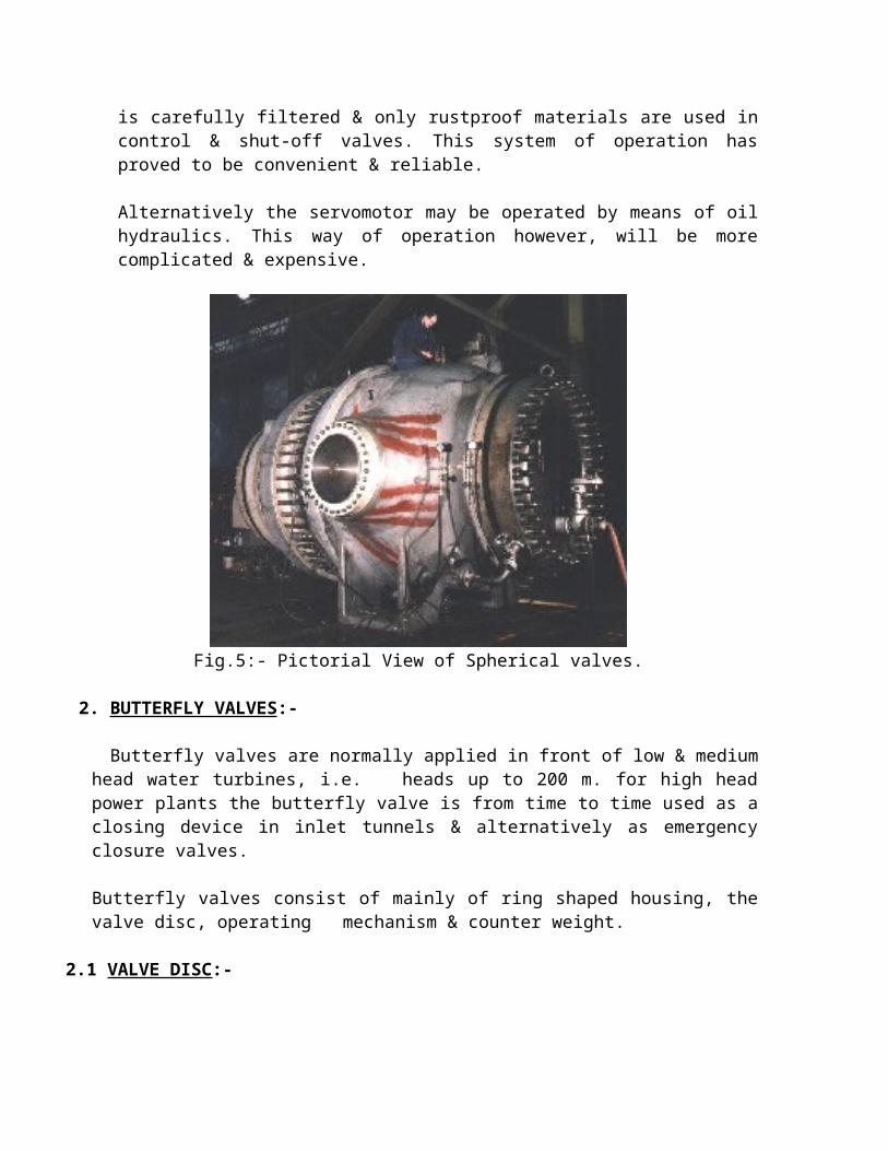
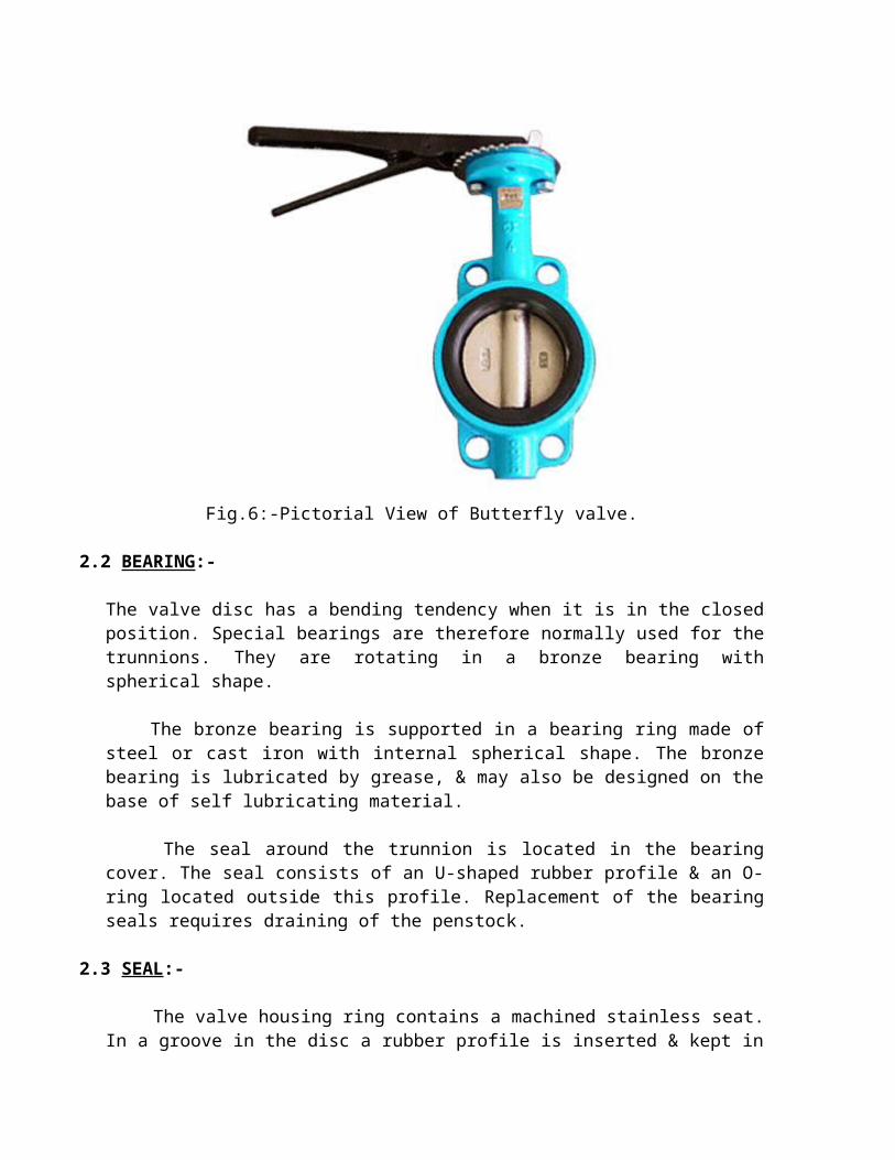
Fig.7:- Flange Type Butterfly Valve.
2.4 OPERATING MECHANISM:-
The butterfly valve shall be able to open & close under equalized water pressure on the disc sides as well as to close at full turbine discharge. In addition emergency closure valves shall close automatically in the case of penstock rupture.
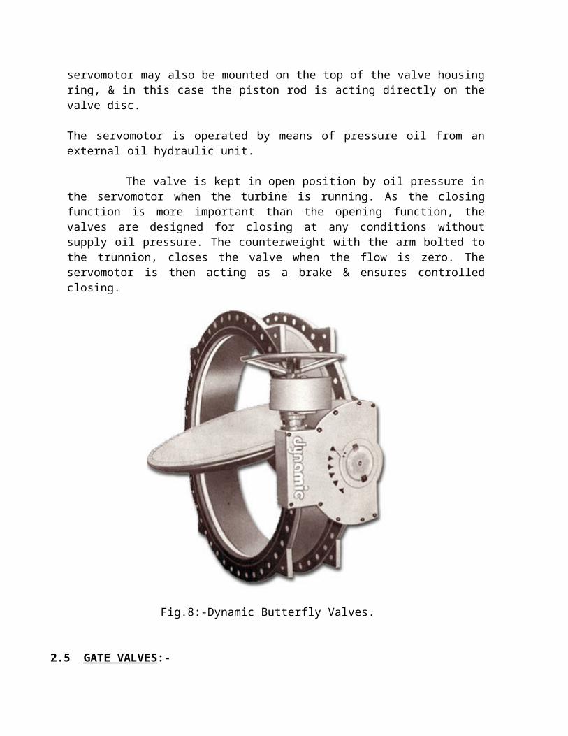
The opening is done by means of one (or two) servomotors. This may be mounted on the side of the valve & is acting on the counterweight arm which is bolted to the trunnion. The servomotor may also be mounted on the top of the valve housing ring, & in this case the piston rod is acting directly on the valve disc.
The servomotor is operated by means of pressure oil from an external oil hydraulic unit.
The valve is kept in open position by oil pressure in the servomotor when the turbine is running. As the closing function is more important than the opening function, the valves are designed for closing at any conditions without supply oil pressure. The counterweight with the arm bolted to the trunnion, closes the valve when the flow is zero. The servomotor is then acting as a brake & ensures controlled closing.
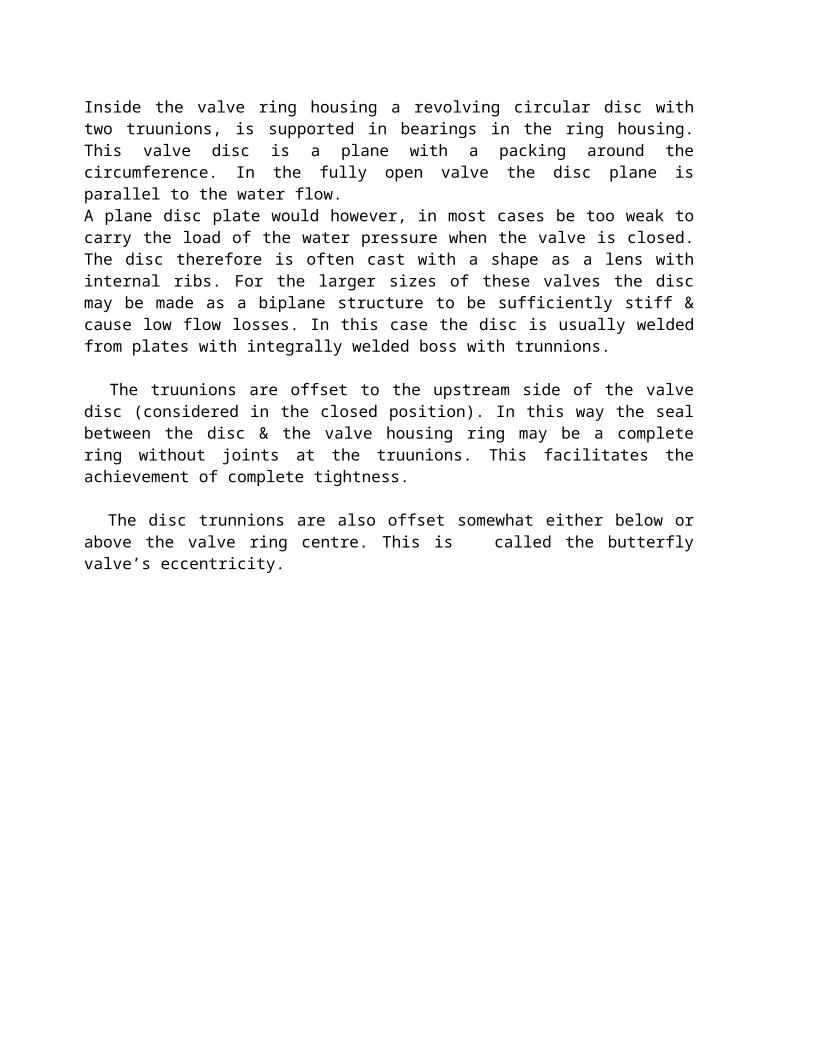
Fig.8:-Dynamic Butterfly Valves.
2.5 GATE VALVES:-
Gate valves are also applied as shut off valves in front of turbines. The spherical valves however, have come more & more in use instead. The reason is that the spherical valves need smaller space & cause lower flow losses than the gate valves. Therefore the gate valves are produced merely with diameters up to 750 mm. they are mostly produced with cast housing. For lower heads however, some of these valves are produced with welding housings too.
An ordinary gate valve design with a double acting servo cylinder common for gate valves is linear operated gate along a perpendicular to the longitudinal axis.
When the valve is fully open the gate is pulled away from the water canal. The movement of the gate is conducted by guides in the valve housing. When the valve is closed, the gate is pressed against the downstream stainless seal surface. The seal surface on the gate is also made of stainless material. In the closed position the water pressure acting on the gate is transferred directly to the valve seal. Increasing water pressure therefore results in increasing seal pressure.
The seal surface is inclined in relation to the gate closing direction. By closing movement the gate meets the seal surface just prior to fully closed position & slides against the seal surface
the last part of the movement. To avoid bending between piston rod & the gate, the gate is mounted to the piston with a certain freedom of movement.
For opening & closing of the valve the operating mechanism may be hydraulic, electrical or manual. On larger valves it is natural to use hydraulic control due to the large forces involved. For the hydraulic operation water pressure from the penstock or oil pressure from a hydraulic power unit is used.
If water pressure from the penstock is used, the cylinder wall has an inner layer of rustproof material. In this case the piston normally has a leather gasket against the cylinder wall. The water must pass a filter & be carefully cleaned before entering the cylinder. For smaller remote controlled valves electrical operation is an alternative.
Fig.9:- Schematic Diagram of gate valve.
Fig.10:- Detailed Sketch of Gate Valve.
3.RING VALVES:-
Ring valves have been used in many types of hydro power applications. In pump storage plants they are the most applied valve for closing the outlet of the pumps. However, they are applied also as pipe break valves, drain valves & safety valves.
A piston shaped closing device which is moved axially when opening & closing. The valve housing is partly conical & partly cylindrical, & together with the closing device it forms a ring shaped flow cross section. The closing device is supported in the housing by ribs.
The closing device consists of a piston with piston rod connected to a cylindrical member. This member has a seal ring fastened to the downstream end of it. The seal ring is made of stainless steel & designed to adapt to the housing seal ring in the closed position. The piston & piston rod are centered by a bushing at each end.
The design is operated by water pressure from the penstock through the connection A & B, & there is also a connection for emergency closing C. some ring valves are using oil as operating fluid. For this operation a hydraulic power unit is needed.
Ring valves installed in drain conduits are equipped with an auxiliary valve upstream & a pressure reducing device downstream of the ring valve. The Pressure reducing device is an energy dissipater connected with the downstream end of the ring valve.
The energy dissipater consists of concentric plates with a large number of small axial holes. By this arrangement the pressure drop at any point is kept below a level where cavitation may occur. For lower heads than 75 meters ring valves are delivered without pressure reduction device.
Fig.11 : Pictorial View of ring Valve.
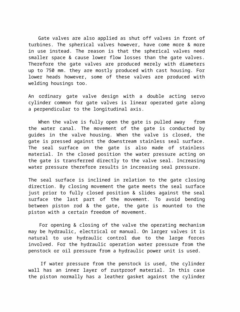
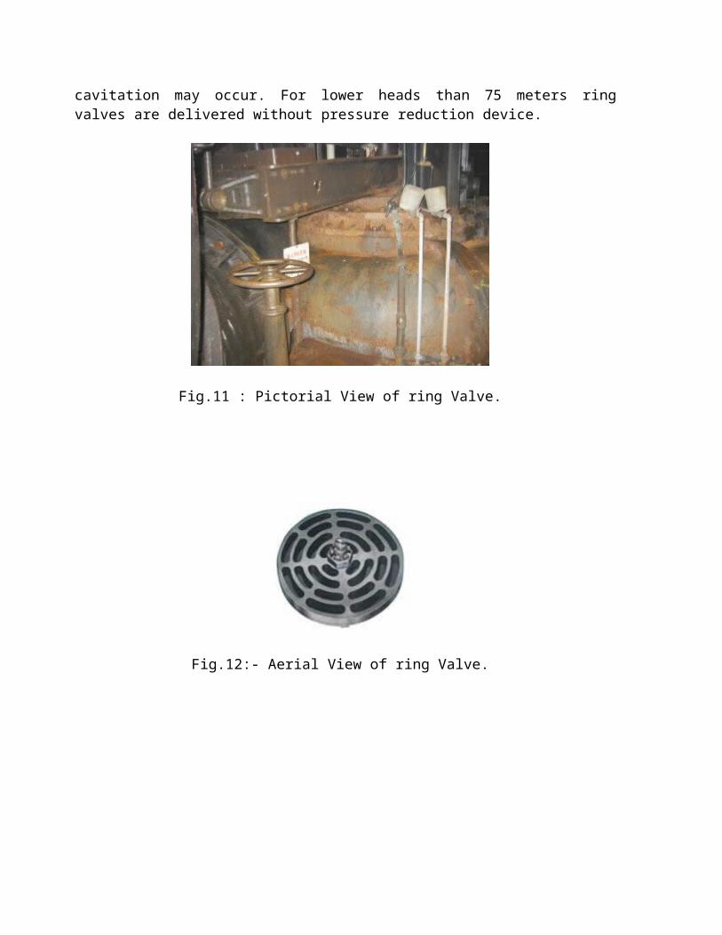
Fig.12:- Aerial View of ring Valve.
Fig.13:- Pictorial View Of check Valve.

Fig.14:- Schematic view of Guide ring valve.
4. BYPASS VALVE:-
A bypass valve is the opening/closing device in a pipe connecting the upstream & downstream side of the valve in the main conduit. This bypass is used to equalize the pressure on the two sides of the main valve to relieve the valve from large loads during normal opening & closing. The bypass is also used to fill the scroll casing of francis turbines & the distribution pipe of pelton turbines.
An example of the design of a hydraulically operated bypass valve where the valve needle is operated by a double acting servomotor. Opening & closing times are determined by orifices in the supply pipes to the servomotor.

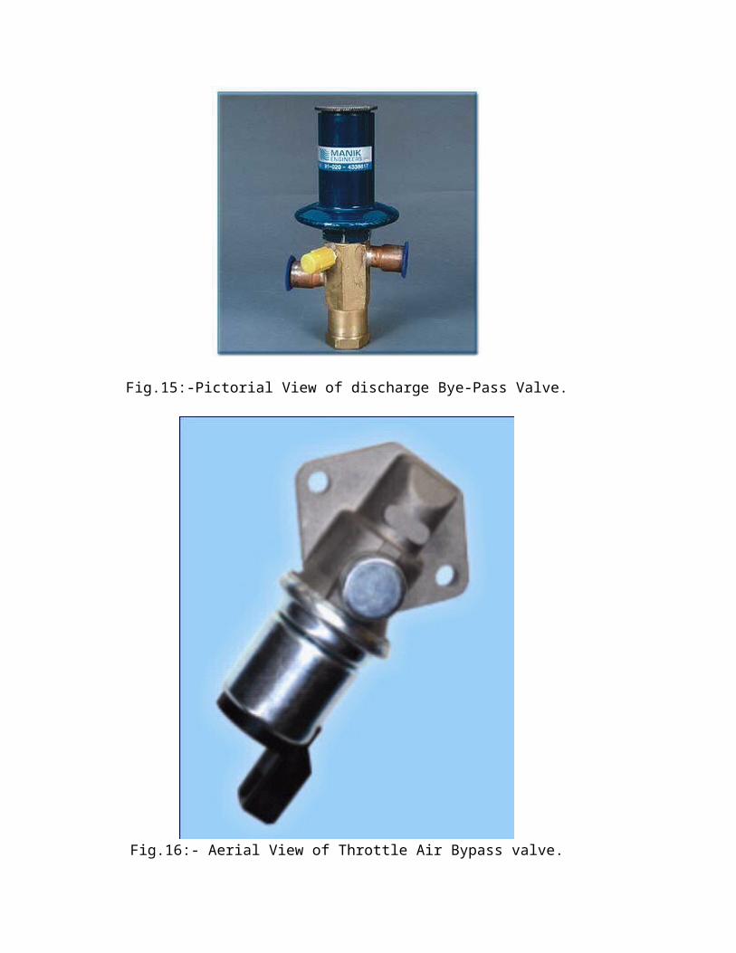
Fig.15:-Pictorial View of discharge Bye-Pass Valve.
Fig.16:- Aerial View of Throttle Air Bypass valve.

Fig.17:- Pictorial View of Bypass Valve.
4.1 GUIDELINES FOR INSPECTION OF VALVES:-
On valves & the connecting pipe ends the usual damages to be found are:
- Normal Wear.
- Mechanical Damages.
The valve housing & the closing body as well must be inspected. The access to the upstream side may be difficult to achieve, & the time interval between inspections must be determined on the base of the choice of materials, shape, probability of cavitation, vibrations or mechanical wear from sand & so on.
Spherical valves, butterfly valves & gate valves have different properties & patterns of damages. They consist however, of the same main components: valve housing, closing body & operating mechanism. The operating mechanism is normally a hydraulic servomotor operated either by water pressure or oil pressure.
4.2 SELECTION & DESIGN PARAMETERS:-
Turbine wicket gates are the first line of defense. The second line of defense is the emergency closure intake gate, or on a penstock with multiple units the turbine shut-off valve. In the case of a dedicated penstock with an emergency-closure intake gate, there is, in general, no need of a turbine shut-off valve (or turbine guard valve).
Compared with a spherical valve the butterfly valve is cheaper, & more compact resulting in lower crane & powerhouse costs, therefore, up to the limit of its head range, a butterfly valve is the preferred choice. One should always check out whether a butterfly can be used before resorting to a spherical valve. For instance, here is a cost comparision between a butterfly & a spherical valve of 3-m dia., for 200-m design head:
- BV Wt. of valve+ Op. = 75,000 Kg.- SV Wt. of valve+ Op. = 109,000 Kg.
Add the increased costs of a much larger valve chamber (approximately 3 times for a SV) & a larger valve chamber crane, & it becomes clear that a spherical valve is much more expensive.
The turbine shut-off valve designed for emergency closure, i.e. under maximum turbine flow. (It is very unusual to design the valve for full resulting from a burst penstock, although this is sometimes done as a design exercise). The maximum pressure resulting from water hammer effects should be used as the design pressure.
Valves should be sized to give a clear area of flow equal to the spiral case inlet diameter. Our practice is to estimate the spiral case inlet diameter, & specify the valve size we require. Twenty percent is a conservative estimate of the cross-sectional area occupied by the disc. To maintain the inlet cross sectional area requires a valve diameter of 1.095 times the inlet diameter.
For large valves the manufacturer should be encouraged to carry out model tests & improve on performance.
In general there is a tendency in our firm to prefer double-acting oil hydraulic servomotor with an independent h.p.u. for the turbine shut-off valve, rather than counterweights to ensure closure. However, using counterweights is a tried & reliable method to get fail-safe closure. Using an independent hpu for the turbine shut-off valve ensures that if the turbine hpu fails, the shut-off valve will close.
Usual turbine stress levels are specified, UTS/4 & YS/3. Usually butterfly valves have one service seal, although they can be provided with an upstream maintenance seal. In general the service seal is replaced by closing the intake gate on the penstock, & replacing service seals on all the butterfly valves on that penstock. Spherical valves are often provided with both maintenance & service seals. The maintenance seal is retractable, so relatively it will not wear. The maintenance seal should not last many service seals. The maintenance seal can be water pressure operated for actuation & retraction. of course the water should be highly purified to ensure that the actuating passages do not silt on; interlocks should be provided to ensure that the maintenance seal is retracted when the unit is returned to service.

4.3 SEAL PROPERTIES:-
Seals can be rubber (or other elastomer) sealing against corrosion resisting steel,or metal to metal (corrosion resisting usually steel).seal retainers & fasteners should be CRES.the seals should be adjustable without dewatering the penstock.the seals should be removable without removing the valve.
the maintenance seal, if specified, should be retractable & provided with interlocks to ensure that the seal is retracted before the valve is opened.
wherever possible rubber/elastomer seals are preferred because of their superior sealing. the hydraulic thrust should be carried into the penstock embedded in concrete(or rock). An
expansion & dismantling joint should be provided downstream of the valve. The valve body supports should permit some axial movement to accommodate elongation of the exposed penstock during valve closure.
in order to fill the downstream water passages bypass valves & pipes are provided. for large units the bypass valve would be hydraulically(or electrically) operated with hand wheel mechanism for manual operation. The bypass valve is often of the needle type with CRES needle & seat. Isolating valves upstream & downstream of the bypass valve are provided so that the bypass valve can be serviced while the turbine is on line. If the bypass valve size large, the manufacturer can be given the option to furnish two bypass valves, eg 2×18˝ valves instead of 1×24˝ bypass valve as at third extension.
Two automatic combination air inlet & vacuum release valves should be provided to exhaust air trapped in the spiral when the bypass line is operated for filling, & to admit air when the spiral is being drained with the turbine shut-off valve closed. each valve should be adequate with the other out of service.
Trunnion bearings should be of the self-lubricating type (used to be grease- lubricated). The trunnion & seal areas should be provided with renewable, CRES sleeves or suitable CRES coatings not less than 6 mm thick.
Valve leakage rates should be guaranteed by the manufacturer; he is requested to specify his guaranteed value in the tender data. The guaranteed value is checked in shop tests.
4.4 SHOP ASSEMBLY & TESTING:-
Shop assembly should be specified to prove that it all goes together. Shop operating tests should include at least 3 opening & closing cycles using the servomotors to be used with the valves. Shop hydrostatic test at 1.5 times design head for at least 30 minutes should be carried out on the valve body & bypass piping. Leakage tests should be carried out on the valve at the maximum design head for at least 30 minutes. The leakage rate must not exceed the value guaranteed in the tender data. any seal areas with a high concentration of leakage should be corrected, even if the total rate is within guarantee, & the leakage test should be repeated.
The hydraulic power unit (hpu) should be fully assembled & tested. The accumulator tank & its safety devices shall be tested in accordance with applicable codes (eg ASME). the

servomotors & hydraulic piping should be tested at 1.5 times maximum design pressure. The oil reservoir should be tested for leaks by hot oil or other means. Oil pumps should be operated & tested for capacity 7 pressure. controls & pressure relief devices should be tested. The hpu should be shipped ready for operation.
4.5 VALVE OPERATING SYSTEMS:-
Water operated servomotors have been used. A sufficiently high head is required, & the servomotor parts have to be made of CRES in order to prevent corrosion. The main advantage of using the available water head is its reliability. With the great increase in the reliability of hydraulic (i.e. oil) systems, & their competitive cost, nowadays most valve operating systems are hydraulic.
Opening & closing times should be independently adjustable in the 30 to 120 s range. Adjustment should be by means of valves which can be locked after adjustment rather than by orifice plates. Valve operating servomotors are slow moving, so cushioning is in general not required.
Valves may be operated by one or two servomotors; larger valves should perhaps be operated by two servomotors, although manufacturers claim that even the largest valves can be operated by one servomotor. The single servomotor arrangement is usually cheaper. Servomotors can also be conveniently mounted on the valve body.
The nominal design oil pressure should be selected by the manufacturer in the range of 70 to 105 kg/cm2.
Hydraulic systems have one or two main pumps, one main & the other on standby (if 2 pumps), & a booster pump. The pumps are of the rotary vane or screw type with direct –connected electric motors,& sized to replenish the full working oil volume of the accumulator system in not more than 10 minutes. The capacity of the oil reservoir should be not less than that required to contain all of the oil that can be discharged back into the reservoir. The accumulator system shall be as required to provide 4 full strokes of the operating cylinder(s) without replenishment by the oil pumps. The piping shall be sized for a maximum oil velocity of 5 m/s for servomotor travel at the max. rate.
The operating mechanism should include suitable stops to limit the disc travel at the open & close positions, & a manually operated locking mechanism for holding the disc in the closed position. A locking pin capable of holding the valve in the closed position against the maximum servomotor force should be provided. The locking pin should engage/disengage the disc by means of a hand wheel. Provision should be made for padlocking. Interlocks should be provided to coordinate the operating sequence.
4.6 ACTUAL HEAD LOSS AFTER IMPROVEMENT TO MODEL:-
Inlet lattice valve – Dia on seat with K= Head Loss & αº = Op. Angle. ------------ V2/ 2g It is obtained with the following characteristic:-
αº K ----- -----
Fully Open- 0 0.076 10 0.28 20 1.35 30 3.50 40 9.5 50 25 αº K
------ -------
60 75 70 285
4.7 SAFETY FACTORS & DESIGN STRESSES:-
4.7.1 GENERAL:-
The maximum allowable stresses in certain types of materials used in the equipment are specified herein. the contractor be responsible for an adequate design based on factors proven safe in practice & shall used lower working stress wherever he deems necessary or desirable or where he deems deflection to be the controlling design criterion.
4.7.2 MAXIMUM ALLOWABLE STRESSES:-
Generous factors of safety shall be used throughout design. Due consideration shall be given in the design of parts subject to alternating stresses, fatigue vibration, impact, or shock. Under the most severe conditions of loading expected in normal operation, stresses in materials shall not exceed the values listed below. Maximum shear stresses in cast iron shall not exceed 21 MPa. Maximum shear stresses in other ferrous materials shall not exceed 60% of the allowable stresses in tension, except that the maximum torsional shear stresses in the shafting, including turbine& generator shafts * wicket gate stems, shall not exceed 50% of the allowable stress in tension. For temporary overloads exceeding the maximum turbine output under the maximum net head, unit stresses shall not exceed one- half the yield strength. The design stresses for materials not listed herein shall be selected by the contactor, but the maximum stresses in tension or compression shall not exceed one-third of the yield strength nor one-fifth of ultimate tensile strength. Under the maximum runaway speed conditions, or under hydrostatic test conditions, or generator maximum unbalanced transient

forces caused by short-circuits, the stresses shall not exceed two-thirds of the yield strength at the breaking point of the shear pins.
MATERIAL MAXIMUM ALLOWABLE STRESS
In Tension In compression
Grey Cast Iron 1/10 U.T.S. 70 MPaCarbon Cast Steel The lesser of The lesser of 1/3 Y.S. 1/5U.T.S
& Alloy Cast Steel 1/5 U.T.S. 1/3 Y.S.
Carbon Steel Forgings 1/3 Y.S. 1/3 Y.S.
MATERIAL MAXIMUM ALLOWABLE STRESS
In Tension In compression
Carbon-steel plate for 1/4 U.T.S. 1/4 U.T.S.Important steel carrying Parts.
High-strength plate steel for 1/3 Y.S. 1/3 Y.S.highly stressed parts
NOTE:-
U.T.S. = Ultimate Tensile Strength. Y.S. = Yield Strength.
4.7.3OPERATING OVERLOAD COMBINATIONS:-
Operating overload combinations shall be obtained by either one of the following summations of applicable loads:-
Loads of static origin, loads due to guiding effort & water turbulence, extraordinary blocking load in raising or lowering.
Loads of static origin, earthquake loading.
4.7.4 LOADING ON DOGGING DEVICES:-
Normal loading on a dogging device shall be 150% of the load to be dogged. This load shall be considered evenly distributed between the dogging members.

Overload on a dogging device shall be the weight to be dogged, suspended on only one dogging member, considering the other dogging member(s) disengaged.
4.7.5 ALLOWABLE STRESSES:-
4.7.5.1 STRESSES IN STEEL STRUCTURES:-
The allowable stresses for structural steel under normal loading conditions shall be those given in the AISC “Specifications for the Design, Fabrication & Erection of structural steels for buildings” but shall not be higher than the following percentages of the yield strength of the respective material used;
Tension (On net section at holes) - 45% Bending (Tension & Compression on extreme Fibers of unsymmetrical members) - 60% Bending (Tension & Compression on extreme Fibers of symmetrical members) - 60%
Shear (On gross section of beam & plate girder webs) - 40%Bearing on contact area of machined surfaces - 80%
For overload conditions, the allowable stresses given for normal loading condition may be increased by 33.3% except that the bearing stress shall not exceed 90% of the yield strength.
The equivalent stress resulting from combining bi-axial or tri-axial stresses may be 25% higher than the allowable monoaxial stress, but for all loading conditions not more than 80% of the yield strength of the material.
4.7.5.1.1 MECHANICAL COMPONENTS:-
4.7.5.1.2 GENERAL:-
The working stresses, bearing pressures & other design criteria for mechanical components including shafts, pins & gears shall be based on consideration of functional requirements, dynamic loadings, impact & stress conditions( or rated capacity) in no case shall exceed 1/5 of the ultimate strength of the materials involved. The working stresses for overload may be increased to 80%, & those for overload caused by stalled conditions may be increased to 90% of the minimum yield strength or elastic limit of the materials used.
4.7.5.1.3 GEARS:-
Gears shall be designed to meet the requirements of the applicable AGMA standards. At rated loads & speeds, the durability & strength rating of the gears shall be based on a service factor of one.
4.7.5.1.4 BEARINGS & BUSHINGS:-
4.7.5.1.5 GENERAL:-
Average bearing pressures shall be calculated by dividing the bearing load by the effective projected area of the bearing.
Maximum local bearing pressures shall be calculated for unsymmetrically loaded bearings & bushings assuming non- uniform linear pressure distribution along the length of the bearing. When calculating maximum local bearing pressures due to shaft deflection, it shall be assumed that the steel shaft is incompressible & bearing Pressures are proportional to the compression of the bearing material.
5. DIMENSIONING CRITERIA:-
5.1 NORMAL OPERATION: OVER PRESSURE:-
For cast steels, the max. Permissible stress is:
σmax. = min. (R/5, E/3)
For flat steels, the max. Permissible stress is that defined by the ASME code.
According to APPENDIX P, this stress is;
σmax. = min. (R/4; 2/3 E)
5.2 EXCEPTIONAL OPERATION: OVER PRESSURE DUE TO EARTHQUAKE:-
The permissible primary stress is:
σmax. = 2/3 E.
5.3 EXCEPTINAL OPERATION: TEST PRESSURE:-
The permissible primary stress is:
σmax. = 2/3 E.

5.4 DIMENSIONING OF TRUNNIONS:-
5.4.1 SPECIFIC PRESSURE:-
The outer shrunk-on diameter of the trunnion is: D=1180 mm.
The trunnion length is: L= 945 mm.
The specific pressure is:
P = ρg H. π D j2
------------------
4 LD
5.4.2 LEAKAGE RATES:-
Valve type, function Working Factor Test Contact Leakage Specific Project, year, mfr. Pressr. × n Press.r Ø Rate Leakage Psi (bar) psi (bar) ft (mm) (l/h) Rate (l/h per
of contact)
Lattice disk, b’fly, 15.94 1.5 23.9 7340 692 0.0300Turbine inlet valve, (2000- bid guar.)
Lattice disk, b’fly 15.94 1.5 23.9 3550 1000 0.0897Turbine ressn relief (1000- bid guar.)Valve.
Fixed-Cone valve 15.94 1.5 23.9 (300-bid guar.)
Static Head Overpressure Test pressure Hm 135.64 162.5 243.7 Hft 445 533 799.5 p 25.2 MPa 30.2 MPa 45.4 MPa


![7 Valves - EADIPS FGR...defined in EN 736-1 [7.1-01]. Table 7.1.1-01 contains a classification of valves according to their functional features. Isolating valves are basically intended](https://img.dokumen.tips/doc/110x75/5e8819cfe68dc730af235aef/7-valves-eadips-fgr-defined-in-en-736-1-71-01-table-711-01-contains.jpg)