Embed Size (px)
Citation preview

CC1N7696en 25.04.2005
Building TechnologiesHVAC Products
7696
VALVEGYR® Valve Proving System for
automatic Shutoff Valves LDU11...
The LDU11... valve proving system is designed for use with shutoff valves in con-nection with gas burners and gas appliances. In the event of inadmissible leakage, the system prevents the burner from starting up. The LDU11... system conforms to the requirements of EN 1643 covering automatic shutoff valves for use with gas burners and gas appliances to EN 161. The LDU11... and this Data Sheet are intended for use by OEMs which integrate the valve proving system in their products.

2/16
Building Technologies CC1N7696en HVAC Products 25.04.2005
Use
The LDU11... is designed for automatic gas valve proving (leakage test) based on the pressure proving principle. It is for use on gas-fired combustion plant with or without vent pipe to atmosphere. In the case of plants with no vent pipe where EN standards apply, the notes given in «Connection examples without vent pipe to atmosphere» must be observed. Used in connection with 1 or 2 commercially available pressure switches, valve proving is automatically initiated with every burner startup, either - prior to burner startup - during the prepurge time if it lasts a minimum of 60 seconds - immediately after a controlled shutdown, or - on completion of the burner control’s control sequence, e.g. at the end of the post-
purge time The valve proving test is based on the 2-stage pressure proving principle: 1. First test phase: The valve on the mains side is tested by evacuating the test space
and by monitoring the atmospheric pressure in it. 2. Second test phase: The valve on the burner side is checked by pressurizing the test
space and by monitoring the gas pressure. If the pressure increases excessively during the first test phase called «Test1», or de-creases excessively during the second test phase called «Test2», the valve proving sys-tem will inhibit burner startup and initiate lockout. In that case, the lockout reset button will light up to indicate the fault. Remote indication of the fault is also possible. A program indicator, which stops whenever a fault occurs, indicates which of the valves is leaking. The valve proving system can be reset either on the unit itself or via an electric remote reset facility.
Warning notes
To avoid injury to persons, damage to property or the environment, the following warning notes should be observed. Do not open, interfere with or modify the control unit. • All activities (mounting, installation and service work, etc.) must be carried out by
qualified staff • Before performing any wiring changes in the connection area of the LDU11..., com-
pletely isolate the unit from the mains supply (all-polar disconnection) • Ensure protection against electric shock hazard by providing adequate protection for
the valve proving system’s connection terminals • Ensure that wiring is in an orderly state • Press the lockout reset button only manually (applying a force of no more than 10 N)
without using any tools or pointed objects • Do not press the lockout reset button on the unit for more than 10 seconds
since longer presses will destroy the lockout relay • Fall or shock can adversely affect the safety functions. Do not put such units into
operation, even if they do not exhibit any damage Mounting notes
• Ensure that the relevant national safety regulations are complied with

3/16
Building Technologies CC1N7696en HVAC Products 25.04.2005
Installation notes
• Live and neutral conductors must not be interchanged
Commissioning notes
• Prior to commissioning, ensure that wiring is in an orderly state
Standards and certificates
Conformity to EEC directives - Electromagnetic compatibility EMC (immunity) - Directive for gas appliances
89 / 336 EEC 90 / 396 EEC
ISO 9001: 2000 Cert. 00739
ISO 14001: 1996 Cert. 38233
Certified complete with plug-in base:
Type reference
LDU11.323A17 --- x x x --- x LDU11.323A27 --- x --- x --- x LDU11.523A17 x --- x x x --- LDU11.523A27 x --- --- x --- ---
Service notes
• Each time a unit has been replaced, ensure that wiring is in an orderly state
Disposal notes
The unit contains electric and electronic components and must not be disposed of to-gether with domestic waste. Local and currently valid legislation must be complied with.

4/16
Building Technologies CC1N7696en HVAC Products 25.04.2005
Mechanical design - Plug-in design - Exchangeable unit fuse (including spare fuse) - Made of impact-proof and heat-resistant black plastic - Lockout reset button with viewing window showing:
– The fault signal lamp – The lockout indication - Coupled to the program spindle - With transparent lockout reset button - Easy-to-remember symbols indicating the type of fault and the time lockout occurred - Synchronous motor of the sequence switch with gear train and step action sequence switch - Camshaft with 15 nonadjustable cams - Program indicator at the head of the camshaft - 1 main and 1 auxiliary relay - Lockout relay can be electrically reset from a remote location and provides the «Lockout» and «Reset» functions - Unit fuse and spare fuse
All electrical components are interconnected via printed circuits.
Type summary
Type reference Mains voltage t3 t4 LDU11.323A17 AC 100...110 V 2.5 s 2.5 sLDU11.323A27 AC 220...240 V 2.5 s 2.5 sLDU11.523A17 ¹) AC 100...110 V 5 s 5 s LDU11.523A27 ¹) AC 220...240 V 5 s 5 s t3 Filling the test space t4 Evacuating the test space ¹) Valve opening times do not conform to EN 1643
Ordering Valve proving system LDU11... (without plug-in base) refer to «Type summary» Plug-in base not included in the delivery, must be ordered as a separate item! Connection accessories for medium-capacity refer to Data Sheet N7230 burner controls - Plug-in base AGM11 with Pg11 threads for cable entry glands - Plug-in base AGM11.1 with M16 threads for cable entry glands
PTC resistor (AC 230 V) AGK25- For load on terminal 4 of LMG2...
Valve proving system LDU11...
Housing
Legend

5/16
Building Technologies CC1N7696en HVAC Products 25.04.2005
Technical data
Mains voltage - LDU11.323A27 - LDU11.323A17
AC 220 V –15 %...AC 240 V +10 % AC 100 V –15 %...AC 110 V +10 %
- LDU11.523A27 ¹) - LDU11.523A17 ¹)
AC 220 V –15 %...AC 240 V +10 % AC 100 V –15 %...AC 110 V +10 %
¹) Valve opening times do not conform to EN 1643 Mains frequency 50...60 Hz ±6 % Unit fuse (built-in) T6.3H250V to DIN EN 60 127 Primary fuse (external) max. 10 A (slow) Weight approx. 1000 g Power consumption - During the test - During operation
approx. AC 3.5 VA approx. AC 2.5 VA
Mounting position Optional Degree of protection IP 40 (to be ensured through mounting),
except the connection area (terminal base)Safety class I Perm. input current at terminal 1 max. 5 A (peak current 20 A / 20 ms) Perm. current rating of control terminals max. 4 A (peak current 20 A / 20 ms) Required current rating of pressure switch «DW»
min. 1 A, AC 250 V
Storage DIN EN 60721-3-1 Climatic conditions class 1K3 Mechanical conditions class 1M2 Temperature range -20...+60 °C Humidity < 95 % r.h. Transport DIN EN 60 721-3-2 Climatic conditions class 2K2 Mechanical conditions class 2M2 Temperature range -50...+60 °C Humidity < 95 % r.h. Operation DIN EN 60 721-3-3 Climatic conditions class 3K5 Mechanical conditions class 3M2 Temperature range -20...+60 °C Humidity < 95 % r.h. Condensation, formation of ice and ingress of water are not permitted!
General unit data LDU11...
Environmental conditions

6/16
Building Technologies CC1N7696en HVAC Products 25.04.2005
Function
During the first phase of the valve proving test called «Test1», atmospheric pressure must exist in the length of pipe between the valves to be tested. In plants with a vent pipe to atmosphere, atmospheric pressure is available if the valve proving test is made prior to or during the prepurge time. In plants without vent pipe, atmospheric pressure is made available as the valve proving system opens the valve on the burner side during the time «t4». If the valve proving test is performed after burner operation, the valve on the burner side after the controlled shutdown can be kept open until «t4» has elapsed, thus lowering the pressure in the test space and making certain its gas content is burnt off in the combus-tion chamber during the postpurge time. Prerequisite for this procedure is a suitable control program of the burner control as pro-vided by burner controls type LFE..., LFL..., LGK... or LEC... The test space is closed off after evacuation. During the first test phase «Test1», which then follows, the LDU11... checks with the pressure switch if the atmospheric pressure in the test space is maintained. If the valve on the mains side is leaking, causing the pressure to rise above the switching point of the pressure switch, the LDU11... will trigger an alarm and initiate lockout. The program indicator then stops to indicate «Test1». If the pressure does not increase because the valve closes correctly, the LDU11... con-tinues its program with the second test phase «Test2». For that purpose, the valve on the mains side is opened during «t3» so that the test space is pressurized («filling» the test space). During the second test phase – if the valve on the burner side is leaking – this pressure must not fall below the switching point of the pressure switch. If it does, the LDU11... will initiate lockout also, thus preventing the burner from starting up. On successful completion of the second test phase, the LDU11... closes the internal control loop between terminals 3 and 6 (circuit path: terminal 3 - contact «ar2» - terminals 4 and 5 - contact III - terminal 6). This control loop is normally included in the burner control’s start control loop. After the control loop has been closed, the programming mechanism of the LDU11... returns to its start position to switch itself off. During these so-called idle steps, the positions of the programming mechanism’s control contacts remain unchanged.

7/16
Building Technologies CC1N7696en HVAC Products 25.04.2005
Program and lockout indicator
In the event of lockout, the programming mechanism stops and thus the position indicator fitted to the spindle of the mechanism. The symbol that stops above the reading mark indicates the test phase during which lockout occurred and also gives the number of programming steps completed from the start of this test phase (1 step = 2.5 seconds). ► Start position = operating position
In plants without vent valve: Evacuation of test space by opening the valve on the burner side
Test1 «Test1» with atmospheric pressure (valve proving test on the mains side)
Filling the test space by opening the valve on the mains side Test2 «Test2» with gas pressure (valve proving test on the burner side) I I I Idle steps until programming mechanism switches itself off ► Operating position = start position for the next valve proving test In the event of lockout, all terminals receiving voltage from the LDU11... will be deener-gized, except terminal 13, which is used for lockout indication. After a reset, the programming mechanism automatically returns to its start position to immediately program a new valve proving test. Do not press the reset button for more than 10 seconds. A power failure prior to evacuating the test space does not cause the control sequence to change. If a power failure occurs after the evacuation, the valve proving test will not be continued when power is restored, but the programming mechanism first returns to its start position and then performs the complete valve proving test.
Meaning of the sym-bols:
Note
Control sequence after a power failure
8/16
Building Technologies CC1N7696en HVAC Products 25.04.2005
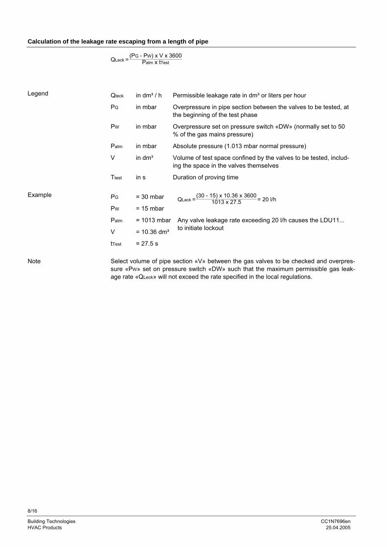
Calculation of the leakage rate escaping from a length of pipe
QLeck =(PG - PW) x V x 3600
Patm x tTest Qleck in dm³ / h Permissible leakage rate in dm³ or liters per hour
PG in mbar Overpressure in pipe section between the valves to be tested, at the beginning of the test phase
PW in mbar Overpressure set on pressure switch «DW» (normally set to 50 % of the gas mains pressure)
Patm in mbar Absolute pressure (1.013 mbar normal pressure)
V in dm³ Volume of test space confined by the valves to be tested, includ-ing the space in the valves themselves
Ttest in s Duration of proving time PG = 30 mbar
PW = 15 mbar QLeck =
(30 - 15) x 10.36 x 36001013 x 27.5 = 20 l/h
Patm
V
= 1013 mbar
= 10.36 dm³
Any valve leakage rate exceeding 20 l/h causes the LDU11... to initiate lockout
tTest = 27.5 s Select volume of pipe section «V» between the gas valves to be checked and overpres-sure «PW» set on pressure switch «DW» such that the maximum permissible gas leak-age rate «QLeck» will not exceed the rate specified in the local regulations.
Legend
Example
Note

9/16
Building Technologies CC1N7696en HVAC Products 25.04.2005
Connection diagram
Legend AL Alarm signal for «leaking valve» AR Main relay with contacts «ar...» AS Unit fuse (built-in) BR Lockout relay with contacts «br...» DW Pressure switch for valve proving test (does not replace the gas pressure switch used to signal lack of gas) EK1 Lockout reset button EK2 Remote lockout reset button GP Gas pressure switch (for lack of gas) HR Auxiliary relay with contacts «hr...» L1 Lockout warning lamp (built-in) Si External primary fuse SK Control contact (for initiating the valve proving test) SM Synchronous motor of programming mechanism 1) Do not press «EK...» for more than 10 seconds
M~
L
EK2
18 1
SK1)
AS ar2
3 4 5
III
6a bI
8a b
V
10 12 19 23 20a b a b
XI hr1
22 21 24
hr2 HR
ba
XIII
a bIX
ar1
br1
IV
15 14
16 17
P GP
DW
Atm. GasVII
b aVIII
a bar3
b aVI
AR
br2
BR
L1EK1
1)
13
ALN
2 7 9 11
SM
LDU11
7696a15/0204
Si
Sequence diagram
Legend t1 22.1 s First test phase with atmospheric pressure t2 27 s Second test phase with gas pressure For LDU11.323... t3 2.5 s Filling the test space t4 2.5 s Evacuating the test space For LDU11.523... t3 5 s Filling the test space t4 5 s Evacuating the test space t5 66.3 s Total duration of valve proving test until burner is released t6 7.4 s Interval from start to energizing main relay «AR» t20 22.1 s Running time of programming mechanism until it switches itself off in the operating = start posi- tion (idle steps) A Gas valves controlled to evacuate the test space B Gas valves controlled to fill the test space C Vent valve, normally open; closed during valve proving test from the beginning of «Test1»
A B C
I
III
IV
V
VI
VII
VIII
IX
XI
XIII
AR
Test1 Test2
7 8
5 6
9
9 10
11 15
11 12
t20
t4 t1
t6
t3 t2
t5
7696b01e/0601
ab
ab
ab
ab
ab
ab
ab
Output terminalscontrolled by thecontrol unit orelectricallyconnectedProgram indication

10/16
Building Technologies CC1N7696en HVAC Products 25.04.2005
Connection examples with vent pipe to atmosphere using burner controls type LGB2..., LGB3... or LGB4... For other connections, refer to the connection diagram of the relevant burner control.
Valve proving test prior to burner startup Valve proving test following immediately the controlled
shutdown
LDU1117
DW2
C
54
hr1
GP231116
15
EB
6
IIIar2
3
SB / R / W
N
1
12LGB2.../3.../4.../LMG2...
HL
hr2XI
2014 1912 22
53 4
A2A1M
N
AL
13
2421
10
7696a05/0403
N
L
LDU11
22
542
C
hr1
7
B
11
E
12
P
III
11614 15
DW
ar2
17 3
LGB2.../3.../4.../LMG2...
H
6hr2
19 23 20
I
8 12
XI
SB / R / W
A2 A1
5
GP
3
M
N13
AL
21 24
4
7696a06/0703
AGK25 3)
³) Only in connection with LMG2...
Plants with vent pipe to atmosphere
GPE
C
BDW
LDU
A A2A1
C
DW
LDU
BGP
E
7696s01/0695 Connection examples with vent pipe to atmosphere using burner controls type LFE..., LFL... or LGK..., or the control unit LEC... Valve proving test during the prepurge time (min. 60 sec-onds) and following immediately the controlled shutdown in plants with vent pipe to atmosphere. Delay on make of relay d > 2 seconds. 2) Expanding flame burner or interrupted pilot burner
Valve proving test following immediately the controlled shutdown
2) Expanding flame burner or interrupted pilot burner
N
LDU11
hr2
GP C
1415
18 1EK2
217
166
III
53
ar2
4
BE
11
201912
hr1XI
238
I7
10
V9
14
W
2
d
LFE1LEC1
LFL1...LGK16...
18 199
12 134
LP
8
5
RN
4 5°/10°°
18°/17°°
A
AL
22
13
2421
N
7696a10/0401
DW
2)
2)
LDU11
hr2
GP CN
BE
6
W
1415
18 1
1716
III
53
ar2
4
2
EK2
4
LFE1LEC1
LFL1...LGK16...
8
R
N
11
201912
hr1XI
23
I
7
10
V
9
8
5°/10°°
18°/17°°
A
9
5
AL
7696a11/0401
22
13
2421
N
DW
2)
2)
11/16
Building Technologies CC1N7696en HVAC Products 25.04.2005
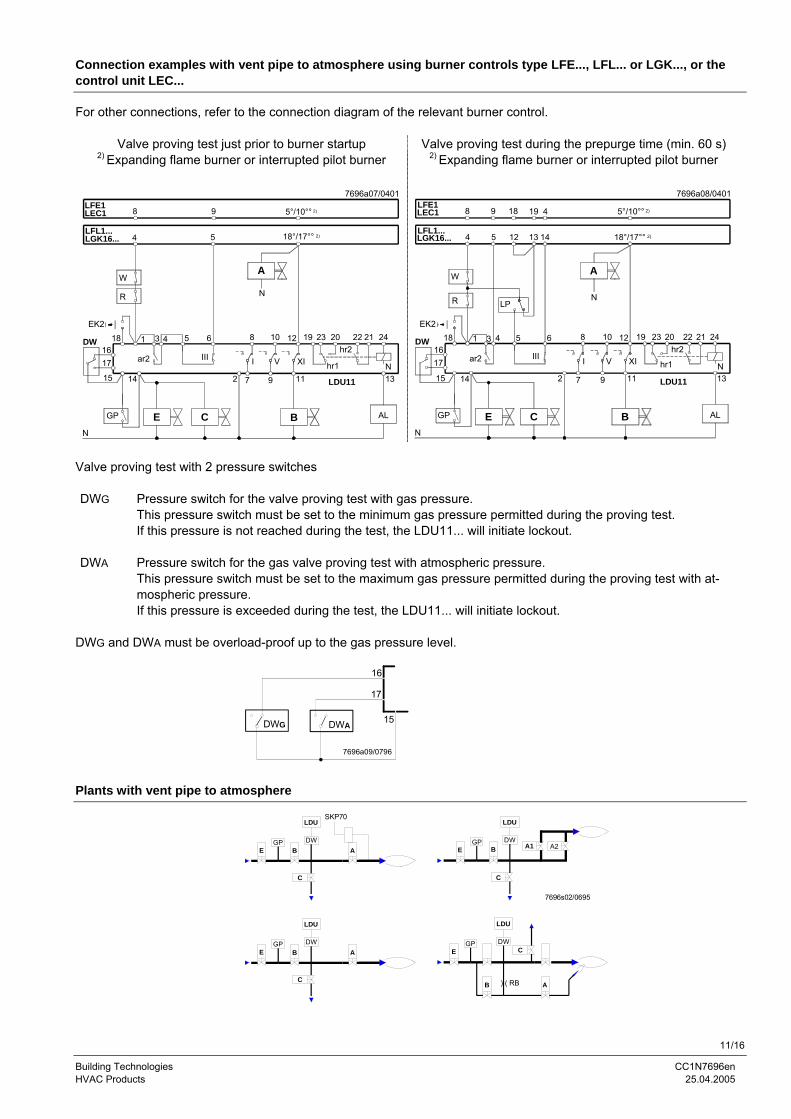
Connection examples with vent pipe to atmosphere using burner controls type LFE..., LFL... or LGK..., or the control unit LEC...
For other connections, refer to the connection diagram of the relevant burner control.
Valve proving test just prior to burner startup Valve proving test during the prepurge time (min. 60 s) 2) Expanding flame burner or interrupted pilot burner
2) Expanding flame burner or interrupted pilot burner
N
LDU11
hr2
GP E C B
5
W
1415
618 1 4
ar2 III
5
EK2
1716
3
8
4
9LFE1LEC1
LFL1...LGK16...
R
11
19
hr1XI
202312
9
V
10
7
8
I
2
N
5°/10°°
18°/17°°
A
AL
13N
242122
7696a07/0401
DW
2)
2)
N
LDU11
hr2
GP CE B
4
14
W
1415
618 1 3
ar2 III
5EK2
1716
4
LP
8 18 19
4
9
5 12 13
LFE1LEC1
LFL1...LGK16...
R
11
201912
hr1XI
23
N
9
10
V
7
8
I
2
5°/10°°
18°/17°°
A
AL
22
13
2421
N
7696a08/0401
DW
2)
2)
Valve proving test with 2 pressure switches DWG Pressure switch for the valve proving test with gas pressure.
This pressure switch must be set to the minimum gas pressure permitted during the proving test. If this pressure is not reached during the test, the LDU11... will initiate lockout.
DWA Pressure switch for the gas valve proving test with atmospheric pressure.
This pressure switch must be set to the maximum gas pressure permitted during the proving test with at-mospheric pressure. If this pressure is exceeded during the test, the LDU11... will initiate lockout.
DWG and DWA must be overload-proof up to the gas pressure level.
16
17
DWG DWA15
7696a09/0796
Plants with vent pipe to atmosphere
GPE
DWC
B A
A1
LDU
C
DWB
GPE
LDU
A2
7696s02/0695
) ( RB
GPE
C
BDW
LDU
A
GPE
C
BDW
LDU
A
SKP70

12/16
Building Technologies CC1N7696en HVAC Products 25.04.2005
Connection examples without vent pipe to atmosphere (for applications not covered by EN 676) using burner controls type LFE..., LFL... or LGK..., or the control unit LEC...
Valve proving test following immediately the controlled shutdown in plants without vent pipe. Valve «A» or «A1» remains open after the controlled shutdown until the start of the first test phase is reached in order to evacuate the test space and to burn off the gas in the combustion chamber during the afterburn time. 2) Expanding flame burner or interrupted pilot burner
LDU11
hr220
EGP
N
BA
R
1415
18 1
1716
3
ar2
4
2
EK2
5
III
6
4
LFE1LEC1
LFL1...LGK16...
8 9
W
5
11
1912
hr1XI
23
I
7
8
V
9
10
M2N
5°/10°°
18°/17°°
17
7
AL
7696a12/0401
13
24
N
2122
3
6
DW
2)
2)
Valve proving test with 2 pressure switches DWG Pressure switch for the valve proving test with gas pressure.
This pressure switch must be set to the minimum gas pressure permitted during the proving test. If this pressure is not reached during the test, the LDU11... will initiate lockout.
DWA Pressure switch for the gas valve proving test with atmospheric pressure.
This pressure switch must be set to the maximum gas pressure permitted during the proving test with at-mospheric pressure. If this pressure is exceeded during the test, the LDU11... will initiate lockout.
DWG and DWA must be overload-proof up to the gas pressure level.
16
17
DWG DWA15
7696a09/0796 Plants without vent pipe to atmosphere
E B A
E B A
SKP70
E
B A
BE
7696s03/0695
GP
LDU
DW
) ( RB
PL
A2A1
LDU
DWGP
LDU
DWGP
LDU
DWGP

13/16
Building Technologies CC1N7696en HVAC Products 25.04.2005
Connection examples without vent pipe to atmosphere using burner controls type LGB2..., LGB3... or LGB4...
For other connections, refer to the connection diagram of the relevant burner control.
Valve proving test prior to burner startup Valve proving test following immediately the controlled shutdown
N
LDU11
hr222
A1
GP
EB
N
DW
15
1 3 4
ar21716
SB / R / W
2
5 6
III
LGB2.../3.../4.../LMG2... 12
LH
9 2311
2010
hr1V XI
12 14 19
53
M A2
4
AL
13
2421
N
10
7696a13/0403
LDU11
hr222
EN
BA1
15
ar217
16III
214
DW
PGP
LH
65431
12LGB2.../3.../4.../LMG2...
N
hr1
1197
202319108 12
I V XI
A2
53
M
N
AL
13N
2421
4
SB / R / W
7696a14/0703
N
AGK253)
³) Only in connection with LMG2...
Plants without vent pipe to atmosphere
GPE B
DW
LDU
A A2A1DW
LDU
BGP
E
7696s04/0695
A, A1, A2 Gas valves controlled to evacuate the test space AL Alarm signal for «Leaking valve» B Gas valve controlled to fill the test space C Vent valve, normally open; closed during valve proving test from the be-
ginning of «Test1» DW Pressure switch for valve proving test (does not replace the gas pressure
switch used to signal lack of gas) E Safety shutoff valve, normally closed (optional) EK2 Remote lockout reset button GP Gas pressure switch (for lack of gas) H Main switch LP Air pressure switch M... Fan («M2»: pre- and postpurging) PL Reference pressure for SKP70... R Control thermostat or pressurestat (e.g. boiler control thermostat) RB Pipe orifice; its diameter must be determined such that in the event of a
leaking pilot gas valve «A», the pilot flame cannot afterburn on completion of the second safety time so that presence of the main flame cannot be simulated
SB Safety limit thermostat T Delay off time relay; the time should be set to approx. «t16» (min. «t7»...
max. «t10») of the burner control W Limit thermostat or pressure switch or pressure limiter
Legend

14/16
Building Technologies CC1N7696en HVAC Products 25.04.2005
Connection examples without vent pipe to atmosphere using burner controls type LFE..., LFL... or LGK..., or the control unit LEC...
For other connections, refer to the connection diagram of the relevant burner control.
Valve proving test just prior to burner startup Valve proving test during the prepurge time (min. 60 s) 2) Expanding flame burner or interrupted pilot burner
2) Expanding flame burner or interrupted pilot burner
LDU11
hr2
GP EN
BA
W
1415
618 1
ar2 III
EK2
1716
3 4 5DW
8
4
9LFE1LEC1
LFL1...LGK16...
R
11
19
hr1XI
202312
7
8
I
2 9
10
V
5
5°/10°°
18°/17°°
AL
13N
242122
7696a24/0401
2)
2)
N
LDU11
hr2
GP E BA
14
W
1415
618 1 3
ar2 III
5
EK2
1716
4
LP
8 18 19
4
9
5 12 13
LFE1LEC1
LFL1...LGK16...
R
11
2019
hr1XI
2312
7
8
I
2 9
10
V
4 5°/10°°
18°/17°°
AL
22
13
2421
N
7696a25/0401
DW
2)
2)
Valve proving test with 2 pressure switches DWG Pressure switch for the valve proving test with gas pressure.
This pressure switch must be set to the minimum gas pressure permitted during the proving test. If this pressure is not reached during the test, the LDU11... will initiate lockout.
DWA Pressure switch for the gas valve proving test with atmospheric pressure.
This pressure switch must be set to the maximum gas pressure permitted during the proving test with at-mospheric pressure. If this pressure is exceeded during the test, the LDU11... will initiate lockout.
DWG and DWA must be overload-proof up to the gas pressure level.
16
17
DWG DWA15
7696a09/0796 Plants without vent pipe to atmosphere
B A) ( RB
B A) ( RB
EGP DW
LDUSKP70
PL
DWGPA1BE A2
EGP DW
LDU
GPE B
DW
LDU
A
LDU
7696s05/0695

15/16
Building Technologies CC1N7696en HVAC Products 25.04.2005
Connection examples without vent pipe to atmosphere using burner controls type LFE..., LFL... or LGK..., or control unit LEC... and actuator SKP70... with expanding flame burners
For other connections, refer to the connection diagram of the relevant burner control .
Valve proving test just prior to burner startup
Valve proving test during the prepurge time (min. 60 s)
LDU11
22
GP EN
BA
2
W
6
1415
181
ar2
III
EK2
1716
DW 4 53
LP
14
8 18 19
4
9
12 13
LFE1LEC1
LFL1...LGK16...
R
5
4
N
hr2
11
2019
hr1XI
2312
7
8
I
9
10
V
5°
18°
T
AL
M
13
2421
N
6/7
3/17
7696a26/0401
LDU11
GP EN
BA
2
LP
W
6
1415
18 1
ar2 III
EK2
1716
DW 4 53
14
8 18 19
4
9
12 13
LFE1LEC1
LFL1...LGK16...
R
4
5
hr2
11
2019
hr1XI
2312
7
8
I
9
10
V
M
5°
18°
AL
13
2421
N
22
N
6/7
3/17
7696a27/0401
Valve proving test with 2 pressure switches DWG Pressure switch for the valve proving test with gas pressure.
This pressure switch must be set to the minimum gas pressure permitted during the proving test. If this pressure is not reached during the test, the LDU11... will initiate lockout.
DWA Pressure switch for the gas valve proving test with atmospheric pressure.
This pressure switch must be set to the maximum gas pressure permitted during the proving test with at-mospheric pressure. If this pressure is exceeded during the test, the LDU11... will initiate lockout.
DWG and DWA must be overload-proof up to the gas pressure level.
16
17
DWG DWA15
7696a09/0796
Air pressure «PL» for the SKP70... must be sufficiently high to open the SKP70... although the burner’s air damper is closed. Otherwise, the LDU11... will initiate lockout when performing «Test1».
Plants without vent pipe to atmosphere
GP
BE
DW
LDU
A
7696A02/0796C
SKP70

16/16
Building Technologies CC1N7696en HVAC Products 25.04.2005
Dimensions
Dimensions in mm
1,5
108,
5
27,5 27,5
377,
5
103
103
7696m04/0305
123
LDU11...
©2005 Siemens Building Technologies Production GmbH Subject to change!
Plug-in base AGM11 / AGM11.1