Embed Size (px)
Citation preview

Cisco SCOL-21098-07
C H A P T E R 12
Value Added Services (VAS) Traffic ForwardingRevised: June 27, 2011, OL-21098-07
IntroductionThis chapter provides an overview of VAS traffic forwarding, explaining what is it and how it works. It also explains the various procedures for configuring and monitoring the VAS traffic forwarding.
• Information About VAS Traffic Forwarding, page 12-1
• How VAS Traffic Forwarding Works, page 12-2
• VAS Redundancy, page 12-9
• VAS Status and VAS Health Check, page 12-10
• VAS Traffic Forwarding Topologies, page 12-12
• SNMP Support for VAS, page 12-14
• Interactions Between VAS Traffic Forwarding and Other SCE Platform Features, page 12-15
• Configuring VAS Traffic Forwarding, page 12-16
• Monitoring VAS Traffic Forwarding, page 12-28
• VAS over 10G, page 12-32
• Intelligent Traffic Mirroring, page 12-46
Information About VAS Traffic ForwardingThis chapter provides an overview of VAS traffic forwarding, and explains how to configure and monitor VAS traffic forwarding. It also explains how to configure VAS over 10G installations.
The VAS feature uses the SCE platform to access an external “expert system” for classification and control of services not supported by SCA BB. Using the VAS feature, you can forward selected flows to an external, third-party system for per-subscriber processing in addition to the existing services and functions of the SCA BB solution. For example, this feature can be used to forward selected subscriber traffic to third-party servers for intrusion detection or content-filtering.
The VAS feature enables you to divert a specified part of the traffic stream to an individual VAS server or a cluster of servers. The diversion of the traffic stream is based on the subscriber package, flow type, and the availability of the VAS servers. The feature provides load balancing for even distribution of the load on the various VAS servers.
12-1E 2000 and SCE 1000 Software Configuration Guide

Chapter 12 Value Added Services (VAS) Traffic ForwardingHow VAS Traffic Forwarding Works
The VAS feature supports multiple VAS service types using different VAS server groups. Several servers of the same type can be deployed in a group to increase the processing capacity and provide redundancy for each VAS service type.
The SCE platform performs subscriber load sharing between the active servers of the same server group. It is able to identify the active servers among the defined servers through a dedicated health check mechanism.
There is also a VAS over 10G feature, which is a special case of the Cisco Multi-Gigabit Service Control Platform (MGSCP) feature, supporting only one external 10G link and using a Cisco 6500 or 7600 Series router as a dispatcher to distribute the external 10G link and as the switch towards the VAS servers.
VAS Service Goals The VAS traffic forwarding functionality enables the Service Control solution to meet several important service goals:
• Service providers can provide a range of value-added services to their subscribers, thus increasing customer satisfaction.
• The SCE platform can forward part of the traffic to third-party devices that can provide additional, complementary services.
The SCE platform, due to its strong classification capabilities, forwards only the part of the traffic that should get the additional service based on:
– Subscriber awareness
– Policy that was configured
• The Service Control solution can include value-added servers that cannot be deployed inline for various reasons (for example, they cannot support throughput or are not carrier grade for inline insertion).
• Easy interoperability and flexibility for setting different services.
Because the VAS feature emulates a regular IP network for the third-party devices, no special support is required on the part of the third-party entity.
How VAS Traffic Forwarding Works Subscribers are provisioned to the VAS services as part of the normal provisioning process of new subscribers to SCA BB.
When VAS traffic forwarding is enabled (Figure 12-1), in addition to all its basic functions, the SCA BB application classifies each flow as either a VAS flow or as a standard flow (non-VAS flow).
Flows that are classified to a VAS service get the usual SCA BB service in addition to being forwarded to the VAS servers for additional service. Traffic is processed first by the SCA BB application and then forwarded to the VAS servers.
Traffic is routed to the VAS servers using VLAN tags to identify the traffic flows.
12-2Cisco SCE 2000 and SCE 1000 Software Configuration Guide
OL-21098-07

Chapter 12 Value Added Services (VAS) Traffic ForwardingHow VAS Traffic Forwarding Works
Figure 12-1 Typical VAS Traffic Forwarding Installation
VAS traffic forwarding guidelines:
• A single SCE platform can support up to eight VAS servers.
• A maximum of 512 SCE platforms can be connected.
• A maximum of eight VAS server groups is supported.
• The same VAS server may be used by more than one SCE platform.
• The VAS traffic forwarding feature is supported on the SCE 2000 4xGBE platform only.
Note In VAS mode, the SCE performance envelope might be up to 50 percent lower than in the normal operation mode. The exact performance envelope is specific to the traffic mix in the customer network and should be sized in advance.
The following sections provide a more detailed description of how VAS traffic forwarding works.
• Requirements for VAS Servers, page 12-4
• VAS Traffic Forwarding and SCA BB, page 12-4
• VLAN Tags for VAS Traffic Forwarding, page 12-5
• Service Flow, page 12-6
• Data Flow, page 12-6
• Load Balancing, page 12-8
LINK RX
Cisco SCE 2000 Series4xGBE
TX
RX MM TX
LINK RX TX
RX MM TX
LINK RX TX
RX MM TX
LINK RX TX
RX MM TX
GBE-1SUB LINE NET
PWR B STATUS
PWR ABYPASS
10/100/1000
LINK/ACTIVE 10/100/
1000
LINK/ACTIVE
GBE-2SUB LINE/CASCADE NET
AUXCONSOLE
MNG 2MNG 1
VAS Servers
SCE
Subscribers
Network
1572
02
12-3Cisco SCE 2000 and SCE 1000 Software Configuration Guide
OL-21098-07

Chapter 12 Value Added Services (VAS) Traffic ForwardingHow VAS Traffic Forwarding Works
Requirements for VAS Servers Because the VAS devices are installed behind the SCE platform, they should follow the network behavior of the SCE platform. Therefore, VAS devices must meet the following two requirements:
• VAS devices must be equipped with two separate interfaces, one for the subscriber side and and one for the network side.
Traffic toward the subscribers should be sent from the subscriber interface and for the Internet from the network interface.
• VAS devices must be transparent in Layer 2. The VAS servers must act like Layer 2 switches in that they are not allowed to change traffic headers or to generate new traffic..
Layer 2 Transparency
To handle non-management traffic of VAS services, follow these guidelines:
• The VAS services should work in promiscuous-mode in Layer 2 and accept packets with any destination MAC address.
• When forwarding traffic back to the network after processing, the VAS devices must preserve the original Layer 2 headers containing the MAC addresses and the VLAN tag. The VAS devices must not change the MAC addresses (destination or source) or the VLAN tags. The following restrictions apply to the injected traffic:
– The VAS device is not permitted to initiate new flows.
– New traffic can be injected only in the context of an existing flow.
– When injecting traffic, the Layer 2 information (MAC addresses, VLAN tags, and the TCP/IP parameters) must be taken from the flow into which the traffic is being injected.
• A VAS device must not generate its own network transactions or relay such transactions. Network transactions such as ARP requests or pings are not permitted.
VAS Management Traffic
VAS devices that are managed inband (through the traffic interface) must meet the following requirements:
• Management traffic should either be carried over a dedicated VLAN or without any VLAN header.
• The switches that are connected to the VAS devices should be directly connected to the POP router.
• The switches that are connected to the VAS devices should be configured so that management traffic is sent directly to the router and not through the SCE platform.
VAS Traffic Forwarding and SCA BBWhen VAS traffic forwarding is enabled, in addition to all its basic functions, the SCA BB application classifies each flow as either a VAS flow or as a standard flow (non-VAS flow). This classification is made on the first packet of the flow (for example, TCP SYN packet). The classification must be performed on the very first packet because the classification is used to select the routing of the packet to a VAS server or to the subscriber or network.
The VAS traffic forwarding rules table is configured using the SCA BB console. These rules map certain traffic to the VAS server groups. When a flow is classified as a VAS flow, the VAS server group for this flow is selected. If the group includes more than one VAS server, traffic is forwarded so that the subscriber load is shared between the servers on the same group.
12-4Cisco SCE 2000 and SCE 1000 Software Configuration Guide
OL-21098-07

Chapter 12 Value Added Services (VAS) Traffic ForwardingHow VAS Traffic Forwarding Works
The mapping of traffic portions per package to VAS server groups is also done using the SCA BB console.
VLAN Tags for VAS Traffic ForwardingThe traffic is routed between the SCE platform and the VAS servers by VLANs. There is a unique VLAN tag for each SCE platform and VAS server combination.
Before the traffic is forwarded to the VAS servers, the SCE platform adds the VLAN tags to the original traffic. When the traffic returns to the SCE platform, the SCE platform removes the VLAN tag it previously added, and then forwards the traffic on its original link.
The VLAN tag for each VAS server is user-configured. To preserve consistency of the traffic flow, the VAS feature requires a unique VLAN tag be configured for each SCE platform and VAS server combination.
The VLAN tag format is shown in Figure 12-2.
Figure 12-2 VLAN Tag Format
The VLAN tag has 12 bits, divided as follows:
• The lower three bits identify the VAS server.
• The higher nine bits identify the SCE platform.
For example:
• 0x20 = 100 000 = SCE 4, VAS 0
• 0x21 = 100 001 = SCE 4, VAS 1
• 0x58 = 1011 000 = SCE 11, VAS 0
Observe the following for the nine bits that identify the SCE platform:
• These nine bits must be the same for all VAS servers attached to a specific SCE platform.
• These nine bits must be different for VAS servers attached to different SCE platforms.
Examples of valid VLAN tag ranges for an SCE platform:
• 0x20, 0x21—0x27, but not 0x33
• 0x58,0x59—0x5F, but not 0x26
The SCE platform enforces that the user-configured VLAN tags retain this format, that is, the lower bits match the VAS server number for which the VLAN tag is configured and the higher bits match the higher bits previously configured for other VAS servers on this SCE platform. However, the SCE platform cannot determine the configuration of other SCE platforms, and therefore, it is important that the configured SCE ID (higher bits) be unique for each SCE platform.
The use of VLAN tags is an integral part of the VAS feature, and therefore, requires that the VAS device be able to work in 802.1q trunk while preserving the VLAN information.
SCE unique prefix VAS #
01234567891011
1572
03
12-5Cisco SCE 2000 and SCE 1000 Software Configuration Guide
OL-21098-07

Chapter 12 Value Added Services (VAS) Traffic ForwardingHow VAS Traffic Forwarding Works
Service FlowThe SCE platform classifies a flow to a VAS server group based on the subscriber package and the TCP/UDP ports of the flow. It then selects one server within this group to handle the flow.
The SCE platform performs load sharing between multiple VAS servers belonging to the same server group; the balance is based on the subscriber load. In other words, the SCE platform ensures that the subscribers are evenly distributed between the VAS servers in the same group.The mapping of subscriber to a VAS server (per group) is maintained even when servers are added or removed from the group either due to configuration changes or changes in the operational status of the servers in the group. The mapping changes only if the same server changes its status.
The following sections explain in more detail when and how the mapping is changed:
• Non-VAS Data Flow, page 12-7
• VAS Data Flow, page 12-7
Data FlowIn a deployment using VAS traffic forwarding, there are two types of data flows:
• Non-VAS flow
• VAS flow
Figure 12-3 depicts the two types of data flows running through a single SCE platform and a single VAS server.
• Ports are illustrated as two unidirectional half ports, RX (on the left side) and TX (on the right side):
– The SCE platform has four ports.
– The VAS server has two ports.
• For the sake of illustration, the SCE platform traffic flow direction is from left to right while the VAS traffic flow is from right to left. The arrow below the name of the element indicates the traffic flow direction.
• The Ethernet switches are omitted.
• Each line represents a flow:
– Thick line is a non-VAS flow.
– Thin line is a VAS flow.
– Black line indicates part of a flow that does not have VLAN tag
– Red line indicates part of a flow that has a VLAN tag
Figure 12-3 illustrates the data flow from the subscriber to the network. Data flow from the network to the subscriber works in the same way, but is received on the network port (N) and transmitted on the subscriber port (S).
12-6Cisco SCE 2000 and SCE 1000 Software Configuration Guide
OL-21098-07

Chapter 12 Value Added Services (VAS) Traffic ForwardingHow VAS Traffic Forwarding Works
Figure 12-3 Data Flow in a VAS System
Non-VAS Data Flow
The data flow steps for a non-VAS flow are:
1. A subscriber packet is received at the SCE platform Port 1 (S).
2. The SCE platform classifies the flow as non-VAS flow.
3. The packet is sent to the network on Port 2 (N).
VAS Data Flow
A VAS data flow is slightly more complex than the basic data flow. It is received and transmitted in the same manner as the basic non-VAS SCE platform flow, but before it is transmitted to its original destination, it flows through the VAS server.
The data flow steps for a VAS flow are:
1. A subscriber packet is received at the SCE platform Port 1 (S).
2. The SCE platform classifies the flow as a VAS flow.
3. The SCE platform adds a VLAN tag to the packet.
4. The VLAN tag is used by the Ethernet switch to route the packet to the proper VAS server.
The packet now has a VLAN tag, which is indicated by the red line.
5. The packet is sent to the VAS subscriber port from SCE platform Port 4 (N).
6. The VAS server processes the packets and either drops the packet or sends it back to the SCE platform from the VAS network port to the SCE platform subscribers Port 3 (S).
1-S
2-N
3-S
4-N
1-S
2-N
3-S
No VAS
4-N
SCE
VAS
1572
01
S
N
S
N
VAS (without VLAN)
VAS (with VLAN)
12-7Cisco SCE 2000 and SCE 1000 Software Configuration Guide
OL-21098-07
Chapter 12 Value Added Services (VAS) Traffic ForwardingHow VAS Traffic Forwarding Works
The VAS server passes the VLAN tag transparently. This is important to enable the Ethernet switch (not shown) to route the packet back to the proper SCE platform.
7. The SCE platform receives the packet on Port 3 (S), drops the VLAN tag, and passes the packet towards the network through Port 2 (N).
Load Balancing VAS servers can be grouped logically according to their service type. Consider, for example, a system that requires both FTP caching and virus filtering. A single VAS server for each service might not have enough capacity. For example, assume that the system requires five VAS servers, three to provide FTP caching, and two to provide virus filtering. Defining two VAS server groups, for example, FTP caching and virus filtering, permits load sharing across the servers for each server group.
The subscriber package determines the VAS server group to which the flow should be attached. The selection of a specific VAS server from the VAS servers within the group is based on the current load on each VAS server. The system tries to create an equal subscriber load for all the VAS servers belonging to the same group.
In some cases, a single VAS server may be used by more than one SCE platform. Remember that the SCE platform performs load balancing only on the traffic that it sends to the VAS server; it receives no information regarding the load the VAS server may be bearing from a different SCE platform. It is vital to properly allocate available VAS servers to the SCE platforms to ensure a balanced load on each VAS server.
Load Balancing and Subscribers
The system balances the usage of the VAS servers within a VAS server group, trying to create an equal subscriber load for all the VAS servers in one VAS server group. The load balancing is subscriber based, that is, the subscribers are evenly distributed between the servers.
VAS load sharing is subscriber based rather than bandwidth based to ensure that all the traffic of the subscriber gets to the same server so that the server can make subscriber-based decisions.
The SCE platform uses the same VAS server for all the traffic of a subscriber (per server group) even if there is a change in the number of active servers in the group. Traffic from a subscriber is assigned to a new server only if the current server becomes inactive. This applies only on new flows. Flows that were already mapped to a server before it became active remain attached to it.
The mapping of subscriber to VAS servers is not saved across subscriber logouts or SCE platform reload.
Load Balancing and Subscriber Mode
Load balancing is subscriber based, therefore this feature does not work properly in subscriberless mode, because the entire traffic load would be carried by only one VAS server per group.
Tip Use anonymous mode rather than subscriberless mode with VAS traffic forwarding.
In pull mode, the first flow of the subscriber behaves as configured in the anonymous template. If no anonymous template is configured, such first flows are processed as defined by the default template. Therefore, the default template should provide a proper package, so these flows get VAS service.
12-8Cisco SCE 2000 and SCE 1000 Software Configuration Guide
OL-21098-07

Chapter 12 Value Added Services (VAS) Traffic ForwardingVAS Redundancy
VAS RedundancyThe VAS servers should be configured with high availability so that the failure of a single VAS server will not degrade total system performance and availability. This requirement must be considered when determining the number of VAS servers necessary for each VAS service.
There are two mechanisms that guarantee the performance and availability of the VAS services:
• Load sharing—The SCE platform distributes the subscribers between all the active VAS servers within a server group.
• Monitoring—The SCE platform monitors connectivity with the VAS servers and handles server failure according to the applied configuration.
In addition to failure of an individual VAS server, a complete VAS server group is considered to be failed if a defined minimum number of servers are not active.
The following sections provide more information regarding the possible points of failure in a VAS traffic forwarding deployment.
• VAS Server Failure, page 12-9
• VAS Server Group Failure, page 12-9
• Ethernet Switch Failure, page 12-10
• Disabling a VAS Server, page 12-10
VAS Server FailureThe system monitors the health of a VAS server by periodically checking the connectivity between the SCE platform and the VAS server. When the SCE platform fails to establish or maintain a connection to the server within a configurable window of time, the server is considered to be in Down state.
When the server is in Down state:
• New logged-in subscribers are distributed between the other active servers in the group.
• Subscribers that are mapped to this server are mapped to a new server if they initiate a new flow.
• The server group may move to a Failure state if the failure caused the number of active servers in the group to go below the minimum number configured.
If the connectivity to the server resumes, the state of the server is changed to Up. The server returns to the list of active servers and continues to serve subscribers that were mapped to it before the failure and have not yet been mapped to a new server during the failure time, as well as new subscribers.
VAS Server Group FailureFor each VAS server group, you can configure:
• The minimum number of active servers necessary.
• The action to take in case the actual number of active servers goes below the configured minimum.
If the minimum number of active servers equals the total number of configured servers, it means there is no redundancy and failure of one server causes the failure of the whole server group.
12-9Cisco SCE 2000 and SCE 1000 Software Configuration Guide
OL-21098-07

Chapter 12 Value Added Services (VAS) Traffic ForwardingVAS Status and VAS Health Check
When the SCE platform detects that the number of active servers within a group is below the configured minimum, it changes the state of the group to Failure. The configured action-on-failure is then applied to all new flows mapped for that VAS server group (existing flows are not affected.)
There are two possible actions when the VAS server group has failed:
• Block—All new flows assigned to the failed VAS server group are blocked by the SCE platform.
• Pass—All new flows assigned to the failed VAS server group are considered as regular non-VAS flows, and are processed without VAS service (that is, they receive SCA BB service but not VAS service).
When the number of active servers is above the minimum and the state of the group is changed to Active again, the configured action-on-failure is no longer applied to the new flows. However, to maintain the coherency of the network, flows that were blocked or passed are not affected by the change in the state of the server group.
Ethernet Switch FailureThe Ethernet switches are a single point of failure in a VAS topology. A complete failure of an Ethernet switch causes all the VAS services to be declared as failed and the configured action (on-failure) is taken for all new VAS flows.
Disabling a VAS ServerA VAS server can be disabled for maintenance via the CLI.
No errors are reported on a disabled VAS server. However, if disabling the server reduces the number of active servers to below the minimum number configured for the group, it brings down the VAS server group because a disabled VAS server is equal to a VAS server in Down state.
Health check is not performed on disabled VAS servers.
VAS Status and VAS Health CheckTo manage the VAS redundancy, the SCE platform needs to know the state of each VAS server. The SCE platform performs periodic health checks for all the configured VAS servers. These checks are the basis for VAS redundancy control; they enable the SCE platform to identify and react to VAS server failure, and to check the connectivity between the SCE platform and the VAS server before enabling the server to handle traffic.
The health check is performed over the VAS link, that is, the link that connects the SCE platform with the VAS servers. It validates the traffic flow between the SCE platform and the VAS server in both directions through special health check packets generated by the SCE platform.
The health check mechanism does not require special interaction with the VAS device. This is because the VAS server does not have to answer health check packets; it only passes them as they are, back to the SCE platform. As long as the packets are received by the SCE platform, the VAS server is considered to be alive. Failing to receive the packets back from the VAS server within a predefined time window is considered by the SCE platform as a failure of the VAS server and the server status is changed to Down.
Health check packets are:
• Carried over UDP flows.
12-10Cisco SCE 2000 and SCE 1000 Software Configuration Guide
OL-21098-07

Chapter 12 Value Added Services (VAS) Traffic ForwardingVAS Status and VAS Health Check
• Contain source and destination IP addresses that can be user-configured.
IP addresses should be:
– Unique to the SCE platform.
– Addresses that are not used by the network traffic (such as private IPs).
The SCE platform uses default UDP ports between 63140 and 63155, unless you configure different ports for the health check.
The SCE platform adds its own Layer 7 data on top of the UDP transport layer. This data is used by the SCE platform to validate the correctness of the packet upon retrieval.
The health check is performed under the following conditions:
• VAS mode is enabled.
• VAS server is enabled.
• Health check for the VAS server is enabled.
• Server has a VLAN tag.
• Pseudo IPs are configured for the traffic interfaces.
If the check is enabled, but any one of the conditions is not met, the server state will be Down (the same as if the server did not pass the health check).
Check the connectivity between the SCE platform and the VAS server before you assign the server to a server group.
The health check procedure does not require a special interface with the VAS server; the health check traffic goes through the same network channels as any other VAS traffic. However, there are two assumptions the VAS servers should fulfill:
• The VAS server should not drop traffic unless it is specifically configured to do so. Therefore, if the connectivity between the VAS server and the SCE platform is operative, the health check packets should reach the SCE platform safely.
Alternatively, it should be possible to configure the VAS server to pass traffic on specific ports (the health check ports).
• In case of a failure, the VAS server should drop and not bypass, the traffic (cut the link), so that the SCE platform is able to identify the failure.
VAS Server StatesWhen determining whether a VAS server is active, the system considers the following two parameters:
• User-configured Admin mode—Enabled or disabled
• VAS server state as reported by the health check
12-11Cisco SCE 2000 and SCE 1000 Software Configuration Guide
OL-21098-07

Chapter 12 Value Added Services (VAS) Traffic ForwardingVAS Traffic Forwarding Topologies
VAS Traffic Forwarding TopologiesThe following sections describe the following VAS traffic forwarding topologies:
• Single SCE Platform, Multiple VAS Servers, page 12-12
• Multiple SCE Platforms, Multiple VAS Servers, page 12-13
• VAS over 10G, page 12-32, which is a special case of Cisco Multi-Gigabit Service Control Platform (MGSCP) solution, supporting only one external 10G link and using a Cisco 6500 or Cisco 7600 Series router as a dispatcher to distribute the external 10G link and as the switch towards the VAS servers.
Note A topology in which a VAS server is directly connected to the SCE platform is not supported. If you want a topology of a single SCE platform connected to a single VAS server, use a switch between the SCE platform and the VAS server.
Single SCE Platform, Multiple VAS ServersIn this topology, a single SCE platform forwards VAS traffic to one or more VAS servers through two Ethernet switches (Figure 12-4).
The two Ethernet switches are necessary to avoid a situation in which a single MAC address has two ports or a single VLAN tag has two destinations. Each Ethernet switch should be configured to trunk mode with MAC learning disabled.
Figure 12-4 Single SCE Platform, Multiple VAS Servers
VLAN 505
3 (S)
S N
S N
S N
1 (S) 2 (N)
VLAN 506
VLAN 306
VLAN 505
4 (N)
VLAN 506
VLAN 306
VAS server 1
VAS server 2
VAS server 3
Ethernetswitch
Ethernetswitch
1571
99
12-12Cisco SCE 2000 and SCE 1000 Software Configuration Guide
OL-21098-07

Chapter 12 Value Added Services (VAS) Traffic ForwardingVAS Traffic Forwarding Topologies
Data Flow
In a data flow:
1. A subscriber packet is received at Port #1 (Subscriber).
2. The SCE platform opens a flow and classifies the flow as either a non-VAS (blue) flow or as a VAS flow (red).
3. If the flow is non-VAS (blue), the SCE platform passes the packet to the network. The VAS server is not involved in this case.
4. If the flow is a VAS flow (red), the SCE platform selects the VAS server to which the packet should be sent, adds the server VLAN tag to the packet, and transmits the packet on Port #4 (Network).
5. The packet is routed by the Ethernet switch to the VAS server according to its VLAN tag (the port towards the VAS server should be the only port with this VLAN tag allowed).
6. The VAS server processes the packet and either drops or forwards it without changing the VLAN tag.
7. The packet is forwarded by the Ethernet switch to the SCE platform according to its VLAN tag (the port towards the SCE platform should be the only port with this VLAN tag allowed).
8. The SCE platform receives the packet on port #3 (Subscriber), strips the VLAN tag, and forwards the packet to the network via Port #2 (Network).
Multiple SCE Platforms, Multiple VAS Serversn this topology, multiple SCE platforms are connected to multiple VAS servers. At least one VAS server receives traffic from more than one SCE platform; if the VAS servers are each in an exclusive relationship to a particular SCE platform, it would simply be several single SCE platform to multiple VAS server topologies grouped together.
In Figure 12-5, the top SCE platform forwards traffic to VAS Server 1 and Server 2, while the bottom SCE platform forwards to VAS Server 2 and Server 3. A unique VLAN tag must designate each SCE-platform-to-VAS-server path. This topology is illustrated with two SCE platforms, but a maximum of 512 SCE platforms is supported (limited by the VLAN tag size).
The two Ethernet switches route the traffic to the VAS servers. The routing is VLAN based. The Ethernet switch should be configured to trunk mode with learning disabled.
The data flow is the same as that for the single SCE platform to multiple VAS servers topology (see Data Flow, page 12-13).
Note The multiple SCE platforms to multiple VAS servers topology does not support SCE platform redundancy on the cascade ports.
12-13Cisco SCE 2000 and SCE 1000 Software Configuration Guide
OL-21098-07

Chapter 12 Value Added Services (VAS) Traffic ForwardingSNMP Support for VAS
Figure 12-5 Multiple SCE Platforms, Multiple VAS Servers
SNMP Support for VASThe following items in the “PCUBE-SE-MIB” proprietary MIB support VAS traffic forwarding:
• SCE-MIB object—vasTrafficForwardingGrp SCE-MIB
• Object type—vasServersTable provides information on each VAS server operational status.
• SNMP Trap—vasServerOperationalStatusChangeTrap signifies that the agent entity has detected a change in the operational status of a VAS server.
1571
98
VLAN 505
VLAN 307
3 (S)
S N
S N
S N
1 (S) 2 (N)
VLAN 506
VLAN 306
VLAN 505
4 (N)
3 (S)
1 (S) 2 (N)
4 (N)
VLAN 307
VLAN 506
VLAN 306
VAS server 1
VAS server 2
VAS server 3
Ethernetswitch
Ethernetswitch
12-14Cisco SCE 2000 and SCE 1000 Software Configuration Guide
OL-21098-07

Chapter 12 Value Added Services (VAS) Traffic ForwardingInteractions Between VAS Traffic Forwarding and Other SCE Platform Features
Interactions Between VAS Traffic Forwarding and Other SCE Platform Features
• Incompatible SCE Platform Features, page 12-15
• VAS Traffic Forwarding and DDoS Processing, page 12-15
• VAS Traffic Forwarding and Bandwidth Management, page 12-16
Incompatible SCE Platform FeaturesThere are certain SCE platform features that are incompatible with VAS traffic forwarding. Before enabling VAS traffic forwarding, it is the responsibility of the user to make sure that no incompatible features or modes are configured.
There are certain SCE platform features that are incompatible with VAS traffic forwarding. Before you enable VAS traffic forwarding, you must ensure that no incompatible features or modes are configured.
The features and modes listed below cannot coexist with VAS mode:
• Line-card connection modes—receive-only, receive-only-cascade, inline-cascade
• Link mode other than forwarding
• All link encapsulation protocols, including VLAN, MPLS, and L2TP
• Traffic mirroring (see Intelligent Traffic Mirroring, page 12-46)
VAS Traffic Forwarding and DDoS ProcessingVAS traffic forwarding has minor effects on the distributed denial of service (DDoS) mechanisms.
• Specific IP DDoS Attack Detection, page 12-15
• Specific IP Attack Filter, page 12-15
Specific IP DDoS Attack Detection
The specific IP DDoS mechanism uses software counters. The second pass VAS packets do not reach the Service Control Operating System (SCOS), so they are not counted twice.
Network-side packets are handled by the attack-detector in the first pass, when they open a flow, so they are also not counted twice.
Specific IP Attack Filter
The behavior depends on the action configured.
• Report only—VAS is not affected.
• Block—Flow is blocked, no VAS service is provided.
• Bypass—Traffic is bypassed and NO SCA BB or VAS services are provided.
12-15Cisco SCE 2000 and SCE 1000 Software Configuration Guide
OL-21098-07
Chapter 12 Value Added Services (VAS) Traffic ForwardingConfiguring VAS Traffic Forwarding
VAS Traffic Forwarding and Bandwidth ManagementThe complexity of the VAS traffic forwarding results in the modification of some SCE platform bandwidth management capabilities:
• VAS flows are not subject to global bandwidth control.
• The number of global controllers available to regular flows is decreased from 64 to 48.
Global Controllers and VAS Flows
When VAS traffic forwarding is enabled, the global controllers function slightly differently.
• Only 48 global controllers are available.
• Global controllers 49 to 63 are used to count VAS traffic.
• Reserved global controllers cannot be configured.
• VAS flows do not get the global controller from the traffic controller to which they belong. Rather, the global controller is set according to VAS rules.
Configuring VAS Traffic Forwarding• Configuring VAS Traffic Forwarding from the SCA BB Console, page 12-17
• Global Options, page 12-17
• Enabling VAS Traffic Forwarding, page 12-18
• Disabling VAS Traffic Forwarding, page 12-18
• How to Configure the VAS Traffic Link, page 12-19
• How to Configure a VAS Server, page 12-20
• How to Assign a VLAN ID to a VAS Server, page 12-21
• How to Configure a VAS Server Group, page 12-25
12-16Cisco SCE 2000 and SCE 1000 Software Configuration Guide
OL-21098-07

Chapter 12 Value Added Services (VAS) Traffic ForwardingConfiguring VAS Traffic Forwarding
There are three broad aspects to VAS traffic forwarding configuration in the SCE platform:
• Configuring global VAS traffic forwarding options, such as enabling or disabling VAS traffic forwarding, or specifying the VAS traffic link.
• Configuring a VAS server, such as enabling or disabling a specific VAS server, or enabling or disabling the VAS health check for a specified VAS server.
• Configuring a VAS server group, such as adding or removing a specific VAS server, configuring the minimum number of active servers per group, or configuring VAS server group failure behavior.
Note Additional VAS traffic forwarding configuration and monitoring options are available from the SCA BB Console. See “Managing VAS Settings” section in the Cisco Service Control Application for Broadband User Guide.
Following is a high-level description of the steps in configuring VAS traffic forwarding.
1. Configure the SCE platform— define the servers and the server groups, configure Pseudo IP for the GBE interfaces, and enable VAS mode.
2. Verify the state of the individual VAS servers as well as that of the VAS Server Groups to make sure all are Up (see Monitoring VAS Traffic Forwarding, page 12-28).
3. Configure which traffic goes to which Server Group through the SCA BB console (see Configuring VAS Traffic Forwarding from the SCA BB Console, page 12-17).
Configuring VAS Traffic Forwarding from the SCA BB Console Configuration of the VAS Traffic Forwarding solution is distributed between the SCA BB console and the SCE platform CLI:
• SCE platform CLI configuration:
– Physical VAS server parameters — VLAN tag, Admin status and health check parameters
– VAS server groups parameters — the VAS servers that belong to the group and the action to take if the group enters a failure state
• SCA BB console configuration — the traffic forwarding rules, meaning which portion of the subscriber traffic should be forwarded to the VAS servers.
This configuration is defined per package so different subscribers can receive different VAS service, based on the package they bought.
Global Options There are two global VAS traffic forwarding options:
• Enable or disable VAS traffic forwarding
• Configure the link number on which to transmit VAS traffic (necessary only if the VAS servers are connected on link 0, rather than link 1, which is the default VAS traffic link))
12-17Cisco SCE 2000 and SCE 1000 Software Configuration Guide
OL-21098-07

Chapter 12 Value Added Services (VAS) Traffic ForwardingConfiguring VAS Traffic Forwarding
Enabling VAS Traffic Forwarding By default, VAS traffic forwarding is disabled. If VAS traffic forwarding is required, the user must enable it.
For instructions on how to disable VAS traffic forwarding, see Disabling VAS Traffic Forwarding, page 12-18.
There are certain other SCE platform features that are incompatible with VAS traffic forwarding. Before enabling VAS traffic forwarding, it is the responsibility of the user to make sure that no incompatible features or modes are configured.
The features and modes listed below cannot coexist with VAS mode:
• Line-card connection modes — receive-only, receive-only-cascade, inline-cascade
• Link mode other than forwarding
• All link encapsulation protocols, including VLAN, MPLS, L2TP
• Enhanced open flow mode
Options
The following options are available:
• Enable/disable — Enable or disable VAS traffic forwarding
– Default — Disable
Step 1 From the SCE(config if)# prompt, type VAS-traffic-forwarding and press Enter.
Disabling VAS Traffic Forwarding Disabling the VAS Traffic Forwarding feature in runtime must be done with special care. There are two points to consider:
• You cannot disable VAS mode in the SCE platform while the applied SCA BB policy instructs the SCE platform to forward traffic to the VAS servers.
Therefore, you must dismiss all VAS Traffic forwarding rules in the applied SCA BB policy before disabling the VAS traffic forwarding in the SCE platform.
• After the SCA BB has been reconfigured, there may still be some open flows that have already been forwarded to the VAS servers. If the VAS feature is stopped while there are still such flows open, their packets coming back from the VAS servers may be routed to their original destination with the VLAN tag of the VAS server on it.
Therefore, it is also highly recommended to shutdown the line card before you disable the VAS traffic forwarding in the SCE platform to avoid inconsistency with flows that were already forwarded to the VAS servers.
12-18Cisco SCE 2000 and SCE 1000 Software Configuration Guide
OL-21098-07

Chapter 12 Value Added Services (VAS) Traffic ForwardingConfiguring VAS Traffic Forwarding
Step 1 From the SCA BB console, remove all the VAS table associations to packages and apply the changed policy.
Step 2 From the SCE(config if)# prompt, type shutdown and press Enter.
Shuts down the line card.
Step 3 From the SCE(config if)# prompt, type no VAS-traffic-forwarding and press Enter.
Disables VAS traffic forwarding.
Step 4 From the SCE(config if)# prompt, type no shutdown and press Enter.
Re-enables the line card.
How to Configure the VAS Traffic Link • Options, page 12-19
• How to Select the Link for VAS Traffic, page 12-19
• How to Revert to the Default Link for VAS Traffic, page 12-19
By default, the VAS traffic is transmitted on Link 1. If the VAS servers are connected on Link 0, you must configure the VAS traffic link to Link 0.
To configure the link for VAS over 10G, see VAS over 10G, page 12-32).
Note The VAS traffic link should be in Forwarding mode.
Options
The following option is available:
• VAS traffic-link {link-0|link-1} — The link number on which to transmit VAS traffic
– Default — Link 1
How to Select the Link for VAS Traffic
Step 1 From the SCE(config if)# prompt, type VAS-traffic-forwarding traffic-link {link-0|link-1} and press Enter.
How to Revert to the Default Link for VAS Traffic
Step 1 From the SCE(config if)# prompt, type no VAS-traffic-forwarding traffic-link and press Enter.
12-19Cisco SCE 2000 and SCE 1000 Software Configuration Guide
OL-21098-07

Chapter 12 Value Added Services (VAS) Traffic ForwardingConfiguring VAS Traffic Forwarding
How to Configure a VAS Server • Options, page 12-20
• How to Enable a VAS Server, page 12-20
• How to Disable a VAS Server, page 12-21
• How to Restore all VAS Server Properties to Default, page 12-21
The user must define the VAS servers. Each VAS server has the following parameters:
• Admin-mode — Enabled or disabled.
• Health Check mode — Enabled or Disabled
• Health Check ports
• VLAN tag
Use the following commands to perform these operations for individual VAS servers:
• Enable a specified VAS server
• Disable a specified VAS server
• Define the VLAN tag for a specified VAS server
• Enable or disable the Health Check for a VAS server
• Define the source and destination ports to use for the Health Check.
• Delete all properties for a specified VAS server. The server returns to the default state, which is enabled. However, it is not operational since it does not have VLAN.
Note that a VAS server is not operational until the VLAN tag is defined, even if the server itself is enabled.
Options
The following option is available:
• number — The number of the VAS server.
How to Enable a VAS Server
Use this command to enable a VAS server.
Note The server is not operational until a VLAN tag has also been defined
Step 1 From the SCE(config if)# prompt, type VAS-traffic-forwarding VAS server-id number enable and press Enter.
12-20Cisco SCE 2000 and SCE 1000 Software Configuration Guide
OL-21098-07

Chapter 12 Value Added Services (VAS) Traffic ForwardingConfiguring VAS Traffic Forwarding
How to Disable a VAS Server
Step 1 From the SCE(config if)# prompt, type VAS-traffic-forwarding VAS server-id number disable and press Enter.
How to Restore all VAS Server Properties to Default
Step 1 From the SCE(config if)# prompt, type no VAS-traffic-forwarding VAS server-id number and press Enter.
How to Assign a VLAN ID to a VAS Server Use this command to assign the VLAN ID to a specified VAS server.
• Options, page 12-21
• How to Configure the VLAN Tag Number for a Specified VAS Server, page 12-21
• How to Remove the VLAN Tag Number from a Specified VAS Server, page 12-22
• How to Configure the Health Check, page 12-22
• How to Configure Pseudo IP Addresses for the Health Check Packets, page 12-23
Options
The following options are available:
• number — The number of the VAS server.
• vlan-id — The VLAN tag to use for the specified VAS server
The VLAN tag can be redefined as necessary.
– Default — No VLAN.
Note the following important points:
• The VAS server is not operational until the VLAN tag is defined.
• Disabling the server does not remove the VLAN tag number configured to the server.
• The no form of the command (same as the default form of the command), removes the previously configured VLAN tag (no VLAN is the default configuration).
How to Configure the VLAN Tag Number for a Specified VAS Server
Step 1 From the SCE(config if)# prompt, type VAS-traffic-forwarding VAS server-id number VLAN vlan-id and press Enter.
12-21Cisco SCE 2000 and SCE 1000 Software Configuration Guide
OL-21098-07

Chapter 12 Value Added Services (VAS) Traffic ForwardingConfiguring VAS Traffic Forwarding
How to Remove the VLAN Tag Number from a Specified VAS Server
Step 1 From the SCE(config if)# prompt, type no VAS-traffic-forwarding VAS server-id number VLAN and press Enter.
You can also use the default form of the command to remove the VLAN tag configuration.
default VAS-traffic-forwarding VAS server-id number VLAN
How to Configure the Health Check
• About the Health Check, page 12-22
• Options, page 12-23
• How to Enable VAS Server Health Check, page 12-23
• How to Disable VAS Server Health Check, page 12-23
• How to Define the UDP Ports to be Used for Health Check, page 12-23
• How to Remove the UDP Ports Configuration, page 12-23
About the Health Check
Use these commands to enable and disable the Health Check, and to define the ports it should use.
By default, the VAS server health check is enabled, however the user may disable it.
Note that the health check will be activated only if all the following conditions are true. If the health check is enabled, the server state will be Down if one or more conditions are not met:
• VAS Traffic Forwarding mode is enabled
• Pseudo IPs are configured for the SCE platform GBE ports on the VAS traffic link
• VAS server is enabled
• Server has a VLAN tag
• Health check for the server is enabled
To configure VAS server health check for VAS over 10G, see also How to Configure Health Check for VAS over 10G, page 12-42.
If the health check of the server is disabled, its operational status depends on the following (requirements for Up state are in parentheses):
• admin status (enable)
• VLAN tag configuration (VLAN tag defined)
• group mapping (assigned to group)
12-22Cisco SCE 2000 and SCE 1000 Software Configuration Guide
OL-21098-07

Chapter 12 Value Added Services (VAS) Traffic ForwardingConfiguring VAS Traffic Forwarding
Options
The following options are available:
• number — The ID number of the VAS server for which to enable or disable the health check
• Enable/disable — Enable or disable VAS server health check
– Default — Enable
• UDP ports — Specify the UDP ports to be used for the health check:
– source portnumber — health check source port number
– destination portnumber — health check destination port number
– Default — <63140,63141>used for server #0 through <63154,63155>used for server #7.
How to Enable VAS Server Health Check
Step 1 From the SCE(config if)# prompt, type VAS-traffic-forwarding VAS server-id number health-check and press Enter.
How to Disable VAS Server Health Check
Step 1 From the SCE(config if)# prompt, type no VAS-traffic-forwarding VAS server-id number health-check and press Enter.
How to Define the UDP Ports to be Used for Health Check
Step 1 From the SCE(config if)# prompt, type VAS-traffic-forwarding VAS server-id number health-check UDP ports source portnumber destination portnumber and press Enter.
How to Remove the UDP Ports Configuration
Step 1 From the SCE(config if)# prompt, type no VAS-traffic-forwarding VAS server-id number health-check UDP ports and press Enter.
You can also use the default form of the command to remove the UDP port configuration.
VAS-traffic-forwarding VAS server-id number health-check UDP ports
How to Configure Pseudo IP Addresses for the Health Check Packets
• About Pseudo IP Addresses, page 12-24
• Options, page 12-24
• How to Define the pseudo IP Address, page 12-24
• How to Delete the pseudo IP Address, page 12-24
12-23Cisco SCE 2000 and SCE 1000 Software Configuration Guide
OL-21098-07

Chapter 12 Value Added Services (VAS) Traffic ForwardingConfiguring VAS Traffic Forwarding
About Pseudo IP Addresses
Use this command to configure source and destination pseudo IP address for the health check packets. This command allows you to specify a unique IP address to be used by the health check packets.
This is a ROOT level command and is available under the GBE configuration interface mode. The interfaces that should be configured are those interfaces which connect the SCE platform with the VAS servers (by default interfaces GBE 0/3 and GBE 0/4).
The SCE platform uses the pseudo IP as follows:
• Pseudo IP configured for the subscriber side interface:
– source IP address for health check packets going in the Upstream direction
– destination IP address for health check packets going in the Downstream direction
• Pseudo IP configured for the network side interface:
– source IP address for health check packets going in the Downstream direction
– destination IP address for health check packets going in the Upstream direction
Note This command is a ROOT level command in the Gigabit Interface Configuration mode.
Options
The following options are available:
• ip-address — IP address to be used (any IP address as long as it is not possible to be found in the network traffic, such as a private IP)
– Default — no IP address
• mask (optional) — Defines the range of IP addresses that can be used by the SCE platform. Note that the SCE platform is not required to reside in this subnet.
– Default — 255.255.255.255 (The subnet mask can be set to 255.255.255.255, as the health check mechanism requires only one IP address per interface.)
How to Define the pseudo IP Address
Use this command to define the pseudo IP address to be used for the health check.
Step 1 From the SCE(config if)#>prompt, type pseudo-ip ip-address [mask] and press Enter.
How to Delete the pseudo IP Address
Step 1 From the SCE(config if)#>prompt, type no pseudo-ip ip-address [mask] and press Enter.
12-24Cisco SCE 2000 and SCE 1000 Software Configuration Guide
OL-21098-07
Chapter 12 Value Added Services (VAS) Traffic ForwardingConfiguring VAS Traffic Forwarding
How to Configure a VAS Server Group • About VAS Server Groups, page 12-25
• How to Add and Remove Servers, page 12-25
• How to Configure VAS Server Group Failure Parameters, page 12-26
About VAS Server Groups
The user may define up to eight VAS server groups. Each VAS server group has the following parameters:
• Server Group ID
• A list of VAS servers attached to this group.
• Failure detection — minimum number of active servers required for this group so it will be considered to be Active. If the number of active servers goes below this minimum, the group will be in Failure state.
• Failure action — action performed on all new data flows that should be mapped to this Server Group while it is in Failure state.
Options:
– block
– pass
Use the following commands to perform these operations for a VAS server group:
• Add or remove a VAS server to or from a specified group.
• Configure the minimum number of active servers for a specified group.
• Configure failure behavior for a specified group.
How to Add and Remove Servers
Use these commands to add and remove servers to or from a specified VAS server group.
• Options, page 12-25
• How to Add a VAS Server to a Specified VAS Server Group, page 12-26
• How to Remove a VAS Server from a Specified VAS Server Group, page 12-26
• How to Remove all VAS Servers from a Specified VAS Server Group, page 12-26
Options
The following options are available:
• group-number — The ID number of the VAS server group
• id-number — The ID number of the VAS server
12-25Cisco SCE 2000 and SCE 1000 Software Configuration Guide
OL-21098-07

Chapter 12 Value Added Services (VAS) Traffic ForwardingConfiguring VAS Traffic Forwarding
How to Add a VAS Server to a Specified VAS Server Group
Step 1 From the SCE(config if)# prompt, type VAS-traffic-forwarding VAS server-group group-number server-id id-number and press Enter.
How to Remove a VAS Server from a Specified VAS Server Group
Step 1 From the SCE(config if)# prompt, type no VAS-traffic-forwarding VAS server-group group-number server-id id-number and press Enter.
How to Remove all VAS Servers from a Specified VAS Server Group
Use this command to remove all VAS servers from a specified VAS server group and set all group parameters to their default value.
Step 1 From the SCE(config if)# prompt, type no VAS-traffic-forwarding VAS server-group group-number and press Enter.
How to Configure VAS Server Group Failure Parameters
• About VAS Server Group Failure Parameters, page 12-26
• Options, page 12-27
• How to Configure the Minimum Number of Active Servers for a Specified VAS Server Group, page 12-27
• How to Reset the Minimum Number of Active Servers for a Specified VAS Server Group to the Default, page 12-27
• How to Configure the Failure Action for a Specified VAS Server Group, page 12-27
• How to Configure the Failure Action for a Specified VAS Server Group to the Default, page 12-27
About VAS Server Group Failure Parameters
Use the following commands to configure these failure parameters for the specified VAS server group:
• Minimum number of active servers — If the number of active servers in the server group goes below this number, the group will be in Failure state
• Failure action — The action to be applied to all new flows mapped to this server group while it is Failure state:
– Block — all new flows assigned to the failed VAS server group will be blocked by the SCE platform.
– Pass — all new flows assigned to the failed VAS server group will be considered as regular non-VAS flows, and will be processed without VAS service.
12-26Cisco SCE 2000 and SCE 1000 Software Configuration Guide
OL-21098-07

Chapter 12 Value Added Services (VAS) Traffic ForwardingConfiguring VAS Traffic Forwarding
Options
The following options are available:
• group-number — The ID number of the VAS server group
• minimum-active-servers min-number — The minimum number of active servers required for the specified server group
– Default — 1
• failure action — Which of the following actions will be applied to all new flows for the specified server group:
– block
– pass (default)
How to Configure the Minimum Number of Active Servers for a Specified VAS Server Group
Step 1 From the SCE(config if)# prompt, type VAS-traffic-forwarding VAS server-group group-number failure minimum-active-servers min-number and press Enter.
How to Reset the Minimum Number of Active Servers for a Specified VAS Server Group to the Default
Step 1 From the SCE(config if)# prompt, type default VAS-traffic-forwarding VAS server-group group-number failure minimum-active-servers min-number and press Enter.
How to Configure the Failure Action for a Specified VAS Server Group
Step 1 From the SCE(config if)# prompt, type VAS-traffic-forwarding VAS server-group group-number failure action {block | pass} and press Enter.
How to Configure the Failure Action for a Specified VAS Server Group to the Default
Use this command to revert the failure action configuration for the specified VAS server group to the default value (pass).
Step 1 From the SCE(config if)# prompt, type default VAS-traffic-forwarding VAS server-group group-number failure action and press Enter.
12-27Cisco SCE 2000 and SCE 1000 Software Configuration Guide
OL-21098-07

Chapter 12 Value Added Services (VAS) Traffic ForwardingMonitoring VAS Traffic Forwarding
Monitoring VAS Traffic Forwarding • How to Display Global VAS Status and Configuration, page 12-28
• How to Display Operational and Configuration Information for a Specific VAS Server Group, page 12-29
• How to Display Operational and Configuration Information for All VAS Server Groups, page 12-29
• How to Display Operational and Configuration Information for a Specific VAS Server, page 12-29
• How to Display Operational and Configuration Information for All VAS Servers, page 12-30
• How to Display the VAS Servers Used by a Specified Subscriber, page 12-30
• How to Display Health Check Counters for a Specified VAS Server, page 12-30
• How to Display Health Check Counters for All VAS Servers, page 12-31
• How to Clear the Health Check Counters for a Specified VAS Server, page 12-31
• How to Clear the Health Check Counters for All VAS Servers, page 12-31
• How to Display Bandwidth per VAS Server and VAS Direction, page 12-31
Use these commands to display the following information for VAS configuration and operational status summary.
• Global VAS status summary — VAS mode, the traffic link used
• VAS Server Groups information summary — operational status, number of configured servers, number of current active servers.
This information may be displayed for a specific server group or all server groups
• VAS servers information summary — operational status, Health Check operational status, number of subscribers attached to this server.
This information may be displayed for a specific server or all servers
• Bandwidth per VAS server and VAS direction (to VAS / from VAS)
• VAS health check counters
Sample outputs are included.
How to Display Global VAS Status and Configuration
Step 1 From the SCE> prompt, type show interface linecard 0 VAS-traffic-forwarding and press Enter.
Example
SCE>show interface linecard 0 VAS-traffic-forwardingVAS traffic forwarding is enabledVAS traffic link configured: Link-1 actual: Link-1
12-28Cisco SCE 2000 and SCE 1000 Software Configuration Guide
OL-21098-07

Chapter 12 Value Added Services (VAS) Traffic ForwardingMonitoring VAS Traffic Forwarding
How to Display Operational and Configuration Information for a Specific VAS Server Group
Step 1 From the SCE> prompt, type show interface linecard 0 VAS-traffic-forwarding VAS server-group id-number and press Enter.
Example
SCE>show interface linecard 0 VAS-traffic-forwarding VAS server-group 0VAS server group 0:State: Failure configured servers: 0 active servers: 0minimum active servers required for Active state: 1 failure action: Pass
How to Display Operational and Configuration Information for All VAS Server Groups
Step 1 From the SCE> prompt, type show interface linecard 0 VAS-traffic-forwarding VAS server-group all and press Enter.
How to Display Operational and Configuration Information for a Specific VAS Server
Step 1 From the SCE> prompt, type show interface linecard 0 VAS-traffic-forwarding VAS server-id id-number and press Enter.
Example
SCE>show interface linecard 0 VAS-traffic-forwarding VAS server-id 0VAS server 0:Configured mode: enable actual mode: enable VLAN: 520 server group: 3State: UPHealth Check configured mode: enable status: runningHealth Check source port: 63140 destination port: 63141Number of subscribers: 0
12-29Cisco SCE 2000 and SCE 1000 Software Configuration Guide
OL-21098-07

Chapter 12 Value Added Services (VAS) Traffic ForwardingMonitoring VAS Traffic Forwarding
How to Display Operational and Configuration Information for All VAS Servers
Step 1 From the SCE> prompt, type show interface linecard 0 VAS-traffic-forwarding VAS server-id all and press Enter.
How to Display the VAS Servers Used by a Specified Subscriber
Step 1 From the SCE> prompt, type show interface linecard 0 subscriber name subscriber-name VAS-servers and press Enter.
How to Display Health Check Counters for a Specified VAS Server
Step 1 From the SCE> prompt, type show interface linecard 0 VAS-traffic-forwarding VAS server-id id-number counters health-check and press Enter.
Example
SCE>show interface linecard 0 VAS-traffic-forwarding VAS server-id 0Health Checks statistics for VAS server '0' Upstream Downstream------------------------------------------------------------------------Flow Index '0'-----------------Total packets sent : 31028 : 31027 :Total packets received : 31028 : 31027 :Good packets received : 31028 : 31027 :Error packets received : 0 : 0 :Not handled packets : 0 : 0 :Average roundtrip (in millisecond) : 0 : 0 :Error packets details : : :--------------------- : : :Reordered packets : 0 : 0 :Bad Length packets : 0 : 0 :IP Checksum error packets : 0 : 0 :L4 Checksum error packets : 0 : 0 :L7 Checksum error packets : 0 : 0 :Bad VLAN tag packets : 0 : 0 :Bad Device ID packets : 0 : 0 :Bad Server ID packets : 0 : 0 :
12-30Cisco SCE 2000 and SCE 1000 Software Configuration Guide
OL-21098-07

Chapter 12 Value Added Services (VAS) Traffic ForwardingMonitoring VAS Traffic Forwarding
How to Display Health Check Counters for All VAS Servers
Step 1 From the SCE> prompt, type show interface linecard 0 VAS-traffic-forwarding VAS server-id all counters health-check and press Enter.
How to Clear the Health Check Counters for a Specified VAS Server
Step 1 From the SCE> prompt, type clear interface linecard 0 VAS-traffic-forwarding VAS server-id id-number counters health-check and press Enter.
How to Clear the Health Check Counters for All VAS Servers
Step 1 From the SCE> prompt, type clear interface linecard 0 VAS-traffic-forwarding VAS server-id all counters health-check and press Enter.
How to Display Bandwidth per VAS Server and VAS Direction Note that the bandwidth presented in this command is measured at the Transmit queues, therefore the first table in the example presents the bandwidth of traffic transmitted towards the VAS servers and the second table presents the bandwidth of traffic transmitted out of the SCE platform after being handled by the VAS servers.
The counting is based on L2 bytes.
Step 1 From the SCE> prompt, type show interface linecard 0 counters VAS-traffic-bandwidth and press Enter.
Example
SCE>show interface linecard 0 counters VAS-traffic-bandwidthTraffic sent to VAS processing TxBW [Kbps] (bytes are counted from Layer 2):
Port 1 Port 2 Port 3 Port 4-------- -------- -------- --------VAS server id 0: 0 0 0 0VAS server id 1: 0 0 0 0VAS server id 2: 0 0 0 0VAS server id 3: 0 0 0 0VAS server id 4: 0 0 0 0VAS server id 5: 0 0 0 0VAS server id 6: 0 0 0 0VAS server id 7: 0 0 0 0
12-31Cisco SCE 2000 and SCE 1000 Software Configuration Guide
OL-21098-07

Chapter 12 Value Added Services (VAS) Traffic ForwardingVAS over 10G
Traffic after VAS processing TxBW [Kbps] (bytes are counted from Layer 2):
Port 1 Port 2 Port 3 Port 4-------- -------- -------- --------VAS server id 0: 0 0 0 0VAS server id 1: 0 0 0 0VAS server id 2: 0 0 0 0VAS server id 3: 0 0 0 0VAS server id 4: 0 0 0 0VAS server id 5: 0 0 0 0VAS server id 6: 0 0 0 0VAS server id 7: 0 0 0 0
VAS over 10G • About VAS over 10G, page 12-32
• Data Flow in VAS over 10G Topology, page 12-33
• Failover Support, page 12-37
• Health Check in VAS over 10G Topology, page 12-38
• Configuring VAS over 10G: General Guidelines, page 12-39
• Configuring VAS over 10G, page 12-40
• How to Configure Health Check for VAS over 10G, page 12-42
• How to Enable the Health Check for VAS over 10G Topology, page 12-44
• VAS Over 10G Sample Configuration, page 12-45
About VAS over 10G A specific configuration of VAS traffic forwarding is VAS over 10G using a Cisco 6500/7600 Series router as a dispatcher. The VAS over 10G topology is a specific application of the Cisco Multi-Gigabit Service Control Platform (MGSCP) solution in which only one external 10G link is supported. The 7600 distributes the external 10G link and also functions as the switch for the VAS servers.
VAS functionality is supported over a dual 10G topology only. This topology provides a solution with no single point of failure.
In this topology, there are two external 10G links, each one connected to a separate 7600 platform and VAS server array. Only one set of VAS servers is used at a time, serving the VAS traffic of both 10G links. The other set of VAS servers is reserved for failover in case of either a switch failure or VAS server failure.
Figure 12-6 illustrates the VAS over 10G topology.
12-32Cisco SCE 2000 and SCE 1000 Software Configuration Guide
OL-21098-07

Chapter 12 Value Added Services (VAS) Traffic ForwardingVAS over 10G
Figure 12-6 Typical VAS over 10G Topology
Data Flow in VAS over 10G Topology • VAS Data Flow: To the VAS Server, page 12-35
• VAS Data Flow: From the VAS Server, page 12-36
Data flow in the VAS solution over 10G topology depends on the appropriate use of VLAN tags to route the packets through the system, from the 7600/6500 to the SCE platform, to the appropriate VAS server, back to the SCE platform and then back to the network through the 7600/6500.
Figure 12-7 illustrates the flow of VAS data in the VAS solution over 10G topology. Note that the path between the SCE platform and the VAS servers has the same VLAN tag for all SCE platforms in the same EtherChannel.
1572
13Standby VASservers
NetworksSubscribers
Active VASservers
12-33Cisco SCE 2000 and SCE 1000 Software Configuration Guide
OL-21098-07

Chapter 12 Value Added Services (VAS) Traffic ForwardingVAS over 10G
Figure 12-7 Data Flow in VAS over 10G Topology
VAS flows enter the SCE platform without a VLAN tag, and are then transmitted from the SCE platform with the VLAN tag of the VAS server. They must return from the VAS server to the SCE platform with this tag, which is then stripped off.
In the solution using the 7600/6500, VLAN tags are also used to identify the external link. Note that this is not the same VLAN tag used for the VAS servers. This VLAN tag must be defined as native in the trunk ports towards the SCE platforms, so that the external traffic arrives at the SCE platform without a VLAN tag.
VAS server 1
SCE
7600 B
7600 A
N
EC2
S
N S
EC1
EC2EC1
3
SUBs
4
Net
SUBs
10G
10G
10G
10G
VLAN translation:505->525, 506->526...VLAN 100 is stripped
off (Native VLAN)
VAS traffic keepthe VLAN ID, nonVAS traffic get the native VLAN - 101
Net
1 2
VAS server 1
LINK RX
Cisco SCE 2000 Series4xGBE
TX
RX MM TX
LINK RX TX
RX MM TX
LINK RX TX
RX MM TX
LINK RX TX
RX MM TX
GBE-1SUB LINE NET
PWR B STATUS
PWR ABYPASS
10/100/1000
LINK/ACTIVE 10/100/
1000
LINK/ACTIVE
GBE-2SUB LINE/CASCADE NET
AUXCONSOLE
MNG 2MNG 1
SCE
3 4
SCE-B
No VLAN trans
SCE-A
1 2
LINK RX
Cisco SCE 2000 Series4xGBE
TX
RX MM TX
LINK RX TX
RX MM TX
LINK RX TX
RX MM TX
LINK RX TX
RX MM TX
GBE-1SUB LINE NET
PWR B STATUS
PWR ABYPASS
10/100/1000
LINK/ACTIVE 10/100/
1000
LINK/ACTIVE
GBE-2SUB LINE/CASCADE NET
AUXCONSOLE
MNG 2MNG 1
525 505
525
100 101
100 101
505
VAS server 2
Access portTrunk port
N S
N S
VAS server 2
526 506
526 506
1572
48
12-34Cisco SCE 2000 and SCE 1000 Software Configuration Guide
OL-21098-07

Chapter 12 Value Added Services (VAS) Traffic ForwardingVAS over 10G
In this description of the VAS data flow, note the following important points:
• This section describes the data flow of packets originating at the subscriber side of the 10G link and sent towards the network. The network to subscriber flow exactly mirrors this flow.
• The description does not elaborate on the internal path inside the 7600/6500 device. It is intended to present the path between the SCE platform, the 7600/6500, and the VAS servers, and describe how the VLAN tag changes along that path.
• Although the figures show only one SCE platform, in actuality the VAS over 10G topology would usually consist of multiple SCE platforms on multiple ECs. In such a topology, the ports towards the VAS servers must be trunk ports, which allow the presence of multiple VLAN tags, since there will be a unique VLAN tag for each EC. (As noted previously, all SCE platforms on one EC must use the same VLAN tag per VAS server).
• The data flow is presented in two parts:
– To the VAS servers
– From the VAS servers
• The figures assume that the VAS link is link 1.
VAS Data Flow: To the VAS Server
Figure 12-8 Data Flow in VAS over 10G Topology: To the VAS Server
S
N
VAS
7600
1-S
2-N
3-S
4-N
SCE1-S
100 101
525 505
2-N
3-S
4-N
505,525Native: 100
505,525Native: 101
S
N
7
3
4
1
5
ECEC
26
1572
47
12-35Cisco SCE 2000 and SCE 1000 Software Configuration Guide
OL-21098-07

Chapter 12 Value Added Services (VAS) Traffic ForwardingVAS over 10G
The following is the sequence of steps in the VAS data flow from the subscriber side to the VAS server:
1. A subscriber packet is received at the 7600/6500 external 10G link.
2. The packet is marked with VLAN 100 at the access port and is sent towards the EtherChannel (EC) configured with VLAN 100.
3. The EC selects port 1 of the SCE platform based on the subscriber side IP, and the VLAN tag is stripped off (100 is the native VLAN tag in the 7600/6500 trunk port).
4. The SCE platform classifies the flow as VAS flow and tags it with the VAS server VLAN tag 505.
5. The packet is sent to the VAS server from SCE platform port 2 (N) towards the 7600/6500 with VLAN tag 505.
6. The packet is received on the 7600/6500 trunk port and is sent to the access port configured with VLAN 505, which is the port connected to the VAS server subscriber side.
The packet has no VLAN tag when it arrives at the VAS server.
VAS Data Flow: From the VAS Server
Figure 12-9 Data Flow in VAS over 10G Topology: From the VAS Server
1-S
2-N
3-S
4-N
1-S
2-N
S
N
S
N
7
3
4
1
5
3-S
4-N
EC2
7600
VAS
SCE
EC12 6
1572
46
100 101
505 525
505,525Native: 100
505,525Native: 101
12-36Cisco SCE 2000 and SCE 1000 Software Configuration Guide
OL-21098-07

Chapter 12 Value Added Services (VAS) Traffic ForwardingVAS over 10G
The following is the sequence of steps in the VAS data flow from the VAS server out to the network:
1. The VAS server processes the packet and sends it to the SCE platform from the VAS network port. Note that as the VAS server received the packet with no VLAN tag, it also transmits it with no VLAN tag.
2. The packet is received on the 7600/6500 access port, is assigned VLAN tag 525, and is sent towards the EC configured with VLAN 525.
3. At the trunk port, the VLAN tag 525 is translated to VLAN tag 505.
4. The packet is sent towards port 1 of the SCE platform based on the subscriber side IP.
5. SCE platform gets the packet on port 1 (S) and forwards it towards the network through port 2 (N) The SCE platform forwards the packet with NO VLAN tag.
6. The packet is received on the 7600/6500 trunk port, gets the native VLAN 101 and sent towards the access port configured with VLAN 101.
7. The packet is sent towards the network with no VLAN tag.
Failover Support The SCE monitors the health of the connection to each VAS server on the active VAS link; failure of either the 7600/6500 or the VAS server will cause the server health check to fail. The failure of one or more server groups causes the VAS traffic to be forwarded to the redundant 7600/6500/VAS servers system.
How failover works:
• The VAS link (the link on which to send the VAS traffic) is dynamically selected. In failover, the SCE platform switches to its backup subscriber and network ports, so that the VAS traffic is forwarded to the redundant set of VAS devices.
Refer to Figure 12-7. SCE ports 1 and 2 for each SCE platform are the primary interfaces, while ports 3 and 4, connecting to the redundant router and VAS servers, are the backup interfaces.
• The VAS link does not revert automatically. It will be switched again only if required due to a VAS server group failure on this link.
• The system always checks only one set of the VAS servers; those on the active VAS link.
Note There is a user-configurable parameter that controls the link-switch rate if there has not been a successful health check on the current VAS link. The default value of this parameter is less than the failure detection time. It is recommended to configure a larger value.
Once there is a successful health check on the VAS link, the link switches immediately upon failure (see How to Configure the Minimum Time between Link Switches, page 12-41).
12-37Cisco SCE 2000 and SCE 1000 Software Configuration Guide
OL-21098-07

Chapter 12 Value Added Services (VAS) Traffic ForwardingVAS over 10G
In the VAS over 10G topology, a failure may occur at any of the following three points:
• Failure of an SCE platform
SCE platform failure is detected and handled by the 7600/6500 device. In such case, the EtherChannel will balance the traffic load between the other active SCE platforms. SCA BB and VAS service through the other SCE platforms continues uninterrupted with no change in the VAS link.
• Failure of a 7600/6500
The 10G link that goes through the failed 7600/6500 device is lost completely, however SCA BB and VAS services on the 10G link that goes through the second 7600/6500 device continue uninterrupted. In case of failure of the 7600/6500 that is connected to the active set of VAS servers, all the VAS traffic of the other 10G link is forwarded to the standby set of VAS servers
• Failure of a VAS server group
Failure of a VAS server group on the active VAS traffic link is detected by the VAS health check. Failure of any VAS server group triggers the switch of the entire link to the standby VAS servers. A server group failure is declared when the number of active VAS servers drops below the parameter “minimum active VAS servers in a group” (see How to Configure VAS Server Group Failure Parameters, page 12-26).
Both links preserve SCA BB and VAS services. However, during the transition period, the replacing VAS servers will see VAS flows in the middle and the VAS service may be temporarily damaged.
Health Check in VAS over 10G Topology In the VAS over 10G topology, special attention must be paid to the selected IP addresses of the health check flows. A flow initiated by an SCE platform may not always be hashed correctly by the EtherChannel. Therefore, a health check packet can be sent out from one SCE platform, go through the 7600/6500 towards the VAS server, then be sent back from the VAS server through the 7600/6500 but hashed by the EtherChannel to a SCE platform different than the originator SCE platform.
To prevent this from happening, the SCE platform opens eight flows per VAS server. This ensures that at least one of the flows will be mapped to the correct SCE platform; the other SCE platforms disregard health check packets not initiated by them.
12-38Cisco SCE 2000 and SCE 1000 Software Configuration Guide
OL-21098-07

Chapter 12 Value Added Services (VAS) Traffic ForwardingVAS over 10G
Configuring VAS over 10G: General Guidelines When configuring VAS over 10G, the following changes must be made to the configuration process:
• Configuration of the VAS traffic link is different (see Configuring the VAS Traffic Link (VAS over 10G))
• You must configure a range of IP addresses as the source IP addresses for the health check (see How to Configure the Health Check IP Address, page 12-42).
• The health check must be specifically enabled to be compatible with the 10G topology (see How to Enable Health Check Compatibility for VAS over 10G (MGSCP), page 12-44).
Note The VLAN tags and configuration of the two sets of VAS servers must be identical.
Note Additional VAS traffic forwarding configuration and monitoring options are available from the SCA BB Console. See “Managing VAS Settings” section in the Cisco Service Control Application for Broadband User Guide..
Configuring the 7600/6500 for VAS over 10G
This section explains some important points to keep in mind when configuring the 7600/6500 as part of the VAS over 10G solution. For complete information on how to configure the 7600/6500, please refer to the appropriate Cisco documentation.
Please refer to the following guidelines when configuring the 7600/6500 as part of the VAS over 10G solution:
• The 7600/6500 device traffic distribution is based on the EtherChannel dispatching function. Specifically it is required that:
– External traffic coming from the subscriber side of the 7600/6500 device must be hashed by the EtherChannel according to the source IP
– External traffic coming from the network side must be hashed according to the destination IP.
• This requirement insures that the same SCE platform handles all the traffic of a subscriber. Since the hashing metric is configurable per line card, the external 10G link subscriber and network ports must be on different line cards. The VAS servers should be connected to the 7600/6500 following this convention as well:
– Connect the VAS server subscriber leg to the same line card as the network 10G port, or to a line card that is configured with per destination IP dispatching function.
– Connect the VAS server network leg to the same line card as the subscriber 10G port, or to a line card that is configured with per source IP dispatching function.
• In order for the native VLAN configuration to be effective, disable the "vlan dot1q tag native" configuration on the 7600/6500.
• Introduce the VLAN tags of the VAS servers and the external subscriber and Network ports by running the "vlan XXX" configuration command on the 7600/6500 device.
• The spanning tree should be disabled for both native VLANS.
12-39Cisco SCE 2000 and SCE 1000 Software Configuration Guide
OL-21098-07

Chapter 12 Value Added Services (VAS) Traffic ForwardingVAS over 10G
Configuring VAS over 10G • How to Configure the VAS Traffic Link Auto-Select Parameters (VAS over 10G), page 12-40
• How to Configure the Minimum Time between Link Switches, page 12-41
• How to Set the Active VAS Link, page 12-42
How to Configure the VAS Traffic Link Auto-Select Parameters (VAS over 10G)
• How to Configure the Link for VAS over 10G, page 12-40
• How to Revert to the Default Link Configuration, page 12-40
To enable switching the VAS traffic automatically upon a failover situation, the following options must be configured for VAS over 10G:
• Set the VAS traffic link to auto-select, so that the system can switch between the links in case of 7600/6500/VAS servers failure.
• Specify the minimum time allowed between two consecutive link switches before any health check has succeeded.
• Specify the link on which to transmit VAS traffic initially after changing the configuration to ‘auto-select’ (in runtime or after reload) or the current VAS traffic link if ‘auto-select’ is already configured
How to Configure the Link for VAS over 10G
By default, the VAS traffic is transmitted on Link 1. However, for VAS over 10G, the VAS link should be set to auto-select, so that the system can switch to the backup link when necessary.
Options
The following option is available:
• VAS traffic-link {link-0|link-1|auto-select} — The link number on which to transmit VAS traffic
– For VAS over 10G, specify auto-select.
Step 1 From the SCE(config if)# prompt, type VAS-traffic-forwarding traffic-link auto-select and press Enter.
How to Revert to the Default Link Configuration
By default, the VAS traffic is transmitted on Link 1.
Options
The following option is available:
• VAS traffic-link {link-0|link-1|auto-select} — The link number on which to transmit VAS traffic
– For VAS over 10G, specify auto-select.
Step 1 From the SCE(config if)# prompt, type no VAS-traffic-forwarding traffic-link and press Enter.
12-40Cisco SCE 2000 and SCE 1000 Software Configuration Guide
OL-21098-07

Chapter 12 Value Added Services (VAS) Traffic ForwardingVAS over 10G
How to Configure the Minimum Time between Link Switches
• Options, page 12-41
• How to Configure the Delay between Link Switches, page 12-41
• How to Revert to the Default Delay Configuration, page 12-41
You can configure the minimum time allowed between two consecutive link switches. This parameter applies only after a link switch and before any health check has succeeded.
Note that the system assumes the servers are UP while the health check initializes (initialization occurs as a result of every change in the configuration related to the health check or after a link switch, and it lasts until the first health check success or failure). This means that even if the servers are actually DOWN or not even connected, it is assumed that they are UP and user traffic is forwarded to them. Once the health check fails, the servers are declared to be Down, and user traffic is no longer forwarded to them.
In VAS over 10G topology, the default delay between two consecutive link switches (30 seconds) is less than the time it takes for the health check to fail. This means that once a VAS server group fails, the SCE platform switches immediately to the second link.
In cases where there is at least one failed VAS server group on both links, the SCE platform will flip continuously between the links, and as described above, most of this time the state of the servers will be UP.
To avoid the constant flip between the links in such a case, it is recommended to configure a link-switch-delay time greater than 3 minutes.
It is also recommended to monitor the SNMP traps conveying messages on changes in server status.
Options
The following option is available:
• switch-time — The time in seconds to hold between two consecutive link switches on initial health check state.
– Default = 30 seconds
How to Configure the Delay between Link Switches
Step 1 From the SCE(config if)# prompt, type VAS-traffic-forwarding traffic-link auto-select link-switch-delay switch-time and press Enter.
How to Revert to the Default Delay Configuration
Step 1 From the SCE(config if)# prompt, type no VAS-traffic-forwarding traffic-link auto-select link-switch-delay and press Enter.
You can also use the default form of the command:
default VAS-traffic-forwarding traffic-link auto-select link-switch-delay
12-41Cisco SCE 2000 and SCE 1000 Software Configuration Guide
OL-21098-07

Chapter 12 Value Added Services (VAS) Traffic ForwardingVAS over 10G
How to Set the Active VAS Link
• Options, page 12-42
• How to Set the Active VAS Link, page 12-42
• How to Revert to the Default Active VAS Link Configuration, page 12-42
Use this command to set the active VAS link, the link on which to transmit VAS traffic after a system reload and when working in auto-select mode.
When executed, this command triggers an immediate link switch if the currently active VAS traffic link used is different from the one specified in the command.
Options
The following option is available:
• VAS traffic-link {link-0|link-1} — The link number on which to transmit VAS traffic
– Default — Link 1
How to Set the Active VAS Link
Step 1 From the SCE(config if)# prompt, type VAS-traffic-forwarding traffic-link auto-select initial-selection {link-0 | link-1} and press Enter.
How to Revert to the Default Active VAS Link Configuration
Step 1 From the SCE(config if)# prompt, type no VAS-traffic-forwarding traffic-link auto-select initial-selection and press Enter.
You can also use the default form of the command:
default VAS-traffic-forwarding traffic-link auto-select initial-selection
How to Configure Health Check for VAS over 10G • How to Configure the Health Check IP Address, page 12-42
• How to Remove the IP Address Configuration, page 12-43
When configuring the health check for VAS over 10G, you must perform the following steps:
• Configure the health check source and destination IP addresses
• Enable health check compatibility for VAS over 10G
How to Configure the Health Check IP Address
• About the Health Check IP Address, page 12-43
• Options, page 12-43
12-42Cisco SCE 2000 and SCE 1000 Software Configuration Guide
OL-21098-07

Chapter 12 Value Added Services (VAS) Traffic ForwardingVAS over 10G
About the Health Check IP Address
Use this command to configure the IP addresses to be used for the VAS health check flows. Any traffic to the configured IP address will be handled as belonging to health check flows; it will not be processed as usual traffic and will be dropped by the SCE platform.
There are three important rules to follow when configuring the IP addresses of the VAS health check. Improper configuration will cause the health check to fail and may cause health check traffic to be forwarded outside of the 7600/6500.
• It is required to configure a range of IP addresses (at least eight IP addresses) for the source IP. This will insure that at least one out of the eight flows will be hashed correctly to the SCE platform. If no range is configured and the VAS over 10G mode (MGSCP) is selected, the health check will fail to run.
• The configured IP addresses must be unique to the SCE platforms and should not exist in the network. Any traffic to the configured IP addresses other than VAS health check traffic will be regarded as fault traffic and be dropped by the SCE platform.
• All the SCE platforms under the same EtherChannel must have the same IP address configuration. Using the same IP addresses allows the SCE platform to correctly identify health check flows coming from other SCE platforms (as a result of the EtherChannel hashing) and drop these flows before they are transmitted out of the SCE platform
Options
The following options are available:
• ip-address — Specify the IP addresses to be used for the health check:
• source-ip — health check source IP address The source-ip must include a range indication (A.B.C.D/E or A.B.C.D:0xMASK, where A,B,C,D are numbers between [0,255] and E is in the range [0,32]. MASK is the IP mask in 8 hexadecimal characters.)
• dest-ip — health check destination IP address
• The configured IP addresses should not be in use in the network.
• The same IP address should be used by all the SCE platforms under the same EtherChannel.
• Use the no form to remove the configured IP addresses.
Step 1 From the SCE(config if)# prompt, type VAS-traffic-forwarding health-check ip-address source source-ip destination dest-ip and press Enter.
How to Remove the IP Address Configuration
Step 1 From the SCE(config if)# prompt, type no VAS-traffic-forwarding health-check ip-address and press Enter.
You can also use the default form of the command:
default VAS-traffic-forwarding health-check ip-address
12-43Cisco SCE 2000 and SCE 1000 Software Configuration Guide
OL-21098-07

Chapter 12 Value Added Services (VAS) Traffic ForwardingVAS over 10G
How to Enable the Health Check for VAS over 10G Topology Use this command to configure the health check to adjust to VAS over 10G (MGSCP) conditions (see Health Check in VAS over 10G Topology, page 12-38).
• Options, page 12-44
• How to Enable Health Check Compatibility for VAS over 10G (MGSCP), page 12-44
• How to Remove the Health Check Compatibility Configuration, page 12-44
Options
The following options are available:
• The keyword MGSCP is specified to enable health check compatibility because VAS over 10G is a special case of a MGSCP (Multi-Gigabit Service Control Platform) system.
– By default, VAS over 10G compatibility is disabled.
How to Enable Health Check Compatibility for VAS over 10G (MGSCP)
Step 1 From the SCE(config if)# prompt, type VAS-traffic-forwarding health-check topology MGSCP and press Enter.
How to Remove the Health Check Compatibility Configuration
Step 1 From the SCE(config if)# prompt, type no VAS-traffic-forwarding health-check topology MGSCP and press Enter.
You can also use the default form of the command:
default VAS-traffic-forwarding health-check topology MGSCP
12-44Cisco SCE 2000 and SCE 1000 Software Configuration Guide
OL-21098-07

Chapter 12 Value Added Services (VAS) Traffic ForwardingVAS over 10G
VAS Over 10G Sample Configuration Following is a sample illustrating the steps in configuring the VAS over 10G solution.
Command Purpose
Step 1 SCE#configure
SCE(config)# interface LineCard 0
Enters LineCard Interface configuration mode
Step 2 SCE(config if)#VAS-traffic-forwarding health-check topology MGSCP
Sets the VAS health-check to MGSCP mode.
Step 3 SCE(config if)# VAS-traffic-forwarding health-check ip-address source 192.168.100.0:0xffffff00 destination 192.168.101.0
Set the VAS health-check source and destination IP addresses
(source = 192.168.100.0/24 and destination = 192.168.101.0)
Step 4 SCE(config if)# VAS-traffic-forwarding traffic-link auto-select
Set the VAS traffic link to auto-select so in case of a failure in any of the VAS servers group, the VAS traffic link will be automatically switched.
Step 5 SCE(config if)# VAS-traffic-forwarding traffic-link auto-select link-switch-delay 240
Configure the link switch delay (four minutes).
The delay will be applied only if there was no successful health check on the current link.
Step 6 SCE(config if)# #VAS-traffic-forwarding traffic-link auto-select initial-selection link-0
Set link-0 to be used as the initial VAS traffic link in auto-select mode.
Step 7 SCE(config if)#VAS-traffic-forwarding VAS server-id 0 VLAN 600SCE(config if)#VAS-traffic-forwarding VAS server-id 1 VLAN 601SCE(config if)#VAS-traffic-forwarding VAS server-id 2 VLAN 602SCE(config if)#VAS-traffic-forwarding VAS server-id 3 VLAN 603
Assign VAS servers 0-3 to VLAN 600-603 respectively.
Step 8 SCE(config if)#VAS-traffic-forwarding VAS server-group 0 server-id 0SCE(config if)#VAS-traffic-forwarding VAS server-group 0 server-id 1SCE(config if)#VAS-traffic-forwarding VAS server-group 1 server-id 2SCE(config if)#VAS-traffic-forwarding VAS server-group 1 server-id 3
Map VAS servers 0-1 and 2-3 to server groups 0 and 1 respectively, allowing server redundancy within each group.
Step 9 SCE(config if)#VAS-traffic-forwarding Set the SCE platform to forward VAS traffic (enable VAS traffic forwarding).
12-45Cisco SCE 2000 and SCE 1000 Software Configuration Guide
OL-21098-07

Chapter 12 Value Added Services (VAS) Traffic ForwardingIntelligent Traffic Mirroring
Intelligent Traffic Mirroring• Behavioral Targeting Use Case, page 12-46
• Traffic Mirroring and SCA BB, page 12-47
• Mirroring Termination, page 12-47
• Mirroring Exceptions, page 12-48
• SCE Connectivity, page 12-48
• Configuring Traffic Mirroring, page 12-49
• Monitoring Traffic Mirroring, page 12-50
• Traffic Mirroring Sample Configuration, page 12-51
Traffic mirroring is a new SCE platform capability that complements the range of services provided by the SCA BB solution. It copies a specified portion of the traffic streams and sends this copy to third party servers who do offline analysis.
The criteria for traffic mirroring is based on L7 attributes and subscriber awareness. This fine granularity, along with load sharing capability for servers providing the same service, substantially reduces the number of solution components.
The traffic that is copied is also processed by the SCA BB application and forwarded without interruption to its original destination. The copy of the traffic is presumed not to return to the SCE platform after being processed by the third party servers.
Behavioral Targeting Use CaseToday WEB advertising is being executed by content providers (or publishers) in collaboration with ad-networks, which actually handle the syndication of ads from advertisers to web sites. The Cisco Service Control behavioral targeting solution provides the means for service providers to participate in the business of the online advertising. This solution allows the SPs to leverage their information about the subscribers and enables highly targeted advertising.
Based on Deep Packet Inspection (DPI) and subscriber integration, the Cisco SCE8000 platform filters out only what is relevant for the subscriber profiling. This greatly conserves the resources of the advertising servers, by eliminating the irrelevant web traffic before it even reaches them. This filtered traffic is processed as usual by the SCA BB application along with the rest of the traffic, but in addition a copy of it is passed to an external device which can do offline analysis on the subscriber behavior. The data can then be used for the targeted advertising.
Behavioral Targeting is accomplished using several SCE platform capabilities. This section describes the intelligent traffic mirroring capability, which is one of the features that enable the solution (Figure 12-10).
12-46Cisco SCE 2000 and SCE 1000 Software Configuration Guide
OL-21098-07

Chapter 12 Value Added Services (VAS) Traffic ForwardingIntelligent Traffic Mirroring
Figure 12-10 High Level Overview of an Mirroring-based Behavioral Targeting Solution
For more information regarding targeted advertising, see the following documents:
• Cisco Service Control Online Advertising Solution Guide: Behavioral Profile Creation Using RDRs
• Cisco Service Control Online Advertising Solution Guide: Behavioral Profile Creation Using Traffic Mirroring
Traffic Mirroring and SCA BBWhen traffic mirroring is configured for a certain type of traffic, in addition to all its basic functions, the SCA BB application decides whether each flow is to be mirrored or not, based on L7 classification.
Traffic mirroring rules are configured through the SCA-BB console. These rules map the traffic to be mirrored and analyzed to the VAS server groups. When a flow is marked for traffic mirroring, the VAS server group for this flow is selected. If the group includes more than one VAS server, traffic will be forwarded in such a way that the subscriber load is shared between the servers on the same group.
The mapping of traffic portions to VAS server groups is done through the standard SCA BB GUI, this definition is given per package.
Mirroring TerminationMirroring of a flow can continue until the flow is terminated, or be limited to a certain volume passed over the flow. This enables a huge data reduction on the server side, as well as performance saving in the SCE platform.
An RST packet is sent to the server when the mirroring is stopped due to a stop condition. This is done in order to signal the server that the mirroring has stopped.
The RST packet is sent in the direction of intiator to initatee with the additional VLAN tag.
SCE mirrorsrelevant traffic
to profilingservers
Alice: automotive, stock trading, PDA’s........
Bob: cookware, online gaming, baby outfit.....
2
Subscribers browse web
1
Profiling servers process traffic,extract relevant attributes andcompose subscriber profiles
3
2
2740
04
12-47Cisco SCE 2000 and SCE 1000 Software Configuration Guide
OL-21098-07

Chapter 12 Value Added Services (VAS) Traffic ForwardingIntelligent Traffic Mirroring
Mirroring ExceptionsSince the decision to mirror is based on service classification, which can be done on the first payload or after first few packets, the entire TCP handshake is not mirrored.
To save in performance on both sides, zero payload packets are also not mirrored. (note that this type of packets have no real value for offline analysis).
SCE Connectivity Traffic mirroring is implemented by sending the mirrored packets over a designated VLAN through a predefined link of the SCE platform. The link that has been defined for traffic mirroring can be either used exclusively for this purpose, or it can be one of the traffic ports, in which case the Tx capacity of the link will be shared between the original egress traffic and the mirrored traffic.
The direction of the flow is preserved when mirrored, so traffic that is received on the subscriber interface on either link is sent over a VLAN on the network interface over this predefined link. And traffic that is received on the network interface on either link is sent over a VLAN on the subscriber interface over this predefined link. The mirrored traffic does not return to the SCE platform.
Note Enabling traffic mirroring is expected to impact the SCE performance due to the excessive processing associated with it; the actual figure depending on the amount of the mirrored traffic. It is recommended that you monitor SCE platform performance when enabling this capability
Figure 12-11 shows an SCE 2000 platform using a dedicated link for mirroring (link-1).
Figure 12-11 Traffic Mirroring on a Dedicated Link
Each server is locatedon a separate vlan, toallow load sharing
2740
08
Network
Subscribers
Network
Subscribers
Original TrafficMirrored Traffic
Mirrored Traffic leaves the SCEthrough GBE ports 3 (subscriber)and 4 (network) using predefinedVLANs
Traffic crosses the SCEthrough link 1
12-48Cisco SCE 2000 and SCE 1000 Software Configuration Guide
OL-21098-07
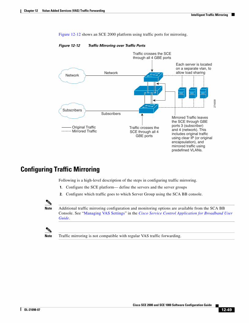
Chapter 12 Value Added Services (VAS) Traffic ForwardingIntelligent Traffic Mirroring
Figure 12-12 shows an SCE 2000 platform using traffic ports for mirroring.
Figure 12-12 Traffic Mirroring over Traffic Ports
Configuring Traffic MirroringFollowing is a high-level description of the steps in configuring traffic mirroring.
1. Configure the SCE platform— define the servers and the server groups
2. Configure which traffic goes to which Server Group using the SCA BB console.
Note Additional traffic mirroring configuration and monitoring options are available from the SCA BB Console. See “Managing VAS Settings” in the Cisco Service Control Application for Broadband User Guide.
Note Traffic mirroring is not compatible with regular VAS traffic forwarding.
Each server is locatedon a separate vlan, toallow load sharing
2740
09
Network
Subscribers
Network
Subscribers
Original TrafficMirrored Traffic
Mirrored Traffic leavesthe SCE through GBEports 3 (subscriber)and 4 (network). Thisincludes original trafficusing clear IP (or originalencapsulation), and mirrored traffic usingpredefined VLANs.
Traffic crosses the SCEthrough all 4 GBE ports
Traffic crosses theSCE through all 4
GBE ports
12-49Cisco SCE 2000 and SCE 1000 Software Configuration Guide
OL-21098-07

Chapter 12 Value Added Services (VAS) Traffic ForwardingIntelligent Traffic Mirroring
Configuration of the traffic mirroring solution is distributed between the SCA BB console and the SCE platform CLI:
• SCE platform CLI configuration:
There are three broad aspects to traffic mirroring configuration in the SCE platform:
– Configuring the VAS traffic link. (See How to Select the Link for VAS Traffic, page 12-19)
Note In a cascaded topology, the VAS traffic link should always be Link 0.
– Configuring the VLAN tag per VAS server. (See How to Configure the VLAN Tag Number for a Specified VAS Server, page 12-21)
– Associating servers with server groups. (See How to Add and Remove Servers, page 12-25)
The health check is not relevant to traffic mirroring, so there is no need to configure anything related to the VAS health check.
• SCA BB console configuration — the traffic mirroring rules, meaning which portion of the subscriber traffic should be mirrored to the VAS servers.
This configuration is defined per package so different subscribers can receive different mirroring service, based on the package they bought.
Monitoring Traffic MirroringUse the same commands to monitor traffic mirroring as for regular VAS functionality. (See Monitoring VAS Traffic Forwarding, page 12-28)
12-50Cisco SCE 2000 and SCE 1000 Software Configuration Guide
OL-21098-07

Chapter 12 Value Added Services (VAS) Traffic ForwardingIntelligent Traffic Mirroring
Traffic Mirroring Sample Configuration Following is a sample illustrating the steps in configuring the SCE 2000 platform for traffic mirroring.
Command Purpose
Step 1 SCE#configure
SCE(config)# interface LineCard 0
Enters LineCard Interface configuration mode
Step 2 SCE(config if)# #VAS-traffic-forwarding traffic-link link-0
Changes the link on which the mirrored packets are sent from link-1 which is the default to link-0.
Step 3 SCE(config if)#VAS-traffic-forwarding VAS server-id 0 VLAN 640SCE(config if)#VAS-traffic-forwarding VAS server-id 1 VLAN 641SCE(config if)#VAS-traffic-forwarding VAS server-id 2 VLAN 642SCE(config if)#VAS-traffic-forwarding VAS server-id 3 VLAN 643
Assign VAS servers 0-3 to VLAN 640-643 respectively.
Step 4 SCE(config if)#VAS-traffic-forwarding VAS server-group 0 server-id 0SCE(config if)#VAS-traffic-forwarding VAS server-group 0 server-id 1SCE(config if)#VAS-traffic-forwarding VAS server-group 1 server-id 2SCE(config if)#VAS-traffic-forwarding VAS server-group 1 server-id 3
Map VAS servers 0-1 and 2-3 to server groups 0 and 1 respectively, allowing server redundancy within each group.
12-51Cisco SCE 2000 and SCE 1000 Software Configuration Guide
OL-21098-07

Chapter 12 Value Added Services (VAS) Traffic ForwardingIntelligent Traffic Mirroring
12-52Cisco SCE 2000 and SCE 1000 Software Configuration Guide
OL-21098-07