Embed Size (px)
Citation preview

■* National Defence Defense nationale Research and Bureau de recherche Development Branch et developpement
TECHNICAL MEMORANDUM 97/203 November 1996
VALIDATION OF
SHIPM07 AND PRECAL WITH A
WARSHIP MODEL
Dann L. Chow — Kevin A. McTaggart
Dm QUÄLET/ msFEmi ÜB 4
Defence Research Establisnment Atlantic
Canada
Centre de Recherches pour la Defense Atlantique
Approved for public release; Distribution Unlimited
19970911 074

DEFENCE RESEARCH ESTABLISHMENT ATLANTIC CENTRE DE RECHERCHES POUR LA DEFENSE ATLANTIQUE
9 GROVE STREET P.O. BOX 10I2 DARTMOUTH, N.S. B2Y 3Z7
9 GROVE STREET TELEPHONE
(902) 426-3IOO
C.P. BOX 1012 DARTMOUTH, N.E. B2Y 3Z7

1*1 National Defence Defense nationale Research and Development Branch
Bureau de recherche et developpement
VALIDATION OF
SHIPM07 AND PRECAL WITH A
WARSHIP MODEL
Dann L. Chow — Kevin A. McTaggart
November 1996
Approved by R.W. Graham: Head/Hydronautics Section
TECHNICAL MEMORANDUM 97/203
Canada
Defence Research Establishment Atlantic
Centre de Recherches pour la Defense Atlantique

Abstract
This technical memorandum describes a validation study of SHIPM07 and PRECAL, two frequency domain codes for predicting ship motions and sea loads in waves. SHIPM07 is a strip theory code while PRECAL is a three-dimensional panel code. Results from the two codes are compared with non-proprietary experimental data for a warship model. In general, SHIPM07 gives good agreement with motions and sea loads, while PRECAL is slightly inferior. The consistently better results for SHIPM07 in the lateral plane are likely due to its careful treatment of appendage and viscous forces. Neglecting rudder autopilot motions does not appear to influence significantly predictions from either code. A proposed approximate method for predicting sectional gyradii leads to satisfactory predictions of torsional moment.
Resume
Cette note technique decrit une etude de validation de SHIPM07 et de PRECAL, deux codes du domaine des frequences pour predire les mouvements des navires et les chargements hydrodynamiques dans les vagues. SHIPM07 est un code de la theorie des bandes alors que PRECAL est un code de facettes tridimensionnel. Les resultats des deux codes sont compares ä des experiences non brevetees avec un modele pour navires de guerre. En general, le SHIPM07 correspond bien aux mouvements et aux chargments hydrodynamiques, alors que le PRECAL est legerement inferieur. Les resultats du SHIPM07 sont toujours meilleurs dans le plan lateral ä cause de la prise en compte detaillee des appendices et des efforts visqueux. L'absense de prise en compte des mouvements du gouvernail ne semble pas influer de fagon importante sur les predictions du SHIPM07 et du PRECAL. On propose une methode approximative de prediction des rayons de giration des sections que permet de predire de fagon satisfaisante le moment de torsion.
n

DREA TM/97/203
VALIDATION OF SHIPMQ7 AND PRECAL WITH A WARSHIP MODEL
by
Dann Chow and Kevin McTaggart
EXECUTIVE SUMMARY
Introduction
SHIPM07, the latest version of DREA's strip theory ship motion program, can now predict sea loads, including forces from appendages. PRECAL, which has been developed by the Coop- erative Research Ships organization, is another tool available to DND for predicting ship motions and sea loads. Because PRECAL is a fully three-dimensional code, it should give more accurate results than the strip theory code SHIPMO, particularly for low L/B hull forms. This technical memorandum compares motion and load predictions for SHIPM07 and PRECAL with exper- imental data for a warship model. Because the experimental data are non-proprietary, DND is able to distribute this validation study to other organizations considering using SHIPM07 or PRECAL. The present validation study was an integral part of the SHIPM07 development process, and helped to ensure proper implementation of the underlying theory.
Principal Results
Both SHIPM07 and PRECAL give generally good motion and sea load predictions for the warship model. As expected, vertical plane predictions are better than lateral plane predictions and motion predictions are better than sea load predictions. Despite the limitations of strip the- ory, SHIPM07 gives better results than PRECAL, particularly for lateral plane motions and sea loads. Problems with PRECAL roll damping predictions required that roll damping coefficients from SHIPM07 be used as input for PRECAL. Torsion predictions differ significantly between SHIPM07 and PRECAL because PRECAL assumes constant metacentric height for all ship sections while SHIPM07 correctly considers the longitudinal variation of roll restoring forces. It appears that neglecting rudder motions does not introduce significant errors to motion and load predictions. A proposed method for approximating sectional roll gyradii gives consistency between motion and load roll inertial properties and leads to satisfactory torsion predictions.
Significance of Results
SHIPM07 motion and sea load predictions appear to be sufficiently accurate for design of naval frigates. PRECAL, which requires significantly greater computational resources because it is fully three-dimensional, gives accuracy similar to SHIPMO in the vertical plane but is less accurate in the lateral plane. The present version of PRECAL does not correctly predict roll damping; thus, the user must provide roll damping coefficients as input. For slender ships such as narrow stern naval frigates, the only advantage of PRECAL relative to SHIPM07 is that it can provide hull pressures.
in

Future Plans
It is recommended that DND adopt SHIPM07 for predictions of motions and sea loads in ship design. If hull hydrodynamic pressures are required or a low L/B hull form is under consideration, then PRECAL should be used. Hopefully, future versions of PRECAL will be able to predict roll damping satisfactorily. The proposed method for approximating sectional roll gyradii will likely be used for predicting torsional loads on DND ships.
IV

Contents
Abstract JJ
Executive Summary üj
Table of Contents v
Notation vj
1 Introduction \
2 SHIPM07 Strip Theory Program 1
3 PRECAL Program Suite 2
4 Description of Model and Experiments 3
5 Ship Input Parameters for SHIPM07 and PRECAL 3
6 Validation Study Results 6
7 Discussion of Results 7 7.1 Ship Motions 7 7.2 Sea Loads 8
8 Conclusions 8
Appendices 10
A SHIPM07 Sample Input File 10
B PRECAL Sample Input Files 14 B.l HYDMES Pre-processor Input File 1 - warship.hin 14 B.2 HYDMES Pre-processor Input File 2 - warship.hul 16 B.3 HYDCAL Input File - warship.cnd 18 B.4 RESCAL Input File - warship.inp 19
C Validation Study Results 20 C.l Ship Motions 20 C.2 Sea Loads 43
References HI

Notation
a wave amplitude
AP aft perpendicular
B beam
CG center of gravity
Fn Froude number
FP forward perpendicular
g gravitational acceleration
Ixx roll moment of inertia for entire vessel
Ixx-i roll moment of inertia of section i (about local CG)
kr proportionality constant for calculating sectional roll gyradii
KG vertical location of centre of gravity (above baseline)
L ship length between perpendiculars
li length of section i
m,i mass of section i
Ns number of ship sections
rxx roll radius of gyration
rxx-i roll radius of gyration of section i (about local CG)
V{ load amplitude for mode i
Zi height of CG of section i above ship CG
ßs incident sea direction (relative to ship speed)
(i motion amplitude for mode i
A wavelength
p water density
uj wave frequency
u>e encounter frequency
A ship mass displacement
VI

1 Introduction
The ability to predict ship responses at sea accurately is a problem of great interest to naval architects. This report describes a validation study of the ship motions and sea loads of a warship model predicted by two codes, SHIPM07 and PRECAL. The warship model was developed by Lloyd et al. [1, 2] and tested at Admiralty Marine Technology Establishment, Haslar. Experiments were conducted in regular waves at two ship speeds and seven headings. SHIPM07 is an updated version of DREA's ship motion code SHIPMO [3], a strip theory program suitable for evaluating seakeeping of slender ships in moderate seas. PRECAL is a suite of programs developed through the Netherlands Ship Model Basin (NSMB) Cooperative Research Ships (CRS) PRECAL Working Group and is based on three-dimensional panel theory. Both programs are designed to predict ship motions in regular waves, and in uni-directional and multi-directional irregular seas.
Validation studies of previous SHIPMO versions have shown that predictions for ship motions are in good agreement with experimental data, whereas predictions for sea loads are generally not as accurate [4, 5]. It was postulated that the new version of SHIPMO could give superior load predictions if all forces acting on the ship were treated consistently for both motion and load calculations. The present validation study was done concurrently with the development of SHIPM07 to ensure correct implementation of load predictions.
This report begins by providing a description of SHIPM07 and PRECAL and their capa- bilities. A brief discussion of their theoretical backgrounds and code designs is also included. A short description of the warship experiments is provided, followed by a discussion of relevant inputs for SHIPM07 and PRECAL. Finally, comparisons of the predictions with the experi- mental data are presented, accompanied by an analysis of the results and conclusions based on this validation study.
2 SHIPM07 Strip Theory Program
SHIPM07 is the newest version of DREA's ship motion program SHIPMO, a strip theory program that is suitable for evaluating seakeeping of slender ships in moderate seas. SHIPMO predicts ship motions for six degrees of freedom, in both regular and irregular waves. From responses for the six basis degrees of freedom, SHIPMO can calculate sea loads, local acceler- ations, slamming, deck wetness, ship-referenced forces, and motion-induced interruptions. The main advantages of SHIPMO relative to many other seakeeping codes are its relatively simple input specification, fast computational time, and robustness.
SHIPMO is a typical frequency domain strip theory code, and is based largely on the theory of Salvesen, Tuck, and Faltinsen [6]. In addition to this linear potential theory basis, SHIPMO includes extensions described by Schmitke [7] to include viscous roll damping and the effects of ship appendages. The program is expected to give reliable results within the limitations of strip theory, that is for slender ships (L/B > 4) operating in moderate sea conditions (e.g. up to sea state 7 for naval frigates) [3].
Strip theory requires the user to divide the ship into a large number of two-dimensional sections in the vertical y — z plane (i.e. a large number of "strips"). The potential flow around each section is determined. Velocity potentials and hydrodynamic coefficients are then calculated for each section and integrated along the ship length to obtain hydrodynamic coefficients for

the entire ship. Using computed hydrodynamic forces, SHIPMO computes motions in regular waves. For lateral plane motions, an iterative process is used to determine amplitude-dependent roll damping and the subsequent ship responses. After motions in regular waves are computed, SHIPMO can compute motions in irregular seas using linear superposition.
SHIPM07 introduces several features that were either not present in the previous versions or have been significantly improved [3]:
1. elimination of irregular frequencies,
2. consistent integration of forces for motion and load predictions,
3. inclusion of all appendage and viscous forces in load predictions,
4. prediction of added resistance in waves.
The resulting code appears to be sufficiently robust for routine engineering computations.
3 PRECAL Program Suite
PRECAL is a suite of programs that predict motions, sea loads, and the pressure distribution on a ship hull in waves. The programs were developed through three CRS Working Groups and are intended to be suitable for most ship types. The three core programs of PRECAL that were used in this validation study are as follows:
• HYDMES: generates the hydrodynamic mesh and calculates the hydrostatic and mass inertia terms.
• HYDCAL: calculates the velocity potentials, source strengths, and flow velocities for the hydrodynamic mesh.
• RESCAL: determines the global ship motion responses and resulting sea loads.
A program to post-process RESCAL results for use in finite element meshes is available but was not required for this study. For further details concerning PRECAL's code design and theory, consult References 8 and 9.
Although similar to SHIPM07, PRECAL predictions are based on three-dimensional panel theory rather than two-dimensional strip theory. For this reason, it was expected that PRECAL predictions for ship loads would demonstrate slightly better agreement with experimental results than SHIPM07.
PRECAL allows the user to choose either the zero-speed Green function or the forward-speed Green function for use in its analysis. In this validation study, the less complicated and more computationally stable [10, 11] zero-speed Green function is used throughout. In addition, the automatic panel generation option that PRECAL offers is also used.
The current CRS-distributed version of PRECAL (version 1.0) still contains several coding problems. Only one of these errors affects this study directly. The roll damping contributed by fin lift forces, eddy damping, and viscous hull effects are not calculated accurately. To circumvent this problem, roll damping coefficients calculated by SHIPMO 7 were used as input for the RESCAL response calculation program.

4 Description of Model and Experiments
The experiments reported by Lloyd et al. are perhaps the most comprehensive set of non- proprietary data for ship motions and sea loads in regular waves. To assist with validation of seakeeping codes, References 1 and 2 include complete descriptions of the warship model and experimental conditions.
The warship model is representative of a typical narrow stern naval destroyer. The model was constructed using four segments that were joined at stations 5, 10, and 13 (SHIPMO convention, described below). Strain gauge dynamometers were attached at the segment joints to measure the loads acting on the ship. Motions were measured with accelerometers.
All tests were conducted in regular waves at a wave steepness (wave height/wavelength) of 1/50 at wave headings of 0, 30, 60, 90, 120, 150, and 180 degrees, where 180 degrees represents head seas. The tests were conducted at nominal Froude numbers of 0.21 and 0.29 based on power in calm water, with actual speeds in waves estimated to be within 10 percent of the nominal values. A full set of experimental results exists for the lower ship speed, but some cases for the higher speed were not completed.
5 Ship Input Parameters for SHIPM07 and PRECAL
It is essential that the input parameters describing the warship model are accurate in order to present a valid comparison between the ship motion and sea load predictions and the exper- imental results. Among the most vital of these parameters are the mass distribution and the sectional roll properties. Sample input files are presented in Appendix A for SHIPMO and in Appendix B for PRECAL. The PRECAL computations used 160 panels on half the hull surface.
The sectional mass distribution of the warship model is provided by Lloyd et al. (Refer- ence 1, Table II). Although 21 equally-spaced stations are used in References 1 and 2 and in both prediction codes, the station numbering convention varies. Lloyd et al. use stations 1 to 21, with 1 being the FP and 21 being the AP. SHIPM07 uses stations 0 to 20, with 0 being the FP and 20 being the AP. PRECAL uses stations 0 to 10, and reverses the order by making 0 the AP and 10 the FP. For the current validation study, the sea load analysis is performed at stations 5, 10, and 13 according to the SHIPM07 convention.
Sectional masses are assumed to be uniformly distributed between mid-stations (e.g.. stations 0.5 and 1.5) except at the bow and stern. The mass for station 0 is assumed to be evenly distributed between stations 0 and 0.5, while the mass for station 20 is assumed to be evenly distributed between stations 19.5 and 20. Provisions for bow and stern overhang masses are available in both SHIPM07 and PRECAL but are not required for the warship model. The resulting sectional mass distribution is shown in Figure 1.
To verify the input sectional mass distribution of Figure 1, masses were evaluated for each of the four warship segments and compared with actual segment masses given in Reference 1. Figure 2 indicates that the computed segment masses are in excellent agreement with the actual values.
For each ship section on a given model segment, the section KG value is assumed to be equal to the segment KG value. For a section that spans two segments, the section KG value is a weighted average. Figure 3 shows the resulting section KG values for computations.

50
40
Sectional Mass
(kg)
30
20
10
i I I I i i i i i i i i i i i i i i
6 8 10 12 14 16 18 20
Station Number (0 is FP, 20 is AP)
Figure 1: Input Sectional Mass Distribution for Warship Model
150
100
Segment Mass
(kg)
50
i i i j i_
SHIPM07 masses
- - Model masses
8SHIPM07 LCG
<g> Model LCG
i I i i i i
2 4 6 8 10 12 14 16 18 20
Station Number (0 is FP, 20 is AP)
Figure 2: Segment Mass Distribution for Warship Model

300 (^
200
Sectional KG (mm)
100
4 6 8 10 12 14 16
Station Number (0 is FP, 20 is AP)
i l i
18 20
Figure 3: Assumed Sectional KG Values for Computations
The warship roll gyradius based on properties of the four model segments is equal to 182 mm; however, Lloyd et al. report that the actual dry ship gyradius based on the model roll natural frequency is 198 mm. They indicate that the value of 182 mm based on the four model segments is likely incorrect because of inaccuracies in the measured gyradii of the segments. Using an input dry gyradius of 198 mm, SHIPM07 calculates the roll natural frequency at zero speed to be 2.29 rad/s, which is considered to be acceptably close to the value of 2.37 rad/s reported in Reference 1.
For predicting torsional loads, SHIPM07 and PRECAL required input sectional roll gyradii. The input sectional gyradii must be consistent with the ship roll gyradius used for motion computations. Given the absence of measured sectional gyradii, the following procedure was used to obtain estimates of sectional gyradii that were consistent with the ship gyradius:
1. Calculate roll moment of inertia Ixx for the entire vessel using the roll radius of gyration rxx value of 198 mm reported for the entire ship:
= Ar (5.1)
2. Assume that the local roll gyradius rIX_j about the sectional CG is directly proportional to the square root of the mass per unit length mi/li of the section. This assumption is based on the premise that the mass for each section can be modelled as a circular cylinder, with density being constant along the entire ship length but with a different radius for each ship section. A single proportionality constant kT is applicable along the length of the ship.
TTT—?. — Kr (5.2)

3. Solve for the proportionality constant kr. The following equation gives the total roll inertia of the ship:
Ns
= £ U i=l
rrij
k + Zj m (5.3)
where Ns is the number of ship sections and Z{ is the sectional CG elevation relative to the ship CG. Using the above equation, the constant kr is solved as follows:
\
Ns 'II 2-<i=l miZ;
srNs ™1 (5.4)
4. Compute the sectional roll gyradii using Equation (5.2).
This method provides reasonable estimates of sectional roll gyradii which are consistent with the ship inertia properties.
As mentioned earlier, the current version of PRECAL has problems computing roll damping; thus, roll damping coefficient based on SHIPM07 calculations were used as input to PRECAL. For each combination of ship speed and heading, SHIPM07 roll damping coefficients exhibited relatively little variation with wave frequency. Because of the importance of roll damping during roll resonance, the SHIPM07 roll damping at a wave encounter frequency corresponding to the ship roll natural frequency was considered suitable for all wave frequencies. Further examination of SHIPM07 roll damping coefficients indicated that roll damping showed little variation with ship heading and could be modelled as a function of only ship speed. The high ship speeds and low roll motion amplitudes of the warship model cause lift forces to dominate roll damping, with the resulting dependence on ship speed. The PRECAL computations use roll damping coefficients of 0.19 and 0.24 for the Froude numbers of 0.21 and 0.29 respectively.
Although the warship model was steered by autopilot during the experiments, it was assumed that rudder deflections were zero in the SHIPM07 and PRECAL runs because of insufficient data regarding the autopilot properties.
6 Validation Study Results
This section presents the comparison plots between numerical predictions and the experi- mental results for the warship model. Predictions from SHIPM07 and PRECAL are shown for every test case, whereas experimental results are shown whenever available. Non-dimensionalized bending moments and shear forces have been multiplied by a factor of 100, except for torsional moment which is multiplied by 1000, as is done in References 1 and 2.
Comparison plots are presented in Appendix C.l for ship motions and in Appendix C.2 for sea loads. The order of presentation is shown in Table 1. For each speed/heading combination, the following motions and loads were considered: roll, heave, pitch, yaw, vertical bending moment, horizontal bending moment, torsional moment, and vertical shear force. All loads are analyzed at three locations: stations 5, 10 and 13 (SHIPMO convention). Motions and loads which were deemed insignificant by Lloyd et al., such as the roll motion in head and following seas, are not presented. Horizontal shear force, which is significant for oblique seas, was not considered by
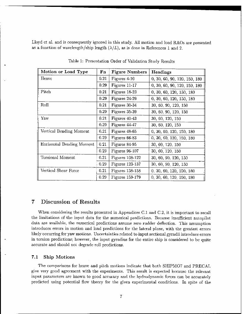
Lloyd et al. and is consequently ignored in this study. All motion and load RAOs are presented as a function of wavelength/ship length (X/L), as is done in References 1 and 2.
Table 1: Presentation Order of Validation Study Results
Motion or Load Type Fn Figure Numbers Headings
. Heave 0.21 Figures 4-10 0, 30, 60, 90, 120, 150, 180
0.29 Figures 11-17 0, 30, 60, 90, 120, 150, 180
Pitch 0.21 Figures 18-23 0, 30, 60, 120, 150, 180
0.29 Figures 24-29 0, 30, 60, 120, 150, 180
Roll 0.21 Figures 30-34 30, 60, 90, 120, 150
0.29 Figures 35-39 30, 60, 90, 120, 150
Yaw 0.21 Figures 40-43 30, 60, 120, 150
0.29 Figures 44-47 30, 60, 120, 150
Vertical Bending Moment 0.21 Figures 48-65 0, 30, 60, 120, 150, 180
0.29 Figures 66-83 0, 30, 60, 120, 150, 180
Horizontal Bending Moment 0.21 Figures 84-95 30, 60, 120, 150
0.29 Figures 96-107 30, 60, 120, 150
Torsional Moment 0.21 Figures 108-122 30, 60, 90, 120, 150
0.29 Figures 123-137 30, 60, 90, 120, 150
Vertical Shear Force 0.21 Figures 138-158 0, 30, 60, 120, 150, 180
0.29 Figures 159-179 0, 30, 60, 120, 150, 180
7 Discussion of Results
When considering the results presented in Appendices C.l and C.2, it is important to recall the limitations of the input data for the numerical predictions. Because insufficient autopilot data are available, the numerical predictions assume zero rudder deflection. This assumption introduces errors in motion and load predictions for the lateral plane, with the greatest errors likely occurring for yaw motions. Uncertainties related to input sectional gyradii introduce errors in torsion predictions; however, the input gyradius for the entire ship is considered to be quite accurate and should not degrade roll predictions.
7.1 Ship Motions
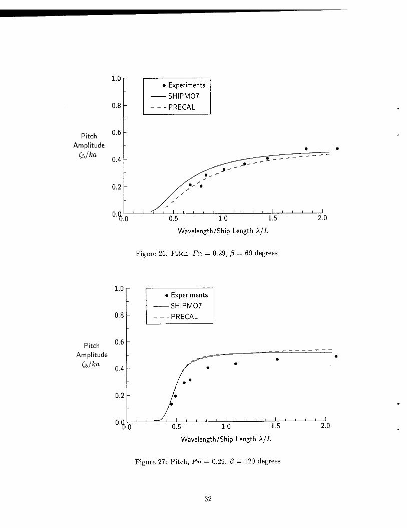
The comparisons for heave and pitch motions indicate that both SHIPM07 and PRECAL give very good agreement with the experiments. This result is expected because the relevant input parameters are known to good accuracy and the hydrodynamic forces can be accurately predicted using potential flow theory for the given experimental conditions. In spite of the
7

limitations of strip theory, SHIPM07 predictions do not appear to deteriorate at the higher ship speed.
For roll motions, SHIPM07 gives good predictions even though rudder motions are neglected. PRECAL has a tendency to underpredict roll motions. The superior performance of SHIPM07 is likely because great development effort has been devoted to prediction of lateral plane forces, including appendage and viscous forces.
For yaw motions, experimental data are available only for a Froude number of 0.21 at head- ings of 30 and 60 degrees. SHIPM07 gives good agreement with the experiments even though the autopilot is not modelled. PRECAL appears to underpredict the yaw motions. In Figure 44, PRECAL yaw predictions exhibit an anomaly at X/L « 0.4 due to a very low encounter fre- quency. SHIPM07 uses approximations based on other wavelengths to avoid such anomalies at low encounter frequencies.
7.2 Sea Loads
For vertical bending moment, SHIPM07 and PRECAL give very good agreement with the experiments, with SHIPM07 giving somewhat more consistent results. The most striking con- trasts between SHIPM07 and PRECAL predictions occur at a heading of 60 degrees for both Froude numbers, with SHIPM07 giving good predictions while PRECAL significantly under- predicts bending moments.
Even though the autopilot is not modelled, SHIPM07 gives good results for horizontal bending moment while PRECAL tends to underpredict. For torsion, SHIPM07 gives acceptable results, suggesting that the method described in Section 5 gives reasonable values for sectional gyradii. The poor torsion predictions by PRECAL are attributed to its assumption that the metacentric height of each ship section is equal to the ship metacentric height. In contrast, SHIPM07 correctly considers the variation of sectional metacentric heights along the ship length.
Experimental data for vertical shear are available only for stations 5 and 13 in head seas at a Froude number of 0.21. Based on these two cases, SHIPM07 appears to give good results while PRECAL underpredicts vertical shear. At a Froude number of 0.29 and heading of 60 degrees, SHIPMO predictions in Figures 166 and 167 are unexpectedly high at short wavelengths, while PRECAL predictions appear to be more reasonable. Unfortunately, there are no experimental data available for comparison. The cause of this result is unknown given that the encounter frequency appears to be sufficiently high for good predictions from SHIPM07 and PRECAL.
8 Conclusions
Both SHIPM07 and PRECAL give generally good motion and sea load predictions for the warship model. As expected, vertical plane predictions tend to be better than lateral plane predictions and motion predictions tend to be better than sea load predictions. Despite the limitations of strip theory, SHIPM07 gives better results than PRECAL, particularly for lateral plane motions and sea loads. Problems with PRECAL roll damping predictions required that roll damping coefficients from SHIPM07 be used as input for PRECAL. It appears that the neglect of rudder motions does not introduce significant errors to motion and load predictions. A proposed method for approximating sectional roll gyradii gives consistency between motion and load roll inertial properties and leads to satisfactory torsion predictions from SHIPM07. Poor

torsion predictions from PRECAL are likely due to its assumption that sectional metacentric height is constant along the ship length.

A SHIPM07 Sample Input File
Lloyd Warship, offsets, inertia based on mass distribution < Title
METRIC METRIC FRESH SPEEDCOR NOSWELLCOR MODAMP OUTPPR < Options
warship.ppr < Post-processing file name
LOAD NORAW < Options 2.2 6.0 0.1 < Wave frequency min, max, increment
WRITEHY B0UND2D LATLONG HVCOR < Hydrodynamic coefficient flags
warship.hy < Hydrodynamic coefficient file
1. 16. 0.75 < Encounter frequency min, max, increment
REGULAR < Wave spectrum 7 0.0 < Number of sea directions, spreading angle
0. 30. 60. 90. 120. 150. 180. < Sea directions 1 < Number of seaways
0.02 < Wave steepness
2 3.17 4.38 < Number of speeds, speed array
6.157 0.283 1.355 < Ship length, KG, pitch RG
GMC0MP DRYROLLRG < GM and roll RG flags
0.198 < Dry roll RG OFFSETS < Hull form definition flag
21 21 1. 1. < Stations, scaling factors
0 < Offset data
3 0.000 0.008 0.009 0.204 0.207 0.233
1 11
0.000 0.010 0.017 0.024 0.029 0.033 0.037 0.041 0.045 0.049 0.053 0.000 0.000 0.026 0.052 0.078 0.103 0.129 0.155 0.181 0.207 0.233
2 11
0.000 0.014 0.034 0.048 0.059 0.068 0.075 0.081 0.087 0.093 0.100 0.000 0.000 0.026 0.052 0.078 0.103 0.129 0.155 0.181 0.207 0.233
3 11
0.000 0.017 0.053 0.076 0.093 0.105 0.114 0.123 0.131 0.139 0.147 0.000 0.000 0.026 0.052 0.078 0.103 0.129 0.155 0.181 0.207 0.233
4 11
0.000 0.019 0.072 0.106 0.127 0.143 0.155 0.166 0.175 0.184 0.192 0.000 0.000 0.026 0.052 0.078 0.103 0.129 0.155 0.181 0.207 0.233
5 11
0.000 0.021 0.098 0.138 0.163 0.182 0.196 0.207 0.217 0.225 0.233 0.000 0.000 0.026 0.052 0.078 0.103 0.129 0.155 0.181 0.207 0.233
6 11
0.000 0.023 0.123 0.173 0.201 0.220 0.234 0.245 0.254 0.261 0.267 0.000 0.000 0.026 0.052 0.078 0.103 0.129 0.155 0.181 0.207 0.233
10

7 11
0.000 0.024 0.154 0.209 0.238 0.257 0.269 0.278 0.285 0.289 0.293 0.000 0.000 0.026 0.052 0.078 0.103 0.129 0.155 0.181 0.207 0.233
8 11
0.000 0.025 0.182 0.239 0.267 0.285 0.295 0.302 0.307 0.310 0.312 0.000 0.000 0.026 0.052 0.078 0.103 0.129 0.155 0.181 0.207 0.233
9 11
0.000 0.025 0.200 0.259 0.286 0.301 0.310 0.316 0.320 0.322 0.323 0.000 0.000 0.026 0.052 0.078 0.103 0.129 0.155 0.181 0.207 0 233
10 11
0.000 0.025 0.208 0.238 0.295 0.309 0.317 0.322 0.325 0.327 0.328 0.000 0.000 0.026 0.052 0.078 0.103 0.129 0.155 0.181 0 207 0 233
11 11
0.000 0.024 0.190 0.258 0.289 0.306 0.316 0.322 0.325 0.327 0.328 0.000 0.000 0.026 0.052 0.078 0.103 0.129 0.155 0.181 0.207 0 233
12 11
0.000 0.024 0.157 0.237 0.274 0.296 0.309 0.317 0.321 0.326 0.327 0.000 0.000 0.026 0.052 0.078 0.103 0.129 0.155 0.181 0 207 0 233
13 11
0.000 0.023 0.101 0.194 0.245 0.276 0.295 0.308 0.315 0.319 0.321 0.000 0.000 0.026 0.052 0.078 0.103 0.129 0.155 0.181 0.207 0 233
14 11
0.000 0.021 0.056 0.125 0.195 0.242 0.272 0.291 0.303 0.310 0.313 0.000 0.000 0.026 0.052 0.078 0.103 0.129 0.155 0.181 0.207 0 233
15 11
0.000 0.020 0.035 0.067 0.127 0.192 0.237 0.266 0.284 0.294 0.299 0.000 0.000 0.026 0.052 0.078 0.103 0.129 0.155 0.181 0.207 0 233
16 10
0.000 0.021 0.034 0.063 0.126 0.193 0.236 0.260 0.273 0.281 0.005 0.026 0.052 0.078 0.103 0.129 0.155 0.181 0.207 0.233
17 8
0.000 0.027 0.058 0.132 0.197 0.230 0.246 0.256 0.059 0.078 0.103 0.129 0.155 0.181 0.207 0.233
18 7
0.000 0.015 0.057 0.149 0.193 0.214 0.225 0.100 0.103 0.129 0.155 0.181 0.207 0.233
11

19 5
0.000 0.081 0.151 0.173 0.181 0.134 0.155 0.181 0.207 0.233
20 3
0.000 0.049 0.083 0.204 0.207 0.233
DISP 0.4022 3.108 3 5 10 13 .00230 .00715 .02817 .01442 0.296 0.292 0.267 0.083 0.206 0.148
.00991
.03786
.00956 0.296 0.286 0.267 0.122 0.239 0.120
.03864
.01094 0.296 0.292 0.267 0.104 0.242 0.129
0.0 0.0 0.0 0.0 0.0 0.0 0.0 0.0 0.0 0.0 0 0. 0. 5 7 7 7 9 8
< < <--■
< .01276 .03321 .00795 0.296 0.280 0.267 0.139 0.224 0.110
- Control flag for load waterline - Displacement, LCG - Number of stations for sea loads Station for sea loads .01826 .02326 .01806 .01496
02464 .01872 .03529 .00250 0.296 0.280 0.267 0.166 0.231 0.087
.03364
0.294 0.274
0.188 0.226
0.292 0.267
0.165 0.193
0.292 0.267
0.150 0.168
< Sectional tonnages
< Sectional KG values
< Sectional RRG values
8 073 7.500 0.251 0.095 0.024 500 8.093 0.267 0.078 0.024
9 801 9.356 0.276 0.069 0.024
< Bow mass distribution < Stern mass distribution <— <— <—
Number of seakeeping positions Number of bilge keel pairs Stations for bilge keel pairs
10.500 0.276 0.069 0.024 11.016 0.277 0.068 0.024
10 11 10.029 10.500 12 12 11.702 12.316 0.270 0.075 0.024 13 14 12.949 13.500 18 19
0. 0. 0. 0.
13.500 0.258 0 13.810 0.243 0
.0.07 0.924
.5 0.10 0.13 0
088 0.024 104 0.024
0 0 4 17.0 0.15 0 17.0 0.07 0 18.8 0.17 0
0. 0. 0 127
. 0. 0.134 0.098 0.0 1
10 0.100 0.021 0.021 0. 09 0.100 0.021 0.021 0. 15 0.142 0.034 0.034 0.
18.8 0.02 0.11 0.128 0.034 0.034 0.
Skeg station, breadth, length Rudder Rudder roll gains
< Rudder yaw gains Number of pairs of stationary foils 107.0 1. < Outboard arm -47.0 1. < Inboard arm 100.0 1. < Outboard arm -60.0 1. < Inboard arm
12

FIN < Stabilization control flag 4 < Number of fin pairs
8.4 0.28 0.1 0.05 0.097 0.097 0. -43.5 1. < Fin pair 1 9.6 0.28 0.1 0.05 0.097 0.097 0. -43.5 1. < Fin pair 2 11.3 0.28 0.1 0.05 0.097 0.097 0. -43.5 1. < Fin pair 3 12.6 0.28 0.1 0.05 0.097 0.097 0. -43.5 1. < Fin pair 4 0. 0. 0. 0. 0. 0. < Stabilizing fin roll gains
13

B PRECAL Sample Input Files
B.l HYDMES Pre-processor Input File 1 - warship.hin
AUTOMATIC FACET GENERATION
Lloyd Warship Model
MONOHULL
OPTION
OCAL
OINP
OOUT
OMAS
ENDOPT
CONSTS
CDEN 1.000
CACC 9.80665
ENDCON
SHIPDS SDIM 6.157 6.157
SGMS 15.511 0.027
SSYM Y=0
ENDSHI
# # Mass Distribution Data
SHIPM07/PRECAL VALIDATION STUDY (June, 1997)
0.653 0.203 -0.007
# DM
MASSDI
0.00230
0.00715
0.00991 0.01276
0.01826
0.02326 0.01806
0.01496
0.02817
0.03864
0.03786 0.03321
0.03529
0.03364 0.02464
0.01872
0.01442
0.01094
0.00956
0.00795
0.00250
ENDMAS
3.
2.
2.
2.
1.
XM
.07850
.77065
.46280
.15495
.84710
1.53925
1.23140
0.92355
0.61570
0.30785
0.00000
-0.30785 -0.61570
-0.92355 -1.23140
-1.53925
-1.84710
-2.15495
-2.46280
-2.77065
-3.07850
YM
0.00000
0.00000
0.00000
0.00000
0.00000
0.00000 0.00000
0.00000 0.00000
0.00000
0.00000 0.00000
0.00000
0.00000
0.00000
0.00000
0.00000
0.00000
0.00000 0.00000
0.00000
ZM
0.09300
0.09300
0.09300
0.09300
0.09300
0.09100
0.08900
0.08900
0.08900
0.08900
0.08300
0.07700 0.07700
0.07100
0.06400
0.06400
0.06400
0.06400
0.06400 0.06400
0.06400
Ixx
0.00002
0.00008
0.00015
0.00025
0.00050
0.00082
0.00049 0.00034
0.00120
0.00226
0.00217 0.00167
0.00188
0.00171 0.00092
0.00053
0.00031
0.00018
0.00014
0.00010
0.00002
iyy
0.00000
0.00000
0.00000
0.00000
0.00000
0.00000 0.00000
0.00000
0.00000
0.00000
0.00000
0.00000
0.00000
0.00000
0.00000
0.00000
0.00000
0.00000
0.00000 0.00000
0.00000
Izz
0.00000
0.00000
0.00000
0.00000
0.00000
0.00000
0.00000
0.00000
0.00000
0.00000
0.00000 0.00000
0.00000
0.00000
0.00000
0.00000
0.00000
0.00000
0.00000
0.00000
0.00000
14

AFTEND TOTFAC 0.5 1.0 80 ENDTOT ENDAFT FOREND TOTFAC 0.5 1.0 80 ENDTOT ENDFOR ENDFIL
15

B.2 HYDMES Pre-processor Input File 2 - warship.hul
Lloyd Warship Model 6.157 0.653 21
0.0 4 0.000 0.0245 0.049 0.083 0.204 0.2055 0.207 0.233 0.5 5
0.000 0.081 0.151 0.173 0. 0.134 0.155 0.181 0.207 0.
1.0 7 0.000 0.015 0.057 0.149 0. 0.100 0.103 0.129 0.155 0. 1.5 8 0.000 0.027 0.058 0.132 0. 0.059 0.078 0.103 0.129 0. 2.0 10
0.000 0.021 0.034 0.063 0. 0.005 0.026 0.052 0.078 0. 2.5 11 0.000 0.020 0.035 0.067 0. 0.000 0.000 0.026 0.052 0. 3.0 11
0.000 0.021 0.056 0.125 0. 0.000 0.000 0.026 0.052 0. 3.5 11
0.000 0.023 0.101 0.194 0. 0.000 0.000 0.026 0.052 0. 4.0 11
0.000 0.024 0.157 0.237 0. 0.000 0.000 0.026 0.052 0. 4.5 11 0.000 0.024 0.190 0.258 0. 0.000 0.000 0.026 0.052 0. 5.0 11
0.000 0.025 0.208 0.238 0. 0.000 0.000 0.026 0.052 0. 5.5 11 0.000 0.02'5 0.200 0.259 0, 0.000 0.000 0.026 0.052 0. 6.0 11 0.000 0.025 0.182 0.239 0 0.000 0.000 0.026 0.052 0 6.5 11
0.000 0.024 0.154 0.209 0 0.000 0.000 0.026 0.052 0 7.0 11
0.000 0.023 0.123 0.173 0 0.000 0.000 0.026 0.052 0
181 233
193 0.214 0.225 181 0.207 0.233
197 0.230 0.246 0. 155 0.181 0.207 0,
126 0.193 0.236 0. 103 0.129 0.155 0.
127 0.192 0.237 0. 078 0.103 0.129 0.
195 0.242 0.272 0. 078 0.103 0.129 0.
245 0.276 0.295 0. 078 0.103 0.129 0.
274 0.296 0.309 0. 078 0.103 0.129 0,
289 0.306 0.316 0, 078 0.103 0.129 0
295 0.309 0.317 0 078 0.103 0.129 0
286 0.301 0.310 0 ,078 0.103 0.129 0
,267 0.285 0.295 0 ,078 0.103 0.129 0
.238 0.257 0.269 0
.078 0.103 0.129 0
.201 0.220 0.234 0
.078 0.103 0.129 0
256 233
,260 0.273 0.281 ,181 0.207 0.233
.266 0.284 0.294 0.299 ,155 0.181 0.207 0.233
,291 0.303 0.310 0.313 ,155 0.181 0.207 0.233
.308 0.315 0.319 0.321
.155 0.181 0.207 0.233
.317 0.321 0.326 0.327
.155 0.181 0.207 0.233
.322 0.325 0.327 0.328
.155 0.181 0.207 0.233
.322 0.325 0.327 0.328
.155 0.181 0.207 0.233
.316 0.320 0.322 0.323
.155 0.181 0.207 0.233
.302 0.307 0.310 0.312
.155 0.181 0.207 0.233
.278 0.285 0.289 0.293 155 0.181 0.207 0.233
245 0.254 0.261 0.267 155 0.181 0.207 0.233
16

7.5 11 0.000 0 0.000 0 8.0 11
0.000 0 0.000 0 8.5 11 0.000 0 0.000 0, 9.0 11
0.000 0, 0.000 0. 9.5 11
0.000 0. 0.000 0. 10.0 3 0.000 0. 0.204 0.
021 0.098 0.138 0.163 0.182 0.196 0. 000 0.026 0.052 0.078 0.103 0.129 0.
019 0.072 0.106 0.127 0.143 0.155 0. 000 0.026 0.052 0.078 0.103 0.129 0.
017 0.053 0.076 0.093 0.105 0.114 0. 000 0.026 0.052 0.078 0.103 0.129 0.
014 0.034 0.048 0.059 0.068 0.075 0. 000 0.026 0.052 0.078 0.103 0.129 0.
010 0.017 0.024 0.029 0.033 0.037 0. 000 0.026 0.052 0.078 0.103 0.129 0.
008 0.009 207 0.233
207 0.217 0.225 0.233 155 0.181 0.207 0.233
166 0.175 0.184 0.192 155 0.181 0.207 0.233
123 0.131 0.139 0.147 155 0.181 0.207 0.233
081 0.087 0.093 0.100 155 0.181 0.207 0.233
041 0.045 0.049 0.053 155 0.181 0.207 0.233
17

B.3 HYDCAL Input File - warship.cnd
HYDCAL RUN AT FR = 0.21, May 1997 Lloyd Warship Model MONDHULL OPTION OKTS OFSP ENDOPT CONDNS SPED 3.17 HEAD 0 30 60 90 120 150 180.0 FREQ 2.20 2.40 2.60 2.80 3.00
3.20 3.40 3.60 3.80 4.00 4.20 4.40 4.60 4.80 5.00
ENDCON FSPANS 2 ENDFSP ENDFIL
18

B.4 RESCAL Input File - warship.inp
RESCAL: FR = 0.21, ROLL DAMPING =0.19 FROM SHIPMO (June 1997) Lloyd Warship Model M0N0HULL # OPTION OMOT OPRE OLOA ENDOPT # ROLLIN DAMP 0.190 ENDROL # # LOAD POSITION - Long, loads are calculated at SHIPM07 stations 5.0, # 10.0, 13.0 (PRECAL convention - 0.0 at AP, 1.0 at FP) LOPOSN LONGI 0.750 0.500 0.350 ENDLOP # ENDFIL
19

C Validation Study Results
C.l Ship Motions
20

2.0
1.5
SHIPM07
PRECAL
Heave Amplitude 1.0 -
Ca/a
0.5
■% 0.5 1.0 1.5
Wavelength/Ship Length X/L
2.0
Figure 4: Heave, Fn = 0.21, ß = 0 degrees
2.0 r
1.5
SH1PM07
PRECAL
Heave Amplitude 1.0
Cs/a
0.5 1.0 1.5
Wavelength/Ship Length X/L
2.0
Figure 5: Heave, Fn = 0.21, ß = 30 degrees
21

2.0
1.5 -
SHIPM07
PRECAL
Heave Amplitude 1.0
Cs/a
0.5
n 0.5 1.0 1.5
Wavelength/Ship Length X/L
Figure 6: Heave, Fn = 0.21, ß = 60 degrees
2.0
1.5
Experiments
SHIPM07
PRECAL
Heave Amplitude 1.0
Cs/a
0.5
■%(
j i i i L i I l l I I I 1 1 1 L_
0.5 1.0 1.5
Wavelength/Ship Length X/L
2.0
Figure 7: Heave, Fn = 0.21, ß = 90 degrees
22

2.0
1.5
Experiments
SHIPM07
PRECAL
Heave Amplitude 1.0
0.5 1.0 1.5
Wavelength/Ship Length X/L
2.0
Figure 8: Heave, Fn = 0.21, ß = 120 degrees
2.0
1.5
• Experiments
-SHIPM07
-PRECAL
Heave Amplitude 1.0
Cs/a
0.5 -
0. 0.5 1.0 1.5
Wavelength/Ship Length X/L
2.0
Figure 9: Heave, Fn = 0.21, ß = 150 degrees
23

2.0
1.5
• Experiments
-SHIPM07
-PRECAL
Heave Amplitude 1.0
C3/a
0.5
0. % 0.5 1.0 1.5
Wavelength/Ship Length X/L
Figure 10: Heave, Fn = 0.21, ß = 180 degrees
2.0
1.5
Heave Amplitude 1.0
Ca/a
SHIPM07
PRECAL
Wavelength/Ship Length X/L
Figure 11: Heave, Fn = 0.29, ß = 0 degrees
24

2.0
1.5
SHIPM07
PRECAL
Heave Amplitude 1.0
0.5 -
0.5 1.0 1.5
Wavelength/Ship Length X/L
2.0
Figure 12: Heave, Fn = 0.29, ß = 30 degrees
2.0
1.5
SHIPM07
-PRECAL
Heave Amplitude 1.0
0.5 1.0 1.5
Wavelength/Ship Length X/L
2.0
Figure 13: Heave, Fn = 0.29, ß = 60 degrees
25

2.0 r
1.5
Heave Amplitude 1.0
Ca/a
0.5
0.
• Experiments
-SHIPM07
■ -PRECAL
V _i i i i_ i i i i i i i i i i i i i i i_
0.5 1.0 1.5
Wavelength/Ship Length X/L
2.0
Figure 14: Heave, Fn = 0.29, ß = 90 degrees
2.0
1.5
Heave Amplitude 1.0
Ca/o
0.5
Experiments
SHIPM07
- -PRECAL
% i i i i i l
U'U.0 0.5 1.0 1.5 2.0
Wavelength/Ship Length X/L
Figure 15: Heave, Fn = 0.29, ß = 120 degrees
26

2.0
1.5
Heave Amplitude 1.0
Cs/a
SHIPM07
PRECAL
0.5 1.0 1.5
Wavelength/Ship Length X/L
2.0
Figure 16: Heave, Fn = 0.29, ß = 150 degrees
2.0
1.5 -
Experiments
SHIPM07
PRECAL
Heave Amplitude 1.0
Ca/a
0.5 1.0 1.5
Wavelength/Ship Length X/L
2.0
Figure 17: Heave, Fn = 0.29, ß = 180 degrees
27

Pitch Amplitude
(5/ka
1.0 r
0.8
0.6
0.4
0.2
•%(
Experiments
SHIPM07
PRECAL
^ i i i i i i i i i i I i i_
0.5 1.0 1.5
Wavelength/Ship Length X/L
2.0
Figure 18: Pitch, Fn = 0.21, ß = 0 degrees
Pitch Amplitude
CsAa
1.0
0.8
0.6
• Experiments
-SHIPM07
-PRECAL
0.5 1.0 1.5
Wavelength/Ship Length X/L
Figure 19: Pitch, Fn = 0.21, ß = 30 degrees
28

Pitch Amplitude
(s/ka
1.0
0.8
0.6
0.4
0.2
0. %
• Experiments
-SHIPM07
PRECAL
0.5 1.0 1.5
Wavelength/Ship Length X/L
2.0
Figure 20: Pitch, Fn = 0.21, ß = 60 degrees
1.0
0.8
• Experiments
-SHIPM07
-PRECAL
Pitch Amplitude
C,s/kn
0.6
0.4
0.2 -
0. % 0.5 1.0 1.5
Wavelength/Ship Length X/L
2.0
Figure 21: Pitch, Fn = 0.21, ß = 120 degrees
29

1.0 r
0.8
• Experiments
-SHIPM07
■ -PRECAL
Pitch Amplitude
(5/ka
0.6
0.4
0.2
0. V i i i i I i i i i L
0.5 1.0 1.5
Wavelength/Ship Length X/L
2.0
Figure 22: Pitch, Fn = 0.21, ß = 150 degrees
Pitch Amplitude
(b/ka
1.0 r
0.8
0.6
0.4
0.2
0. % .0
• Experiments
-SHIPM07
■ -PRECAL
i i l I l L.
0.5 1.0 1.5
Wavelength/Ship Length X/L
2.0
Figure 23: Pitch, Fn = 0.21, ß = 180 degrees
30

Pitch Amplitude
(5/ka
1.0
0.8
0.6 -
0.4 -
0.2 -
0. 4.
SHIPM07
PRECAL
- ^^^T'
s— y y^ y / y / y / y
Xy //
1 H '!>-' 1 1 1 1 -i 1 i i i i 1 i i i i
0.5 1.0 1.5
Wavelength/Ship Length X/L
J 2.0
Figure 24: Pitch, Fn = 0.29, ß = 0 degrees
Pitch Amplitude
Cs/ka
1.0 r
0.8 -
0.6
0.4
0.2
■%
• Experiments
SHIPM07
- PRECAL
•
— ^^*~-*~\^ -"
^*-^ " • >r s
S^ S
- /?* /y /y - /y
// . /» • /y
- y»«
, H rr i i i i 1 i i i i 1 i i i i l
0.5 1.0 1.5
Wavelength/Ship Length X/L
2.0
Figure 25: Pitch, Fn = 0.29, ß = 30 degrees
31
1.0
0.8
• Experiments
-SHIPM07
■ -PRECAL
Pitch Amplitude
(s/ka
0.6
0.4
0.2
'•% 0.5 1.0 1.5
Wavelength/Ship Length X/L
Figure 26: Pitch, Fn = 0.29, ß = 60 degrees
1.0
0.8
• Experiments
-SHIPM07
PRECAL
Pitch Amplitude
(5/ka
0.6
0.4
0.2
n Wavelength/Ship Length X/L
Figure 27: Pitch, Fn = 0.29, ß = 120 degrees
32

1.0
Pitch Amplitude
(s/ka
-SHIPM07
-PRECAL
0.5 1.0 1.5
Wavelength/Ship Length X/L
2.0
Figure 28: Pitch, Fn = 0.29, ß = 150 degrees
Pitch Amplitude
(s/ka
1.0
0.8
0.6
0.4
0.2
Experiments
SHIPM07
PRECAL
°Y Wavelength/Ship Length X/L
Figure 29: Pitch, Fn = 0.29, ß = 180 degrees
33

4r • Experiments
-SHIPM07
• -PRECAL
Roll Amplitude 2
V 0.5 1.0 1.5
Wavelength/Ship Length X/L
Figure 30: Roll, Fn = 0.21, ß = 30 degrees
Roll Amplitude 2
(i/ka
• Experiments
— SHIPM07
- -PRECAL
Wavelength/Ship Length X/L
Figure 31: Roll, Fn = 0.21, ß = 60 degrees
34

Roll Amplitude 2
Qi/ka
• Experiments
-SHIPM07
- -PRECAL
0.5 1.0 1.5
Wavelength/Ship Length X/L
2.0
Figure 32: Roll, Fn = 0.21, ß = 90 degrees
Roll Amplitude 2
(4/ka
%
• Experiments - SHIPM07
PRECAL
-
^~-—"• - " "
^^ * — " " " ^^* - ~~ ~~
s^*-*' " 1 -i^\ 1 1 1 1 1 1 1 1 > 1 1 1 1 1 1 1
0.5 1.0 1.5
Wavelength/Ship Length X/L
2.0
Figure 33: Roll, Fn = 0.21, ß = 120 degrees
35

4r • Experiments
-SHIPM07
PRECAL
Roll Amplitude 2
(4/ka
<hl 0.5 1.0 1.5
Wavelength/Ship Length X/L
Figure 34: Roll, Fn = 0.21, ß = 150 degrees
4r
Roll Amplitude 2
(i/ka
Experiments
SHIPM07
PRECAL
1 0.5 1.0 1.5
Wavelength/Ship Length X/L
Figure 35: Roll, Fn = 0.29, ß = 30 degrees
36

Experiments
SHIPM07
*RECAD
Roll Amplitude 2
(4/ka
V -J—1—1—1—1—1—1—1—1—1 1 1 1 1 1 1 1 1 1 1
0.5 1.0 1.5 2.0
Wavelength/Ship Length X/L
Figure 36: Roll, Fn = 0.29, ß = 60 degrees
• Experiments
-SHIPM07
PRECAL
Roll Amplitude 2
(4/ka
% 0.5 1.0 1.5
Wavelength/Ship Length X/L
Figure 37: Roll, Fn = 0.29, ß = 90 degrees
2.0
37

• Experiments
-SHIPM07
• -PRECAL
Roll Amplitude 2
(,±/ka
%
Wavelength/Ship Length X/L
Figure 38: Roll, Fn = 0.29, ß = 120 degrees
Experiments
SHIPM07
- -PRECAL
Roll Amplitude 2
d/ka
V 0.5 1.0 1.5
Wavelength/Ship Length X/L
Figure 39: Roll, Fn = 0.29, ß = 150 degrees
38

Yaw Amplitude
Ce/ka
1.0
0.8
0.6
0.4
0.2
°'%C
Experiments
SHIPM07
PRECAL
-j—i—LJU—i—i—i—i—I i i i i i i ii i i 0.5 1.0 1.5 2.0
Wavelength/Ship Length X/L
Figure 40: Yaw, Fn = 0.21, ß = 30 degrees
1.0
0.8
• Experiments
-SHIPM07
■ -PRECAL
Yaw Amplitude
Ce/ka
0.6
0.4
0.2 -
0.5 1.0 1.5
Wavelength/Ship Length X/L
2.0
Figure 41: Yaw, Fn = 0.21, ß = 60 degrees
39

1.0
0.8
SHIPM07
PRECAL
Yaw Amplitude
Ce/ka
0.6
0.4
0.2
0. %
Wavelength/Ship Length X/L
Figure 42: Yaw, Fn = 0.21, ß = 120 degrees
1.0 r
0.8
SHIPM07
PRECAL
Yaw Amplitude
(e/ka
0.6
0.4
0.5 1.0 1.5
Wavelength/Ship Length X/L
Figure 43: Yaw, Fn = 0.21, ß = 150 degrees
40

4.0 r
Yaw
Amplitude 2.0 (e/ka
SHIPM07
PRECAL
0.5 1.0 1.5
Wavelength/Ship Length X/L
Figure 44: Yaw, Fn = 0.29, ß = 30 degrees
2.0
Yaw Amplitude
(e/ka
1.0
0.8
0.6
0.4
0.2 -
SHIPM07
PRECAL
j i_ _i I i i i i I i i i i i
0.0 0.5 1.0 1.5
Wavelength/Ship Length X/L
Figure 45: Yaw, Fn = 0.29, ß = 60 degrees
2.0
41

1.0
0.8
SHIPM07
-PRECAL
Yaw Amplitude
(s/ka
0.6
0.4
Wavelength/Ship Length X/L
Figure 46: Yaw, Fn = 0.29, ß = 120 degrees
1.0 r
0.8
SHIPM07
- - PRECAL
Yaw Amplitude
0.6
0.4
Wavelength/Ship Length X/L
Figure 47: Yaw, Fn = 0.29, ß = 150 degrees
42

C.2 Sea Loads
43

Vertical Bending Moment
Amplitude
IOOV5/ pgBL2a
%
• Experiments
-SHIPM07
• -PRECAL
0.5 1.0 1.5
Wavelength/Ship Length X/L
Figure 48: Vertical Bending Moment at Station 5, Fn = 0.21, ß = 0 degrees
Vertical Bending Moment
Amplitude 100Vb/pgBL2a
%l
Experiments
SHIPM07
PRECAL
0.5 1.0 1.5
Wavelength/Ship Length \/L
Figure 49: Vertical Bending Moment at Station ID, Fn = 0.21, ß = 0 degrees
44

Vertical Bending Moment
Amplitude 100V5/pgBL2a
%
• Experiments
SHIPM07
- -PRECAL
-i—i—i—i—i—i i I i i i i i i i i i i
0.5 1.0 1.5 2.0
Wavelength/Ship Length X/L
Figure 50: Vertical Bending Moment at Station 13, Fn = 0.21, ß = 0 degrees
Vertical Bending Moment
Amplitude l00V5/pgBL2a
%
Experiments
SHIPM07
PRECAL
0.5 1.0 1.5
Wavelength/Ship Length X/L
Figure 51: Vertical Bending Moment at Station 5, Fn = 0.21, ß = 30 degrees
45

Vertical Bending Moment
Amplitude 100V5/pgBL2a
V
• Experiments
-SHIPM07
■ -PRECAL
0.5 1.0 1.5
Wavelength/Ship Length X/L
Figure 52: Vertical Bending Moment at Station 10, Fn = 0.21, ß - 30 degrees
3r
Vertical Bending Moment
Amplitude 100V5/pgBL2a
Experiments
SHIPM07
- -PRECAL
%0 I I I I I I I I 1 1 1 L. ' I I I I I I
0.5 1.0 1.5
Wavelength/Ship Length X/L
2.0
Figure 53: Vertical Bending Moment at Station 13, Fn = 0.21, ß = 30 degrees
46

Vertical Bending Moment
Amplitude 10OV5/pgBL2a
• Experiments
-SHIPM07
-PRECAL
Wavelength/Ship Length X/L
Figure 54: Vertical Bending Moment at Station 5, Fn = 0.21, ß = 60 degrees
Vertical Bending Moment
Amplitude 100V5/pgBL2a
%
• Experiments
-SHIPM07
-PRECAL
_i i i__i 0.5 1.0 1.5
Wavelength/Ship Length X/L
2.0
Figure 55: Vertical Bending Moment at Station 10, Fn = 0.21, ß = 60 degrees
47

• Experiments
-SHIPM07
PRECAL
Vertical Bending Moment
Amplitude 100Vr,/pgBL2a
Wavelength/Ship Length X/L
Figure 56: Vertical Bending Moment at Station 13, Fn = 0.21, ß = 60 degrees
3r
Vertical Bending Moment
Amplitude 100V5/pgBL2a
Experiments
SHIPM07
PRECAL
Wavelength/Ship Length X/L
Figure 57: Vertical Bending Moment at Station 5, Fn = 0.21, ß = 120 degrees
48

3 • Experiments
SHIPM07
•
Vertical 2
PRECAL
- Bending // \ Moment
Amplitude l00V5/pgBL2a
1
1 1 1 1 1 1 1 1 1 1 1 1 1 1 1 1 1 1 1 1
0 0.5 1.0 1.5 2.0
Wavelength/Ship Length X/L
Figure 58: Vertica 1 Bending Moment at Station 10, Fn = 0.21, ß = 120 degrees
3 • Experiments
SHIPM07
Vertical 2
PRECAL
Bending Moment /-^H
-
Amplitude 100V5/pgBL2a
1 / v. • 1 1 1 1 1 I 1 1 1 1 1 1 1 1 1 1 1 1 1 1
_ 0 0.5 1.0 1.5 2.0
Wavelength/Ship Length X/L
Figure 59: Ver tica 1 Bending Moment at Station 13, Fn = 0.21, ß = 120 degrees
49

3r
Vertical Bending Moment
Amplitude 100V5/pgBL2a
Experiments
SHIPM07
PRECAL
_J I I l_ I I I I
1.0 0.5 1.0 1.5
Wavelength/Ship Length X/L
i i i_
2.0
Figure 60: Vertical Bending Moment at Station 5, Fn = 0.21, ß = 150 degrees
Vertical Bending Moment
Amplitude 100V5/pgBL2a
%
Experiments
SHIPM07
- -PRECAL
0.5 1.0 1.5
Wavelength/Ship Length X/L
Figure 61: Vertical Bending Moment at Station 10, Fn = 0.21, ß = 150 degrees
50

Vertical Bending Moment
Amplitude 100V5/pgBL2a
• Experiments
-SHIPM07
-PRECAL
Wavelength/Ship Length X/L
Figure 62: Vertical Bending Moment at Station 13, Fn = 0.21, ß = 150 degrees
Vertical Bending Moment
Amplitude IOOV5 IpgBL2 a
• Experiments
-SHIPM07
- PRECAL
1.0 1.5
Wavelength/Ship Length X/L
2.0
Figure 63: Vertical Bending Moment at Station 5, Fn = 0.21, ß = 180 degrees
51

Vertical Bending Moment
Amplitude 100V5/pgBL2a
• Experiments
-SHIPM07
PRECAL
0.5 1.0 1.5
Wavelength/Ship Length X/L
Figure 64: Vertical Bending Moment at Station 10, Fn = 0.21, ß = 180 degrees
Vertical Bending Moment
Amplitude 100V5/pgBL2a
2 -
Experiments
SHIPM07
PRECAL
Wavelength/Ship Length X/L
Figure 65: Vertical Bending Moment at Station 13, Fn = 0.21, ß = 180 degrees
52

Vertical Bending Moment
Amplitude 100 V5/pgBL2a
%
SHIPM07
PRECAL
Wavelength/Ship Length X/L
Figure 66: Vertical Bending Moment at Station 5, Fn = 0.29, ß = 0 degrees
3r
Vertical Bending Moment
Amplitude 100V5/pgBL2a
2 -
1 -
V
SHIPM07
- PRECAL
- // /
/ /
1 1
,'w7
1 1
A v/
i i i i 1 1 1 1 1 1 1 1 1 1 1 1 1 1
0.5 1.0 1.5
Wavelength/Ship Length X/L
2.0
Figure 67: Vertical Bending Moment at Station 10, Fn = 0.29, ß = 0 degrees
53

Vertical Bending Moment
Amplitude 100V5/pgBL2a
%
SHIPM07
PRECAL
-
n / M L i i 7 •^ \*
// ' * /
1 / ^ ^^ N 1 / ~~ ^ ^~^\^^
/ \ I "~ ~~ -- ■—~_
1 1 i i 1 i i 1 1 1 1 1 1 1 1 1 1 1 1 1
0.5 1.0 1.5
Wavelength/Ship Length X/L
2.0
Figure 68: Vertical Bending Moment at Station 13, Fn = 0.29, ß = 0 degrees
3r
Vertical Bending Moment
Amplitude 100V5/pgBL2a
%
Experiments
SHIPM07
PRECAL
0.5 1.0 1.5
Wavelength/Ship Length X/L
Figure 69: Vertical Bending Moment at Station 5, Fn = 0.29, ß = 30 degrees
54

T ^ • Experiments
SHIPM07
-
Vertical 2 _
PRECAL
Bending Moment
Amplitude / s ~~ ~~ ^- V
IOOV5/pgBtf ° 1
i i i i i i i i > i i i i i i i i i i i
0 0.5 1.0 1.5 2.0
Wavelength/Ship Length X/L
Figure 70: Vertical Bending
■3 _
Moment at Station 10, Fn = 0.29, ß = 30 degrees
• Experiments
SHIPM07
Vertical 2
PRECAL
Bending Moment
Amplitude / • ^\
-
100V5/pgBtf ß 1
t I I I 1 < I I t 1 I 1 I I 1 I I I I 1
. 0 0.5 1.0 1.5 2.0
Wavelength/Ship Length X/L
Figure 71: Vertical Bending Moment at Station 13, Fn = 0.29, ß = 30 degrees
55

Vertical Bending Moment
Amplitude 100V5/pgBL2a
%
• Experiments
-SHIPM07
- -PRECAL
0.5 1.0 1.5
Wavelength/Ship Length X/L
Figure 72: Vertical Bending Moment at Station 5, Fn = 0.29, ß = 60 degrees
Vertical Bending Moment
Amplitude l00V5/PgBL2a 1
% .0
• Experiments
- SHIPM07
PRECAL
• \
\_ •
-
1 1 1 1 1 1 , , , 1 i i
•
i i i i i i I 0.5 1.0 1.5
Wavelength/Ship Length X/L
2.0
Figure 73: Vertical Bending Moment at Station 10, Fn = 0.29, ß = 60 degrees
56

Vertical Bending Moment
Amplitude 100V5) pgBL2a
• Experiments
SHIPM07
PRECAL
0.5 1.0 1.5
Wavelength/Ship Length X/L
2.0
Figure 74: Vertical Bending Moment at Station 13, Fn = 0.29, ß = 60 degrees
Vertical Bending Moment
Amplitude 100V5 /pgBL2a
2 -
• Experiments
-SHIPM07
■ -PRECAL
Wavelength/Ship Length X/L
Figure 75: Vertical Bending Moment at Station 5, Fn — 0.29, ß = 120 degrees
57

Vertical Bending Moment
Amplitude 100V5/pgBL2a
%
• Experiments
SHIPM07
PRECAL
_i L i I i i_ _i i u
0.5 1.0 1.5
Wavelength/Ship Length X/L
2.0
Figure 76: Vertical Bending Moment at Station 10, Fn = 0.29, ß = 120 degrees
Vertical Bending Moment
Amplitude 100V5/pgBL2a
• Experiments
-SHIPM07
PRECAL
V _i i i_ j i_ i i i i
0.5 1.0 1.5
Wavelength/Ship Length X/L
2.0
Figure 77: Vertical Bending Moment at Station 13, Fn = 0.29, ß = 120 degrees
58

Vertical Bending Moment
Amplitude 100V5/pgBL2a
4o
• Experiments
-SHIPMÖ7
-PRECAL
J i i i i i i i i i i i i i i i
0.5 1.0 1.5
Wavelength/Ship Length X/L
2.0
Figure 78: Vertical Bending Moment at Station 5, Fn = 0.29, ß — 150 degrees
Vertical Bending Moment
Amplitude 10QV5/pgBL2a
• Experiments
-SHIPM07
■ -PRECAL
0.5 1.0 1.5
Wavelength/Ship Length X/L
2.0
Figure 79: Vertical Bending Moment at Station 10, Fn — 0.29, ß = 150 degrees
59

3r
Vertical Bending Moment
Amplitude 100V5/pgBL2a
V
• Experiments
SHIPM07
PRECAL
/' ^\ II N \
I • • S \ - 1 X 1 •
1 *- \. 1 \ \^
1 ,vs^\ • 1
1 1 1 1 1 1 1 1 1 1 1 1 1 1 1 1 1 1 1 1
0.5 1.0 1.5
Wavelength/Ship Length X/L
2.0
Figure 80: Vertical Bending Moment at Station 13, Fn = 0.29, ß = 150 degrees
3r
Vertical Bending Moment
Amplitude 100V5/pgBL2a J
2 -
I
• Experiments
- SHIPM07
PRECAL
-
• •
•
1 1 1 1 1 1 1 1 1 . 1
•
1 i ! i > i i 1
0.5 1.0 1.5
Wavelength/Ship Length X/L
2.0
Figure 81: Vertical Bending Moment at Station 5, Fn = 0.29, ß = 180 degrees
60

3 *J
m/7^\ • Experiments
Vertical 2
/ \ 71 ^
SHIPM07
PRECAL / <^\
H Bending Moment
Amplitude 1 • ^*
IOOV5) pgBL2a 1 — / ^**^^ / s^,*v^
%
/ A / / XV
1 1 n I 1 I i i i 1 i i i i | i i | , |
0 0.5 1.0 1.5 2.0
Wavelength/Ship Length X/L
Figure 82: Vertica 1 Bending Moment at Station 10, Fn = 0.29, ß = 180 degrees
-i NJ
• Experiments
SHIPM07
Vertical 2
PRECAL
/ / ~~ — N. / /- ^ \ Bending Moment
Amplitude
// N \
o
100V5/pgBL2a 1
i i •/ i 1 i i i i 1 i i i i 1 i i i i 1
0 0.5 1.0 1.5 2.0
Wavelength/Ship Length X/L
Figure 83: Vertica 1 Bending Moment at Station 13, Fn = 0.29, ß = 180 degrees
61

Horizontal Bending Moment
Amplitude lOOVe) pgBL2a
1.2 r
1.0 -
0.8
0.6
0.4
0.2
■%
Experiments
SHIPM07
PRECAL
0.5 1.0 1.5
Wavelength/Ship Length X/L
Figure 84: Horizontal Bending Moment at Station 5, Fn - 0.21, ß - 30 degrees
1.2 r
1.0 -
0.8 Horizontal Bending Moment 0.6
Amplitude 100V6/pgBL2a
0.4 h
0.2
Experiments
SHIPM07
PRECAL
0.5 1.0 1.5
Wavelength/Ship Length X/L
Figure 85: Horizontal Bending Moment at Station 10, Fn = 0.21, ß = 30 degrees
62

1.2 r
1.0
Horizontal ' ' Bending Moment 0.6
Amplitude WOVe/PgBL2a Q4
0.2
0. %
• Experiments
SHIPM07
PRECAL
- •
- •
_ y^ ^*^\ / - — — ^*^»~^? — / ^ "^ ^ ^^^^^~~- / / ~— ^ ——.^^^
1 1 i i i i i i i i > i
----.• _ _ *~~ -• i i I i i i i i
0.5 1.0 1.5
Wavelength/Ship Length X/L
2.0
Figure 86: Horizontal Bending Moment at Station 13, Fn = 0.21, ß = 30 degrees
1.2 r
1.0 -
0.8 - Horizontal Bending Moment 0.6
Amplitude 100Ve/pgBL2a
0.4 -
0.2 -
nl
• Experiments
SHIPM07
PRECAL
-
/ ~s*\ _ / N \ s*x ~ \ N. 0\:• \^v-
**l -^^ ^* ~—^^^ •"" -~~~^————8_
"~ "~ — ^—' —. • i i 1 i i i i 1 i i i i 1 i i i i 1
0.5 1.0 1.5
Wavelength/Ship Length X/L
2.0
Figure 87: Horizontal Bending Moment at Station 5, Fn = 0.21, ß = 60 degrees
63

1.2 r
1.0 -
Horizontal ' Bending Moment 0.6
Amplitude 100V6/pgBL2a Q4
0.2 -
0. %
• Experiments
SHIPM07
- PRECAL
1 . a\ \ \ . \ • \ \ - ' \ • \ \ — \ \
\ \ - N\ • \ \ _ \ \
^ \ • s\ • " N \- • >* ^^^^ \ ^^~^_^
~~ ^ —-^_ *
1 1 1 1 1 1 1 1 1 1 1 1 1 1 1 1 1 1 1 1
0.5 1.0 1.5
Wavelength/Ship Length X/L
2.0
Figure 88: Horizontal Bending Moment at Station 10, Fn = 0.21, ß = 60 degrees
Horizontal Bending Moment
Amplitude 100V6/pgBL2a
1.2
1.0 -
0.8
0.6
0.4
0.2 -
0. % 0.5 1.0 1.5
Wavelength/Ship Length X/L
• Experiments
SHIPM07
PRECAL
— \ • \ \ • \\
- Vv.
• ^ •
- — - - ^~^T~Z ' ■ 1 1 i i 1 i i i i 1 i i i i i i i i i i
2.0
Figure 89: Horizontal Bending Moment at Station 13, Fn = 0.21, ß - 60 degrees
64

1.2
1.0
0.8 Horizontal Bending Moment 0.6
Amplitude 100V6/pgBL2a Q ^
0.2
0. %
• Experiments
-SHIPM07
• -PRECAL
0.5 1.0 1.5
Wavelength/Ship Length X/L
2.0
Figure 90: Horizontal Bending Moment at Station 5, Fn = 0.21, ß = 120 degrees
1.2
1.0
Horizontal °-8
Bending Moment 0.6
Amplitude 100V6/pgBL2a
Experiments
SHIPM07
- -PRECAL
0.5 1.0 1.5
Wavelength/Ship Length X/L
2.0
Figure 91: Horizontal Bending Moment at Station 10, Fn = 0.21, ß = 120 degrees
65

1.2
1.0
Horizontal Bending Moment 0.6
Amplitude 100V5/pgBL2a Q4
0.2
• Experiments
SHIPM07
PRECAL
0.5 1.0 1.5
Wavelength/Ship Length X/L
Figure 92: Horizontal Bending Moment at Station 13, Fn = 0.21, ß = 120 degrees
1.2
1.0
Horizontal Bending Moment 0.6
Amplitude lOQVe/pgBL2a Q 4
• Experiments
-SHIPM07
■ -PRECAL
0.5 1.0 1.5
Wavelength/Ship Length X/L
Figure 93: Horizontal Bending Moment at Station 5, Fn = 0.21, ß - 150 degrees
66

1.2
1.0
Horizontal °-8
Bending Moment 0.6
Amplitude 100V6/pgBL2a
Experiments
SHIPM07
PRECAL
0.5 1.0 1.5
Wavelength/Ship Length X/L
2.0
Figure 94: Horizontal Bending Moment at Station 10, Fn = 0.21, ß = 150 degrees
1.2
1.0
Horizontal 0"8
Bending Moment 0.6
Amplitude 100 V6 /pgBL2a
Experiments
SHIPM07
PRECAL
Wavelength/Ship Length X/L
Figure 95: Horizontal Bending Moment at Station 13, Fn - 0.21, ß = 150 degrees
67

1.2
1.0 -
Horizontal Bending Moment 0.6
Amplitude lOOVe/pgBL2a Q4
0.2
0. %
SHIPM07
PRECAL
0.5 1.0 1.5
Wavelength/Ship Length X/L
Figure 96: Horizontal Bending Moment at Station 5, Fn = 0.29, ß = 30 degrees
1.2
1.0 -
Horizontal Bending Moment 0.6
Amplitude 100V6/pgBL2a
0.4 -
0.2 -
0. %
• Experiments
SHIPM07
- -PRECAL
0.5 1.0 1.5
Wavelength/Ship Length X/L
Figure 97: Horizontal Bending Moment at Station 10, Fn = 0.29, ß = 30 degrees
68

1.2
1.0
Horizontal °-8
Bending Moment 0.6
Amplitude 100Ve/P9BL2a ^
0.2 -
■%
-SHIPM07
PRECAL
O.QI—'—'—i—i—i—i—i i i i i 0.5 1.0 1.5
Wavelength/Ship Length X/L
-j i i l
2.0
Figure 98: Horizontal Bending Moment at Station 13, Fn = 0.29, ß = 30 degrees
1.2
1.0
Horizontal °'8
Bending Moment 0.6
Amplitude lOOVe/PgBL2a Q ^
0.2 -
■V
SHIPM07
PRECAL
-i—i—i i i i i i
0.5 1.0 1.5
Wavelength/Ship Length X/L
-i l
2.0
Figure 99: Horizontal Bending Moment at Station 5, Fn = 0.29, ß = 60 degrees
69

1.2
1.0
Horizontal Bending Moment 0.6
Amplitude 100V6/pgBL2a Q 4
0.2
0. %
\ •
• Experiments
-SHIPM07
■ - PRECAL
J I I I 1 1 1 1 L _l I
0.5 1.0 1.5
Wavelength/Ship Length X/L
2.0
Figure 100: Horizontal Bending Moment at Station 10, Fn = 0.29, ß = 60 degrees
1.2
1.0 -
0 8 Horizontal Bending Moment 0.6
Amplitude 100V6/pgBL2a
0.4 -
0.2
■V
SHIPM07
- -PRECAL
0.5 1.0 1.5
Wavelength/Ship Length X/L
Figure 101: Horizontal Bending Moment at Station 13, Fn = 0.29, ß = 60 degrees
70

1 0 r-
SHIPM07
Horizontal
1.0
0.8
-
PRECAL
« Bending -
Moment 0.6 -
Amplitude lQOVe/pgBL2a
0.4 - ^\\
0.2 - s"^\^
"■%
1 1 1 1 1 1 1 1 1 1 1 1 1 1 1— —[ — 1— —1 — 1— 1
0 0.5 1.0 1.5 2.0
Wavelength/Ship Length X/L
Figure 102: Horizonta] Bending Moment at Station 5, Fn = 0.29, ß = 120 degrees
1 o ,-
• Experiments
1.0 / v\ SHIPM07
Horizontal 0.8 / x \
PRECAL
/ N \ / v \
Bending t \ Moment 0.6 'w \
Amplitude 100V6/pgBL2a
0.4 \ \ \ \ \ \ \ \ • \ \
0.2
°% i i i i 1 i i i i 1 i i i i 1 ~i ~ ■— —> — ■— —1
• 0 0.5 1.0 1.5 2.0
Wavelength/Ship Length X/L
Figure 103: Horizontal Bending Moment at Station 10, Fn = 0.29, ß = 120 degrees
71

Horizontal Bending Moment
Amplitude 100V6/pgBL2a
V
SHIPM07
- -PRECAL
0.5 1.0 1.5
Wavelength/Ship Length X/L
Figure 104: Horizontal Bending Moment at Station 13, Fn = 0.29, ß = 120 degrees
1.2 r
1.0 -
u • 4. i 0.8 Horizontal Bending Moment 0.6
Amplitude 100V6/pgBL2a Q4
0.2
0. %
SHIPM07
PRECAL
0.5 1.0 1.5
Wavelength/Ship Length X/L
Figure 105: Horizontal Bending Moment at Station 5, Fn = 0.29, ß = 150 degrees
72

1.2
1.0
Horizontal 08
Bending Moment 0.6
Amplitude WOVe/PgBL2a Q4
0.2
0.(
- • Experiments
SHIPM07
_ PRECAL
• - —^^ ^
// vv\ • — 1/ N xs. • 1/
- // - *^
1 1 y i i i i i i 1 i i i i 1 i i i
•
0.5 1.0 1.5
Wavelength/Ship Length X/L
2.0
Figure 106: Horizontal Bending Moment at Station 10, Fn = 0.29, ß = 150 degrees
Horizontal Bending Moment
Amplitude 100V6) pgBL2a
1.2
1.0
0.8
0.6
0.4
0.2
SHIPM07
PRECAL
0.5 1.0 1.5
Wavelength/Ship Length X/L
2.0
Figure 107: Horizontal Bending Moment at Station 13, Fn = 0.29, ß = 150 degrees
73

Torsional Moment
Amplitude 1000VA/pgBL2a
• Experiments
-SHIPM07
PRECAL
0.5 1.0 1.5
Wavelength/Ship Length X/L
Figure 108: Torsional Moment at Station 5, Fn = 0.21, ß = 30 degrees
3r
Torsional Moment
Amplitude 1000V4/pgBL2a
• Experiments
-SHIPM07
-PRECAL
0.5 1.0 1.5
Wavelength/Ship Length X/L
Figure 109: Torsional Moment at Station 10, Fn = 0.21, ß = 30 degrees
74

Torsional Moment
Amplitude W00VA/pgBL2a
<h
Experiments
SHIPM07
PRECAL
Wavelength/Ship Length X/L
Figure 110: Torsional Moment at Station 13, Fn = 0.21, ß = 30 degrees
2 - Torsional Moment
Amplitude 1000V4/pgBL2a
1 -
I
• Experiments
- SHIPM07
PRECAL
/ • ^~^^-*-^ ̂ _^ • / • • •
N N ^"~~~-—^_^«
N \
1 1 1 1 1 1 1 1 1 1 i i ~ i i — i—i-i—i — i—i
0.5 1.0 1.5
Wavelength/Ship Length X/L
2.0
Figure 111: Torsional Moment at Station 5, Fn = 0.21, ß = 60 degrees
75

3r
Torsional Moment
Amplitude 1000V4/pgBL2a
1 -
% 1 1
/ •
/ s* •
• • *\
• Experiments
SHIPM07
PRECAL
• " —
, 1 1 1 1 i i i i i i i i
.0 0.5 1.0 1.5
Wavelength/Ship Length X/L
2.0
Figure 112: Torsional Moment at Station 10, Fn = 0.21, ß — 60 degrees
Torsional Moment
Amplitude 1000V4/pgBL2a
%
• Experiments
SHIPM07
- -PRECAL
0.5 1.0 1.5
Wavelength/Ship Length X/L
Figure 113: Torsional Moment at Station 13, Fn = 0.21, ß = 60 degrees
76

Torsional Moment
Amplitude IOOOV4/pgBL2a
1 -
• Experiments
-SHIPM07
-PRECAL
0.5 1.0 1.5
Wavelength/Ship Length X/L
2.0
Figure 114: Torsional Moment at Station 5, Fn — 0.21, ß = 90 degrees
3r
Torsional Moment
Amplitude 1000V4/pgBL2a
Experiments
SHIPM07
PRECAL
0.5 1.0 1.5
Wavelength/Ship Length X/L
2.0
Figure 115: Torsional Moment at Station 10, Fn = 0.21, ß = 90 degrees
77

Torsional Moment
Amplitude 1000VA/pgBL2a
%
• Experiments
-SHIPM07
-PRECAL
0.5 1.0 1.5
Wavelength/Ship Length X/L
Figure 116: Torsional Moment at Station 13, Fn = 0.21, ß = 90 degrees
Torsional Moment
Amplitude 1000VA/pgBL2a
V
• Experiments
-SHIPM07
• - PRECAL
0.5 1.0 1.5
Wavelength/Ship Length X/L
Figure 117: Torsional Moment at Station 5, Fn = 0.21, ß = 120 degrees
78

3 • Experiments
SHIPM07
2
PRECAL
-
Torsional Moment
Amplitude IOOOV4 lpgBL2a
1
r\ •
1 1 1 I i 1 ^ 1— "1 I 1 1 1 1 1 1 ( 1 . 1 1
0 0.5 1.0 1.5 2.0
Wavelength/Ship Length X/L
Figure 118: Torsional Moment at Station 10, Fn = 0.21, ß = 120 degrees
■? O
• Experiments
SHIPM07
2
PRECAL
Torsional Moment
Amplitude 1000VA/pgBL2a
1
%
•^^ : *-* •
1 1 1 1 1 1 1 1 1 1 1 1 1 1 1 1 1 1 1 1
0 0.5 1.0 1.5 2.0
Wavelength/Ship Length X/L
Figure 119: Toi sional Moment at Station 13, Fn = 0.21, ß = 120 degrees
79

Torsional Moment
Amplitude !000VA/pgBL2a
% .0
• Experiments
-SHIPM07
PRECAL
0.5 1.0 1.5
Wavelength/Ship Length X/L
Figure 120: Torsional Moment at Station 5, Fn = 0.21, ß = 150 degrees
Torsional Moment
Amplitude 1000V4/pgBL2a
V
• Experiments
-SHIPM07
PRECAL
0.5 1.0 1.5
Wavelength/Ship Length X/L
Figure 121: Torsional Moment at Station 10, Fn = 0.21, ß = 150 degrees
80

3r
2 - Torsional Moment
Amplitude 1000 V4 /pgBL2a
1 -
• Experiments
-SHIPM07
PRECAL
0.5 1.0 1.5
Wavelength/Ship Length X/L
Figure 122: Torsional Moment at Station 13, Fn = 0.21, ß = 150 degrees
2 - Torsional Moment
Amplitude IOOOF4 /pgBL2a
SHIPM07
PRECAL
0.5 1.0 1.5
Wavelength/Ship Length X/L
2.0
Figure 123: Torsional Moment at Station 5, Fn — 0.29, ß = 30 degrees
81

3r
Torsional Moment
Amplitude W00V4/pgBL2a
%
• Experiments
-SHIPM07
PRECAL
0.5 1.0 1.5
Wavelength/Ship Length X/L
Figure 124: Torsional Moment at Station 10, Fn = 0.29, ß — 30 degrees
3r
Torsional Moment
Amplitude 1000V±/pgBL2a
SHIPM07
PRECAL
0.5 1.0 1.5
Wavelength/Ship Length X/L
Figure 125: Torsional Moment at Station 13, Fn = 0.29, ß = 30 degrees
82

Torsional Moment
Amplitude IOOOV4/pgBL2a
%
SHIPM07
PRECAL
J I I 1 1 I 1 1 I— —r — P— —r — ■— —I
0.5 1.0 1.5
Wavelength/Ship Length X/L
2.0
Figure 126: Torsional Moment at Station 5, Fn = 0.29, ß = 60 degrees
Torsional Moment
Amplitude IOOOV4/pgBL2a
Experiments
SHIPM07
- -PRECAL
0.5 1.0 1.5
Wavelength/Ship Length X/L
2.0
Figure 127: Torsional Moment at Station 10, Fn = 0.29, ß = 60 degrees
83

Torsional Moment
Amplitude 1000V4/pgBL2a
%l
SHIPM07
- -PRECAL
0.5 1.0 1.5
Wavelength/Ship Length X/L
Figure 128: Torsional Moment at Station 13, Fn = 0.29, ß = 60 degrees
Torsional Moment
Amplitude W00V4/pgBL2a
SHIPM07
- -PRECAL
1.0 0.5 1.0 1.5
Wavelength/Ship Length X/L
Figure 129: Torsional Moment at Station 5, Fn = 0.29, ß = 90 degrees
84

Torsional Moment
Amplitude IOOOF4 /pgBL2a
%
SHIPM07
PRECAL
0.5 1.0 1.5
Wavelength/Ship Length X/L
2.0
Figure 130: Torsional Moment at Station 10, Fn = 0.29, ß = 90 degrees
Torsional Moment
Amplitude 10O0V4/pgBL2a
SHIPM07
PRECAL
0.5 1.0 1.5
Wavelength/Ship Length X/L
2.0
Figure 131: Torsional Moment at Station 13, Fn = 0.29, ß = 90 degrees
85

Torsional Moment
Amplitude IOOOV4 /pgBL2a
V
SHIPM07
PRECAL
1 I I
0.5 1.0 1.5
Wavelength/Ship Length X/L
2.0
Figure 132: Torsional Moment at Station 5, Fn = 0.29, ß = 120 degrees
3r
Torsional Moment
Amplitude 1000V4/pgBL2a
% _] I I L J i_
Experiments
SHIPM07
PRECAL
l I I
0.5 1.0 1.5
Wavelength/Ship Length X/L
2.0
Figure 133: Torsional Moment at Station 10, Fn = 0.29, ß = 120 degrees
86

Torsional Moment
Amplitude IOOOV4/pgBL2a
%
SHIPM07
PRECAL
-i—1—1—1—1—1—1—1—1 1 1 1 1 1 1 1 1 1
0.5 1.0 1.5 2.0
Wavelength/Ship Length X/L
Figure 134: Torsional Moment at Station 13, Fn = 0.29, ß = 120 degrees
Torsional Moment
Amplitude IOOOV4 ipgBL2 a
SHIPM07
PRECAL
0.5 1.0 1.5
Wavelength/Ship Length X/L
2.0
Figure 135: Torsional Moment at Station 5, Fn = 0.29, ß = 150 degrees
87

Torsional Moment
Amplitude 1000V4/pgBL2a
V
Experiments
SHIPM07
PRECAL
-.-i—i-i—i-i—i
0.5 1.0 1.5
Wavelength/Ship Length X/L
2.0
Figure 136: Torsional Moment at Station 10, Fn = 0.29, ß = 150 degrees
Torsional Moment
Amplitude 1000V4/pgBL2a
V
SHIPM07
- -PRECAL
0.5 1.0 1.5
Wavelength/Ship Length X/L
Figure 137: Torsional Moment at Station 13, Fn = 0.29, ß = 150 degrees

10
Vertical Shear
Amplitude 100V3/pgBLa
V
SHIPM07
PRECAL
_j i i i i i i i
0.5 1.0 1.5
Wavelength/Ship Length X/L
2.0
Figure 138: Vertical Shear Force at Station 5, Fn = 0.21, ß = 0 degrees
Vertical Shear
Amplitude lOOVs/pgBLa
SHIPM07
PRECAL
0.5 1.0 1.5
Wavelength/Ship Length X/L
2.0
Figure 139: Vertical Shear Force at Station 10, Fn = 0.21, ß = 0 degrees
89

Vertical Shear
Amplitude lOOVn/pgBLa
10 r
%
SHIPM07
PRECAL
i i I i i i i L
0.5 1.0 1.5
Wavelength/Ship Length X/L
2.0
Figure 140: Vertical Shear Force at Station 13, Fn = 0.21, ß = 0 degrees
10
Vertical Shear
Amplitude 100V3/pgBLa
%
SHIPM07
PRECAL
i i i i i i i i i—l—i—i—i—i—I
0.5 1.0 1.5
Wavelength/Ship Length X/L
2.0
Figure 141: Vertical Shear Force at Station 5, Fn = 0.21, ß = 30 degrees
90

Vertical Shear
Amplitude 100 VzjpgBLa
10 r
8 -
6 -
2 -
SHIPM07
PRECAL
-
/ ^\N
/ \N
/ \ N _ / \ N
/ \ s
/ \ s — / \ x
/ \ N
/ \ s _ / X v
/ x x I \ ^ / \ ■**
/ ^"~\ "~ "~ —
1 1 i i i i i i i i i i i i i i i i i r
0.5 1.0 1.5
Wavelength/Ship Length X/L
2.0
Figure 142: Vertical Shear Force at Station 10, Fn = 0.21, ß = 30 degrees
10
Vertical Shear
Amplitude 100V3/pgBLa
%
SHIPM07
PRECAL
_i i i i l i i i i l i i i i_ j l
0.5 1.0 1.5
Wavelength/Ship Length X/L
2.0
Figure 143: Vertical Shear Force at Station 13, Fn = 0.21, ß = 30 degrees
91

10 r
Vertical Shear
Amplitude IOOV3/pgBLa
-SHIPM07
-PRECAL
4 0.5 1.0 1.5
Wavelength/Ship Length X/L
Figure 144: Vertical Shear Force at Station 5, Fn = 0.21, ß = 60 degrees
Vertical Shear
Amplitude 100V3/pgBLa
SHIPM07
PRECAL
% .0 0.5 1.0 1.5
Wavelength/Ship Length X/L
Figure 145: Vertical Shear Force at Station 10, Fn = 0.21, ß = 60 degrees
92

Vertical Shear
Amplitude lQOVs/pgBLa
10
%
SHIPM07
PRECAL
J i_ J—i—i—i i I i i i i i 0.5 1.0 1.5
Wavelength/Ship Length X/L
2.0
Figure 146: Vertical Shear Force at Station 13, Fn = 0.21, ß = 60 degrees
10
Vertical Shear
Amplitude 100V3/pgBLa
SHIPM07
PRECAL
%0 i n~ i i i i i i =3-
0.5 1.0 1.5
Wavelength/Ship Length X/L
2.0
Figure 147: Vertical Shear Force at Station 5, Fn = 0.21, ß = 90 degrees
93

Vertical Shear
Amplitude 100V3/pgBLa
10 r
V
SHIPM07
PRECAL
i i i i i i r i i i i i ~
0.5 1.0 1.5
Wavelength/Ship Length X/L
2.0
Figure 148: Vertical Shear Force at Station 10, Fn = 0.21, ß = 90 degrees
10
Vertical Shear
Amplitude 100V3/pgBLa
%
SHIPM07
PRECAL
0.5 1.0 1.5
Wavelength/Ship Length X/L
Figure 149: Vertical Shear Force at Station 13, Fn = 0.21, ß = 90 degrees
94

Vertical Shear
Amplitude 100 V3/pgBLa
SHIPM07
PRECAL
Wavelength/Ship Length X/L
Figure 150: Vertical Shear Force at Station 5, Fn = 0.21, ß = 120 degrees
10
Vertical Shear
Amplitude 100V3/pgBLa
V
SHIPM07
PRECAL
0.5 1.0 1.5
Wavelength/Ship Length X/L
2.0
Figure 151: Vertical Shear Force at Station 10, Fn = 0.21, ß = 120 degrees
95

10 r
8 -
Vertical Shear
Amplitude 100V3/pgBLa
SHIPM07
- PRECAL
-
1 1
J i
i
, , i i
NX
1 1 1 1 1 1 1 1 1 1 1 1 1 1
2 -
lo 0.5 1.0 1.5
Wavelength/Ship Length X/L
2.0
Figure 152: Vertical Shear Force at Station 13, Fn - 0.21, ß = 120 degrees
10
Vertical Shear
Amplitude IOOV3 IpgBLa
8 -
6 -
SHIPM07
PRECAL
% i i i i i i i i i i l i i—i—i—1—
.0 0.5 1.0 1.5
Wavelength/Ship Length X/L
_l I I L.
2.0
Figure 153: Vertical Shear Force at Station 5, Fn = 0.21, ß = 150 degrees
96

10 r
Vertical Shear
Amplitude 100V3/pgBLa
%
SHIPM07
PRECAL
-
/ / // // // / ;
1 1 i i l 1 i l l 1 i 1 l l 1 i i i i 1
0.5 1.0 1.5 2.0
Wavelength/Ship Length X/L
Figure 154: Vertical Shear Force at Station 10, Fn = 0.21, ß = 150 degrees
10
Vertical Shear
Amplitude 100V3/pgBLa
6 -
%
SHIPM07
PRECAL
-
A -" -" - x / x ^^ / s ^v / >N Xv - / \ N.
/ N X / ^ ^\ f "^ ^s. I "*■* ^^ f "■■* ^s^ / >■«. \-
/ "'"■**"'-«»_ / "**" ^"^-^.
- / ^r"^:"
-
i I ! i i i i 1 i i i i I i i i i 1
0.5 1.0 1.5
Wavelength/Ship Length X/L
2.0
Figure 155: Vertical Shear Force at Station 13, Fn = 0.21, ß = 150 degrees
97

10
Vertical Shear
Amplitude 100V3/pgBLa
%
• Experiments
-SHIPM07
■ -PRECAL
III! I I I I I I I I L.
0.5 1.0 1.5
Wavelength/Ship Length X/L
2.0
Figure 156: Vertical Shear Force at Station 5, Fn = 0.21, ß = 180 degrees
10 r
Vertical Shear
Amplitude 100V3/,ogBLa
SHIPM07
PRECAL
% 0.5 1.0 1.5
Wavelength/Ship Length X/L
Figure 157: Vertical Shear Force at Station 10, Fn - 0.21, ß = 180 degrees
98

10
Vertical Shear
Amplitude 100 V3/pgBLa
I
• Experiments
-SHIPM07
-PRECAL
_i i i L -i 1 i i_
0.5 1.0 1.5
Wavelength/Ship Length X/L
_i i i l
2.0
Figure 158: Vertical Shear Force at Station 13, Fn = 0.21, ß = 180 degrees
10
Vertical Shear
Amplitude 100V3/pgBLa
2 -
%
SHIPM07
PRECAL
J i i i i _i i i
0.5 1.0 1.5
Wavelength/Ship Length X/L
J i i l
2.0
Figure 159: Vertical Shear Force at Station 5, Fn = 0.29, ß = 0 degrees
99

10
Vertical 6 Shear
Amplitude 100V3/pgBLa 4
2 -
SHIPM07
PRECAL
% .0 0.5 1.0 1.5
Wavelength/Ship Length X/L
Figure 160: Vertical Shear Force at Station 10, Fn = 0.29, ß = 0 degrees
Vertical Shear
Amplitude 100V3/pgBLa
%0
SHIPM07
PRECAL
0.5 1.0 1.5
Wavelength/Ship Length X/L
Figure 161: Vertical Shear Force at Station 13, Fn = 0.29, ß = 0 degrees
100

10 r
Vertical Shear
Amplitude 100V3/pgBLa
6-
%
SHIPM07
PRECAL
*^ /
'—"^^ N — / / ^\^ V
/ / / / >v S
/ / / / \. \
\v V. 1
1 1 ^*~ *^ "^^^"*.
_ ^^~ ^
1 1 III, -1 1— 1 1 1 1 1 1 1 1 1 1 1 1
0.5 1.0 1.5
Wavelength/Ship Length X/L
2.0
Figure 162: Vertical Shear Force at Station 5, Fn = 0.29, ß = 30 degrees
Vertical Shear
Amplitude 100 Vs/pgBLa
SHIPM07
PRECAL
0.5 1.0 1.5
Wavelength/Ship Length X/L
2.0
Figure 163: Vertical Shear Force at Station 10, Fn = 0.29, ß = 30 degrees
101

10 r
Vertical Shear
Amplitude 100V3/pgBLa
6 -
V
SHIPM07
PRECAL
/■ ^ \ ' N
- / \ / \
- ' / \
/ f \ S - / \^ ^
' / ^\ N / ^^\ x
/ ^^\ ^ / ^*\ ^ / ^*s\ ""* / ^^\ ^ / ^^^ ^ / ^""-^ "*■- / ^—^ ~^ / ^"^-^^ ^
- / ^~^"~^^^ ~~ —
1 1 > i 1 I I I I 1 I I I I 1 1 1 1 1 1
0.5 1.0 1.5
Wavelength/Ship Length X/L
2.0
Figure 164: Vertical Shear Force at Station 13, Fn = 0.29, ß = 30 degrees
Vertical Shear
Amplitude 100 Vs/pgBLa
SHIPM07
- -PRECAL
Wavelength/Ship Length X/L
Figure 165: Vertical Shear Force at Station 5, Fn = 0.29, ß = 60 degrees
102

Vertical Shear
Amplitude 100V3/pgBLa
10 r
8 -
2 -
%
- SHIPM07
PRECAL
-
s \ \\
1 1 ! ! 1
\ S \ 'S
i i i i i > i i i 1 r i—i—i—h
0.5 1.0 1.5
Wavelength/Ship Length X/L
2.0
Figure 166: Vertical Shear Force at Station 10, Fn = 0.29, ß = 60 degrees
10 r
Vertical Shear
Amplitude 100V3/pgBLa
SHIPM07
PRECAL
0.5 1.0 1.5
Wavelength/Ship Length X/L
2.0
Figure 167: Vertical Shear Force at Station 13, Fn = 0.29, ß = 60 degrees
103

Vertical Shear
Amplitude 100V3/pgBLa
10
V
SHIPM07
- -PRECAL
i i i i i i i i i i i i i i i i—
0.5 1.0 1.5 2.0
Wavelength/Ship Length X/L
Figure 168: Vertical Shear Force at Station 5, Fn = 0.29, ß = 90 degrees
10 r
Vertical Shear
Amplitude 100V3/pgBLa
%
SHIPM07
PRECAL
i i i i i r I i i i ' i i ' i. . i. . ~i—
0.5 1.0 1.5
Wavelength/Ship Length X/L
2.0
Figure 169: Vertical Shear Force at Station 10, Fn = 0.29, ß = 90 degrees
104

10
Vertical Shear
Amplitude 1(W3 /pgBLa
2 -
SHIPM07
PRECAL
% 1 ' ' ' ' '
0.5 1.0 1.5
Wavelength/Ship Length X/L
2.0
Figure 170: Vertical Shear Force at Station 13, Fn = 0.29, ß = 90 degrees
Vertical Shear
Amplitude 100F3 /pgBLa
SHIPM07
PRECAL
0.5 1.0 1.5
Wavelength/Ship Length X/L
2.0
Figure 171: Vertical Shear Force at Station 5, Fn = 0.29, ß = 120 degrees
105

10
Vertica Shear
Amplitude lOOVz/pgBLa
8 -
I 6-
SHIPM07
PRECAL
0.5 1.0 1.5
Wavelength/Ship Length X/L
Figure 172: Vertical Shear Force at Station 10, Fn = 0.29, ß = 120 degrees
10
Vertical Shear
Amplitude 100V3/pgBLa
%
SHIPM07
PRECAL
i i i I i i i l I i 'I ' I L_
0.5 1.0 1.5
Wavelength/Ship Length X/L
2.0
Figure 173: Vertical Shear Force at Station 13, Fn - 0.29, ß = 120 degrees
106

Vertical Shear
Amplitude 100V3/pgBLa
10 r
2 -
%
SHIPM07
PRECAL
_l I L. -J I I I I I
0.5 1.0 1.5
Wavelength/Ship Length X/L
2.0
Figure 174: Vertical Shear Force at Station 5, Fn — 0.29, ß = 150 degrees
Vertical Shear
Amplitude 100 V3 IpgBLa
SHIPM07
PRECAL
0.5 1.0 1.5
Wavelength/Ship Length X/L
2.0
Figure 175: Vertical Shear Force at Station 10, Fn = 0.29, ß = 150 degrees
107

Vertical Shear
Amplitude 100V3/pgBLa
SHIPM07
PRECAL
0.5 1.0 1.5
Wavelength/Ship Length X/L
Figure 176: Vertical Shear Force at Station 13, Fn = 0.29, ß = 150 degrees
10
Vertical Shear
Amplitude 100V3/pgBLa
6 -
%
SHIPM07
- -PRECAL
i i i i i i j i i i_ i i i i i I
0.5 1.0 1.5
Wavelength/Ship Length X/L
2.0
Figure 177: Vertical Shear Force at Station 5, Fn = 0.29, ß = 180 degrees
108

Vertical Shear
Amplitude lOOVs/pgBLa
10 r
8 -
6 -
2 -
I .0
SHIPM07
--PRECAL
j i i i i I
0.5 1.0 1.5
Wavelength/Ship Length X/L
2.0
Figure 178: Vertical Shear Force at Station 10, Fn = 0.29, ß = 180 degrees
Vertical Shear
Amplitude 100 V3/pgBLa
SHIPM07
PRECAL
0.5 1.0 1.5
Wavelength/Ship Length X/L
Figure 179: Vertical Shear Force at Station 13, Fn = 0.29, ß = 180 degrees
109

110

References
[1] A.R.J.M. Lloyd, J.C. Brown, and J.F.W. Anslow, "Motions and Loads on Ship Models in Regular Oblique Waves," Transactions, Royal Institution of Naval Architects 122, 21-43 (1980).
[2] A.R.J.M. Lloyd, J.C. Brown, and J.F.W. Anslow, Wave Induced Motions and Loads on a Model Warship, Royal Institution of Naval Architects, Occasional Publication No. 3, 1980.
[3] K.A. McTaggart, "SHIPM07: An Updated Strip Theory Program for Predicting Ship Motions and Sea Loads in Waves," DREA Technical Memorandum 96/243, March 1997.
[4] S. Ando, "Wave Load Prediction for the SHIPMO Computer Program," DREA Technical Memorandum 82/L, October 1982.
[5] S. Ando, "Correlation of Wave Loads Predicted by the Extended SHIPMO Computer Pro- gram and Experiments," DREA Technical Memorandum 85/218, August 1985.
[6] N. Salvesen, E.O. Tuck, and O. Faltinsen, "Ship Motions and Sea Loads," Transactions, Society of Naval Architects and Marine Engineers 78, 250-287 (1970).
[7] R.T. Schmitke, "Ship Sway, Roll, and Yaw Motions in Oblique Seas," Transactions, Society of Naval Architects and Marine Engineers 86, 26-46 (1978).
[8] BMT SeaTech, "User's Manual for Motion, Load and Pressure Program Suite - PRECAL," Technical Report, prepared for NSMB CRS PRECAL Working Group, January 1995. Lim- ited Distribution.
[9] J.M. Toring, Y.S. Shin, and H.H. Chen, "Theoretical Manual for Three-dimensional Hydro- dynamic Pressure Calculation Program (PRECAL)," Technical Report RD-88025, Ameri- can Bureau of Shipping, December 1988. Limited Distribution.
[10] D. Cooper and A.K. Brook, "Hydrodynamic Pressure Project Correlation between HPC- FEM and Experiment," Report W1815 (Parts 1 and 2), BMT, November 1988. Limited Distribution.
[11] S. Ando, "Experimental Validation of PRECAL - Part 1: Responses in Regular Head Waves," DREA Technical Memorandum 95/212, May 1995. Limited Distribution.
Ill

112

UNCLASSIFIED SECURITY CLASSIFICATION OF FORM
(highest classification of Title, Abstract, Keywords)
DOCUMENT CONTROL DATA (Security classification of title, body of abstract and indexing annotation must be entered when the overall document is classified)
1. ORIGINATOR (The name and address of the organization preparing the document. Organizations for whom the document was prepared, e.g. Establishment sponsoring a contractor's report, or tasking agency, are entered in section 8.)
Defence Research Establishment Atlantic P.O. Box 1012, Dartmouth, N.S. B2Y 3Z7
2. SECURITY CLASSIFICATION (Overall security of the document including special warning terms if applicable.)
UNCLASSIFIED
3. TITLE (The complete document title as indicated on the title page. Its classification should be indicated by the appropriate abbreviation (S.C.R or U) in parentheses after the title.)
Validation of SHIPM07 and PRECAL with a Warship Model
4. AUTHORS (Last name, first name, middle initial. If military, show rank, e.g. Doe, Maj. John E.;
CHOW, Dann L. and McTAGGART, Kevin A.
5. DATE OF PUBLICATION (Month and year of publication of document.)
November 1996
6a. NO. OF PAGES (Total containing information. Include Annexes, Appendices, etc.)
118
6b. NO. OF REFS. (Tota cited in document.)
11 6. DESCRIPTIVE NOTES (The category of the document, e.g. technical report, technical note or memorandum. If appropriate enter
the type of report, e.g. interim, progress, summary, annual or final. Give the inclusive dates when a specific reporting period is covered.)
Technical Memorandum
8. SPONSORING ACTIVITY (The name of the department project office or laboratory sponsoring the reseach and development include the address.)
Defence Research Establishment Atlantic P.O. Box 1012, Dartmouth, N.S. B2Y 3Z7
9a. PROJECT OR GRANT NUMBER (If appropriate, the applicable research and development project or grant number under which the document was written. Please specify whether project or grant.)
1-g-b 10a. ORIGINATOR'S DOCUMENT NUMBER (The official document
number by which the document is identified by the originating activity. This number mrst be unique to this document.)
DREA Technical Memorandum 97/203
9b. CONTRACT NUMBER (If appropriate, the applicable number under which the document was written.)
10b. OTHER DOCUMENT NUMBERS (Any other numbers which may be assigned this document either by the originator or by the sponsor.)
11. DOCUMENT AVAILABILITY (Any limitations on further dissemination of the document, other than those imposed by security classification)
}£) Unlimited distribution ) Distribution limited to defence departments and defence contractors; further distribution only as approved ) Distribution limited to defence departments and Canadian defence contractors; further distribution only as approved ) Distribution limited to government departments and agencies; futher distribution only as approved ) Distribution limited to defence departments; further distribution only as approved ) Other (please specify):
12. DOCUMENT ANNOUNCEMENT (Any limitation to the bibliographic annoucement of this document. This will normally correspond to the Document Availability (11). However, where futher distribution (beyond the audience specified in 11) is possible, a wider announcement audience may be selected.)
Unlimited
UNCLASSIFIED SECURITY CLASSIFICATION OF FORM
DCD03 2/06/87
113

UNCLASSIFIED SECURITY CLASSIFICATION OF FORM
13 ABSTRACT (a brief and factual summary of the document. It may also appear elsewhere in the body of the document itself. It is highly desirable that the abstract of classified documents be unclassified. Each paragraph of the abstract shall begin with an indication of the security classification of the information in the paragraph (unless the document itself is unclassified) represented as (S), (C), (R), or (U). It is not necessary to include here abstracts in both official languages unless the text is bilingual).
This technical memorandum describes a validation study of SHIPM07 and PRECAL, two frequency domain codes for predicting ship motions and sea loads in waves. SHIPM07 is a strip theory code while PRECAL is a three-dimensional panel code. Results from the two codes are compared with non-proprietary experimental data for a warship model. In general, SHIPM07 gives good agreement with motions and sea loads, while PRECAL is slightly inferior. The consistently better results for SHIPM07 in the lateral plane are likely due to its careful treatment of appendage and viscous forces. Neglecting rudder autopilot motions does not appear to influence significantly predictions from either code. A proposed approximate method for predicting sectional gyradii leads to satisfactory predictions of torsional moment.
14 KEYWORDS DESCRIPTORS or IDENTIFIERS (technically meaningful terms or short phrases that characterize a document and could be helpful in cataloguing the document. They should be selected so that no security classification is required. Identifiers, such as equipment model designation, trade name, military project code name, geographic location may also be included. If possible keywords should be selected from a published thesaurus, e.g. Thesaurus of Engineering and Scientific Terms (TEST) and that thesaurus-identified. If it not possible to select indexing terms which are Unclassified, the classification of each should be indicated as with the title).
seakeeping ship motions strip theory panel methods sea loads heave roll pitch yaw shear bending moment torsion
114
UNCLASSIFIED SECURITY CLASSIFICATION OF FORM