Embed Size (px)
Citation preview

Page 1
VALIDATION OF MATERIAL MODELS FOR CRASH TESTING OFCARBON FIBER COMPOSITES: OVERVIEW
Tony CoppolaLibby Berger
General Motors
Omar FaruqueDerek BoardMartin Jones
Ford Motor Company
James TruskinFiat Chrysler Automobiles US LLC
Manish MehtaM-Tech International
AbstractThe objective of this four-year, $7 million US Department of Energy (DOE) and the US
Advanced Materials Partnership (USAMP) Cooperative Agreement project is to validate andassess the ability of physics-based material models to predict crash performance of primary load-carrying carbon fiber composite automotive structures. Models evaluated include AutomotiveComposites Consortium/USAMP-developed models from the University of Michigan (UM) andNorthwestern University (NWU), as well as four major commercial crash codes: LS-DYNA,RADIOSS, PAM-CRASH, and Abaqus. Predictions are being compared to experimental resultsfrom quasi-static testing and dynamic crash testing of a lightweight carbon fiber composite frontbumper and crush can (FBCC) system which was selected for demonstration via design, analysis,fabrication, and crash testing. The successful validation of these crash models will facilitateimproved design of lightweight carbon fiber composites in automotive structures for massreductions. This paper outlines the project, including the program objective, approach, and asummary the results to this point.
Program OverviewBackground, Objectives and Approach
The objective of the Validation of Material Models (VMM) project is to validate the predictivecapability of physics-based computational crash models for carbon fiber composites. This willenable broader use of the models in the design of automotive carbon fiber primary structural crashand energy management systems. Models considered include existing constitutive models incommercial codes, as well as models developed in projects jointly sponsored by the AutomotiveComposites Consortium (ACC) and the US Department of Energy (DOE). The models areassessed by comparing predictions of quasi-static and dynamic crash performance of ademonstration part with the actual results from testing. The component selected was a front-bumper/crush-can (FBCC) system, which is a key aspect of energy absorption in a frontal impactevent. A gap analysis identifying the shortcomings of the modeling approaches will be the final

Page 2
deliverable of the project and will be conducted in late 2016. Successful validation of the materialmodels will enable the design of light-weight, crashworthy automotive structures composed ofproduction-feasible carbon fiber composites. The mass reductions from the carbon fiberstructures is an enabler for improved fuel economy and reduced greenhouse gas emissions.
USAMP has collaborated extensively on research with academia, materials suppliers andengineering design software vendors to accelerate the development of advanced computationaltools for simulating the crash response of composites and vehicle structures. Several newmaterial models for predicting the behavior of carbon fiber composites were developed byacademic collaborators over the last decade under the oversight of USAMP and ACC. Of these,two models in particular are promising enough to be used for crash simulation of compositestructures: University of Michigan’s Representative Unit Cell (RUC) based model andNorthwestern University’s Micro-Plane model. In addition, crash software developers have alsodeveloped many advanced constitutive models that are used to characterize the highly nonlinearcrash response of composite structures in the four major commercial crash codes: i.e., LS-DYNA,RADIOSS, Abaqus and PAM-CRASH. These models require validation, which is the subject ofthis project.
A summary of the material characterization, design, and validation process flow is shown inFigure 1. Material models were built for each software code based on coupon test data forselected material systems, then calibrated and tuned at the element and coupon level. In addition,impact and bending tests were conducted on a simple structure with many features similar to thefinal FBCC (the “Hat Section Component”). Results from this testing were provided to themodelers to further tune the code. Tests were conducted on a steel FBCC from an existing vehicleto establish performance requirements. The carbon fiber FBCC was designed using existingpredictive tools to absorb impact energy equivalent to the reference steel FBCC under variouscrash-loading modes. The designed FBCC was then fabricated, assembled, and tested inphysical crash tests corresponding to six different modes. Test results were compared topredictions from the analytical tools to assess the accuracy of these tools.
Figure 1: Material characterization, design, and validation process summary.
Project Organization
The project is organized into seven main tasks:

Page 3
Task 1: Project Administration/Management
A DOE requirement is that Task 1 is the Project Administration and Management. Technicalproject management is provided by M-Tech International LLC, with accounting and otheradministrative services provided by Bucciero and Associates.
Task 2: Experimental/Analytical Characterization of Crash Testing of a Steel FBCC
In order to design a functional and representative FBCC, we needed to know the requirementsof an FBCC in a current production vehicle. Thus, we selected the steel FBCC from a currentmid-sized sedan, and impacted it on a crash sled in six load cases. From the results of thesecrash tests, we established the design targets for our composite FBCC.
Task 3: Design of a Composite FBCC
Using the results of Task 2 as design targets, we selected and characterized a material andprocess system, then designed a representative FBCC.
Task 4: Manufacture/Assembly Composite FBCC
Based on the Task 3 design, we procured tooling, molded bumper-beams and crush-cans,and developed assembly methodology to obtain a ready-to-crash FBCC.
Task 5: Crash Test Composite FBCC
Using the crash test methodologies from Task 2, we are crash testing and analyzing thecomposite FBCCs.
Task 6: Non-destructive Evaluation of Composite Structure
Non-destructive Evaluation (NDE) methods for the evaluation of this complex compositestructure have been developed. In addition, possible methods for Structural Health Monitoringof the structure in-use are being investigated.
Task 7: Compare Experimental Results with Analytical Predictions
The payoff of the entire project: How well have we been able to use existing and experimentalCAE models to predict the crash behavior of this carbon fiber composite?
Collaborators
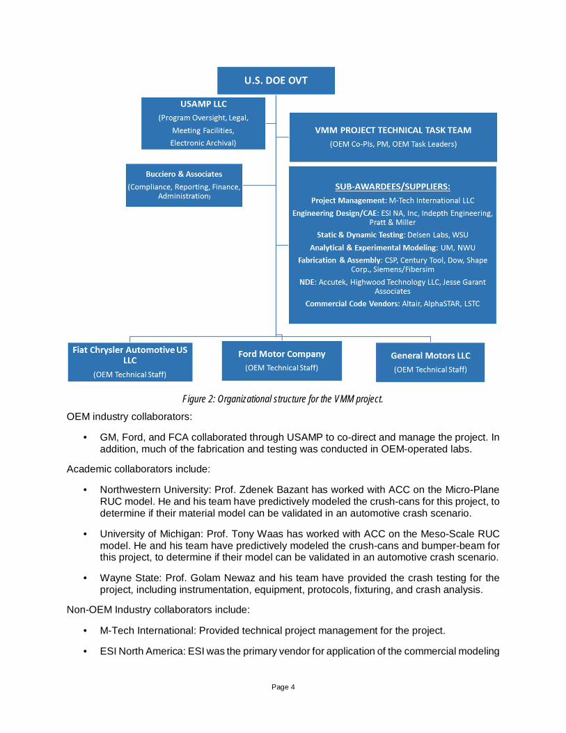
This project was funded by the DOE Office of Vehicle Technology (DOE OVT), which providedcontinued oversight to make sure the project was on track to meet its goals and timing. It broughttogether a large number of participating organizations and individuals. Participating organizationsand their primary roles are summarized below and in Figure 2.
Page 4
Figure 2: Organizational structure for the VMM project.
OEM industry collaborators:
· GM, Ford, and FCA collaborated through USAMP to co-direct and manage the project. Inaddition, much of the fabrication and testing was conducted in OEM-operated labs.
Academic collaborators include:
· Northwestern University: Prof. Zdenek Bazant has worked with ACC on the Micro-PlaneRUC model. He and his team have predictively modeled the crush-cans for this project, todetermine if their material model can be validated in an automotive crash scenario.
· University of Michigan: Prof. Tony Waas has worked with ACC on the Meso-Scale RUCmodel. He and his team have predictively modeled the crush-cans and bumper-beam forthis project, to determine if their model can be validated in an automotive crash scenario.
· Wayne State: Prof. Golam Newaz and his team have provided the crash testing for theproject, including instrumentation, equipment, protocols, fixturing, and crash analysis.
Non-OEM Industry collaborators include:
· M-Tech International: Provided technical project management for the project.
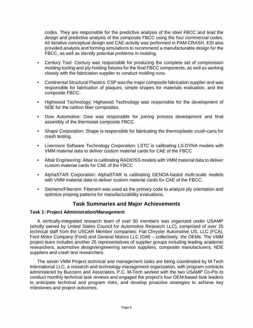
· ESI North America: ESI was the primary vendor for application of the commercial modeling
Page 5
codes. They are responsible for the predictive analysis of the steel FBCC and lead thedesign and predictive analysis of the composite FBCC using the four commercial codes.All iterative conceptual design and CAE activity was performed in PAM-CRASH. ESI alsoprovided analysis and forming simulations to recommend a manufacturable design for theFBCC, as well as identify potential problems in molding.
· Century Tool: Century was responsible for producing the complete set of compressionmolding tooling and ply-holding fixtures for the final FBCC components, as well as workingclosely with the fabrication supplier to conduct molding runs.
· Continental Structural Plastics: CSP was the major composite fabrication supplier and wasresponsible for fabrication of plaques, simple shapes for materials evaluation, and thecomposite FBCC.
· Highwood Technology: Highwood Technology was responsible for the development ofNDE for the carbon fiber composites.
· Dow Automotive: Dow was responsible for joining process development and finalassembly of the thermoset composite FBCC.
· Shape Corporation: Shape is responsible for fabricating the thermoplastic crush-cans forcrash testing.
· Livermore Software Technology Corporation: LSTC is calibrating LS-DYNA models withVMM material data to deliver custom material cards for CAE of the FBCC
· Altair Engineering: Altair is calibrating RADIOSS models with VMM material data to delivercustom material cards for CAE of the FBCC
· AlphaSTAR Corporation: AlphaSTAR is calibrating GENOA-based multi-scale modelswith VMM material data to deliver custom material cards for CAE of the FBCC.
· Siemens/Fibersim: Fibersim was used as the primary code to analyze ply orientation andoptimize prepreg patterns for manufacturability evaluations.
Task Summaries and Major AchievementsTask 1: Project Administration/Management
A vertically-integrated research team of over 50 members was organized under USAMP(wholly owned by United States Council for Automotive Research LLC), comprised of over 25technical staff from the USCAR Member companies: Fiat Chrysler Automotive US, LLC (FCA),Ford Motor Company (Ford) and General Motors LLC (GM) – collectively, the OEMs. The VMMproject team includes another 25 representatives of supplier groups including leading academicresearchers, automotive design/engineering service suppliers, composite manufacturers, NDEsuppliers and crash test researchers.
The seven VMM Project technical and management tasks are being coordinated by M-TechInternational LLC, a research and technology management organization, with program contractsadministered by Bucciero and Associates, P.C. M-Tech worked with the two USAMP Co-PIs toconduct monthly technical task reviews and engaged the project’s four OEM-based task leadersto anticipate technical and program risks, and develop proactive strategies to achieve keymilestones and project outcomes.

Page 6
Task 2: Experimental/Analytical Characterization of Crash Testing of a Steel FBCC
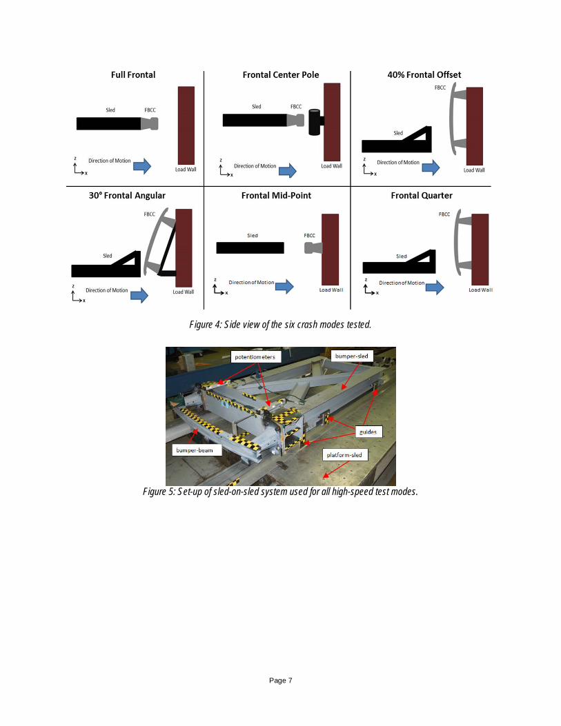
Testing of a steel FBCC system was used to develop test protocols and determineperformance benchmarks used to evaluate the carbon fiber system. See companion report“Validation of Material Models: Physical Crash Testing of Composite Bumper-Beams” for furtherdetails on the crash test methods and results.[1] Specifically, acceleration, force, deformation timehistories, as well as force-displacement curves were used to develop design requirements.Beams were tested in six crash modes: full frontal at 35 mph, 40% offset at 30 mph, 30° angularat 20 mph, and center pole impact at 20 mph. Low speed damageability tests were also conductedat 10 mph at center and quarter impact. See Figure 3 and Figure 4 for schematics of these modes.In addition, these tests were used as a baseline to determine the accuracy of the commercialcrash software models (PAM-CRASH, LS-DYNA, Abaqus and RADIOSS) for predicting eachcrash mode.
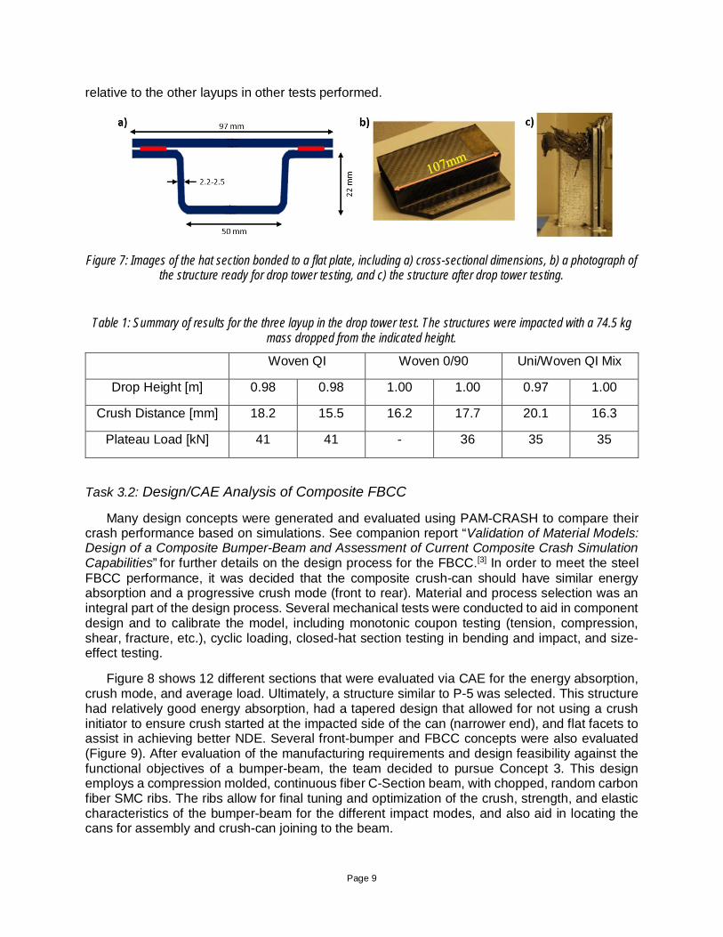
For all test modes, a sled-on-sled setup was employed (Figure 5). The followingmeasurements were recorded to use in comparing crash model predictions: accelerations usingaccelerometers, force using the accelerometers and load cells, overall system displacement usinghigh-speed video analysis and accelerometers, and crush-can deformation using potentiometersand high-speed video analysis. A sample testing result for full frontal impact is shown in Figure 6,showing good repeatability. Steel beams absorb energy through plastic deformation by foldingupon itself. For full frontal, average crush force was approximately 225 kN and crush distancewas 175 mm.
Figure 3: Top view of the six crash modes tested.
Page 7
Figure 4: Side view of the six crash modes tested.
Figure 5: Set-up of sled-on-sled system used for all high-speed test modes.

Page 8
Figure 6: Samples crash results for full frontal testing of the steel FBCC, including a) photographs of a beamfollowing a test, and b) force vs displacement for all the beams tested.
Task 3: Design of a Composite FBCC
Task 3.1: Material and Process Selection
While this is a research effort and not directly intended at production of a commercialautomotive subsystem, it is important to ensure that we are studying materials and processes thatcould be used in volume automotive production. In particular, a pathway towards rapid processingwas a key consideration. We selected compression molding of prepreg for the primary structuralelements because it enables production of a high performance composite in a relatively shortcycle time and with minimal investment in specialized equipment. See companion report“Validation of Material Models: Thermoset Composite Materials and Processing for a CompositeBumper-Beam System” for further details on the material selection and part manufacturingprocesses for thermoset systems.[2] The prepreg chosen was composed of standard moduluscarbon fiber and an epoxy resin. Both unidirectional and woven prepregs were considered. Sheetmolding compound (SMC) was co-molded with the prepreg to produce complex geometries,including the ribs of the bumper-beam and rear flanges of the crush-cans. The sheet moldingcompound used was composed of 1-inch randomly oriented carbon fibers and a vinyl ester resin.
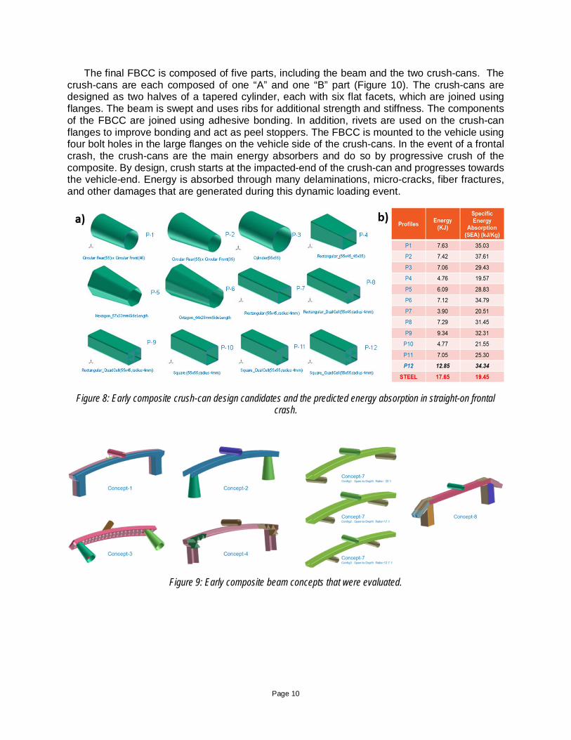
Layup of the prepreg was also an important factor to consider to obtain the maximum crashperformance. Several tests were used to compare some various layups. Standard coupon testswere used to compare the tensile, compression, shear, and flexural performance of various layupsof prepreg molded as flat plaques. Impact and flexure testing of a simple structure, a closed-hatsection, was used to assess the moldability of the layups and their performance under loads moresimilar to those experienced within the actual FBCC. Figure 7 shows images of a crush tube madeby bonding a portion of the hat section to a flat plate, before and after an impact test. Results forthree layups examined are given in Table 1. The three layups were: “Woven 0/90” with[0/90/0/90/0/901/2]s, “Woven QI” with [0/90/45/-45/0/901/2]s, and “Uni/Woven QI Mix”[0/0/0/90/45/901/2]s. In the Uni/Woven QI Mix layup, layers 1, 2, 5, 10, and 11 were unidirectionalfiber, while the rest were woven. Ultimately, a layup composed of only woven prepreg in a quasi-isotropic configuration was chosen for its superior performance in impact and good performance
Page 9
relative to the other layups in other tests performed.
Figure 7: Images of the hat section bonded to a flat plate, including a) cross-sectional dimensions, b) a photograph ofthe structure ready for drop tower testing, and c) the structure after drop tower testing.
Table 1: Summary of results for the three layup in the drop tower test. The structures were impacted with a 74.5 kgmass dropped from the indicated height.
Woven QI Woven 0/90 Uni/Woven QI Mix
Drop Height [m] 0.98 0.98 1.00 1.00 0.97 1.00
Crush Distance [mm] 18.2 15.5 16.2 17.7 20.1 16.3
Plateau Load [kN] 41 41 - 36 35 35
Task 3.2: Design/CAE Analysis of Composite FBCC
Many design concepts were generated and evaluated using PAM-CRASH to compare theircrash performance based on simulations. See companion report “Validation of Material Models:Design of a Composite Bumper-Beam and Assessment of Current Composite Crash SimulationCapabilities” for further details on the design process for the FBCC.[3] In order to meet the steelFBCC performance, it was decided that the composite crush-can should have similar energyabsorption and a progressive crush mode (front to rear). Material and process selection was anintegral part of the design process. Several mechanical tests were conducted to aid in componentdesign and to calibrate the model, including monotonic coupon testing (tension, compression,shear, fracture, etc.), cyclic loading, closed-hat section testing in bending and impact, and size-effect testing.
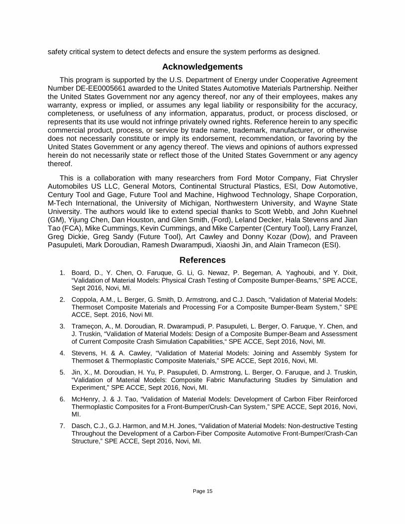
Figure 8 shows 12 different sections that were evaluated via CAE for the energy absorption,crush mode, and average load. Ultimately, a structure similar to P-5 was selected. This structurehad relatively good energy absorption, had a tapered design that allowed for not using a crushinitiator to ensure crush started at the impacted side of the can (narrower end), and flat facets toassist in achieving better NDE. Several front-bumper and FBCC concepts were also evaluated(Figure 9). After evaluation of the manufacturing requirements and design feasibility against thefunctional objectives of a bumper-beam, the team decided to pursue Concept 3. This designemploys a compression molded, continuous fiber C-Section beam, with chopped, random carbonfiber SMC ribs. The ribs allow for final tuning and optimization of the crush, strength, and elasticcharacteristics of the bumper-beam for the different impact modes, and also aid in locating thecans for assembly and crush-can joining to the beam.
Page 10
The final FBCC is composed of five parts, including the beam and the two crush-cans. Thecrush-cans are each composed of one “A” and one “B” part (Figure 10). The crush-cans aredesigned as two halves of a tapered cylinder, each with six flat facets, which are joined usingflanges. The beam is swept and uses ribs for additional strength and stiffness. The componentsof the FBCC are joined using adhesive bonding. In addition, rivets are used on the crush-canflanges to improve bonding and act as peel stoppers. The FBCC is mounted to the vehicle usingfour bolt holes in the large flanges on the vehicle side of the crush-cans. In the event of a frontalcrash, the crush-cans are the main energy absorbers and do so by progressive crush of thecomposite. By design, crush starts at the impacted-end of the crush-can and progresses towardsthe vehicle-end. Energy is absorbed through many delaminations, micro-cracks, fiber fractures,and other damages that are generated during this dynamic loading event.
Figure 8: Early composite crush-can design candidates and the predicted energy absorption in straight-on frontalcrash.
Figure 9: Early composite beam concepts that were evaluated.

Page 11
Figure 10: CAD model showing the structure of the FBCC.
Task 4: Manufacture/Assembly Composite FBCC
A total of 50 FBCCs were produced for testing, with three used for development of non-destructive evaluation (NDE) techniques and the rest for crash testing (Figure 11a). Seecompanion report “Validation of Material Models: Thermoset Composite Materials and Processingfor a Composite Bumper-Beam System” for further details on the material selection and partmanufacturing processes for thermoset systems.[4] FBCC components were produced bycompression molding using two-part tools. A total of three molds were required, including one ofthe bumper-beam, one for part “A” of the crush-can and one for part “B”. All components werecomposed of a combination of sheet molding compound (SMC) and continuous-fiber prepreg, co-molded and co-cured (Figure 11b). This approach allowed for the use of the high performanceprepreg in the main structural portions of the FBCC and the use of SMC to form complex structuralfeatures, including the beam ribs and crush-can flanges. The prepreg was precision cut using anautomated cutting table, while the SMC was cut to shape by hand and the quantity was verifiedby mass. Prior to molding, the prepreg was manually preformed into rough 3D then preformed toshape using dedicated forming tools and stored in a freezer on a buck until it was time to mold.See companion report “Validation of Material Models: Composite Fabric Manufacturing Studiesby Simulation and Experiment” for further details on the preform design process.[5] During molding,the parts were placed in the hot mold, cured, and removed. Following molding, the parts weretrimmed to final dimensions using CNC milling. Parts were then joined using adhesive bondingand rivets. See companion report “Validation of Material Models: Joining and Assembly Systemfor Thermoset & Thermoplastic Composite Materials” for further details on the FBCC joining andassembly. [6] Figure 12 shows the progression of the crush-can manufacture.
Several issues were identified during manufacturing of the FBCCs, including excessive resinrunoff during molding, wear and distortion of the aluminum tooling, and defects identified by NDE.Corrections were made for these issues as feasible. NDE of the components identified severaltypes of manufacturing defects, including fabric wrinkling, bunching, and stretching, whichcorrelated with the reduced material properties. This highlights the importance of consideringcomposite manufacturing when developing material models in order to capture locational variationin material properties that may occur near challenging geometries.
In addition to molding of thermoset-based parts, work was completed on manufacturing of

Page 12
thermoplastic crush-cans. See companion report “Validation of Material Models: Development ofCarbon Fiber Reinforced Thermoplastic Composites for a Front-Bumper Crush-Can System” forfurther details on the material selection and part manufacturing processes for thermoplasticsystems. Thermoplastics have the potential to absorb more energy than thermosets because oftheir generally higher fracture toughness. The crush-cans were composed of continuous carbonfiber/nylon prepreg for the main structural areas and chopped carbon fiber/nylon prepreg to takethe place of the SMC. Woven and non-crimped fabric (NCF) continuous prepreg were compared.Manufacturing of the thermoplastic crush-cans followed a similar procedure to that of thethermosets. However, for the molding step some changes were required. The prepreg waspreheated in a radiant oven to 260-315° C, then placed in the mold, which was maintained at 140°C. The mold was then closed and the prepreg took shape and hardened very rapidly and wasremoved. Crash testing of these components is pending and will be complete during the secondquarter of 2016.
Figure 11: a) Image of an assembled FBCC. b) Model of the FBCC showing the prepreg components in blue and theSMC components in orange.
Figure 12: Manufacture of a thermoset crush-can from preforming to joining.

Page 13
Task 5: Crash Test Composite FBCC
Crash testing of the composite FBCC will be completed for the same six modes that weretested for the steel beam. At the time of writing this report, test results were not available to bemade public because CAE predictions are still in progress. Results will be discussed in thepresentation and in future reports.
Task 6: Non-Destructive Evaluation of Composite Structure
The NDE team was tasked with the development of practical methods that can verify the buildof the carbon fiber composite materials and assemblies. See companion report “Validation ofMaterial Models: Non-destructive Testing Throughout the Development of a Carbon-FiberComposite Automotive Front-Bumper/Crash-Can Structure” for further details on the developmentof NDE methods for composite automotive systems.[7] NDE is critical to ensure the quality ofcarbon fiber composites in safety-critical parts, such as an FBCC assembly. Safety-critical,automotive components are typically 100% NDE inspected. There is also a major concern within-service monitoring due to the brittle nature of carbon fiber composites. Automotive componentstend to be highly 3-dimensional, fairly small, and produced at high rates when in mass-productioncompared to parts for aerospace or wind energy. NDE methods were selected to both addressthese features and remain consistent with methods already widely used in the automotiveenvironment. The four NDE methods selected were: 1) conventional x-ray radiography, 2)computed tomography (CT), 3) optical surface scanning and 4) ultrasonic pulse/echo using alinear phased array (UT-PA).
NDE methods were first evaluated on flat panels and the previously described hat-section.Two of the most important tasks in NDE development are to determine the type and size ofdiscrepancies that significantly reduce the material strength. The primary discrepancies observedfor the prepreg-based continuous fiber composites were delaminations and foreign mattercontamination. Compression-after-impact testing indicated a critical flaw size of 6 mm in diameterin twill-woven prepregs with a quasi-isotropic layup.
The crush-can and bumper-beam inspections presented significant NDE challenges. Acomparison of the methods on the crush-can is shown in Figure 13. The radiography and CTrequired relatively low x-ray energies (20-100 keV) to match the low attenuation of the 3- and 6-mm thick components. CT has the additional difficulty of having a trade-off between the resolutionand inspection volume. Usually these methods cannot find delaminations in thin sheets, althoughboth porosity and delaminations were detected in the ribs of the beam. Ultrasonic pulse/echo wasselected as the primary method to detect delaminations. Ultrasonic pulse/echo methods typicallyrequire careful alignment of the beam to be normal to the surface. To deal with this, the crush-cans were designed to have flat facets rather than a conical surface. This “design for inspection”was very beneficial and allowed careful inspection of the crush-can sides. On flat panels,ultrasonic pulse/echo was able to detect very small delaminations, image defects in 3-dimensions,and even determine ply orientation-angles. A linear ultrasonic phased array was used for both thecrush-can and bumper-beam. However, the front-bumper was too thick to fully inspect atfrequencies that would allow ply information.
To determine if the selected NDE methods had adequate sensitivity, thin 6-mm diameterinserts were molded into a crush-can and a bumper. Figure 13 shows the results for a crush-canwith both polyethylene (PE) and polytetrafluoroethylene (PTFE) inserts. Ultrasound readilydetected both insert types, at least up to 2-mm deep. Radiography detected all the PTFE inserts,but not the low-density PE inserts. The optical scans do no detect the inserts, as expected, butshow uniform thickness and <0.2 mm deviations from the CAD models.

Page 14
Figure 13: Detection sensitivity of a crush-can half using thin PE and PTFE inserts. a) Schematic of intended insertlocations, b) optical surface scan of thickness, c) low-energy radiograph showing PTFE inserts, and d) high-
frequency ultrasonic scan of PE and PTFE inserts.Task 7: Compare Experimental Results with Analytical Predictions
This task has not begun at the time of writing this report. The results of the physical testing ofthe carbon-fiber composite FBCC will be compared with the CAE predictions and design targetsto determine equivalency of performance. At least eight (8) different equivalency assessmentsare planned. The crash response predictions from the commercial codes and the ACC-developedacademic material models will be compared to the physical test results. This will establish thepredictive capabilities of these models. All analytical model predictions will be compared with eachother, to determine the relative utility of these models, identify key gaps in predictive values andrecommend best practices for application of each model.
Summary
The purpose of this project is to validate and assess material models used to predict crashperformance of automotive structures for energy absorption during crash events. The goal is toenable more widespread use of carbon fiber composite structures in automotive vehicles foradditional mass reduction to facilitate improved fuel economy and reduced greenhouse gasemissions. Crash tests on a production steel front-bumper/crush-can system were used toestablish performance standards for the design of the composite system. A new carbon fiberFBCC system was designed for this project. Materials and production processes were selectedto achieve excellent energy absorption with low mass and the potential for rapid production rates.Over 50 thermoset FBCCs were produced for testing, which is scheduled for completion duringthe second quarter of 2016. The FBCCs will be tested in six crash modes and compared topredictions from the commercial and academic models. NDE methods were evaluated and furtherdeveloped for analysis of the composite FBCC. NDE methods are particularly important for this
Page 15
safety critical system to detect defects and ensure the system performs as designed.
AcknowledgementsThis program is supported by the U.S. Department of Energy under Cooperative Agreement
Number DE-EE0005661 awarded to the United States Automotive Materials Partnership. Neitherthe United States Government nor any agency thereof, nor any of their employees, makes anywarranty, express or implied, or assumes any legal liability or responsibility for the accuracy,completeness, or usefulness of any information, apparatus, product, or process disclosed, orrepresents that its use would not infringe privately owned rights. Reference herein to any specificcommercial product, process, or service by trade name, trademark, manufacturer, or otherwisedoes not necessarily constitute or imply its endorsement, recommendation, or favoring by theUnited States Government or any agency thereof. The views and opinions of authors expressedherein do not necessarily state or reflect those of the United States Government or any agencythereof.
This is a collaboration with many researchers from Ford Motor Company, Fiat ChryslerAutomobiles US LLC, General Motors, Continental Structural Plastics, ESI, Dow Automotive,Century Tool and Gage, Future Tool and Machine, Highwood Technology, Shape Corporation,M-Tech International, the University of Michigan, Northwestern University, and Wayne StateUniversity. The authors would like to extend special thanks to Scott Webb, and John Kuehnel(GM), Yijung Chen, Dan Houston, and Glen Smith, (Ford), Leland Decker, Hala Stevens and JianTao (FCA), Mike Cummings, Kevin Cummings, and Mike Carpenter (Century Tool), Larry Franzel,Greg Dickie, Greg Sandy (Future Tool), Art Cawley and Donny Kozar (Dow), and PraveenPasupuleti, Mark Doroudian, Ramesh Dwarampudi, Xiaoshi Jin, and Alain Tramecon (ESI).
References1. Board, D., Y. Chen, O. Faruque, G. Li, G. Newaz, P. Begeman, A. Yaghoubi, and Y. Dixit,
“Validation of Material Models: Physical Crash Testing of Composite Bumper-Beams,” SPE ACCE,Sept 2016, Novi, MI.
2. Coppola, A.M., L. Berger, G. Smith, D. Armstrong, and C.J. Dasch, “Validation of Material Models:Thermoset Composite Materials and Processing For a Composite Bumper-Beam System,” SPEACCE, Sept. 2016, Novi MI.
3. Trameçon, A., M. Doroudian, R. Dwarampudi, P. Pasupuleti, L. Berger, O. Faruque, Y. Chen, andJ. Truskin, “Validation of Material Models: Design of a Composite Bumper-Beam and Assessmentof Current Composite Crash Simulation Capabilities,“ SPE ACCE, Sept 2016, Novi, MI.
4. Stevens, H. & A. Cawley, “Validation of Material Models: Joining and Assembly System forThermoset & Thermoplastic Composite Materials,” SPE ACCE, Sept 2016, Novi, MI.
5. Jin, X., M. Doroudian, H. Yu, P. Pasupuleti, D. Armstrong, L. Berger, O. Faruque, and J. Truskin,“Validation of Material Models: Composite Fabric Manufacturing Studies by Simulation andExperiment,” SPE ACCE, Sept 2016, Novi, MI.
6. McHenry, J. & J. Tao, “Validation of Material Models: Development of Carbon Fiber ReinforcedThermoplastic Composites for a Front-Bumper/Crush-Can System,” SPE ACCE, Sept 2016, Novi,MI.
7. Dasch, C.J., G.J. Harmon, and M.H. Jones, “Validation of Material Models: Non-destructive TestingThroughout the Development of a Carbon-Fiber Composite Automotive Front-Bumper/Crash-CanStructure,” SPE ACCE, Sept 2016, Novi, MI.