Embed Size (px)
Citation preview
V-DW2425A / V-DW2440 and V-DW11025A / V-DW11040A
The Sapling Company, Inc.1633 Republic RoadHuntingdon Valley, PA 19006
215.322.6063 P.215.322.8498 F.www.sapling-inc.com
Installation Manual V1.05

2
Valcom, Inc.5614 Hollins RoadRoanoke, VA 24019
540-563-2000 P.540-362-9800 F.www.valcom.com
Table of Contents
Valcom Wireless Digital Clock
Table of Contents—2
Metal Surface (Wall) Mount Installation —3
Connecting the Clocks to the Metal Double Mount Housing —4
Metal Double Mount Installation—5
Plastic Surface (Wall) Mount Installation—6
Plastic Surface (Wall) Mount Installation—7
Plastic Double Mount Installation—8
Plastic Double Mount Installation—9
Plastic Double Mount Installation—10
Wiring Information and Jumper Settings—11
Frequently Asked Questions—12
Troubleshooting—13
FCC Wants You to Know—14
*manuals may change without prior notice

3
Valcom, Inc.5614 Hollins RoadRoanoke, VA 24019
540-563-2000 P.540-362-9800 F.www.valcom.com
1. Mount the wall mount box into the double gang box using four machine screws (#6-32) including in the kit.
2. Connect the ground wire into the flush mount box using tooth lockwasher and the machine screw nut (included in the kit).
3. Disconnect the red filter from the display panel.
4. Connect the wiring as shown on the wiring diagram.
5. IMPORTANT: If using a low voltage system (24 volt) make sure that the transformer is an isolated transformer.
6. Mount the display panel into the flush mount box using four (4) black machine screws (#6, included in the kit). Make sure the switches are on the right side.
7. Snap the red filter into the display panel.
Metal Surface (Wall) Mount Installation
4
Valcom, Inc.5614 Hollins RoadRoanoke, VA 24019
540-563-2000 P.540-362-9800 F.www.valcom.com
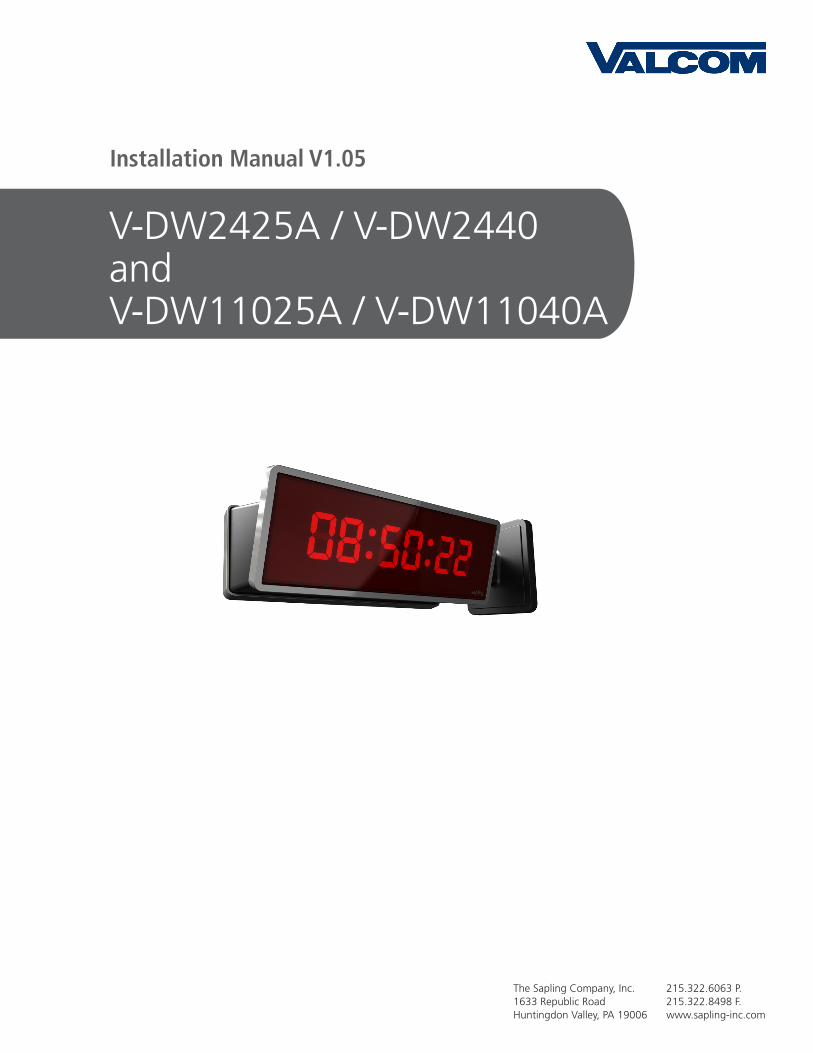
1. Connect CON 1 to P5 on Clock 1. Make sure the polarity is followed as shown in the diagram.
2. Connect CON2 to P2 on Clock 1.
3. Connect CON 3 to P2 on Clock 2.
If you have any questions, please contact Sapling Technical Support at (888) 809-6063.
Connecting the Clocks to the Metal Double Mount Housing

5
Valcom, Inc.5614 Hollins RoadRoanoke, VA 24019
540-563-2000 P.540-362-9800 F.www.valcom.com
1. Screw hanger/mounting rod (included in the kit) into the crossbar (also included in the kit).
2. Insert wires through hanger/mounting rod.
3. Install crossbar using two (2) #6-32 screws into double gang box.
4. Mount the double mount box into the clock base using two (2) #6 nuts and Tooth Lockwasher #6. (The double mount can be mounted either on the wall or on the ceiling).
5. Insert the two (2) locking hole plugs (0.187”) and the locking hole plug (0.562”) into the unused holes.
6. Insert double mount case onto the hanger/mounting rod.
7. Insert the support bracket onto the hanger/mounting rod.
8. Screw the two (2) nuts (included in the kit) onto hanger/mounting rod and secure the clock base to wall.
9. Connect the ground wire into the double mount box using the tooth lockwasher and machine screw nut (included in the kit).
10. Disconnect the red filter from the display panel.
11. Connect the wiring as shown on the wiring diagram.
12. IMPORTANT: If using a low voltage system (24 volt) make sure that the transformer is an isolated transformer.
13. Mount the display panel on one side of the double mount box using four (4) black machine screws (#6, included in the kit). Make sure the switches are on the right side.
14. Snap the red filter into the display panel.
15. Repeat steps 9-13 for the second clock.
Metal Double Mount Installation

6
Valcom, Inc.5614 Hollins RoadRoanoke, VA 24019
540-563-2000 P.540-362-9800 F.www.valcom.com
Plastic Surface (Wall) Mount Installation
ew
q
rt
y
7
Valcom, Inc.5614 Hollins RoadRoanoke, VA 24019
540-563-2000 P.540-362-9800 F.www.valcom.com
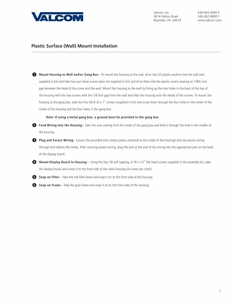
Plastic Surface (Wall) Mount Installation
qMount Housing to Wall and/or Gang Box - To mount the housing to the wall, drive two (2) plastic anchors into the wall (not
supplied in kit) and take two pan head screws (also not supplied in kit) and drive them into the plastic inserts leaving an 1/8th inch
gap between the head of the screw and the wall. Mount the housing to the wall by lining up the two holes in the back of the top of
the housing with the two screws with the 1/8 inch gap from the wall and slide the housing onto the heads of the screws. To mount the
housing to the gang box, take the four (4) 6-32 x 1” screws (supplied in kit) and screw them through the four holes in the center of the
inside of the housing and the four holes in the gang box.
Note: If using a metal gang box, a ground must be provided to the gang box.
wFeed Wiring Into the Housing - Take the wire coming from the inside of the gang box and feed it through the hole in the middle of
the housing.
ePlug and Secure Wiring - Loosen the provided wire clamp (comes attached to the inside of the housing) and slip excess wiring
through and tighten the clamp. After securing excess wiring, plug the jack at the end of the wiring into the appropriate jack on the back
of the display board.
rMount Display Board to Housing - Using the four (4) self tapping, 6-19 x 1/2” flat head screws supplied in the assembly kit, take
the display board and screw it to the front side of the clock housing (4 screws per clock).
tSnap on Filter - Take the red filter bezel and snap it on to the front side of the housing.
ySnap on Frame - Take the gray frame and snap it on to the front side of the housing.

8
Valcom, Inc.5614 Hollins RoadRoanoke, VA 24019
540-563-2000 P.540-362-9800 F.www.valcom.com
Plastic Double Mount Installation
qt
i
a
y
r
ww
e
u
o
9
Valcom, Inc.5614 Hollins RoadRoanoke, VA 24019
540-563-2000 P.540-362-9800 F.www.valcom.com
Plastic Double Mount Installation
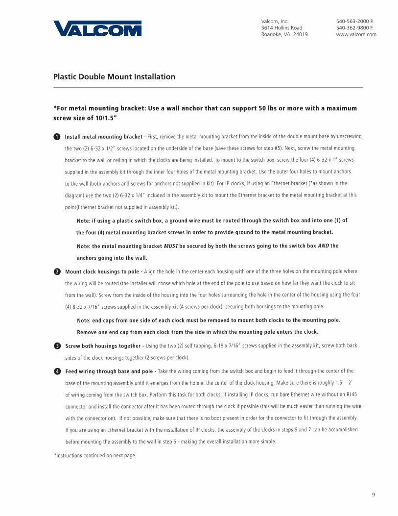
*For metal mounting bracket: Use a wall anchor that can support 50 lbs or more with a maximum
screw size of 10/1.5”
qInstall metal mounting bracket - First, remove the metal mounting bracket from the inside of the double mount base by unscrewing
the two (2) 6-32 x 1/2” screws located on the underside of the base (save these screws for step #5). Next, screw the metal mounting
bracket to the wall or ceiling in which the clocks are being installed. To mount to the switch box, screw the four (4) 6-32 x 1” screws
supplied in the assembly kit through the inner four holes of the metal mounting bracket. Use the outer four holes to mount anchors
to the wall (both anchors and screws for anchors not supplied in kit). For IP clocks, if using an Ethernet bracket (*as shown in the
diagram) use the two (2) 6-32 x 1/4” included in the assembly kit to mount the Ethernet bracket to the metal mounting bracket at this
point(Ethernet bracket not supplied in assembly kit).
Note: if using a plastic switch box, a ground wire must be routed through the switch box and into one (1) of
the four (4) metal mounting bracket screws in order to provide ground to the metal mounting bracket.
Note: the metal mounting bracket MUST be secured by both the screws going to the switch box AND the
anchors going into the wall.
wMount clock housings to pole - Align the hole in the center each housing with one of the three holes on the mounting pole where
the wiring will be routed (the installer will chose which hole at the end of the pole to use based on how far they want the clock to sit
from the wall). Screw from the inside of the housing into the four holes surrounding the hole in the center of the housing using the four
(4) 8-32 x 7/16” screws supplied in the assembly kit (4 screws per clock), securing both housings to the mounting pole.
Note: end caps from one side of each clock must be removed to mount both clocks to the mounting pole.
Remove one end cap from each clock from the side in which the mounting pole enters the clock.
e Screw both housings together - Using the two (2) self tapping, 6-19 x 7/16” screws supplied in the assembly kit, screw both back
sides of the clock housings together (2 screws per clock).
r Feed wiring through base and pole - Take the wiring coming from the switch box and begin to feed it through the center of the
base of the mounting assembly until it emerges from the hole in the center of the clock housing. Make sure there is roughly 1.5’ - 2’
of wiring coming from the switch box. Perform this task for both clocks. If installing IP clocks, run bare Ethernet wire without an RJ45
connector and install the connector after it has been routed through the clock if possible (this will be much easier than running the wire
with the connector on). If not possible, make sure that there is no boot present in order for the connector to fit through the assembly.
If you are using an Ethernet bracket with the installation of IP clocks, the assembly of the clocks in steps 6 and 7 can be accomplished
before mounting the assembly to the wall in step 5 - making the overall installation more simple.
*instructions continued on next page
10
Valcom, Inc.5614 Hollins RoadRoanoke, VA 24019
540-563-2000 P.540-362-9800 F.www.valcom.com
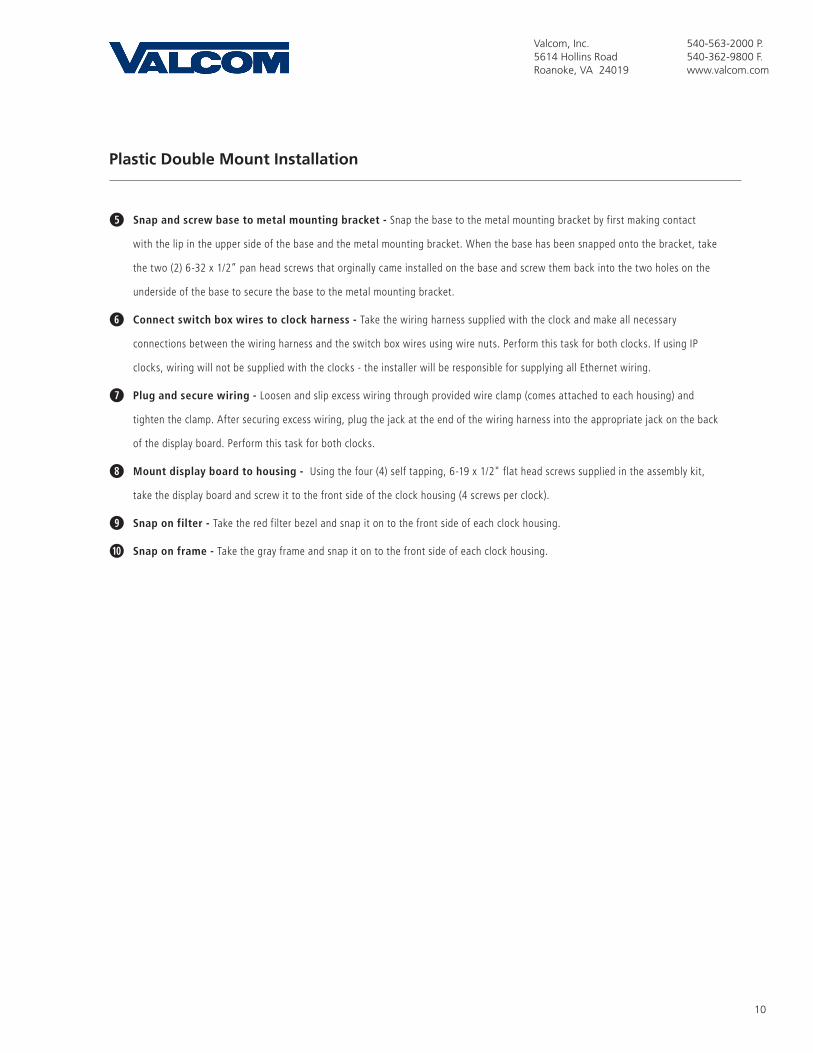
Plastic Double Mount Installation
t Snap and screw base to metal mounting bracket - Snap the base to the metal mounting bracket by first making contact
with the lip in the upper side of the base and the metal mounting bracket. When the base has been snapped onto the bracket, take
the two (2) 6-32 x 1/2” pan head screws that orginally came installed on the base and screw them back into the two holes on the
underside of the base to secure the base to the metal mounting bracket.
yConnect switch box wires to clock harness - Take the wiring harness supplied with the clock and make all necessary
connections between the wiring harness and the switch box wires using wire nuts. Perform this task for both clocks. If using IP
clocks, wiring will not be supplied with the clocks - the installer will be responsible for supplying all Ethernet wiring.
uPlug and secure wiring - Loosen and slip excess wiring through provided wire clamp (comes attached to each housing) and
tighten the clamp. After securing excess wiring, plug the jack at the end of the wiring harness into the appropriate jack on the back
of the display board. Perform this task for both clocks.
iMount display board to housing - Using the four (4) self tapping, 6-19 x 1/2" flat head screws supplied in the assembly kit,
take the display board and screw it to the front side of the clock housing (4 screws per clock).
oSnap on filter - Take the red filter bezel and snap it on to the front side of each clock housing.
aSnap on frame - Take the gray frame and snap it on to the front side of each clock housing.
11
Valcom, Inc.5614 Hollins RoadRoanoke, VA 24019
540-563-2000 P.540-362-9800 F.www.valcom.com
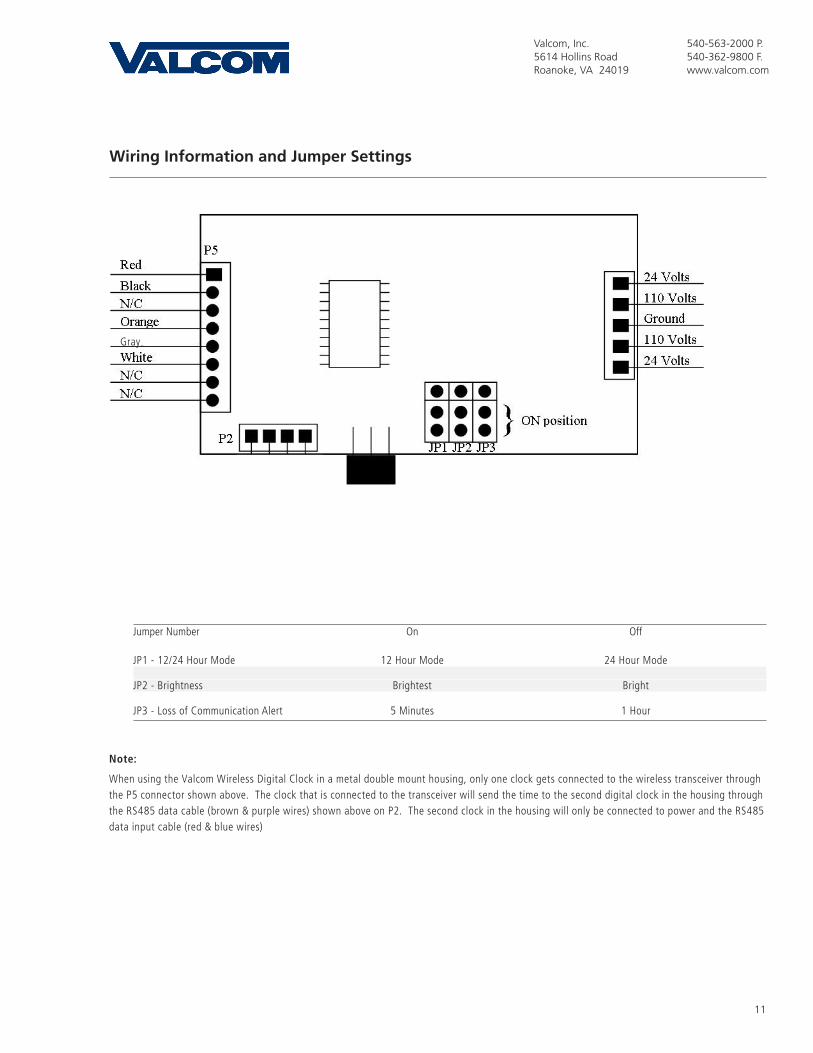
Jumper Number On Off
JP1 - 12/24 Hour Mode 12 Hour Mode 24 Hour Mode
JP2 - Brightness Brightest Bright
JP3 - Loss of Communication Alert 5 Minutes 1 Hour
Note:
When using the Valcom Wireless Digital Clock in a metal double mount housing, only one clock gets connected to the wireless transceiver through the P5 connector shown above. The clock that is connected to the transceiver will send the time to the second digital clock in the housing through the RS485 data cable (brown & purple wires) shown above on P2. The second clock in the housing will only be connected to power and the RS485 data input cable (red & blue wires)
Wiring Information and Jumper Settings
Gray
12
Valcom, Inc.5614 Hollins RoadRoanoke, VA 24019
540-563-2000 P.540-362-9800 F.www.valcom.com
Frequently Asked Questions
Will the clock cause interference with any of my other wireless devices?No, the Valcom Wireless Digital Clock works on 915 - 928 MHz frequency-hopping technology. The clock switches frequencies automatically when the receiver and transmitter are open, thus interference is avoided..
How long does it take for the clock to receive a signal?Upon power up, the clock will look for the signal for 30 minutes. The Valcom Wireless Digital Clock will look for the signal every minute thereafter.
I have double mount clocks and only one clock got the signal.If only one clock gets the signal check the connection from the two clocks. Only one clock should be connected to the wireless transceiver; the other clock gets the time via the RS485 data cable. Make sure the clock that is connected to the wireless board has the RS485 cable with the purple and brown wires connected to P2, if not flip around the cable.
Do the Valcom Wireless Digital Clocks work together with Valcom’s wireless analog clocks?Yes, the Valcom Wireless Digital Clocks work integrally with Valcom’s wireless analog clocks.
How many ways can I mount the Valcom Wireless Digital Clock?The clock can be mounted in either surface or double mount. Please see pages 3 through 10 for more information on mounting instructions.
Can the Valcom Wireless Digital Clock be used as an independent clock?No, the Valcom Wireless Digital Clock requires a communication input and must be used with either a Valcom Transceiver or Repeater.
What will happen if the clock is not receiving a signal?The colon on the display will flash every second.
How can the clock be powered?The clock is available in 110 volt AC models or in 24 volt AC/DC models.

13
Valcom, Inc.5614 Hollins RoadRoanoke, VA 24019
540-563-2000 P.540-362-9800 F.www.valcom.com
Troubleshooting
What happens if the clock doesn’t power up?Make sure the wiring is correct. If the clock is 24 volt, the power should be on the orange and yellow wires of the harness. If the clock is 110 volt, the power should be on the black and white wires. The middle (green) wire is ground. If the wiring is correct, take a volt meter and measure the voltage. For 24 volt models, the voltage should be between 14 - 28 volts. For 110 volt models, the voltage should read 85 - 135 volts.
What happens if the clock does not receive the signal?Take the clock within close proximity to the transmitter and power the clock. If the clock does not correct, call Valcom technical support.
I have a location with a marginal signal. What should I do?Try to install a repeater in a nearby area to the location or install a 110 volt clock.

14
Valcom, Inc.5614 Hollins RoadRoanoke, VA 24019
540-563-2000 P.540-362-9800 F.www.valcom.com
This equipment has been tested and found to comply with the limits for a Class B digital device, pursuant to Part 15 of the FCC rules. These limits are designed to provide reasonable protection against harmful interference in a commercial installation. This equipment generates, uses and can radiate radio frequency energy and, if not installed and used in accordance with the instructions, may cause harmful interference to radio communications. However, there is no guarantee that interference will not occur in a particular installation. If this equipment does cause harmful interference to radio or television reception, which can be determined by turning the equipment off and on, the user is encouraged to try to correct the interference by one or more of the following measures:
a) Reorient or relocate the receiving antenna.
b) Increase the separation between the equipment and receiver.
c) Connect the equipment to an outlet on a circuit different from which the receiver is connected.
d) Consult the dealer or an experienced radio/TV technician.
FCC WARNING
Modifications not expressly approved by the manufacturer could void the user authority to operate the equipment under FCC Rules.
Note: For precautionary measures, FCC recommends a distance of 10cm from the clock to constant human physical exposure.
FCC Wants You to Know