Embed Size (px)
Citation preview

Vacuum, Surfaces & Coatings Group Technology Department
Vacuum System Reliability Illustrated with LHC
V. Baglin CERN TE-VSC, Geneva
2 ARW 2015, Knoxville, Tennessee, USA, April 29-May 1, 2015
Vacuum, Surfaces & Coatings Group Technology Department ARW 2015, Knoxville, Tennessee, USA, April 29-May
1, 2015 3
Reliability engineering, The ability of a system or component to perform its required functions under stated conditions for a specified period of time [1].
[1] Institute of Electrical and Electronics Engineers (1990) IEEE Standard Computer Dictionary: A Compilation of IEEE Standard Computer Glossaries. New York, NY ISBN 1-55937-079-3
A system must be think / produced to be reliable before being operated
I will introduce the main action taken in order a vacuum system is reliable during operation

Vacuum, Surfaces & Coatings Group Technology Department
4 ARW 2015, Knoxville, Tennessee, USA, April 29-May 1, 2015
OUTLINE
1. Study, Design, Procurement & Installation
2. Operation
3. Repair, Consolidation & Upgrade
4. Summary
Vacuum, Surfaces & Coatings Group Technology Department
5 ARW 2015, Knoxville, Tennessee, USA, April 29-May 1, 2015
1. Study, Design, Procurement & Installation

Vacuum, Surfaces & Coatings Group Technology Department
6 ARW 2015, Knoxville, Tennessee, USA, April 29-May 1, 2015
LHC from Study to Project • Communication & release of Official documents and books is mandatory to share pertinent information across the project
1991 1995 2004
Design study Conceptual design Design project

Vacuum, Surfaces & Coatings Group Technology Department
7 ARW 2015, Knoxville, Tennessee, USA, April 29-May 1, 2015
LHC Project
Design
Nominal Ultimate
Energy [TeV] 7
Luminosity [x1034 cm-2.s-1] 1.0 2.3
Current [mA] 584 860
Proton per bunch [x1011] 1.15 1.7
Number of bunches 2808
Bunch spacing [ns] 25
Normalised emittance [μm.rad] 3.75
β * [m] 0.55
Total crossing angle [μrad] 285
Critical energy [eV] 44.1
Photon flux [ph/m/s] 1 1017 1.5 1017
SR power [W/m] 0.22 0.33
Photon dose [ph/m/year] 1 1024 1.5 1024
• Defining and understanding the machine parameters impacting the vacuum system was a crucial part of the project
Vacuum, Surfaces & Coatings Group Technology Department
8 ARW 2015, Knoxville, Tennessee, USA, April 29-May 1, 2015
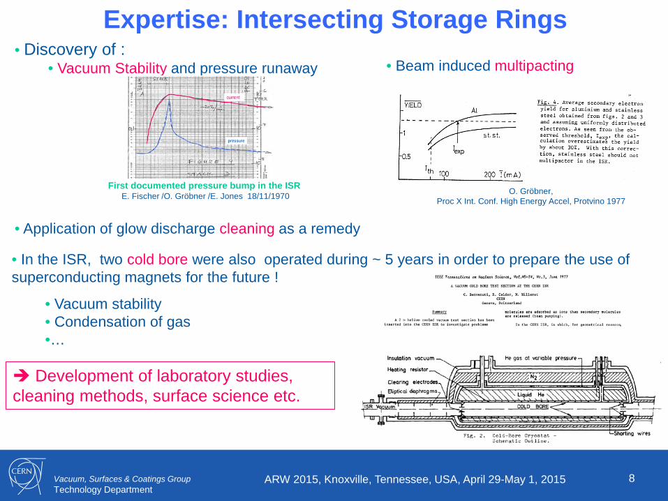
Expertise: Intersecting Storage Rings • Discovery of :
• Vacuum Stability and pressure runaway
• Application of glow discharge cleaning as a remedy
• In the ISR, two cold bore were also operated during ~ 5 years in order to prepare the use of superconducting magnets for the future !
• Vacuum stability • Condensation of gas •…
First documented pressure bump in the ISR E. Fischer /O. Gröbner /E. Jones 18/11/1970
• Beam induced multipacting
O. Gröbner, Proc X Int. Conf. High Energy Accel, Protvino 1977
Development of laboratory studies, cleaning methods, surface science etc.
Vacuum, Surfaces & Coatings Group Technology Department
9 ARW 2015, Knoxville, Tennessee, USA, April 29-May 1, 2015
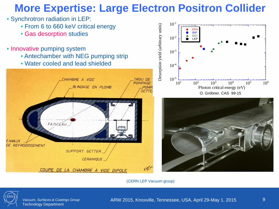
More Expertise: Large Electron Positron Collider • Synchrotron radiation in LEP:
• From 6 to 660 keV critical energy • Gas desorption studies
• Innovative pumping system
• Antechamber with NEG pumping strip • Water cooled and lead shielded
(CERN LEP Vacuum group)
10-5
10-4
10-3
10-2
10-1
101 102 103 104 105 106
EPAINPDCILEP
Des
orpt
ion
yiel
d (a
rbitr
ary
units
)
Photon critical energy (eV)O. Gröbner. CAS 99-15
Vacuum, Surfaces & Coatings Group Technology Department
10 ARW 2015, Knoxville, Tennessee, USA, April 29-May 1, 2015
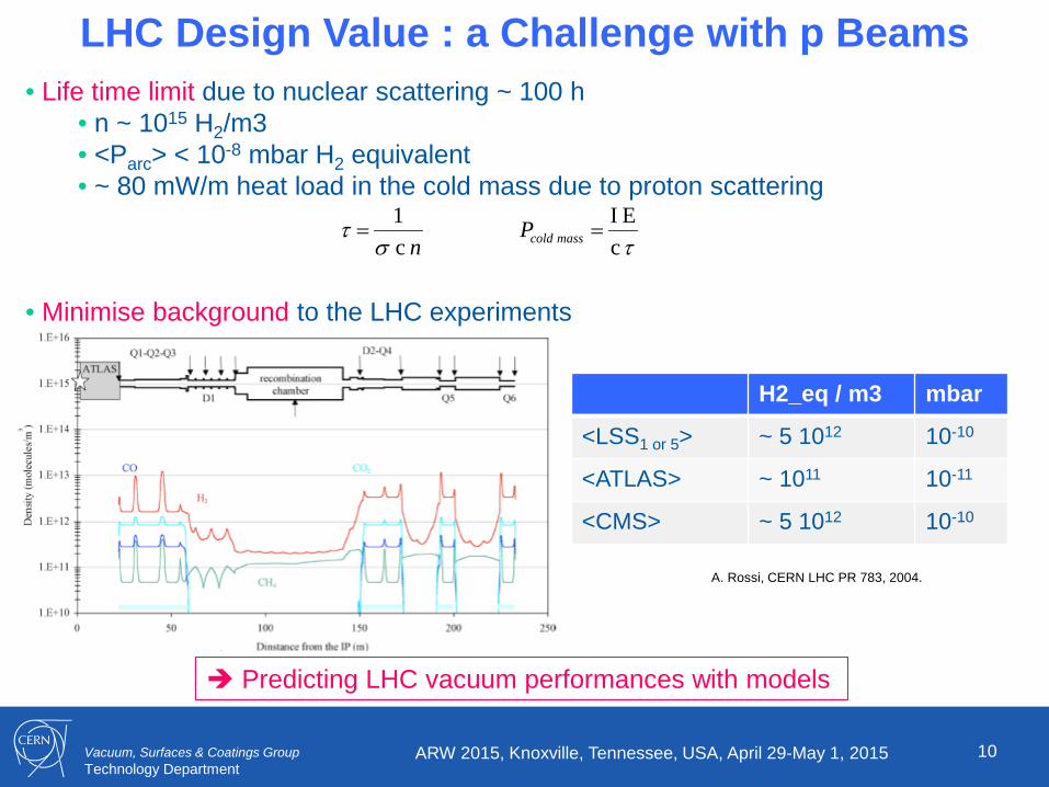
LHC Design Value : a Challenge with p Beams • Life time limit due to nuclear scattering ~ 100 h
• n ~ 1015 H2/m3 • <Parc> < 10-8 mbar H2 equivalent • ~ 80 mW/m heat load in the cold mass due to proton scattering
• Minimise background to the LHC experiments
n c 1
στ =
τ cE I =masscoldP
H2_eq / m3 mbar
<LSS1 or 5> ~ 5 1012 10-10
<ATLAS> ~ 1011 10-11
<CMS> ~ 5 1012 10-10
A. Rossi, CERN LHC PR 783, 2004.
Predicting LHC vacuum performances with models
Vacuum, Surfaces & Coatings Group Technology Department 11
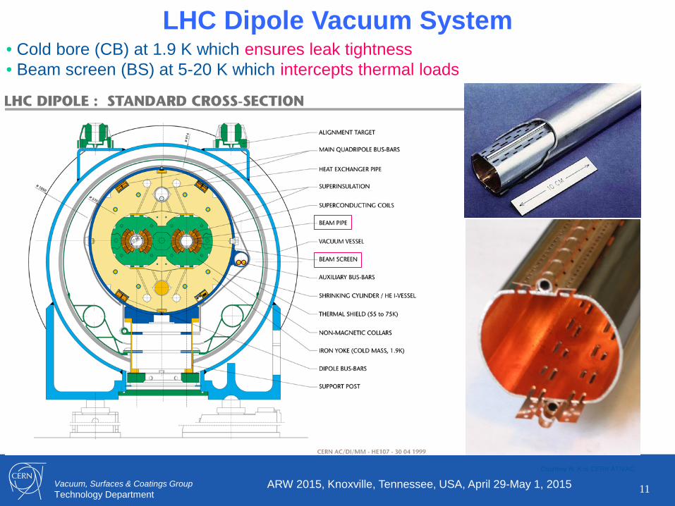
LHC Dipole Vacuum System • Cold bore (CB) at 1.9 K which ensures leak tightness • Beam screen (BS) at 5-20 K which intercepts thermal loads
Courtesy N. Kos CERN AT/VAC
ARW 2015, Knoxville, Tennessee, USA, April 29-May 1, 2015

Vacuum, Surfaces & Coatings Group Technology Department 12
New System: LHC Beam Screens
• Intercept the heat load induced by the circulating beam • Operate between 5 and 20 K • Pumping holes to control the gas density
Courtesy N. Kos CERN TE/VSC
ARW 2015, Knoxville, Tennessee, USA, April 29-May 1, 2015
• An innovative and complex system, produced at several 10 km scale !
Functional design map of beam screen
P. Lebrun et al., ICEC 2012
Vacuum, Surfaces & Coatings Group Technology Department 13
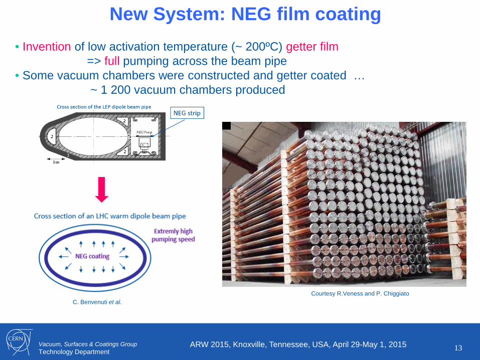
New System: NEG film coating
• Invention of low activation temperature (~ 200ºC) getter film => full pumping across the beam pipe
• Some vacuum chambers were constructed and getter coated … ~ 1 200 vacuum chambers produced
Courtesy R.Veness and P. Chiggiato
ARW 2015, Knoxville, Tennessee, USA, April 29-May 1, 2015
C. Benvenuti et al.

Vacuum, Surfaces & Coatings Group Technology Department 14
NEG Coating System: Industrialised Process
• Ti-Zr-V is coated by magnetron sputtering with Kr gas • ~ 1 μm thick • All room temperature vacuum chamber including the experimental beam pipe are coated with Ti-Zr-V • Performances are valided by XPS on witness sample
3mm wires of Ti, Zr
and V
manifold
Extensions + chambers Solenoid
L=8m φ=60cm
P. Costa Pinto, P. Chiggiato / Thin Solid Films 515 (2006) 382-388
ARW 2015, Knoxville, Tennessee, USA, April 29-May 1, 2015

Vacuum, Surfaces & Coatings Group Technology Department
15 ARW 2015, Knoxville, Tennessee, USA, April 29-May 1, 2015
Base Line Validation • Many studies conducted over ~ a decade with experts all around the world, some examples:
C. Scheuerlein et al. Appl.Surf.Sci 172(2001)
R. Cimino , I.R. Collins, App. Surf. Sci. 235, 231-235, (2004)
Material performance qualification System performance qualification
V. Anashin et al., J. Vac. Sci. Technol. A 14(4) (1996) 2618
A. Rossi, Proc. Ecloud’04

Vacuum, Surfaces & Coatings Group Technology Department
16 ARW 2015, Knoxville, Tennessee, USA, April 29-May 1, 2015
Design of components / assemblies • Design review (conceptual, detailed, production readiness …) • During LHC procurement, the LHC-VAC group internally reviewed all technical specifications and drawings :
• ensure compatibility across the vacuum system • allows optimisation across components and performance (standardisation) • use quality class (class A, approval circuit after control 1&2)
• Rule: rejects components, including in-kind, which do not meet VACUUM DESIGN APPROVAL
Technical specification & drawing validation State of the art material, cleaning methods, procedures
• Do’s and don’ts (just a few important ones from LHC design and experience) • No halogenated fluxes • No cold demountable joints • Helium envelopes are all-metal • Joining techniques need to be validated (materials, welding, DT) • No dye penetrant testing • Minimise thin wall components. • Combine RT leak and pressure test of components • Decide a policy for cold testing of critical components • Keep non-vacuum group manufacturing under control – assign a vac link person • Don’t allow deliveries until tightness certification is approved • Minimise number of welds to be tested in the tunnel • Many, many more • …
Vacuum, Surfaces & Coatings Group Technology Department
17 ARW 2015, Knoxville, Tennessee, USA, April 29-May 1, 2015
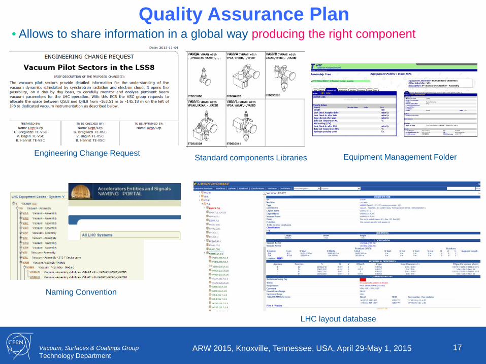
Quality Assurance Plan • Allows to share information in a global way producing the right component
Engineering Change Request Standard components Libraries Equipment Management Folder
Naming Convention
LHC layout database

Vacuum, Surfaces & Coatings Group Technology Department
18 ARW 2015, Knoxville, Tennessee, USA, April 29-May 1, 2015
Vacuum Layout • Define components, produce data based drawings and SCADA systems, ease installation and optimise future intervention (e.g. in radioactive areas)
Vacuum layout database Integration studies Installation drawings
SCADA
New components Production & follow up

Vacuum, Surfaces & Coatings Group Technology Department
Electrical
19 ARW 2015, Knoxville, Tennessee, USA, April 29-May 1, 2015
Infrastructure and Material • Adapted stores, components, tools and storage management are mandatory
Gaskets – Flanges - Pinch-off
Vacuum modules
Vacuum adapters
LHC’s spare Bake-out
Store
Remote tooling
Mobile Pumping group
Pinch-off
ARC
Mechanical NEG Activation

Vacuum, Surfaces & Coatings Group Technology Department
LSS Vacuum Sectors Vacuum Acceptance Tests • Prior installation all (several thousands) equipment have been baked and validated at the surface before installation in the tunnel:
• functional test • leak detection • residual gas composition • total outgassing rate
20 ARW 2015, Knoxville, Tennessee, USA, April 29-May 1, 2015
G. Cattenoz et al., IPAC 2014
Logistics, scheduling, coordinating & official reporting
Vacuum, Surfaces & Coatings Group Technology Department
LSS Vacuum Sectors
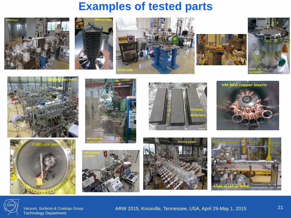
21 ARW 2015, Knoxville, Tennessee, USA, April 29-May 1, 2015
Examples of tested parts
Collimator jaws
Vacuum, Surfaces & Coatings Group Technology Department
22 ARW 2015, Knoxville, Tennessee, USA, April 29-May 1, 2015
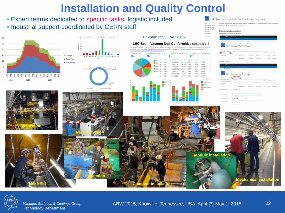
Installation and Quality Control • Expert teams dedicated to specific tasks, logistic included • Industrial support coordinated by CERN staff
Bake out
NEG activation
Chamber installation
Module installation
Mechanical installation
Inspection
Inspection
J. Sestak et al., IPAC 2015
Vacuum, Surfaces & Coatings Group Technology Department 23
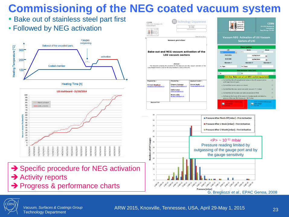
Commissioning of the NEG coated vacuum system • Bake out of stainless steel part first • Followed by NEG activation
ARW 2015, Knoxville, Tennessee, USA, April 29-May 1, 2015
Specific procedure for NEG activation Activity reports Progress & performance charts
G. Bregliozzi et al., EPAC Genoa, 2008
<P> ~ 10-11 mbar Pressure reading limited by
outgassing of the gauge port and by the gauge sensitivity

Vacuum, Surfaces & Coatings Group Technology Department
24 ARW 2015, Knoxville, Tennessee, USA, April 29-May 1, 2015
2. Operation

Vacuum, Surfaces & Coatings Group Technology Department
ARW 2015, Knoxville, Tennessee, USA, April 29-May 1, 2015 25
Vacuum Monitoring – Stand-By • General monitoring : check status of components, record of machine status • Stand-by with specific duties: answer to control room request, act on simple intervention, assist expert teams during complicate / delicate interventions • Stand-by must be trained !
Daily and weekly Reports Procedures

Vacuum, Surfaces & Coatings Group Technology Department
ARW 2015, Knoxville, Tennessee, USA, April 29-May 1, 2015 26
Pressure Follow-Up • Expert monitoring: check general trends and track / resolve specific issues, follow daily and detailed machine operation
Fill by fill monitoring
General trends
Tracking interlocks
Vacuum, Surfaces & Coatings Group Technology Department
27 ARW 2015, Knoxville, Tennessee, USA, April 29-May 1, 2015
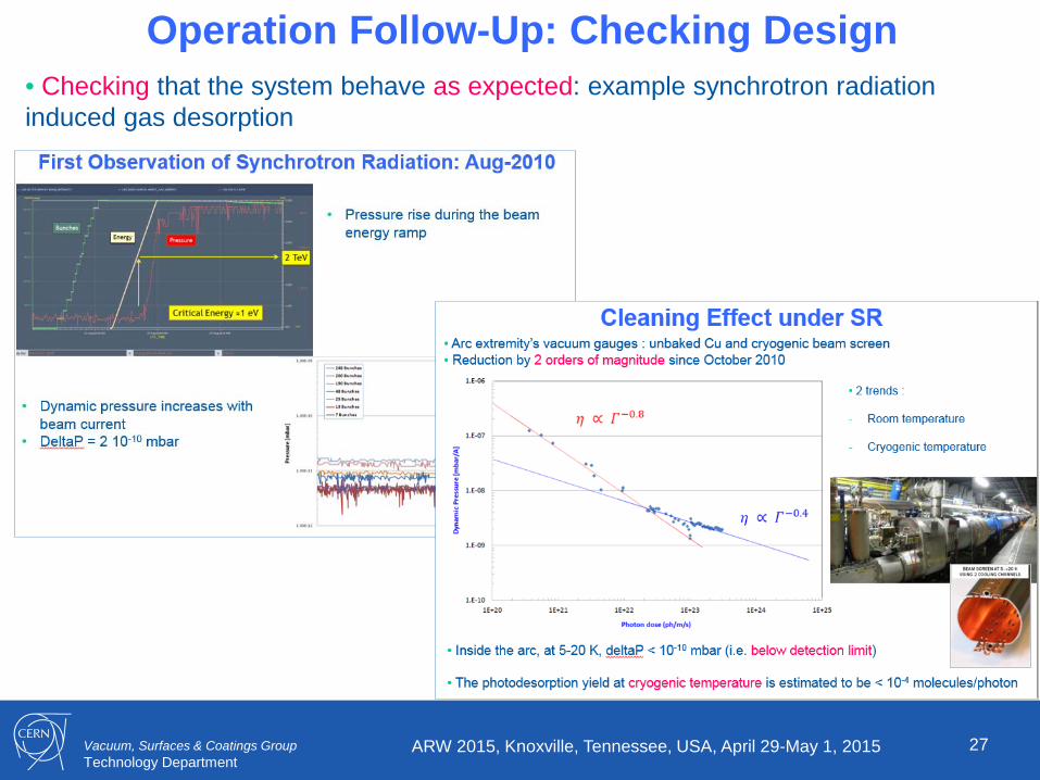
Operation Follow-Up: Checking Design • Checking that the system behave as expected: example synchrotron radiation induced gas desorption

Vacuum, Surfaces & Coatings Group Technology Department
28 ARW 2015, Knoxville, Tennessee, USA, April 29-May 1, 2015
Operation Follow-Up: Expertise • Assisting the control room during important phase of the commissioning: scrubbing run periods
Vacuum, Surfaces & Coatings Group Technology Department
29 ARW 2015, Knoxville, Tennessee, USA, April 29-May 1, 2015
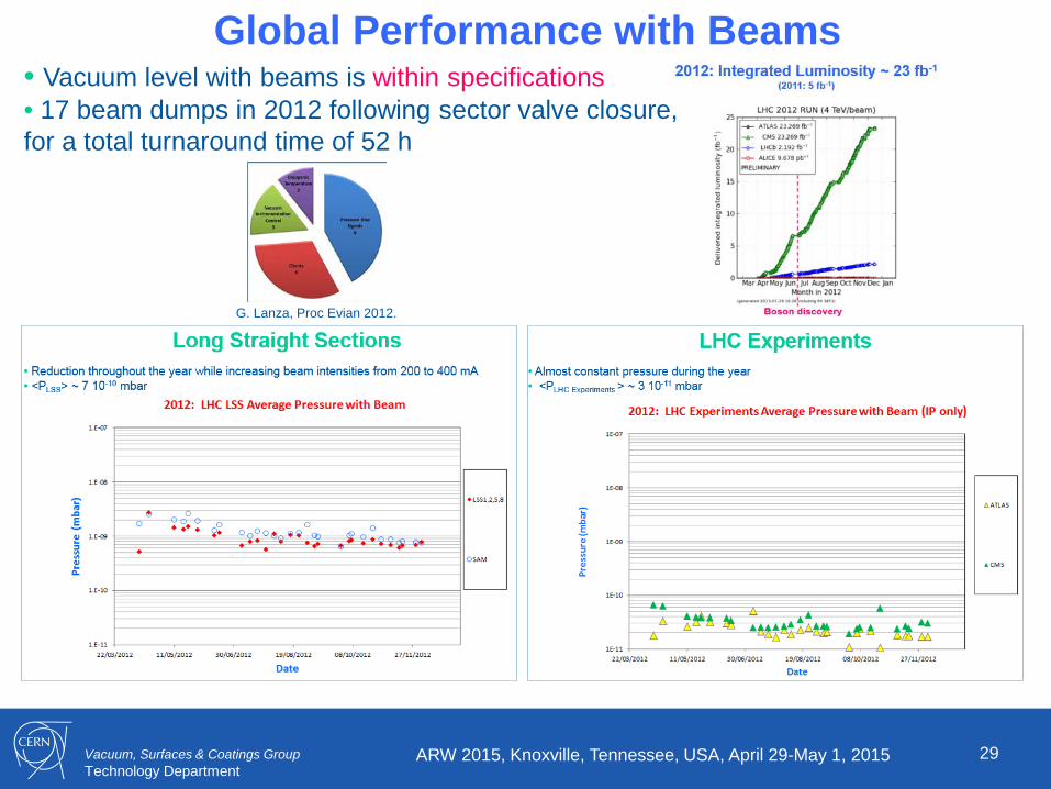
Global Performance with Beams • Vacuum level with beams is within specifications • 17 beam dumps in 2012 following sector valve closure, for a total turnaround time of 52 h
G. Lanza, Proc Evian 2012.
Vacuum, Surfaces & Coatings Group Technology Department
30 ARW 2015, Knoxville, Tennessee, USA, April 29-May 1, 2015
3. Repairs, Consolidation & Upgrade

Vacuum, Surfaces & Coatings Group Technology Department
Pressure Distribution after NEG Activation Fast Intervention: Ne venting • Allow to reduce the recovery time minimising the impact of vacuum performance:
31 ARW 2015, Knoxville, Tennessee, USA, April 29-May 1, 2015
Fast recovery following RF bridge repair: operation resumed in 3 days

Vacuum, Surfaces & Coatings Group Technology Department 32
Repair of Non-Conformities (2013-14) • As a consequence of the previous repair, a systematic X-ray analysis of all the vacuum modules was done: 1800 X-rays were taken during 2 years.
• The repair of 96 non-conform vacuum modules (~ 5% of the total) was needed to restore machine impedance and to avoid pressure spikes/excursion (i.e. avoid beam dumps).
• 52 RT vacuum sectors impacted out of which 29 are opened during LS1 on purpose ( ~ 200 kCHf manpower)
Conform
Courtesy A. Vidal, J-M. Dalin EN-MME
ARW 2015, Knoxville, Tennessee, USA, April 29-May 1, 2015
Non-conform: reduction of aperture
with increase of contact resistance
Identify and classify the non-conformities Repair them !
Vacuum, Surfaces & Coatings Group Technology Department 33
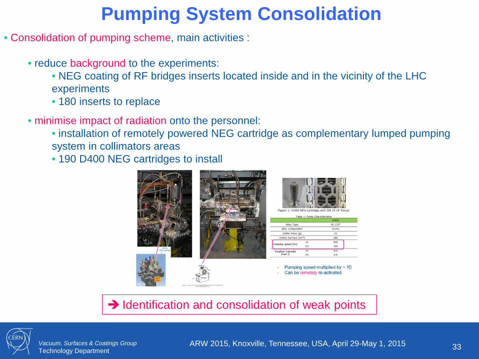
Pumping System Consolidation • Consolidation of pumping scheme, main activities :
• reduce background to the experiments: • NEG coating of RF bridges inserts located inside and in the vicinity of the LHC experiments • 180 inserts to replace
• minimise impact of radiation onto the personnel: • installation of remotely powered NEG cartridge as complementary lumped pumping system in collimators areas • 190 D400 NEG cartridges to install
ARW 2015, Knoxville, Tennessee, USA, April 29-May 1, 2015
Identification and consolidation of weak points

Vacuum, Surfaces & Coatings Group Technology Department 34
Specific Instrumentation
ARW 2015, Knoxville, Tennessee, USA, April 29-May 1, 2015
Pressure ratio yields the NEG sticking factor
NEG Pilot Sectors Vacuum Pilot Sectors
Improve the understanding of the LHC vacuum system with dedicated diagnostic
B. Henrist et al., IPAC 2015
Vacuum, Surfaces & Coatings Group Technology Department 35
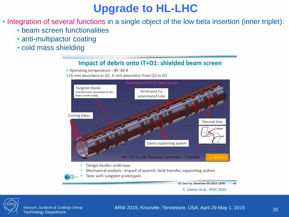
Upgrade to HL-LHC • Integration of several functions in a single object of the low beta insertion (inner triplet):
• beam screen functionalities • anti-multipactor coating • cold mass shielding
ARW 2015, Knoxville, Tennessee, USA, April 29-May 1, 2015
C. Garion et al., IPAC 2015
Vacuum, Surfaces & Coatings Group Technology Department
36 ARW 2015, Knoxville, Tennessee, USA, April 29-May 1, 2015
4. Summary
Vacuum, Surfaces & Coatings Group Technology Department 37
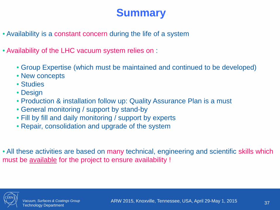
Summary
• Availability is a constant concern during the life of a system
• Availability of the LHC vacuum system relies on :
• Group Expertise (which must be maintained and continued to be developed) • New concepts • Studies • Design • Production & installation follow up: Quality Assurance Plan is a must • General monitoring / support by stand-by • Fill by fill and daily monitoring / support by experts • Repair, consolidation and upgrade of the system
• All these activities are based on many technical, engineering and scientific skills which must be available for the project to ensure availability !
ARW 2015, Knoxville, Tennessee, USA, April 29-May 1, 2015

Vacuum, Surfaces & Coatings Group Technology Department
38 ARW 2015, Knoxville, Tennessee, USA, April 29-May 1, 2015
Credits & Acknowledgments
• The slides presented here are the fruit of the work of many CERN and external collaborators who participated to the design and installation of the LHC vacuum system under the successive directions of A.G. Mathewson, O. Gröbner and P. Strubin
• Credits and warm thanks should be address also to J M. Jimenez and P. Chiggiato for their constant support and to the TE-VSC-LBV team for its investment and fantastic commitment during installation of the LHC, RUN1 and the Long Shutdown 1.

Vacuum, Surfaces & Coatings Group Technology Department
39 ARW 2015, Knoxville, Tennessee, USA, April 29-May 1, 2015
Thank you for your attention !!!
Vacuum, Surfaces & Coatings Group Technology Department
40 ARW 2015, Knoxville, Tennessee, USA, April 29-May 1, 2015
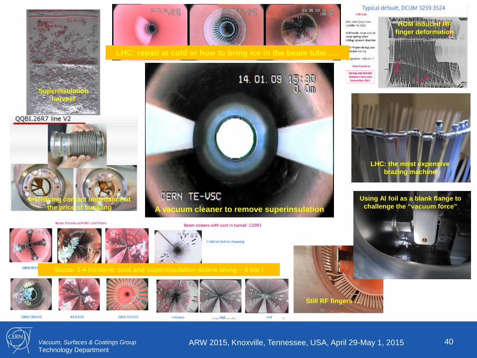
LHC: the most expensive brazing machine
LHC: repair at cold or how to bring ice in the beam tube ….
Superinsulation harvest
Increasing contact impedance at the price of buckling
Sector 3-4 incident: soot and superinsulation debris along ~ 6 km !
Using Al foil as a blank flange to challenge the “vacuum force”
Still RF fingers …
HOM induced RF finger deformation
A vacuum cleaner to remove superinsulation

Vacuum, Surfaces & Coatings Group Technology Department
41 ARW 2015, Knoxville, Tennessee, USA, April 29-May 1, 2015
Back up slides

Vacuum, Surfaces & Coatings Group Technology Department
42 ARW 2015, Knoxville, Tennessee, USA, April 29-May 1, 2015
Operation: Solenoids, a non-base line system
• Using expertise to solve unexpected issues: electron cloud with 150 ns bunch spacing (in common beam pipes) !
• Using creativity to reduce background in the experiments:
wrapping solenoids to increase the amount of anti-multipactor treated beam pipe length from 10 to 11 % ….

Vacuum, Surfaces & Coatings Group Technology Department 43
Arc Beam Vacuum Consolidation • Following sector 3-4 incident in September 2009 • ~ 850 rupture disk installation at each arc’s quadrupole (SSS) to mitigate bellows buckling in case of he inrush • Protective half-shells in case of arcing
Protective half-shells for cryomagnet interconnections
Courtesy C. Garion
ARW 2015, Knoxville, Tennessee, USA, April 29-May 1, 2015
Protection of the system against co-lateral damaged
ARW 2015, Knoxville, Tennessee, USA, April 29-May 1, 2015 44