Embed Size (px)
Citation preview

vacuum pump98074 1.2 cFm
98076 2.5 cFm
Set up and Operating inStructiOnS
model 98074
Diagrams within this manual may not be drawn proportionally.Due to continuing improvements, actual product may differ slightly from the product described herein.
distributed exclusively by Harbor Freight tools®.3491 Mission Oaks Blvd., Camarillo, CA 93011
visit our website at: http://www.harborfreight.com
read this material before using this product. Failure to do so can result in serious injury. Save tHiS manual.
Copyright© 2008 by Harbor Freight Tools®. All rights reserved. No portion of this manual or any artwork contained herein may be reproduced in any shape or form without the express written consent of Harbor Freight Tools.
For technical questions or replacement parts, please call 1-800-444-3353.
Warningto prevent explosion, serious injury, and
death:Service of air conditioning systems must •be done only by trained and experienced techniciantoavoidoverfilling.Technicians opening refrigeration circuit •in automotive air conditioning systems MUSTbecertifiedinrefrigerantrecoveryand recycling procedures in compliance with section 609 of Clean Air Act Amendments of 1990. For additional information regarding ozone depletion and air conditioning service regulations, visit EPA’s website: www.epa.gov/ozone
®
Page 298074 & 98076 For technical questions, please call 1-800-444-3353.
Save tHiS manualKeep this manual for the safety warn-
ings and precautions, assembly, operat-ing, inspection, maintenance and cleaning procedures. Write the product’s serial number in the back of the manual near the assembly diagram (or month and year of purchase if product has no number). Keep this manual and the receipt in a safe and dry place for future reference.
impOrtant SaFetY inFOrmatiOn
in this manual, on the labeling, and all other information provided with this product:
this is the safety alert symbol. it is used to alert you to potential personal injury hazards. Obey all safety messages that follow this symbol to avoid possible injury or death.
danger indicates a hazardous
situation which, if not avoided, will result in death or serious injury.
Warning indicates a
hazardous situation which, if not avoided, could result in death or serious injury.
cautiOn, used with the safety
alert symbol, indicates a hazardous situation which, if not avoided, could result in minor or moderate injury.
nOtice is used to address practices
not related to personal injury.
cautiOn, without the safety alert
symbol, is used to address practices not related to personal injury.
general pneumatic & power tool Safety Warnings
Warning read all safety warnings and instructions. Failure to follow the warnings and instructions may result in electric shock, fire and/or serious injury. Save all warnings and instructions for future reference. The term ″power tool″ in the warnings refers to your (corded), pneumatic power tool.
Work area safety1. Keep work area clean and well lit. a. Cluttered or dark areas invite acci-dents.never use this vacuum pump to b. vent refrigerants into the air. It is il-legal to do so, harmful to the environ-ment and poses a serious health risk.do not operate power tools in c. explosive atmospheres, such as in the presence of flammable liquids, gases or dust. Power tools create sparks which may ignite the dust or fumes.Keep children and bystanders d. away while operating a power tool. Distractions can cause you to lose control.
electrical safety2. power tool plugs must match the a. outlet. never modify the plug in any way. do not use any adapter plugs with grounded power tools.
Page 398074 & 98076 For technical questions, please call 1-800-444-3353.
Unmodified plugs and matching out-lets will reduce risk of electric shock. nOte: this vacuum pump has a 3-prong grounded plug.do not expose this vacuum pump b. to rain or wet conditions. Use in DRY locations only. do not abuse the cord. never use c. the cord for carrying, pulling or unplugging the power tool. Keep cord away from heat, oil, sharp edges or moving parts. Damaged or entangled cords increase the risk of electric shock.When operating this vacuum pump d. outdoors, use an extension cord suitable for outdoor use. Use of a cord suitable for outdoor use reduces the risk of electric shock.
personal safety3. Stay alert, watch what you are do-a. ing and use common sense when operating this vacuum pump. do not use while you are tired or un-der the influence of drugs, alcohol or medication. A moment of inatten-tion while operating power tools may result in serious personal injury.use safety equipment. always b. wear eye protection. Safety equip-ment such as dust mask, non-skid safety shoes, hard hat, or hearing protection used for appropriate condi-tions will reduce personal injuries.
power tool use and care4. do not use this vacuum pump if a. the switch does not turn it on and off. Any tool that cannot be con-trolled with the switch is dangerous and must be repaired.
disconnect the plug from the b. power source before storing power tool. Such preventive safety mea-sures reduce the risk of starting the Vacuum Pump accidently. Store this vacuum pump out of the c. reach of children and do not allow persons unfamiliar with this vacu-um pump or these instructions to operate. Power tools are dangerous in the hands of untrained users.maintain power tools. check for d. any condition that may affect the vacuum pump’s operation. if dam-aged, have it repaired before use. Many accidents are caused by poorly maintained power tools.use the vacuum pump in accor-e. dance with these instructions, taking into account the working conditions and the work to be per-formed. Use of this Vacuum Pump for operations different from those intended could result in a hazardous situation.Have your vacuum pump serviced f. by a qualified repair person. This will ensure that the safety of the Vacuum Pump is maintained.
Specific Safety WarningsAvoidoverfilling.Donotserviceair1. conditioning systems improperly.
Read entire manual before set up 2. and/or use.
Wear ANSI-approved safety goggles 3. during set up and/or use.
Certificationisrequiredbylawfor4. technicians opening refrigeration circuit.

Page 498074 & 98076 For technical questions, please call 1-800-444-3353.
Use in DRY locations only.5.
DO NOT cover this unit. This Vacu-6. um pump gets very hot when in use. Do not use near combustibles and let the unit cool down completely after using, and/or before moving or stor-age.
Maintain labels and nameplates on 7. the tool. These carry important safety information. If unreadable or miss-ing, contact Harbor Freight Tools for a replacement.
Do not leave this Vacuum Pump 8. unattended when it is plugged into an electrical outlet. Turn off the Pump and unplug it from its electrical outlet before leaving.
This product is not a toy. Keep it out 9. of reach of children.
People with pacemakers should 10. consult their physician(s) before use. Electromagneticfieldsincloseprox-imity to heart pacemaker could cause pacemaker interference or pacemak-er failure. In addition, people with pacemakers should: •Avoidoperatingalone. •Donotusewithpowerswitchlockedon. •Properlymaintainandinspecttoavoid electrical shock. •Anypowercordmustbeproperlygrounded. Ground Fault Circuit Inter-rupter (GFCI) should also be imple-mented – it prevents sustained elec-trical shock.
Warning: the brass compo-11. nents of this product contain lead, a chemical known to the state of california to cause birth defects (or other reproductive harm).
(california Health & Safety code § 25249.5 et seq.)
The warnings, precautions, and in-12. structions discussed in this instruction manual cannot cover all possible con-ditions and situations that may occur. It must be understood by the operator that common sense and caution are factors which cannot be built into this product, but must be supplied by the operator.
Save tHeSe inStructiOnS.
grOunding tO prevent
electric SHOcK and deatH FrOm incOrrect grOunding Wire cOnnectiOn: Check with a qualified electrician if you are in doubt as to whether the outlet is properly grounded. do not modify the power cord plug provided with the tool. never remove the grounding prong from the plug. do not use the tool if the power cord or plug is damaged. if damaged, have it repaired by a service facility before use. if the plug will not fit the outlet, have a proper outlet installed by a qualified electrician.

Page 598074 & 98076 For technical questions, please call 1-800-444-3353.
grounded tools: tools with three prong plugs
3-prong plug and Outlet
1. Tools marked with “Grounding Re-quired”haveathreewirecordandthree prong grounding plug. The plug must be connected to a properly grounded outlet. If the tool should electrically malfunction or break down, grounding provides a low resistance path to carry electricity away from the user, reducing the risk of electric shock. (See 3-prong plug and Outlet.)
The grounding prong in the plug is 2. connected through the green wire in-side the cord to the grounding system in the tool. The green wire in the cord must be the only wire connected to the tool’s grounding system and must never be attached to an electrically “live”terminal.(See 3-prong plug and Outlet.)
The tool must be plugged into an 3. appropriate outlet, properly installed and grounded in accordance with all codes and ordinances. The plug and outlet should look like those in the preceding illustration. (See 3-prong plug and Outlet.)
nOte: this vacuum pump comes 4. with a 3-prong plug attached to its power cord.
double insulated tools: tools with two prong plugs
Outlets for 2-prong plug
1. Toolsmarked“DoubleInsulated”donotrequiregrounding.Theyhavea special double insulation system whichsatisfiesOSHArequirementsand complies with the applicable standards of Underwriters Labora-tories, Inc., the Canadian Standard Association, and the National Electri-cal Code. (See Outlets for 2-prong plug.)
Double insulated tools may be used 2. in either of the 120 volt outlets shown in the preceding illustration. (See Outlets for 2-prong plug.)
extension cordsGrounded1. toolsrequireathreewireextension cord. Double Insulated tools can use either a two or three wire extension cord.
As the distance from the supply outlet 2. increases, you must use a heavier gauge extension cord. Using exten-sioncordswithinadequatelysizedwire causes a serious drop in voltage, resulting in loss of power and pos-sible tool damage. (See table a.) The smaller the gauge number of the wire, the greater the capacity of the cord. For ex-

Page 698074 & 98076 For technical questions, please call 1-800-444-3353.
ample, a 14 gauge cord can carry a higher current than a 16 gauge cord. (See table a.)
When using more than one exten-3. sion cord to make up the total length, make sure each cord contains at leasttheminimumwiresizerequired.(See table a.)
If you are using one extension cord 4. for more than one tool, add the nameplate amperes and use the sum todeterminetherequiredminimumcord size. (See table a.)
If you are using an extension cord 5. outdoors, make sure it is marked with thesuffix“W-A”(“W”inCanada)toindicate it is acceptable for outdoor use.
Make sure the extension cord is prop-6. erly wired and in good electrical con-dition. Always replace a damaged extension cord or have it repaired by aqualifiedelectricianbeforeusingit.
Protect the extension cords from 7. sharp objects, excessive heat, and damp or wet areas.
recOmmended minimum Wire gauge FOr eXtenSiOn cOrdS*
(120/240 vOlt)
nameplateampereS(at full load)
eXtenSiOn cOrd lengtH
25’
50’
75’
100’
150’
0 – 2.0 18 18 18 18 162.1 – 3.4 18 18 18 16 143.5 – 5.0 18 18 16 14 125.1 – 7.0 18 16 14 12 12
7.1 – 12.0 18 14 12 10 -12.1 – 16.0 14 12 10 - -16.1 – 20.0 12 10 - - -
taBle a* Based on limiting the line voltage drop to five volts at 150% of the rated amperes.
Symbology
Double Insulated
Canadian Standards Association
Underwriters Laboratories, Inc.
v~ Volts Alternating Current
a Amperes
n0 xxxx/min. No Load Revolutions per Minute (RPM)
Page 798074 & 98076 For technical questions, please call 1-800-444-3353.
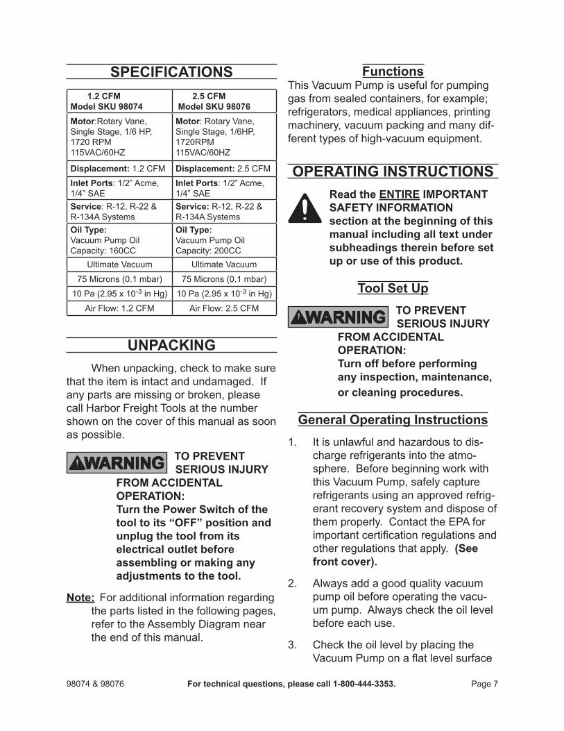
SpeciFicatiOnS 1.2 cFm model SKu 98074
2.5 cFm model SKu 98076
motor:Rotary Vane, Single Stage, 1/6 HP, 1720 RPM115VAC/60HZ
motor: Rotary Vane,Single Stage, 1/6HP,1720RPM115VAC/60HZ
displacement: 1.2 CFM displacement: 2.5 CFM
inlet ports:1/2”Acme,1/4”SAE
inlet ports:1/2”Acme,1/4”SAE
Service: R-12, R-22 & R-134A Systems
Service: R-12, R-22 & R-134A Systems
Oil type:Vacuum Pump OilCapacity: 160CC
Oil type:Vacuum Pump Oil Capacity: 200CC
Ultimate Vacuum Ultimate Vacuum
75 Microns (0.1 mbar) 75 Microns (0.1 mbar)
10 Pa (2.95 x 10⁻³ in Hg) 10 Pa (2.95 x 10⁻³ in Hg)
Air Flow: 1.2 CFM Air Flow: 2.5 CFM
unpacKingWhen unpacking, check to make sure
that the item is intact and undamaged. If any parts are missing or broken, please call Harbor Freight Tools at the number shown on the cover of this manual as soon as possible.
tO prevent SeriOuS injurY
FrOm accidental OperatiOn: turn the power Switch of the tool to its “OFF” position and unplug the tool from its electrical outlet before assembling or making any adjustments to the tool.
note: For additional information regarding the parts listed in the following pages, refer to the Assembly Diagram near the end of this manual.
FunctionsThis Vacuum Pump is useful for pumping gas from sealed containers, for example; refrigerators, medical appliances, printing machinery, vacuum packing and many dif-ferenttypesofhigh-vacuumequipment.
Operating inStructiOnS read the entire impOrtant
SaFetY inFOrmatiOn section at the beginning of this manual including all text under subheadings therein before set up or use of this product.
tool Set up tO prevent
SeriOuS injurY FrOm accidental OperatiOn: turn off before performing any inspection, maintenance, or cleaning procedures.
general Operating instructionsIt is unlawful and hazardous to dis-1. charge refrigerants into the atmo-sphere. Before beginning work with this Vacuum Pump, safely capture refrigerants using an approved refrig-erant recovery system and dispose of them properly. Contact the EPA for importantcertificationregulationsandother regulations that apply. (See front cover).
Alwaysaddagoodqualityvacuum2. pump oil before operating the vacu-um pump. Always check the oil level before each use.
Check the oil level by placing the 3. VacuumPumponaflatlevelsurface
Page 898074 & 98076 For technical questions, please call 1-800-444-3353.
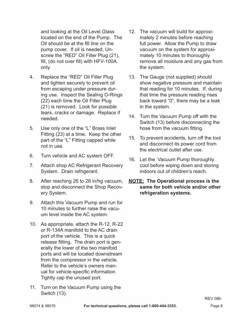
and looking at the Oil Level Glass located on the end of the Pump. The Oilshouldbeatthefilllineonthepump cover. If oil is needed, Un-screwthe“RED”OilFillerPlug(21),fill,(donotoverfill)withHFV-100Aonly.
Replacethe“RED”OilFillerPlug4. and tighten securely to prevent oil from escaping under pressure dur-ing use. Inspect the Sealing O-Rings (22) each time the Oil Filler Plug (21) is removed. Look for possible tears, cracks or damage. Replace if needed.
Useonlyoneofthe“L”BrassInlet5. Fitting (23) at a time. Keep the other partofthe“L”Fittingcappedwhilenot in use.
Turn vehicle and AC system OFF.6.
Attach shop AC Refrigerant Recovery 7. System. Drain refrigerant.
After reaching 26 to 28 in/hg vacuum, 8. stop and disconnect the Shop Recov-ery System.
Attach this Vacuum Pump and run for 9. 10 minutes to further raise the vacu-um level inside the AC system.
As appropriate, attach the R-12, R-22 10. or R-134A manifold to the AC drain portofthevehicle.Thisisaquickreleasefitting.Thedrainportisgen-erally the lower of the two manifold ports and will be located downstream from the compressor in the vehicle. Refer to the vehicle’s owners man-ualforvehicle-specificinformation.Tightly cap the unused port.
Turn on the Vacuum Pump using the 11. Switch (13).
The vacuum will build for approxi-12. mately 2 minutes before reaching full power. Allow the Pump to draw vacuum on the system for approxi-mately 10 minutes to thoroughly remove all moisture and any gas from the system.
The Gauge (not supplied) should 13. show negative pressure and maintain that reading for 10 minutes. If, during that time the pressure reading rises backtoward“0”,theremaybealeakin the system.
Turn the Vacuum Pump off with the 14. Switch (13) before disconnecting the hosefromthevacuumfitting.
To prevent accidents, turn off the tool 15. and disconnect its power cord from the electrical outlet after use.
Let the Vacuum Pump thoroughly 16. cool before wiping down and storing indoors out of children’s reach.
nOte: the Operational process is the same for both vehicle and/or other refrigeration systems.
REV 08h

Page 998074 & 98076 For technical questions, please call 1-800-444-3353.
maintenance and Servicing
Procedures not specifically explained in this manual must be performed only by a qualified technician.
tO prevent SeriOuS injurY
FrOm accidental OperatiOn: turn the power Switch of the tool to its “OFF” position and unplug the tool from its electrical outlet before performing any inspection, or cleaning procedures.
tO prevent SeriOuS injurY FrOm tOOl Failure: do not use damaged equipment. if abnormal noise or vibration occurs, have the problem corrected before further use.
cleaning, maintenance, and lubrication
BeFOre eacH uSe,1. inspect the general condition of the tool. Check for loose screws, cracked or broken parts, damaged electrical wiring, and any other condition that may affect its safe operation.
aFter uSe,2. clean external surfaces of the tool with clean cloth.
3. Warning! if the supply cord of this power tool is damaged, it must be replaced only by a qualified service technician.
pleaSe read tHe FOllOWing careFullY
THE MANUFACTURER AND/OR DISTRIBUTOR HAS PROVIDED THE PARTS LIST AND ASSEMBLY DIAGRAM IN THIS MANUAL AS A REFERENCE TOOL ONLY. NEITHER THE MANUFACTURER OR DISTRIBUTOR MAKES ANY REPRESENTATION OR WARRANTY OF ANY KIND TO THE BUYER THAT HE OR SHE IS qUALIFIED TO MAKE ANY REPAIRS TO THE PRODUCT, OR THAT HE OR SHE IS qUALIFIED TO REPLACE ANY PARTS OF THE PRODUCT. IN FACT, THE MANUFACTURER AND/OR DISTRIBUTOR ExPRESSLY STATES THAT ALL REPAIRS AND PARTS REPLACEMENTS SHOULD BE UNDERTAKEN BY CERTIFIED AND LICENSED TECHNICIANS, AND NOT BY THE BUYER. THE BUYER ASSUMES ALL RISK AND LIABILITY ARISING OUT OF HIS OR HER REPAIRS TO THE ORIGINAL PRODUCT OR REPLACEMENT PARTS THERETO, OR ARISING OUT OF HIS OR HER INSTALLATION OF REPLACEMENT PARTS THERETO.
Page 1098074 & 98076 For technical questions, please call 1-800-444-3353.
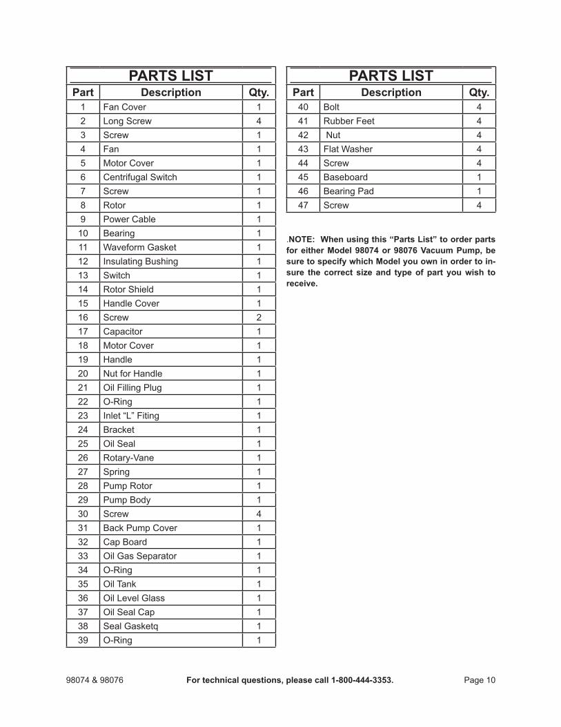
partS liStpart description Qty.
1 Fan Cover 12 Long Screw 43 Screw 14 Fan 15 Motor Cover 16 Centrifugal Switch 17 Screw 18 Rotor 19 Power Cable 1
10 Bearing 111 Waveform Gasket 112 Insulating Bushing 113 Switch 114 Rotor Shield 115 Handle Cover 116 Screw 217 Capacitor 118 Motor Cover 119 Handle 120 Nut for Handle 121 Oil Filling Plug 122 O-Ring 123 Inlet“L”Fiting 124 Bracket 125 Oil Seal 126 Rotary-Vane 127 Spring 128 Pump Rotor 129 Pump Body 130 Screw 431 Back Pump Cover 132 Cap Board 133 Oil Gas Separator 134 O-Ring 135 Oil Tank 136 Oil Level Glass 137 Oil Seal Cap 138 SealGasketq 139 O-Ring 1
partS liStpart description Qty.
40 Bolt 441 Rubber Feet 442 Nut 443 Flat Washer 444 Screw 445 Baseboard 146 Bearing Pad 147 Screw 4
.nOte: When using this “parts list” to order parts for either model 98074 or 98076 vacuum pump, be sure to specify which model you own in order to in-sure the correct size and type of part you wish to receive.
Page 1198074 & 98076 For technical questions, please call 1-800-444-3353.
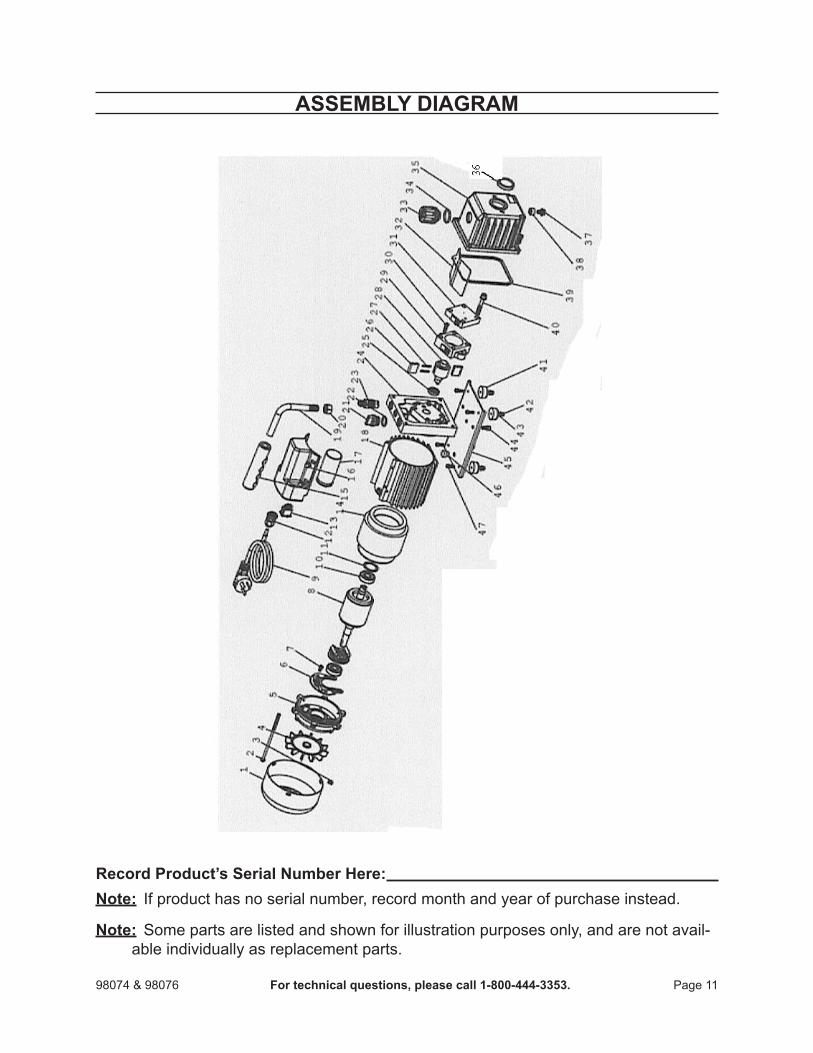
aSSemBlY diagram
record product’s Serial number Here: note: If product has no serial number, record month and year of purchase instead.
note: Some parts are listed and shown for illustration purposes only, and are not avail-able individually as replacement parts.

Page 1298074 & 98076 For technical questions, please call 1-800-444-3353.
limited 1 Year WarrantYHarbor Freight Tools Co. makes every effort to assure that its products meet high
qualityanddurabilitystandards,andwarrantstotheoriginalpurchaserthatthisproductis free from defects in materials and workmanship for the period of one year from the dateofpurchase(90daysifusedbyaprofessionalcontractororifusedasrentalequip-ment). This warranty does not apply to damage due directly or indirectly, to misuse, abuse, negligence or accidents, repairs or alterations outside our facilities, normal wear and tear, or to lack of maintenance. We shall in no event be liable for death, injuries topersonsorproperty,orforincidental,contingent,specialorconsequentialdamagesarising from the use of our product. Some states do not allow the exclusion or limitation ofincidentalorconsequentialdamages,sotheabovelimitationofexclusionmaynotap-ply to you. THIS WARRANTY IS ExPRESSLY IN LIEU OF ALL OTHER WARRANTIES, ExPRESS OR IMPLIED, INCLUDING THE WARRANTIES OF MERCHANTABILITY AND FITNESS.
To take advantage of this warranty, the product or part must be returned to us with transportation charges prepaid. Proof of purchase date and an explanation of the com-plaintmustaccompanythemerchandise.Ifourinspectionverifiesthedefect,wewillei-ther repair or replace the product at our election or we may elect to refund the purchase priceifwecannotreadilyandquicklyprovideyouwithareplacement.Wewillreturnre-paired products at our expense, but if we determine there is no defect, or that the defect resulted from causes not within the scope of our warranty, then you must bear the cost of returning the product.
Thiswarrantygivesyouspecificlegalrightsandyoumayalsohaveotherrightswhich vary from state to state.
3491 Mission Oaks Blvd. • PO Box 6009 • Camarillo, CA 93011 • (800) 444-3353