Embed Size (px)
Citation preview

VACUUM CLEANERSERVICE MANUAL
MODEL: V-C7050NT, V-C7050HTV-C7070CT, V-C7070CP
CAUTION
BEFORE SERVICING THE UNIT, READ THE “SAFETY PRECAUTIONS” IN THIS MANUAL.

2
CONTENTS
SAFETY PRECAUTIONS ......................................................................................................................... 3
CAUTIONS ................................................................................................................................................ 3
DESCRIPTION .......................................................................................................................................... 4
SPECIFICATIONS..................................................................................................................................... 4
DISASSEMBLY ......................................................................................................................................... 5
TROUBLE SHOOTING ..............................................................................................................................6
BLOCK DIAGRAM.....................................................................................................................................9
SCHEMATIC DIAGRAM ............................................................................................................................9
CIRCUIT DIAGRAM .................................................................................................................................. 9
EXPLODED VIEW ...................................................................................................................................13
REPLACEMENT PARTS LIST.................................................................................................................17
APPENDIX .............................................................................................................................................. 19
1. THE TYPE OF POWER CORD & PARTS NUMBER .................................................................................19
2. COLOR & PARTS NUMBER..................................................................................................................20
3. MOTOR & PWB ASSY PARTS NUMBER ................................................................................................20

3
BEFORE OPERATING THIS VACUUM CLEANER, READ THIS SERVICE MANUAL THOROUGHLY,AND OBSERVE EACH POINT CAREFULLY.
BEFORE ATTEMPTING TO SERVICE OR ADJUST ANY PART OF THE VACUUM CLEANER, DISCONNECTTHE ELECTRICAL POWER SUPPLY CORD FROM THE WALL OUTLET.
1. Motor filter(Air Cleaner)
1) This filter is reusable.
2) Never use the vacuum cleaner without filter.It may damage the motor.
3) When the light of body is on, wash the motor filterwith water and brush.
4) Even if the light is not on, wash the motor filter atleast once 6 months.
NOTE : Reusing of the motor filter.
Never wash the filter in a washing machine or in adishwasher.
Never use hot water for washing the filter.
Reuse the filter after drying it completely in theshade for a day.
Do not dry near fire or direct sunray.
2. Exhaust filter(Washable HEPA filter)
1) This filter is reusable HEPA filter.
2) For clean air, theis filter must be assembled.
3) Wash the exhaust filter with water once a year.
NOTE : Reusing of the exhaust filter.
Never wash the filter in a washing machine or in adishwasher.
Never use hot water for washing the filter.
Reuse the filter after drying it completely in theshade for a half day.
Do not dry near fire or direct sunray.
Do not brush the filter. This will cause permanentlydamage allowing dust to by-pass the filter.
3. Avoid suction such materials as :
1) Liquid or wet dust : Clogs the ventilation holes, reduces the suctionpower significantly and harms the motor.
2) Inflammable liquids such as benzene, alcohol or solvents.
3) Burning objects such as cigarette butts.
4) Bulky objects such as vinyl, paper etc.
5) Sharp objects such as needles, pins, metal, glass particles etc.
4. Attachments
• Nozzle : For cleaning wooden floor, the room floor and carpet.
• Dusting Brush and Crevice Tool:For cleaning any crevice, inside corners of windowframes.For delicate vacuuming of fabrics on the furniture,curtains, etc.
• Upholstery Nozzle : For vacuuming the dust on theupholstery.
However, do not use the crevice tool more than 20minutes because it may cause harm to the motor.
5. Close supervision is necessary when this vacuum cleaner is used by or near children. Children’s carelessness may cause damage to the cleaner or injure persons.
6. Air exhausted from the vacuum cleaner isnormally warm. But if extraordinarily hot air isexhausted, check if the telescopic tube, hose orclean filter is clogged or not.
7. Electric shock could occur if used outdoors or on wet surfaces.
1. Motor exchange
1) Separate the Body Cover and Body Base byunfastening the screws.
2) After disconnecting the lead wires, replace the oldmotor with a new one.
2. In case of exchanging other parts. refer to theexploded view.
SAFETY PRECAUTIONS
CAUTIONS

4
DESCRIPTION
SPECIFICATIONS
TelesscopicPipe ASS'Y
Flexible Hose ASS'Y
ATTACHMENTS
Power Cord
Filter Cover
Nozzle ASS'Y
Cord Reel Button
Dust Tank
UPHOLSTERY NOZZLEDUSTING BRUSH & CREVICE TOOL BRUSH ASS'Y
This specifications are subject to change according to the buyer’s request.
• MODEL : REFER TO THE COVER PAGE• POWER SOURCE : ON RATING PLATE• POWER CONSUMPTION : ON RATING PLATE• POWER CONTROL :
- MAIN : SLIDE CONTROL (F/HOSE)(V-C7050HT)MICOM CONTROL (F/HOSE)(V-C7070CT)PUSH ON/OFF(BODY)(V-C7050NT)
- SUB : VACUUM POWER ADJUSTMENT BYSLIDE KNOB (V-C7050NT)
• CORD LENGTH : 7m• HOSE LENGTH : 1.8m• NET WEIGHT : 5.3Kg• PACKING WEIGHT : 8.4Kg• NET DIMENSION : 290 × 443 × 311(W × D × H)mm• PACKING DIMENSION : 330 × 567 × 385(W × D × H)mm• ATTACHMENTS
HOSE ................................................................ 1EATELESCOPIC PIPE ASSY ................................ 1EANOZZLE ASSY.................................................. 1EADUSTING BRUSH & CREVICE TOOL.............. 1EAUPHOLSTERY NOZZLE ................................... 1EABRUSH ASS'Y................................................... 1EA
CANISTER

5
• Almost all the parts of this vacuum cleaner can be disassembled with a screw driver and each connectingcomponent easily fits each other.Disassemble one by one referring to the exploded view.
• If possible, don’t disassemble except for thenecessary parts. It is not necessary to disassemblethe parts that are not detailed in the exploded view.
DISASSEMBLYNOTE: Before attempting to service or adjust any part of the vacuum cleaner, disconnect the electrical
power supply cord from the wall outlet.
Motor Ass'y
Cord Reel Ass'y
1. Body Cover Assembly Replacement1) Remove the dust tank from the set.
2) Remove the four screws fastening the body base.
2) Bring out the motor and disconnect the lead wiresfrom it.
3. Cord Reel Assembly Replacement1) Remove the cord reel cover by unfastening the
screw.
2) Lift the cord reel assembly from the body base.
3) Disassemble the filter cover, widening the both offilter cover, and then pull out the lead wires fromthe push switch.
2. Motor Assembly Replacement1) Unhook the motor housing cover in the direction
of the arrow.

6
TROUBLE SHOOTING1. SWITCH ON BUT MOTOR DOES NOT TURN
2. SWITCH ON, MOTOR DOES NOT TURN BUT BUZZES
CHECKING
CHECK THE POWERSOURCE
The fuse is melt down in thecoverknife switch. Exchange the fuse.
Poor plug insertion Insert again.
Power cord cut Repair or exchange.
Interior lead wire cut Exchange the lead wire.
Motor(stator, armature) coil cut or damaged.
Exchange the motor.
Poor contact carbon brushdefaced.
Exchange or repair the motor.
Poor switch contact point Exchange the switch.
Motor armature cut. Exchange the motor.
Ball bearing defacement Exchange the motor.
Impeller hindrance(Caused by foreign matters)
Remove the foreign matters.
CAUSE SOLUTION

7
3. SWITCH OFF BUT MOTOR TURNS
4. WEAK SUCTION POWER
Carbon brush defacedExchange the carbon brush or the motor.
Motor armature cut Exchange the motor.
Foreign matters attached tothe impeller
Remove the foreign matters.
Low voltageInquire to the power utility company.
Hose and extension wandsare clogged with foreign matters.
Remove the foreign mattersin the hose or extensionwands.
The slide knob on the handle isopened or the control knob islocated on weak position.
Close the slide knob by sliding it.Regulate the knob.
The motor filter is clogged. Clean the motor filter.
The exhaust filter is clogged. Exchange the exhaust filter.
Poor connection Repair.
Poor switch
Low rotation speed
Motor turns normally,but suction power is weak.
Exchange the switch.

8
5. VIBRATION NOISES
6. RADIO, TV RECEPTION DISTURBANCE
7. IMPROPER TUBE OR NOZZLE CONNECTION
Loose parts Secure firmly.
Unbalanced motor assembly Exchange or repair the motor.
Foreign matters are attachedto the impeller.
Remove the foreign matters.
Poor carbon brush rectification Exchange the motor.
Poor cord, lead wire Exchange cord, lead wire.
Poor rectification of carbon brush
Exchange the motor.
Poor electric connector orreceiver
Repair the electric connectoror receiver.
Poor capacitor Exchange the capacitor.
Bent connection parts Exchange the parts.
Poor connection(Caused by foreign matters)
Remove the foreign mattersand reconnect.
Armature is cut or foreignmatters attached.
Exchange the motorRemove foreign matters.
9
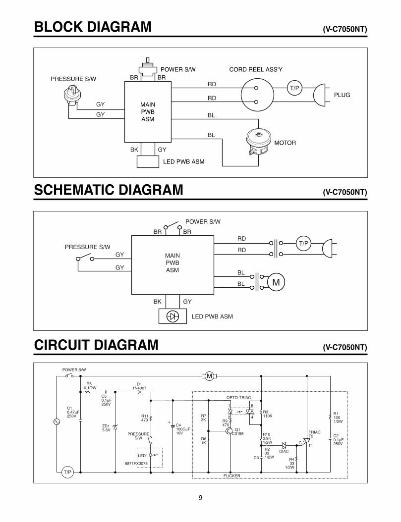
BLOCK DIAGRAM (V-C7050NT)
SCHEMATIC DIAGRAM (V-C7050NT)
PRESSURE S/W
POWER S/W CORD REEL ASS'Y
LED PWB ASM
MOTOR
PLUG
MAINPWBASM
GY
GY
BK GY
RDBR BR
RD
BL
BL
T/P
M
C10.47µF250V
C50.1µF250V
C20.1µF250V
R11001/2W
C4100GµF16V
R610,1/2W
D11N4007
Q1C3198
FLICKER
C3
OPTO-TRIAC
1 6
2 4
PRESSURES/W
LED1
6871FX3078
POWER S/W
ZD15.6V
R11470
R73K R9
470
R3110K
R103.9K1/2W
R2331/2W
R433
1/2W
DIAC
T1G
TRIACT2
R81K
+
T/P
POWER S/W
PRESSURE S/W
BR
GY
GY
BR
BK GY
RD
RD
BL
BL
LED PWB ASM
M
MAINPWBASM
T/P
CIRCUIT DIAGRAM (V-C7050NT)

10
BLOCK DIAGRAM (V-C7050HT)
SCHEMATIC DIAGRAM (V-C7050HT)
PRESSURE S/W
SLIDE VOLUME
HOSE
POWER S/WLED PWB ASM
SUBPWBASM
MAINPWBASM
BR BR
RD
RD
BL
BL
BK
GY
GY
GY
T/P
POWER S/W
MOTOR
BD1
C10.47uF/AC250
R1470K1/2W
R10-1470K1/2W
R161.5K
R125.6K
R131K
C42200uF
16V Q3C3198
C30.47uF/100V
D61N4002
R11390
IC2
R14100
R9100
R1512K
S/VOLR5100
D51N4148
Q2A1015
Q1C3198
R713K
R618K
IC1
R411K
R3470
1/2W
C20.1uF630V
T2
T1G
R1100
1/2W
R2330
1/2W
VR/20K
R8
1K
LED1
M
+
TRANSTRANS
PRESSURES/WPRESSURES/W
PHOTO-TRIACPHOTO-TRIAC PHOTO-TRIACPHOTO-TRIAC
T/P
LED PWB ASM
SLIDE VOLUME
PRESSURE S/W
POWER S/W
SUBPWBASM
MAINPWBASM
GY
BR BR
GY M
T/P
CIRCUIT DIAGRAM (V-C7050HT)

11
BLOCK DIAGRAM (V-C7070CT)
DISPLAYPWB ASM
SUBPWBASM
PRESSURES/W
DUSTSENSORPWB ASM
HOSEPWBASM
DUSTSESM
PWB ASM
MAINPWBASM
RD
RD
BL
BLT/P

12
CIRCUIT DIAGRAM (V-C7070CT)
G
M
+
ST
-7L
EL-
7L
+
15 30 20
AV
ref
CST
4.0M
X-TA
L
191M
Xou
t
VS
S
18
R8
Xin
VD
D
R56
R2
330
470
1/2W
BD
1
DF
01M
R6
IC2
KIA
78L0
5P
0.1u
FC
5
O
C4
0.1u
F10
00uF
C3
I
1N40
02
D1
10K
1uF
KRC
107M
Q3
470
R4
100K
R5
2
TLP
762J
F4
1IC
16
R3
1/2W
250V
0.47
uFC
1
TR
AN
S
0.1u
F
100
R163
0V
T1
T2
GSM
12JZ
47T
RIA
CC
2
13
GMS81504(T) R40
/INT
0
RE
SE
T
KRC
107M
BZ
470
R12
1KR11
R55
/BU
Z14
Q2
MIC
OM
MO
TO
R
16V
RB
D
R9
470K
0.1u
FC
6
Q1
C31
98
R7
4.7K
0.01
uFC
7
IC3
179
1% 1%
+5V
+12
V
7042
25V
C13
0.1u
F
470K
1/2
WR
10R
10-1
470K
1/2
W
1/2W
R65
/AN
5
R64
/AN
4
CN
6
0.01
uF25
V
21
CN
7
0.1u
F
10K
R24
C12
C10
10
10K
R23
11
R16
CN
5
0.1u
FC
20
30K
1%2KR17
R24
S/W
4
R22
R23
S/W
2
S/W
3
4.3K
2.2K
R21
S/W
111
K
1.2K
10K
R25
R41
12
KRC
107M
R44
6
Q4
KRC
107M
R45
5
Q5
KRC
107M
R46
4
Q6
2.7KR13
1.5KR14
1.0KR15
1 2 3 4
CN
1
PR
ES
SU
RE
S/W
CN
2
KRC
107M
R04
27
Q14
10R34
KRC
107M
Q13
10R33
KRC
107M
Q12
10R32
KRC
107M
Q11
10R13
KRC
107M
Q15
10R31
KRC
107M
Q16
10R36
KRC
107M
Q17
1R
37
R05
26
R06
25
R07
24
R03
28
R02
29
R01
1
A
CN
8
BC
DE
FG
16V
C8

13
EXPLODED VIEW
152313
140561
249701
135507
146871
139204
252301149741
146611
145103
333002
748382
135506
333003
139202
146811
239402
130401
148201
144411
149308
750063
235505
252311
235504
236601

14
150061
135509
135510
335503
136501
168711
168711
235501
140261
349701
135508
166012
249011
452002
250201
249701
168711
268712
268712
168711
135510
135509
268711
440361
468011
452003
435506
440361
468712
468711
452003
435506
V-C7070CT/CP
V-C7050NT
V-C7050NT/HT V-C7070CT/CP
V-C7050NT
V-C7050NT
V-C7050NT/HT V-C7070CT
268712

15
452151
652012
436501
449321
552491
652031
652032
652481
452151
449321
435501
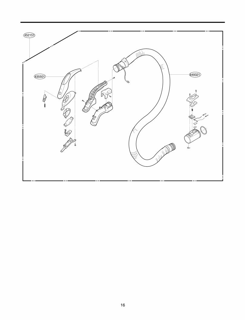
16
452151
449321435501
17
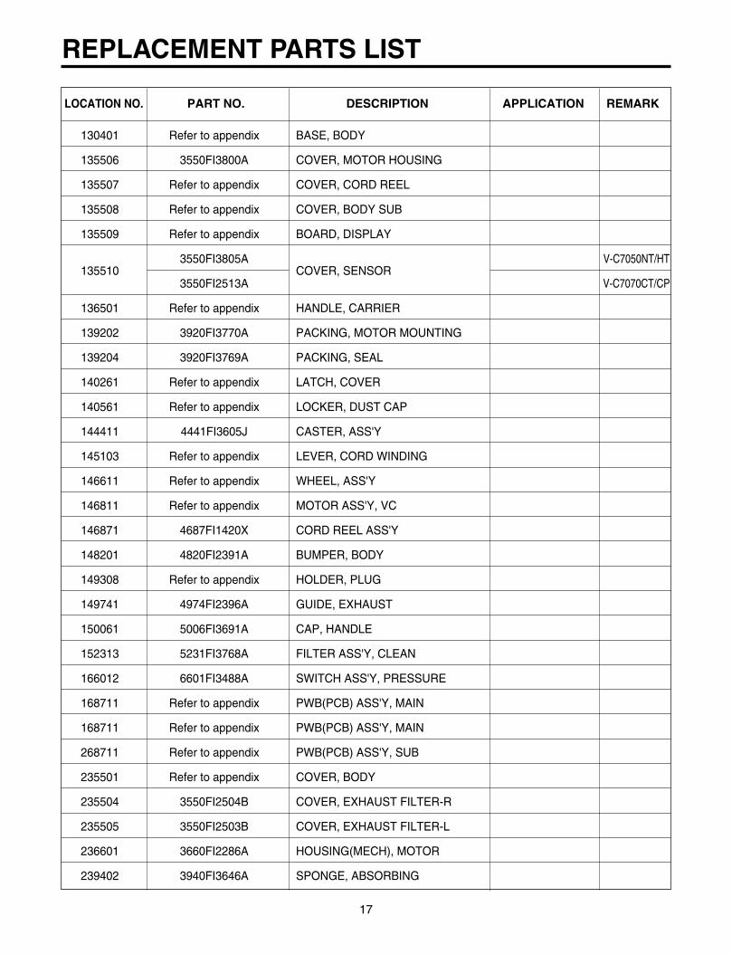
REPLACEMENT PARTS LIST
130401 Refer to appendix BASE, BODY
135506 3550FI3800A COVER, MOTOR HOUSING
135507 Refer to appendix COVER, CORD REEL
135508 Refer to appendix COVER, BODY SUB
135509 Refer to appendix BOARD, DISPLAY
1355103550FI3805A
COVER, SENSORV-C7050NT/HT
3550FI2513A V-C7070CT/CP
136501 Refer to appendix HANDLE, CARRIER
139202 3920FI3770A PACKING, MOTOR MOUNTING
139204 3920FI3769A PACKING, SEAL
140261 Refer to appendix LATCH, COVER
140561 Refer to appendix LOCKER, DUST CAP
144411 4441FI3605J CASTER, ASS'Y
145103 Refer to appendix LEVER, CORD WINDING
146611 Refer to appendix WHEEL, ASS'Y
146811 Refer to appendix MOTOR ASS'Y, VC
146871 4687FI1420X CORD REEL ASS'Y
148201 4820FI2391A BUMPER, BODY
149308 Refer to appendix HOLDER, PLUG
149741 4974FI2396A GUIDE, EXHAUST
150061 5006FI3691A CAP, HANDLE
152313 5231FI3768A FILTER ASS'Y, CLEAN
166012 6601FI3488A SWITCH ASS'Y, PRESSURE
168711 Refer to appendix PWB(PCB) ASS'Y, MAIN
168711 Refer to appendix PWB(PCB) ASS'Y, MAIN
268711 Refer to appendix PWB(PCB) ASS'Y, SUB
235501 Refer to appendix COVER, BODY
235504 3550FI2504B COVER, EXHAUST FILTER-R
235505 3550FI2503B COVER, EXHAUST FILTER-L
236601 3660FI2286A HOUSING(MECH), MOTOR
239402 3940FI3646A SPONGE, ABSORBING
LOCATION NO. PART NO. DESCRIPTION APPLICATION REMARK

18
249011 4901FI3435B DAMPER, ASS'Y
249701 4970FI4724A SPRING, BUTTON V-C7050NT
250201 Refer to appendix BUTTON, POWER SWITCH
252301 5231FI3758C FILTER ASS'Y, CLEAN
252311 5231FI3767A FILTER ASS'Y, EXHAUST
2687126871FX3078A
PWB(PCB) ASS'Y, DISPLAYV-C7050NT/HT
6871XF3080A V-C7070CT/CP
333002 Refer to appendix PLATE, COVER(L)
333003 Refer to appendix PLATE, COVER(R)
335503 Refer to appendix COVER ACCESSARY
349701 Refer to appendix SPRING, LATCH
435501 3550FI1553A COVER, GRIP HANDLE
435506 3550FI3802A COVER, TERMINAL
436501 3650FI1485C HANDLE, GRIP
440361 4036FI3603A SEAL, PIPE
4493214932FI2364D
CONNECTOR(MECH), HOSE ASMV-C7050NT/HT
4932FI2723A V-C7070CT/CP
452002 5200FI2480A PIPE, CONNECTOR
452003 Refer to appendix PIPE, CONNECTOR-H
452151 5215FI1315E HOSE ASS'Y, FLEXIBLE
468711 6871FX3077A PWB ASS'Y SENSOR V-C7070CT/CP
468712 6871FX3077B PWB ASS'Y SENSOR V-C7070CT/CP
552491 5249FI1399C NOZZLE ASS'Y, FLOOR
652012 Refer to appendix PIPE ASS'Y, TELESCOPIC
652031 5203FI2069A BRUSH ASS'Y, DUST
652032 5203FI3744A BRUSH ASS'Y, FILTER-CLEANER
652481 5248FI3454A NOZZLE, UPHOLSTERY
748382 Refer to appendix TANK, DUST
750063 Refer to appendix CAP, DUST
LOCATION NO. PART NO. DESCRIPTION APPLICATION REMARK

19
APPENDIX
1. THE TYPE OF POWER CORD & PARTS NUMBER
TYPE
A-1
S-1
C-2
C-1
B-3
4687FI1420X
TYPE OF PLUG CORD REEL ASSY P/NO.(L/NO.146871)
17
12.7
19
19
4.8
19
19
4
17
6.3
Color identificationof fuse
Brown
Yellow
Blue
13A
5A
3A

20
2. COLOR & PARTS NUMBER
3. MOTOR & PWB ASS’Y PARTS NUMBER
PART NO. REMARKLOCATION NO.
DESCRIPTION
4681FI2451A VMC400E5, 230V/50Hz V-C7030NT
4681FI12457A VMC420E5, 230V/50Hz V-C7040TN/C7045HT
4681FI2456B VMC460E5, 220~230V/50Hz V-C7050NT/HT
4681FI2456D VMC460E8, 220~230V/50Hz V-C7070CT/CP146811 MOTOR ASS'Y, VC
4681FI2456E VMC460E9, 240V/50Hz V-C7070CT/CP
240V/50Hz
110V/60Hz
120V/60Hz
PART NO. REMARKLOCATION NO.
DESCRIPTION
168711 PWB(PCB) ASS'Y, MAIN 6871FX2136A V-C7050NT168711 PWB(PCB) ASS'Y, MAIN 6871FX2141A V-C7050HT/V-C7070CT
268711 PWB(PCB) ASS'Y, SUB6871FX2142A V-C7050HT6871FX2145A V-C7070CT
LOCATION NO. DESCFIPTION LIGHT SILVER NOBLE DEEP BLUE NOBLE RED YELLOW GREEN DEEP BLACK REMARK130401 BASE BODY 3040FI1487B 3040FI1487B 3040FI1487E135507 COVER, CORD REEL 3550FI1558B 3550FI1558B 3550FI1558E135508 COVER, BODY SUB 3550FI1561B 3550FI1561B 3550FI1561E135509 BOARD, DISPLAY 3500FI2240B 3500F22240B 3500F22243E
136501 HANDLE, CARRIER3650FI1486B 3650FI1486B V-C7050NT/HT3651FI1309A 3651FI1309C V-C7070CT/CP
140261 LATCH, COVER 4026FI3669B 4026FI3669A 4026FI3669D140561 LOCKER, DUST CAP 4056FI3648D 4056FI3648D 4056FI3648D145103 LEVER, CORD WINDING 4510FI3598B 4510FI3598B 4510FI3598E146611 WHEEL, ASS'Y 4661FI3613B 4661FI3613B 4661FI3613E148201 BUMPER, BODY 4820FI2391B 4820FI2391B 4820FI2391E149308 HOLDER, PLUG 4930FI2448B 4930FI2448B 4930FI2448E235501 COVER, BODY 3550FI1560B 3550F21560B 3550FI1560F250201 BUTTON, POWER SWITCH 5020FI3771B 5020FI3771A 5020FI3771D333002 PLATE, COVER(L) 3300FI3683B 3300FI3683B 3300FI3683E333003 PLATE, COVER(R) 3300FI3684B 3300FI3684B 3300FI3684E335503 COVER, ACCESSARY 3550FI1559B 3550FI1559B 3550FI1559D435501 COVER, GRIP HANDLE 3550FI1553Q 3550FI1553Y V-C7070CT/CP452003 PIPE, CONNECTOR-H 5200FI1215B 5200FI1215B 5200FI1215K
452151 HOSE ASS'Y, FLEXIBLE5215FI1319D 5215FI1319E V-C7070CT5215FI1315E 5215FI1315E V-C7050NT5215FI1320B 5215FI1320C 5215FI1320K V-C7050HT
652012 PIPE ASS'Y TELESCOPIC5201FI1004A 5201FI2446D5210FI2446D
748382 TANK, DUST 4838FI1397B 4838F21397B 4838FI1397D750063 CAP, DUST 5006FI1327B 5006F21327B 5006FI1327E

21
MEMO

22
MEMO

P/No. : 3828FI3816ADecember, 2001Printed in Korea