Embed Size (px)
Citation preview

vacon 100 flow ac drives
application manual
®


PREFACEDocument ID: DPD01083D
Date: 15.10.2014
Software version: FW0159V010
ABOUT THIS MANUAL
This manual is copyright of Vacon Plc. All Rights Reserved.
In this manual, you can read about the functions of the Vacon® AC drive and how to use thedrive. The manual has the same structure than the menu of the drive (chapters 1 and 4-8).
Chapter 1, Quick Startup Guide
• How to start the work with the control panel.
Chapter 2, Wizards
• Making a selection of the application configuration.• Setting up an application quickly.• The different applications with examples.
Chapter 3, User Interfaces
• The display types and how to use the control panel.• The PC tool Vacon Live.• The functions of the fieldbus.
Chapter 4, Monitoring menu
• Data on the monitoring values.
Chapter 5, Parameter menu
• A list of all the parameters of the drive.
Chapter 6, Diagnostics menu
Chapter 7, I/O and Hardware menu
Chapter 8, User settings, favourites and user level menus
Chapter 9, Monitoring value descriptions
Chapter 10, Parameter descriptions
PREFACE VACON · 3
24-HOUR SUPPORT +358 (0)201 212 575 · EMAIL: [email protected]
• How to use the parameters.• Digital and analogue input programming.• Application-specific functions.
Chapter 11, Fault tracing
• The faults and their causes.• Resetting the faults.
Chapter 12, Appendix
• Data on the different default values of the applications.
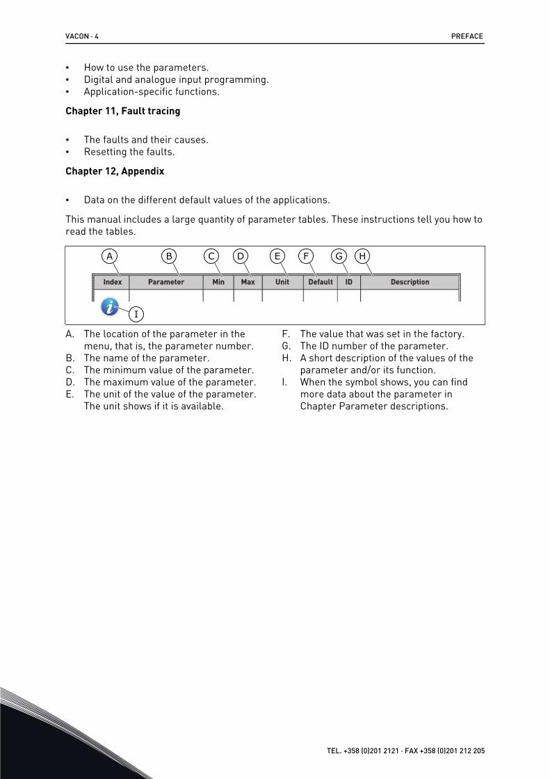
This manual includes a large quantity of parameter tables. These instructions tell you how toread the tables.
Index Min Max Unit Default ID DescriptionParameter
A
I
B C D E F G H
A. The location of the parameter in themenu, that is, the parameter number.
B. The name of the parameter.C. The minimum value of the parameter.D. The maximum value of the parameter.E. The unit of the value of the parameter.
The unit shows if it is available.
F. The value that was set in the factory.G. The ID number of the parameter.H. A short description of the values of the
parameter and/or its function.I. When the symbol shows, you can find
more data about the parameter inChapter Parameter descriptions.
VACON · 4 PREFACE
TEL. +358 (0)201 2121 · FAX +358 (0)201 212 205

NOTE! You can download the English and French product manuals with applicable safety, warning and cautioninformation from www.vacon.com/downloads.
REMARQUE Vous pouvez télécharger les versions anglaise et française des manuels produit contenant l'en-semble des informations de sécurité, avertissements et mises en garde applicables sur le site www.vacon.com/downloads.
Functions of the Vacon® AC drive
• You can select the necessary application for your process: Standard, HVAC, PID control,Multipump (single drive) or Multipump (multidrive). The drive automatically makes someof the necessary settings, which makes the commissioning easy.
• Wizards for the first startup and the Fire mode.• Wizards for each application: Standard, HVAC, PID control, Multipump (single drive) and
Multipump (multidrive).• The FUNCT button for an easy change between the local and the remote control place.
The remote control place can be I/O or fieldbus. You can make a selection of the remotecontrol place with a parameter.
• 8 preset frequencies.• Motor pontentiometer functions.• A flush function.• 2 ramp times that you can program, 2 supervisions and 3 ranges of prohibited
frequencies.• A forced stop.• A control page to operate and monitor of the most important values quickly.• A fieldbus data mapping.• An automatic reset.• Different pre-heat modes to prevent condensation problems.• A maximum output frequency of 320 Hz.• A Real time clock and timer functions (an optional battery is necessary). It is possible to
program 3 time channels to get different functions on the drive.• An external PID controller is available. You can use it, for example, to control a valve with
the I/O of the AC drive.• A sleep mode function that automatically enables and disables the operation of the drive
to save energy.• A 2-zone PID controller with 2 different feedback signals: minimum and maximum
control.• 2 setpoint sources for the PID control. You can make the selection with a digital input.• A function for PID setpoint boost.• A feedforward function to make the response to the process changes better.• A process value supervision.• A multipump control for the single drive and multidrive systems.• The multimaster and multifollower modes in the multidrive system.• A multipump system that uses a real time clock to autochange the pumps.• A maintenance counter.• Pump control functions: priming pump control, jockey pump control, pump impeller
auto-cleaning, pump input pressure supervision and frost protection function.
PREFACE VACON · 5
24-HOUR SUPPORT +358 (0)201 212 575 · EMAIL: [email protected]

VACON · 6
TEL. +358 (0)201 2121 · FAX +358 (0)201 212 205

TABLE OF CONTENTSPreface
About this manual 31 Quick Startup Guide 11
1.1 Control panel and keypad 111.2 The displays 111.3 First startup 121.4 Description of the applications 13
1.4.1 Standard and HVAC applications 131.4.2 PID control application 211.4.3 Multipump (single drive) application 291.4.4 Multipump (multidrive) application 42
2 Wizards 762.1 Standard application wizard 762.2 HVAC application wizard 772.3 PID control application wizard 782.4 Multipump (single drive) application wizard 802.5 Multipump (multidrive) application wizard 832.6 Fire mode wizard 87
3 User interfaces 893.1 Navigation on the keypad 893.2 Using the graphical display 91
3.2.1 Editing the values 913.2.2 Resetting a fault 943.2.3 The FUNCT button 943.2.4 Copying the parameters 983.2.5 Comparing the parameters 1003.2.6 Help texts 1023.2.7 Using the Favourites menu 103
3.3 Using the text display 1033.3.1 Editing the values 1043.3.2 Resetting a fault 1053.3.3 The FUNCT button 105
3.4 Menu structure 1093.4.1 Quick setup 1103.4.2 Monitor 110
3.5 Vacon Live 112
TABLE OF CONTENTS VACON · 7
24-HOUR SUPPORT +358 (0)201 212 575 · EMAIL: [email protected]

4 Monitoring menu 1134.1 Monitor group 113
4.1.1 Multimonitor 1134.1.2 Trend curve 1144.1.3 Basic 1174.1.4 I/O 1204.1.5 Temperature inputs 1204.1.6 Extras and advanced 1224.1.7 Timer functions monitoring 1244.1.8 PID controller monitoring 1264.1.9 External PID controller monitoring 1274.1.10 Multipump monitoring 1274.1.11 Maintenance counters 1294.1.12 Fieldbus process data monitoring 130
5 Parameters menu 1325.1 Group 3.1: Motor settings 1325.2 Group 3.2: Start/stop setup 1385.3 Group 3.3: References 1415.4 Group 3.4: Ramps and brakes setup 1465.5 Group 3.5: I/O configuration 1495.6 Group 3.6: Fieldbus data mapping 1625.7 Group 3.7: Prohibit frequencies 1645.8 Group 3.8: Supervisions 1655.9 Group 3.9: Protections 1665.10 Group 3.10: Automatic reset 1765.11 Group 3.11: Application settings 1785.12 Group 3.12: Timer functions 1795.13 Group 3.13: PID controller 1 1825.14 Group 3.14: External PID controller 2045.15 Group 3.15: Multipump 2095.16 Group 3.16: Maintenance counters 2155.17 Group 3.17: Fire mode 2165.18 Group 3.18: Motor preheat parameters 2185.19 Group 3.21: Pump control 219
6 Diagnostics menu 2256.1 Active faults 2256.2 Reset faults 2256.3 Fault history 2256.4 Total counters 2256.5 Trip counters 2276.6 Software info 228
7 I/O and hardware menu 2297.1 Basic I/O 2297.2 Option board slots 2317.3 Real time clock 2327.4 Power unit settings 232
VACON · 8 TABLE OF CONTENTS
TEL. +358 (0)201 2121 · FAX +358 (0)201 212 205

7.5 Keypad 2337.6 Fieldbus 234
8 User settings, favourites and user level menus 2358.1 User settings 235
8.1.1 User settings 2358.1.2 Parameter backup 236
8.2 Favourites 2368.2.1 Adding an item to the Favourites 2378.2.2 Removing an item from the Favourites 237
8.3 User levels 2388.3.1 Changing the access code of the user levels 239
9 Monitoring value descriptions 24110 Parameter descriptions 243
10.1 Motor settings 24310.1.1 P3.1.4.9 Start Boost (ID 109) 25010.1.2 I/f start function 250
10.2 Start/Stop setup 25110.3 References 259
10.3.1 Frequency reference 25910.3.2 Preset frequencies 25910.3.3 Motor potentiometer parameters 26210.3.4 Flushing parameters 264
10.4 Ramps and brakes setup 26410.5 I/O configuration 266
10.5.1 Programming of digital and analogue inputs 26610.5.2 Default functions of programmable inputs 27710.5.3 Digital inputs 27710.5.4 Analogue inputs 27810.5.5 Digital outputs 28210.5.6 Analogue outputs 284
10.6 Prohibit frequencies 28710.7 Protections 288
10.7.1 Motor thermal protections 28910.7.2 Motor stall protection 29210.7.3 Underload (Dry pump) protection 293
10.8 Automatic reset 29710.9 Timer functions 29810.10 PID controller 302
10.10.1 Feedforward 30310.10.2 Sleep function 30310.10.3 Feedback supervision 30510.10.4 Pressure loss compensation 30610.10.5 Soft fill 30810.10.6 Input pressure supervision 31010.10.7 Sleep function when no demand is detected 31110.10.8 Multi-Setpoint 312
TABLE OF CONTENTS VACON · 9
24-HOUR SUPPORT +358 (0)201 212 575 · EMAIL: [email protected]

10.11 Multipump function 31410.11.1 Multipump (multidrive) commissioning checklist 31410.11.2 System configuration 31610.11.3 Interlocks 32110.11.4 Feedback sensor connection in a multipump system 32110.11.5 Overpressure supervision 33110.11.6 Pump runtime counters 331
10.12 Maintenance counters 33410.13 Fire mode 33410.14 Motor preheat function 33610.15 Pump control 337
10.15.1 Auto-cleaning 33710.15.2 Jockey pump 34010.15.3 Priming pump 34110.15.4 Anti-blocking function 34210.15.5 Frost protection 343
10.16 Counters 34310.16.1 Operating time counter 34310.16.2 Operating time trip counter 34310.16.3 Run time counter 34410.16.4 Power on time counter 34410.16.5 Energy counter 34510.16.6 Energy trip counter 346
11 Fault tracing 34811.1 A fault comes into view 348
11.1.1 Resetting with the Reset button 34811.1.2 Resetting with a parameter in the graphical display 34811.1.3 Resetting with a parameter in the text display 349
11.2 Fault history 35011.2.1 Examining the Fault history in the graphical display 35011.2.2 Examining the Fault history in the text display 351
11.3 Fault codes 35312 Appendix 1 366
12.1 The default values of parameters in the different applications 366
VACON · 10 TABLE OF CONTENTS
TEL. +358 (0)201 2121 · FAX +358 (0)201 212 205

1 QUICK STARTUP GUIDE1.1 CONTROL PANEL AND KEYPAD
The control panel is the interface between the AC drive and the user. With the control panel,you can control the speed of a motor and monitor the status of the AC drive. You can also setthe parameters of the AC drive.
A B C
I
H D
G F E
Fig. 1: The buttons of the keypadA. The BACK/RESET button. Use it to move
back in the menu, exit the Edit mode,reset a fault.
B. The arrow button UP. Use it to scroll themenu up and to increase a value.
C. The FUNCT button. Use it to change therotation direction of the motor, accessthe control page, and change the controlplace. See more in 3.3.3 The FUNCT button.
D. The arrow button RIGHT.E. The START button.F. The arrow button DOWN. Use it to scroll
the menu down and to decrease a value.G. The STOP button.H. The arrow button LEFT. Use it to move
the cursor left.I. The OK button. Use it to go into an active
level or item, or to accept a selection.
1.2 THE DISPLAYS
There are 2 display types: the graphical display and the text display. The control panel alwayshas the same keypad and buttons.
The display shows this data.• The status of the motor and the drive.• Faults in the motor and in the drive.• Your location in the menu structure.
QUICK STARTUP GUIDE VACON · 11
24-HOUR SUPPORT +358 (0)201 212 575 · EMAIL: [email protected] 1

STOP READY I/O
Main Menu
A B C D E
F
H
GQuick Setup( 17 )Monitor( 5 )
Parameters( 12 )
M1ID:
Fig. 2: The graphical displayA. The first status field: STOP/RUNB. The rotation direction of the motorC. The second status field: READY/NOT
READY/FAULTD. The alarm field: ALARM/-E. The control place field: PC/IO/KEYPAD/
FIELDBUS
F. The location field: the ID number of theparameter and the current location inthe menu
G. An activated group or itemH. The number of items in the group in
question
A B
F
C
D
E
Fig. 3: The text display. If the text is too long to show, the text scrolls automatically on the display.A. The indicators of statusB. The indicators of alarm and faultC. The name of the group or item of the
current location
D. The current location in the menuE. The indicators of the control placeF. The indicators of the rotation direction
1.3 FIRST STARTUP
After you do power-up of the drive, the Startup wizard starts.The Startup wizard tells you to give necessary data for the drive to control your procedure.
VACON · 12 QUICK STARTUP GUIDE
1 TEL. +358 (0)201 2121 · FAX +358 (0)201 212 205

1 Language selection (P6.1) The selection is different in all the languagepackages
2
Daylight saving* (P5.5.5)RussiaUSEUOFF
3 Time* (P5.5.2) hh:mm:ss
4 Year* (P5.5.4) yyyy
5 Date* (P5.5.3) dd.mm.
* If a battery is installed, you see these steps
6Run Startup Wizard?
YesNo
Select Yes and push the OK button. If you select No, the AC drive moves away from theStartup wizard.To set the parameter values manually, select No and push the OK button.
7
Select the application (P1.2 Application, ID212)StandardHVACPID controlMultipump (single drive)Multipump (multidrive)
To continue to the wizard of the application you selected in step 7, select Yes and push the OKbutton. See the description of the application wizards in 2 Wizards.
If you select No and push the OK button, the Startup wizard stops and you must select all theparameter values manually.
To start the Startup wizard again, you have 2 alternatives. Go to the parameter P6.5.1Restore Factory Defaults or to the parameter B1.1.2 Startup Wizard. Then set the value toActivate.
1.4 DESCRIPTION OF THE APPLICATIONS
Use the parameter P1.2 (Application) to make a selection of an application for the drive.Immediately when the parameter P1.2 changes, a group of parameters get their presetvalues.
1.4.1 STANDARD AND HVAC APPLICATIONSUse the Standard and HVAC applications to control pumps or fans, for example.
It is possible to control the drive from the Keypad, Fieldbus or I/O terminal.
QUICK STARTUP GUIDE VACON · 13
24-HOUR SUPPORT +358 (0)201 212 575 · EMAIL: [email protected] 1

When you control the drive with the I/O terminal, the frequency reference signal is connectedto AI1 (0…10V) or AI2 (4…20mA). The connection is specified by the type of the signal. Thereare also 3 preset frequency references available. You can activate the preset frequencyreferences with DI4 and DI5. The start and stop signals of the drive are connected to DI1(start forward) and DI2 (start reverse).
It is possible to configure all the drive outputs freely in all the applications. There are 1analogue output (Output Frequency) and 3 relay outputs (Run, Fault, Ready) available on thebasic I/O board.
See the descriptions of the parameters in 10 Parameter descriptions.
VACON · 14 QUICK STARTUP GUIDE
1 TEL. +358 (0)201 2121 · FAX +358 (0)201 212 205

RUN
FAULT
READY
Reference output+10 Vref
TerminalStandard I/O board
Signal
1
24V auxiliary voltage24Vout6
Analogue input 1 +AI1+2
AI1-3
Analogue input 2 + AI2+4
AI2-5
Analogue output 1 +AO1+
RUN
18Analogue output 1 -AO1-19
+24Vin30
24V auxiliary voltage24Vout12
I/O groundGND7
I/O groundGND13
Digital input 1DI18
Digital input 2DI29
Digital input 3DI310
Digital input 4DI414
Digital input 5DI515
Digital input 6DI616
Relay output 1RO1/1 NC21
22 RO1/2 CM
RO1/3 NO23
Common for DI1-DI6CM11
Common for DI1-DI6CM17
Serial bus, negativeRS485A
Serial bus, positiveRS485B
Relay output 2
Relay output 3
RO2/1 NC24
25 RO2/2 CM
RO2/3 NO26
32 RO3/2 CM
RO3/3 NO33
Description
Frequency reference(default 0...10V)
Frequency reference(Default 4...20mA)
Start forward
Start reverse
External fault
DI4 DI5 Freq. ref.OpenClosedOpenClosed
OpenOpenClosedClosed
Analog input 1Preset Freq. 1Preset Freq. 2Preset Freq. 3
Fault reset
Output frequency(default: 0...20mA)
Modbus RTU N2, BACnet
Analogue input 1 -
FAULT
Analogue input 2 -
Referencepotentiom-
eter
1...10kΩ
mA
*)
*)
**)
24V auxiliary input voltage
Fig. 4: The default control connections of Standard and HVAC applications
* = You can isolate the digital inputs from the ground with a DIP switch.
QUICK STARTUP GUIDE VACON · 15
24-HOUR SUPPORT +358 (0)201 212 575 · EMAIL: [email protected] 1

** = If you use the +SBF4 option code, a thermistor input replaces the relay output 3. SeeInstallation Manual.
AB
C
Fig. 5: The DIP switchA. Digital inputsB. Float
C. Connected to GND (default)
Table 2: M1.1 Wizards
Index Parameter Min Max Unit Default ID Description
1.1.1 Startup Wizard 0 1 0 1170
0 = Do not activate1 = Activate
The selection Activatestarts the Startup wiz-ard (see Table 1 The Startup wizard).
1.1.2 Fire Mode Wizard 0 1 0 1672
The selection Activatestarts the Fire modewizard (see 2.6 Fire mode wizard).
VACON · 16 QUICK STARTUP GUIDE
1 TEL. +358 (0)201 2121 · FAX +358 (0)201 212 205

Table 3: M1 Quick Setup
Index Parameter Min Max Unit Default ID Description
1.2
Application 0 4 0 212
0 = Standard1 = HVAC2 = PID Control3 = Multipump (singledrive)4 = Multipump (multi-drive)
1.3 Minimum FrequencyReference 0.00 P1.4 Hz 0.0 101
The minimum fre-quency reference thatis accepted.
1.4 Maximum FrequencyReference P1.3 320.0 Hz 50.0 /
60.0 102The maximum fre-quency reference thatis accepted.
1.5 Acceleration Time 1 0.1 3000.0 s 5.0 103
Gives the quantity oftime that is necessaryfor the output fre-quency to increasefrom 0 frequency to themaximum frequency.
1.6 Deceleration Time 1 0.1 3000.0 s 5.0 104
Gives the quantity oftime that is necessaryfor the output fre-quency to decreasefrom the maximumfrequency to 0 fre-quency.
1.7 Motor Current Limit IH*0.1 IS A Varies 107The maximum motorcurrent from the ACdrive.
1.8 Motor Type 0 1 0 650 0 = Induction Motor1 = Permanent MagnetMotor
1.9 Motor Nominal Volt-age Varies Varies V Varies 110
Find this value Un onthe rating plate of themotor.
NOTE!Find out if the motorconnection is Delta orStar.
QUICK STARTUP GUIDE VACON · 17
24-HOUR SUPPORT +358 (0)201 212 575 · EMAIL: [email protected] 1

Table 3: M1 Quick Setup
Index Parameter Min Max Unit Default ID Description
1.10 Motor Nominal Fre-quency 8.0 320.0 Hz 50 / 60 111
Find this value fn onthe rating plate of themotor.
1.11 Motor NominalSpeed 24 19200 Rpm Varies 112
Find this value nn onthe rating plate of themotor.
1.12 Motor Nominal Cur-rent IH * 0.1 IH * 2 A Varies 113
Find this value In onthe rating plate of themotor.
1.13 Motor Cos Phi(Power Factor) 0.30 1.00 Varies 120
Find this value on therating plate of themotor.
1.14 Energy Optimisation 0 1 0 666
The drive finds theminimum motor cur-rent to use less energyand to lower the motornoise. Use this functionwith, for example, fanand pump processes.
0 = Disabled1 = Enabled
1.15 Identification 0 2 0 631
The identification runcalculates or measuresthe motor parametersthat are necessary fora good control of themotor and speed.
0 = No action1 = At standstill2 = With rotation
Before you do the iden-tification run, you mustset the motor name-plate parameters.
1.16 Start Function 0 1 0 505 0 = Ramping1 = Flying Start
1.17 Stop Function 0 1 0 506 0 = Coasting1 = Ramping
VACON · 18 QUICK STARTUP GUIDE
1 TEL. +358 (0)201 2121 · FAX +358 (0)201 212 205

Table 3: M1 Quick Setup
Index Parameter Min Max Unit Default ID Description
1.18 Automatic Reset 0 1 0 731 0 = Disabled1 = Enabled
1.19 Response to ExternalFault 0 3 2 701
0 = No action1 = Alarm2 = Fault (Stop accord-ing to stop mode)3 = Fault (Stop bycoasting)
1.20 Response to AI LowFault 0 5 0 700
0 = No action1 = Alarm2 = Alarm+preset faultfrequency (P3.9.1.13)3 = Alarm + previousfrequency4 = Fault (Stop accord-ing to stop mode)5 = Fault (Stop bycoasting)
1.21 Remote ControlPlace 0 1 0 172
The selection of theremote control place(start/stop).
0 = I/O control1 = Fieldbus control
QUICK STARTUP GUIDE VACON · 19
24-HOUR SUPPORT +358 (0)201 212 575 · EMAIL: [email protected] 1

Table 3: M1 Quick Setup
Index Parameter Min Max Unit Default ID Description
1.22 I/O Control Refer-ence A Selection 0 20 5 117
The selection of thefrequency referencesource when the con-trol place is I/O A.
0 = PC1 = Preset Frequency 02 = Keypad Reference3 = Fieldbus4 = AI15 = AI25 = AI1+AI27 = PID Reference8 = Motor Potentiome-ter11 = Block Out.112 = Block Out.213 = Block Out.314 = Block Out.415 = Block Out.516 = Block Out.617 = Block Out.718 = Block Out.819 = Block Out.920 = Block Out.10
The application thatyou set with parameter1.2 gives the defaultvalue.
1.23 Keypad Control Ref-erence Selection 0 20 1 121
The selection of thefrequency referencesource when the con-trol place is keypad.See P1.22.
1.24 Fieldbus ControlReference Selection 0 20 2 122
The selection of thefrequency referencesource when the con-trol place is fieldbus.See P1.22.
1.25 AI1 Signal Range 0 1 0 379 0= 0..10V / 0..20mA1= 2..10V / 4..20mA
1.26 AI2 Signal Range 0 1 1 390 0= 0..10V / 0..20mA1= 2..10V / 4..20mA
1.27 RO1 Function 0 51 2 1101 See P3.5.3.2.1
1.28 RO2 Function 0 51 3 1104 See P3.5.3.2.1
VACON · 20 QUICK STARTUP GUIDE
1 TEL. +358 (0)201 2121 · FAX +358 (0)201 212 205

Table 3: M1 Quick Setup
Index Parameter Min Max Unit Default ID Description
1.29 RO3 Function 0 51 1 1107 See P3.5.3.2.1
1.30 AO1 Function 0 31 2 10050 See P3.5.4.1.1
Table 4: M1.31 Standard / M1.32 HVAC
Index Parameter Min Max Unit Default ID Description
1.31.1 Preset Frequency 1 P1.3 P1.4 Hz 10.0 105Make the selection of apreset frequency withthe digital input DI4.
1.31.2 Preset Frequency 2 P1.3 P1.4 Hz 15.0 106Make the selection of apreset frequency withthe digital input DI5.
1.31.3 Preset Frequency 3 P1.3 P1.4 Hz 20.0 126
Make the selection of apreset frequency withthe digital input DI4and DI5.
1.4.2 PID CONTROL APPLICATIONYou can use the PID control application with processes where you control the processvariable, for example pressure, through the control of the speed of the motor.
In this application, the internal PID controller of the drive is configured for 1 setpoint and 1feedback signal.
You can use 2 control places. Make the selection of the control place A or B with DI6. Whencontrol place A is active, DI1 gives the start and stop commands, and the PID controller givesthe frequency reference. When control place B is active, DI4 gives the start and stopcommands, and AI1 gives the frequency reference.
You can configure all the drive outputs freely in all the applications. There are 1 analogueoutput (Output Frequency) and 3 relay outputs (Run, Fault, Ready) available on the basic I/Oboard.
See the descriptions of the parameters in Table 1 The Startup wizard.
QUICK STARTUP GUIDE VACON · 21
24-HOUR SUPPORT +358 (0)201 212 575 · EMAIL: [email protected] 1

*)
*)
+
-
**)
1
6
2
3
4
5
18
19
30
12
7
13
8
9
10
14
15
16
212223
11
17
A
B
2425
26
32
33
Modbus RTU
mA
FAULT
RUNRUN
AO1-/GND
+24 Vin
24V out
GND
GND
DI1
DI2
DI3
DI4
DI5
DI6
RO1/1 NC
RO1/2 CMRO1/3 NO
CM
CM
RS485
RS485
RO2/1 NC
RO2/2 CM
RO2/3 NO
RO3/2 CM
RO3/3 NO
Standard I/O board
Terminal Signal Description+10Vref
AI1+
AI1-
AI2+
AI2-
24Vout
Reference output
Analogue input 1 +
Analogue input 1 -
Analogue input 2 +
Analogue input 2 -
24V auxiliary voltage
I/O ground
Digital input 1
Digital input 2
Digital input 3
Digital input 4
Digital input 5
Digital input 6
Common for DI1-DI6
Common for DI1-DI6
24V auxiliary voltage
I/O ground
Analogue output 1 +
Analogue output 1 -
24V auxiliaryinput voltage
Output frequency 0...20mA)
READY
Serial bus, negativeSerial bus, positive
Relay output 1
Relay output 2
Relay output 3
FAULT
Fault reset
AO1+
Place A: PID setpoint (reference) Place B: Frequency reference (default: 0...10V)
PID feedback (actual value) (default: 4...20mA)
Place A: Start forward (PID controller)
External fault
Control place A/B selection
Reference-potentiom-
eter 1...10kΩ
Preset frequency 1
I = (0)4...20mA
Actual value
2-wire transmitter
Place B: Start forward (Freq. reference P3.3.1.6)
Fig. 6: The default control connections of the PID control application
* = You can isolate the digital inputs from the ground with a DIP switch.
VACON · 22 QUICK STARTUP GUIDE
1 TEL. +358 (0)201 2121 · FAX +358 (0)201 212 205

** = If you use the +SBF4 option code, a thermistor input replaces the relay output 3. SeeInstallation Manual.
AB
C
Fig. 7: The DIP switchA. Digital inputsB. Float
C. Connected to GND (default)
Table 5: M1.1 Wizards
Index Parameter Min Max Unit Default ID Description
1.1.1 Startup Wizard 0 1 0 1170
0 = Do not activate1 = Activate
The selection Activatestarts the Startup wiz-ard (see 1.3 First startup).
1.1.2 Fire Mode Wizard 0 1 0 1672
The selection Activatestarts the Fire modewizard (see 2.6 Fire mode wizard).
QUICK STARTUP GUIDE VACON · 23
24-HOUR SUPPORT +358 (0)201 212 575 · EMAIL: [email protected] 1

Table 6: M1 Quick Setup
Index Parameter Min Max Unit Default ID Description
1.2
Application 0 4 2 212
0 = Standard1 = HVAC2 = PID Control3 = Multipump (singledrive)4 = Multipump (multi-drive)
1.3 Minimum FrequencyReference 0.00 P1.4 Hz 0.0 101
The minimum fre-quency reference thatis accepted.
1.4 Maximum FrequencyReference P1.3 320.0 Hz 50.0 /
60.0 102The maximum fre-quency reference thatis accepted.
1.5 Acceleration Time 1 0.1 3000.0 s 5.0 103
Gives the quantity oftime that is necessaryfor the output fre-quency to increasefrom 0 frequency to themaximum frequency.
1.6 Deceleration Time 1 0.1 3000.0 s 5.0 104
Gives the quantity oftime that is necessaryfor the output fre-quency to decreasefrom the maximumfrequency to 0 fre-quency.
1.7 Motor Current Limit IH*0.1 IS A Varies 107The maximum motorcurrent from the ACdrive.
1.8 Motor Type 0 1 0 650 0 = Induction Motor1 = Permanent MagnetMotor
1.9 Motor Nominal Volt-age Varies Varies V Varies 110
Find this value Un onthe rating plate of themotor.
NOTE!Find out if the motorconnection is Delta orStar.
VACON · 24 QUICK STARTUP GUIDE
1 TEL. +358 (0)201 2121 · FAX +358 (0)201 212 205

Table 6: M1 Quick Setup
Index Parameter Min Max Unit Default ID Description
1.10 Motor Nominal Fre-quency 8.0 320.0 Hz 50.0 /
60.0 111Find this value fn onthe rating plate of themotor.
1.11 Motor NominalSpeed 24 19200 Rpm Varies 112
Find this value nn onthe rating plate of themotor.
1.12 Motor Nominal Cur-rent IH * 0.1 IS A Varies 113
Find this value In onthe rating plate of themotor.
1.13 Motor Cos Phi(Power Factor) 0.30 1.00 Varies 120
Find this value on therating plate of themotor.
1.14 Energy Optimisation 0 1 0 666
The drive finds theminimum motor cur-rent to use less energyand to lower the motornoise. Use this functionwith, for example, fanand pump processes.
0 = Disabled1 = Enabled
1.15 Identification 0 2 0 631
The identification runcalculates or measuresthe motor parametersthat are necessary fora good control of themotor and speed.
0 = No action1 = At standstill2 = With rotation
Before you do the iden-tification run, you mustset the motor name-plate parameters.
1.16 Start Function 0 1 0 505 0 = Ramping1 = Flying Start
1.17 Stop Function 0 1 0 506 0 = Coasting1 = Ramping
QUICK STARTUP GUIDE VACON · 25
24-HOUR SUPPORT +358 (0)201 212 575 · EMAIL: [email protected] 1

Table 6: M1 Quick Setup
Index Parameter Min Max Unit Default ID Description
1.18 Automatic Reset 0 1 0 731 0 = Disabled1 = Enabled
1.19 Response to ExternalFault 0 3 2 701
0 = No action1 = Alarm2 = Fault (Stop accord-ing to stop mode)3 = Fault (Stop bycoasting)
1.20 Response to AI LowFault 0 5 0 700
0 = No action1 = Alarm2 = Alarm+preset faultfrequency (P3.9.1.13)3 = Alarm + previousfrequency4 = Fault (stop accord-ing to stop mode)5 = Fault (stop bycoasting)
1.21 Remote ControlPlace 0 1 0 172
The selection of theremote control place(start/stop).
0 = I/O control1 = Fieldbus control
VACON · 26 QUICK STARTUP GUIDE
1 TEL. +358 (0)201 2121 · FAX +358 (0)201 212 205

Table 6: M1 Quick Setup
Index Parameter Min Max Unit Default ID Description
1.22 I/O Control Refer-ence A Selection 1 20 6 117
The selection of thefrequency referencesource when the con-trol place is I/O A.
0 = PC1 = Preset Frequency 02= Keypad Reference3 = Fieldbus4 = AI15 = AI26 = AI1+AI27 = PID Reference8 = Motor Potentiome-ter11 = Block Out.112 = Block Out.213 = Block Out.314 = Block Out.415 = Block Out.516 = Block Out.617 = Block Out.718 = Block Out.819 = Block Out.920 = Block Out.10
The application thatyou set with parameter1.2 gives the defaultvalue.
1.23 Keypad Control Ref-erence Selection 1 20 1 121 See P1.22.
1.24 Fieldbus ControlReference Selection 1 20 2 122 See P1.22.
1.25 AI1 Signal Range 0 1 0 379 0= 0..10V / 0..20mA1= 2..10V / 4..20mA
1.26 AI2 Signal Range 0 1 1 390 0= 0..10V / 0..20mA1= 2..10V / 4..20mA
1.27 RO1 Function 0 51 2 11001 See P3.5.3.2.1
1.28 RO2 Function 0 51 3 11004 See P3.5.3.2.1
1.29 RO3 Function 0 51 1 11007 See P3.5.3.2.1
1.30 AO1 Function 0 31 2 10050 See P3.5.4.1.1
QUICK STARTUP GUIDE VACON · 27
24-HOUR SUPPORT +358 (0)201 212 575 · EMAIL: [email protected] 1

Table 7: M1.33 PID control
Index Parameter Min Max Unit Default ID Description
1.33.1 PID Gain 0.00 100.00 % 100.00 118
If the value of theparameter is set to100%, a change of 10%in the error value cau-ses the controller out-put to change by 10%.
1.33.2 PID Integration Time 0.00 600.00 s 1.00 119
If this parameter is setto, 1,00 s, a change of10% in the error valuecauses the controlleroutput to change by10.00%/s.
1.33.3 PID Derivation Time 0.00 100.00 s 0.00 1132
If this parameter is setto 1,00 s, a change of10% in the error valueduring 1.00 s causesthe controller output tochange by 10.00%.
1.33.4 Process Unit Selec-tion 1 44 1 1036 Select the unit of the
process. See P3.13.1.4
1.33.5 Process Unit Min Varies Varies Varies 1033
The process unit valuethat is the same as 0%of the PID feedbacksignal.
1.33.6 Process Unit Max Varies Varies Varies 1034
The process unit valuethat is the same as100% of the PID feed-back signal.
1.33.7 Feedback 1 SourceSelection 0 30 2 334 See P3.13.3.3
1.33.8 Setpoint 1 SourceSelection 0 32 1 332 See P3.13.2.6
1.33.9 Keypad Setpoint 1 Varies Varies Varies 0 167
1.33.10 Sleep FrequencyLimit 1 0.0 320.0 Hz 0.0 1016
The drive goes to thesleep mode when theoutput frequency staysbelow this limit for lon-ger than is specified byparameter Sleep Delay.
1.33.11 Sleep Delay 1 0 3000 s 0 1017
The minimum quantityof time that the fre-quency stays below thesleep level before thedrive stops.
VACON · 28 QUICK STARTUP GUIDE
1 TEL. +358 (0)201 2121 · FAX +358 (0)201 212 205

Table 7: M1.33 PID control
Index Parameter Min Max Unit Default ID Description
1.33.12 Wake-up Level 1 Varies Varies Varies Varies 1018
The wake-up value ofthe PID feedbacksupervision. Wake-upLevel 1 uses the selec-ted process units.
1.33.12 Preset Frequency 1 P1.3 P1.4 Hz 10.0 105The preset frequencythat the the digitalinput DI5 selects.
1.4.3 MULTIPUMP (SINGLE DRIVE) APPLICATIONYou can use Multipump (single drive) application in applications, where 1 drive controls asystem that has the maximum of 8 parallel motors, for example, pumps, fans orcompressors. By default, Multipump (single drive) application is configured for 3 parallelmotors.The drive is connected to 1 of the motors, which becomes the regulating motor. The internalPID controller of the drive controls the speed of the regulating motor and gives controlsignals by relay outputs to start or stop the auxiliary motors. External contactors (switch) setthe auxiliary motors to the mains.
You can control a process variable, the pressure for example, by the control of the speed ofthe regulating motor and by the number of motors that operate.
See the descriptions of the parameters in 10 Parameter descriptions.
QUICK STARTUP GUIDE VACON · 29
24-HOUR SUPPORT +358 (0)201 212 575 · EMAIL: [email protected] 1

PT
Start / Stop
Fig. 8: Multipump (single drive) configuration
Autochange function (change of start order) makes the wear of the motors in the systemmore equal. Autochange function monitors the running hours and sets the start order ofeach motor. The motor that has the lowest running hours starts first and the motor that hasthe highest running hours starts last. You can configure the autochange to start based on theautochange interval time set by the internal real time clock (an RTC battery needed) of thedrive.
You can configure the autochange for all the motors in the system or only the auxiliarymotors.
VACON · 30 QUICK STARTUP GUIDE
1 TEL. +358 (0)201 2121 · FAX +358 (0)201 212 205

K2 K3
Fig. 9: Control diagram, where only the auxiliary motors are configured to autochange
K1 K2 K2 K1.1 K2.1 K3.1
Fig. 10: Control diagram, where all the motors are configured to autochange
You can use 2 control places. Make the selection of the control place A or B with DI6. Whencontrol place Make the selection of the control place A or B with DI6. When control place A isactive, DI1 gives the start and stop commands, and the PID controller gives the frequencyreference. When control place B is active, DI4 gives the start and stop commands, and AI1gives the frequency reference.
QUICK STARTUP GUIDE VACON · 31
24-HOUR SUPPORT +358 (0)201 212 575 · EMAIL: [email protected] 1

You can configure all the drive outputs freely in all the applications. There are 1 analogueoutput (Output Frequency) and 3 relay outputs (Run, Fault, Ready) available on the basic I/Oboard.
VACON · 32 QUICK STARTUP GUIDE
1 TEL. +358 (0)201 2121 · FAX +358 (0)201 212 205

*)
*)
+
-
**)
A1
A1
A1
A2
A2
A2
1
6
2
3
4
5
18
19
30
12
7
13
8
9
10
14
15
16
212223
11
17
A
B
2425
26
32
33
Modbus RTU
mA
Motor 1 control(Multi-pump K2 contactor)
Motor 2 control(Multi-pump K2 contactor)
Motor 3 control(Multi-pump K2 contactor)
AO1-/GND
+24Vin
GND
GND
DI1
DI2
DI3
DI4
DI5
DI6
RO1/1 NC
RO1/2 CMRO1/3 NO
CM
CM
RS485
RS485
RO2/1 NC
RO2/2 CM
RO2/3 NO
RO3/2 CM
RO3/3 NO
Standard I/O board
Terminal Signal Description+10Vref
AI1+
AI1-
AI2+
AI2-
24Vout
Reference output
Analogue input 1 +
Analogue input 1 -
Analogue input 2 +
Analogue input 2 -
24V auxiliary voltage
I/O ground
Digital input 1
Digital input 2
Digital input 3
Digital input 4
Digital input 5
Digital input 6
Common for DI1-DI6
Common for DI1-DI6
24V auxiliary voltage
I/O ground
Analogue output 1 +
Analogue output 1 -
24V auxiliaryinput voltage
Output frequency
( default 0...20mA)
Serial bus, negativeSerial bus, positive
Relay output 1
Relay output 2
Relay output 3
Control place A/B selection
AO1+
Place A: Not used Place B: Frequency reference (default: 0...10V)
PID feedback (actual value) (default: 4...20mA)
Place A: Start forward (PID controller)Place B: Start forward (Freq. ref. P3.3.1.6 )
Reference-potentiom-
eter 1...10kΩ
I = (0)4...20mA
Actual value
2-wire transmitter
Motor 1 interlock
Motor 2 interlock
Motor 3 interlock
24Vout
Fig. 11: The default control connections of Multipump (single drive) application
* = You can isolate the digital inputs from the ground with a DIP switch.
QUICK STARTUP GUIDE VACON · 33
24-HOUR SUPPORT +358 (0)201 212 575 · EMAIL: [email protected] 1

** = If you use the +SBF4 option code, a thermistor input replaces the relay output 3. SeeInstallation Manual.
AB
C
Fig. 12: The DIP switchA. Digital inputsB. Float
C. Connected to GND (default)
Table 8: M1.1 Wizards
Index Parameter Min Max Unit Default ID Description
1.1.1 Startup Wizard 0 1 0 1170
0 = Do not activate1 = Activate
The selection Activatestarts the Startup wiz-ard (see 1.3 First startup).
1.1.2 Fire Mode Wizard 0 1 0 1672
The selection Activatestarts the Fire modewizard (see 2.6 Fire mode wizard).
VACON · 34 QUICK STARTUP GUIDE
1 TEL. +358 (0)201 2121 · FAX +358 (0)201 212 205

Table 9: M1 Quick Setup
Index Parameter Min Max Unit Default ID Description
1.2
Application 0 4 2 212
0 = Standard1 = HVAC2 = PID Control3 = Multipump (singledrive)4 = Multipump (multi-drive)
1.3 Minimum FrequencyReference 0.00 P1.4 Hz 0.0 101
The minimum fre-quency reference thatis accepted.
1.4 Maximum FrequencyReference P1.3 320.0 Hz 50.0 /
60.0 102The maximum fre-quency reference thatis accepted.
1.5 Acceleration Time 1 0.1 3000.0 s 5.0 103
Gives the quantity oftime that is necessaryfor the output fre-quency to increasefrom 0 frequency to themaximum frequency.
1.6 Deceleration Time 1 0.1 3000.0 s 5.0 104
Gives the quantity oftime that is necessaryfor the output fre-quency to decreasefrom the maximumfrequency to 0 fre-quency.
1.7 Motor Current Limit IH*0.1 IS A Varies 107The maximum motorcurrent from the ACdrive.
1.8 Motor Type 0 1 0 650 0 = Induction Motor1 = Permanent MagnetMotor
1.9 Motor Nominal Volt-age Varies Varies V Varies 110
Find this value Un onthe rating plate of themotor.
NOTE!Find out if the motorconnection is Delta orStar.
QUICK STARTUP GUIDE VACON · 35
24-HOUR SUPPORT +358 (0)201 212 575 · EMAIL: [email protected] 1

Table 9: M1 Quick Setup
Index Parameter Min Max Unit Default ID Description
1.10 Motor Nominal Fre-quency 8.0 320.0 Hz 50.0 /
60.0 111Find this value fn onthe rating plate of themotor.
1.11 Motor NominalSpeed 24 19200 Rpm Varies 112
Find this value nn onthe rating plate of themotor.
1.12 Motor Nominal Cur-rent IH * 0.1 IS A Varies 113
Find this value In onthe rating plate of themotor.
1.13 Motor Cos Phi(Power Factor) 0.30 1.00 Varies 120
Find this value on therating plate of themotor.
1.14 Energy Optimisation 0 1 0 666
The drive finds theminimum motor cur-rent to use less energyand to lower the motornoise. Use this functionwith, for example, fanand pump processes.
0 = Disabled1 = Enabled
1.15 Identification 0 2 0 631
The identification runcalculates or measuresthe motor parametersthat are necessary fora good control of themotor and speed.
0 = No action1 = At standstill2 = With rotation
Before you do the iden-tification run, you mustset the motor name-plate parameters.
1.16 Start Function 0 1 0 505 0 = Ramping1 = Flying Start
1.17 Stop Function 0 1 0 506 0 = Coasting1 = Ramping
VACON · 36 QUICK STARTUP GUIDE
1 TEL. +358 (0)201 2121 · FAX +358 (0)201 212 205

Table 9: M1 Quick Setup
Index Parameter Min Max Unit Default ID Description
1.18 Automatic Reset 0 1 0 731 0 = Disabled1 = Enabled
1.19 Response to ExternalFault 0 3 2 701
0 = No action1 = Alarm2 = Fault (Stop accord-ing to stop mode)3 = Fault (Stop bycoasting)
1.20 Response to AI LowFault 0 5 0 700
0 = No action1 = Alarm2 = Alarm+preset faultfrequency (P3.9.1.13)3 = Alarm + previousfrequency4 = Fault (stop accord-ing to stop mode)5 = Fault (stop bycoasting)
1.21 Remote ControlPlace 0 1 0 172
The selection of theremote control place(start/stop).
0 = I/O control1 = Fieldbus control
QUICK STARTUP GUIDE VACON · 37
24-HOUR SUPPORT +358 (0)201 212 575 · EMAIL: [email protected] 1

Table 9: M1 Quick Setup
Index Parameter Min Max Unit Default ID Description
1.22 I/O Control Refer-ence A Selection 1 20 6 117
The selection of thefrequency referencesource when the con-trol place is I/O A.
0 = PC1 = Preset Frequency 02= Keypad Reference3 = Fieldbus4 = AI15 = AI26 = AI1+AI27 = PID Reference8 = Motor Potentiome-ter11 = Block Out.112 = Block Out.213 = Block Out.314 = Block Out.415 = Block Out.516 = Block Out.617 = Block Out.718 = Block Out.819 = Block Out.920 = Block Out.10
The application thatyou set with parameter1.2 gives the defaultvalue.
1.23 Keypad Control Ref-erence Selection 1 20 1 121 See P1.22.
1.24 Fieldbus ControlReference Selection 1 20 2 122 See P1.22.
1.25 AI1 Signal Range 0 1 0 379 0= 0..10V / 0..20mA1= 2..10V / 4..20mA
1.26 AI2 Signal Range 0 1 1 390 0= 0..10V / 0..20mA1= 2..10V / 4..20mA
1.27 RO1 Function 0 51 2 11001 See P3.5.3.2.1
1.28 RO2 Function 0 51 3 11004 See P3.5.3.2.1
1.29 RO3 Function 0 51 1 11007 See P3.5.3.2.1
1.30 AO1 Function 0 31 2 10050 See P3.5.4.1.1
VACON · 38 QUICK STARTUP GUIDE
1 TEL. +358 (0)201 2121 · FAX +358 (0)201 212 205

Table 10: M1.34 Multipump (single drive)
Index Parameter Min Max Unit Default ID Description
1.34.1 PID Gain 0.00 100.00 % 100.00 118
If the value of theparameter is set to100%, a change of10% in the errorvalue causes thecontroller output tochange by 10%.
1.34.2 PID IntegrationTime 0.00 600.00 s 1.00 119
If this parameter isset to, 1,00 s, achange of 10% inthe error valuecauses the control-ler output tochange by10.00%/s.
1.34.3 PID DerivationTime 0.00 100.00 s 0.00 1132
If this parameter isset to 1,00 s, achange of 10% inthe error valueduring 1.00 s cau-ses the controlleroutput to change by10.00%.
1.34.4 Process UnitSelection 1 44 1 1036
Select the unit ofthe process. SeeP3.13.1.4
1.34.5 Process Unit Min Varies Varies Varies 1033
The process unitvalue that is thesame as 0% of thePID feedback sig-nal.
1.34.6 Process UnitMax Varies Varies Varies 1034
The process unitvalue that is thesame as 100% ofthe PID feedbacksignal.
1.34.7 Feedback 1Source Selection 0 30 2 334 See P3.13.3.3
1.34.8 Setpoint 1Source Selection 0 32 1 332 See P3.13.2.6
1.34.9 Keypad Setpoint1 Varies Varies Varies 0 167
QUICK STARTUP GUIDE VACON · 39
24-HOUR SUPPORT +358 (0)201 212 575 · EMAIL: [email protected] 1

Table 10: M1.34 Multipump (single drive)
Index Parameter Min Max Unit Default ID Description
1.34.10 Sleep FrequencyLimit 1 0.0 320.0 Hz 0.0 1016
The drive goes tothe sleep modewhen the outputfrequency staysbelow this limit forlonger than isspecified byparameter SleepDelay.
1.34.11 Sleep Delay 1 0 3000 s 0 1017
The minimumquantity of timethat the frequencystays below thesleep level beforethe drive stops.
1.34.12 Wake-up Level 1 Varies Varies Varies Varies 1018
The wake-up valueof the PID feedbacksupervision. Wake-up Level 1 uses theselected processunits.
1.34.13 Multipump Mode 0 2 0 1785
Selects the multi-pump mode.
0= Single drive1= Multifollower2= Multimaster
1.34.14 Number ofPumps 1 8 1 1001
Total number ofmotors (pumps/fans) used in themultipump system.
1.34.15 Pump Interlock-ing 0 1 1 1032
Enable/Disableinterlocks. Inter-locks tell the sys-tem if a motor isconnected or not.
0 = Disabled1 = Enabled
VACON · 40 QUICK STARTUP GUIDE
1 TEL. +358 (0)201 2121 · FAX +358 (0)201 212 205

Table 10: M1.34 Multipump (single drive)
Index Parameter Min Max Unit Default ID Description
1.34.16 Autochange 0 2 1 1027
Disable/enable therotation of the startorder and the pri-ority of the motors.
0 = Disabled1 = Enabled (inter-val)2 = Enabled (week-days)
1.34.17 AutochangedPump 0 1 1 1028 0 = Auxiliary Pump
1 = All Pumps
1.34.18 AutochangeInterval 0.0 3000.0 h 48.0 1029
When the timespecified by thethis parameter isused, the autoch-ange functionstarts. But theautochange startsonly if the capacityis below the levelspecified byparametersP3.15.11 andP3.15.12.
1.34.19 Autochange Days 0 127 15904
Range
B0 = SundayB1 = MondayB2 = TuesdayB3 = WednesdayB4 = ThursdayB5 = FridayB6 = Saturday
1.34.20 Autochange Timeof Day 00:00:00 23:59:59 Time 15905 Range:
00:00:00-23:59:59
1.34.21 Autochange:Frequency Limit 0.00 P3.3.1.2 Hz 25:00 1031 These parameters
set the level belowwhich the capacitymust stay for theautochange tostart.
1.34.22 Autochange:Pump Limit 1 6 1030
QUICK STARTUP GUIDE VACON · 41
24-HOUR SUPPORT +358 (0)201 212 575 · EMAIL: [email protected] 1

Table 10: M1.34 Multipump (single drive)
Index Parameter Min Max Unit Default ID Description
1.34.23 Bandwidth 0 100 % 10 1097
The percent of thesetpoint. For exam-ple,
Setpoint = 5 barBandwidth = 10%
When the feedbackvalue staysbetween 4.5 and5.5 bar, the motorstays connected.
1.34.24 Bandwidth Delay 0 3600 s 10 1098
When the feedbackis outside thebandwidth, thetime after whichpumps are addedor removed.
1.34.25 Pump 1 Interlock DigINSlot0.1 426 OPEN = Not active
CLOSED = Active
1.34.26 Pump 2 Interlock DigINSlot0.1 427 See 1.34.25
1.34.27 Pump 3 Interlock DigINSlot0.1 428 See 1.34.25
1.34.28 Pump 4 Interlock DigINSlot0.1 429 See 1.34.25
1.34.29 Pump 5 Interlock DigINSlot0.1 430 See 1.34.25
1.34.30 Pump 6 Interlock DigINSlot0.1 486 See 1.34.25
1.34.31 Pump 7 Interlock DigINSlot0.1 487 See 1.34.25
1.34.32 Pump 8 Interlock DigINSlot0.1 488 See 1.34.25
1.4.4 MULTIPUMP (MULTIDRIVE) APPLICATIONYou can use the Multipump (multidrive) application in a system that has the maximum of 8parallel speed motors with different speeds, for example, pumps, fans or compressors. Bydefault, the Multipump (Multidrive) application is configured for 3 parallel motors.
See the descriptions of the parameters in 10 Parameter descriptions.
VACON · 42 QUICK STARTUP GUIDE
1 TEL. +358 (0)201 2121 · FAX +358 (0)201 212 205

The checklist for the commissioning a multipump (multidrive) system is in 10.11.1 Multipump (multidrive) commissioning checklist.
Each motor has a drive controls that applicable motor. The drives of the systemcommunicate with each other by Modbus RTU communication.
PT
FB
Start / Stop
Fig. 13: Multipump (multidrive) configuration
You can control a process variable, the pressure for example, by the control of the speed ofthe regulating motor and by the number of motors that operate. The internal PID controllerin the drive of the regulating motor controls the speed, the start and stop of the motors.
The operation of the system is specified by the selected operation mode. In the Multifollowermode, auxiliary motors follow the speed of the regulating motor.
Pump 1 controls and pumps 2 and 3 follow the speed of pump 1, as the curves A show.
QUICK STARTUP GUIDE VACON · 43
24-HOUR SUPPORT +358 (0)201 212 575 · EMAIL: [email protected] 1

A
P1 P2 P3
fmax
fmin
RPM
t
Fig. 14: Control in the Multifollower mode
The figure below shows an example of the Multimaster mode, where the speed of theregulating motor locks to the constant production speed B, when next motor starts. Curves Ashow the regulating of the pumps.
P1 P2 P3
A
B
fmax
fmin
RPM
t
Fig. 15: Control in the Multimaster mode
Autochange function (change of start order) makes the wear of the motors in the systemmore equal. Autochange function monitors the running hours and sets the start order ofeach motor. The motor that has the lowest running hours starts first and the motor that hasthe highest running hours starts last. You can configure the autochange to start based on theautochange interval time or on the internal real time clock of the drive (an RTC batteryneeded).
VACON · 44 QUICK STARTUP GUIDE
1 TEL. +358 (0)201 2121 · FAX +358 (0)201 212 205

*)
+
-
1
6
2
3
4
5
18
19
30
12
7
13
8
9
10
14
15
16
212223
11
17
A
B
2425
26
32
33
(0)4...20mA
mA
FAULT
RUNRUN
AO1-
+24 Vin
Actual value
GND
GND
DI1
DI2
DI3
DI4
DI5
DI6
RO1/1 NC
RO1/2 CMRO1/3 NO
CM
CM
RS485
RS485
RO2/1 NC
RO2/2 CM
RO2/3 NO
RO3/2 CM
RO3/3 NO
Standard I/O board
Terminal Signal Description+10Vref
AI1+
AI1-
AI2+
AI2-
24Vout
24Vout
Reference output
Analogue input 1 +
Analogue input 1 -
Analogue input 2 +
Analogue input 2 -
24V auxiliary voltage
I/O ground
Digital input 1
Digital input 2
Digital input 3
Digital input 4
Digital input 5
Digital input 6
Common for DI1-DI6
Common for DI1-DI6
24V auxiliary voltage
I/O ground
Analogue output 1 +
Analogue output 1 -
24V auxiliaryinput voltage
Output frequency (0...20mA)
READY
Serial bus, negativeSerial bus, positive
Relay output 1
Relay output 2
Relay output 3
FAULT
Fault reset
External Fault
AO1+
Not in use by default (default: 0...10V)
PID feedback (actual value)
(Default 4...20mA)
Start forwardFlushing
(StartForward + Flushing Freg.)PID Setpoint Selection
(Open =Keypad SP1, Closed =Keypad SP2)
Pump Interlock (Open=Not Available, Closed =Available)
Drive-to-Drive Communication(Modbus RTU )
2-wire transducer
To terminal A on other
drives
To terminalB on other
drives
Fig. 16: The default control connections of Multipump (multidrive) application
* = You can isolate the digital inputs from the ground with a DIP switch.
QUICK STARTUP GUIDE VACON · 45
24-HOUR SUPPORT +358 (0)201 212 575 · EMAIL: [email protected] 1

** = If you use the +SBF4 option code, a thermistor input replaces the relay output 3. SeeInstallation Manual.
AB
C
Fig. 17: The DIP switchA. Digital inputsB. Float
C. Connected to GND (default)
Each drive has a pressure sensor. When the redundancy level is high, the drive and thepressure sensors are redundant.
• If there is a drive failure, the next drive starts to operate as master.• If there is a sensor failure, the next drive (that has a separate sensor) starts to operate
as master.
An individual switch that has an auto, off and man setting controls each drive.
VACON · 46 QUICK STARTUP GUIDE
1 TEL. +358 (0)201 2121 · FAX +358 (0)201 212 205

1 +10V ref
2 AI1 +
3 AI1 -
4 AI2 +
5 AI2 -
6 +24V out
7 GND
8 DIN1
9 DIN2
10 DIN3
11 CM
12 +24V out
13 GND
14 DIN4
15 DIN5
16 DIN6
17 CM
18 AO1 +
19 AO1 -
30 +24V in
A RS485
B RS485
21 RO1
22 RO1
23 RO1
24 RO2
25 RO2
26 RO2
32 RO3
33 RO3
0AUTO MAN
2-WIRE TRANSMITTER
P
I
PRESSURESENSOR 1
1S12 4
1 3
Reference voltage
NOT USED(0...10V)
PID FEEDBACK(4...20mA)
24V auxilary voltage out
I/O ground
START FORWARD
FLUSHING(Start Forward + Flushing Freq.)PID SETPOINT SELECT.(Open=Keypad SP1, Closed=Keypad SP2)
Common for DI1-DI6
24V auxilary voltage out
I/O ground
FAULT RESET
PUMP INTERLOCK(Not in use by default)
EXTERNAL FAULT
Common for DI1-DI6
OUTPUT FREQUENCY(0...20mA)
24V auxilary voltage in
Drive-To-DriveCommunication (Modbus RTU)
Relay Output 1(RUN)
Relay Output 2(FAULT)
Relay Output 3(READY)
0AUTO MAN
2-WIRE TRANSMITTER
P
I
PRESSURESENSOR 2
2S12 4
1 3 0AUTO MAN
3S12 4
1 3
2-WIRE TRANSMITTER
P
I
PRESSURESENSOR 3
FLOATGND
DIO´S
UI
AI1
UI
AI2
UI
AO
OFFON
RS485termination
FLOATGND
DIO´S
UI
AI1
UI
AI2
UI
AO
OFFON
RS485termination
FLOATGND
DIO´S
UI
AI1
UI
AI2
UI
AO
OFFON
RS485termination
1 +10V ref
2 AI1 +
3 AI1 -
4 AI2 +
5 AI2 -
6 +24V out
7 GND
8 DIN1
9 DIN2
10 DIN3
11 CM
12 +24V out
13 GND
14 DIN4
15 DIN5
16 DIN6
17 CM
18 AO1 +
19 AO1 -
30 +24V in
A RS485
B RS485
21 RO1
22 RO1
23 RO1
24 RO2
25 RO2
26 RO2
32 RO3
33 RO3
Reference voltage
NOT USED(0...10V)
PID FEEDBACK(4...20mA)
24V auxilary voltage out
I/O ground
START FORWARD
FLUSHING(Start Forward + Flushing Freq.)PID SETPOINT SELECT.(Open=Keypad SP1, Closed=Keypad SP2)
Common for DI1-DI6
24V auxilary voltage out
I/O ground
FAULT RESET
PUMP INTERLOCK(Not in use by default)
EXTERNAL FAULT
Common for DI1-DI6
OUTPUT FREQUENCY(0...20mA)
24V auxilary voltage in
Drive-To-DriveCommunication (Modbus RTU)
Relay Output 1(RUN)
Relay Output 2(FAULT)
Relay Output 3(READY)
VACON 100 FLOWP1.2 Application = Multipump(MultiDrive)P3.15.3 Pump ID Number = 1P3.15.4 Start & Feedback = Signals Connected
VACON 100 FLOWP1.2 Application = Multipump(MultiDrive)P3.15.3 Pump ID Number = 2P3.15.4 Start & Feedback = Signals Connected
VACON 100 FLOWP1.2 Application = Multipump(MultiDrive)P3.15.3 Pump ID Number = 3P3.15.4 Start & Feedback = Signals Connected
DRIVE 1 DRIVE 2 DRIVE 3
+ -
0
PI
2 4
1 3
DRIVE 1
VACON 100 FLOWP1.2 Application = Multipump(MultiDrive)P3.15.3 Pump ID Number = 1P3.15.4 Start & Feedback = Signals Connected
2-WIRE TRANSMITTER
PRESSURE SENSOR 1 Reference voltage
NOT USED (0...10V)
OUTPUT FREQUENCY(0...20mA)
PID FEEDBACK (4...20mA)
24V auxilary voltage out
24V auxilary voltage in
I/O ground
I/O groundFAULT RESET
EXTERNAL FAULT
START FORWARD
Common for DI1-DI6
Common for DI1-DI6
24V auxilary voltage out
PUMP INTERLOCK(Not in use by default)
Drive-To-Drive Communication (Modbus RTU)
Relay Output 1 (RUN)
Relay Output 2 (FAULT)
Relay Output 3 (READY)
FLUSHING (Start Forward + Flushing Freq.)PID SETPOINT SELECT.(Open=Keypad SP1, Closed=Keypad SP2)
DIO´SFLOATGND
U
1234567891011121314151617181930AB
2122232425263233
RO1RO1RO1RO2RO2RO2RO3RO3
+10Vref
AI2+AI1-AI2+AI2-
+24Vout
GNDDIN1DIN2DIN3CM
+24Vout
GNDDIN4DIN5DIN6CM
AO1+AO1-+24Vin
RS485RS485
IUI
UI
OFFON
AI1
AI2
AO
RS485termination
AUTO MAN1S1
Fig. 18: Electric wiring diagramme of the Multipump (multidrive) system, example 1A
QUICK STARTUP GUIDE VACON · 47
24-HOUR SUPPORT +358 (0)201 212 575 · EMAIL: [email protected] 1

1 +10V ref
2 AI1 +
3 AI1 -
4 AI2 +
5 AI2 -
6 +24V out
7 GND
8 DIN1
9 DIN2
10 DIN3
11 CM
12 +24V out
13 GND
14 DIN4
15 DIN5
16 DIN6
17 CM
18 AO1 +
19 AO1 -
30 +24V in
A RS485
B RS485
21 RO1
22 RO1
23 RO1
24 RO2
25 RO2
26 RO2
32 RO3
33 RO3
0AUTO MAN
2-WIRE TRANSMITTER
P
I
PRESSURESENSOR 1
1S12 4
1 3
Reference voltage
NOT USED(0...10V)
PID FEEDBACK(4...20mA)
24V auxilary voltage out
I/O ground
START FORWARD
FLUSHING(Start Forward + Flushing Freq.)PID SETPOINT SELECT.(Open=Keypad SP1, Closed=Keypad SP2)
Common for DI1-DI6
24V auxilary voltage out
I/O ground
FAULT RESET
PUMP INTERLOCK(Not in use by default)
EXTERNAL FAULT
Common for DI1-DI6
OUTPUT FREQUENCY(0...20mA)
24V auxilary voltage in
Drive-To-DriveCommunication (Modbus RTU)
Relay Output 1(RUN)
Relay Output 2(FAULT)
Relay Output 3(READY)
0AUTO MAN
2-WIRE TRANSMITTER
P
I
PRESSURESENSOR 2
2S12 4
1 3 0AUTO MAN
3S12 4
1 3
2-WIRE TRANSMITTER
P
I
PRESSURESENSOR 3
FLOATGND
DIO´S
UI
AI1
UI
AI2
UI
AO
OFFON
RS485termination
FLOATGND
DIO´S
UI
AI1
UI
AI2
UI
AO
OFFON
RS485termination
FLOATGND
DIO´S
UI
AI1
UI
AI2
UI
AO
OFFON
RS485termination
1 +10V ref
2 AI1 +
3 AI1 -
4 AI2 +
5 AI2 -
6 +24V out
7 GND
8 DIN1
9 DIN2
10 DIN3
11 CM
12 +24V out
13 GND
14 DIN4
15 DIN5
16 DIN6
17 CM
18 AO1 +
19 AO1 -
30 +24V in
A RS485
B RS485
21 RO1
22 RO1
23 RO1
24 RO2
25 RO2
26 RO2
32 RO3
33 RO3
Reference voltage
NOT USED(0...10V)
PID FEEDBACK(4...20mA)
24V auxilary voltage out
I/O ground
START FORWARD
FLUSHING(Start Forward + Flushing Freq.)PID SETPOINT SELECT.(Open=Keypad SP1, Closed=Keypad SP2)
Common for DI1-DI6
24V auxilary voltage out
I/O ground
FAULT RESET
PUMP INTERLOCK(Not in use by default)
EXTERNAL FAULT
Common for DI1-DI6
OUTPUT FREQUENCY(0...20mA)
24V auxilary voltage in
Drive-To-DriveCommunication (Modbus RTU)
Relay Output 1(RUN)
Relay Output 2(FAULT)
Relay Output 3(READY)
1 +10V ref
2 AI1 +
3 AI1 -
4 AI2 +
5 AI2 -
6 +24V out
7 GND
8 DIN1
9 DIN2
10 DIN3
11 CM
12 +24V out
13 GND
14 DIN4
15 DIN5
16 DIN6
17 CM
18 AO1 +
19 AO1 -
30 +24V in
A RS485
B RS485
21 RO1
22 RO1
23 RO1
24 RO2
25 RO2
26 RO2
32 RO3
33 RO3
Reference voltage
NOT USED(0...10V)
PID FEEDBACK(4...20mA)
24V auxilary voltage out
I/O ground
START FORWARD
FLUSHING(Start Forward + Flushing Freq.)PID SETPOINT SELECT.(Open=Keypad SP1, Closed=Keypad SP2)
Common for DI1-DI6
24V auxilary voltage out
I/O ground
FAULT RESET
PUMP INTERLOCK(Not in use by default)
EXTERNAL FAULT
Common for DI1-DI6
OUTPUT FREQUENCY(0...20mA)
24V auxilary voltage in
Drive-To-DriveCommunication (Modbus RTU)
Relay Output 1(RUN)
Relay Output 2(FAULT)
Relay Output 3(READY)
VACON 100 FLOWP1.2 Application = Multipump(MultiDrive)P3.15.3 Pump ID Number = 1P3.15.4 Start & Feedback = Signals Connected
VACON 100 FLOWP1.2 Application = Multipump(MultiDrive)P3.15.3 Pump ID Number = 2P3.15.4 Start & Feedback = Signals Connected
VACON 100 FLOWP1.2 Application = Multipump(MultiDrive)P3.15.3 Pump ID Number = 3P3.15.4 Start & Feedback = Signals Connected
+ -
0
PI
2 4
1 3
DRIVE 2
VACON 100 FLOWP1.2 Application = Multipump(MultiDrive)P3.15.3 Pump ID Number = 2P3.15.4 Start & Feedback = Signals Connected
2-WIRE TRANSMITTER
PRESSURE SENSOR 2 Reference voltage
NOT USED (0...10V)
OUTPUT FREQUENCY(0...20mA)
PID FEEDBACK (4...20mA)
24V auxilary voltage out
24V auxilary voltage in
I/O ground
I/O groundFAULT RESET
EXTERNAL FAULT
START FORWARD
Common for DI1-DI6
Common for DI1-DI6
24V auxilary voltage out
PUMP INTERLOCK(Not in use by default)
Drive-To-Drive Communication (Modbus RTU)
Relay Output 1 (RUN)
Relay Output 2 (FAULT)
Relay Output 3 (READY)
FLUSHING (Start Forward + Flushing Freq.)PID SETPOINT SELECT.(Open=Keypad SP1, Closed=Keypad SP2)
DIO´SFLOATGND
U
1234567891011121314151617181930AB
2122232425263233
RO1RO1RO1RO2RO2RO2RO3RO3
+10Vref
AI2+AI1-AI2+AI2-
+24Vout
GNDDIN1DIN2DIN3CM
+24Vout
GNDDIN4DIN5DIN6CM
AO1+AO1-+24Vin
RS485RS485
IUI
UI
OFFON
AI1
AI2
AO
RS485termination
AUTO MAN2S1
DRIVE 1 DRIVE 2 DRIVE 3
Fig. 19: Electric wiring diagramme of the Multipump (multidrive) system, example 1B
VACON · 48 QUICK STARTUP GUIDE
1 TEL. +358 (0)201 2121 · FAX +358 (0)201 212 205

1 +10V ref
2 AI1 +
3 AI1 -
4 AI2 +
5 AI2 -
6 +24V out
7 GND
8 DIN1
9 DIN2
10 DIN3
11 CM
12 +24V out
13 GND
14 DIN4
15 DIN5
16 DIN6
17 CM
18 AO1 +
19 AO1 -
30 +24V in
A RS485
B RS485
21 RO1
22 RO1
23 RO1
24 RO2
25 RO2
26 RO2
32 RO3
33 RO3
0AUTO MAN
2-WIRE TRANSMITTER
P
I
PRESSURESENSOR 1
1S12 4
1 3
Reference voltage
NOT USED(0...10V)
PID FEEDBACK(4...20mA)
24V auxilary voltage out
I/O ground
START FORWARD
FLUSHING(Start Forward + Flushing Freq.)PID SETPOINT SELECT.(Open=Keypad SP1, Closed=Keypad SP2)
Common for DI1-DI6
24V auxilary voltage out
I/O ground
FAULT RESET
PUMP INTERLOCK(Not in use by default)
EXTERNAL FAULT
Common for DI1-DI6
OUTPUT FREQUENCY(0...20mA)
24V auxilary voltage in
Drive-To-DriveCommunication (Modbus RTU)
Relay Output 1(RUN)
Relay Output 2(FAULT)
Relay Output 3(READY)
0AUTO MAN
2-WIRE TRANSMITTER
P
I
PRESSURESENSOR 2
2S12 4
1 3 0AUTO MAN
3S12 4
1 3
2-WIRE TRANSMITTER
P
I
PRESSURESENSOR 3
FLOATGND
DIO´S
UI
AI1
UI
AI2
UI
AO
OFFON
RS485termination
FLOATGND
DIO´S
UI
AI1
UI
AI2
UI
AO
OFFON
RS485termination
FLOATGND
DIO´S
UI
AI1
UI
AI2
UI
AO
OFFON
RS485termination
1 +10V ref
2 AI1 +
3 AI1 -
4 AI2 +
5 AI2 -
6 +24V out
7 GND
8 DIN1
9 DIN2
10 DIN3
11 CM
12 +24V out
13 GND
14 DIN4
15 DIN5
16 DIN6
17 CM
18 AO1 +
19 AO1 -
30 +24V in
A RS485
B RS485
21 RO1
22 RO1
23 RO1
24 RO2
25 RO2
26 RO2
32 RO3
33 RO3
Reference voltage
NOT USED(0...10V)
PID FEEDBACK(4...20mA)
24V auxilary voltage out
I/O ground
START FORWARD
FLUSHING(Start Forward + Flushing Freq.)PID SETPOINT SELECT.(Open=Keypad SP1, Closed=Keypad SP2)
Common for DI1-DI6
24V auxilary voltage out
I/O ground
FAULT RESET
PUMP INTERLOCK(Not in use by default)
EXTERNAL FAULT
Common for DI1-DI6
OUTPUT FREQUENCY(0...20mA)
24V auxilary voltage in
Drive-To-DriveCommunication (Modbus RTU)
Relay Output 1(RUN)
Relay Output 2(FAULT)
Relay Output 3(READY)
1 +10V ref
2 AI1 +
3 AI1 -
4 AI2 +
5 AI2 -
6 +24V out
7 GND
8 DIN1
9 DIN2
10 DIN3
11 CM
12 +24V out
13 GND
14 DIN4
15 DIN5
16 DIN6
17 CM
18 AO1 +
19 AO1 -
30 +24V in
A RS485
B RS485
21 RO1
22 RO1
23 RO1
24 RO2
25 RO2
26 RO2
32 RO3
33 RO3
Reference voltage
NOT USED(0...10V)
PID FEEDBACK(4...20mA)
24V auxilary voltage out
I/O ground
START FORWARD
FLUSHING(Start Forward + Flushing Freq.)PID SETPOINT SELECT.(Open=Keypad SP1, Closed=Keypad SP2)
Common for DI1-DI6
24V auxilary voltage out
I/O ground
FAULT RESET
PUMP INTERLOCK(Not in use by default)
EXTERNAL FAULT
Common for DI1-DI6
OUTPUT FREQUENCY(0...20mA)
24V auxilary voltage in
Drive-To-DriveCommunication (Modbus RTU)
Relay Output 1(RUN)
Relay Output 2(FAULT)
Relay Output 3(READY)
VACON 100 FLOWP1.2 Application = Multipump(MultiDrive)P3.15.3 Pump ID Number = 1P3.15.4 Start & Feedback = Signals Connected
VACON 100 FLOWP1.2 Application = Multipump(MultiDrive)P3.15.3 Pump ID Number = 2P3.15.4 Start & Feedback = Signals Connected
VACON 100 FLOWP1.2 Application = Multipump(MultiDrive)P3.15.3 Pump ID Number = 3P3.15.4 Start & Feedback = Signals Connected
+ -
0
PI
2 4
1 3
DRIVE 3
VACON 100 FLOWP1.2 Application = Multipump(MultiDrive)P3.15.3 Pump ID Number = 3P3.15.4 Start & Feedback = Signals Connected
2-WIRE TRANSMITTER
PRESSURE SENSOR 3 Reference voltage
NOT USED (0...10V)
OUTPUT FREQUENCY(0...20mA)
PID FEEDBACK (4...20mA)
24V auxilary voltage out
24V auxilary voltage in
I/O ground
I/O groundFAULT RESET
EXTERNAL FAULT
START FORWARD
Common for DI1-DI6
Common for DI1-DI6
24V auxilary voltage out
PUMP INTERLOCK(Not in use by default)
Drive-To-Drive Communication (Modbus RTU)
Relay Output 1 (RUN)
Relay Output 2 (FAULT)
Relay Output 3 (READY)
FLUSHING (Start Forward + Flushing Freq.)PID SETPOINT SELECT.(Open=Keypad SP1, Closed=Keypad SP2)
DIO´SFLOATGND
U
1234567891011121314151617181930AB
2122232425263233
RO1RO1RO1RO2RO2RO2RO3RO3
+10Vref
AI2+AI1-AI2+AI2-
+24Vout
GNDDIN1DIN2DIN3CM
+24Vout
GNDDIN4DIN5DIN6CM
AO1+AO1-+24Vin
RS485RS485
IUI
UI
OFFON
AI1
AI2
AO
RS485termination
AUTO MAN3S1
DRIVE 1 DRIVE 2 DRIVE 3
Fig. 20: Electric wiring diagramme of the Multipump (multidrive) system, example 1C
QUICK STARTUP GUIDE VACON · 49
24-HOUR SUPPORT +358 (0)201 212 575 · EMAIL: [email protected] 1

1 sensor is connected to all the drives. The redundancy level of the system is low becauseonly the drives are redundant.
• If there is a drive failure, the next drive starts to operate as master.• If there is a sensor failure, the system stops.
An individual switch that has an auto, off and man setting controls each drive.Terminal 17 connects +24V between the drive 1 and 2. External diodes are connectedbetween terminals 1 and 2. The digital input signals use negative logic (ON = OV).
VACON · 50 QUICK STARTUP GUIDE
1 TEL. +358 (0)201 2121 · FAX +358 (0)201 212 205

1 +10V ref
2 AI1 +
3 AI1 -
4 AI2 +
5 AI2 -
6 +24V out
7 GND
8 DIN1
9 DIN2
10 DIN3
11 CM
12 +24V out
13 GND
14 DIN4
15 DIN5
16 DIN6
17 CM
18 AO1 +
19 AO1 -
30 +24V in
A RS485
B RS485
21 RO1
22 RO1
23 RO1
24 RO2
25 RO2
26 RO2
32 RO3
33 RO3
0AUTO MAN
2-WIRE TRANSMITTER
P
I
PRESSURESENSOR 1
1S12 4
1 3
Reference voltage
NOT USED(0...10V)
PID FEEDBACK(4...20mA)
24V auxilary voltage out
I/O ground
START FORWARD
FLUSHING(Start Forward + Flushing Freq.)PID SETPOINT SELECT.(Open=Keypad SP1, Closed=Keypad SP2)
Common for DI1-DI6
24V auxilary voltage out
I/O ground
FAULT RESET
PUMP INTERLOCK(Not in use by default)
EXTERNAL FAULT
Common for DI1-DI6
OUTPUT FREQUENCY(0...20mA)
24V auxilary voltage in
Drive-To-DriveCommunication (Modbus RTU)
Relay Output 1(RUN)
Relay Output 2(FAULT)
Relay Output 3(READY)
0AUTO MAN
2S12 4
1 3 0AUTO MAN
3S12 4
1 3
FLOATGND
DIO´S
UI
AI1
UI
AI2
UI
AO
OFFON
RS485termination
FLOATGND
DIO´S
UI
AI1
UI
AI2
UI
AO
OFFON
RS485termination
FLOATGND
DIO´S
UI
AI1
UI
AI2
UI
AO
OFFON
RS485termination
1 +10V ref
2 AI1 +
3 AI1 -
4 AI2 +
5 AI2 -
6 +24V out
7 GND
8 DIN1
9 DIN2
10 DIN3
11 CM
12 +24V out
13 GND
14 DIN4
15 DIN5
16 DIN6
17 CM
18 AO1 +
19 AO1 -
30 +24V in
A RS485
B RS485
21 RO1
22 RO1
23 RO1
24 RO2
25 RO2
26 RO2
32 RO3
33 RO3
Reference voltage
NOT USED(0...10V)
PID FEEDBACK(4...20mA)
24V auxilary voltage out
I/O ground
START FORWARD
FLUSHING(Start Forward + Flushing Freq.)PID SETPOINT SELECT.(Open=Keypad SP1, Closed=Keypad SP2)
Common for DI1-DI6
24V auxilary voltage out
I/O ground
FAULT RESET
PUMP INTERLOCK(Not in use by default)
EXTERNAL FAULT
Common for DI1-DI6
OUTPUT FREQUENCY(0...20mA)
24V auxilary voltage in
Drive-To-DriveCommunication (Modbus RTU)
Relay Output 1(RUN)
Relay Output 2(FAULT)
Relay Output 3(READY)
VACON 100 FLOWP1.2 Application = Multipump(MultiDrive)P3.15.3 Pump ID Number = 1P3.15.4 Start & Feedback = Signals Connected
VACON 100 FLOWP1.2 Application = Multipump(MultiDrive)P3.15.3 Pump ID Number = 2P3.15.4 Start & Feedback = Signals Connected
VACON 100 FLOWP1.2 Application = Multipump(MultiDrive)P3.15.3 Pump ID Number = 3P3.15.4 Start & Feedback = Signals Connected
-+
+ -
0
PI
2 4
1 3
DRIVE 1
VACON 100 FLOWP1.2 Application = Multipump(MultiDrive)P3.15.3 Pump ID Number = 1P3.15.4 Start & Feedback = Signals Connected
2-WIRE TRANSMITTER
PRESSURE SENSOR 1
Reference voltage
NOT USED (0...10V)
OUTPUT FREQUENCY(0...20mA)
PID FEEDBACK (4...20mA)
24V auxilary voltage out
24V auxilary voltage in
I/O ground
I/O groundFAULT RESET
EXTERNAL FAULT
START FORWARD
Common for DI1-DI6
Common for DI1-DI6
24V auxilary voltage out
PUMP INTERLOCK(Not in use by default)
Drive-To-Drive Communication (Modbus RTU)
Relay Output 1 (RUN)
Relay Output 2 (FAULT)
Relay Output 3 (READY)
FLUSHING (Start Forward + Flushing Freq.)PID SETPOINT SELECT.(Open=Keypad SP1, Closed=Keypad SP2)
1234567891011121314151617181930AB
2122232425263233
RO1RO1RO1RO2RO2RO2RO3RO3
+10VrefAI2+AI1-AI2+AI2-
+24Vout
GNDDIN1DIN2DIN3CM
+24Vout
GNDDIN4DIN5DIN6CM
AO1+AO1-+24Vin
RS485RS485
AUTO MAN1S1
DIO´SFLOATGND
UI
UI
UI
OFFON
AI1
AI2
AO
RS485termination
DRIVE 1 DRIVE 2 DRIVE 3
Fig. 21: Electric wiring diagramme of the Multipump (multidrive) system, example 2A
QUICK STARTUP GUIDE VACON · 51
24-HOUR SUPPORT +358 (0)201 212 575 · EMAIL: [email protected] 1

1 +10V ref
2 AI1 +
3 AI1 -
4 AI2 +
5 AI2 -
6 +24V out
7 GND
8 DIN1
9 DIN2
10 DIN3
11 CM
12 +24V out
13 GND
14 DIN4
15 DIN5
16 DIN6
17 CM
18 AO1 +
19 AO1 -
30 +24V in
A RS485
B RS485
21 RO1
22 RO1
23 RO1
24 RO2
25 RO2
26 RO2
32 RO3
33 RO3
0AUTO MAN
2-WIRE TRANSMITTER
P
I
PRESSURESENSOR 1
1S12 4
1 3
Reference voltage
NOT USED(0...10V)
PID FEEDBACK(4...20mA)
24V auxilary voltage out
I/O ground
START FORWARD
FLUSHING(Start Forward + Flushing Freq.)PID SETPOINT SELECT.(Open=Keypad SP1, Closed=Keypad SP2)
Common for DI1-DI6
24V auxilary voltage out
I/O ground
FAULT RESET
PUMP INTERLOCK(Not in use by default)
EXTERNAL FAULT
Common for DI1-DI6
OUTPUT FREQUENCY(0...20mA)
24V auxilary voltage in
Drive-To-DriveCommunication (Modbus RTU)
Relay Output 1(RUN)
Relay Output 2(FAULT)
Relay Output 3(READY)
0AUTO MAN
2S12 4
1 3 0AUTO MAN
3S12 4
1 3
FLOATGND
DIO´S
UI
AI1
UI
AI2
UI
AO
OFFON
RS485termination
FLOATGND
DIO´S
UI
AI1
UI
AI2
UI
AO
OFFON
RS485termination
FLOATGND
DIO´S
UI
AI1
UI
AI2
UI
AO
OFFON
RS485termination
1 +10V ref
2 AI1 +
3 AI1 -
4 AI2 +
5 AI2 -
6 +24V out
7 GND
8 DIN1
9 DIN2
10 DIN3
11 CM
12 +24V out
13 GND
14 DIN4
15 DIN5
16 DIN6
17 CM
18 AO1 +
19 AO1 -
30 +24V in
A RS485
B RS485
21 RO1
22 RO1
23 RO1
24 RO2
25 RO2
26 RO2
32 RO3
33 RO3
Reference voltage
NOT USED(0...10V)
PID FEEDBACK(4...20mA)
24V auxilary voltage out
I/O ground
START FORWARD
FLUSHING(Start Forward + Flushing Freq.)PID SETPOINT SELECT.(Open=Keypad SP1, Closed=Keypad SP2)
Common for DI1-DI6
24V auxilary voltage out
I/O ground
FAULT RESET
PUMP INTERLOCK(Not in use by default)
EXTERNAL FAULT
Common for DI1-DI6
OUTPUT FREQUENCY(0...20mA)
24V auxilary voltage in
Drive-To-DriveCommunication (Modbus RTU)
Relay Output 1(RUN)
Relay Output 2(FAULT)
Relay Output 3(READY)
1 +10V ref
2 AI1 +
3 AI1 -
4 AI2 +
5 AI2 -
6 +24V out
7 GND
8 DIN1
9 DIN2
10 DIN3
11 CM
12 +24V out
13 GND
14 DIN4
15 DIN5
16 DIN6
17 CM
18 AO1 +
19 AO1 -
30 +24V in
A RS485
B RS485
21 RO1
22 RO1
23 RO1
24 RO2
25 RO2
26 RO2
32 RO3
33 RO3
Reference voltage
NOT USED(0...10V)
PID FEEDBACK(4...20mA)
24V auxilary voltage out
I/O ground
START FORWARD
FLUSHING(Start Forward + Flushing Freq.)PID SETPOINT SELECT.(Open=Keypad SP1, Closed=Keypad SP2)
Common for DI1-DI6
24V auxilary voltage out
I/O ground
FAULT RESET
PUMP INTERLOCK(Not in use by default)
EXTERNAL FAULT
Common for DI1-DI6
OUTPUT FREQUENCY(0...20mA)
24V auxilary voltage in
Drive-To-DriveCommunication (Modbus RTU)
Relay Output 1(RUN)
Relay Output 2(FAULT)
Relay Output 3(READY)
VACON 100 FLOWP1.2 Application = Multipump(MultiDrive)P3.15.3 Pump ID Number = 1P3.15.4 Start & Feedback = Signals Connected
VACON 100 FLOWP1.2 Application = Multipump(MultiDrive)P3.15.3 Pump ID Number = 2P3.15.4 Start & Feedback = Signals Connected
VACON 100 FLOWP1.2 Application = Multipump(MultiDrive)P3.15.3 Pump ID Number = 3P3.15.4 Start & Feedback = Signals Connected
-+
0
2 4
1 3
DRIVE 2
VACON 100 FLOWP1.2 Application = Multipump(MultiDrive)P3.15.3 Pump ID Number = 2P3.15.4 Start & Feedback = Signals Connected
Reference voltage
NOT USED (0...10V)
OUTPUT FREQUENCY(0...20mA)
PID FEEDBACK (4...20mA)
24V auxilary voltage out
24V auxilary voltage in
I/O ground
I/O groundFAULT RESET
EXTERNAL FAULT
START FORWARD
Common for DI1-DI6
Common for DI1-DI6
24V auxilary voltage out
PUMP INTERLOCK(Not in use by default)
Drive-To-Drive Communication (Modbus RTU)
Relay Output 1 (RUN)
Relay Output 2 (FAULT)
Relay Output 3 (READY)
FLUSHING (Start Forward + Flushing Freq.)PID SETPOINT SELECT.(Open=Keypad SP1, Closed=Keypad SP2)
1234567891011121314151617181930AB
2122232425263233
RO1RO1RO1RO2RO2RO2RO3RO3
+10Vref
AI2+AI1-AI2+AI2-
+24Vout
GNDDIN1DIN2DIN3CM
+24Vout
GNDDIN4DIN5DIN6CM
AO1+AO1-+24Vin
RS485RS485
AUTO MAN2S1
DIO´SFLOATGND
UI
UI
UI
OFFON
AI1
AI2
AO
RS485termination
DRIVE 1 DRIVE 2 DRIVE 3
Fig. 22: Electric wiring diagramme of the Multipump (multidrive) system, example 2B
VACON · 52 QUICK STARTUP GUIDE
1 TEL. +358 (0)201 2121 · FAX +358 (0)201 212 205

1 +10V ref
2 AI1 +
3 AI1 -
4 AI2 +
5 AI2 -
6 +24V out
7 GND
8 DIN1
9 DIN2
10 DIN3
11 CM
12 +24V out
13 GND
14 DIN4
15 DIN5
16 DIN6
17 CM
18 AO1 +
19 AO1 -
30 +24V in
A RS485
B RS485
21 RO1
22 RO1
23 RO1
24 RO2
25 RO2
26 RO2
32 RO3
33 RO3
0AUTO MAN
2-WIRE TRANSMITTER
P
I
PRESSURESENSOR 1
1S12 4
1 3
Reference voltage
NOT USED(0...10V)
PID FEEDBACK(4...20mA)
24V auxilary voltage out
I/O ground
START FORWARD
FLUSHING(Start Forward + Flushing Freq.)PID SETPOINT SELECT.(Open=Keypad SP1, Closed=Keypad SP2)
Common for DI1-DI6
24V auxilary voltage out
I/O ground
FAULT RESET
PUMP INTERLOCK(Not in use by default)
EXTERNAL FAULT
Common for DI1-DI6
OUTPUT FREQUENCY(0...20mA)
24V auxilary voltage in
Drive-To-DriveCommunication (Modbus RTU)
Relay Output 1(RUN)
Relay Output 2(FAULT)
Relay Output 3(READY)
0AUTO MAN
2S12 4
1 3 0AUTO MAN
3S12 4
1 3
FLOATGND
DIO´S
UI
AI1
UI
AI2
UI
AO
OFFON
RS485termination
FLOATGND
DIO´S
UI
AI1
UI
AI2
UI
AO
OFFON
RS485termination
FLOATGND
DIO´S
UI
AI1
UI
AI2
UI
AO
OFFON
RS485termination
1 +10V ref
2 AI1 +
3 AI1 -
4 AI2 +
5 AI2 -
6 +24V out
7 GND
8 DIN1
9 DIN2
10 DIN3
11 CM
12 +24V out
13 GND
14 DIN4
15 DIN5
16 DIN6
17 CM
18 AO1 +
19 AO1 -
30 +24V in
A RS485
B RS485
21 RO1
22 RO1
23 RO1
24 RO2
25 RO2
26 RO2
32 RO3
33 RO3
Reference voltage
NOT USED(0...10V)
PID FEEDBACK(4...20mA)
24V auxilary voltage out
I/O ground
START FORWARD
FLUSHING(Start Forward + Flushing Freq.)PID SETPOINT SELECT.(Open=Keypad SP1, Closed=Keypad SP2)
Common for DI1-DI6
24V auxilary voltage out
I/O ground
FAULT RESET
PUMP INTERLOCK(Not in use by default)
EXTERNAL FAULT
Common for DI1-DI6
OUTPUT FREQUENCY(0...20mA)
24V auxilary voltage in
Drive-To-DriveCommunication (Modbus RTU)
Relay Output 1(RUN)
Relay Output 2(FAULT)
Relay Output 3(READY)
1 +10V ref
2 AI1 +
3 AI1 -
4 AI2 +
5 AI2 -
6 +24V out
7 GND
8 DIN1
9 DIN2
10 DIN3
11 CM
12 +24V out
13 GND
14 DIN4
15 DIN5
16 DIN6
17 CM
18 AO1 +
19 AO1 -
30 +24V in
A RS485
B RS485
21 RO1
22 RO1
23 RO1
24 RO2
25 RO2
26 RO2
32 RO3
33 RO3
Reference voltage
NOT USED(0...10V)
PID FEEDBACK(4...20mA)
24V auxilary voltage out
I/O ground
START FORWARD
FLUSHING(Start Forward + Flushing Freq.)PID SETPOINT SELECT.(Open=Keypad SP1, Closed=Keypad SP2)
Common for DI1-DI6
24V auxilary voltage out
I/O ground
FAULT RESET
PUMP INTERLOCK(Not in use by default)
EXTERNAL FAULT
Common for DI1-DI6
OUTPUT FREQUENCY(0...20mA)
24V auxilary voltage in
Drive-To-DriveCommunication (Modbus RTU)
Relay Output 1(RUN)
Relay Output 2(FAULT)
Relay Output 3(READY)
VACON 100 FLOWP1.2 Application = Multipump(MultiDrive)P3.15.3 Pump ID Number = 1P3.15.4 Start & Feedback = Signals Connected
VACON 100 FLOWP1.2 Application = Multipump(MultiDrive)P3.15.3 Pump ID Number = 2P3.15.4 Start & Feedback = Signals Connected
VACON 100 FLOWP1.2 Application = Multipump(MultiDrive)P3.15.3 Pump ID Number = 3P3.15.4 Start & Feedback = Signals Connected
-+
0
2 4
1 3
DRIVE 3
VACON 100 FLOWP1.2 Application = Multipump(MultiDrive)P3.15.3 Pump ID Number = 3P3.15.4 Start & Feedback = Signals Connected
Reference voltage
NOT USED (0...10V)
OUTPUT FREQUENCY(0...20mA)
PID FEEDBACK (4...20mA)
24V auxilary voltage out
24V auxilary voltage in
I/O ground
I/O groundFAULT RESET
EXTERNAL FAULT
START FORWARD
Common for DI1-DI6
Common for DI1-DI6
24V auxilary voltage out
PUMP INTERLOCK(Not in use by default)
Drive-To-Drive Communication (Modbus RTU)
Relay Output 1 (RUN)
Relay Output 2 (FAULT)
Relay Output 3 (READY)
FLUSHING (Start Forward + Flushing Freq.)PID SETPOINT SELECT.(Open=Keypad SP1, Closed=Keypad SP2)
1234567891011121314151617181930AB
2122232425263233
RO1RO1RO1RO2RO2RO2RO3RO3
+10Vref
AI2+AI1-AI2+AI2-
+24Vout
GNDDIN1DIN2DIN3CM
+24Vout
GNDDIN4DIN5DIN6CM
AO1+AO1-+24Vin
RS485RS485
AUTO MAN3S1
DIO´SFLOATGND
UI
UI
UI
OFFON
AI1
AI2
AO
RS485termination
DRIVE 1 DRIVE 2 DRIVE 3
Fig. 23: Electric wiring diagramme of the Multipump (multidrive) system, example 2C
QUICK STARTUP GUIDE VACON · 53
24-HOUR SUPPORT +358 (0)201 212 575 · EMAIL: [email protected] 1

2 drives have individual pressure sensors. The redundancy level of the system is mediumbecause the drives and the pressure sensors are duplicated.
• If there is a drive failure, the second drive starts to operate as master.• If there is a sensor failure, the second drive (that has a separate sensor) starts to
operate as master.
An individual switch that has an auto, off and man setting controls each drive.
VACON · 54 QUICK STARTUP GUIDE
1 TEL. +358 (0)201 2121 · FAX +358 (0)201 212 205

1 +10V ref
2 AI1 +
3 AI1 -
4 AI2 +
5 AI2 -
6 +24V out
7 GND
8 DIN1
9 DIN2
10 DIN3
11 CM
12 +24V out
13 GND
14 DIN4
15 DIN5
16 DIN6
17 CM
18 AO1 +
19 AO1 -
30 +24V in
A RS485
B RS485
21 RO1
22 RO1
23 RO1
24 RO2
25 RO2
26 RO2
32 RO3
33 RO3
0AUTO MAN
2-WIRE TRANSMITTER
P
I
PRESSURESENSOR 1
1S12 4
1 3
Reference voltage
NOT USED(0...10V)
PID FEEDBACK(4...20mA)
24V auxilary voltage out
I/O ground
START FORWARD
FLUSHING(Start Forward + Flushing Freq.)PID SETPOINT SELECT.(Open=Keypad SP1, Closed=Keypad SP2)
Common for DI1-DI6
24V auxilary voltage out
I/O ground
FAULT RESET
PUMP INTERLOCK(Not in use by default)
EXTERNAL FAULT
Common for DI1-DI6
OUTPUT FREQUENCY(0...20mA)
24V auxilary voltage in
Drive-To-DriveCommunication (Modbus RTU)
Relay Output 1(RUN)
Relay Output 2(FAULT)
Relay Output 3(READY)
0AUTO MAN
2-WIRE TRANSMITTER
P
I
PRESSURESENSOR 2
2S12 4
1 3 0AUTO MAN
3S12 4
1 3
FLOATGND
DIO´SUI
AI1
UI
AI2
UI
AO
OFFON
RS485termination
FLOATGND
DIO´S
UI
AI1
UI
AI2
UI
AO
OFFON
RS485termination
FLOATGND
DIO´S
UI
AI1
UI
AI2
UI
AO
OFFON
RS485termination
1 +10V ref
2 AI1 +
3 AI1 -
4 AI2 +
5 AI2 -
6 +24V out
7 GND
8 DIN1
9 DIN2
10 DIN3
11 CM
12 +24V out
13 GND
14 DIN4
15 DIN5
16 DIN6
17 CM
18 AO1 +
19 AO1 -
30 +24V in
A RS485
B RS485
21 RO1
22 RO1
23 RO1
24 RO2
25 RO2
26 RO2
32 RO3
33 RO3
Reference voltage
NOT USED(0...10V)
PID FEEDBACK(4...20mA)
24V auxilary voltage out
I/O ground
START FORWARD
FLUSHING(Start Forward + Flushing Freq.)PID SETPOINT SELECT.(Open=Keypad SP1, Closed=Keypad SP2)
Common for DI1-DI6
24V auxilary voltage out
I/O ground
FAULT RESET
PUMP INTERLOCK(Not in use by default)
EXTERNAL FAULT
Common for DI1-DI6
OUTPUT FREQUENCY(0...20mA)
24V auxilary voltage in
Drive-To-DriveCommunication (Modbus RTU)
Relay Output 1(RUN)
Relay Output 2(FAULT)
Relay Output 3(READY)
1 +10V ref
2 AI1 +
3 AI1 -
4 AI2 +
5 AI2 -
6 +24V out
7 GND
8 DIN1
9 DIN2
10 DIN3
11 CM
12 +24V out
13 GND
14 DIN4
15 DIN5
16 DIN6
17 CM
18 AO1 +
19 AO1 -
30 +24V in
A RS485
B RS485
21 RO1
22 RO1
23 RO1
24 RO2
25 RO2
26 RO2
32 RO3
33 RO3
Reference voltage
NOT USED(0...10V)
PID FEEDBACK(4...20mA)
24V auxilary voltage out
I/O ground
START FORWARD
FLUSHING(Start Forward + Flushing Freq.)PID SETPOINT SELECT.(Open=Keypad SP1, Closed=Keypad SP2)
Common for DI1-DI6
24V auxilary voltage out
I/O ground
FAULT RE SET
PUMP INTERLOCK(Not in use by default)
EXTERNAL FAULT
Common for DI1-DI6
OUTPUT FREQUENCY(0...20mA)
24V auxilary voltage in
Drive-To-DriveCommunication (Modbus RTU)
Relay Output 1(RUN)
Relay Output 2(FAULT)
Relay Output 3(READY)
VACON 100 FLOWP1.2 Application = Multipump(MultiDrive)P3.15.3 Pump ID Number = 1P3.15.4 Start & Feedback = Signals Connected
VACON 100 FLOWP1.2 Application = Multipump(MultiDrive)P3.15.3 Pump ID Number = 2P3.15.4 Start & Feedback = Signals Connected
VACON 100 FLOWP1.2 Application = Multipump(MultiDrive)P3.15.3 Pump ID Number = 3P3.15.4 Start & Feedback = Start Signal Only
-+-+
+ -
0
PI
2 4
1 3
DRIVE 1
VACON 100 FLOWP1.2 Application = Multipump(MultiDrive)P3.15.3 Pump ID Number = 1P3.15.4 Start & Feedback = Signals Connected
2-WIRE TRANSMITTER
PRESSURE SENSOR 1
Reference voltage
NOT USED (0...10V)
OUTPUT FREQUENCY(0...20mA)
PID FEEDBACK (4...20mA)
24V auxilary voltage out
24V auxilary voltage in
I/O ground
I/O groundFAULT RESET
EXTERNAL FAULT
START FORWARD
Common for DI1-DI6
Common for DI1-DI6
24V auxilary voltage out
PUMP INTERLOCK(Not in use by default)
Drive-To-Drive Communication (Modbus RTU)
Relay Output 1 (RUN)
Relay Output 2 (FAULT)
Relay Output 3 (READY)
FLUSHING (Start Forward + Flushing Freq.)PID SETPOINT SELECT.(Open=Keypad SP1, Closed=Keypad SP2)
1234567891011121314151617181930AB
2122232425263233
RO1RO1RO1RO2RO2RO2RO3RO3
+10Vref
AI2+AI1-AI2+AI2-
+24Vout
GNDDIN1DIN2DIN3CM
+24Vout
GNDDIN4DIN5DIN6CM
AO1+AO1-+24Vin
RS485RS485
AUTO MAN1S1
DIO´SFLOATGND
UI
UI
UI
OFFON
AI1
AI2
AO
RS485termination
DRIVE 1 DRIVE 2 DRIVE 3
Fig. 24: Electric wiring diagramme of the Multipump (multidrive) system, example 3A
QUICK STARTUP GUIDE VACON · 55
24-HOUR SUPPORT +358 (0)201 212 575 · EMAIL: [email protected] 1

1 +10V ref
2 AI1 +
3 AI1 -
4 AI2 +
5 AI2 -
6 +24V out
7 GND
8 DIN1
9 DIN2
10 DIN3
11 CM
12 +24V out
13 GND
14 DIN4
15 DIN5
16 DIN6
17 CM
18 AO1 +
19 AO1 -
30 +24V in
A RS485
B RS485
21 RO1
22 RO1
23 RO1
24 RO2
25 RO2
26 RO2
32 RO3
33 RO3
0AUTO MAN
2-WIRE TRANSMITTER
P
I
PRESSURESENSOR 1
1S12 4
1 3
Reference voltage
NOT USED(0...10V)
PID FEEDBACK(4...20mA)
24V auxilary voltage out
I/O ground
START FORWARD
FLUSHING(Start Forward + Flushing Freq.)PID SETPOINT SELECT.(Open=Keypad SP1, Closed=Keypad SP2)
Common for DI1-DI6
24V auxilary voltage out
I/O ground
FAULT RESET
PUMP INTERLOCK(Not in use by default)
EXTERNAL FAULT
Common for DI1-DI6
OUTPUT FREQUENCY(0...20mA)
24V auxilary voltage in
Drive-To-DriveCommunication (Modbus RTU)
Relay Output 1(RUN)
Relay Output 2(FAULT)
Relay Output 3(READY)
0AUTO MAN
2-WIRE TRANSMITTER
P
I
PRESSURESENSOR 2
2S12 4
1 3 0AUTO MAN
3S12 4
1 3
FLOATGND
DIO´SUI
AI1
UI
AI2
UI
AO
OFFON
RS485termination
FLOATGND
DIO´S
UI
AI1
UI
AI2
UI
AO
OFFON
RS485termination
FLOATGND
DIO´S
UI
AI1
UI
AI2
UI
AO
OFFON
RS485termination
1 +10V ref
2 AI1 +
3 AI1 -
4 AI2 +
5 AI2 -
6 +24V out
7 GND
8 DIN1
9 DIN2
10 DIN3
11 CM
12 +24V out
13 GND
14 DIN4
15 DIN5
16 DIN6
17 CM
18 AO1 +
19 AO1 -
30 +24V in
A RS485
B RS485
21 RO1
22 RO1
23 RO1
24 RO2
25 RO2
26 RO2
32 RO3
33 RO3
Reference voltage
NOT USED(0...10V)
PID FEEDBACK(4...20mA)
24V auxilary voltage out
I/O ground
START FORWARD
FLUSHING(Start Forward + Flushing Freq.)PID SETPOINT SELECT.(Open=Keypad SP1, Closed=Keypad SP2)
Common for DI1-DI6
24V auxilary voltage out
I/O ground
FAULT RESET
PUMP INTERLOCK(Not in use by default)
EXTERNAL FAULT
Common for DI1-DI6
OUTPUT FREQUENCY(0...20mA)
24V auxilary voltage in
Drive-To-DriveCommunication (Modbus RTU)
Relay Output 1(RUN)
Relay Output 2(FAULT)
Relay Output 3(READY)
1 +10V ref
2 AI1 +
3 AI1 -
4 AI2 +
5 AI2 -
6 +24V out
7 GND
8 DIN1
9 DIN2
10 DIN3
11 CM
12 +24V out
13 GND
14 DIN4
15 DIN5
16 DIN6
17 CM
18 AO1 +
19 AO1 -
30 +24V in
A RS485
B RS485
21 RO1
22 RO1
23 RO1
24 RO2
25 RO2
26 RO2
32 RO3
33 RO3
Reference voltage
NOT USED(0...10V)
PID FEEDBACK(4...20mA)
24V auxilary voltage out
I/O ground
START FORWARD
FLUSHING(Start Forward + Flushing Freq.)PID SETPOINT SELECT.(Open=Keypad SP1, Closed=Keypad SP2)
Common for DI1-DI6
24V auxilary voltage out
I/O ground
FAULT RE SET
PUMP INTERLOCK(Not in use by default)
EXTERNAL FAULT
Common for DI1-DI6
OUTPUT FREQUENCY(0...20mA)
24V auxilary voltage in
Drive-To-DriveCommunication (Modbus RTU)
Relay Output 1(RUN)
Relay Output 2(FAULT)
Relay Output 3(READY)
VACON 100 FLOWP1.2 Application = Multipump(MultiDrive)P3.15.3 Pump ID Number = 1P3.15.4 Start & Feedback = Signals Connected
VACON 100 FLOWP1.2 Application = Multipump(MultiDrive)P3.15.3 Pump ID Number = 2P3.15.4 Start & Feedback = Signals Connected
VACON 100 FLOWP1.2 Application = Multipump(MultiDrive)P3.15.3 Pump ID Number = 3P3.15.4 Start & Feedback = Start Signal Only
-+-+
+ -
0
PI
2 4
1 3
DRIVE 2
VACON 100 FLOWP1.2 Application = Multipump(MultiDrive)P3.15.3 Pump ID Number = 2P3.15.4 Start & Feedback = Signals Connected
2-WIRE TRANSMITTER
PRESSURE SENSOR 2
Reference voltage
NOT USED (0...10V)
OUTPUT FREQUENCY(0...20mA)
PID FEEDBACK (4...20mA)
24V auxilary voltage out
24V auxilary voltage in
I/O ground
I/O groundFAULT RESET
EXTERNAL FAULT
START FORWARD
Common for DI1-DI6
Common for DI1-DI6
24V auxilary voltage out
PUMP INTERLOCK(Not in use by default)
Drive-To-Drive Communication (Modbus RTU)
Relay Output 1 (RUN)
Relay Output 2 (FAULT)
Relay Output 3 (READY)
FLUSHING (Start Forward + Flushing Freq.)PID SETPOINT SELECT.(Open=Keypad SP1, Closed=Keypad SP2)
1234567891011121314151617181930AB
2122232425263233
RO1RO1RO1RO2RO2RO2RO3RO3
+10Vref
AI2+AI1-AI2+AI2-
+24Vout
+24Vout
GNDDIN1DIN2DIN3CM
GNDDIN4DIN5DIN6CM
AO1+AO1-+24Vin
RS485RS485
AUTO MAN2S1
DIO´SFLOATGND
UI
UI
UI
OFFON
AI1
AI2
AO
RS485termination
DRIVE 1 DRIVE 2 DRIVE 3
Fig. 25: Electric wiring diagramme of the Multipump (multidrive) system, example 3B
VACON · 56 QUICK STARTUP GUIDE
1 TEL. +358 (0)201 2121 · FAX +358 (0)201 212 205

1 +10V ref
2 AI1 +
3 AI1 -
4 AI2 +
5 AI2 -
6 +24V out
7 GND
8 DIN1
9 DIN2
10 DIN3
11 CM
12 +24V out
13 GND
14 DIN4
15 DIN5
16 DIN6
17 CM
18 AO1 +
19 AO1 -
30 +24V in
A RS485
B RS485
21 RO1
22 RO1
23 RO1
24 RO2
25 RO2
26 RO2
32 RO3
33 RO3
0AUTO MAN
2-WIRE TRANSMITTER
P
I
PRESSURESENSOR 1
1S12 4
1 3
Reference voltage
NOT USED(0...10V)
PID FEEDBACK(4...20mA)
24V auxilary voltage out
I/O ground
START FORWARD
FLUSHING(Start Forward + Flushing Freq.)PID SETPOINT SELECT.(Open=Keypad SP1, Closed=Keypad SP2)
Common for DI1-DI6
24V auxilary voltage out
I/O ground
FAULT RESET
PUMP INTERLOCK(Not in use by default)
EXTERNAL FAULT
Common for DI1-DI6
OUTPUT FREQUENCY(0...20mA)
24V auxilary voltage in
Drive-To-DriveCommunication (Modbus RTU)
Relay Output 1(RUN)
Relay Output 2(FAULT)
Relay Output 3(READY)
0AUTO MAN
2-WIRE TRANSMITTER
P
I
PRESSURESENSOR 2
2S12 4
1 3 0AUTO MAN
3S12 4
1 3
FLOATGND
DIO´SUI
AI1
UI
AI2
UI
AO
OFFON
RS485termination
FLOATGND
DIO´S
UI
AI1
UI
AI2
UI
AO
OFFON
RS485termination
FLOATGND
DIO´S
UI
AI1
UI
AI2
UI
AO
OFFON
RS485termination
1 +10V ref
2 AI1 +
3 AI1 -
4 AI2 +
5 AI2 -
6 +24V out
7 GND
8 DIN1
9 DIN2
10 DIN3
11 CM
12 +24V out
13 GND
14 DIN4
15 DIN5
16 DIN6
17 CM
18 AO1 +
19 AO1 -
30 +24V in
A RS485
B RS485
21 RO1
22 RO1
23 RO1
24 RO2
25 RO2
26 RO2
32 RO3
33 RO3
Reference voltage
NOT USED(0...10V)
PID FEEDBACK(4...20mA)
24V auxilary voltage out
I/O ground
START FORWARD
FLUSHING(Start Forward + Flushing Freq.)PID SETPOINT SELECT.(Open=Keypad SP1, Closed=Keypad SP2)
Common for DI1-DI6
24V auxilary voltage out
I/O ground
FAULT RESET
PUMP INTERLOCK(Not in use by default)
EXTERNAL FAULT
Common for DI1-DI6
OUTPUT FREQUENCY(0...20mA)
24V auxilary voltage in
Drive-To-DriveCommunication (Modbus RTU)
Relay Output 1(RUN)
Relay Output 2(FAULT)
Relay Output 3(READY)
1 +10V ref
2 AI1 +
3 AI1 -
4 AI2 +
5 AI2 -
6 +24V out
7 GND
8 DIN1
9 DIN2
10 DIN3
11 CM
12 +24V out
13 GND
14 DIN4
15 DIN5
16 DIN6
17 CM
18 AO1 +
19 AO1 -
30 +24V in
A RS485
B RS485
21 RO1
22 RO1
23 RO1
24 RO2
25 RO2
26 RO2
32 RO3
33 RO3
Reference voltage
NOT USED(0...10V)
PID FEEDBACK(4...20mA)
24V auxilary voltage out
I/O ground
START FORWARD
FLUSHING(Start Forward + Flushing Freq.)PID SETPOINT SELECT.(Open=Keypad SP1, Closed=Keypad SP2)
Common for DI1-DI6
24V auxilary voltage out
I/O ground
FAULT RESET
PUMP INTERLOCK(Not in use by default)
EXTERNAL FAULT
Common for DI1-DI6
OUTPUT FREQUENCY(0...20mA)
24V auxilary voltage in
Drive-To-DriveCommunication (Modbus RTU)
Relay Output 1(RUN)
Relay Output 2(FAULT)
Relay Output 3(READY)
VACON 100 FLOWP1.2 Application = Multipump(MultiDrive)P3.15.3 Pump ID Number = 1P3.15.4 Start & Feedback = Signals Connected
VACON 100 FLOWP1.2 Application = Multipump(MultiDrive)P3.15.3 Pump ID Number = 2P3.15.4 Start & Feedback = Signals Connected
VACON 100 FLOWP1.2 Application = Multipump(MultiDrive)P3.15.3 Pump ID Number = 3P3.15.4 Start & Feedback = Start Signal Only
-+-+
0
2 4
1 3
DRIVE 3
VACON 100 FLOWP1.2 Application = Multipump(MultiDrive)P3.15.3 Pump ID Number = 3P3.15.4 Start & Feedback = Signals Connected
Reference voltage
NOT USED (0...10V)
OUTPUT FREQUENCY(0...20mA)
PID FEEDBACK (4...20mA)
24V auxilary voltage out
24V auxilary voltage in
I/O ground
I/O groundFAULT RESET
EXTERNAL FAULT
START FORWARD
Common for DI1-DI6
Common for DI1-DI6
24V auxilary voltage out
PUMP INTERLOCK(Not in use by default)
Drive-To-Drive Communication (Modbus RTU)
Relay Output 1 (RUN)
Relay Output 2 (FAULT)
Relay Output 3 (READY)
FLUSHING (Start Forward + Flushing Freq.)PID SETPOINT SELECT.(Open=Keypad SP1, Closed=Keypad SP2)
1234567891011121314151617181930AB
2122232425263233
RO1RO1RO1RO2RO2RO2RO3RO3
+10Vref
AI2+AI1-AI2+AI2-
+24Vout
+24Vout
GNDDIN1DIN2DIN3CM
GNDDIN4DIN5DIN6CM
AO1+AO1-+24VinRS485RS485
AUTO MAN3S1
DIO´SFLOATGND
UI
UI
UI
OFFON
AI1
AI2
AO
RS485termination
DRIVE 1 DRIVE 2 DRIVE 3
Fig. 26: Electric wiring diagramme of the Multipump (multidrive) system, example 3C
QUICK STARTUP GUIDE VACON · 57
24-HOUR SUPPORT +358 (0)201 212 575 · EMAIL: [email protected] 1

1 common pressure sensor is connected to 2 drives. The redundancy level of the system islow because only the drives are redundant.
• If there is a drive failure, the second drive starts to operate as master.• If there is a sensor failure, the system stops.
An individual switch that has an auto, off and man setting controls each drive.Terminal 17 connects +24V between the drive 1 and 2. External diodes are connectedbetween terminals 1 and 2. The digital input signals use negative logic (ON = OV).
VACON · 58 QUICK STARTUP GUIDE
1 TEL. +358 (0)201 2121 · FAX +358 (0)201 212 205

+ -
0
PI
2 4
1 3
DRIVE 1
VACON 100 FLOWP1.2 Application = Multipump(MultiDrive)P3.15.3 Pump ID Number = 1P3.15.4 Start & Feedback = Signals Connected
2-WIRE TRANSMITTER
PRESSURE SENSOR 1
Reference voltage
NOT USED (0...10V)
OUTPUT FREQUENCY(0...20mA)
PID FEEDBACK (4...20mA)
24V auxilary voltage out
24V auxilary voltage in
I/O ground
I/O groundFAULT RESET
EXTERNAL FAULT
START FORWARD
Common for DI1-DI6
Common for DI1-DI6
24V auxilary voltage out
PUMP INTERLOCK(Not in use by default)
Drive-To-Drive Communication (Modbus RTU)
Relay Output 1 (RUN)
Relay Output 2 (FAULT)
Relay Output 3 (READY)
FLUSHING (Start Forward + Flushing Freq.)PID SETPOINT SELECT.(Open=Keypad SP1, Closed=Keypad SP2)
1234567891011121314151617181930AB
2122232425263233
RO1RO1RO1RO2RO2RO2RO3RO3
+10Vref
AI2+AI1-AI2+AI2-
+24Vout
+24Vout
GNDDIN1DIN2DIN3CM
GNDDIN4DIN5DIN6CM
AO1+AO1-+24VinRS485RS485
AUTO MAN1S1
DIO´SFLOATGND
UI
UI
UI
OFFON
AI1
AI2
AO
RS485termination
DRIVE 1 DRIVE 2 DRIVE 3
Fig. 27: Electric wiring diagramme of the Multipump (multidrive) system, example 4A
QUICK STARTUP GUIDE VACON · 59
24-HOUR SUPPORT +358 (0)201 212 575 · EMAIL: [email protected] 1

0
2 4
1 3
DRIVE 2
VACON 100 FLOWP1.2 Application = Multipump(MultiDrive)P3.15.3 Pump ID Number = 2P3.15.4 Start & Feedback = Signals Connected
Reference voltage
NOT USED (0...10V)
OUTPUT FREQUENCY(0...20mA)
PID FEEDBACK (4...20mA)
24V auxilary voltage out
24V auxilary voltage in
I/O ground
I/O groundFAULT RESET
EXTERNAL FAULT
START FORWARD
Common for DI1-DI6
Common for DI1-DI6
24V auxilary voltage out
PUMP INTERLOCK(Not in use by default)
Drive-To-Drive Communication (Modbus RTU)
Relay Output 1 (RUN)
Relay Output 2 (FAULT)
Relay Output 3 (READY)
FLUSHING (Start Forward + Flushing Freq.)PID SETPOINT SELECT.(Open=Keypad SP1, Closed=Keypad SP2)
1234567891011121314151617181930AB
2122232425263233
RO1RO1RO1RO2RO2RO2RO3RO3
+10Vref
AI2+AI1-AI2+AI2-
+24Vout
GNDDIN1DIN2DIN3CM
GNDDIN4DIN5DIN6CM
AO1+AO1-
+24V inRS485RS485
AUTO MAN2S1
DIO´SFLOATGND
UI
UI
UI
OFFON
AI1
AI2
AO
RS485termination
DRIVE 1 DRIVE 2 DRIVE 3
Fig. 28: Electric wiring diagramme of the Multipump (multidrive) system, example 4B
VACON · 60 QUICK STARTUP GUIDE
1 TEL. +358 (0)201 2121 · FAX +358 (0)201 212 205

0
2 4
1 3
DRIVE 3
VACON 100 FLOWP1.2 Application = Multipump(MultiDrive)P3.15.3 Pump ID Number = 3P3.15.4 Start & Feedback = Signals Connected
Reference voltage
NOT USED (0...10V)
OUTPUT FREQUENCY(0...20mA)
PID FEEDBACK (4...20mA)
24V auxilary voltage out
24V auxilary voltage in
I/O ground
I/O groundFAULT RESET
EXTERNAL FAULT
START FORWARD
Common for DI1-DI6
Common for DI1-DI6
24V auxilary voltage out
PUMP INTERLOCK(Not in use by default)
Drive-To-Drive Communication (Modbus RTU)
Relay Output 1 (RUN)
Relay Output 2 (FAULT)
Relay Output 3 (READY)
FLUSHING (Start Forward + Flushing Freq.)PID SETPOINT SELECT.(Open=Keypad SP1, Closed=Keypad SP2)
1234567891011121314151617181930AB
2122232425263233
RO1RO1RO1RO2RO2RO2RO3RO3
+10Vref
AI2+AI1-AI2+AI2-
+24Vout
GNDDIN1DIN2DIN3CM
+24Vout
GNDDIN4DIN5DIN6CM
AO1+AO1-+24Vin
RS485RS485
AUTO MAN3S1
DIO´SFLOATGND
UI
UI
UI
OFFON
AI1
AI2
AO
RS485termination
DRIVE 1 DRIVE 2 DRIVE 3
Fig. 29: Electric wiring diagramme of the Multipump (multidrive) system, example 4C
QUICK STARTUP GUIDE VACON · 61
24-HOUR SUPPORT +358 (0)201 212 575 · EMAIL: [email protected] 1

1 pressure sensor is connected to the first drive. The system is not redundant, because thesystem stops if there is a drive or sensor failure.
VACON · 62 QUICK STARTUP GUIDE
1 TEL. +358 (0)201 2121 · FAX +358 (0)201 212 205

+ -
PI
2
1
DRIVE 1
VACON 100 FLOWP1.2 Application = Multipump(MultiDrive)P3.15.3 Pump ID Number = 1P3.15.4 Start & Feedback = Signals Connected
2-WIRE TRANSMITTER
PRESSURE SENSOR 1 Reference voltage
NOT USED (0...10V)
OUTPUT FREQUENCY(0...20mA)
PID FEEDBACK (4...20mA)
24V auxilary voltage out
24V auxilary voltage in
I/O ground
I/O groundFAULT RESET
EXTERNAL FAULT
START FORWARD
Common for DI1-DI6
Common for DI1-DI6
24V auxilary voltage out
PUMP INTERLOCK(Not in use by default)
Drive-To-Drive Communication (Modbus RTU)
Relay Output 1 (RUN)
Relay Output 2 (FAULT)
Relay Output 3 (READY)
FLUSHING (Start Forward + Flushing Freq.)PID SETPOINT SELECT.(Open=Keypad SP1, Closed=Keypad SP2)
DIO´SFLOATGND
U
1234567891011121314151617181930AB
2122232425263233
RO1RO1RO1RO2RO2RO2RO3RO3
+10Vref
AI2+AI1-AI2+AI2-
+24Vout
GNDDIN1DIN2DIN3CM
+24Vout
GNDDIN4DIN5DIN6CM
AO1+AO1-+24Vin
RS485RS485
IUI
UI
OFFON
AI1
AI2
AO
RS485termination
STOPSTART1S1
SYSTEM START COMMAND
DRIVE 1 DRIVE 2 DRIVE 3
Fig. 30: Electric wiring diagramme of the Multipump (multidrive) system, example 5A
QUICK STARTUP GUIDE VACON · 63
24-HOUR SUPPORT +358 (0)201 212 575 · EMAIL: [email protected] 1

DRIVE 2
VACON 100 FLOWP1.2 Application = Multipump(MultiDrive)P3.15.3 Pump ID Number = 2P3.15.4 Start & Feedback = Signals Connected
Reference voltage
NOT USED (0...10V)
OUTPUT FREQUENCY(0...20mA)
PID FEEDBACK (4...20mA)
24V auxilary voltage out
24V auxilary voltage in
I/O ground
I/O groundFAULT RESET
EXTERNAL FAULT
START FORWARD
Common for DI1-DI6
Common for DI1-DI6
24V auxilary voltage out
PUMP INTERLOCK(Not in use by default)
Drive-To-Drive Communication (Modbus RTU)
Relay Output 1 (RUN)
Relay Output 2 (FAULT)
Relay Output 3 (READY)
FLUSHING (Start Forward + Flushing Freq.)PID SETPOINT SELECT.(Open=Keypad SP1, Closed=Keypad SP2)
DIO´SFLOATGND
U
1234567891011121314151617181930AB
2122232425263233
RO1RO1RO1RO2RO2RO2RO3RO3
+10Vref
AI2+AI1-AI2+AI2-
+24Vout
+24Vout
GNDDIN1DIN2DIN3CM
GNDDIN4DIN5DIN6CM
AO1+AO1-+24Vin
RS485RS485
IUI
UI
OFFON
AI1
AI2
AO
RS485termination
DRIVE 1 DRIVE 2 DRIVE 3
Fig. 31: Electric wiring diagramme of the Multipump (multidrive) system, example 5B
VACON · 64 QUICK STARTUP GUIDE
1 TEL. +358 (0)201 2121 · FAX +358 (0)201 212 205

DRIVE 3
VACON 100 FLOWP1.2 Application = Multipump(MultiDrive)P3.15.3 Pump ID Number = 3P3.15.4 Start & Feedback = Signals Connected
Reference voltage
NOT USED (0...10V)
OUTPUT FREQUENCY(0...20mA)
PID FEEDBACK (4...20mA)
24V auxilary voltage out
24V auxilary voltage in
I/O ground
I/O groundFAULT RESET
EXTERNAL FAULT
START FORWARD
Common for DI1-DI6
Common for DI1-DI6
24V auxilary voltage out
PUMP INTERLOCK(Not in use by default)
Drive-To-Drive Communication (Modbus RTU)
Relay Output 1 (RUN)
Relay Output 2 (FAULT)
Relay Output 3 (READY)
FLUSHING (Start Forward + Flushing Freq.)PID SETPOINT SELECT.(Open=Keypad SP1, Closed=Keypad SP2)
DIO´SFLOATGND
U
1234567891011121314151617181930AB
2122232425263233
RO1RO1RO1RO2RO2RO2RO3RO3
+10Vref
AI2+AI1-AI2+AI2-
+24Vout
GNDDIN1DIN2DIN3CM
+24Vout
GNDDIN4DIN5DIN6CM
AO1+AO1-+24Vin
RS485RS485
IUI
UI
OFFON
AI1
AI2
AO
RS485termination
DRIVE 1 DRIVE 2 DRIVE 3
QUICK STARTUP GUIDE VACON · 65
24-HOUR SUPPORT +358 (0)201 212 575 · EMAIL: [email protected] 1

Table 11: M1.1 Wizards
Index Parameter Min Max Unit Default ID Description
1.1.1 Startup Wizard 0 1 0 1170
0 = Do not activate1 = Activate
The selection Activatestarts the Startup wiz-ard (see Chapter 1.3 First startup).
1.1.2 Fire Mode Wizard 0 1 0 1672
The selection Activatestarts the Fire modewizard (see Chapter1.3 First startup).
VACON · 66 QUICK STARTUP GUIDE
1 TEL. +358 (0)201 2121 · FAX +358 (0)201 212 205
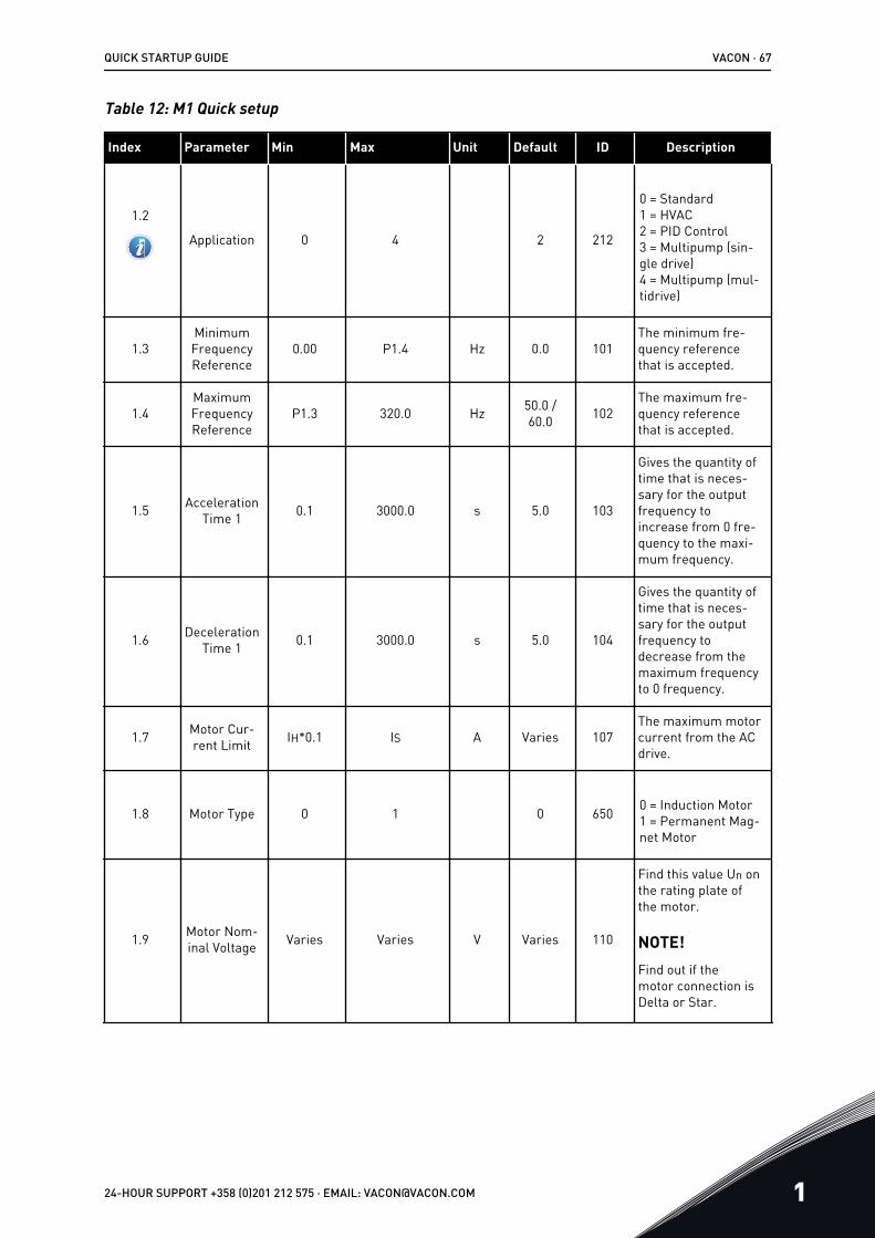
Table 12: M1 Quick setup
Index Parameter Min Max Unit Default ID Description
1.2
Application 0 4 2 212
0 = Standard1 = HVAC2 = PID Control3 = Multipump (sin-gle drive)4 = Multipump (mul-tidrive)
1.3MinimumFrequencyReference
0.00 P1.4 Hz 0.0 101The minimum fre-quency referencethat is accepted.
1.4MaximumFrequencyReference
P1.3 320.0 Hz 50.0 /60.0 102
The maximum fre-quency referencethat is accepted.
1.5 AccelerationTime 1 0.1 3000.0 s 5.0 103
Gives the quantity oftime that is neces-sary for the outputfrequency toincrease from 0 fre-quency to the maxi-mum frequency.
1.6 DecelerationTime 1 0.1 3000.0 s 5.0 104
Gives the quantity oftime that is neces-sary for the outputfrequency todecrease from themaximum frequencyto 0 frequency.
1.7 Motor Cur-rent Limit IH*0.1 IS A Varies 107
The maximum motorcurrent from the ACdrive.
1.8 Motor Type 0 1 0 650 0 = Induction Motor1 = Permanent Mag-net Motor
1.9 Motor Nom-inal Voltage Varies Varies V Varies 110
Find this value Un onthe rating plate ofthe motor.
NOTE!Find out if themotor connection isDelta or Star.
QUICK STARTUP GUIDE VACON · 67
24-HOUR SUPPORT +358 (0)201 212 575 · EMAIL: [email protected] 1

Table 12: M1 Quick setup
Index Parameter Min Max Unit Default ID Description
1.10Motor Nom-
inal Fre-quency
8.0 320.0 Hz 50.0 /60.0 111
Find this value fn onthe rating plate ofthe motor.
1.11 Motor Nom-inal Speed 24 19200 Rpm Varies 112
Find this value nn onthe rating plate ofthe motor.
1.12 Motor Nom-inal Current IH * 0.1 IS A Varies 113
Find this value In onthe rating plate ofthe motor.
1.13Motor CosPhi (Power
Factor)0.30 1.00 Varies 120
Find this value on therating plate of themotor.
1.14 Energy Opti-misation 0 1 0 666
The drive finds theminimum motor cur-rent to use lessenergy and to lowerthe motor noise. Usethis function with, forexample, fan andpump processes.
0 = Disabled1 = Enabled
1.15 Identifica-tion 0 2 0 631
The identification runcalculates or meas-ures the motorparameters that arenecessary for a goodcontrol of the motorand speed.
0 = No action1 = At standstill2 = With rotation
Before you do theidentification run,you must set themotor nameplateparameters.
1.16 Start Func-tion 0 1 0 505 0 = Ramping
1 = Flying Start
1.17 Stop Func-tion 0 1 0 506 0 = Coasting
1 = Ramping
VACON · 68 QUICK STARTUP GUIDE
1 TEL. +358 (0)201 2121 · FAX +358 (0)201 212 205

Table 12: M1 Quick setup
Index Parameter Min Max Unit Default ID Description
1.18 AutomaticReset 0 1 0 731 0 = Disabled
1 = Enabled
1.19Response to
ExternalFault
0 3 2 701
0 = No action1 = Alarm2 = Fault (Stopaccording to stopmode)3 = Fault (Stop bycoasting)
1.20 Response toAI Low Fault 0 5 0 700
0 = No action1 = Alarm2 = Alarm+presetfault frequency(P3.9.1.13)3 = Alarm + previousfrequency4 = Fault (stopaccording to stopmode)5 = Fault (stop bycoasting)
1.21RemoteControlPlace
0 1 0 172
The selection of theremote control place(start/stop).
0 = I/O control1 = Fieldbus control
QUICK STARTUP GUIDE VACON · 69
24-HOUR SUPPORT +358 (0)201 212 575 · EMAIL: [email protected] 1

Table 12: M1 Quick setup
Index Parameter Min Max Unit Default ID Description
1.22I/O Control
Reference ASelection
1 20 6 117
The selection of thefrequency referencesource when thecontrol place is I/O A.
0 = PC1 = Preset Fre-quency 02= Keypad Reference3 = Fieldbus4 = AI15 = AI26 = AI1+AI27 = PID Reference8 = Motor Potenti-ometer11 = Block Out.112 = Block Out.213 = Block Out.314 = Block Out.415 = Block Out.516 = Block Out.617 = Block Out.718 = Block Out.819 = Block Out.920 = Block Out.10
The application thatyou set with parame-ter 1.2 gives thedefault value.
1.23
Keypad Con-trol Refer-
ence Selec-tion
1 20 1 121
See P1.22.
1.24
FieldbusControl Ref-
erenceSelection
1 20 2 122
See P1.22.
1.25 AI1 SignalRange 0 1 0 379 0= 0..10V / 0..20mA
1= 2..10V / 4..20mA
1.26 AI2 SignalRange 0 1 1 390 0= 0..10V / 0..20mA
1= 2..10V / 4..20mA
1.27 RO1 Func-tion 0 51 2 11001 See P3.5.3.2.1
VACON · 70 QUICK STARTUP GUIDE
1 TEL. +358 (0)201 2121 · FAX +358 (0)201 212 205

Table 12: M1 Quick setup
Index Parameter Min Max Unit Default ID Description
1.28 RO2 Func-tion 0 51 3 11004 See P3.5.3.2.1
1.29 RO3 Func-tion 0 51 1 11007 See P3.5.3.2.1
1.30 AO1 Func-tion 0 31 2 10050 See P3.5.4.1.1
QUICK STARTUP GUIDE VACON · 71
24-HOUR SUPPORT +358 (0)201 212 575 · EMAIL: [email protected] 1

Table 13: M1.35 Multipump (Multidrive)
Index Parameter Min Max Unit Default ID Description
1.35.1 PID Gain 0.00 100.00 % 100.00 118
If the value of theparameter is set to100%, a change of10% in the errorvalue causes thecontroller output tochange by 10%.
1.35.2 PID IntegrationTime 0.00 600.00 s 1.00 119
If this parameter isset to, 1,00 s, achange of 10% inthe error valuecauses the control-ler output tochange by10.00%/s.
1.35.3 PID DerivationTime 0.00 100.00 s 0.00 1132
If this parameter isset to 1,00 s, achange of 10% inthe error valueduring 1.00 s cau-ses the controlleroutput to change by10.00%.
1.35.4 Process UnitSelection 1 44 1 1036
Select the unit ofthe process. SeeP3.13.1.4
1.35.5 Process Unit Min Varies Varies Varies 1033
The process unitvalue that is thesame as 0% of thePID feedback sig-nal.
1.35.6 Process UnitMax Varies Varies Varies 1034
The process unitvalue that is thesame as 100% ofthe PID feedbacksignal.
1.35.7 Feedback 1Source Selection 0 30 2 334 See P3.13.3.3
1.35.8 Setpoint 1Source Selection 0 32 1 332 See P3.13.2.6
1.35.9 Keypad Setpoint1 Varies Varies Varies 0 167
VACON · 72 QUICK STARTUP GUIDE
1 TEL. +358 (0)201 2121 · FAX +358 (0)201 212 205

Table 13: M1.35 Multipump (Multidrive)
Index Parameter Min Max Unit Default ID Description
1.35.10 Sleep FrequencyLimit 1 0.0 320.0 Hz 0.0 1016
The drive goes tothe sleep modewhen the outputfrequency staysbelow this limit forlonger than isspecified byparameter SleepDelay.
1.35.11 Sleep Delay 1 0 3000 s 0 1017
The minimumquantity of timethat the frequencystays below thesleep level beforethe drive stops.
1.35.12 Wake-up Level 1 Varies Varies Varies Varies 1018
The wake-up valueof the PID feedbacksupervision. Wake-up Level 1 uses theselected processunits.
1.35.13 Multipump Mode 0 2 0 1785
Selects the Multi-pump mode.
0 = Single drive1 = Multifollower2 = Multimaster
1.35.14 Number ofPumps 1 8 1 1001
Total number ofmotors (pumps/fans) used in theMultipump system.
1.35.15 Pump ID Num-ber 1 8 1 1500
The order numberof the drive in thepump system. Thisparameter is onlyused in multifol-lower or multimas-ter modes.
QUICK STARTUP GUIDE VACON · 73
24-HOUR SUPPORT +358 (0)201 212 575 · EMAIL: [email protected] 1

Table 13: M1.35 Multipump (Multidrive)
Index Parameter Min Max Unit Default ID Description
1.35.16 Start and Feed-back Signals 0 2 1 1782
Use this parameterto select if the startsignal and/or thePIDfeedback sig-nals are connectedto the drive.
0 = Not connected1 = Only Start Sig-nal Connected2 = Both SignalsConnected
1.35.17 Pump Interlock-ing 0 1 1 1032
Enable/Disableinterlocks. Inter-locks tell the sys-tem if a motor isconnected or not.
0 = Disabled1 = Enabled
1.35.18
Autochange 0 1 1 1027
Disable/enable therotation of the startorder and the pri-ority of the motors.
0 = Disabled1 = Enabled (inter-val)
1.35.19 AutochangedPump 0 1 1 1028 0 = Auxiliary Pump
1 = All Pumps
1.35.20 AutochangeInterval 0.0 3000.0 h 48.0 1029
When the timespecified by thethis parameter isused, the autoch-ange functionstarts. But theautochange startsonly if the capacityis below the levelspecified byparametersP3.35.23 andP3.35.24.
1.35.21 Autochange Days 0 127 1786 Range: Monday toSunday
VACON · 74 QUICK STARTUP GUIDE
1 TEL. +358 (0)201 2121 · FAX +358 (0)201 212 205

Table 13: M1.35 Multipump (Multidrive)
Index Parameter Min Max Unit Default ID Description
1.35.22 Autochange Timeof Day Time 1787 Range: 00:00:00 to
23:59:59
1.35.23 Autochange:Frequency Limit 0.00 P3.3.1.2 Hz 25:00 1031 These parameters
set the level belowwhich the capacitymust stay for theautochange tostart.
1.35.24 Autochange:Pump Limit 1 6 1030
1.35.25 Bandwidth 0 100 % 10 1097
When the feedbackvalue staysbetween 4.5 and .5.5 bar, the motorstays connected.
Setpoint = 5 barBandwidth = 10%
When the feedbackvalue staysbetween 4.5 and5.5 bar, the motorstays connected.
1.35.26 Bandwidth Delay 0 3600 s 10 1098
When the feedbackis outside thebandwidth, thetime after whichpumps are addedor removed.
1.35.27 Constant Pro-duction Speed 0 100 % 100 1513
Gives the constantspeed at which thepump locks, whenthe pump goes tothe maximum fre-quency. The nextpump starts theregulation in themultimaster mode.
1.35.28 Pump 1 Interlock DigINSlot0.1 426 OPEN = Not active
CLOSED = Active
1.35.29 Flushing Refer-ence
Maximumreference
Maximumreference HZ 50.00 1239
Gives the frequencyreference when theflush function isactivated.
QUICK STARTUP GUIDE VACON · 75
24-HOUR SUPPORT +358 (0)201 212 575 · EMAIL: [email protected] 1

2 WIZARDS2.1 STANDARD APPLICATION WIZARD
The application wizard helps you to set the basic parameters that are related to theapplication.
To start the Standard application wizard, set the value Standard to parameter P1.2Application (ID 212) in the keypad.
NOTE!
If you start the Standard application wizard from the Startup wizard, the wizardgoes directly to step 11.
1Set a value for P3.1.2.2 Motor Type (so that it agreeswith the nameplate of the motor) PM motor
Induction motor
2 Set a value for P3.1.1.1 Motor Nominal Voltage (sothat it agrees with the nameplate of the motor)
Range: Varies
3 Set a value for P3.1.1.2 Motor Nominal Frequency(so that it agrees with the nameplate of the motor)
Range: 8.00-320.00 Hz
4 Set a value for P3.1.1.3 Motor Nominal Speed (sothat it agrees with the nameplate of the motor)
Range: 24-19200 rpm
5 Set a value for P3.1.1.4 Motor Nominal Current (sothat it agrees with the nameplate of the motor)
Range: Varies
Step 6 shows only, if you selected Induction Motor in step 1.
6 Set a value for P3.1.1.5 Motor Cos Phi Range: 0.30-1.00
7 Set a value for P3.3.1.1 Minimum Frequency Refer-ence
Range: 0.00-P3.3.1.2 Hz
8 Set value for P3.3.1.2 Maximum Frequency Refer-ence
Range: P3.3.1.1-320.00 Hz
9 Set a value for P3.4.1.2 Acceleration Time 1 Range: 0.1-3000.0 s
10 Set value for P3.4.1.3 Deceleration Time 1 Range: 0.1-3000.0 s
11
Select the control place that gives the drive thestart or stop commands and the frequency refer-ence.
I/O TerminalFieldbusKeypad
The Standard application wizard is completed.
VACON · 76 WIZARDS
2 TEL. +358 (0)201 2121 · FAX +358 (0)201 212 205

2.2 HVAC APPLICATION WIZARD
The application wizard helps you to set the basic parameters that are related to theapplication.To start the HVAC application wizard, set the value HVAC to parameter P1.2 Application (ID212) in the keypad.
1
Select the type or process (or application) that youcontrol. Compressor
FanPumpOther
Some parameters have preset values specified by the selection you made in step 1. See theparameters and their values at the end of this chapter in Table 14.
2 Set a value for P3.2.11 Restart Delay. Range: 0-20 min
Step 2 shows only if you selected Compressor in step 1.
3Set a value for P3.1.2.2 Motor Type (so that it agreeswith the nameplate of the motor) PM motor
Induction motor
4 Set a value for P3.1.1.1 Motor Nominal Voltage (sothat it agrees with the nameplate of the motor)
Range: Varies
5 Set a value for P3.1.1.2 Motor Nominal Frequency(so that it agrees with the nameplate of the motor)
Range: 8.00-320.00 Hz
6 Set a value for P3.1.1.3 Motor Nominal Speed (sothat it agrees with the nameplate of the motor)
Range: 24-19200 rpm
7 Set a value for P3.1.1.4 Motor Nominal Current (sothat it agrees with the nameplate of the motor)
Range: Varies
8 Set a value for P3.1.1.5 Motor Cos Phi (so that itagrees with the nameplate of the motor)
Range: 0.30-1.00
Step 8 shows only if you selected Induction Motor in step 3.
9 Set a value for P3.3.1.1 Minimum Frequency Refer-ence
Range: 0.00-3.3.1.2 Hz
10 Set a value for P3.3.1.2 Maximum Frequency Refer-ence
Range: P3.3.1.1-320.00 Hz
Steps 11 and 12 show only if you selected Other in step 1.
WIZARDS VACON · 77
24-HOUR SUPPORT +358 (0)201 212 575 · EMAIL: [email protected] 2

11 Set a value for P3.4.1.2 Acceleration Time 1 Range: 0.1-3000.0 s
12 Set a value for P3.4.1.3 Deceleration Time 1 Range: 0.1-3000.0 s
Next the wizard goes to steps that are specified by the application.
13
Select the control place (where you give the startand stop commands and the frequency reference) I/O Terminal
FieldbusKeypad
The HVAC application wizard is completed.
Table 14: Preset values of parameters
Index ParameterProcess type
Pump Fan Compressor
P3.1.4.1 U/f Ratio Linear Squared Linear
P3.2.4 Start Function Ramping Flying start Ramping
P3.2.5 Stop Function Ramping Coasting Ramping
P3.4.1.2 Acceleration Time 5.0 s 30.0 s 3.0 s
P3.4.1.3 Deceleration Time 5.0 s 30.0 s 3.0 s
2.3 PID CONTROL APPLICATION WIZARD
The application wizard helps you to set the basic parameters that are related to theapplication.
To start the PID control application wizard, set the value PID control to parameter P1.2Application (ID 212) in the keypad.
NOTE!
If you start the application wizard from the Startup wizard, the wizard goes directlyto step 11.
VACON · 78 WIZARDS
2 TEL. +358 (0)201 2121 · FAX +358 (0)201 212 205

1Set a value for P3.1.2.2 Motor Type (so that it agreeswith the nameplate of the motor) PM motor
Induction motor
2 Set a value for P3.1.1.1 Motor Nominal Voltage (sothat it agrees with the nameplate of the motor)
Range: Varies
3 Set a value for P3.1.1.2 Motor Nominal Frequency(so that it agrees with the nameplate of the motor)
Range: 8.00…320.00 Hz
4 Set a value for P3.1.1.3 Motor Nominal Speed (sothat it agrees with the nameplate of the motor)
Range: 24…19200 rpm
5 Set a value for P3.1.1.4 Motor Nominal Current (sothat it agrees with the nameplate of the motor)
Range: Varies
Step 6 shows only, if you selected Induction Motor in step 1.
6 Set a value for P3.1.1.5 Motor Cos Phi Range: 0.30-1.00
7 Set a value for P3.3.1.1 Minimum Frequency Refer-ence
Range: 0.00-P3.3.1.2 Hz
8 Set value for P3.3.1.2 Maximum Frequency Refer-ence
Range: P3.3.1.1-320.00 Hz
9 Set a value for P3.4.1.2 Acceleration Time 1 Range: 0.1-3000.0 s
10 Set value for P3.4.1.3 Deceleration Time 1 Range: 0.1-3000.0 s
11
Make a selection of a control place (where you givethe start and stop commands and the frequencyreference)
I/O TerminalFieldbusKeypad
12 Set a value for P3.13.1.4 Process Unit Selection More than 1 selection
If your selection is other than %, you see the next questions. If your selection is %, the wizardgoes directly to step 16.
13 Set a value for P3.13.1.5 Process Unit Min The range is specified by the selection in step12.
14 Set a value for P3.13.1.6 Process Unit Max The range is specified by the selection in step12.
15 Set a value for P3.13.1.7 Process Unit Decimals Range: 0-4
16 Set a value for P3.13.3.3 Feedback 1 Source Selec-tion
See the table Feedback settings in Table 74 Feedback settings
If you make a selection of an analogue input signal, you see step 18. With other selections,the wizard goes to step 19.
WIZARDS VACON · 79
24-HOUR SUPPORT +358 (0)201 212 575 · EMAIL: [email protected] 2

17Set the signal range of the analogue input
0 = 0-10V / 0-20mA1 = 2-10V / 4-20mA
18Set a value for P3.13.1.8 Error Inversion
0 = Normal1 = Inverted
19 Set a value for P3.13.2.6 Setpoint Source Selection See table Setpoints in Table 74 Feedback set-tings
If you select an analogue input signal, step 21 shows. With other selections, the wizard goesto step 23.
If you set Keypad Setpoint 1 or Keypad Setpoint 2 as the value, the wizard goes directly to step22.
20Set the signal range of the analogue input
0 = 0-10V / 0-20mA1 = 2-10V / 4-20mA
21 Set a value for P3.13.2.1 (Keypad Setpoint 1) andP3.13.2.2 (Keypad Setpoint 2)
Specified by the range set in step 20
22Use the sleep function
0 = No1 = Yes
If you give the value Yes for the question 22, you see the next 3 questions. If you give the valueNo, the wizard is completed.
23 Set a value for P3.13.5.1 Sleep Frequency Limit Range: 0.00-320.00 Hz
24 Set a value for P3.13.5.2 Sleep Delay 1 Range: 0-3000 s
25 Set a value for P3.13.5.3 Wake-up Level The range is specified by the set processunit.
The PID control application wizard is completed.
2.4 MULTIPUMP (SINGLE DRIVE) APPLICATION WIZARD
The application wizard helps you to set the basic parameters that are related to theapplication.
To start the Multipump (single drive) application wizard, set the value Multipump (Single drive)to parameter P1.2 Application (ID 212) in the keypad.
NOTE!
If you start the application wizard from the Startup wizard, the wizard goes directlyto step 11.
VACON · 80 WIZARDS
2 TEL. +358 (0)201 2121 · FAX +358 (0)201 212 205

1Set a value for P3.1.2.2 Motor Type (so that it agreeswith the nameplate of the motor) PM motor
Induction motor
2 Set a value for P3.1.1.1 Motor Nominal Voltage (sothat it agrees with the nameplate of the motor)
Range: Varies
3 Set a value for P3.1.1.2 Motor Nominal Frequency(so that it agrees with the nameplate of the motor)
Range: 8.00-320.00 Hz
4 Set a value for P3.1.1.3 Motor Nominal Speed (sothat it agrees with the nameplate of the motor)
Range: 24-19200 rpm
5 Set a value for P3.1.1.4 Motor Nominal Current (sothat it agrees with the nameplate of the motor)
Range: Varies
Step 6 shows only, if you selected Induction Motor in step 1.
6 Set a value for P3.1.1.5 Motor Cos Phi Range: 0.30-1.00
7 Set a value for P3.3.1.1 Minimum Frequency Refer-ence
Range: 0.00-P3.3.1.2 Hz
8 Set value for P3.3.1.2 Maximum Frequency Refer-ence
Range: P3.3.1.1-320.00 Hz
9 Set a value for P3.4.1.2 Acceleration Time 1 Range: 0.1-3000.0 s
10 Set value for P3.4.1.3 Deceleration Time 1 Range: 0.1-3000.0 s
11
Make a selection of a control place (where you givethe start and stop commands and the frequencyreference)
I/O TerminalFieldbusKeypad
12 Set a value for P3.13.1.4 Process Unit Selection More than 1 selection
If your selection is other than %, you see the next 3 steps. If your selection is %, the wizardgoes directly to step 16.
13 Set a value for P3.13.1.5 Process Unit Min The range is specified by the selection in step12.
14 Set a value for P3.13.1.6 Process Unit Max The range is specified by the selection in step12.
15 Set a value for P3.13.1.7 Process Unit Decimals Range: 0-4
16 Set a value for P3.13.3.3 Feedback 1 Source Selec-tion
See the table Feedback settings in Table 74 Feedback settings
If you make a selection of an analogue input signal, you see step 17. With other selections,the wizard goes to step 18.
WIZARDS VACON · 81
24-HOUR SUPPORT +358 (0)201 212 575 · EMAIL: [email protected] 2

17Set the signal range of the analogue input
0 = 0-10V / 0-20mA1 = 2-10V / 4-20mA
18Set a value for P3.13.1.8 Error Inversion
0 = Normal1 = Inverted
19 Set a value for P3.13.2.6 Setpoint Source Selection See table Setpoints in Table 73 Setpoint set-tings
If you select an analogue input signal, step 20 shows first, and then step 22 shows. Withother selections, the wizard goes to step 21.
If you set Keypad Setpoint 1 or Keypad Setpoint 2 as the value, the wizard goes directly to step22.
20Set the signal range of the analogue input
0 = 0-10V / 0-20mA1 = 2-10V / 4-20mA
21 Set a value for P3.13.2.1 (Keypad Setpoint 1) andP3.13.2.2 (Keypad Setpoint 2)
Specified by the range set in step 19
22Use the sleep function
0 = No1 = Yes
If you give the value Yes in step 22, you see the next 3 steps. If you give the value No, thewizard goes to step 26.
23 Set a value for P3.13.5.1 Sleep Frequency Limit Range: 0.00-320.00 Hz
24 Set a value for P3.13.5.2 Sleep Delay 1 Range: 0-3000 s
25 Set a value for P3.13.5.3 Wake-up Level The range is specified by the set processunit.
26 Set a value for P3.15.2 Number of pumps Range: 1-8
27Set a value for P3.15.5 Pump Interlocking
0 = Not used1 = Enabled
28
Set a value for P3.15.6 Autochange0 = Disabled1 = Enabled (Interval)2 = Enabled (Real Time)
If you set the value Enabled (Interval or Real Time) to parameter Autochange, steps 29-34show. If you set the value Disabled to parameter Autochange, the wizard goes directly to step35.
VACON · 82 WIZARDS
2 TEL. +358 (0)201 2121 · FAX +358 (0)201 212 205

29Set a value for P3.15.7 Autochanged pumps
0 = Auxiliary pumps1 = All pumps
Step 30 shows only if you set the value Enabled (Interval) to parameter Autochange in step 28.
30 Set a value for P3.15.8 Autochange Interval Range: 0-3000 s
Steps 31 and 32 show only if you set the value Enabled (Real Time) to parameter Autochangein step 28.
31 Set a value for P3.15.9 Autochange Days Range: Monday to Sunday
32 Set a value for P3.15.10 Autochange Time of Day Range: 00:00:00 to 23:59:59
33 Set a value for P3.15.11 Autochange FrequencyLimit
Range: P3.3.1.1-P3.3.1.2 Hz
34 Set a value for P3.15.12 Autochange Pump Limit Range: 1-8
35 Set a value for P3.15.13 Bandwidth Range: 0-100%
36Set a value for P3.15.14 Bandwidth Delay
Range: 0-3600 s
The Multipump (single drive) application wizard is completed.
2.5 MULTIPUMP (MULTIDRIVE) APPLICATION WIZARD
The application wizard helps you to set the basic parameters that are related to theapplication.
To start the Multipump (multidrive) application wizard, set the value Multipump (Multidrive) toparameter P1.2 Application (ID 212) in the keypad.
NOTE!
If you start the application wizard from the Startup wizard, the wizard goes directlyto step 11.
WIZARDS VACON · 83
24-HOUR SUPPORT +358 (0)201 212 575 · EMAIL: [email protected] 2

1Set a value for P3.1.2.2 Motor Type (so that it agreeswith the nameplate of the motor) PM motor
Induction motor
2 Set a value for P3.1.1.1 Motor Nominal Voltage (sothat it agrees with the nameplate of the motor)
Range: Varies
3 Set a value for P3.1.1.2 Motor Nominal Frequency(so that it agrees with the nameplate of the motor)
Range: 8.00-320.00 Hz
4 Set a value for P3.1.1.3 Motor Nominal Speed (sothat it agrees with the nameplate of the motor)
Range: 24-19200 rpm
5 Set a value for P3.1.1.4 Motor Nominal Current (sothat it agrees with the nameplate of the motor)
Range: Varies
Step 6 shows only, if you selected Induction Motor in step 1.
6 Set a value for P3.1.1.5 Motor Cos Phi Range: 0.30-1.00
7 Set a value for P3.3.1.1 Minimum Frequency Refer-ence
Range: 0.00-P3.3.1.2 Hz
8 Set value for P3.3.1.2 Maximum Frequency Refer-ence
Range: P3.3.1.1-320.00 Hz
9 Set a value for P3.4.1.2 Acceleration Time 1 Range: 0.1-3000.0 s
10 Set value for P3.4.1.3 Deceleration Time 1 Range: 0.1-3000.0 s
11
Make a selection of a control place (where you givethe start and stop commands and the frequencyreference)
I/O TerminalFieldbusKeypad
12 Set a value for P3.13.1.4 Process Unit Selection More than 1 selection
If your selection is other than %, you see the next 3 steps. If your selection is %, the wizardgoes directly to step 16.
13 Set a value for P3.13.1.5 Process Unit Min The range is specified by the selection in step12.
14 Set a value for P3.13.1.6 Process Unit Max The range is specified by the selection in step12.
15 Set a value for P3.13.1.7 Process Unit Decimals Range: 0-4
16 Set a value for P3.13.3.3 Feedback 1 Source Selec-tion
See the table Feedback settings in ChapterTable 73 Setpoint settings
If you make a selection of an analogue input signal, you see step 17. With other selections,the wizard goes to step 18.
VACON · 84 WIZARDS
2 TEL. +358 (0)201 2121 · FAX +358 (0)201 212 205

17Set the signal range of the analogue input
0 = 0-10V / 0-20mA1 = 2-10V / 4-20mA
18Set a value for P3.13.1.8 Error Inversion
0 = Normal1 = Inverted
19 Set a value for P3.13.2.6 Setpoint Source Selection See table Setpoints in Chapter Table 73 Set-point settings
If you select an analogue input signal, step 20 shows first, and then step 22 shows. Withother selections, the wizard goes to step 21.
If you set Keypad Setpoint 1 or Keypad Setpoint 2 as the value, the wizard goes directly to step22.
20Set the signal range of the analogue input
0 = 0-10V / 0-20mA1 = 2-10V / 4-20mA
21 Set a value for P3.13.2.1 (Keypad Setpoint 1) andP3.13.2.2 (Keypad Setpoint 2)
Specified by the range set in step 19
22Use the sleep function
0 = No1 = Yes
If you give the value Yes in step 22, you see the next 3 steps. If you give the value No, thewizard goes to step 26.
WIZARDS VACON · 85
24-HOUR SUPPORT +358 (0)201 212 575 · EMAIL: [email protected] 2

23 Set a value for P3.13.5.1 Sleep Frequency Limit Range: 0.00-320.00 Hz
24 Set a value for P3.13.5.2 Sleep Delay 1 Range: 0-3000 s
25 Set a value for P3.13.5.3 Wake-up Level The range is specified by the set processunit.
26Set a value for P3.15.1 Multipump Mode
MultifollowerMultimaster
27 Set a value for P3.15.3 Pump ID Number Range: 1-8
28
Set a value for P3.15.4 Start and Feedback0 = Not connected1 = Only Start Signal Connected2 = Both Signals Connected
29 Set a value for P3.15.2 Number of pumps Range: 1-8
30Set a value for P3.15.5 Pump Interlocking
0 = Not used1 = Enabled
31
Set a value for P3.15.6 Autochange0 = Disabled1 = Enabled (Interval)2 = Enabled (Weekdays)
If you set the value Enabled (Interval) to parameter Autochange, step 33 shows. If you set thevalue Enabled (Weekdays) to parameter Autochange, step 34 shows. If you set the valueDisabled to parameter Autochange, the wizard goes directly to step 36.
32Set a value for P3.15.7 Autochanged pumps
0 = Auxiliary pumps1 = All pumps
Step 33 shows only if you set the value Enabled (Interval) to parameter Autochange in step 31.
33 Set a value for P3.15.8 Autochange Interval Range: 0-3000 h
Steps 34 and 35 show only if you set the value Enabled (Weekdays) to parameter Autochangein step 31.
VACON · 86 WIZARDS
2 TEL. +358 (0)201 2121 · FAX +358 (0)201 212 205

34 Set a value for P3.15.9 Autochange Days Range: Monday to Sunday
35 Set a value for P3.15.10 Autochange Time of Day Range: 00:00:00 to 23:59:59
36 Set a value for P3.15.13 Bandwidth Range: 0-100%
37Set a value for P3.15.14 Bandwidth Delay
Range: 0-3600 s
The Multipump (multidrive) application wizard is completed.
2.6 FIRE MODE WIZARD
To start the Fire mode wizard, make the selection Activate for parameter 1.1.2 in the Quicksetup menu.
CAUTION!
Before you continue, read about the password and warranty in Chapter 10.13 Fire mode.
1 Set a value for parameter P3.17.2 Fire Mode Fre-quency Source
More than 1 selection
If you set a value other than Fire mode frequency, the wizard goes directly to step 3.
2 Set a value for parameter P3.17.3 Fire Mode Fre-quency
Range: varies
3Activate the signal when the contact opens or whenit closes 0 = Open contact
1 = Closed contact
If you set the value Open contact in step 3, the wizard goes directly to step 5. If you set thevalue Closed contact in step 3, step 5 is unnecessary.
WIZARDS VACON · 87
24-HOUR SUPPORT +358 (0)201 212 575 · EMAIL: [email protected] 2

4Set a value for parameters P3.17.4 Fire Mode Acti-vation on OPEN / P3.17.5 Fire Mode Activation onCLOSE
Make a selection of a digital input to activateFire mode. See also Chapter 10.5.1 Program-ming of digital and analogue inputs.
5
Set a value for parameter P3.17.6 Fire ModeReverse
Make a selection of a digital input to activatethe reverse direction in Fire mode.
DigIn Slot0.1 = FORWARDDigIn Slot0.2 = REVERSE
6
Set a value for P3.17.1 Fire Mode Password Set a password to enable the Fire mode func-tion.
1234 = Enable test mode1002 = Enable Fire mode
The Fire mode wizard is completed.
VACON · 88 WIZARDS
2 TEL. +358 (0)201 2121 · FAX +358 (0)201 212 205

3 USER INTERFACES3.1 NAVIGATION ON THE KEYPAD
The data of the AC drive is in menus and submenus. To move between the menus, use thearrow buttons Up and Down in the keypad. To go into a group or an item, push the OK button.To go back to the level where you were before, push the Back/Reset button.
On the display, you see your current location in the menu, for example M3.2.1. You also seethe name of the group or item in your current location.
USER INTERFACES VACON · 89
24-HOUR SUPPORT +358 (0)201 212 575 · EMAIL: [email protected] 3

Mai
n m
enu
Sub
men
usSub
men
usSub
men
usM
ain
men
uM
ain
men
u
M2
Mon
itor
M1
Qu
ick
setu
pM
1.1
Wiz
ards
(C
onte
nt d
epen
ds
on P
1.2,
App
sel
ect.
)
M2.
1 M
ultim
onito
r
M3.
1 M
otor
Set
tings
M3.
2 Sta
rt/S
top
Set
up
M3.
3 Re
fere
nces
M3.
4 Ra
mps
and
Bra
kes
M3.
5 I/
O C
onfig
urat
ion
M3.
6 FB
Dat
a M
appi
ng
M3.
10
Aut
omat
ic R
eset
M3.
11
App
l. se
ttin
gsM
3.12
Tim
er F
unct
ions
M3.
19
Drive
Cus
tom
izer
M3.
13 P
ID C
ontr
olle
r
M3.
14 E
xt P
ID C
trl
M3.
15 M
ulti-
Pum
p
M3.
16 M
aint
en.
cntr
s
M3.
17 F
ire
Mod
e
M3.
21 P
ump
Con
trol
M3.
18 M
otor
Pre
heat
M3.
7 Pr
ohib
it Fr
eq
M3.
8 Sup
ervi
sion
s
M3.
9 Pr
otec
tions
M2.
2 Tr
end
Cur
ve
M2.
3 Bas
ic
M2.
4 I/
O
M2.
5 Te
mpe
rat.
inpu
tsM
2.6
Extr
as/A
dvan
ced
M2.
7 Ti
mer
Fun
ctio
nsM
2.8
PID
Con
trol
ler
M2.
9 Ex
t PI
D C
ontr
olle
rM
2.10
Mul
ti-Pu
mp
M2.
11 M
aint
en.c
ount
.
M2.
12 F
ield
bus
data
M3
P
aram
eter
s
M8
U
ser
Leve
ls
M7
Fa
vou
rite
s
M4
Dia
gn
osti
cs
M5
I/
O a
nd
H
ard
war
e
M6
Use
r S
etti
ng
s
M4.
4 To
tal C
ount
ers
M4.
5 Tr
ip C
ount
ers
M4.
6 Sof
twar
e In
fo
M5.
1 Bas
ic I
/OM
5.2.
..M
5.4
Slo
ts C
,D,E
M5.
5 Re
al T
ime
Clo
ck
M5.
6 Po
wer
uni
t se
tt.
M5.
8 RS-4
85
M5.
9 Et
hern
et
M6.
1 La
ngua
ge s
elec
t.M
6.5
Para
met
er B
acku
pM
6.6
Para
met
er C
omp.
M6.
7 D
rive
Nam
e
M8.
1 U
ser
Leve
l
M8.
2 Acc
ess
Cod
e
Fig. 32: The basic menu structure of the AC drive
VACON · 90 USER INTERFACES
3 TEL. +358 (0)201 2121 · FAX +358 (0)201 212 205

3.2 USING THE GRAPHICAL DISPLAY
STOP READY I/O
Main Menu
A B C D E
F
H
GQuick Setup( 17 )Monitor( 5 )
Parameters( 12 )
M1ID:
Fig. 33: The main menu of the graphical displayA. The first status field: STOP/RUNB. The rotation directionC. The second status field: READY/NOT
READY/FAULTD. The alarm field: ALARM/-E. The control place: PC/IO/KEYPAD/
FIELDBUS
F. The location field: the parameter IDnumber and the current location in themenu
G. An activated group or item: push OK togo in
H. The number of items in the group inquestion
3.2.1 EDITING THE VALUESOn the graphical display, there are 2 different procedures to edit the value of an item.
Usually, you can set only 1 value for a parameter. Select from a list of text values or from arange of numerical values.
CHANGING THE TEXT VALUE OF A PARAMETER1 Find the parameter with the arrow buttons.
STOP READY I/O
Rem Control PlaceI/O Control
KeypadStopButtonYes
Start FunctionRamping
Start / Stop SetupM3.2.1ID:172
USER INTERFACES VACON · 91
24-HOUR SUPPORT +358 (0)201 212 575 · EMAIL: [email protected] 3

2 To go to the Edit mode, push the OK button 2 timesor push the arrow button Right. STOP READY I/O
Rem Control PlaceM3.2.1ID:
Edit
Help
Add to favourites
3 To set a new value, push the arrow buttons Up andDown. STOP READY I/O
Rem Control PlaceM3.2.1ID:
FieldbusCTRL
I/O Control
4 To accept the change, push the OK button. Toignore the change, use the Back/Reset button.
EDITING THE NUMERICAL VALUES1 Find the parameter with the arrow buttons.
STOP READY I/O
Frequency RefP3.3.1.1ID:101
MaxFreqReference0.00 Hz
MinFreqReference50.00 Hz
PosFreqRefLimit320.00 Hz
2 Go to the Edit mode.STOP READY I/O
MinFreqReferenceP3.3.1.1ID:101
0.00 Hz
Min: 0.00HzMax: 50.00Hz
VACON · 92 USER INTERFACES
3 TEL. +358 (0)201 2121 · FAX +358 (0)201 212 205

3 If the value is numerical, move from digit to digitwith the arrow buttons Left and Right. Change thedigits with the arrow buttons Up and Down.
STOP READY I/O
MinFreqReferenceP3.3.1.1ID:101
00.00 Hz
Min: 0.00HzMax: 50.00Hz
4 To accept the change, push the OK button. Toignore the change, go back to the level where youwere before with the Back/Reset button.
STOP READY I/O
MinFreqReferenceP3.3.1.1ID:101
11.00 Hz
Min: 0.00HzMax: 50.00Hz
THE SELECTION OF MORE THAN 1 VALUESome parameters let you to make a selection of more than 1 value. Select a checkbox ateach necessary value.
1 Find the parameter. There is a symbol on thedisplay when a checkbox selection is possible. STOP READY I/O
P3.12.1.3ID:1466Interval 1
00:00:00
00:00:00ON Time
OFF Time
Days0
A
A. The symbol of the checkboxselection
USER INTERFACES VACON · 93
24-HOUR SUPPORT +358 (0)201 212 575 · EMAIL: [email protected] 3

2 To move in the list of values, use the arrow buttonsUp and Down. STOP READY I/O
M 3.12.1.3.1ID:Days
MondayTuesdayWednesday
ThursdayFriday
Sunday
3 To add a value into your selection, select the boxthat is next to it with the arrow button Right. STOP READY I/O
M 3.12.1.3.1ID:Days
MondayTuesdayWednesday
ThursdayFriday
Sunday
3.2.2 RESETTING A FAULTTo reset a fault, you can use the Reset button or the parameter Reset Faults. See theinstructions in 11.1 A fault comes into view.
3.2.3 THE FUNCT BUTTONYou can use the FUNCT button for 4 functions.
• To have an access to the Control page.• To easily change between the Local and Remote control places.• To change the rotation direction.• To quickly edit a parameter value.
The selection of the control place determines from where the AC drive takes the start andstop commands. All the control places have a parameter for the selection of the frequencyreference source. The Local control place is always the keypad. The Remote control place isI/O or Fieldbus. You can see the current control place on the status bar of the display.
It is possible to use I/O A, I/O B and Fieldbus as Remote control places. I/O A and Fieldbushave the lowest priority. You can make a selection of them with P3.2.1 (Remote ControlPlace). I/O B can bypass the Remote control places I/O A and Fieldbus with a digital input.You can make a selection of the digital input with parameter P3.5.1.7 (I/O B Control Force).
The keypad is always used as a control place when the control place is Local. Local controlhas higher priority than Remote control. For example, when you are in Remote control, ifparameter P3.5.1.7 bypasses the control place with a digital input, and you make a selectionof Local, Keypad becomes the control place. Use the FUNCT button or P3.2.2 Local/Remoteto change between the Local and Remote control.
VACON · 94 USER INTERFACES
3 TEL. +358 (0)201 2121 · FAX +358 (0)201 212 205

CHANGING THE CONTROL PLACE1 Anywhere in the menu structure, push the FUNCT
button. STOP READY Keypad
ID: M1Main Menu
Monitor( 12 )
( 21 )
( 6 )
Parameters
Diagnostics
2 To make a selection of the Local/Remote, use thearrow buttons Up and Down. Push the OK button. STOP READY Keypad
ID:1805Choose action
Control page
Change direction
Local/Remote
3 To make a selection of Local or Remote, use thearrow buttons Up and Down again. To accept theselection, push the OK button.
STOP READY Keypad
ID:211Local/Remote
RemoteLocal
4 If you changed Remote control place to Local, thatis, the keypad, give a keypad reference. STOP READY I/O
ID: M1Main Menu
( 21 )
( 6 )
Parameters( 12 )
Monitor
Diagnostics
After the selection, the display goes back into the same location where it was when youpushed the FUNCT button.
USER INTERFACES VACON · 95
24-HOUR SUPPORT +358 (0)201 212 575 · EMAIL: [email protected] 3

GOING INTO THE CONTROL PAGEIt is easy to monitor the most important values in the Control page.
1 Anywhere in the menu structure, push the FUNCTbutton. STOP READY I/O
Main Menu
( 21 )
( 6 )
Parameters( 12 )Monitor
Diagnostics
M1ID:
2 To make a selection of the Control page, push thearrow buttons Up and Down. Go in with the OKbutton. The control page opens.
STOP READY Keypad
ID:1805 Choose action
Control page
Change direction
Local/Remote
3 If you use the Local control place and the keypadreference, you can set P3.3.1.8 Keypad Referencewith the OK button.
STOP READY Keypad
ID: 184Keypad Reference
0.00Hz
Output Frequency
Motor Current
Motor Torque
Motor Power0.00Hz
0.00A
0.00%
0.00%
4 To change the digits in the value, push the arrowbuttons Up and Down. Accept the change with theOK button.
STOP READY Keypad
ID: 168Keypad Reference
0.00Hz
Output Frequency
Motor Current
Motor Torque
Motor Power0.00Hz
0.00A
0.00%
0.00%
See more information about Keypad Reference in 5.3 Group 3.3: References. If you use othercontrol places or reference values, the display shows the frequency reference, which you
VACON · 96 USER INTERFACES
3 TEL. +358 (0)201 2121 · FAX +358 (0)201 212 205

cannot edit. The other values on the page are Multimonitoring values. You can make aselection of the values that show up here (see instructions in 4.1.1 Multimonitor).
CHANGING THE ROTATION DIRECTIONYou can change the rotation direction of the motor quickly with the FUNCT button.
NOTE!
The command Change direction is available in the menu only if the current controlplace is Local.
1 Anywhere in the menu structure, push the FUNCTbutton. STOP READY I/O
ID: M1Main Menu
Monitor( 7 )
Parameters( 15 )Diagnostics( 6 )
2 To make a selection of the Change direction, pushthe arrow buttons Up and Down. Push the OKbutton.
RUN READY Keypad
ID:1805Choose action
Control pageChange direction
Local/Remote
3 Make a selection of a new rotation direction. Thecurrent rotation direction blinks. Push the OKbutton.
RUN READY Keypad
ID:1805Choose action
ForwardReverse
USER INTERFACES VACON · 97
24-HOUR SUPPORT +358 (0)201 212 575 · EMAIL: [email protected] 3
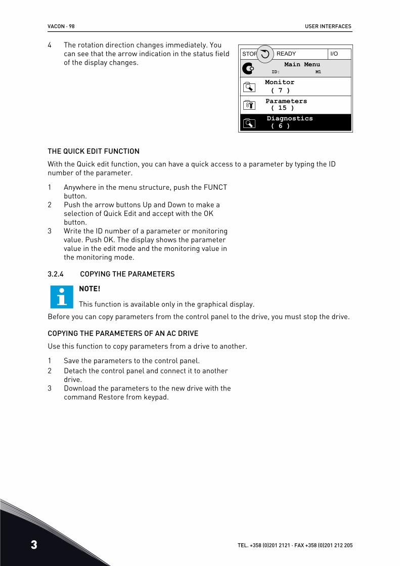
4 The rotation direction changes immediately. Youcan see that the arrow indication in the status fieldof the display changes.
STOP READY I/O
ID: M1Main Menu
Monitor( 7 )
Parameters( 15 )Diagnostics( 6 )
THE QUICK EDIT FUNCTIONWith the Quick edit function, you can have a quick access to a parameter by typing the IDnumber of the parameter.
1 Anywhere in the menu structure, push the FUNCTbutton.
2 Push the arrow buttons Up and Down to make aselection of Quick Edit and accept with the OKbutton.
3 Write the ID number of a parameter or monitoringvalue. Push OK. The display shows the parametervalue in the edit mode and the monitoring value inthe monitoring mode.
3.2.4 COPYING THE PARAMETERS
NOTE!
This function is available only in the graphical display.Before you can copy parameters from the control panel to the drive, you must stop the drive.
COPYING THE PARAMETERS OF AN AC DRIVEUse this function to copy parameters from a drive to another.
1 Save the parameters to the control panel.2 Detach the control panel and connect it to another
drive.3 Download the parameters to the new drive with the
command Restore from keypad.
VACON · 98 USER INTERFACES
3 TEL. +358 (0)201 2121 · FAX +358 (0)201 212 205

SAVING THE PARAMETERS TO THE CONTROL PANEL1 Go into the User settings menu.
STOP READY Keypad
ID: M6Main Menu
I/O and Hardware( 9 )
User settings( 4 )Favourites( 0 )
2 Go into the Parameter backup submenu.STOP READY Keypad
ID: M6.5User settings
Language selectionEnglish
Parameter backup( 7 )Drive name Drive
3 Use the arrow buttons Up and Down to make aselection of a function. Accept the selection withthe OK button.
STOP READY Keypad
ID: M6.5.1Parameter backup
Restore factory defaults
Save to keypad
Restore from keypad
The command Restore factory defaults brings back the parameter settings that were madeat the factory. With the command Save to keypad you can copy all the parameters to thecontrol panel. The command Restore from keypad copies all the parameters from thecontrol panel to the drive.
The parameters that you cannot copy if the drives have a different sizeIf you replace the control panel of a drive with a control panel from a drive that is of adifferent size, the values of these parameters do not change.
USER INTERFACES VACON · 99
24-HOUR SUPPORT +358 (0)201 212 575 · EMAIL: [email protected] 3

• Motor Nominal Voltage (P3.1.1.1)• Motor Nominal Frequency (P3.1.1.2)• Motor Nominal Speed (P3.1.1.3)• Motor Nominal Current (P3.1.1.4)• Motor Cos Phi (P3.1.1.5)• Motor Nominal Power (P3.1.1.6)• Switching Frequency (P3.1.2.3)• Magnetising Current (P3.1.2.5)• Stator Voltage Adjust (P3.1.2.13)• Motor Current Limit (P3.1.3.1)• Maximum Frequency Reference (P3.3.1.2)• Field Weakening Point Frequency (P3.1.4.2)• Voltage at Field Weakening Point (P3.1.4.3)• U/f Midpoint Frequency (P3.1.4.4)• U/f Midpoint Voltage (P3.1.4.5)• Zero Frequency Voltage (P3.1.4.6)• Start Magnetising Current (P3.4.3.1)• DC Brake Current (P3.4.4.1)• Flux Braking Current (P3.4.5.2)• Motor Thermal Time Constant (P3.9.2.4)• Stall Current Limit (P3.9.3.2)• Motor Preheat Current (P3.18.3)
3.2.5 COMPARING THE PARAMETERSWith this function, you can compare the current parameter set with 1 of these 4 sets.
• Set 1 (P6.5.4 Save to Set 1)• Set 2 (P6.5.6 Save to Set 2)• The defaults (P6.5.1 Restore Factory Defaults)• The keypad set (P6.5.2 Save to Keypad)
See more about these parameters in Table 110 The parameter backup parameters in the user settings menu.
NOTE!
If you have not saved the parameter set with which you want to compare thecurrent set, the display shows the text Comparing failed.
VACON · 100 USER INTERFACES
3 TEL. +358 (0)201 2121 · FAX +358 (0)201 212 205

USING THE FUNCTION PARAMETER COMPARE1 Go into Parameter Compare in the User settings
menu. STOP READY I/O
ID: M6.6User Settings
Language Selection
Parameter Backup
Parameter Compare
English
(4)
(7)
2 Make a selection of the pair of sets. Push OK toaccept the selection. STOP READY I/O
ID: B6.6.1Parameter Compare
Active set-Set 1
Active set-Set 2
Active set-Defaults
3 Make a selection of Active and push OK.STOP READY I/O
ID: M6.6.1Active set-Set 1
Active
Help
Add to Favourites
USER INTERFACES VACON · 101
24-HOUR SUPPORT +358 (0)201 212 575 · EMAIL: [email protected] 3

4 Examine the comparing between the current valuesand the values of the other set. STOP READY I/O
ID:113Active set-Set 1
Motor Nom Currnt
Motor Cos Phi
0.56A1.90A
0.681.74
A B C D
A. The current valueB. The value of the other setC. The current valueD. The value of the other set
3.2.6 HELP TEXTSThe graphical display can show help texts on many topics. All the parameters have a helptext.
The help texts are also available for the faults, alarms, and the Startup wizard.
READING A HELP TEXT1 Find the item about which you want to read.
STOP READY I/O
ID:403 M3.5.1.1Digital Inputs
Ctrl Signal 1 A
Ctrl Signal 2 A
Ctrl Signal 1 B
2 Use the arrow buttons Up and Down to make aselection of Help. STOP READY I/O
ID:403 M3.5.1.1Ctrl signal 1 A
Edit
Help
Add to favourites
VACON · 102 USER INTERFACES
3 TEL. +358 (0)201 2121 · FAX +358 (0)201 212 205

3 To open the help text, push the OK button.STOP READY I/O
ID:403 M3.5.1.1Ctrl signal 1 A
Start Signal 1 for control Place I/O A. Start Signal 1functionality chosen with I/O ALogic in Start/Stop Setup Menu.
NOTE!
The help texts are always in English.
3.2.7 USING THE FAVOURITES MENUIf you use the same items frequently, you can add them into Favourites. You can collect a setof parameters or monitoring signals from all the keypad menus.
See more about how to use the Favourites menu in Chapter 8.2 Favourites.
3.3 USING THE TEXT DISPLAY
You can also have the control panel with the text display for your user interface. The textdisplay and the graphical display have almost the same functions. Some functions are onlyavailable in the graphical display.
The display shows the status of the motor and the AC drive. It also shows faults in theoperation of the motor and the drive. On the display, you see your current location in themenu. You also see the name of the group or item in your current location. If the text is toolong for the display, the text scrolls to show the full text string.
A B
F
C
D
E
Fig. 34: The main menu of the text displayA. The indicators of statusB. The indicators of alarm and fault
C. The name of the group or item of thecurrent location
USER INTERFACES VACON · 103
24-HOUR SUPPORT +358 (0)201 212 575 · EMAIL: [email protected] 3

D. The current location in the menuE. The indicators of the control place
F. The indicators of the rotation direction
3.3.1 EDITING THE VALUES
CHANGING THE TEXT VALUE OF A PARAMETERSet the value of a parameter with this procedure.
1 Find the parameter with the arrow buttons.READY FAULTALARMSTOPRUN
BUSKEYPADI/OREVFWD
2 To go to the Edit mode, push the OK button.READY FAULTALARMSTOPRUN
BUSKEYPADI/OREVFWD
3 To set a new value, push the arrow buttons Up andDown.
READY FAULTALARMSTOPRUN
KEYPADI/OREVFWD BUS
4 Accept the change with the OK button. To ignorethe change, go back to the level where you werebefore with the Back/Reset button.
EDITING THE NUMERICAL VALUES1 Find the parameter with the arrow buttons.2 Go to the Edit mode.
VACON · 104 USER INTERFACES
3 TEL. +358 (0)201 2121 · FAX +358 (0)201 212 205

3 Move from digit to digit with the arrow buttons Leftand Right. Change the digits with the arrow buttonsUp and Down.
4 Accept the change with the OK button. To ignorethe change, go back to the level where you werebefore with the Back/Reset button.
3.3.2 RESETTING A FAULTTo reset a fault, you can use the Reset button or the parameter Reset Faults. See theinstructions in 11.1 A fault comes into view.
3.3.3 THE FUNCT BUTTONYou can use the FUNCT button for 4 functions.
• To have an access to the Control page.• To easily change between the Local and Remote control places.• To change the rotation direction.• To quickly edit a parameter value.
The selection of the control place determines from where the AC drive takes the start andstop commands. All the control places have a parameter for the selection of the frequencyreference source. The Local control place is always the keypad. The Remote control place isI/O or Fieldbus. You can see the current control place on the status bar of the display.
It is possible to use I/O A, I/O B and Fieldbus as Remote control places. I/O A and Fieldbushave the lowest priority. You can make a selection of them with P3.2.1 (Remote ControlPlace). I/O B can bypass the Remote control places I/O A and Fieldbus with a digital input.You can make a selection of the digital input with parameter P3.5.1.7 (I/O B Control Force).
The keypad is always used as a control place when the control place is Local. Local controlhas higher priority than Remote control. For example, when you are in Remote control, ifparameter P3.5.1.7 bypasses the control place with a digital input, and you make a selectionof Local, Keypad becomes the control place. Use the FUNCT button or P3.2.2 Local/Remoteto change between the Local and Remote control.
CHANGING THE CONTROL PLACE1 Anywhere in the menu structure, push the FUNCT
button. READY FAULTALARMSTOPRUN
KEYPADI/OREVFWD BUS
USER INTERFACES VACON · 105
24-HOUR SUPPORT +358 (0)201 212 575 · EMAIL: [email protected] 3

2 To make a selection of the Local/Remote, use thearrow buttons Up and Down. Push the OK button. READY FAULTALARMSTOPRUN
KEYPADI/OREVFWD BUS
3 To make a selection of Local or Remote, use thearrow buttons Up and Down again. To accept theselection, push the OK button.
READY FAULTALARMSTOPRUN
KEYPADI/OREVFWD BUS
4 If you changed Remote control place to Local, thatis, the keypad, give a keypad reference.
After the selection, the display goes back into the same location where it was when youpushed the FUNCT button.
GOING INTO THE CONTROL PAGEIt is easy to monitor the most important values in the Control page.
1 Anywhere in the menu structure, push the FUNCTbutton. READY FAULTALARMSTOPRUN
KEYPADI/OREVFWD BUS
VACON · 106 USER INTERFACES
3 TEL. +358 (0)201 2121 · FAX +358 (0)201 212 205

2 To make a selection of the Control page, push thearrow buttons Up and Down. Go in with the OKbutton. The control page opens.
READY FAULTALARMSTOPRUN
KEYPADI/OREVFWD BUS
3 If you use the Local control place and the keypadreference, you can set P3.3.1.8 Keypad Referencewith the OK button.
READY FAULTALARMSTOPRUN
KEYPADI/OREVFWD BUS
See more information about the Keypad Reference in 5.3 Group 3.3: References). If you useother control places or reference values, the display shows the frequency reference, whichyou cannot edit. The other values on the page are Multimonitoring values. You can make aselection of the values that show up here (see instructions in 4.1.1 Multimonitor).
CHANGING THE ROTATION DIRECTIONYou can change the rotation direction of the motor quickly with the FUNCT button.
NOTE!
The command Change direction is available in the menu only if the current controlplace is Local.
1 Anywhere in the menu structure, push the FUNCTbutton.
2 To make a selection of the Change direction, pushthe arrow buttons Up and Down. Push the OKbutton.
3 Make a selection of a new rotation direction. Thecurrent rotation direction blinks. Push the OKbutton. The rotation direction changes immediately,and the arrow indication in the status field of thedisplay changes.
THE QUICK EDIT FUNCTIONWith the Quick edit function, you can have a quick access to a parameter by typing the IDnumber of the parameter.
USER INTERFACES VACON · 107
24-HOUR SUPPORT +358 (0)201 212 575 · EMAIL: [email protected] 3

1 Anywhere in the menu structure, push the FUNCTbutton.
2 Push the arrow buttons Up and Down to make aselection of Quick Edit and accept with the OKbutton.
3 Write the ID number of a parameter or monitoringvalue. Push OK. The display shows the parametervalue in the edit mode and the monitoring value inthe monitoring mode.
VACON · 108 USER INTERFACES
3 TEL. +358 (0)201 2121 · FAX +358 (0)201 212 205

3.4 MENU STRUCTURE
Menu Function
Quick setup See 1.4 Description of the applications.
Monitor Multimonitor*
Trend curve*
Basic
I/O
Extras/Advanced
Timer functions
PID controller
External PID controller
Multipump
Maintenance counters
Fiedbus data
Parameters See 5 Parameters menu.
Diagnostics Active faults
Reset faults
Fault history
Total counters
Trip counters
Software info
USER INTERFACES VACON · 109
24-HOUR SUPPORT +358 (0)201 212 575 · EMAIL: [email protected] 3

Menu Function
I/O and hardware User settings
Slot C
Slot D
Slot E
Real time clock
Power unit settings
Keypad
RS-485
Ethernet
User settings Language selections
Parameter backup*
Parameter compare
Drive name
Favourites * See 8.2 Favourites.
User levels See 5 Parameters menu.
* = The function is not available in the control panel with a text display.
3.4.1 QUICK SETUPThe Quick Setup group includes the different wizards and quick setup parameters of theVacon 100 Application. More detailed information on the parameters of this group you willfind in chapter 1.3 First startup and 2 Wizards.
3.4.2 MONITOR
MULTIMONITOR
With the Multimonitor function, you can collect 4 to 9 items to monitor. See 4.1.1 Multimonitor.
VACON · 110 USER INTERFACES
3 TEL. +358 (0)201 2121 · FAX +358 (0)201 212 205

NOTE!
The Multimonitor menu is not available in the text display.
TREND CURVE
The Trend curve function is a graphical presentation of 2 monitor values at the same time.See 4.1.2 Trend curve.
BASIC
The basic monitoring values can include statuses, measurements, and the actual values ofparameters and signals. See 4.1.3 Basic.
I/O
You can monitor the statuses and levels of the values of input and output signals. See 4.1.4 I/O.
TEMPERATURE INPUTS
See 4.1.5 Temperature inputs.
EXTRAS/ADVANCED
You can monitor different advanced values, for example fieldbus values. See 4.1.6 Extras and advanced.
TIMER FUNCTIONS
You can monitor the timer functions and the Real Time Clock. See 4.1.7 Timer functions monitoring.
PID CONTROLLER
You can monitor the PID controller values. See 4.1.8 PID controller monitoring.
EXTERNAL PID CONTROLLER
You can monitor the values that are related to the external PID controller. See 4.1.9 External PID controller monitoring.
MULTIPUMP
You can monitor the values that are related to the operation of more than 1 drive. See 4.1.10 Multipump monitoring.
MAINTENANCE COUNTERS
You can monitor the values related to the maintenance counters. See 4.1.11 Maintenance counters.
FIELDBUS DATA
You can see the fieldbus data as monitor values. Use this function, for example, during the
USER INTERFACES VACON · 111
24-HOUR SUPPORT +358 (0)201 212 575 · EMAIL: [email protected] 3

fieldbus commissioning. See 4.1.12 Fieldbus process data monitoring.
3.5 VACON LIVE
Vacon Live is a PC tool for commissioning and maintenance of the Vacon® 10, Vacon® 20, andVacon® 100 AC drives). You can download Vacon Live from www.vacon.com.
The Vacon Live PC tool includes these functions.
• Parametrisation, monitoring, drive info, data logger, etc.• The software download tool Vacon Loader• Serial communication and Ethernet support• Windows XP, Vista 7 and 8 support• 17 languages: English, German, Spanish, Finnish, French, Italian, Russian, Swedish,
Chinese, Czech, Danish, Dutch, Polish, Portuguese, Romanian, Slovak and Turkish
You can make the connection between the AC drive and the PC tool with the Vacon serialcommunication cable. The serial communication drivers are installed automatically duringthe installation of Vacon Live. After you installed the cable, Vacon Live finds the connecteddrive automatically.
See more on how to use Vacon Live in the help menu of the program.
Fig. 35: The Vacon Live PC tool
VACON · 112 USER INTERFACES
3 TEL. +358 (0)201 2121 · FAX +358 (0)201 212 205

4 MONITORING MENU4.1 MONITOR GROUP
You can monitor the actual values of the parameters and signals. You can also monitor thestatuses and measurements. You can customise some of the values that you can monitor.
4.1.1 MULTIMONITOROn the Multimonitor page, you can collect 4 to 9 items to monitor. Make a selection of thenumber of items with the parameter 3.11.4 Multimonitor View. See more in chapter 5.11 Group 3.11: Application settings.
CHANGING THE ITEMS TO MONITOR1 Go into the Monitor menu with the OK button.
STOP READY I/O
ID: M1Main Menu
Monitor(12)
Quick Setup(4)
Parameters(21)
2 Go into Multimonitor.STOP READY I/O
ID: M2.1Monitor
Multimonitor
Timer Functions
Basic
(13)
(7)
3 To replace an old item, activate it. Use the arrowbuttons. STOP READY I/O
ID:25 FreqReferenceMultimonitor
20.0 Hz
Motor Curre
0.00ADC-link volt
0.0V
Output Freq
0.00 HzMotor Speed
0.0 rpmMotor Voltage
0.0VMotor Tempera
0.0%
Motor Torque
0.00 %Unit Tempera
81.9°C
FreqReference
MONITORING MENU VACON · 113
24-HOUR SUPPORT +358 (0)201 212 575 · EMAIL: [email protected] 4

4 To make a selection of a new item in the list, pushOK. STOP READY I/O
ID:1 M2.1.1.1FreqReference
0.00 %Motor Power
Output frequencyFreqReferenceMotor Speed
Motor CurrentMotor Torque
0.00 Hz10.00 Hz0.00 rpm0.00 A0.00 %
4.1.2 TREND CURVEThe Trend curve is a graphical presentation of 2 monitor values.
When you make a selection of a value, the drive starts to record the values. In the Trendcurve submenu, you can examine the trend curve, make the signal selections. You can alsogive the minimum and maximum settings and the sampling interval, and use Autoscaling.
CHANGING THE VALUESChange the monitoring values with this procedure.
1 In the Monitor menu, find the Trend curve submenuand push OK. STOP READY I/O
ID: M2.2Monitor
Multimonitor
Basic
Trend Curve
(13)
(7)
2 Go into the submenu View trend curve with the OKbutton. STOP READY I/O
ID: M2.2.1Trend Curve
Channel 1 min
View Trend Curve
-1000
Sampling interval100 ms
(2)
VACON · 114 MONITORING MENU
4 TEL. +358 (0)201 2121 · FAX +358 (0)201 212 205

3 You can monitor only 2 values as trend curves atthe same time. The current selections,FreqReference and Motor speed, are at the bottomof the display. To make a selection of the currentvalue that you wish to change, use the arrowbuttons up and down. Push OK.
STOP READY I/O
FreqReferenceMotor Speed
0.00Hz0rpm
4 Go through the list of the monitoring values withthe arrow buttons. STOP READY I/O
ID:3 V2.2.1.1.4FreqReference
Motor Shaft Power
Output frequencyFreqReferenceMotor Speed
Motor CurrentMotor Torque
5 Make a selection and push OK.STOP READY I/O
Motor CurrentMotor Speed
0.00A0rpm
STOPPING THE PROGRESSION OF THE CURVEThe Trend curve function also lets you to stop the curve and read the current values. After,you can start the progression of the curve again.
MONITORING MENU VACON · 115
24-HOUR SUPPORT +358 (0)201 212 575 · EMAIL: [email protected] 4

1 In Trend curve view, make a curve active with thearrow button Up. The frame of the display turnsbold.
RUN READY ALARM I/O
Motor CurrentMotor Speed
0.02A-317rpm
2 Push OK at the target point of the curve.RUN READY ALARM I/O
Motor CurrentMotor Speed
0.02A-327rpm
3 A vertical line comes into view on the display. Thevalues at the bottom of the display agree to thelocation of the line.
RUN READY ALARM I/O
Motor CurrentMotor Speed
0.01A-252rpm
VACON · 116 MONITORING MENU
4 TEL. +358 (0)201 2121 · FAX +358 (0)201 212 205

4 To move the line to see the values of some otherlocation, use the arrow buttons Left and Right. RUN READY ALARM I/O
Motor CurrentMotor Speed
0.01A-254rpm
Table 15: The trend curve parameters
Index Parameter Min Max Unit Default ID Description
M2.2.1 View Trend curveGo into this menu tomonitor values in acurve form.
P2.2.2 Sampling interval 100 432000 ms 100 2368 Set the sampling inter-val.
P2.2.3 Channel 1 min -214748 1000 -1000 2369Used in scaling bydefault. Adjustmentscan be necessary.
P2.2.4 Channel 1 max -1000 214748 1000 2370Used in scaling bydefault. Adjustmentscan be necessary.
P2.2.5 Channel 2 min -214748 1000 -1000 2371Used in scaling bydefault. Adjustmentscan be necessary.
P2.2.6 Channel 2 max -1000 214748 1000 2372Used in scaling bydefault. Adjustmentscan be necessary.
P2.2.7 Autoscale 0 1 0 2373
If the value of thisparameter is 1, the sig-nal is automaticallyscaled between themin and max values.
4.1.3 BASICYou can see the basic monitoring values and their related data in the next table.
MONITORING MENU VACON · 117
24-HOUR SUPPORT +358 (0)201 212 575 · EMAIL: [email protected] 4

NOTE!
Only the standard I/O board statuses are available in the Monitor menu. You canfind the statuses of all the I/O board signals as raw data in the I/O and Hardwaremenu.
Do a check of the statuses of the expander I/O board in the I/O and Hardware menu when thesystem asks you to do it.
VACON · 118 MONITORING MENU
4 TEL. +358 (0)201 2121 · FAX +358 (0)201 212 205
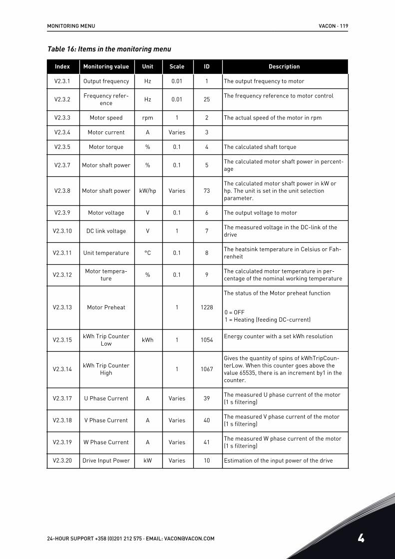
Table 16: Items in the monitoring menu
Index Monitoring value Unit Scale ID Description
V2.3.1 Output frequency Hz 0.01 1 The output frequency to motor
V2.3.2 Frequency refer-ence Hz 0.01 25 The frequency reference to motor control
V2.3.3 Motor speed rpm 1 2 The actual speed of the motor in rpm
V2.3.4 Motor current A Varies 3
V2.3.5 Motor torque % 0.1 4 The calculated shaft torque
V2.3.7 Motor shaft power % 0.1 5 The calculated motor shaft power in percent-age
V2.3.8 Motor shaft power kW/hp Varies 73The calculated motor shaft power in kW orhp. The unit is set in the unit selectionparameter.
V2.3.9 Motor voltage V 0.1 6 The output voltage to motor
V2.3.10 DC link voltage V 1 7 The measured voltage in the DC-link of thedrive
V2.3.11 Unit temperature °C 0.1 8 The heatsink temperature in Celsius or Fah-renheit
V2.3.12 Motor tempera-ture % 0.1 9 The calculated motor temperature in per-
centage of the nominal working temperature
V2.3.13 Motor Preheat 1 1228
The status of the Motor preheat function
0 = OFF1 = Heating (feeding DC-current)
V2.3.15 kWh Trip CounterLow kWh 1 1054 Energy counter with a set kWh resolution
V2.3.14 kWh Trip CounterHigh 1 1067
Gives the quantity of spins of kWhTripCoun-terLow. When this counter goes above thevalue 65535, there is an increment by1 in thecounter.
V2.3.17 U Phase Current A Varies 39 The measured U phase current of the motor(1 s filtering)
V2.3.18 V Phase Current A Varies 40 The measured V phase current of the motor(1 s filtering)
V2.3.19 W Phase Current A Varies 41 The measured W phase current of the motor(1 s filtering)
V2.3.20 Drive Input Power kW Varies 10 Estimation of the input power of the drive
MONITORING MENU VACON · 119
24-HOUR SUPPORT +358 (0)201 212 575 · EMAIL: [email protected] 4

4.1.4 I/O
Table 17: I/O signal monitoring
Index Monitoring value Unit Scale ID Description
V2.4.1 Slot A DIN 1, 2, 3 1 15 Shows the status of the digital inputs 1-3 inslot A (standard I/O)
V2.4.2 Slot A DIN 4, 5, 6 1 16 Shows the status of the digital inputs 4-6 inslot A (standard I/O)
V2.4.3 Slot B RO 1, 2, 3 1 17 Shows the status of the relay inputs 1-3 inslot B
V2.4.4 Analogue input 1 % 0.01 59 The input signal as a percentage of the usedrange. Slot A.1 as default.
V2.4.5 Analogue input 2 % 0.01 60 The input signal as a percentage of the usedrange. Slot A.2 as default.
V2.4.6 Analogue input 3 % 0.01 61 The input signal as a percentage of the usedrange. Slot D.1 as default.
V2.4.7 Analogue input 4 % 0.01 62 The input signal as a percentage of the usedrange. Slot D.2 as default.
V2.4.8 Analogue input 5 % 0.01 75 The input signal as a percentage of the usedrange. Slot E.1 as default.
V2.4.9 Analogue input 6 % 0.01 76 The input signal as a percentage of the usedrange. Slot E.2 as default.
V2.4.10 Slot A AO1 % 0.01 81 The analogue output signal as a percentageof the used range. Slot A (standard I/O)
4.1.5 TEMPERATURE INPUTS
NOTE!
This parameter group is visible when you have an option board for temperaturemeasurement (OPT-BH).
VACON · 120 MONITORING MENU
4 TEL. +358 (0)201 2121 · FAX +358 (0)201 212 205

Table 18: Monitoring the temperature inputs
Index Monitoring value Unit Scale ID Description
V2.5.1 Temperatureinput 1 °C 0.1 50
The measured value of temperature input 1.The list of temperature inputs is made of thefirst 6 available temperature inputs. The liststarts from slot A and ends in slot E. If aninput is available but no sensor is connected,the list shows the maximum value becausethe measured resistance is endless. To makethe value go to its minimum value, hardwirethe input.
V2.5.2 Temperatureinput 2 °C 0.1 51 The measured value of temperature input 2.
See more above.
V2.5.3 Temperatureinput 3 °C 0.1 52 The measured value of temperature input 3.
See more above.
V2.5.4 Temperatureinput 4 °C 0.1 69 The measured value of temperature input 4.
See more above.
V2.5.5 Temperatureinput 5 °C 0.1 70 The measured value of temperature input 5.
See more above.
V2.5.6 Temperatureinput 6 °C 0.1 71 The measured value of temperature input 6.
See more above.
MONITORING MENU VACON · 121
24-HOUR SUPPORT +358 (0)201 212 575 · EMAIL: [email protected] 4

4.1.6 EXTRAS AND ADVANCED
Table 19: Monitoring of the advanced values
Index Monitoring value Unit Scale ID Description
V2.6.1 Drive Status Word 1 43
The bit-coded word
B1 = ReadyB2 = RunB3 = FaultB6 = RunEnableB7 = AlarmActiveB10 = DC current in stopB11 = DC brake activeB12 = RunRequestB13 = MotorRegulatorActive
V2.6.2 Ready Status 1 78
Bit-coded data about the Ready criteria. Usethe data to monitor the processes when thedrive is not in the Ready status.You can see the values as checkboxes on thegraphical display. If a box is ticked, the valueis active.
B0 = RunEnable highB1 = No fault activeB2 = Charge switch closedB3 = DC voltage within limitsB4 = Power manager initialisedB5 = Power unit does not block the startB6 = System software does not block start
V2.6.3 Application StatusWord1 1 89
Bit-coded statuses of the application. You cansee the values as checkboxes on the graphi-cal display. If a box is ticked, the value isactive.
B0 = Interlock 1B1 = Interlock 2B2 = ReservedB3 = Ramp 2 activeB4 = Mechanical brake controlB5 = I/O A control activeB6 = I/O B control activeB7 = Fieldbus Control ActiveB8 = Local control activeB9 = PC control activeB10 = Preset frequencies activeB11 = Flushing activeB12 = Fire Mode activeB13 = Motor Preheat activeB14 = Quick stop activeB15 = Drive stopped from keypad
VACON · 122 MONITORING MENU
4 TEL. +358 (0)201 2121 · FAX +358 (0)201 212 205

Table 19: Monitoring of the advanced values
Index Monitoring value Unit Scale ID Description
V2.6.4 Application StatusWord2 1 90
Bit-coded statuses of the application. You cansee the values as checkboxes on the graphi-cal display. If a box is ticked, the value isactive.
B0 = Acc/Dec prohibitedB1 = Motor switch openB2 = PID activeB3 = PID sleep activeB4 = PID soft fill activeB5 = Autocleaning activeB6 = Jockey pump activeB7 = Priming pump activeB8 = Anti-blocking activeB9 = Input pressure supervision (Alarm/Fault)B10 = Frost protection (Alarm/Fault)B11 = Overpressure alarm
V2.6.5 DIN Status Word 1 1 56
A 16-bit word, where each bit shows the sta-tus of 1 digital input. 6 digital inputs fromeach slot are read. Word 1 starts from theinput 1 in slot A (bit0) and ends with input 4 inslot C (bit15).
V2.6.6 DIN Status Word 2 1 57
A 16-bit word, where each bit shows the sta-tus of 1 digital input. 6 digital inputs fromeach slot are read. Word 2 starts from theinput 5 in slot C (bit0) and ends with input 6 inslot E (bit13).
V2.6.7 Motor Current 1Decimal 0.1 45
The motor current with a specified number ofdecimals and that is less filtered. Use thedata, for example, with fieldbus to get thecorrect value so that the frame size does nothave an effect. Or, to monitor the status whenless filter time is needed for the motor cur-rent.
MONITORING MENU VACON · 123
24-HOUR SUPPORT +358 (0)201 212 575 · EMAIL: [email protected] 4

Table 19: Monitoring of the advanced values
Index Monitoring value Unit Scale ID Description
V2.6.8 Frequency Refer-ence Source 1 1495
Shows the source of the momentary fre-quency reference.
0 = PC1 = Preset Freqs2 = Keypad Reference3 = Fieldbus4 = AI15 = AI26 = AI1+AI27 = PID Controller8 = Motor Potentiom.10 = Flushing100 = Not defined101 = Alarm,PresetFreq102 = Autocleaning
V2.6.9 Last Active FaultCode 1 37 The fault code of the last fault that is not
reset.
V2.6.10 Last Active FaultID 1 95 The fault ID of the last fault that is not reset.
V2.6.11 Last Active AlarmCode 1 74 The alarm code of the last alarm that is not
reset.
V2.6.12 Last Active AlarmID 1 94 The alarm ID of the last alarm that is not
reset.
4.1.7 TIMER FUNCTIONS MONITORINGMonitor the values of Timer functions and the Real Time Clock.
VACON · 124 MONITORING MENU
4 TEL. +358 (0)201 2121 · FAX +358 (0)201 212 205

Table 20: Monitoring of the timer functions
Index Monitoring value Unit Scale ID Description
V2.7.1 TC 1, TC 2, TC 3 1 1441 You can monitor the statuses of the 3 timechannels (TC)
V2.7.2 Interval 1 1 1442 The status of the timer interval
V2.7.3 Interval 2 1 1443 The status of the timer interval
V2.7.4 Interval 3 1 1444 The status of the timer interval
V2.7.5 Interval 4 1 1445 The status of the timer interval
V2.7.6 Interval 5 1 1446 The status of the timer interval
V2.7.7 Timer 1 s 1 1447 The remaining time on the timer if the timeris active
V2.7.8 Timer 2 s 1 1448 The remaining time on the timer if the timeris active
V2.7.9 Timer 3 s 1 1449 The remaining time on the timer if the timeris active
V2.7.10 Real time clock 1450 hh:mm:ss
MONITORING MENU VACON · 125
24-HOUR SUPPORT +358 (0)201 212 575 · EMAIL: [email protected] 4

4.1.8 PID CONTROLLER MONITORING
Table 21: Monitoring of the values of the PID controller
Index Monitoring value Unit Scale ID Description
V2.8.1 PID1 Setpoint VariesAs is set
inP3.13.1.7
20The setpoint value of the PID controller inprocess units. You can use a parameter tomake the selection of the process unit.
V2.8.2 PID1 Feedback VariesAs is set
inP3.13.1.7
21The feedback value of the PID controller inprocess units. You can use a parameter tomake the selection of the process unit.
V2.8.3 PID Feedback(Source 1)
Varies As is setin
P3.13.1.715541
The feedback value of the PID controller(from source 1 of the feedback signal)
V2.8.4 PID Feedback(Source 2)
Varies As is setin
P3.13.1.715542
The feedback value of the PID controller(from source 2 of the feedback signal)
V2.8.5 PID1 Error Value VariesAs is set
inP3.13.1.7
22
The error value of the PID controller. It is thedeviation of feedback from the setpoint inprocess units. You can use a parameter tomake the selection of the process unit.
V2.8.6 PID1 Output % 0.01 23
The PID output as a percentage (0..100%). Itis possible to give this value to the motorcontrol (frequency reference) or to an ana-logue output.
V2.8.7 PID1 Status 1 24
0 = Stopped1 = Running3 = Sleep mode4 = In dead band (see 5.13 Group 3.13: PID controller 1)
VACON · 126 MONITORING MENU
4 TEL. +358 (0)201 2121 · FAX +358 (0)201 212 205

4.1.9 EXTERNAL PID CONTROLLER MONITORING
Table 22: Monitoring of the values of the external PID controller
Index Monitoring value Unit Scale ID Description
V2.9.1 ExtPID setpoint Varies
As set inP3.14.1.1
0 (See5.14
Group 3.14:
External PID con-troller)
83
The setpoint value of the external PID con-troller in process units. You can use aparameter to make the selection of the proc-ess unit.
V2.9.2 ExtPID feedback VariesAs set inP3.14.1.1
084
The feedback value of the external PID con-troller in process units. You can use aparameter to make the selection of the proc-ess unit.
V2.9.3 ExtPID error value VariesAs set inP3.14.1.1
085
The error value of the external PID control-ler. It is the deviation of feedback from thesetpoint in process units. You can use aparameter to make the selection of the proc-ess unit.
V2.9.4 ExtPID output % 0.01 86The external PID controller output as a per-centage (0..100%). It is possible to give thisvalue to, for example, the analogue output.
V2.9.5 ExtPID status 1 870=Stopped1=Running2=In dead band (see 5.14 Group 3.14: External PID controller)
4.1.10 MULTIPUMP MONITORINGYou can use the monitoring values from Pump 2 Running Time to Pump 8 Running Time inthe Multipump (single drive) mode.
If you use Multimaster or Multifollower mode, read the value of the pump runtime counterfrom the monitoring value Pump (1) Running Time. Read the pump runtime from each drive.
MONITORING MENU VACON · 127
24-HOUR SUPPORT +358 (0)201 212 575 · EMAIL: [email protected] 4

Table 23: Multipump monitoring
Index Monitoring value Unit Scale ID Description
V2.10.1 Motors running 1 30 The number of motors that operate when theMultipump function is used.
V2.10.2 Autochange 1 1113 The status of the autochange request
V2.10.3 Next Autochange h 0.1 1503 The time to the next autochange
V2.10.4 Operate Mode 1 1505
Operation mode of the drive in the Multipumpsystem.
0 = Slave1 = Master
V2.10.5 Multipump Status 1 1628
0 = Not used10 = Stopped20 = Sleep30 = Anti-blocking40 = Auto-cleaning50 = Flushing60 = Soft filling70 = Regulating80 = Following90 = Const. producing200 = Unknown
V2.10.6 CommunicationStatus h 0.1 1629
0 = Not used (Multipump multidrive function)10 = Fatal communication errors occurred(or no communication)11 = Errors occurred (data sending)12 = Errors occurred (data receiving)20 = Communication operational, no errorsoccurred30 = Status unknown
V2.10.7 Pump (1) RunningTime h 0.1 1620
Single drive mode: operating hours of pump 1Multidrive mode: operating hours of thisdrive (this pump)
V2.10.8 Pump (2) RunningTime h 0.1 1621 Single drive mode: operating hours of pump 2
Multidrive mode: Not used
V2.10.9 Pump (3) RunningTime h 0.1 1622 Single drive mode: operating hours of pump 3
Multidrive mode: Not used
V2.10.10 Pump (4) RunningTime h 0.1 1623 Single drive mode: operating hours of pump 4
Multidrive mode: Not used
V2.10.11 Pump (5) RunningTime h 0.1 1624 Single drive mode: operating hours of pump 5
Multidrive mode: Not used
VACON · 128 MONITORING MENU
4 TEL. +358 (0)201 2121 · FAX +358 (0)201 212 205

Table 23: Multipump monitoring
Index Monitoring value Unit Scale ID Description
V2.10.12 Pump (6) RunningTime h 0.1 1625 Single drive mode: operating hours of pump 6
Multidrive mode: Not used
V2.10.13 Pump (7) RunningTime h 0.1 1626 Single drive mode: operating hours of pump 7
Multidrive mode: Not used
V2.10.14 Pump (8) RunningTime h 0.1 1627 Single drive mode: operating hours of pump 8
Multidrive mode: Not used
4.1.11 MAINTENANCE COUNTERS
Table 24: Maintenance counter monitoring
Index Monitoring value Unit Scale ID Description
V2.11.1 Maintenancecounter 1 h/ kRev Varies 1101
The status of the maintenance counter asrevolutions multiplied by 1000, or in hours.For the configuration and activation of thiscounter, see 5.16 Group 3.16: Maintenance counters.
MONITORING MENU VACON · 129
24-HOUR SUPPORT +358 (0)201 212 575 · EMAIL: [email protected] 4

4.1.12 FIELDBUS PROCESS DATA MONITORING
Table 25: Fieldbus process data monitoring
Index Monitoring value Unit Scale ID Description
V2.12.1 FB Control Word 1 874
The fieldbus control word that the applicationuses in bypass mode/format. Depending onthe fieldbus type or profile, the data can bemodified before it is sent to the application.
V2.12.2 FB Speed Refer-ence Varies 875
The speed reference scaled between theminimum and the maximum frequency at themoment when the application received it. Youcan change the minimum and the maximumfrequencies after the application received thereference without an effect on the reference.
V2.12.3 FB data in 1 1 876 The raw value of process data in a 32-bitsigned format
V2.12.4 FB data in 2 1 877 The raw value of process data in a 32-bitsigned format
V2.12.5 FB data in 3 1 878 The raw value of process data in a 32-bitsigned format
V2.12.6 FB data in 4 1 879 The raw value of process data in a 32-bitsigned format
V2.12.7 FB data in 5 1 880 The raw value of process data in a 32-bitsigned format
V2.12.8 FB data in 6 1 881 The raw value of process data in a 32-bitsigned format
V2.12.9 FB data in 7 1 882 The raw value of process data in a 32-bitsigned format
V2.12.10 FB data in 8 1 883 The raw value of process data in a 32-bitsigned format
V2.12.11 FB Status Word 1 864
The fieldbus status word that the applicationsends in bypass mode/format. Depending onthe fieldbus type or profile, the data can bemodified before it is sent to the fieldbus.
V2.12.12 FB Speed Actual 0.01 865
The actual speed as a percentage. The value0% agrees with the minimum frequency andthe value 100% agrees with the maximumfrequency. This is continuously updateddepending on the momentary min and maxfrequencies and the output frequency.
V2.12.13 FB data out 1 1 866 The raw value of process data in a 32-bitsigned format
V2.12.14 FB data out 2 1 867 The raw value of process data in a 32-bitsigned format
VACON · 130 MONITORING MENU
4 TEL. +358 (0)201 2121 · FAX +358 (0)201 212 205

Table 25: Fieldbus process data monitoring
Index Monitoring value Unit Scale ID Description
V2.12.15 FB data out 3 1 868 The raw value of process data in a 32-bitsigned format
V2.12.16 FB data out 4 1 869 The raw value of process data in a 32-bitsigned format
V2.12.17 FB data out 5 1 870 The raw value of process data in a 32-bitsigned format
V2.12.18 FB data out 6 1 871 The raw value of process data in a 32-bitsigned format
V2.12.19 FB data out 7 1 872 The raw value of process data in a 32-bitsigned format
V2.12.20 FB data out 8 1 873 The raw value of process data in a 32-bitsigned format
MONITORING MENU VACON · 131
24-HOUR SUPPORT +358 (0)201 212 575 · EMAIL: [email protected] 4

5 PARAMETERS MENUYou can change and edit the parameters in the Parameters menu (M3) at all times.
5.1 GROUP 3.1: MOTOR SETTINGS
Table 26: Motor nameplate parameters
Index Parameter Min Max Unit Default ID Description
P3.1.1.1 Motor Nominal Volt-age Varies Varies V Varies 110
Find the value Un onthe rating plate of themotor.
Find out if the motorconnection is Delta orStar.
P3.1.1.2Motor Nominal Fre-
quency 8.00 320.00 Hz 50 / 60 111
Find the value fn on therating plate of themotor.
P3.1.1.3 Motor NominalSpeed 24 19200 rpm Varies 112
Find the value nn onthe rating plate of themotor.
P3.1.1.4 Motor Nominal Cur-rent IH * 0.1 IH * 2 A Varies 113
Find the value In on therating plate of themotor.
P3.1.1.5 Motor Cos Phi(Power Factor) 0.30 1.00 Varies 120
Find the value on therating plate of themotor.
P3.1.1.6 Motor NominalPower Varies Varies kW Varies 116
Find the value In on therating plate of themotor.
VACON · 132 PARAMETERS MENU
5 TEL. +358 (0)201 2121 · FAX +358 (0)201 212 205

Table 27: Motor control settings
Index Parameter Min Max Unit Default ID Description
P3.1.2.2
Motor Type 0 1 0 650 0 = Induction motor1 = PM motor
P3.1.2.3 Switching Frequency 1.5 Varies kHz Varies 601
If you increase theswitching frequency,the capacity of the ACdrive decreases. Todecrease capacitivecurrents in the motorcable, when the cableis long, use a lowswitching frequency.To decrease the motornoise, use a highswitching frequency.
P3.1.2.4
Identification 0 2 0 631
Identification calcu-lates or measures themotor parameters thatare necessary for agood control of themotor and speed.
0 = No action1 = At standstill2 = With rotation
Before you do the iden-tification run, you mustset the motor name-plate parameters in themenu M3.1.1.
P3.1.2.5 Magnetising Current 0.0 2*IH A 0.0 612
The magnetising cur-rent (no-load current)of the motor. The mag-netising current identi-fies the values of theU/f parameters, if yougive them before theidentification run. If youset the value to 0, themagnetising current iscalculated internally.
PARAMETERS MENU VACON · 133
24-HOUR SUPPORT +358 (0)201 212 575 · EMAIL: [email protected] 5

Table 27: Motor control settings
Index Parameter Min Max Unit Default ID Description
P3.1.2.6
Motor Switch 0 1 0 653
When you enable thisfunction, the drive doesnot trip when themotor switch is closedand opened, for exam-ple in a flying start.
0 = Disabled1 = Enabled
P3.1.2.10
Overvoltage Control 0 1 1 607 0 = Disabled1 = Enabled
P3.1.2.11
Undervoltage Control 0 1 1 608 0 = Disabled1 = Enabled
P3.1.2.12 Energy Optimisation 0 1 0 666
To use less energy andto lower the motornoise, the drive findsthe minimum motorcurrent. You can usethis function for exam-ple in fan and pumpprocesses. Do not usethe function with fastPID-controlled pro-cesses.
0 = Disabled1 = Enabled
P3.1.2.13
Stator Voltage Adjust 50.0 150.0 % 100.0 659
Use this to adjust thestator voltage in per-manent magnetmotors.
VACON · 134 PARAMETERS MENU
5 TEL. +358 (0)201 2121 · FAX +358 (0)201 212 205

Table 28: Motor limit settings
Index Parameter Min Max Unit Default ID Description
P3.1.3.1
Motor Current Limit IH*0.1 IS A Varies 107
The maximum motorcurrent from the ACdrive
P3.1.3.2 Motor Torque Limit 0.0 300.0 % 300.0 1287The maximum torquelimit of the motoringside
PARAMETERS MENU VACON · 135
24-HOUR SUPPORT +358 (0)201 212 575 · EMAIL: [email protected] 5

Table 29: Open loop settings
Index Parameter Min Max Unit Default ID Description
P3.1.4.1
U/f Ratio 0 2 0 108
The type of the U/fcurve between 0 fre-quency and the fieldweakening point.
0=Linear1=Squared2=Programmable
P3.1.4.2 Field WeakeningPoint Frequency 8.00 P3.3.1.2 Hz Varies 602
The field weakeningpoint is the output fre-quency at which theoutput voltage gets tothe field weakeningpoint voltage.
P3.1.4.3Voltage at Field
Weakening Point 10.00 200.00 % 100.00 603
The voltage at the fieldweakening point as apercentage of themotor nominal voltage.
P3.1.4.4 U/f Midpoint Fre-quency 0.00 P3.1.4.2. Hz Varies 604
If the value of P3.1.4.1is programmable, thisparameter gives themiddle point frequencyof the curve.
P3.1.4.5 U/f Midpoint Voltage 0.0 100.0 % 100.0 605
If the value of P3.1.4.1is programmable, thisparameter gives themiddle point voltage ofthe curve.
P3.1.4.6 Zero Frequency Volt-age 0.00 40.00 % Varies 606
This parameter givesthe 0 frequency voltageof the U/f curve. Thedefault value is differ-ent for different unitsizes.
VACON · 136 PARAMETERS MENU
5 TEL. +358 (0)201 2121 · FAX +358 (0)201 212 205

Table 29: Open loop settings
Index Parameter Min Max Unit Default ID Description
P3.1.4.7
Flying Start Options 0 51 0 1590
A checkbox selec-tionB0 = Search the shaftfrequency only fromthe same direction asthe frequency refer-enceB1 = Disable AC scan-ningB4 = Use the frequencyreference for the initialguessB5 = Disable DC pulses
P3.1.4.8 Flying Start ScanCurrent 0.0 100.0 % 45.0 1610 As a percentage of the
motor nominal current.
P3.1.4.9
Start Boost 0 1 0 109 0=Disabled1=Enabled
M3.1.4.12 I/f Start This menu includes 3 parameters. See the table below.
Table 30: I/f start parameters
Index Parameter Min Max Unit Default ID Description
P3.1.4.12.1
I/f Start 0 1 0 534 0 = Disabled1 = Enabled
P3.1.4.12.2
I/f Start Frequency 5.0 0.5 *P3.1.1.2
0.2 *P3.1.1.2 535
The output frequencylimit below which theset I/f start current isfed to motor.
P3.1.4.12.3
I/f Start Current 0.0 100.0 % 80.0 536
The current that is fedto the motor when theI/f Start function isactivated.
PARAMETERS MENU VACON · 137
24-HOUR SUPPORT +358 (0)201 212 575 · EMAIL: [email protected] 5

5.2 GROUP 3.2: START/STOP SETUP
Table 31: Start/stop setup menu
Index Parameter Min Max Unit Default ID Description
P3.2.1 Remote ControlPlace 0 1 0 * 172
The selection of theremote control place(start/stop). Use this tochange back to remotecontrol from VaconLive, for example if thecontrol panel is bro-ken.
0 = I/O control1 = Fieldbus control
P3.2.2 Local/Remote 0 1 0 * 211
Switch between thelocal and remote con-trol places.
0 = Remote1 = Local
P3.2.3 Keypad Stop Button 0 1 0 1140 = The Stop buttonalways enabled (Yes)1 = Limited function ofthe Stop button (No)
P3.2.4 Start Function 0 1 0 505 0 = Ramping1 = Flying start
P3.2.5
Stop Function 0 1 0 506 0 = Coasting1 = Ramping
VACON · 138 PARAMETERS MENU
5 TEL. +358 (0)201 2121 · FAX +358 (0)201 212 205

Table 31: Start/stop setup menu
Index Parameter Min Max Unit Default ID Description
P3.2.6I/O A Start/Stop
Logic 0 4 2 * 300
Logic = 0Ctrl sgn 1 = ForwardCtrl sgn 2 = Backward
Logic = 1Ctrl sgn 1 = Forward(edge)Ctrl sgn 2 = InvertedStopCtrl sgn 3 = Bckwrd(edge)
Logic = 2Ctrl sgn 1 = Forward(edge)Ctrl sgn 2 = Bckwrd(edge)
Logic = 3Ctrl sgn 1 = StartCtrl sgn 2 = Reverse
Logic = 4Ctrl sgn 1 = Start(edge)Ctrl sgn 2 = Reverse
P3.2.7 I/O B Start/StopLogic 0 4 2 * 363 See above.
P3.2.8 Fieldbus Start Logic 0 1 0 889 0 = A rising edge isnecessary1 = State
P3.2.9 Start Delay 0.000 60.000 s 0.000 524
The delay between thestart command and theactual start of thedrive.
PARAMETERS MENU VACON · 139
24-HOUR SUPPORT +358 (0)201 212 575 · EMAIL: [email protected] 5

Table 31: Start/stop setup menu
Index Parameter Min Max Unit Default ID Description
P3.2.10 Remote to LocalFunction 0 2 2 181
The selection of copysettings when you gofrom Remote to Local(keypad) control.
0 = Keep Run1 = Keep Run & Refer-ence2 = Stop
P3.2.11 Restart Delay 0.0 20.0 min 0.0 15555
The delay time duringwhich the drive cannotbe restarted.
0 = Not used
* = The selection of the application with parameter P1.2 Application gives the default value.See the default values in Chapter 12.1 The default values of parameters in the different applications.
VACON · 140 PARAMETERS MENU
5 TEL. +358 (0)201 2121 · FAX +358 (0)201 212 205

5.3 GROUP 3.3: REFERENCES
Table 32: Frequency reference parameters
Index Parameter Min Max Unit Default ID Description
P3.3.1.1 Minimum FrequencyReference 0.00 P3.3.1.2 Hz 0.00 101 The minimum fre-
quency reference
P3.3.1.2 Maximum FrequencyReference P3.3.1.1 320.00 Hz 50.00 /
60.00 102 The maximum fre-quency reference
P3.3.1.3 Positive FrequencyReference Limit -320.0 320.0 Hz 320.00 1285
The final frequency ref-erence limit for thepositive direction.
P3.3.1.4 Negative FrequencyReference Limit -320.0 320.0 Hz -320.00 1286
The final frequency ref-erence limit for thenegative direction. Usethis parameter, forexample, to prevent themotor from running inthe reverse direction.
P3.3.1.5 I/O Control Refer-ence A Selection 0 20 6 * 117
Selection of the refer-ence source when thecontrol place is I/O A.
0 = PC1 = Preset frequency 02 = Keypad reference3 = Fieldbus4 = AI15 = AI26 = AI1+AI27 = PID8 = Motor potentiome-ter11 = Block Out.112 = Block Out.213 = Block Out.314 = Block Out.415 = Block Out.516 = Block Out.617 = Block Out.718 = Block Out.819 = Block Out.920 = Block Out.10
P3.3.1.6 I/O Control Refer-ence B Selection 0 20 4 * 131
Selection of the refer-ence source when thecontrol place is I/O B.See above. You canmake the I/O B controlplace active only with adigital input (P3.5.1.7).
PARAMETERS MENU VACON · 141
24-HOUR SUPPORT +358 (0)201 212 575 · EMAIL: [email protected] 5

Table 32: Frequency reference parameters
Index Parameter Min Max Unit Default ID Description
P3.3.1.7 Keypad Control Ref-erence Selection 0 20 1 * 121
Selection of the refer-ence source when thecontrol place is keypad.
0 = PC1 = Preset frequency 02 = Keypad reference3 = Fieldbus4 = AI15 = AI26 = AI1+AI27 = PID8 = Motor potentiome-ter11 = Block Out.112 = Block Out.213 = Block Out.314 = Block Out.415 = Block Out.516 = Block Out.617 = Block Out.718 = Block Out.819 = Block Out.920 = Block Out.10
P3.3.1.8 Keypad Reference 0.00 P3.3.1.2. Hz 0.00 184
You can adjust the fre-quency reference onthe keypad with thisparameter.
P3.3.1.9 Keypad Direction 0 1 0 123
The rotation directionof the motor when thecontrol place is keypad.
0 = Forward1 = Reverse
VACON · 142 PARAMETERS MENU
5 TEL. +358 (0)201 2121 · FAX +358 (0)201 212 205

Table 32: Frequency reference parameters
Index Parameter Min Max Unit Default ID Description
P3.3.1.10 Fieldbus ControlReference Selection 0 20 2 * 122
Selection of the refer-ence source when thecontrol place is Field-bus.
0 = PC1 = Preset frequency 02 = Keypad reference3 = Fieldbus4 = AI15 = AI26 = AI1+AI27 = PID8 = Motor potentiome-ter11 = Block Out.112 = Block Out.213 = Block Out.314 = Block Out.415 = Block Out.516 = Block Out.617 = Block Out.718 = Block Out.819 = Block Out.920 = Block Out.10
* = The selection of the application with parameter P1.2 Application gives the default value.See the default values in Chapter 12.1 The default values of parameters in the different applications.
PARAMETERS MENU VACON · 143
24-HOUR SUPPORT +358 (0)201 212 575 · EMAIL: [email protected] 5

Table 33: Preset frequency parameters
Index Parameter Min Max Unit Default ID Description
P3.3.3.1Preset Frequency
Mode 0 1 0 * 182
0 = Binary coded1 = Number of inputs
The preset frequency isspecified by the num-ber preset speed digi-tal inputs that areactive.
P3.3.3.2
Preset Frequency 0 P3.3.1.1 P3.3.1.2 Hz 5.00 180
The basic preset fre-quency 0 when youselect it with P3.3.1.5.
P3.3.3.3
Preset Frequency 1 P3.3.1.1 P3.3.1.2 Hz 10.00 * 105
Make the selectionwith digital input Pre-set frequency selection0 (P3.3.3.10).
P3.3.3.4
Preset Frequency 2 P3.3.1.1 P3.3.1.2 Hz 15.00 * 106
Make the selectionwith digital input Pre-set frequency selection1 (P3.3.3.11).
P3.3.3.5
Preset Frequency 3 P3.3.1.1 P3.3.1.2 Hz 20.00 * 126
Make the selectionwith digital inputs Pre-set frequency selection0 & 1.
P3.3.3.6
Preset Frequency 4 P3.3.1.1 P3.3.1.2 Hz 25.00 * 127
Make the selectionwith digital input Pre-set frequency selection2 (P3.3.3.12).
P3.3.3.7
Preset Frequency 5 P3.3.1.1 P3.3.1.2 Hz 30.00 * 128
Make the selectionwith digital inputs Pre-set frequency selection0 & 2.
P3.3.3.8
Preset Frequency 6 P3.3.1.1 P3.3.1.2 Hz 40.00 * 129
Make the selectionwith digital inputs Pre-set frequency selection1 & 2.
P3.3.3.9
Preset Frequency 7 P3.3.1.1 P3.3.1.2 Hz 50.00 * 130
Make the selectionwith digital inputs Pre-set frequency selection0 & 1 & 2.
P3.3.3.10Preset Frequency
Selection 0DigIN
SlotA.4 419
A binary selector forPreset speeds (0-7).See parametersP3.3.3.2 to P3.3.3.9.
VACON · 144 PARAMETERS MENU
5 TEL. +358 (0)201 2121 · FAX +358 (0)201 212 205

Table 33: Preset frequency parameters
Index Parameter Min Max Unit Default ID Description
P3.3.3.11Preset Frequency
Selection 1DigIN
SlotA.5 420
A binary selector forPreset speeds (0-7).See parametersP3.3.3.2 to P3.3.3.9.
P3.3.3.12Preset Frequency
Selection 2DigIN
Slot0.1 421
A binary selector forPreset speeds (0-7).See parametersP3.3.3.2 to P3.3.3.9.
* The default value of the parameter is specified by the application that you select withparameter P1.2 Application. See 10.1 Default parameter values.
Table 34: Motor potentiometer parameters
Index Parameter Min Max Unit Default ID Description
P3.3.4.1Motor Potentiometer
UPDigIN
Slot0.1 418
OPEN = Not activeCLOSED = Active. Themotor potentiometerreference INCREASESuntil the contactopens.
P3.3.4.2Motor Potentiometer
DOWNDigIN
Slot0.1 417
OPEN = Not activeCLOSED = Active. Themotor potentiometerreference DECREASESuntil the contact isopened.
P3.3.4.3 Motor PotentiometerRamp Time 0.1 500.0 Hz/s 10.0 331
The rate of change inthe motor potentiome-ter reference when it isincreased or decreasedwith P3.3.4.1. orP3.3.4.2.
P3.3.4.4Motor Potentiometer
Reset 0 2 1 367
The reset logic for themotor potentiometerfrequency reference.
0 = No reset1 = Reset if stopped2 = Reset if powereddown
PARAMETERS MENU VACON · 145
24-HOUR SUPPORT +358 (0)201 212 575 · EMAIL: [email protected] 5

Table 35: Flushing parameters
Index Parameter Min Max Unit Default ID Description
P3.3.6.1 Activate FlushingReference
DigINSlot0.1 * 530
Connect to the digitalinput to activateparameter P3.3.6.2.The drive starts if theinput is activated.
P3.3.6.2 Flushing reference -MaxRef MaxRef Hz 0.00 * 1239
Gives the frequencyreference when theflushing reference isactivated (P3.3.6.1).
* The default value of the parameter is specified by the application that you select withparameter P1.2 Application. See 10.1 Default parameter values.
5.4 GROUP 3.4: RAMPS AND BRAKES SETUP
Table 36: Ramp 1 setup
Index Parameter Min Max Unit Default ID Description
P3.4.1.1
Ramp 1 Shape 0.0 100.0 % 0.0 500
You can makesmoother the start andthe end of the acceler-ation and decelerationramps.
P3.4.1.2
Acceleration Time 1 0.1 300.0 s 5.0 103
Gives the time that isnecessary for the out-put frequency toincrease from zero fre-quency to maximumfrequency.
P3.4.1.3
Deceleration Time 1 0.1 300.0 s 5.0 104
Gives the time that isnecessary for the out-put frequency todecrease from maxi-mum frequency to zerofrequency.
VACON · 146 PARAMETERS MENU
5 TEL. +358 (0)201 2121 · FAX +358 (0)201 212 205

Table 37: Ramp 2 setup
Index Parameter Min Max Unit Default ID Description
P3.4.2.1
Ramp 2 Shape 0.0 100.0 % 0.0 501
You can makesmoother the start andthe end of the acceler-ation and decelerationramps.
P3.4.2.2 Acceleration Time 2 0.1 300.0 s 10.0 502
Gives the time that isnecessary for the out-put frequency toincrease from zero fre-quency to maximumfrequency.
P3.4.2.3 Deceleration Time 2 0.1 300.0 s 10.0 503
Gives the time that isnecessary for the out-put frequency todecrease from maxi-mum frequency to zerofrequency.
P3.4.2.4 Ramp 2 Selection Varies Varies DigINSlot0.1 408
The selection of theramp 1 or 2.
OPEN = Ramp 1 Shape,Acceleration Time 1and Deceleration Time1.CLOSED = Ramp 2Shape, AccelerationTime 2 and Decelera-tion Time 2.
P3.4.2.5 Ramp 2 ThresholdFrequency 0.0 P3.3.1.2 Hz 0.0 533
Gives the frequency,above which the sec-ond ramp times andshapes are used.
0 = Not used
PARAMETERS MENU VACON · 147
24-HOUR SUPPORT +358 (0)201 212 575 · EMAIL: [email protected] 5

Table 38: Start magnetisation parameters
Index Parameter Min Max Unit Default ID Description
P3.4.3.1 Start MagnetisingCurrent 0.00 IL A IH 517
Gives the DC currentthat is fed into themotor at the start.
0 = Disabled
P3.4.3.2 Start MagnetisingTime 0.00 600.00 s 0.00 516
Gives the time duringwhich the DC current isfed to the motor beforethe acceleration starts.
Table 39: DC brake parameters
Index Parameter Min Max Unit Default ID Description
P3.4.4.1 DC Brake Current 0 IL A IH 507
Gives the current thatis fed into the motorduring DC braking.
0 = Disabled
P3.4.4.2 DC Braking Time atStop 0.00 600.00 s 0.00 508
Gives the braking timewhen the motor stops.
0 = DC braking notused
P3.4.4.3Frequency to Start
DC Braking at RampStop
0.10 10.00 Hz 1.50 515The output frequencyat which the DC brak-ing starts.
Table 40: Flux braking parameters
Index Parameter Min Max Unit Default ID Description
P3.4.5.1
Flux Braking 0 1 0 520 0 = Disabled1 = Enabled
P3.4.5.2 Flux Braking Current 0 IL A IH 519 Gives the current levelfor the flux braking.
VACON · 148 PARAMETERS MENU
5 TEL. +358 (0)201 2121 · FAX +358 (0)201 212 205

5.5 GROUP 3.5: I/O CONFIGURATION
Table 41: Digital input settings
Index Parameter Default ID Description
P3.5.1.1 Control Signal 1 A DigIN SlotA.1 * 403 Ctrl signal 1 when the control place isI/O A (FWD).
P3.5.1.2 Control Signal 2 A DigIN SlotA.2 * 404 Ctrl signal 2 when the control place isI/O A (REV).
P3.5.1.3 Control Signal 3 A DigIN Slot0.1 434 Ctrl signal 3 when the control place isI/O A.
P3.5.1.4 Control Signal 1 B DigIN Slot0.1 * 423 Start signal 1 when the control placeis I/O B.
P3.5.1.5 Control Signal 2 B DigIN Slot0.1 424 Start signal 2 when the control placeis I/O B.
P3.5.1.6 Control Signal 3 B DigIN Slot0.1 435 Start signal 3 when the control placeis I/O B.
P3.5.1.7 I/O B Control Force DigIN Slot0.1 * 425 CLOSED = Force the control place toI/O B.
P3.5.1.8 I/O B Reference Force DigIN Slot0.1 * 343 CLOSED = I/O reference B (P3.3.1.6)gives the frequency reference.
P3.5.1.9 Fieldbus Control Force DigIN Slot0.1 * 411 Force the control to fieldbus.
P3.5.1.10 Keypad Control Force DigIN Slot0.1 * 410 Force the control to keypad.
P3.5.1.11 External Fault Close DigIN SlotA.3 * 405 OPEN = OKCLOSED = External fault
P3.5.1.12 External Fault Open DigIN Slot0.2 406 OPEN = External faultCLOSED = OK
P3.5.1.13 Fault Reset Close DigIN SlotA.6 * 414 CLOSED = Resets all active faults.
P3.5.1.14 Fault Reset Open DigIN Slot0.1 213 OPEN = Resets all active faults.
P3.5.1.15 Run Enable DigIN Slot0.2 407 You can set the drive in Ready state,when this is ON.
P3.5.1.16
Run Interlock 1 DigIN Slot0.2 1041
The drive can be in the Ready state,but the start is not possible when theinterlock is on (Damper interlock).
OPEN = Start not permittedCLOSED = Start permitted
PARAMETERS MENU VACON · 149
24-HOUR SUPPORT +358 (0)201 212 575 · EMAIL: [email protected] 5

Table 41: Digital input settings
Index Parameter Default ID Description
P3.5.1.17
Run Interlock 2 DigIN Slot0.2 1042
As above.
P3.5.1.18 Motor Preheat ON DigIN Slot0.1 1044OPEN = No action.CLOSED = Uses the DC current of themotor preheat in the Stop state. Usedwhen the value of P3.18.1 is 2.
P3.5.1.19 Ramp 2 Selection DigIN Slot0.1 408
Switch between ramps 1 and 2.
OPEN = Ramp 1 Shape, AccelerationTime 1 and Deceleration Time 1.CLOSED = Ramp 2 Shape, Accelera-tion Time 2 and Deceleration Time 2.
P3.5.1.20 Acc/Dec Prohibit DigIN Slot0.1 415 No acceleration or deceleration ispossible until the contact is open.
P3.5.1.21 Preset Frequency Selection 0 DigIN SlotA.4 * 419A binary selector for preset speeds(0-7). See Table 33 Preset frequency parameters.
P3.5.1.22 Preset Frequency Selection 1 DigIN SlotA.5 * 420A binary selector for preset speeds(0-7). See Table 33 Preset frequency parameters.
P3.5.1.23 Preset Frequency Selection 2 DigIN Slot0.1 * 421A binary selector for preset speeds(0-7). See Table 33 Preset frequency parameters.
P3.5.1.24 Motor Potentiometer UP DigIN Slot0.1 418OPEN = Not activeCLOSED = Active. The motor potenti-ometer reference INCREASES untilthe contact is open.
P3.5.1.25 Motor Potentiometer DOWN DigIN Slot0.1 417OPEN = Not activeCLOSED = Active. The motor potenti-ometer reference DECREASES untilthe contact is open.
P3.5.1.26 Quick Stop Activation DigIN Slot0.2 1213OPEN = Activated
To configure these functions, seeTable 58 Quick stop settings.
P3.5.1.27 Timer 1 DigIN Slot0.1 447 The rising edge starts Timer 1 thatwas programmed in Group 3.12.
VACON · 150 PARAMETERS MENU
5 TEL. +358 (0)201 2121 · FAX +358 (0)201 212 205

Table 41: Digital input settings
Index Parameter Default ID Description
P3.5.1.28 Timer 2 DigIN Slot0.1 448 See above.
P3.5.1.29 Timer 3 DigIN Slot0.1 449 See above.
P3.5.1.30 PID1 Setpoint Boost DigIN Slot0.1 1046 OPEN = No boostCLOSED = Boost
P3.5.1.31 PID1 Select Setpoint DigIN Slot0.1 * 1047 OPEN = Setpoint 1CLOSED = Setpoint 2
P3.5.1.32 External PID Start Signal DigIN Slot0.2 1049
OPEN = PID2 in stop modeCLOSED = PID2 regulating
This parameter has no effect if theexternal PID controller is not enabledin Group 3.14.
P3.5.1.33 External PID Select Setpoint DigIN Slot0.1 1048 OPEN = Setpoint 1CLOSED = Setpoint 2
P3.5.1.34 Reset Maintenance Counter 1 DigIN Slot0.1 490 CLOSED = Reset
P3.5.1.36 Flushing Reference Activation DigIN Slot0.1 * 530
Connect to a digital input to activateP3.3.6.2.
NOTE!If the input is activated, the drivestarts.
P3.5.1.38 Fire Mode Activation OPEN DigIN Slot0.2 1596
Activates the Fire mode if it is ena-bled with a correct password.
OPEN = Fire mode activeCLOSED = No action
P3.5.1.39 Fire Mode Activation CLOSE DigIN Slot0.1 1619
Activates the Fire mode if it is ena-bled with a correct password.
OPEN = No actionCLOSED = Fire Mode active
PARAMETERS MENU VACON · 151
24-HOUR SUPPORT +358 (0)201 212 575 · EMAIL: [email protected] 5

Table 41: Digital input settings
Index Parameter Default ID Description
P3.5.1.40 Fire Mode Reverse DigIN Slot0.1 1618
Gives a command of reverse rotationdirection during the Fire mode. Thisfunction has no effect in the normaloperation.
OPEN = ForwardCLOSED = Reverse
P3.5.1.41 Auto-cleaning Activation DigIN Slot0.1 1715
Start the Auto-cleaning. The processstops if the activation signal isremoved before the process is com-plete.
NOTE!If the input is activated, the drivestarts.
P3.5.1.42 Pump 1 Interlock DigIN Slot0.1 * 426 OPEN = Not activeCLOSED = Active
P3.5.1.43 Pump 2 Interlock DigIN Slot0.1 * 427 OPEN = Not activeCLOSED = Active
P3.5.1.44 Pump 3 Interlock DigIN Slot0.1 * 428 OPEN = Not activeCLOSED = Active
P3.5.1.45 Pump 4 Interlock DigIN Slot0.1 429 OPEN = Not activeCLOSED = Active
P3.5.1.46 Pump 5 Interlock DigIN Slot0.1 430 OPEN = Not activeCLOSED = Active
P3.5.1.47 Pump 6 Interlock DigIN Slot0.1 486 OPEN = Not activeCLOSED = Active
P3.5.1.48 Pump 7 Interlock DigIN Slot0.1 487 OPEN = Not activeCLOSED = Active
P3.5.1.49 Pump 8 Interlock DigIN Slot0.1 488 OPEN = Not activeCLOSED = Active
VACON · 152 PARAMETERS MENU
5 TEL. +358 (0)201 2121 · FAX +358 (0)201 212 205

Table 41: Digital input settings
Index Parameter Default ID Description
P3.5.1.52 Reset kWh Trip Counter DigIN Slot0.1 1053 Resets the kWh trip counter
P3.5.1.53 Parameter Set 1/2 Selection DigIN Slot0.1 496
The selection of the digital input sig-nal for the parameter set:
OPEN = Parameter Set 1CLOSED = Parameter Set 2
* = The selection of the application with parameter P1.2 Application gives the default value.See the default values in 12.1 The default values of parameters in the different applications.
NOTE!
Your option board and board setup gives the number of available analogue inputs.The standard I/O board has 2 analogue inputs.
Table 42: Analogue input 1 settings
Index Parameter Min Max Unit Default ID Description
P3.5.2.1.1 AI1 Signal Selection AnINSlotA.1 * 377
Connect the AI1 signalto the analogue inputof your choice with thisparameter. Program-mable. See 10.3.1 Fre-quency reference.
P3.5.2.1.2AI1 Signal Filter
Time 0.00 300.00 s 0.1 * 378
The filter time for theanalogue input.
P3.5.2.1.3
AI1 Signal Range 0 1 0 * 379 0 = 0…10V / 0…20mA1 = 2…10V / 4…20mA
P3.5.2.1.4
AI1 Custom. Min -160.00 160.00 % 0.00 * 380
The custom range min-imum setting, 20% =4-20 mA/2-10 V
P3.5.2.1.5
AI1 Custom. Max -160.00 160.00 % 100.00 * 381
The custom rangemaximum setting.
P3.5.2.1.6
AI1 Signal Inversion 0 1 0 * 387 0 = Normal1 = Signal inverted
PARAMETERS MENU VACON · 153
24-HOUR SUPPORT +358 (0)201 212 575 · EMAIL: [email protected] 5

* = The selection of the application with parameter P1.2 Application gives the default value.See the default values in 12.1 The default values of parameters in the different applications.
Table 43: Analogue input 2 settings
Index Parameter Min Max Unit Default ID Description
P3.5.2.2.1 AI2 Signal Selection AnINSlotA.2 * 388 See P3.5.2.1.1.
P3.5.2.2.2 AI2 Signal FilterTime 0.00 300.00 s 0.1 * 389 See P3.5.2.1.2.
P3.5.2.2.3 AI2 Signal Range 0 1 1 * 390 See P3.5.2.1.3.
P3.5.2.2.4 AI2 Custom. Min -160.00 160.00 % 0.00 * 391 See P3.5.2.1.4.
P3.5.2.2.5 AI2 Custom. Max -160.00 160.00 % 100.00 * 392 See P3.5.2.1.5.
P3.5.2.2.6 AI2 Signal Inversion 0 1 0 * 398 See P3.5.2.1.6.
* = The selection of the application with parameter P1.2 Application gives the default value.See the default values in 12.1 The default values of parameters in the different applications.
Table 44: Analogue input 3 settings
Index Parameter Min Max Unit Default ID Description
P3.5.2.3.1 AI3 Signal Selection AnINSlotD.1 141 See P3.5.2.1.1.
P3.5.2.3.2 AI3 Signal FilterTime 0.00 300.00 s 0.1 142 See P3.5.2.1.2.
P3.5.2.3.3 AI3 Signal Range 0 1 0 143 See P3.5.2.1.3.
P3.5.2.3.4 AI3 Custom. Min -160.00 160.00 % 0.00 144 See P3.5.2.1.4.
P3.5.2.3.5 AI3 Custom. Max -160.00 160.00 % 100.00 145 See P3.5.2.1.5.
P3.5.2.3.6 AI3 Signal Inversion 0 1 0 151 See P3.5.2.1.6.
VACON · 154 PARAMETERS MENU
5 TEL. +358 (0)201 2121 · FAX +358 (0)201 212 205

Table 45: Analogue input 4 settings
Index Parameter Min Max Unit Default ID Description
P3.5.2.4.1 AI4 Signal Selection AnINSlotD.2 152 See P3.5.2.1.1.
P3.5.2.4.2 AI4 Signal FilterTime 0.00 300.00 s 0.1 153 See P3.5.2.1.2.
P3.5.2.4.3 AI4 Signal Range 0 1 0 154 See P3.5.2.1.3.
P3.5.2.4.4 AI4 Custom. Min -160.00 160.00 % 0.00 155 See P3.5.2.1.4.
P3.5.2.4.5 AI4 Custom. Max -160.00 160.00 % 100.00 156 See P3.5.2.1.5.
P3.5.2.4.6 AI4 Signal Inversion 0 1 0 162 See P3.5.2.1.6.
Table 46: Analogue input 5 settings
Index Parameter Min Max Unit Default ID Description
P3.5.2.5.1 AI5 Signal Selection AnINSlotE.1 188 See P3.5.2.1.1.
P3.5.2.5.2 AI5 Signal FilterTime 0.00 300.00 s 0.1 189 See P3.5.2.1.2.
P3.5.2.5.3 AI5 Signal Range 0 1 0 190 See P3.5.2.1.3.
P3.5.2.5.4 AI5 Custom. Min -160.00 160.00 % 0.00 191 See P3.5.2.1.4.
P3.5.2.5.5 AI5 Custom. Max -160.00 160.00 % 100.00 192 See P3.5.2.1.5.
P3.5.2.5.6 AI5 Signal Inversion 0 1 0 198 See P3.5.2.1.6.
Table 47: Analogue input 6 settings
Index Parameter Min Max Unit Default ID Description
P3.5.2.6.1 AI6 Signal Selection AnINSlotE.2 199 See P3.5.2.1.1.
P3.5.2.6.2 AI6 Signal FilterTime 0.00 300.00 s 0.1 200 See P3.5.2.1.2.
P3.5.2.6.3 AI6 Signal Range 0 1 0 201 See P3.5.2.1.3.
P3.5.2.6.4 AI6 Custom. Min -160.00 160.00 % 0.00 202 See P3.5.2.1.4.
P3.5.2.6.5 AI6 Custom. Max -160.00 160.00 % 100.00 203 See P3.5.2.1.5.
P3.5.2.6.6 AI6 Signal Inversion 0 1 0 209 See P3.5.2.1.6.
PARAMETERS MENU VACON · 155
24-HOUR SUPPORT +358 (0)201 212 575 · EMAIL: [email protected] 5

Table 48: Digital output settings on standard I/O board, Slot B
Index Parameter Min Max Unit Default ID Description
P3.5.3.2.1
Basic RO1 Function 0 69 2 * 11001
The functionselection for BasicR010 = None1 = Ready2 = Run3 = General fault4 = General fault inver-ted5 = General alarm6 = Reversed7 = At speed8 = Thermistor fault9 = Motor regulatoractive10 = Start signal active11 = Keypad controlactive12 = I/O B control acti-vated13 = Limit supervision114 = Limit supervision215 = Fire Mode active16 = Flushing activated17 = Preset freq. active18 = Quick stop activa-ted19 = PID in Sleep mode20 = PID soft fill active21 = PID feedbacksupervision (limits)22 = Ext. PID supervi-sion (limits)23 = Input press.alarm/fault24 = Frost prot. alarm/fault25 = Time channel 126 = Time channel 227 = Time channel 328 = FB ControlWordB13
VACON · 156 PARAMETERS MENU
5 TEL. +358 (0)201 2121 · FAX +358 (0)201 212 205

Table 48: Digital output settings on standard I/O board, Slot B
Index Parameter Min Max Unit Default ID Description
P3.5.3.2.1
Basic RO1 Function 0 69 2 * 11001
29 = FB ControlWordB1430 = FB ControlWordB1531 = FB Process-Data1.B032 = FB Process-Data1.B133 = FB Process-Data1.B234 = Maintenancealarm35 = Maintenance fault36 = Block 1 Out37 = Block 2 Out38 = Block 3 Out39 = Block 4 Out40 = Block 5 Out41 = Block 6 Out42 = Block 7 Out43 = Block 8 Out44 = Block 9 Out45 = Block 10 Out46 = Jockey pump con-trol47 = Priming pumpcontrol48 = Auto-cleaningactive49 = Multipump K1control50 = Multipump K2control51 = Multipump K3control52 = Multipump K4control53 = Multipump K5control54 = Multipump K6control55 = Multipump K7control56 = Multipump K8control69 = Selected parame-ter set
P3.5.3.2.2 Basic R01 ON Delay 0.00 320.00 s 0.00 11002 The ON delay for therelay.
P3.5.3.2.3 Basic R01 OFF Delay 0.00 320.00 s 0.00 11003 The OFF delay for therelay.
PARAMETERS MENU VACON · 157
24-HOUR SUPPORT +358 (0)201 212 575 · EMAIL: [email protected] 5

Table 48: Digital output settings on standard I/O board, Slot B
Index Parameter Min Max Unit Default ID Description
P3.5.3.2.4 Basic R02 Function 0 56 3 * 11004 See P3.5.3.2.1.
P3.5.3.2.5 Basic R02 ON Delay 0.00 320.00 s 0.00 11005 See M3.5.3.2.2.
P3.5.3.2.6 Basic R02 OFF Delay 0.00 320.00 s 0.00 11006 See M3.5.3.2.3.
P3.5.3.2.7 Basic R03 Function 0 56 1 * 11007See P3.5.3.2.1. Showsif more than 2 outputrelays are installed.
* = The selection of the application with parameter P1.2 Application gives the default value.See the default values in 12.1 The default values of parameters in the different applications.
THE DIGITAL OUTPUTS OF THE EXPANDER SLOTS C, D AND E
Shows only the parameters for the outputs on option boards in slots C, D and E. Make theselections as in Basic RO1 Function (P3.5.3.2.1).
This group or these parameters do not show, if there are no digital outputs in slots C, D or E.
VACON · 158 PARAMETERS MENU
5 TEL. +358 (0)201 2121 · FAX +358 (0)201 212 205

Table 49: Standard I/O board analogue output settings, Slot A
Index Parameter Min Max Unit Default ID Description
P3.5.4.1.1
AO1 function 0 31 2 * 10050
0 = TEST 0% (Not used)1 = TEST 100%2 = Output freq (0 -fmax)3 = Freq reference (0 -fmax)4 = Motor speed (0 -Motor nominal speed)5 = Output current (0 -InMotor)6 = Motor torque (0 -TnMotor)7 = Motor power (0 -PnMotor)8 = Motor voltage (0 -UnMotor)9 = DC link voltage (0 -1000V)10 = PID Setpoint(0-100%)11 = PID Feedback(0-100%)12 = PID1 output(0-100%)13 = Ext.PID output(0-100%)14 = ProcessDataIn1(0-100%)15 = ProcessDataIn2(0-100%)16 = ProcessDataIn3(0-100%)
PARAMETERS MENU VACON · 159
24-HOUR SUPPORT +358 (0)201 212 575 · EMAIL: [email protected] 5

Table 49: Standard I/O board analogue output settings, Slot A
Index Parameter Min Max Unit Default ID Description
P3.5.4.1.1
AO1 function 0 31 2 * 10050
17 = ProcessDataIn4(0-100%)18 = ProcessDataIn5(0-100%)19 = ProcessDataIn6(0-100%)20 = ProcessDataIn7(0-100%)21 = ProcessDataIn8(0-100%)22 = Block Out.1(0-100%)23 = Block Out.2(0-100%)24 = Block Out.3(0-100%)25 = Block Out.4(0-100%)26 = Block Out.5(0-100%)27 = Block Out.6(0-100%)28 = Block Out.7(0-100%)29 = Block Out.8(0-100%)30 = Block Out.9(0-100%)31 = Block Out.10(0-100%)
P3.5.4.1.2 AO1 filter time 0.0 300.0 s 1.0 * 10051
The filter time of theanalogue output signal.See P3.5.2.1.2.
0 = No filtering
P3.5.4.1.3 AO1 minimum 0 1 0 * 10052
0 = 0 mA / 0V1 = 4 mA / 2V
Make the selection ofthe signal type (cur-rent/voltage) with thedip switches. The ana-logue output scaling isdifferent in P3.5.4.1.4.See also P3.5.2.1.3.
VACON · 160 PARAMETERS MENU
5 TEL. +358 (0)201 2121 · FAX +358 (0)201 212 205

Table 49: Standard I/O board analogue output settings, Slot A
Index Parameter Min Max Unit Default ID Description
P3.5.4.1.4
AO1 minimum scale Varies Varies Varies 0.0 * 10053
The minimum scale inprocess unit. Specifiedby the selection of theAO1 function.
P3.5.4.1.5
AO1 maximum scale Varies Varies Varies 0.0 * 10054
The maximum scale inprocess the unit.Specified by the selec-tion of the AO1 func-tion.
* = The selection of the application with parameter P1.2 Application gives the default value.See the default values in 12.1 The default values of parameters in the different applications.
THE ANALOGUE OUTPUTS OF THE EXPANDER SLOTS C, D AND E
Shows only the parameters for the outputs on option boards in slots C, D and E. Make theselections as in Basic AO1 Function (P3.5.4.1.1).
This group or these parameters do not show, if there are no digital outputs in slots C, D or E.
PARAMETERS MENU VACON · 161
24-HOUR SUPPORT +358 (0)201 212 575 · EMAIL: [email protected] 5

5.6 GROUP 3.6: FIELDBUS DATA MAPPING
Table 50: Fieldbus data mapping
Index Parameter Min Max Unit Default ID Description
P3.6.1 Fieldbus Data Out 1Selection 0 35000 1 852
Make the selection ofthe data that is sent tofieldbus with the ID ofthe parameter or mon-itor. The data is scaledto an unsigned 16-bitformat according to theformat on the controlpanel. For example,25.5 on the displayagrees with 255.
P3.6.2 Fieldbus Data Out 2Selection 0 35000 2 853
Make the selection ofthe Process Data Outwith the parameter ID.
P3.6.3 Fieldbus Data Out 3Selection 0 35000 3 854
Make the selection ofthe Process Data Outwith the parameter ID.
P3.6.4 Fieldbus Data Out 4Selection 0 35000 4 855
Make the selection ofthe Process Data Outwith the parameter ID.
P3.6.5 Fieldbus Data Out 5Selection 0 35000 5 856
Make the selection ofthe Process Data Outwith the parameter ID.
P3.6.6 Fieldbus Data Out 6Selection 0 35000 6 857
Make the selection ofthe Process Data Outwith the parameter ID.
P3.6.7 Fieldbus Data Out 7Selection 0 35000 7 858
Make the selection ofthe Process Data Outwith the parameter ID.
P3.6.8 Fieldbus Data Out 8Selection 0 35000 37 859
Make the selection ofthe Process Data Outwith the parameter ID.
VACON · 162 PARAMETERS MENU
5 TEL. +358 (0)201 2121 · FAX +358 (0)201 212 205

Table 51: The default values for Process Data Out in fieldbus
Data Default value Scale
Process Data Out 1 Output frequency 0.01 Hz
Process Data Out 2 Motor speed 1 rpm
Process Data Out 3 Motor current 0.1 A
Process Data Out 4 Motor torque 0.1%
Process Data Out 5 Motor power 0.1%
Process Data Out 6 Motor voltage 0.1 V
Process Data Out 7 DC link voltage 1 V
Process Data Out 8 Last active fault code 1
For example, the value 2500 for Output frequency agrees with 25.00 Hz, because the scale is0.01. All the monitoring values that you can find in Chapter 4.1 Monitor group are given thescale value.
PARAMETERS MENU VACON · 163
24-HOUR SUPPORT +358 (0)201 212 575 · EMAIL: [email protected] 5

5.7 GROUP 3.7: PROHIBIT FREQUENCIES
Table 52: Prohibit frequencies
Index Parameter Min Max Unit Default ID Description
P3.7.1Prohibit FrequencyRange 1 Low Limit -1.00 320.00 Hz 0.00 509
0 = Not used
P3.7.2Prohibit FrequencyRange 1 High Limit 0.00 320.00 Hz 0.00 510
0 = Not used
P3.7.3Prohibit FrequencyRange 2 Low Limit 0.00 320.00 Hz 0.00 511
0 = Not used
P3.7.4Prohibit FrequencyRange 2 High Limit 0.00 320.00 Hz 0.00 512
0 = Not used
P3.7.5Prohibit FrequencyRange 3 Low Limit 0.00 320.00 Hz 0.00 513
0 = Not used
P3.7.6Prohibit FrequencyRange 3 High Limit 0.00 320.00 Hz 0.00 514
0 = Not used
P3.7.7
Ramp Time Factor 0.1 10.0 Times 1.0 518
A multiplier of the setramp time betweenprohibit frequency lim-its.
VACON · 164 PARAMETERS MENU
5 TEL. +358 (0)201 2121 · FAX +358 (0)201 212 205

5.8 GROUP 3.8: SUPERVISIONS
Table 53: Supervision settings
Index Parameter Min Max Unit Default ID Description
P3.8.1 Supervision #1 ItemSelection 0 17 0 1431
0 = Output frequency1 = Frequency reference2 = Motor current3 = Motor torque4 = Motor power5 = DC-link voltage6 = Analogue input 17 = Analogue input 28 = Analogue input 39 = Analogue input 410 = Analogue input 511 = Analogue input 612 = Temperature input 113 = Temperature input 214 = Temperature input 315 = Temperature input 416 = Temperature input 517 = Temperature input 6
P3.8.2 Supervision #1 Mode 0 2 0 1432
0 = Not used1 = Low limit supervision(output active underlimit)2 = High limit supervision(output active over limit)
P3.8.3 Supervision #1 Limit -50.00 50.00 Varies 25.00 1433The supervision limit forthe set item. The unitshows automatically.
P3.8.4 Supervision #1 LimitHysteresis 0.00 50.00 Varies 5.00 1434
The supervision limithysteresis for the setitem. The unit is set auto-matically.
P3.8.5 Supervision #2 ItemSelection 0 17 1 1435 See P3.8.1
P3.8.6 Supervision #2 Mode 0 2 0 1436 See P3.8.2
P3.8.7 Supervision #2 Limit -50.00 50.00 Varies 40.00 1437 See P3.8.3
P3.8.8 Supervision #2 LimitHysteresis 0.00 50.00 Varies 5.00 1438 See P3.8.4
PARAMETERS MENU VACON · 165
24-HOUR SUPPORT +358 (0)201 212 575 · EMAIL: [email protected] 5

5.9 GROUP 3.9: PROTECTIONS
Table 54: General protections settings
Index Parameter Min Max Unit Default ID Description
P3.9.1.2Response to External
Fault 0 3 2 701
0 = No action1 = Alarm2 = Fault (Stop accord-ing to stop function)3 = Fault (Stop bycoasting)
P3.9.1.3 Input Phase Fault 0 1 0 730
0 = 3-phase support1 = 1-phase support
If you use the 1-phasesupply, the value mustbe 1-phase support.
P3.9.1.4 Undervoltage Fault 0 1 0 7270 = Fault stored in his-tory1 = Fault not stored inhistory
P3.9.1.5 Response to OutputPhase Fault 0 3 2 702 See P3.9.1.2.
P3.9.1.6Response to Field-
bus CommunicationFault
0 5 3 733
0 = No action1 = Alarm2 = Alarm + presetfault frequency(P3.9.1.13)3 = Fault (Stop accord-ing to stop function)4 = Fault (Stop bycoasting
P3.9.1.7 Slot CommunicationFault 0 3 2 734 See P3.9.1.2.
P3.9.1.8 Thermistor Fault 0 3 0 732 See P3.9.1.2.
P3.9.1.9 PID Soft Fill Fault 0 3 2 748 See P3.9.1.2.
P3.9.1.10 Response to PIDSupervision Fault 0 3 2 749 See P3.9.1.2.
P3.9.1.11Response to External
PID SupervisionFault
0 3 2 757See P3.9.1.2.
VACON · 166 PARAMETERS MENU
5 TEL. +358 (0)201 2121 · FAX +358 (0)201 212 205

Table 54: General protections settings
Index Parameter Min Max Unit Default ID Description
P3.9.1.12 Earth Fault 0 3 3 703
See P3.9.1.2.You can configure thisfault only in framesMR7, MR8, and MR9.
P3.9.1.13 Preset Alarm Fre-quency P3.3.1.1 P3.3.1.2 Hz 25.00 183
Used when the faultresponse (in Group 3.9Protections) is Alarm +preset frequency.
P3.9.1.14 Response to SafeTorque Off (STO)
Fault0 2 2 775
See P3.9.1.2.
0 = No action1 = Alarm2 = Fault (Stop bycoasting)
PARAMETERS MENU VACON · 167
24-HOUR SUPPORT +358 (0)201 212 575 · EMAIL: [email protected] 5

Table 55: Motor thermal protection settings
Index Parameter Min Max Unit Default ID Description
P3.9.2.1 Motor Thermal Pro-tection 0 3 2 704
0 = No action1 = Alarm2 = Fault (Stop by stopmode)3 = Fault (Stop bycoasting)
If you have a motorthermistor, use it toprotect the motor. Setthe value to be 0.
P3.9.2.2 Ambient Tempera-ture -20.0 100.0 °C 40.0 705 The ambient tempera-
ture in °C.
P3.9.2.3Zero Speed Cooling
Factor 5.0 150.0 % Varies 706
Gives the cooling factorat zero speed in rela-tion to the point wherethe motor operates atnominal speed withoutan external cooling.
P3.9.2.4Motor Thermal Time
Constant 1 200 min Varies 707
The time constant isthe time within whichthe calculated thermalstage has reached 63%of its final value.
P3.9.2.5Motor Thermal Load-
ability 10 150 % 100 708
VACON · 168 PARAMETERS MENU
5 TEL. +358 (0)201 2121 · FAX +358 (0)201 212 205

Table 56: Motor stall protection settings
Index Parameter Min Max Unit Default ID Description
P3.9.3.1 Motor Stall Fault 0 3 0 709
0 = No action1 = Alarm2 = Fault (Stop accord-ing to stop mode)3 = Fault (Stop bycoasting)
P3.9.3.2
Stall Current 0.00 5.2 A 3.7 710
For a stall state tooccur, the currentmust be above thislimit.
P3.9.3.3
Stall Time Limit 1.00 120.00 s 15.00 711
This is the maximumtime for a stall state.
P3.9.3.4 Stall Frequency Limit 1.00 P3.3.1.2 Hz 25.00 712
For a stall state tooccur, the output fre-quency must be belowthis limit for a certaintime.
PARAMETERS MENU VACON · 169
24-HOUR SUPPORT +358 (0)201 212 575 · EMAIL: [email protected] 5
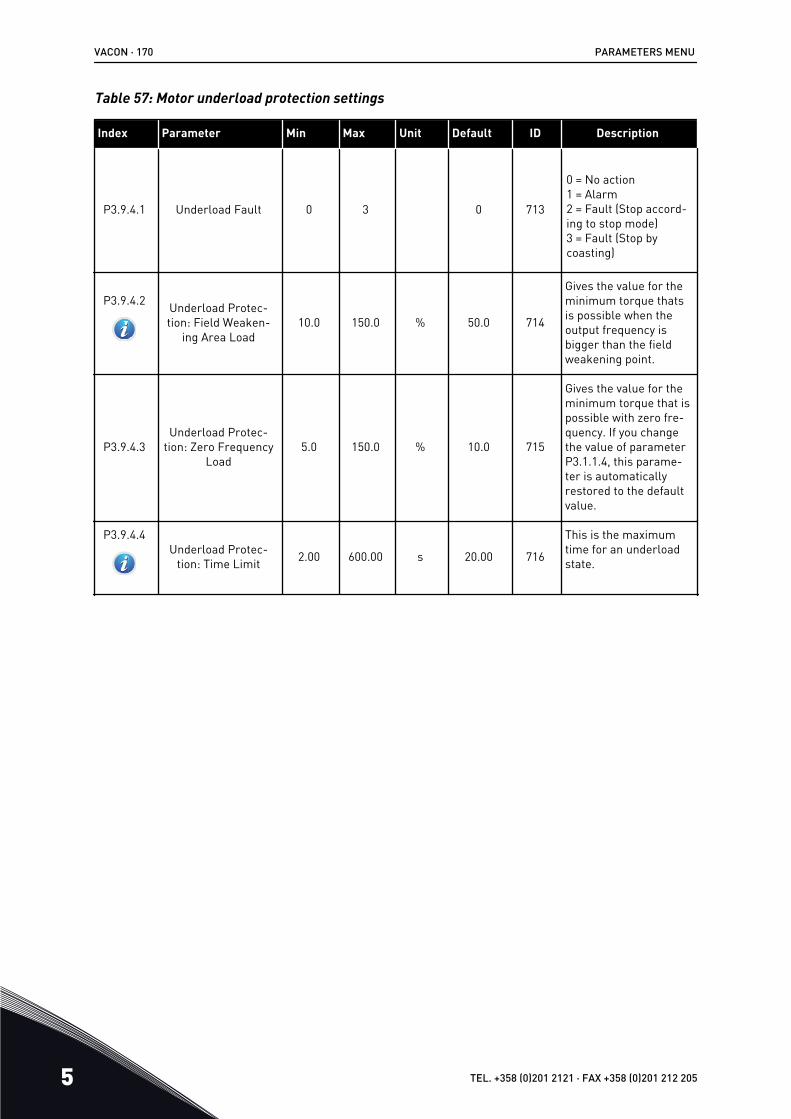
Table 57: Motor underload protection settings
Index Parameter Min Max Unit Default ID Description
P3.9.4.1 Underload Fault 0 3 0 713
0 = No action1 = Alarm2 = Fault (Stop accord-ing to stop mode)3 = Fault (Stop bycoasting)
P3.9.4.2 Underload Protec-tion: Field Weaken-
ing Area Load10.0 150.0 % 50.0 714
Gives the value for theminimum torque thatsis possible when theoutput frequency isbigger than the fieldweakening point.
P3.9.4.3Underload Protec-
tion: Zero FrequencyLoad
5.0 150.0 % 10.0 715
Gives the value for theminimum torque that ispossible with zero fre-quency. If you changethe value of parameterP3.1.1.4, this parame-ter is automaticallyrestored to the defaultvalue.
P3.9.4.4Underload Protec-
tion: Time Limit 2.00 600.00 s 20.00 716
This is the maximumtime for an underloadstate.
VACON · 170 PARAMETERS MENU
5 TEL. +358 (0)201 2121 · FAX +358 (0)201 212 205

Table 58: Quick stop settings
Index Parameter Min Max Unit Default ID Description
P3.9.5.1
Quick Stop Mode 0 2 1 1276
How the drive stopswhen the Quick stopfunction is activatedfrom DI or fieldbus.
0 = Coasting1 = Quick stop deceler-ation time2 = Stop according toStop function (P3.2.5)
P3.9.5.2
Quick Stop Activation Varies Varies DigINSlot0.2 1213
OPEN = Activated
P3.9.5.3Quick Stop Decelera-
tion Time 0.1 300.0 s 3.0 1256
P3.9.5.4Response to Quick
Stop Fault 0 2 1 744
0 = No action1 = Alarm2 = Fault (Stop accord-ing to Quick stopmode)
PARAMETERS MENU VACON · 171
24-HOUR SUPPORT +358 (0)201 212 575 · EMAIL: [email protected] 5

Table 59: Temperature input fault 1 settings
Index Parameter Min Max Unit Default ID Description
P3.9.6.1 Temperature Signal1 0 63 0 739
Selection of signals touse for alarm and faulttriggering.B0 = Temperature Sig-nal 1B1 = Temperature Sig-nal 2B2 = Temperature Sig-nal 3B3 = Temperature Sig-nal 4B4 = Temperature Sig-nal 5B5 = Temperature Sig-nal 6
The maximum value istaken from the set sig-nals and used foralarm and fault trig-gering.
NOTE!Only the 6 first tem-perature inputs aresupported (the boardsfrom slot A to slot E).
P3.9.6.2 Alarm Limit 1 -30.0 200.0 °C 130.0 741
The temperature limitfor an alarm.
NOTE!Only the inputs thatare set with parame-ter P3.9.6.1 are com-pared.
P3.9.6.3 Fault Limit 1 -30.0 200.0 °C 155.0 742
The temperature limitfor an alarm.
NOTE!Only the inputs thatare set with parame-ter P3.9.6.1 are com-pared.
VACON · 172 PARAMETERS MENU
5 TEL. +358 (0)201 2121 · FAX +358 (0)201 212 205

Table 59: Temperature input fault 1 settings
Index Parameter Min Max Unit Default ID Description
P3.9.6.4 Fault Limit Response1 0 3 2 740
0 = No response1 = Alarm2 = Fault (Stop accord-ing to stop mode)3 = Fault (Stop bycoasting)
PARAMETERS MENU VACON · 173
24-HOUR SUPPORT +358 (0)201 212 575 · EMAIL: [email protected] 5

Table 60: Temperature input fault 2 settings
Index Parameter Min Max Unit Default ID Description
P3.9.6.5 Temperature Signal2 0 63 0 763
The selection of signalsto use for alarm andfault triggering.B0 = Temperature Sig-nal 1B1 = Temperature Sig-nal 2B2 = Temperature Sig-nal 3B3 = Temperature Sig-nal 4B4 = Temperature Sig-nal 5B5 = Temperature Sig-nal 6
The maximum value istaken from the set sig-nals and used foralarm and fault trig-gering.
NOTE!Only the 6 first tem-perature inputs aresupported (the boardsfrom slot A to slot E).
P3.9.6.6 Alarm Limit 2 -30.0 200.0 °C 130.0 764
The temperature limitfor an alarm.
NOTE!Only the inputs thatare set with parame-ter P3.9.6.5 are com-pared.
P3.9.6.7 Fault Limit 2 -30.0 200.0 °C 155.0 765
The temperature limitfor an alarm.
NOTE!Only the inputs thatare set with parame-ter P3.9.6.5 are com-pared.
VACON · 174 PARAMETERS MENU
5 TEL. +358 (0)201 2121 · FAX +358 (0)201 212 205

Table 60: Temperature input fault 2 settings
Index Parameter Min Max Unit Default ID Description
P3.9.6.8 Fault Limit Response2 0 3 2 766
0 = No response1 = Alarm2 = Fault (Stop accord-ing to stop mode)3 = Fault (Stop bycoasting)
Table 61: AI low protection settings
Index Parameter Min Max Unit Default ID Description
P3.9.8.1Analogue Input Low
Protection 0 2 767
0 = No protection1 = Protection enabledin Run state2 = Protection enabledin Run and Stop state
P3.9.8.2Analogue Input Low
Fault 0 5 0 700
0 = No action1 = Alarm2 = Alarm + presetfault frequency(P3.9.1.13)3 = Alarm + previousfrequency reference4 = Fault (Stop accord-ing to stop mode)5 = Fault (Stop bycoasting)
PARAMETERS MENU VACON · 175
24-HOUR SUPPORT +358 (0)201 212 575 · EMAIL: [email protected] 5

5.10 GROUP 3.10: AUTOMATIC RESET
Table 62: Autoreset settings
Index Parameter Min Max Unit Default ID Description
P3.10.1
Automatic Reset 0 1 0 * 731 0 = Disabled1 = Enabled
P3.10.2 Restart Function 0 1 1 719
The selection of thestart mode for theAutomatic reset.
0 = Flying start1 = According toP3.2.4.
P3.10.3
Wait Time 0.10 10000.00 s 0.50 717
The wait time beforethe first reset is done.
P3.10.4
Trial Time 0.00 10000.00 s 60.00 718
When the trial time isover, and the fault isstill active, the drivewill trip.
P3.10.5
Number of Trials 1 10 4 759
The total quantity oftrials. The fault typedoes not have an effecton it. If the drive is notable to be reset withthe quantity of trialsand the set trial time, afault shows.
P3.10.6 Autoreset: Under-voltage 0 1 1 720
Autoreset permitted?
0 = No1 = Yes
P3.10.7 Autoreset: Overvolt-age 0 1 1 721
Autoreset permitted?
0 = No1 = Yes
P3.10.8 Autoreset: Overcur-rent 0 1 1 722
Autoreset permitted?
0 = No1 = Yes
VACON · 176 PARAMETERS MENU
5 TEL. +358 (0)201 2121 · FAX +358 (0)201 212 205

Table 62: Autoreset settings
Index Parameter Min Max Unit Default ID Description
P3.10.9 Autoreset: AI Low 0 1 1 723
Autoreset permitted?
0 = No1 = Yes
P3.10.10 Autoreset: Unit Over-temperature 0 1 1 724
Autoreset permitted?
0 = No1 = Yes
P3.10.11 Autoreset: MotorOvertemperature 0 1 1 725
Autoreset permitted?
0 = No1 = Yes
P3.10.12 Autoreset: ExternalFault 0 1 0 726
Autoreset permitted?
0 = No1 = Yes
P3.10.13 Autoreset: Under-load Fault 0 1 0 738
Autoreset permitted?
0 = No1 = Yes
* The selection of the application with parameter P1.2 Application gives the default value.See the default values in 12.1 The default values of parameters in the different applications.
PARAMETERS MENU VACON · 177
24-HOUR SUPPORT +358 (0)201 212 575 · EMAIL: [email protected] 5

5.11 GROUP 3.11: APPLICATION SETTINGS
Table 63: Application settings
Index Parameter Min Max Unit Default ID Description
P3.11.1 Password 0 9999 0 1806The password of theadministrator.No current function
P3.11.2 C/F Selection 0 1 0 * 1197
0 = Celsius1 = Fahrenheit
The system shows allthe temperature-rela-ted parameters andmonitoring values inthe set unit.
P3.11.3 kW/hp Selection 0 1 0 1198
0 = kW1 = hp
The system shows allthe power-relatedparameters and moni-toring values in the setunit.
P3.11.4 Multimonitor View 0 2 1 1196
The division of the dis-play of the controlpanel into sections inthe multimonitor view.
0 = 2x2 sections1 = 3x2 sections2 = 3x3 sections
VACON · 178 PARAMETERS MENU
5 TEL. +358 (0)201 2121 · FAX +358 (0)201 212 205

5.12 GROUP 3.12: TIMER FUNCTIONS
Table 64: Interval 1
Index Parameter Min Max Unit Default ID Description
P3.12.1.1 ON Time 00:00:00 23:59:59 hh:mm:ss 00:00:00 1464 The ON time
P3.12.1.2 OFF Time 00:00:00 23:59:59 hh:mm:ss 00:00:00 1465 The OFF time
P3.12.1.3 Days 1466
The days of the weekwhen a function isactive.
A checkbox selec-tionB0 = SundayB1 = MondayB2 = TuesdayB3 = WednesdayB4 = ThursdayB5 = FridayB6 = Saturday
P3.12.1.4 Assign to Channel 1468
The selection of thetime channel.
A checkbox selec-tionB0 = Time channel 1B1 = Time channel 2B2 = Time channel 3
Table 65: Interval 2
Index Parameter Min Max Unit Default ID Description
P3.12.2.1 ON Time 00:00:00 23:59:59 hh:mm:ss 00:00:00 1469 See Interval 1.
P3.12.2.2 OFF Time 00:00:00 23:59:59 hh:mm:ss 00:00:00 1470 See Interval 1.
P3.12.2.3 Days 1471 See Interval 1.
P3.12.2.4 Assign to Channel 1473 See Interval 1.
PARAMETERS MENU VACON · 179
24-HOUR SUPPORT +358 (0)201 212 575 · EMAIL: [email protected] 5

Table 66: Interval 3
Index Parameter Min Max Unit Default ID Description
P3.12.3.1 ON Time 00:00:00 23:59:59 hh:mm:ss 00:00:00 1474 See Interval 1.
P3.12.3.2 OFF Time 00:00:00 23:59:59 hh:mm:ss 00:00:00 1475 See Interval 1.
P3.12.3.3 Days 1476 See Interval 1.
P3.12.3.4 Assign to Channel 1478 See Interval 1.
Table 67: Interval 4
Index Parameter Min Max Unit Default ID Description
P3.12.4.1 ON Time 00:00:00 23:59:59 hh:mm:ss 00:00:00 1479 See Interval 1.
P3.12.4.2 OFF Time 00:00:00 23:59:59 hh:mm:ss 00:00:00 1480 See Interval 1.
P3.12.4.3 Days 1481 See Interval 1.
P3.12.4.4 Assign to Channel 1483 See Interval 1.
Table 68: Interval 5
Index Parameter Min Max Unit Default ID Description
P3.12.5.1 ON Time 00:00:00 23:59:59 hh:mm:ss 00:00:00 1484 See Interval 1.
P3.12.5.2 OFF Time 00:00:00 23:59:59 hh:mm:ss 00:00:00 1485 See Interval 1.
P3.12.5.3 Days 1486 See Interval 1.
P3.12.5.4 Assign to Channel 1488 See Interval 1.
VACON · 180 PARAMETERS MENU
5 TEL. +358 (0)201 2121 · FAX +358 (0)201 212 205

Table 69: Timer 1
Index Parameter Min Max Unit Default ID Description
P3.12.6.1 Duration 0 72000 s 0 1489The time that the timerruns when it is activa-ted by DI.
P3.12.6.2 Timer 1 DigINSlot0.1 447
The rising edge startsTimer 1 that is pro-grammed in Group3.12.
P3.12.6.3 Assign to Channel 1490
The selection of thetime channel.
A checkbox selec-tionB0 = Time channel 1B1 = Time channel 2B2 = Time channel 3
Table 70: Timer 2
Index Parameter Min Max Unit Default ID Description
P3.12.7.1 Duration 0 72000 s 0 1491 See Timer 1.
P3.12.7.2 Timer 2 DigINSlot0.1 448 See Timer 1.
P3.12.7.3 Assign to Channel 1492 See Timer 1.
Table 71: Timer 3
Index Parameter Min Max Unit Default ID Description
P3.12.8.1 Duration 0 72000 s 0 1493 See Timer 1.
P3.12.8.2 Timer 3 DigINSlot0.1 449 See Timer 1.
P3.12.8.3 Assign to Channel 1494 See Timer 1.
PARAMETERS MENU VACON · 181
24-HOUR SUPPORT +358 (0)201 212 575 · EMAIL: [email protected] 5

5.13 GROUP 3.13: PID CONTROLLER 1
Table 72: PID controller 1 basic settings
Index Parameter Min Max Unit Default ID Description
P3.13.1.1 PID Gain 0.00 1000.00 % 100.00 118
If the value of theparameter is set to100%, a change of 10%in the error value cau-ses the controller out-put to change by 10%.
P3.13.1.2 PID Integration Time 0.00 600.00 s 1.00 119
If this parameter is setto 1,00 s, a change of10% in the error valuecauses the controlleroutput to change by10.00%/s.
P3.13.1.3 PID Derivation Time 0.00 100.00 s 0.00 132
If this parameter is setto 1,00 s, a change of10% in the error valueduring 1.00 s causesthe controller output tochange by 10.00%.
P3.13.1.4 Process Unit Selec-tion 1 46 1 1036
Make a selection of theunit for the actualvalue.
1 = %2 = 1/min3 = rpm4 = ppm5 = pps6 = l/s7 = l/min8 = l/h9 = kg/s10 = kg/min11 = kg/h12 = m3/s13 = m3/min14 = m3/h15 = m/s16 = mbar17= bar18 = Pa19 = kPa20 = mVS
VACON · 182 PARAMETERS MENU
5 TEL. +358 (0)201 2121 · FAX +358 (0)201 212 205

Table 72: PID controller 1 basic settings
Index Parameter Min Max Unit Default ID Description
P3.13.1.4 Process Unit Selec-tion 1 46 1 1036
21 = kW22 = °C23 = gal/s24 = gal/min25 = gal/h26 = lb/s27 = lb/min28 = lb/h29 = ft3/s30 = ft3/min31 = ft3/h32 = ft/s33 = in wg34 = ft wg35 = SPI36 = lb/in237 = psig38 = hp39 = °F40 = ft41 = inch42 = mm43 = cm44 = m45 = gpm46 = cfm
P3.13.1.5 Process Unit Min Varies Varies Varies 0 1033
The value in the proc-ess units at a 0% feed-back or setpoint. Usethe scaling to monitoronly. The PID control-ler uses the percent-age internally for feed-backs and setpoints.
P3.13.1.6 Process Unit Max Varies Varies Varies 100 1034 See above.
P3.13.1.7 Process Unit Deci-mals 0 4 2 1035
The quantity of deci-mals of the processunit value.
P3.13.1.8 Error Inversion 0 1 0 340
0 = Normal (Feedback< Setpoint -> IncreasePID output)1 = Inverted (Feedback< Setpoint -> DecreasePID output )
PARAMETERS MENU VACON · 183
24-HOUR SUPPORT +358 (0)201 212 575 · EMAIL: [email protected] 5

Table 72: PID controller 1 basic settings
Index Parameter Min Max Unit Default ID Description
P3.13.1.9
Dead Band Varies Varies Varies 0 1056
The dead band areaaround the setpoint inprocess units. The PIDoutput is locked if thefeedback stays in thedead band area for theset time.
P3.13.1.10
Dead Band Delay 0.00 320.00 s 0.00 1057
If the feedback stays inthe dead band area forthe set time, the outputis locked.
VACON · 184 PARAMETERS MENU
5 TEL. +358 (0)201 2121 · FAX +358 (0)201 212 205

Table 73: Setpoint settings
Index Parameter Min Max Unit Default ID Description
P3.13.2.1 Keypad Setpoint 1 Varies Varies Varies 0 167
P3.13.2.2 Keypad Setpoint 2 Varies Varies Varies 0 168
P3.13.2.3 Setpoint Ramp Time 0.00 300.0 s 0.00 1068
Gives the rising and fall-ing ramp times for thesetpoint changes. Thatis, the time to changefrom the minimum tothe maximum.
P3.13.2.4 PID Setpoint BoostActivation Varies Varies DigIN
Slot0.1 1046 OPEN = No boostCLOSED = Boost
P3.13.2.5 PID Select Setpoint Varies Varies DigINSlot0.1 * 1047 OPEN = Setpoint 1
CLOSED = Setpoint 2
P3.13.2.6 Setpoint Source 1Selection 0 32 3 * 332
0 = Not used1 = Keypad setpoint 12 = Keypad setpoint 23 = AI14 = AI25 = AI36 = AI47 = AI58 = AI69 = ProcessDataIn110 = ProcessDataIn211 = ProcessDataIn312 = ProcessDataIn413 = ProcessDataIn514 = ProcessDataIn615 = ProcessDataIn7
PARAMETERS MENU VACON · 185
24-HOUR SUPPORT +358 (0)201 212 575 · EMAIL: [email protected] 5

Table 73: Setpoint settings
Index Parameter Min Max Unit Default ID Description
P3.13.2.6 Setpoint Source 1Selection 0 32 3 * 332
16 = ProcessDataIn817 = Temperature input118 = Temperature input219 = Temperature input320 = Temperature input421 = Temperature input522 = Temperature input623 = Block Out.124 = Block Out.225 = Block Out.326 = Block Out.427 = Block Out.528 = Block Out.629 = Block Out.730 = Block Out.831 = Block Out.9
P3.13.2.6 Setpoint Source 1Selection 0 32 3 * 332
The AIs and the Proc-essDataIn show as per-centages (0.00-100.00%)and use the setpointminimum and maximumfor scaling.
NOTE!The ProcessDataIn sig-nals use 2 decimals.
P3.13.2.7 Setpoint 1 Minimum Varies Varies % 0.00 1069The minimum value atthe analogue signal min-imum.
P3.13.2.8 Setpoint 1 Maximum Varies Varies % 100.00 1070The maximum value atthe analogue signalmaximum.
P3.13.2.9 Setpoint 1 Boost -2.0 2.0 x 1.0 1071It is possible to boost thesetpoint with a digitalinput.
P3.13.2.10 Setpoint Source 2Selection 0 Varies 2 * 431 See P3.13.2.6.
P3.13.2.11 Setpoint 2 Minimum Varies Varies % 0.00 1073The minimum value atthe analogue signal min-imum.
VACON · 186 PARAMETERS MENU
5 TEL. +358 (0)201 2121 · FAX +358 (0)201 212 205

Table 73: Setpoint settings
Index Parameter Min Max Unit Default ID Description
P3.13.2.12 Setpoint 2 Maximum Varies Varies % 100.00 1074The maximum value atthe analogue signalmaximum.
P3.13.2.13 Setpoint 2 Boost -2.0 2.0 x 1.0 1078 See P3.13.2.9.
* = The selection of the application with parameter P1.2 Application gives the default value.See the default values in 12.1 The default values of parameters in the different applications.
PARAMETERS MENU VACON · 187
24-HOUR SUPPORT +358 (0)201 212 575 · EMAIL: [email protected] 5

Table 74: Feedback settings
Index Parameter Min Max Unit Default ID Description
P3.13.3.1 Feedback Function 1 9 1 * 333
1 = Only Source1 in use2 = SQRT(Source1);(Flow=Constant xSQRT(Pressure))3 = SQRT(Source1-Source 2)4 = SQRT(Source 1) +SQRT (Source 2)5 = Source 1 + Source 26 = Source 1 - Source 27 = MIN (Source 1,Source 2)8 = MAX (Source 1,Source 2)9 = MEAN (Source 1,Source 2)
P3.13.3.2 Feedback FunctionGain -1000.0 1000.0 % 100.0 1058
Use, for example, withthe value 2 in the Feed-back function.
P3.13.3.3 Feedback 1 SourceSelection 0 30 2 * 334
0 = Not used1 = AI12 = AI23 = AI34 = AI45 = AI56 = AI67 = ProcessDataIn18 = ProcessDataIn29 = ProcessDataIn310 = ProcessDataIn411 = ProcessDataIn512 = ProcessDataIn613 = ProcessDataIn714 = ProcessDataIn815 = Temperature input 1
VACON · 188 PARAMETERS MENU
5 TEL. +358 (0)201 2121 · FAX +358 (0)201 212 205

Table 74: Feedback settings
Index Parameter Min Max Unit Default ID Description
P3.13.3.3 Feedback 1 SourceSelection 0 30 2 * 334
16 = Temperature input 217 = Temperature input 318 = Temperature input 419 = Temperature input 520 = Temperature input 621 = Block Out.122 = Block Out.223 = Block Out.324 = Block Out.425 = Block Out.526 = Block Out.627 = Block Out.728 = Block Out.829 = Block Out.930 = Block Out.10
P3.13.3.3 Feedback 1 SourceSelection 0 30 2 * 334
The AIs and the Process-DataIn show as percen-tages (0.00-100.00%) anduse the setpoint mini-mum and maximum forscaling.
NOTE!The ProcessDataIn sig-nals use 2 decimals.If temperature inputsare selected, you mustset the values of param-eters P3.13.1.5 ProcessUnit Min and P3.13.1.6Process Unit Max toagree with the scale ofthe temperature meas-urement board:
ProcessUnitMin = -50 °CProcessUnitMax = 200°C
P3.13.3.4 Feedback 1 Minimum -200.00 200.00 % 0.00 336The minimum value atthe analogue signal mini-mum.
P3.13.3.5 Feedback 1 Maxi-mum -200.00 200.00 % 100.00 337
The maximum value atthe analogue signal max-imum.
P3.13.3.6 Feedback 2 SourceSelection 0 20 0 335 See P3.13.3.3.
PARAMETERS MENU VACON · 189
24-HOUR SUPPORT +358 (0)201 212 575 · EMAIL: [email protected] 5

Table 74: Feedback settings
Index Parameter Min Max Unit Default ID Description
P3.13.3.7 Feedback 2 Minimum -200.00 200.00 % 0.00 338The minimum value atthe analogue signal mini-mum.
M3.13.3.8 Feedback 2 Maxi-mum -200.00 200.00 % 100.00 339
The maximum value atthe analogue signal max-imum.
* = The selection of the application with parameter P1.2 Application gives the default value.See the default values in 12.1 The default values of parameters in the different applications.
VACON · 190 PARAMETERS MENU
5 TEL. +358 (0)201 2121 · FAX +358 (0)201 212 205

Table 75: Feedback settings
Index Parameter Min Max Unit Default ID Description
P3.13.3.1 Feedback Function 1 9 1 * 333
1 = Only Source1 in use2 = SQRT(Source1);(Flow=Constant xSQRT(Pressure))3 = SQRT(Source1-Source 2)4 = SQRT(Source 1) +SQRT (Source 2)5 = Source 1 + Source 26 = Source 1 - Source 27 = MIN (Source 1,Source 2)8 = MAX (Source 1,Source 2)9 = MEAN (Source 1,Source 2)
P3.13.3.2 Feedback FunctionGain -1000.0 1000.0 % 100.0 1058
Use, for example, withthe value 2 in the Feed-back function.
P3.13.3.3 Feedback 1 SourceSelection 0 30 2 * 334
0 = Not used1 = AI12 = AI23 = AI34 = AI45 = AI56 = AI67 = ProcessDataIn18 = ProcessDataIn29 = ProcessDataIn310 = ProcessDataIn411 = ProcessDataIn512 = ProcessDataIn613 = ProcessDataIn714 = ProcessDataIn815 = Temperature input 1
PARAMETERS MENU VACON · 191
24-HOUR SUPPORT +358 (0)201 212 575 · EMAIL: [email protected] 5

Table 75: Feedback settings
Index Parameter Min Max Unit Default ID Description
P3.13.3.3 Feedback 1 SourceSelection 0 30 2 * 334
16 = Temperature input 217 = Temperature input 318 = Temperature input 419 = Temperature input 520 = Temperature input 621 = Block Out.122 = Block Out.223 = Block Out.324 = Block Out.425 = Block Out.526 = Block Out.627 = Block Out.728 = Block Out.829 = Block Out.930 = Block Out.10
P3.13.3.3 Feedback 1 SourceSelection 0 30 2 * 334
The AIs and the Process-DataIn show as percen-tages (0.00-100.00%) anduse the setpoint mini-mum and maximum forscaling.
NOTE!The ProcessDataIn sig-nals use 2 decimals.If temperature inputsare selected, you mustset the values of param-eters P3.13.1.5 ProcessUnit Min and P3.13.1.6Process Unit Max toagree with the scale ofthe temperature meas-urement board:
ProcessUnitMin = -50 °CProcessUnitMax = 200°C
P3.13.3.4 Feedback 1 Minimum -200.00 200.00 % 0.00 336The minimum value atthe analogue signal mini-mum.
P3.13.3.5 Feedback 1 Maxi-mum -200.00 200.00 % 100.00 337
The maximum value atthe analogue signal max-imum.
P3.13.3.6 Feedback 2 SourceSelection 0 20 0 335 See P3.13.3.3.
VACON · 192 PARAMETERS MENU
5 TEL. +358 (0)201 2121 · FAX +358 (0)201 212 205

Table 75: Feedback settings
Index Parameter Min Max Unit Default ID Description
P3.13.3.7 Feedback 2 Minimum -200.00 200.00 % 0.00 338The minimum value atthe analogue signal mini-mum.
M3.13.3.8 Feedback 2 Maxi-mum -200.00 200.00 % 100.00 339
The maximum value atthe analogue signal max-imum.
* = The selection of the application with parameter P1.2 Application gives the default value.See the default values in 12.1 The default values of parameters in the different applications.
Table 76: Feedforward settings
Index Parameter Min Max Unit Default ID Description
P3.13.4.1Feedforward Func-
tion 1 9 1 1059
See P3.13.3.1
P3.13.4.2 Feedforward Func-tion Gain -1000 1000 % 100.0 1060 See P3.13.3.2
P3.13.4.3 Feedforward 1Source Selection 0 25 0 1061 See P3.13.3.3
P3.13.4.4 Feedforward 1 Mini-mum -200.00 200.00 % 0.00 1062 See P3.13.3.4
P3.13.4.5 Feedforward 1 Maxi-mum -200.00 200.00 % 100.00 1063 See P3.13.3.5
P3.13.4.6 Feedforward 2Source Selection 0 25 0 1064 See P3.13.3.6
P3.13.4.7 Feedforward 2 Min -200.00 200.00 % 0.00 1065 See P3.13.3.7
P3.13.4.8 Feedforward 2 Max -200.00 200.00 % 100.00 1066 See M3.13.3.8
PARAMETERS MENU VACON · 193
24-HOUR SUPPORT +358 (0)201 212 575 · EMAIL: [email protected] 5

Table 77: Sleep function settings
Index Parameter Min Max Unit Default ID Description
P3.13.5.1SP1 Sleep Fre-
quency Limit 0.00 320.00 Hz 0.00 1016
The drive goes to theSleep mode when theoutput frequencystays below this limitfor a longer timethan is specified byparameter SP1 SleepDelay, P3.13.5.2.
P3.13.5.2
SP1 Sleep Delay 0 3000 s 0 1017
The minimum quan-tity of time the fre-quency stays belowP3.13.5.1 before thedrive stops.
P3.13.5.3
SP1 Wake Up Level Varies Varies Varies 0.0000 1018
Gives the level forthe supervision of thePID feedback valuewake-up. Uses theselected processunits.
P3.13.5.4 SP1 Wake Up Mode 0 1 0 1019
Select the operationfor parameterP3.13.5.3 SP1 WakeUp Level.
0=Absolute Level1=Relative Setpoint
P3.13.5.5
SP1 Sleep Boost -9999 9999 P3.13.1.4 0 1793
Setpoint 1 boost
P3.13.5.6 SP1 Sleep BoostMaximum Time 1 300 s 30 1795 SP1 sleep boost
timeout
P3.13.5.7 SP2 Sleep Fre-quency 0.00 320.00 Hz 0.00 1075 See P3.13.5.1
P3.13.5.8 SP2 Sleep Delay 0 3000 s 0 1076 See P3.13.5.2
P3.13.5.9 SP2 Wake Up Level Varies Varies Varies 0.0 1077 See P3.13.5.3
P3.13.5.10 SP2 Wake Up Mode 0 1 0 1020
Select the operationfor parameterP3.13.5.9 SP2 WakeUp Level.
0=Absolute Level1=Relative Setpoint
VACON · 194 PARAMETERS MENU
5 TEL. +358 (0)201 2121 · FAX +358 (0)201 212 205

Table 77: Sleep function settings
Index Parameter Min Max Unit Default ID Description
P3.13.5.11 SP2 Sleep Boost -9999 9999 P3.13.1.4 0 1794 See P3.13.5.4
P3.13.5.12 SP2 Sleep BoostMaximum Time 1 300 s 30 1796 See P3.13.5.5
Table 78: Feedback supervision parameters
Index Parameter Min Max Unit Default ID Description
P3.13.6.1Enable Feedback
Supervision 0 1 0 735 0 = Disabled1 = Enabled
P3.13.6.2
Upper Limit Varies Varies Varies Varies 736
The supervision of theupper actual/processvalue.
P3.13.6.3
Lower Limit Varies Varies Varies Varies 758
The supervision of thelower actual/processvalue.
P3.13.6.4
Delay 0 30000 s 0 737
If the PID Feedbacksignal does not stay inthe range, and thiscontinues longer thanthe delay, a fault or analarm shows.
P3.13.6.5 Response to PIDSupervision Fault 0 3 2 749
0 = No action1 = Alarm2 = Fault (Stop accord-ing to stop mode)3 = Fault (Stop bycoasting)
PARAMETERS MENU VACON · 195
24-HOUR SUPPORT +358 (0)201 212 575 · EMAIL: [email protected] 5

Table 79: Pressure loss compensation parameters
Index Parameter Min Max Unit Default ID Description
P3.13.7.1
Enable Setpoint 1 0 1 0 1189
Enables pressure losscompensation for thesetpoint 1.
0 = Disabled1 = Enabled
P3.13.7.2Setpoint 1 Max Com-
pensation Varies Varies Varies Varies 1190
The value that is added(proportionally) in pro-portion to the fre-quency. Setpoint com-pensation = max com-pensation * (FreqOut-MinFreq)/(MaxFreq-MinFreq).
P3.13.7.3 Enable Setpoint 2 0 1 0 1191 See P3.13.7.1.
P3.13.7.4 Setpoint 2 Max Com-pensation Varies Varies Varies Varies 1192 See P3.13.7.2.
VACON · 196 PARAMETERS MENU
5 TEL. +358 (0)201 2121 · FAX +358 (0)201 212 205

Table 80: Soft fill settings
Index Parameter Min Max Unit Default ID Description
P3.13.8.1
Soft Fill Function 0 2 0 1094 0 = Disabled1 = Enabled, Level2 = Enabled, Timeout
P3.13.8.2
Soft Fill Frequency 0.00 P3.3.1.2 Hz 20.00 1055
Use this frequency ref-erence when the Softfill function is active.
P3.13.8.3
Soft Fill Level Varies Varies Varies 0.0000 1095
The drive operates atthe PID start frequencyuntil the feedback goesto this value. Then thecontroller starts tocontrol.
NOTE!This parameter isused only if P3.13.8.1= 1 Enabled (Level).
P3.13.8.4
Soft Fill Timeout 0 30000 s 0 1096
When P3.13.8.1 = 1Enabled (Level):Parameter Soft FillTimeout gives thetimeout for the soft filllevel, after which thesoft fill fault shows.
0 = No timeout, nofault triggering
When P3.13.8.1 = 2Enabled (Timeout):The drive operates atthe soft fill frequency(P3.13.8.2) until thetime specified by thisparameter goes. Thenthe PID controllerstarts to control.
PARAMETERS MENU VACON · 197
24-HOUR SUPPORT +358 (0)201 212 575 · EMAIL: [email protected] 5

Table 80: Soft fill settings
Index Parameter Min Max Unit Default ID Description
P3.13.8.5 PID Soft Fill TimeoutResponse 0 3 2 738
0 = No action1 = Alarm2 = Fault (Stop accord-ing to stop mode)3 = Fault (Stop bycoasting)
NOTE!This parameter isused only if P3.13.8.1= 1 Enabled (Level)
VACON · 198 PARAMETERS MENU
5 TEL. +358 (0)201 2121 · FAX +358 (0)201 212 205

Table 81: Input pressure supervision parameters
Index Parameter Min Max Unit Default ID Description
P3.13.9.1 Enable Super-vision 0 1 0 1685
0 = Disabled1 = Enabled
Enables the input pres-sure supervision.
P3.13.9.2 SupervisionSignal 0 23 0 1686
The source of the sig-nal of the input pres-sure measurement.
0 = Analogue input 11 = Analogue input 22 = Analogue input 33 = Analogue input 44 = Analogue input 55 = Analogue input 66 = ProcessDataIn1(0-100%)7 = ProcessDataIn2(0-100%)8 = ProcessDataIn3(0-100%)9 = ProcessDataIn4(0-100%)10 = ProcessDataIn5(0-100%)11 = ProcessDataIn6(0-100%)12 = ProcessDataIn7(0-100%)13 = ProcessDataIn8(0-100%)14 = Block Out.115 = Block Out.216 = Block Out.317 = Block Out.418 = Block Out.519 = Block Out.620 = Block Out.721 = Block Out.822 = Block Out.923 = Block Out.10
PARAMETERS MENU VACON · 199
24-HOUR SUPPORT +358 (0)201 212 575 · EMAIL: [email protected] 5

Table 81: Input pressure supervision parameters
Index Parameter Min Max Unit Default ID Description
P3.13.9.3 SupervisionUnit Selection 1 9 Varies 3 1687
1 = %2 = mbar3 = bar4 = Pa5 = kPa6 = PSI7 = mmHg8 = Torr9 = lb/in2
P3.13.9.4 SupervisionUnit Decimals 0 4 2 1688 The selection of the
quantity of decimals.
P3.13.9.5Supervision
Unit MinimumValue
Varies Varies P3.13.9.3 0.00 1689The signal value mini-mum agrees to, forexample, 4mA, and thesignal value maximumagrees to 20mA. Thescaling of the values isdone linearly betweenthese 2.
P3.13.9.6Supervision
Unit MaximumValue
Varies Varies P3.13.9.3 10.00 1690
P3.13.9.7 SupervisionAlarm Level Varies Varies P3.13.9.3 Varies 1691
An alarm shows (faultID 1363) if the supervi-sion signal stays belowthe alarm level longerthan the time set inP3.13.9.9.
P3.13.9.8 SupervisionFault Level Varies Varies P3.13.9.3 0.10 1692
A fault shows (fault ID1409) if the supervisionsignal stays below thefault level longer thanthe time set inP3.13.9.9.
P3.13.9.9 SupervisionFault Delay 0.00 60.00 s 5.00 1693
The delay time duringwhich to show thesupervision alarm orfault, if the supervisionsignal stays below thealarm/fault level lon-ger than specified bythis parameter.
P3.13.9.10 PID SetpointReduction 0.0 100.0 % 10.0 1694
Gives the rate of thesetpoint reduction ofthe PID controllerwhen the alarm for theinput pressure supervi-sion is active.
VACON · 200 PARAMETERS MENU
5 TEL. +358 (0)201 2121 · FAX +358 (0)201 212 205

Table 81: Input pressure supervision parameters
Index Parameter Min Max Unit Default ID Description
V3.13.9.11 Input Pressure P3.13.9.5 P3.13.9.6 P3.13.9.3 Varies 1695
The monitoring valuefor the set signal of theinput pressure supervi-sion. The acaling valueas is in P3.13.9.4.
Table 82: Sleep - no demand detected
Index Parameter Min Max Unit Default ID Description
P3.13.10.1Sleep No
Demand Detec-tion Enable
0 1 0 1649
Enables the Sleep, nodemand detected(SNDD) function.
0 = Disabled1 = Enabled
P3.13.10.2 SNDD Error Hys-teresis 0 99999.9 P3.13.1.4 0.5 1658
Semi-amplitude of thesymmetrical processerror band for nodemand detection(0±hysteresis)
P3.13.10.3 SNDD FrequencyHysteresis 1.00 P3.3.1.2 Hz 3.00 1663
Frequency hysteresisfor no demand detec-tion
P3.13.10.4 SNDD Supervi-sion Time 0 600 s 120 1668 Supervision time for
no demand detection
P3.13.10.5 SNDD Actual Add 0.1 P3.13.10.2 P3.13.1.4 0.5 1669
A bias added to theactual PID setpointvalue to decrease thePID output and to goto sleep.
PARAMETERS MENU VACON · 201
24-HOUR SUPPORT +358 (0)201 212 575 · EMAIL: [email protected] 5

Table 83: Multi-setpoint parameters
Index Parameter Min Max Unit Default ID Description
P3.13.12.1 Multi-Setpoint0 P3.13.1.5 P3.13.1.6 P3.13.1.4 0.0 15560 Preset setpoint value
P3.13.12.2 Multi-Setpoint1 P3.13.1.5 P3.13.1.6 P3.13.1.4 0.0 15561 Preset setpoint value
P3.13.12.3 Multi-Setpoint2 P3.13.1.5 P3.13.1.6 P3.13.1.4 0.0 15562 Preset setpoint value
P3.13.12.4 Multi-Setpoint3 P3.13.1.5 P3.13.1.6 P3.13.1.4 0.0 15563 Preset setpoint value
P3.13.12.5 Multi-Setpoint4 P3.13.1.5 P3.13.1.6 P3.13.1.4 0.0 15564 Preset setpoint value
P3.13.12.6 Multi-Setpoint5 P3.13.1.5 P3.13.1.6 P3.13.1.4 0.0 15565 Preset setpoint value
P3.13.12.7 Multi-Setpoint6 P3.13.1.5 P3.13.1.6 P3.13.1.4 0.0 15566 Preset setpoint value
P3.13.12.8 Multi-Setpoint7 P3.13.1.5 P3.13.1.6 P3.13.1.4 0.0 15567 Preset setpoint value
P3.13.12.9 Multi-Setpoint8 P3.13.1.5 P3.13.1.6 P3.13.1.4 0.0 15568 Preset setpoint value
P3.13.12.10 Multi-Setpoint9 P3.13.1.5 P3.13.1.6 P3.13.1.4 0.0 15569 Preset setpoint value
P3.13.12.11 Multi-Setpoint10 P3.13.1.5 P3.13.1.6 P3.13.1.4 0.0 15570 Preset setpoint value
P3.13.12.12 Multi-Setpoint11 P3.13.1.5 P3.13.1.6 P3.13.1.4 0.0 15571 Preset setpoint value
P3.13.12.13 Multi-Setpoint12 P3.13.1.5 P3.13.1.6 P3.13.1.4 0.0 15572 Preset setpoint value
P3.13.12.14 Multi-Setpoint13 P3.13.1.5 P3.13.1.6 P3.13.1.4 0.0 15573 Preset setpoint value
P3.13.12.15 Multi-Setpoint14 P3.13.1.5 P3.13.1.6 P3.13.1.4 0.0 15574 Preset setpoint value
P3.13.12.16 Multi-Setpoint15 P3.13.1.5 P3.13.1.6 P3.13.1.4 0.0 15575 Preset setpoint value
P3.13.12.17 Multi-SetpointSelection 0
DigINSlot0.1 15576
Digital input selection:Multi-Setpoint selec-tion (bit 0)
VACON · 202 PARAMETERS MENU
5 TEL. +358 (0)201 2121 · FAX +358 (0)201 212 205

Table 83: Multi-setpoint parameters
Index Parameter Min Max Unit Default ID Description
P3.13.12.18 Multi-SetpointSelection 1
DigINSlot0.1 15577
Digital input selection:Multi-Setpoint selec-tion (bit 1)
P3.13.12.19 Multi-SetpointSelection 2
DigINSlot0.1 15578
Digital input selection:Multi-Setpoint selec-tion (bit 2)
P3.13.12.20 Multi-SetpointSelection 3
DigINSlot0.1 15579
Digital input selection:Multi-Setpoint selec-tion (bit 3)
PARAMETERS MENU VACON · 203
24-HOUR SUPPORT +358 (0)201 212 575 · EMAIL: [email protected] 5

5.14 GROUP 3.14: EXTERNAL PID CONTROLLER
Table 84: Basic settings for the external PID controller
Index Parameter Min Max Unit Default ID Description
P3.14.1.1 Enable External PID 0 1 0 1630 0 = Disabled1 = Enabled
P3.14.1.2 Start Signal DigINSlot0.2 1049
OPEN = PID2 in stopmodeCLOSED = PID2 regu-lating
If the PID2 controller isnot enabled in theBasic menu for PID2,this parameter has noeffect.
P3.14.1.3 Output in Stop 0.0 100.0 % 0.0 1100
The output value of thePID controller as apercentage of its maxi-mum output valuewhen it is stopped froma digital output.
P3.14.1.4 PID Gain 0.00 1000.00 % 100.00 1631 See P3.13.1.1
P3.14.1.5 PID Integration Time 0.00 600.00 s 1.00 1632 See P3.13.1.2
P3.14.1.6 PID Derivation Time 0.00 100.00 s 0.00 1633 See P3.13.1.3
P3.14.1.7 Process Unit Selec-tion 0 46 0 1635 See P3.13.1.4
P3.14.1.8 Process Unit Min Varies Varies Varies 0 1664 See P3.13.1.5
P3.14.1.9 Process Unit Max Varies Varies Varies 100 1665 See P3.13.4.6
P3.14.1.10 Process Unit Deci-mals 0 4 2 1666
P3.14.1.11 Error Inversion 0 1 0 1636 See P3.13.18
P3.14.1.12 Dead Band Varies Varies Varies 0.0 1637 See P3.13.1.9
P3.14.1.13 Dead Band Delay 0.00 320.00 s 0.00 1638 See P3.13.1.10
VACON · 204 PARAMETERS MENU
5 TEL. +358 (0)201 2121 · FAX +358 (0)201 212 205

Table 85: Setpoints of the external PID controller
Index Parameter Min Max Unit Default ID Description
P3.14.2.1 Keypad Setpoint 1 P3.14.1.8
P3.14.1.8 Varies 0.00 1640
P3.14.2.2 Keypad Setpoint 2 P3.14.1.8
P3.14.1.9 Varies 0.00 1641
P3.14.2.3 Setpoint Ramp Time 0.00 300.00 s 0.00 1642
P3.14.2.4 Select Setpoint DigINSlot0.1 1048 OPEN = Setpoint 1
CLOSED = Setpoint 2
PARAMETERS MENU VACON · 205
24-HOUR SUPPORT +358 (0)201 212 575 · EMAIL: [email protected] 5

Table 85: Setpoints of the external PID controller
Index Parameter Min Max Unit Default ID Description
P3.14.2.5 Setpoint Source 1Selection 0 32 1 1643
0 = Not Used1 = Keypad Setpoint 12 = Keypad Setpoint 23 = AI14 = AI25 = AI36 = AI47 = AI58 = AI69 =ProcessDataIn110 =ProcessDataIn211 =ProcessDataIn312 =ProcessDataIn413 =ProcessDataIn514 =ProcessDataIn615 =ProcessDataIn716 =ProcessDataIn817 = Temperature Input118 = Temperature Input219 = Temperature Input320 = Temperature Input421 = Temperature Input522 = Temperature Input623 = Block Out.124 = Block Out.225 = Block Out.326 = Block Out.427 = Block Out.528 = Block Out.629 = Block Out.730 = Block Out.831 = Block Out.932 = Block Out.10
The AIs and the Proc-essDataIn show as per-centages (0.00-100.00%)and use the setpointminimum and maximumfor scaling.
VACON · 206 PARAMETERS MENU
5 TEL. +358 (0)201 2121 · FAX +358 (0)201 212 205

Table 85: Setpoints of the external PID controller
Index Parameter Min Max Unit Default ID Description
P3.14.2.5 Setpoint Source 1Selection 0 32 1 1643
NOTE!The ProcessDataIn sig-nals use 2 decimals.If temperature inputsare selected, you mustset the values ofparameters P3.14.1.8Process Unit Max andP3.14.1.9 Process UnitMin to agree with thescale of the tempera-ture measurementboard:
ProcessUnitMin = -50°CProcessUnitMax = 200°C
P3.14.2.6 Setpoint 1 Minimum Varies Varies % 0.00 1644The minimum value atthe analogue signal min-imum.
P3.14.2.7 Setpoint 1 Maximum Varies Varies % 100.00 1645The maximum value atthe analogue signalmaximum.
P3.14.2.8 Setpoint Source 2Selection 0 32 0 1646 See P3.14.2.5.
P3.14.2.9 Setpoint 2 Minimum Varies Varies % 0.00 1647The minimum value atthe analogue signal min-imum.
P3.14.2.10 Setpoint 2 Maximum Varies Varies % 100.00 1648The maximum value atthe analogue signalmaximum.
PARAMETERS MENU VACON · 207
24-HOUR SUPPORT +358 (0)201 212 575 · EMAIL: [email protected] 5

Table 86: Feedback of the external PID controller
Index Parameter Min Max Unit Default ID Description
P3.14.3.1 Feedback Function 1 9 1 1650 See P3.13.3.1
P3.14.3.2 Feedback FunctionGain -1000.0 1000.0 % 100.0 1651 See P3.13.3.2
P3.14.3.3 Feedback 1 SourceSelection 0 30 1 1652 See P3.13.3.3
P3.14.3.4 Feedback 1 Minimum Varies Varies % 0.00 1653The minimum value atthe analogue signalminimum.
P3.14.3.5 Feedback 1 Maxi-mum Varies Varies % 100.00 1654
The maximum value atthe analogue signalmaximum.
P3.14.3.6 Feedback 2 SourceSelection 0 30 2 1655 See P3.13.3.6.
P3.14.3.7 Feedback 2 Minimum Varies Varies % 0.00 1656The minimum value atthe analogue signalminimum.
P3.14.3.8 Feedback 2 Maxi-mum Varies Varies % 100.00 1657
The maximum value atthe analogue signalmaximum.
Table 87: Process supervision of the external PID controller
Index Parameter Min Max Unit Default ID Description
P3.14.4.1 Enable Supervision 0 1 0 1659 0 = Disabled1 = Enabled
P3.14.4.2 Upper Limit Varies Varies Varies Varies 1660 See P3.13.6.2
P3.14.4.3 Lower Limit Varies Varies Varies Varies 1661 See P3.13.6.3
P3.14.4.4 Delay 0 30000 s 0 1662
If the signal does notstay in the range, andthis continues longerthan the delay, a faultor an alarm shows.
P3.14.4.5Response to External
PID SupervisionFault
0 3 2 757See P3.9.1.2
VACON · 208 PARAMETERS MENU
5 TEL. +358 (0)201 2121 · FAX +358 (0)201 212 205

5.15 GROUP 3.15: MULTIPUMP
Table 88: Multipump parameters
Index Parameter Min Max Unit Default ID Description
P3.15.1
Multipump Mode 0 2 0 * 1785 0 = Single Drive1 = Multifollower2 = Multimaster
P3.15.2
Number of Pumps 1 8 1 * 1001
The total number ofmotors (pumps/fans)used in the Multipumpsystem.
P3.15.3
Pump ID Number 0 10 0 1500
Each drive in the pumpsystem must have aunique sequence (ID)number, always startfrom 1.
NOTE!Use this parameteronly if you selectedthe Multifollower orMultimaster modewith P3.15.1.
P3.15.4Start and Feedback
Signals 0 2 1 1782
Is the start signaland/or the PID feed-back signal connectedto the drive?
0 = Not Connected1 = Only Start SignalConnected2 = Both Signals Con-nected
P3.15.5
Pump Interlocking 0 1 1 * 1032
Enable or disable theinterlocks. Interlockstell the system if amotor is connected ornot.
0 = Not used1 = Enabled
PARAMETERS MENU VACON · 209
24-HOUR SUPPORT +358 (0)201 212 575 · EMAIL: [email protected] 5

Table 88: Multipump parameters
Index Parameter Min Max Unit Default ID Description
P3.15.6
Autochange Mode 0 2 1 * 1027
Disable or enable therotation of thesequence in whichmotors start, and thepriority of the motors.
0 = Disabled1 = Enabled (interval)2 = Enabled (weekdays)
P3.15.7
Autochanged Pumps 0 1 1 * 1028 0 = Auxiliary pumps1 = All pumps
P3.15.8
Autochange Interval 0.0 3000.0 h 48.0 * 1029
After the time specifiedby this parameter, theautochange functionstarts if the usedcapacity is below thelevel specified byparameters P3.15.11and P3.15.12
P3.15.9
Autochange Days 0 127 0 1786
Weekdays, when thesequence in which themotors start, changes(autochange).
NOTE!Use this parameteronly if P3.15.6 = 2, andthe RTC battery isinstalled.
B0 = SundayB1 = MondayB2 = TuesdayB3 = WednesdayB4 = ThursdayB5 = FridayB6 = Saturday
VACON · 210 PARAMETERS MENU
5 TEL. +358 (0)201 2121 · FAX +358 (0)201 212 205

Table 88: Multipump parameters
Index Parameter Min Max Unit Default ID Description
P3.15.10Autochange: Time of
Day 00:00:00 23:59:59 Time 00:00:00 1787
Time of day, when thesequence in which themotors start, changes(autochange).
NOTE!Use this parameteronly if P3.15.6 = 2, andthe RTC battery isinstalled.
P3.15.11Autochange: Fre-
quency Limit 0.00 P3.3.1.2 Hz 25.00 * 1031
These parameters givethe level below whichthe used capacity muststay for the autochangeto start.
P3.15.12Autochange: Pump
Limit 1 8 1 * 1030
P3.15.13
Bandwidth 0 100 % 10 * 1097
Percentage of the set-point, for example,
Setpoint = 5 barBandwidth = 10%.
When the feedbackvalue stays between4.5-5.5, the auxiliarypumps do not start orstop.
P3.15.14
Bandwidth Delay 0 3600 s 10 * 1098
When the feedback isnot in the bandwidth,the time that must gobefore the auxiliarypumps start or stop.
P3.15.15 Constant ProductionSpeed 0.0 100.0 % 100.0 * 1512
Constant speed (nomi-nal production speed),at which the pumplocks when the nextpump is started in theMultimaster mode.Given as a percentageof the MinFreq to theMaxFreq.
PARAMETERS MENU VACON · 211
24-HOUR SUPPORT +358 (0)201 212 575 · EMAIL: [email protected] 5

Table 88: Multipump parameters
Index Parameter Min Max Unit Default ID Description
P3.15.16Max Number of
Simultaneously Run-ning Pumps
1 P3.15.2 3 * 1187
Maximum number ofpumps that run at thesame time in the Multi-pump system.
NOTE!If you change param-eter P3.15.2, thesame value copiesautomatically to thisparameter.
M3.15.17 Interlock Signals See the interlock signal parameters below.
M3.15.18 Overpressure Super-vision
See the overpressure supervision parameters below.
M3.15.19 Pump Running Time See the pump running time counter parameters below.
M3.15.22 Advanced Settings See the parameters for advanced settings below.
* = The selection of the application with parameter P1.2 Application gives the default value.See the default values in 12.1 The default values of parameters in the different applications.
VACON · 212 PARAMETERS MENU
5 TEL. +358 (0)201 2121 · FAX +358 (0)201 212 205

Table 89: Interlock signals
Index Parameter Min Max Unit Default ID Description
P3.15.17.1
Pump 1 interlock Varies Varies DigINSlot0.1 426 OPEN = Not active
CLOSED = Active
P3.15.17.2 Pump 2 interlock Varies Varies DigINSlot0.1 427 OPEN = Not active
CLOSED = Active
P3.15.17.3 Pump 3 interlock Varies Varies DigINSlot0.1 428 OPEN = Not active
CLOSED = Active
P3.15.17.4 Pump 4 interlock Varies Varies DigINSlot0.1 429 OPEN = Not active
CLOSED = Active
P3.15.17.5 Pump 5 interlock Varies Varies DigINSlot0.1 430 OPEN = Not active
CLOSED = Active
P3.15.17.6 Pump 6 interlock Varies Varies DigINSlot0.1 486 OPEN = Not active
CLOSED = Active
P3.15.17.7 Pump 7 interlock Varies Varies DigINSlot0.1 487 OPEN = Not active
CLOSED = Active
P3.15.17.8 Pump 8 interlock Varies Varies DigINSlot0.1 488 OPEN = Not active
CLOSED = Active
Table 90: Overpressure supervision parameters
Index Parameter Min Max Unit Default ID Description
P3.15.16.1Enable Overpressure
Supervision 0 1 0 1698 0 = Disabled1 = Enabled
P3.15.16.2 Supervision AlarmLevel Varies Varies Varies 0.00 1699
This function stops allauxiliary pumps imme-diately when the PIDfeedback goes to thislevel.
PARAMETERS MENU VACON · 213
24-HOUR SUPPORT +358 (0)201 212 575 · EMAIL: [email protected] 5

Table 91: Pump running time counter parameters
Index Parameter Min Max Unit Default ID Description
P3.15.19.1
Set Runtime Counter 0 1 0 1673
0 = No action1 = Set the value that isspecified by P3.15.19.2to the runtime counterof the selected pump.
P3.15.19.2Set Runtime Coun-
ter: Value 0 300 000 h 0 1087
Set this value to theruntime counter of thepump(s) selected withP3.15.19.3
P3.15.19.3Set Runtime Coun-ter: Pump Selection 0 8 1 1088
Select the pump forwhich the runtimecounter value is speci-fied by P3.15.19.2.
P3.15.19.4Pump Runtime
Alarm Limit 0 300 000 h 0 1109
An alarm triggerswhen the pump run-time goes above thislimit.
0 = Not Used
P3.15.19.5Pump Runtime Fault
Limit 0 300 000 h 0 1110
An alarm triggerswhen the pump run-time goes above thislimit.
0 = Not Used
Table 92: Advanced settings
Index Parameter Min Max Unit Default ID Description
P3.15.22.1
Staging Frequency P3.3.1.1 320.0 Hz 320.0 15545
P3.15.22.2De-staging Fre-
quency 0.0 P3.3.1.2 Hz 0.00 15546
VACON · 214 PARAMETERS MENU
5 TEL. +358 (0)201 2121 · FAX +358 (0)201 212 205

5.16 GROUP 3.16: MAINTENANCE COUNTERS
Table 93: Maintenance counters
Index Parameter Min Max Unit Default ID Description
P3.16.1 Counter 1 Mode 0 2 0 1104 0 = Not used1 = Hours2 = Revolutions * 1000
P3.16.2 Counter 1 AlarmLimit 0 2147483
647 h/kRev 0 1105
When a maintenancealarm shows for thecounter 1.
0 = Not used
P3.16.3 Counter 1 Fault Limit 0 2147483647 h/kRev 0 1106
When a maintenancefault shows for thecounter 1.
0 = Not used
B3.16.4 Counter 1 Reset 0 1 0 1107 Activate to reset coun-ter 1.
P3.16.5 Counter 1 DI Reset Varies Varies 0 490 CLOSED = Reset
PARAMETERS MENU VACON · 215
24-HOUR SUPPORT +358 (0)201 212 575 · EMAIL: [email protected] 5

5.17 GROUP 3.17: FIRE MODE
Table 94: Fire mode parameters
Index Parameter Min Max Unit Default ID Description
P3.17.1
Fire Mode Password 0 9999 0 1599 1002 = Enabled1234 = Test mode
P3.17.2 Fire Mode FrequencySource 0 18 0 1617
Selection of the fre-quency referencesource when the Firemode is active. Thisenables the selectionof, for example, the AI1or the PID controller asthe reference sourcewhen you operate theFire mode.
0 = Fire Mode fre-quency1 = Preset speeds2 = Keypad3 = Fieldbus4 = AI15 = AI26 = AI1 + AI27 = PID18 = Motor potentiome-ter9 = Block Out.110 = Block Out.211 = Block Out.312 = Block Out.413 = Block Out.514 = Block Out.615 = Block Out.716 = Block Out.817 = Block Out.918 = Block Out.10
P3.17.3 Fire Mode Frequency 8.00 P3.3.1.2 Hz 50.00 1598The frequency that isused when Fire modeis active.
P3.17.4Fire Mode Activation
on OPENDigIN
Slot0.2 1596 OPEN = Fire ModeactiveCLOSED = No action
VACON · 216 PARAMETERS MENU
5 TEL. +358 (0)201 2121 · FAX +358 (0)201 212 205

Table 94: Fire mode parameters
Index Parameter Min Max Unit Default ID Description
P3.17.5Fire Mode Activation
on CLOSEDigIN
Slot0.1 1619 OPEN = No actionCLOSED = Fire Modeactive
P3.17.6
Fire Mode Reverse DigINSlot0.1 1618
The command of thereverse rotation direc-tion during the Firemode. This functionhas no effect in normaloperation.
OPEN = ForwardCLOSED = ReverseDigIN Slot0.1 = For-wardDigIN Slot0.2 =Reverse
V3.17.7 Fire Mode Status 0 3 0 1597
A monitoring value.See Table 16 Items in the monitoring menu.
0 = Disabled1 = Enabled2 = Activated (Enabled+ DI Open)3 = Test Mode
The scaling value is 1.
V3.17.8 Fire Mode Counter 1679
Shows how many timesthe Fire mode has beenactivated in the ena-bled mode. You cannotreset this counter. Thescaling value is 1.
PARAMETERS MENU VACON · 217
24-HOUR SUPPORT +358 (0)201 212 575 · EMAIL: [email protected] 5

5.18 GROUP 3.18: MOTOR PREHEAT PARAMETERS
Table 95: Motor preheat parameters
Index Parameter Min Max Unit Default ID Description
P3.18.1Motor Preheat Func-
tion 0 4 0 1225
0 = Not used1 = Always in stop state2 = Controlled by DI3 = Temperature limit4 = Temperature limit(Measured motor tem-perature)
NOTE!To set the selection 4,you must install anoption board for tem-perature measure-ment.
P3.18.2 Preheat Tempera-ture Limit -20 100 °C/F 0 1226
The motor preheatbecomes active whenthe heatsink tempera-ture or the measuredmotor temperaturegoes below this level,and when P3.18.1 is setto 3 or 4.
P3.18.3 Motor Preheat Cur-rent 0 0.5*IL A Varies 1227
The DC current for thepre-heating of themotor and the drive instop state. Activated asin P3.18.1.
P3.18.4 Motor Preheat ON Varies Varies DigINSlot0.1 1044
OPEN = No actionCLOSED = Preheatactivated in Stop state
Used when P3.18.1 isset to 2. When thevalue for P3.18.1 is 2,you can also connecttime channels to thisparameter.
VACON · 218 PARAMETERS MENU
5 TEL. +358 (0)201 2121 · FAX +358 (0)201 212 205

5.19 GROUP 3.21: PUMP CONTROL
Table 96: Auto-cleaning parameters
Index Parameter Min Max Unit Default ID Description
P3.21.1.1
Cleaning Function 0 3 0 17140 = Disabled1 = Enabled (DIN)2 = Enabled (current)3 = Enabled (weekdays)
P3.21.1.2
Cleaning Activation DigINSlot0.1 1715
The digital input signalthat starts the Auto-cleaning sequence. Theauto-cleaning stops ifthe activation signal isremoved before thesequence is complete.
NOTE!If the input is activa-ted, the drive starts.
P3.21.1.3Cleaning Current
Limit 0.0 200.0 % 120.0 1712
If P3.12.1.1 = 2, thecleaning sequencestarts when the motorcurrent stays abovethis limit for longertime than P3.21.1.4.
P3.21.1.4 Cleaning CurrentDelay 0.0 300.0 s 60.0 1713
If P3.12.1.1 = 2, thecleaning sequencestarts when the motorcurrent stays abovethis limit (3.21.1.3) forlonger than this delay.
P3.21.1.5
Cleaning Weekdays 0 1723
If P3.12.1.1 = 3, thisparameter gives theweekdays when thecleaning cycle starts.
P3.21.1.6 Cleaning Time of Day 00:00:00 23:59:59 00:00:00 1700
If P3.12.1.1 = 3, thisparameter gives thetime of day (days selec-ted by P3.21.1.5) whenthe cleaning cyclestarts.
P3.21.1.7
Cleaning Cycles 1 100 5 1716
Number of forward andreverse cleaningcycles.
PARAMETERS MENU VACON · 219
24-HOUR SUPPORT +358 (0)201 212 575 · EMAIL: [email protected] 5

Table 96: Auto-cleaning parameters
Index Parameter Min Max Unit Default ID Description
P3.21.1.8Clean Forward Fre-
quency 0.00 50.00 Hz 45.00 1717
The forward directionfrequency in the Auto-cleaning cycle.
P3.21.1.9
Clean Forward Time 0.00 320.00 s 2.00 1718
The operation time forthe forward directionfrequency in the Auto-cleaning cycle.
P3.21.1.10 Clean Reverse Fre-
quency 0.00 50.00 Hz 45.00 1719
The reverse directionfrequency in the Auto-cleaning cycle.
P3.21.1.11
Clean Reverse Time 0.00 320.00 s 0.00 1720
The operation time forthe reverse directionfrequency in the Auto-cleaning cycle.
P3.21.1.12 Cleaning Accelera-
tion Time 0.1 300.0 s 0.1 1721
The motor accelerationtime when the Auto-cleaning is active.
P3.21.1.13 Cleaning Decelera-
tion Time 0.1 300.0 s 0.1 1722
The motor decelerationtime when the Auto-cleaning is active.
VACON · 220 PARAMETERS MENU
5 TEL. +358 (0)201 2121 · FAX +358 (0)201 212 205

Table 97: Jockey pump parameters
Index Parameter Min Max Unit Default ID Description
P3.21.2.1
Jockey Function 0 2 0 1674
0 = Not used1 = PID sleep: thejockey pump operatescontinuously when PIDsleep is active.2 = PID sleep (level):the jockey pump startsat the set levels whenPID sleep is active.
P3.21.2.2 Jockey Start Level Varies Varies Varies 0.00 1675
The jockey pump startswhen PID sleep isactive and the PIDfeedback signal goesbelow the level set inthis parameter.
NOTE!Use this parameteronly if P3.21.2.1 = 2PID sleep (level).
P3.21.2.3 Jockey Stop Level Varies Varies Varies 0.00 1676
The jockey pump stopswhen PID sleep isactive and the PIDfeedback signal goesabove the level set inthis parameter, orwhen the PID control-ler wakes up from thesleep mode.
NOTE!Use this parameteronly if P3.21.2.1 = 2PID sleep level.
PARAMETERS MENU VACON · 221
24-HOUR SUPPORT +358 (0)201 212 575 · EMAIL: [email protected] 5

Table 98: Priming pump parameters
Index Parameter Min Max Unit Default ID Description
P3.21.3.1
Priming Function 0 1 0 1677 0 = Disabled1 = Enabled
P3.21.3.2
Priming Time 0.0 320.00 s 3.0 1678
Gives the time to startthe priming pumpbefore the main pumpstarts.
Table 99: Anti-blocking parameters
Index Parameter Min Max Unit Default ID Description
P3.21.4.1Anti-blocking Inter-
val 0 960 h 0 1696
Gives the interval timein the PID sleep mode,after which the pumpstarts. If the pumpstays in the sleep modefor too long, it canbecome blocked.
P3.21.4.2Anti-blocking run-
time 0 300 s 20 1697
Gives the time that thepump operates whenthe anti-blocking func-tion is activated.
P3.21.4.3Anti-blocking fre-
quency P3.3.1.1 P3.3.1.2 Hz 15.0 1504
Gives the frequencyreference that is usedwhen the anti-blockingfunction is activated.
VACON · 222 PARAMETERS MENU
5 TEL. +358 (0)201 2121 · FAX +358 (0)201 212 205
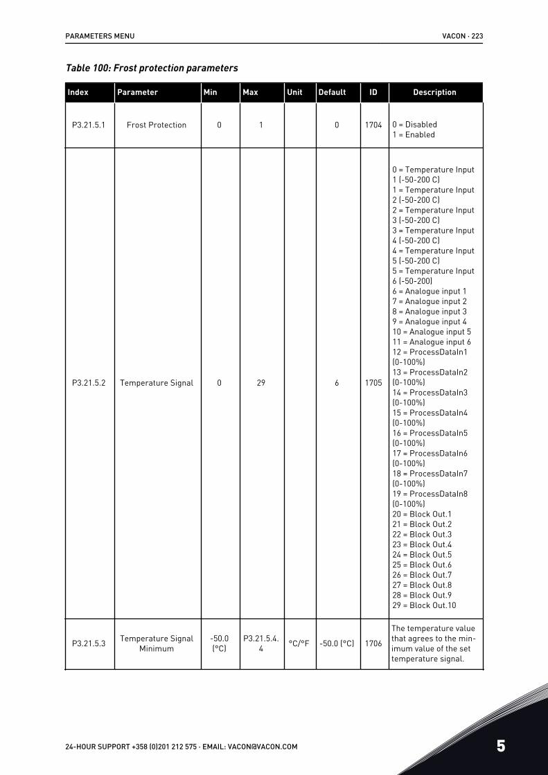
Table 100: Frost protection parameters
Index Parameter Min Max Unit Default ID Description
P3.21.5.1 Frost Protection 0 1 0 1704 0 = Disabled1 = Enabled
P3.21.5.2 Temperature Signal 0 29 6 1705
0 = Temperature Input1 (-50-200 C)1 = Temperature Input2 (-50-200 C)2 = Temperature Input3 (-50-200 C)3 = Temperature Input4 (-50-200 C)4 = Temperature Input5 (-50-200 C)5 = Temperature Input6 (-50-200)6 = Analogue input 17 = Analogue input 28 = Analogue input 39 = Analogue input 410 = Analogue input 511 = Analogue input 612 = ProcessDataIn1(0-100%)13 = ProcessDataIn2(0-100%)14 = ProcessDataIn3(0-100%)15 = ProcessDataIn4(0-100%)16 = ProcessDataIn5(0-100%)17 = ProcessDataIn6(0-100%)18 = ProcessDataIn7(0-100%)19 = ProcessDataIn8(0-100%)20 = Block Out.121 = Block Out.222 = Block Out.323 = Block Out.424 = Block Out.525 = Block Out.626 = Block Out.727 = Block Out.828 = Block Out.929 = Block Out.10
P3.21.5.3 Temperature SignalMinimum
-50.0(°C)
P3.21.5.4.4 °C/°F -50.0 (°C) 1706
The temperature valuethat agrees to the min-imum value of the settemperature signal.
PARAMETERS MENU VACON · 223
24-HOUR SUPPORT +358 (0)201 212 575 · EMAIL: [email protected] 5

Table 100: Frost protection parameters
Index Parameter Min Max Unit Default ID Description
P3.21.5.4 Temperature SignalMaximum
P3.21.5.3 200.0 (°C) °C/°F 200.0 (°C) 1707
The temperature valuethat agrees to the max-imum value of the settemperature signal.
P3.21.5.5 Frost ProtectionTemperature Limit
P3.21.5.3 P3.21.5.4 °C/°F 5.00 (°C) 1708
The temperature limitbelow which the Frostprotection functionactivates.
P3.21.5.6 Frost Protection Fre-quency 0.0 P3.3.1.2 Hz 10.0 1710
The constant frequencyreference that is usedwhen the Frost protec-tion function activates.
V3.21.5.7 Frost TemperatureMonitoring Varies Varies °C/°F 1711
The monitoring valuefor the measured tem-perature signal in theFrost protection func-tion. Scaling value: 0.1.
VACON · 224 PARAMETERS MENU
5 TEL. +358 (0)201 2121 · FAX +358 (0)201 212 205

6 DIAGNOSTICS MENU6.1 ACTIVE FAULTS
When there is a fault or many faults, the display shows the name of the fault and blinks. PushOK to go back to the Diagnostics menu. The submenu Active faults shows the number offaults. To see the fault-time data, make a selection of a fault and push OK.
The fault stays active until you reset it. There are 4 ways to reset a fault.
• Push the Reset button for 2 s.• Go into the submenu Reset faults and use the parameter Reset Faults.• Give a reset signal in the I/O terminal.• Give a reset signal with the fieldbus.
The Active faults submenu can keep a storage of maximum 10 faults. The submenu showsthe faults in the sequence in which they occurred.
6.2 RESET FAULTS
In this menu, you can reset faults. See instructions in Chapter 11.1 A fault comes into view.
CAUTION!
Before you reset the fault, remove the external Control signal to prevent that yourestart the drive accidentally.
6.3 FAULT HISTORY
You can see 40 faults in the Fault history.
To see the details of a fault, go into Fault history, find the fault and push OK.
6.4 TOTAL COUNTERS
If you read a counter value through fieldbus, see 10.16 Counters.
DIAGNOSTICS MENU VACON · 225
24-HOUR SUPPORT +358 (0)201 212 575 · EMAIL: [email protected] 6

Table 101: The total counter parameters in the diagnostics menu
Index Parameter Min Max Unit Default ID Description
V4.4.1
Energy Counter Varies 2291
The quantity of energyfrom the mains. Youcannot reset the coun-ter.In the text display: thehighest energy unitthat the display showsis MW. If the countedenergy becomes morethan 999.9 MW, no unitshows on the display.
V4.4.3 Operating Time(graphical keypad)
a dhh:min 2298 The operating time of
the control unit.
V4.4.4 Operating Time (textkeypad) a
The operating time ofthe control unit in totalyears.
V4.4.5 Operating Time (textkeypad) d
The operating time ofthe control unit in totaldays.
V4.4.6 Operating Time (textkeypad)
hh:min:ss
The operating time ofthe control unit inhours, minutes andseconds.
V4.4.7 Run Time (graphicalkeypad)
a dhh:min 2293 The motor run time.
V4.4.8 Run Time (text key-pad) a The motor run time in
total years.
V4.4.9 Run Time (text key-pad) d The motor run time in
total days.
V4.4.10 Run Time (text key-pad)
hh:min:ss
The motor run time inhours, minutes andseconds.
V4.4.11 Power On Time(graphical keypad)
a dhh:min 2294
The quantity of timethat the power unit ispowered on. You can-not reset the counter.
V4.4.12 Power On Time (textkeypad) a The power on time in
total years.
V4.4.13 Power On Time (textkeypad) d The power on time in
total days.
VACON · 226 DIAGNOSTICS MENU
6 TEL. +358 (0)201 2121 · FAX +358 (0)201 212 205

Table 101: The total counter parameters in the diagnostics menu
Index Parameter Min Max Unit Default ID Description
V4.4.14 Power On Time (textkeypad)
hh:min:ss
The power on time inhours, minutes andseconds.
V4.4.15 Start CommandCounter 2295
The number of timesthat the power unit isstarted.
6.5 TRIP COUNTERS
If you read a counter value through fieldbus, see Chapter 10.16 Counters.
Table 102: The trip counter parameters in the diagnostics menu
Index Parameter Min Max Unit Default ID Description
P4.5.1 Energy Trip Counter Varies 2296
You can reset thiscounter. In the text dis-play: the highestenergy unit that thedisplay shows is MW. Ifthe counted energybecomes more than999.9 MW, no unitshows on the display.
Resetting thecounter• In the text display:
Push the OK but-ton for 4 s.
• In the graphicaldisplay: Push OK.A Reset counterpage shows. PushOK again.
P4.5.3 Operating Time(graphical keypad)
a dhh:min 2299
You can reset thiscounter. See instruc-tions in P4.5.1 above.
P4.5.4 Operating Time (textkeypad) a The operating time in
total years.
P4.5.5 Operating Time (textkeypad) d The operating time in
total days.
P4.5.6 Operating Time (textkeypad)
hh:min:ss
The operating time inhours, minutes andseconds.
DIAGNOSTICS MENU VACON · 227
24-HOUR SUPPORT +358 (0)201 212 575 · EMAIL: [email protected] 6

6.6 SOFTWARE INFO
Table 103: The software info parameters in the diagnostics menu
Index Parameter Min Max Unit Default ID Description
V4.6.1 Software Package(graphical keypad)
The code for the soft-ware identification
V4.6.2 Software Package ID(text keypad)
V4.6.3 Software PackageVersion (text keypad)
V4.6.4 System Load 0 100 % 2300 The load on the controlunit CPU
V4.6.5 Application Name(graphical keypad)
The name of the appli-cation
V4.6.6 Application ID The code of the appli-cation
V4.6.7 Application Version
VACON · 228 DIAGNOSTICS MENU
6 TEL. +358 (0)201 2121 · FAX +358 (0)201 212 205

7 I/O AND HARDWARE MENUIn this menu, there are different settings that are related to the options. The values in thismenu are raw values, that is, they are not scaled by the application.
7.1 BASIC I/O
In the Basic I/O menu, you can monitor the statuses of the inputs and the outputs.
I/O AND HARDWARE MENU VACON · 229
24-HOUR SUPPORT +358 (0)201 212 575 · EMAIL: [email protected] 7

Table 104: The basic I/O parameters in the I/O and Hardware menu
Index Parameter Min Max Unit Default ID Description
V5.1.1 Digital Input 1 0 1 0 Status of the digitalinput signal
V5.1.2 Digital Input 2 0 1 0 Status of the digitalinput signal
V5.1.3 Digital Input 3 0 1 0 Status of the digitalinput signal
V5.1.4 Digital Input 4 0 1 0 Status of the digitalinput signal
V5.1.5 Digital Input 5 0 1 0 Status of the digitalinput signal
V5.1.6 Digital Input 6 0 1 0 Status of the digitalinput signal
V5.1.7 Analogue Input 1Mode 1 3 3
Shows the mode that isset for the analogueinput signal. The selec-tion is made with a DIPswitch on the controlboard.
1 = 0...20mA3 = 0...10V
V5.1.8 Analogue Input 1 0 100 % 0.00 Status of the analogueinput signal
V5.1.9 Analogue Input 2Mode 1 3 3
Shows the mode that isset for the analogueinput signal. The selec-tion is made with a DIPswitch on the controlboard.
1 = 0...20mA3 = 0...10V
V5.1.10 Analogue Input 2 0 100 % 0.00 Status of the analogueinput signal
VACON · 230 I/O AND HARDWARE MENU
7 TEL. +358 (0)201 2121 · FAX +358 (0)201 212 205

Table 104: The basic I/O parameters in the I/O and Hardware menu
Index Parameter Min Max Unit Default ID Description
V5.1.11 Analogue Output 1Mode 1 3 1
Shows the mode that isset for the analogueinput signal. The selec-tion is made with a DIPswitch on the controlboard.
1 = 0...20mA3 = 0...10V
V5.1.12 Analogue Output 1 0 100 % 0.00 Status of the analogueoutput signal
V5.1.13 Relay Output 1 0 1 0 Status of the relay out-put signal
V5.1.14 Relay Output 2 0 1 0 Status of the relay out-put signal
V5.1.15 Relay Output 3 0 1 0 Status of the relay out-put signal
7.2 OPTION BOARD SLOTS
The parameters in this menu are different for all the option boards. You see the parametersof the option board that you installed. If there is no option board in the slots C, D or E, you donot see parameters. See more about the location of the slots in Chapter 10.5.1 Programming of digital and analogue inputs.
When you remove an option board, the fault code 39 and the fault name Device removed showon the display. See Chapter 11.3 Fault codes.
Table 105: Option board related parameters
Menu Function Description
Slot CSettings The settings that are related to the option board
Monitoring Monitor the data that is related to the option board
Slot DSettings The settings that are related to the option board
Monitoring Monitor the data that is related to the option board
Slot ESettings The settings that are related to the option board
Monitoring Monitor the data that is related to the option board
I/O AND HARDWARE MENU VACON · 231
24-HOUR SUPPORT +358 (0)201 212 575 · EMAIL: [email protected] 7

7.3 REAL TIME CLOCK
Table 106: The real time clock parameters in the I/O and Hardware menu
Index Parameter Min Max Unit Default ID Description
V5.5.1 Battery State 1 3 2205
Status of the battery.
1 = Not installed2 = Installed3 = Replace the battery
P5.5.2 Time hh:mm:ss 2201 The current time of the
day
P5.5.3 Date dd.mm. 2202 The current date
P5.5.4 Year yyyy 2203 The current year
P5.5.5 Daylight Saving 1 4 1 2204
The daylight savingrule
1 = Off2 = EU: starts on thelast Sunday in March,ends on the last Sun-day in October3 = US: starts on the2nd Sunday in March,ends on the 1st Sundayin November4 = Russia (permanent)
7.4 POWER UNIT SETTINGS
In this menu, you can change the settings of the fan and the sine filter.
The fan operates in the optimised or the always on mode. In the optimised mode, the internallogic of the drive receives data about the temperature and controls the fan speed. After thedrive goes into the Ready state, the fan stops in 5 minutes. In the always on mode, the fanoperates in full speed, and does not stop.
The sine filter keeps the overmodulation depth in limits and does not let the thermalmanagement functions decrease the switching frequency.
VACON · 232 I/O AND HARDWARE MENU
7 TEL. +358 (0)201 2121 · FAX +358 (0)201 212 205

Table 107: Power unit settings
Index Parameter Min Max Unit Default ID Description
P5.6.1.1 Fan Control Mode 0 1 1 2377 0 = Always on1 = Optimised
P5.6.4.1 Sine Filter 0 1 0 0 = Not used1 = In use
7.5 KEYPAD
Table 108: The keypad parameters in the I/O and Hardware menu
Index Parameter Min Max Unit Default ID Description
P5.7.1 Timeout Time 0 60 min 0 *
The time after whichthe display goes backto the page that is setwith parameter P5.7.2.
0 = Not used
P5.7.2 Default Page 0 4 0 *
The page that the dis-play shows when thedrive is powered up, orwhen the time that isset with P5.7.1 goes. Ifthe value is set to 0,the display shows thelast page that itshowed.
0 = None1 = Enter menu index2 = Main menu3 = Control page4 = Multimonitor
P5.7.3 Menu IndexSet a page to be themenu index. (Theselection 1 in P5.7.2.)
P5.7.4 Contrast ** 30 70 % 50 Set the contrast of thedisplay (30-70%).
P5.7.5 Backlight Time 0 60 min 5
Set the time afterwhich the backlight ofthe display goes out(0-60 min). If the valueis set to 0, the back-light is always on.
I/O AND HARDWARE MENU VACON · 233
24-HOUR SUPPORT +358 (0)201 212 575 · EMAIL: [email protected] 7

* = The selection of the application with parameter P1.2 Application gives the default value.See the default values in 12.1 The default values of parameters in the different applications.
** Only available with the graphical keypad.
7.6 FIELDBUS
In the I/O and Hardware menu, there are the parameters that are related to different fieldbusboards. You can find the instructions on how to use these parameters in the related fieldbusmanual.
VACON · 234 I/O AND HARDWARE MENU
7 TEL. +358 (0)201 2121 · FAX +358 (0)201 212 205

8 USER SETTINGS, FAVOURITES AND USER LEVELMENUS
8.1 USER SETTINGS
8.1.1 USER SETTINGS
Table 109: General settings in the user settings menu
Index Parameter Min Max Unit Default ID Description
P6.1 Language Selections Varies Varies Varies 802The selection is differ-ent in all the languagepackages.
P6.2 Application Selection 801 Select the application.
M6.5 Parameter Backup See Table 110 The parameter backup parameters in the user settings menu.
M6.6 Parameter Compare
P6.7 Drive NameGive a name to thedrive if you think that itis necessary.
USER SETTINGS, FAVOURITES AND USER LEVEL MENUS VACON · 235
24-HOUR SUPPORT +358 (0)201 212 575 · EMAIL: [email protected] 8

8.1.2 PARAMETER BACKUP
Table 110: The parameter backup parameters in the user settings menu
Index Parameter Min Max Unit Default ID Description
P6.5.1 Restore FactoryDefaults 831
Restores the defaultparameter values andstarts the Startup wiz-ard.
P6.5.2 Save to Keypad* 0 1 0
Saves the parametervalues to the controlpanel, for example tocopy them to anotherdrive.
0 = No1 = Yes
P6.5.3 Restore from Keypad*
Loads the parametervalues from the controlpanel to the drive.
B6.5.4 Save to Set 1
Keeps a customisedparameter set (that is,all the parametersincluded in the applica-tion).
B6.5.5 Restore from Set 1Loads the customisedparameter set to thedrive.
B6.5.6 Save to Set 2
Keeps another custom-ised parameter set(that is, all the parame-ters included in theapplication).
B6.5.7 Restore from Set 2Loads the customisedparameter set 2 to thedrive.
* Only available with the graphical display.
8.2 FAVOURITES
NOTE!
This menu is not available in the text display.If you use the same items frequently, you can add them into Favourites. You can collect a setof parameters or monitoring signals from all the keypad menus. It is not necessary to find
VACON · 236 USER SETTINGS, FAVOURITES AND USER LEVEL MENUS
8 TEL. +358 (0)201 2121 · FAX +358 (0)201 212 205

them in the menu structure one by one. As an alternative, add them into the Favouritesfolder where it is easy to find them.
ADDING AN ITEM TO THE FAVOURITES
1 Find the item that you want to add to Favourites.Push the OK button. STOP READY I/O
Basic Settings
Motor Nom Freq
Motor Nom Speed
Motor Nom Voltg230.00 V
50.00 Hz
1430 rpm
2 Make a selection of Add to favourites and push theOK button. STOP READY I/O
Motor Nom Freq
Edit
Help
Add to favourites
3 The steps are now completed. To continue, read theinstructions on the display. STOP READY I/O
Motor Nom Freq
was added tofavourites. Press OKto continue.
REMOVING AN ITEM FROM THE FAVOURITES
1 Go to the Favourites.
USER SETTINGS, FAVOURITES AND USER LEVEL MENUS VACON · 237
24-HOUR SUPPORT +358 (0)201 212 575 · EMAIL: [email protected] 8

2 Find the item that you want to remove. Push the OKbutton. STOP READY I/O
Favourites
Motor Nom Freq50.00 Hz
3 Make a selection of Rem from favourites.STOP READY I/O
Motor Nom Freq
Rem from favourites
Help
Monitor
4 To remove the item, push the OK button again.
8.3 USER LEVELS
Use the User level parameters to keep the personnel who are not approved from makingchanges in the parameters. You can also prevent accidental changes in the parameters.
When you make a selection of a user level, the user cannot see all the parameters on thedisplay of the control panel.
VACON · 238 USER SETTINGS, FAVOURITES AND USER LEVEL MENUS
8 TEL. +358 (0)201 2121 · FAX +358 (0)201 212 205

Table 111: The user level parameters
Index Parameter Min Max Unit Default ID Description
P8.1 User Level 1 3 1 1194
1 = Normal. All themenus are visible inthe main menu.2 = Monitoring. Onlythe monitoring anduser level menus arevisible in the mainmenu.3 = Favourites. Onlythe favourites and userlevel menus are visiblein the main menu.
P8.2 Access Code 0 99999 0 2362
If you set the value tobe to other than 0before you go to Moni-toring from, for exam-ple, Normal, you haveto give the access codewhen you go back toNormal. This preventspersonnel who are notapproved from makingchanges in the param-eters on the controlpanel.
CAUTION!
Do not lose the access code. If the access code is lost, contact your nearest servicecenter or partner.
CHANGING THE ACCESS CODE OF THE USER LEVELS
1 Go to the User levels.2 Go to the item Access code and push the arrow
button Right. STOP READY ALARM Keypad
Main Menu
NormalUser level
00000Access code
P8.2ID:2362
USER SETTINGS, FAVOURITES AND USER LEVEL MENUS VACON · 239
24-HOUR SUPPORT +358 (0)201 212 575 · EMAIL: [email protected] 8

3 To change the digits of the access code, use all thearrow buttons. STOP READY ALARM I/O
ID:2362 P8.2Access code
Min:0Max:9
00000
4 Accept the change with the OK button.
VACON · 240 USER SETTINGS, FAVOURITES AND USER LEVEL MENUS
8 TEL. +358 (0)201 2121 · FAX +358 (0)201 212 205

9 MONITORING VALUE DESCRIPTIONSThis chapter gives you information on some of the monitoring values. The basic descriptionsof all monitoring values are in 4 Monitoring menu.
V2.3.17 U PHASE CURRENT (ID 39)
V2.3.18 V PHASE CURRENT (ID 40)
V2.3.19 W PHASE CURRENT (ID 41)
The monitoring values show the measured current of the motor in phases U, V and W (1 sfilter).
V2.3.20 DRIVE INPUT POWER (ID 10)
The monitoring value shows the estimation of the drive input power in kW.
V2.10.6 COMMUNICATION STATUS (ID1629)
The status of the drive-to-drive communication when the system is the Multipump(multidrive) system.
0 = Not used (Multipump multidrive function not used)10 = Fatal communication errors occurred (or no communication)11 = Errors occurred (sending of data )12 = Errors occurred (receiving of data)20 = Communication operational, no errors occurred30 = Status unknown
NOTE!
If the statuses 11 or 12 occur, the communication in one of the drives in theMultipump system is not correct. The communication between the other drives iscorrect.
V2.10.7 PUMP 1 RUNNING TIME (ID 1620)
The monitoring value shows the hours that pump 1 operates in the Multipump single drivesystem. In the Multipump multidrive system the monitoring value shows the hours that thispump operates. You can see the hours that the pump operates with a resolution of 0.1 h.
V2.10.8 PUMP 2 RUNNING TIME (ID 1621)
V2.10.10 PUMP 4 RUNNING TIME (ID 1623)
V2.10.10 PUMP 4 RUNNING TIME (ID 1623)
MONITORING VALUE DESCRIPTIONS VACON · 241
24-HOUR SUPPORT +358 (0)201 212 575 · EMAIL: [email protected] 9

V2.10.11 PUMP 5 RUNNING TIME (ID 1624)
V2.10.12 PUMP 6 RUNNING TIME (ID 1625)
V2.10.13 PUMP 7 RUNNING TIME (ID 1626)
V2.10.14 PUMP 8 RUNNING TIME (ID 1627)
The monitoring values show the hours that pumps 2-8 operate in the Multipump single drivesystem. In the Multipump multidrive system the function is not available. See the monitoringvalue V2.10.7 in Table 23 Multipump monitoring. You can see the hours that the pumps operatewith a resolution of 0.1 h.
VACON · 242 MONITORING VALUE DESCRIPTIONS
9 TEL. +358 (0)201 2121 · FAX +358 (0)201 212 205

10 PARAMETER DESCRIPTIONSIn this chapter, you can find data on the most special parameters of the application. For mostparameters of the Vacon 100 application, a basic description is sufficient. You can find thesebasic descriptions in the parameter tables of Chapter 5 Parameters menu. If other data isnecessary, your distributor will help you.
P1.2 APPLICATION (ID212)
In P1.2 you can make a selection of an application that is best for your process. Theapplications include preset application configurations, that is, sets of predefined parameters.The selection of the application makes the commissioning of the drive easy and reduces themanual work with the parameters.
These configurations are loaded to the drive when the value of parameter P1.2 Applicationchanges. You can change the value of this parameter when you make the startup or thecommissioning of the drive.
If you use the control panel to change this parameter, an application wizard starts and helpsyou to set the basic parameters related to the application. The wizard does not start, if youuse the PC tool to change this parameter. You can find information about the applicationwizards in Chapter 2 Wizards.
These applications are available:
0 = Standard1 = HVAC2 = PID control3 = Multipump (single drive)4 = Multipump (multidrive)
NOTE!
When you change the application, the contents of the Quick Setup menu change.
10.1 MOTOR SETTINGS
P3.1.1.2 MOTOR NOMINAL FREQUENCY (ID 111)
When this parameter changes, parameters P3.1.4.2 Field Weakening Point Frequency andP3.1.4.3 Voltage at Field Weakening Point start automatically. The 2 parameters havedifferent values for each motor type. See the tables in P3.1.2.2 Motor Type (ID 650).
P3.1.2.2 MOTOR TYPE (ID 650)
In this parameter, you can set the type of motor in your process.
PARAMETER DESCRIPTIONS VACON · 243
24-HOUR SUPPORT +358 (0)201 212 575 · EMAIL: [email protected] 10

Selectionnumber Selection name Description
0 Induction motor (IM) Make this selection if you use an induction motor.
1 Permanent Magnet Motor (PM) Make this selection if you use a permanent magnet motor.
When you change the value of parameter P3.1.2.2 Motor Type, the values of parametersP3.1.4.2 Field Weakening Point Frequency and P3.1.4.3 Voltage at Field Weakening Pointchange automatically, as the table below shows. The 2 parameters have different values foreach motor type.
Parameter Induction motor (IM) Permanent magnet motor (PM)
P3.1.4.2 (Field Weakening PointFrequency) Motor nominal frequency Internally calculated
P3.1.4.3 (Voltage at Field Weaken-ing Point) 100.0% Internally calculated
P3.1.2.4 IDENTIFICATION (ID 631)
The identification run calculates or measures the motor parameters that are necessary for agood control of the motor and speed.
The identification run helps you to adjust the motor-specific and the drive-specificparameters. It is a tool for the commissioning and the servicing of the drive. The goal is tofind the parameter values that are optimal for the operation of the drive.
NOTE!
Before you do the identification run, you have to set the motor nameplateparameters.
Selectionnumber Selection name Description
0 No action No identification requested.
1 Identification at standstill
The drive operates without speed when you do the identifica-tion run for the motor parameters. The motor receives cur-rent and voltage, but the frequency is zero. The U/f ratio andstart magnetisation parameters are identified.
2 Identification with motor rotat-ing
The drive operates with speed when you do the identificationrun for the motor parameters. The U/f ratio, the magnetisa-tion current and start magnetisation parameters are identi-fied.
To get accurate results, do this identification run with noload on the motor shaft.
VACON · 244 PARAMETER DESCRIPTIONS
10 TEL. +358 (0)201 2121 · FAX +358 (0)201 212 205

To activate the Identification function, set the parameter P3.1.2.4 and give a start command.You have to give the start command in 20 s. If there is no start command in that time, theidentification run does not start. The parameter P3.1.2.4 is reset to the default value and anidentification alarm shows.
To stop the identification run before it is completed, give a stop command. This resets theparameter to the default value. If the identification run is not completed, an identificationalarm shows.
NOTE!
To start the drive after the identification, a new start command is necessary.
P3.1.2.6 MOTOR SWITCH (ID 653)
You can use the Motor switch function, if the cable that connects the motor and the drive hasa motor switch. The operation of the motor switch makes sure that the motor is isolatedfrom the voltage source and does not start during the servicing.
To activate the function, set the parameter P3.1.2.6 to the value Enabled. The drive stopsautomatically when the motor switch is opened, and the drive starts automatically when themotor switch is closed. The drive does not trip when you use the Motor switch function.
0
Mains
1
B
A
Fig. 36: The motor switch between the drive and the motorA. The motor switch B. Mains
P3.1.2.10 OVERVOLTAGE CONTROL (ID 607)
See the description in P3.1.2.11 Undervoltage Control.
P3.1.2.11 UNDERVOLTAGE CONTROL (ID 608)
With parameters P3.1.2.10 Overvoltage Control and P3.1.2.11 Undervoltage Control, you canset the undervoltage controller and the overvoltage controller out of operation.
The function is necessary when
PARAMETER DESCRIPTIONS VACON · 245
24-HOUR SUPPORT +358 (0)201 212 575 · EMAIL: [email protected] 10

• the supply voltage changes, for example, between -15% and +10%, and• the process you control does not have the tolerance for the changes that the
undervoltage controller and the overvoltage controller make to the output frequency ofthe drive.
The undervoltage controller decreases the output frequency of the drive• to get energy from the motor to keep the DC link voltage at a minimum level when the
voltage is near the lowest permitted limit, and• to make sure that the drive does not trip because of an undervoltage fault.
The overvoltage controller increases the output frequency of the drive• to keep the DC link voltage in the permitted limits, and• to make sure that the drive does not trip because of an overvoltage fault.
NOTE!
The drive can trip when the overvoltage and undervoltage controllers are disabled.
P3.1.2.13 STATOR VOLTAGE ADJUST (ID 659)
NOTE!
The identification run sets a value for this parameter automatically. Werecommend that you make the identification run, if it is possible. You can make theidentification run with the parameter P3.1.2.4.
It is possible to use this parameter only when the parameter P3.1.2.2 Motor Type has thevalue PM motor. If you set induction motor as the motor type, the value is automatically set to100%, and you cannot change the value.
When you change the value of P3.1.2.2 (Motor type) to PM Motor, the parameters P3.1.4.2(Field Weakening Point Frequency) and P3.1.4.3 (Voltage at Field Weakening Point) willincrease automatically to be equal with output voltage of the drive. The set U/f ratio does notchange. This is done to prevent the operation of the PM motor in the field weakening area.The nominal voltage of the PM motor is much lower than the full output voltage of the drive.
The nominal voltage of the PM motor agrees to the back-EMF voltage of the motor atnominal frequency. But in a different motor manufacturer, it can be equal to, for example,the stator voltage at nominal load.
Stator Voltage Adjust helps you to adjust the U/f curve of the drive near the back-EMF curve.It is not necessary to change the values of many U/f curve parameters.
The parameter P3.1.2.13 gives the output voltage of the drive in percentage of the nominalvoltage of the motor at the nominal frequency of the motor. Adjust the U/f curve of the driveabove the back-EMF curve of the motor. The motor current increases the more the U/f curveis different from the back-EMF curve.
VACON · 246 PARAMETER DESCRIPTIONS
10 TEL. +358 (0)201 2121 · FAX +358 (0)201 212 205
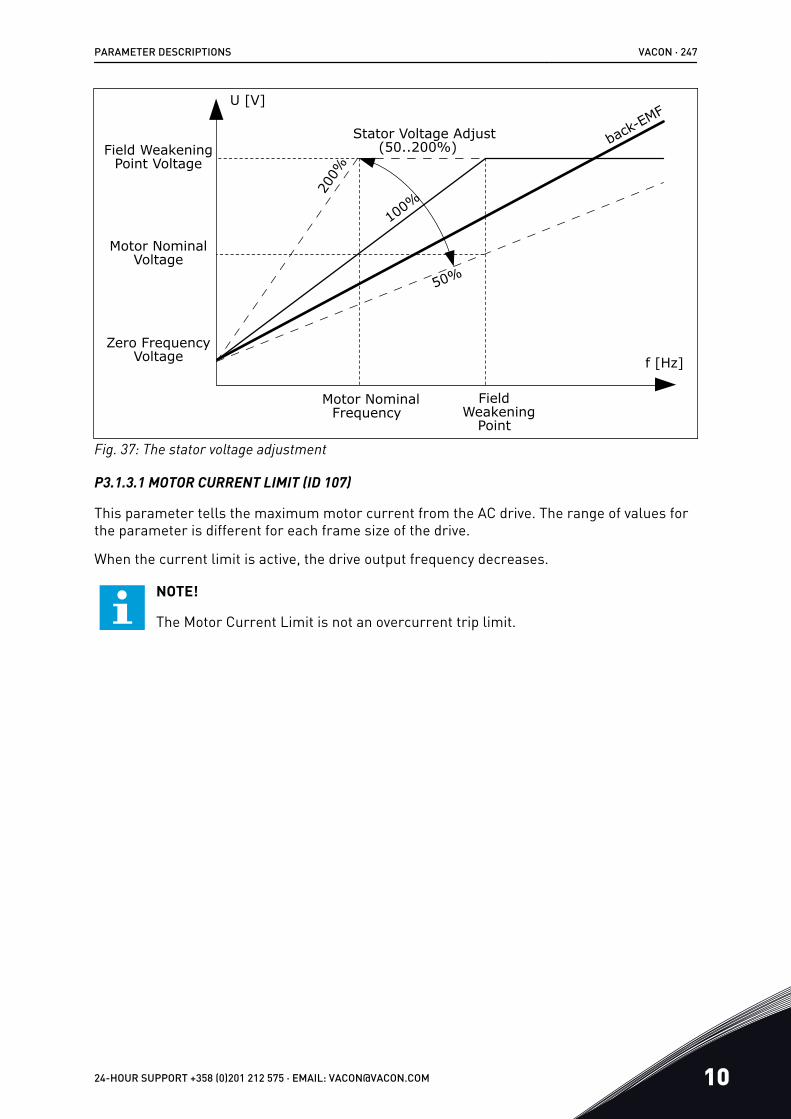
FieldWeakening
Point
Field WeakeningPoint Voltage
Motor NominalVoltage
Motor NominalFrequency
Stator Voltage Adjust back-EMF
Zero FrequencyVoltage
(50..200%)
200%
100%
50%
f [Hz]
U [V]
Fig. 37: The stator voltage adjustment
P3.1.3.1 MOTOR CURRENT LIMIT (ID 107)
This parameter tells the maximum motor current from the AC drive. The range of values forthe parameter is different for each frame size of the drive.
When the current limit is active, the drive output frequency decreases.
NOTE!
The Motor Current Limit is not an overcurrent trip limit.
PARAMETER DESCRIPTIONS VACON · 247
24-HOUR SUPPORT +358 (0)201 212 575 · EMAIL: [email protected] 10

P3.1.4.1 U/F RATIO (ID 108)
Selectionnumber Selection name Description
0 Linear
The voltage of the motor changes linearly as a function of theoutput frequency. The voltage changes from the value ofP3.1.4.6 (Zero Frequency Voltage) to the value of P3.1.4.3(Voltage at Field Weakening Point) at at a frequency set inP3.1.4.2 (Field Weakening Point Frequency). Use this defaultsetting if a different setting is not necessary.
1 Squared
The voltage of the motor changes from the value of P3.1.4.6(Zero Frequency Voltage) to the value of P3.1.4.2 (FieldWeakening Point Frequency) at a squared curve. The motoroperates undermagnetised below the field weakening pointand produces less torque. You can use the squared U/f ratioin applications where the torque demand is in relation to thesquare of the speed, for example in centrifugal fans andpumps.
2 Programmable
It is possible to program the U/f curve with 3 different points:the zero frequency voltage (P1), the midpoint voltage/frequency (P2), and the field weakening point (P3). You canuse the programmable U/f curve at low frequencies if it isnecessary to have more torque. You can find the optimal set-tings automatically with an identification run (P3.1.2.4).
Un
ID603
ID602
Default: Nominalvoltage of the motor
Linear
Squared
Fieldweakeningpoint
Default:Nominal frequencyof the motor
U[V]
f[Hz]
Fig. 38: Linear and squared change of the motor voltage
VACON · 248 PARAMETER DESCRIPTIONS
10 TEL. +358 (0)201 2121 · FAX +358 (0)201 212 205

P1
P2
P3
ID604
ID605
ID606
Default: Nominalvoltage of the motor
Field weakening point
Default: Nominalfrequency of the motor
UnID603
ID602
U[V]
f[Hz]
Fig. 39: The programmable U/f curve
When the parameter Motor Type has the value PM motor (Permanent Magnet Motor), thisparameter is automatically set to the value Linear.
When the parameter Motor Type has the value Induction Motor, and when this parameter ischanged, these parameters are set to their default values.• P3.1.4.2 Field Weakening Point Frequency• P3.1.4.3 Voltage at Field Weakening Point• P3.1.4.4 U/f Midpoint Frequency• P3.1.4.5 U/f Midpoint Voltage• P3.1.4.6 Zero Frequency Voltage
P3.1.4.3 VOLTAGE AT FIELD WEAKENING POINT (ID 603)
Above the frequency at the field weakening point, the output voltage stays at the setmaximum value. Below the frequency at the field weakening point, the U/f curve parameterscontrol the output voltage. See the U/f parameters P3.1.4.1, P3.1.4.4 and P3.1.4.5.
When you set the parameters P3.1.1.1 (Motor nominal voltage) and P3.1.1.2 (Motor nominalfrequency), the parameters P3.1.4.2 and P3.1.4.3 automatically receive related values. Tohave different values for P3.1.4.2 and P3.1.4.3, change these parameters only after you setthe parameters P3.1.1.1 and P3.1.1.2.
P3.1.4.7 FLYING START OPTIONS (ID 1590)
The parameter Flying Start Options has a checkbox selection of values.
The bits can receive these values.• Search the shaft frequency only from the same direction as the frequency reference• Disable the AC scanning• Use the frequency reference for an initial guess• Disable the DC pulses
PARAMETER DESCRIPTIONS VACON · 249
24-HOUR SUPPORT +358 (0)201 212 575 · EMAIL: [email protected] 10
The bit B0 controls the search direction. When you set the bit to 0, the shaft frequency issearched in 2 directions, the positive and the negative. When you set the bit to 1, the shaftfrequency is searched only in the frequency reference direction. This prevents the shaftmovements for the other direction.
The bit B1 controls the AC scanning that premagnetises the motor. In the AC scanning, thesystem sweeps the frequency from the maximum towards zero frequency. The AC scanningstops when an adaptation to the shaft frequency occurs. To disable the AC scanning, set thebit B1 to 1. If the value of Motor Type is permanent magnet motor, the AC scanning isdisabled automatically.
With the bit B5 you can disable the DC pulses. The primary function of the DC pulses is topremagnetise the motor and examine the rotation of the motor. If the DC pulses and the ACscanning are enabled, the slip frequency tells which procedure is applied. If the slipfrequency is less than 2 Hz, or the motor type is PM motor, the DC pulses are disabledautomatically.
10.1.1 P3.1.4.9 START BOOST (ID 109)Use this parameter with a process that has a high start torque because of friction.You can use the start boost only when you start the drive. The start boost is deactivated after10 seconds or when the output frequency of the drive is more than half of the frequency ofthe field weakening point.
The voltage to the motor changes in relation to the necessary torque. This makes the motorgive more torque at the start and when the motor operates at low frequencies.
The start boost has an effect with a linear U/f curve. You can get the best result when youhave done the identification run and activated the programmable U/f curve.
10.1.2 I/F START FUNCTIONWhen you have a PM motor, use the I/f Start function to start the motor with constant currentcontrol. You can receive the best effect with a high power motor. With a high power motor,the resistance is low and it is not easy to change the U/f curve.
The I/f Start function can also give a sufficient torque for the motor at startup.
VACON · 250 PARAMETER DESCRIPTIONS
10 TEL. +358 (0)201 2121 · FAX +358 (0)201 212 205

Motor Current
Time [s]I/f StartFrequency
I/f Start Current
Output Frequency
Fig. 40: The I/f start parameters
P3.1.4.12.1 I/F START (ID 534)
When you activate the I/f Start function, the drive starts to operate in the current controlmode. A constant current is led to the motor until the output frequency increases above thelevel that is set in P3.1.4.12.2. When the output frequency increases above I/f StartFrequency level, the operation mode changes back to the normal U/f control mode.
P3.1.4.12.2 I/F START FREQUENCY (ID 535)
When the output frequency of the drive is below the limit of this parameter, I/f Start functionactivates. When the output frequency is more than the limit, the drive operation modechanges back to the normal U/f control mode.
P3.1.4.12.3 I/F START CURRENT (ID 536)
With this parameter, you can set the current that is used when the I/f Start function isenabled.
10.2 START/STOP SETUP
The drive is started and stopped from a control place. Each control place has a differentparameter to select the source of the frequency reference. You must give the start and stopcommands in each control place.The local control place is always the keypad. With parameter P3.2.1 Remote Control Placeyou can select the remote control place (I/O or Fieldbus). The selected control place showson the status bar of the keypad.
PARAMETER DESCRIPTIONS VACON · 251
24-HOUR SUPPORT +358 (0)201 212 575 · EMAIL: [email protected] 10

I/O SELGIN 0IN 1
SELGIN 0IN 1
SELGIN 0IN 1
SELGIN 0IN 1
SELGIN 0IN 1
SELGIN 0IN 1
MUXKIN 0IN 1
P3.5.1.7 I/O B Ctrl Force
I/O
I/O A
P
VFIELDBUSV
KEYPADV
KEYPADV
PCC
I/O BV
P3.2.1 Remote Control Place
P P3.2.2 Local/Remote
FB CW.bit8 Force to FB Control
I/O P3.5.1.9Fieldbus Ctrl Force
FIELDBUSV
FIELDBUSV
FINAL CONTROL PLACE
V
PC Control ActivePC
P3.5.1.10 Keypad Control Force
Fig. 41: Control place
REMOTE CONTROL PLACE (I/O A)
Use the parameters P3.5.1.1 (Control signal 1 A), P3.5.1.2 (Control signal 2 A) and P3.5.1.3(Control signal 3 A) to make a selection of digital inputs. These digital inputs control thestart, stop and reverse commands. Then make a selection of a logic for these inputs withP3.2.6 I/O A Logic.
REMOTE CONTROL PLACE (I/O B)
Use the parameters P3.5.1.4 (Control signal 1 B), P3.5.1.5 (Control signal 2 B) and P3.5.1.6(Control signal 3 B) to make a selection of digital inputs. These digital inputs control thestart, stop and reverse commands. Then make a selection of a logic for these inputs withP3.2.7 I/O B Logic.
LOCAL CONTROL PLACE (KEYPAD)
The start and stop commands come from the keypad buttons. The direction of the rotation isset with parameter P3.3.1.9 Keypad direction.
REMOTE CONTROL PLACE (FIELDBUS)
Start, stop and reverse commands come from the fieldbus.
VACON · 252 PARAMETER DESCRIPTIONS
10 TEL. +358 (0)201 2121 · FAX +358 (0)201 212 205

P3.2.5 STOP FUNCTION (ID 506)
Selectionnumber Selection name Description
0 CoastingThe motor stops on its inertia. When the stop command isgiven, the control by the drive stops and the current from thedrive goes to 0.
1 Ramp After the stop command, the speed of the motor is decreasedto zero speed according to the deceleration parameters.
P3.2.6 I/O A START/STOP LOGIC (ID 300)
It is possible to control the start and stop of the drive with the digital signals in thisparameter.
The selections that include the word edge help you to prevent an accidental start.
An accidental start can occur, for example, in these conditions
• When you connect the power.• When the power is connected again after a power cut.• After you reset a fault.• After Run Enable stops the drive.• When you change the control place to I/O control.
Before you can start the motor, you must open the Start/Stop contact.
In all the examples of the next pages, the stop mode is coasting. CS = Control signal.
Selectionnumber Selection name Description
0 CS1 = ForwardCS2 = Backward
The functions activate when the contacts are closed.
PARAMETER DESCRIPTIONS VACON · 253
24-HOUR SUPPORT +358 (0)201 212 575 · EMAIL: [email protected] 10

t
Outputfrequency
FWD
REV
Ctrl signal 2
Ctrl signal 1
Run enable
Set frequency
Set frequency
0 Hz
Keypad stopbutton
Keypad startbutton
1 2 3 4 5 6 7 8 9 10 11 12 13
Fig. 42: I/O A Start/stop logic = 01. Control signal (CS) 1 activates and
causes the output frequency to increase.The motor operates forward.
2. CS2 activates, but it does not have aneffect on the output frequency, becausethe direction that is set first has thehighest priority.
3. CS1 becomes inactive and causes thedirection to start to change (FWD toREV), because CS2 is still active.
4. CS2 becomes inactive and the frequencythat is fed to the motor goes to 0.
5. CS2 activates again and causes themotor to accelerate (REV) to the setfrequency.
6. CS2 becomes inactive and the frequencyfed to the motor drops to 0.
7. CS1 activates and the motor accelerates(FWD) to the set frequency
8. The Run enable signal is set to OPEN,which causes the frequency to go to 0.Configure the Run enable signal withparameter P3.5.1.15.
9. The Run enable signal is set to CLOSED,which causes the frequency to increaseto the set frequency, because CS1 is stillactive.
10. The STOP button on the keypad ispushed, and the frequency that is fed tothe motor goes to 0. (This signal onlyworks if the value of P3.2.3 Keypad StopButton is Yes.)
11. The drive starts because the STARTbutton on the keypad was pushed.
12. The STOP button on the keypad ispushed again to stop the drive.
13. The attempt to start the drive with theSTART button is not successful, becauseCS1 is inactive.
VACON · 254 PARAMETER DESCRIPTIONS
10 TEL. +358 (0)201 2121 · FAX +358 (0)201 212 205

Selectionnumber Selection name Description
1 CS1 = Forward (edge)CS2 = Inverted stopCS3 = Backward (edge)
For a 3-wire control (pulse control)
Set frequency
0 Hz
Keypad stopbutton
Ctrl signal 3
t
Outputfrequency
FWD
REV
Ctrl signal 2
Ctrl signal 1
Run enable
Set frequency
1 2 3 4 5 6 7 98 10
Fig. 43: I/O A Start/stop logic = 11. Control signal (CS) 1 activates and
causes the output frequency to increase.The motor operates forward.
2. CS2 becomes inactive and causes thefrequency to go to 0.
3. CS1 activates and causes the outputfrequency to increase again. The motoroperates forward.
4. CS3 activates and causes the direction tostart to change (FWD to REV).
5. The Run enable signal is set to OPEN,which causes the frequency to go to 0.Configure the Run enable signal withparameter 3.5.1.15.
6. The start attempt with CS1 is notsuccessful, because the Run enablesignal is still OPEN.
7. CS1 activates and the motor accelerates(FWD) to the set frequency, because theRun enable signal was set to CLOSED.
8. The STOP button on the keypad ispushed, and the frequency that is fed tothe motor goes to 0. (This signal onlyworks if the value of P3.2.3 Keypad StopButton is Yes.)
9. CS3 activates and causes the motor tostart and to operate in the reversedirection.
10. CS2 becomes inactive and causes thefrequency to go to 0.
PARAMETER DESCRIPTIONS VACON · 255
24-HOUR SUPPORT +358 (0)201 212 575 · EMAIL: [email protected] 10

Selectionnumber Selection name Description
2 CS1 = Forward (edge)CS2 = Backward (edge)
Use this function to prevent an accidental start. Before youcan start the motor again, you must open the start/stop con-tact.
1 2 3 4 5 6 7 8 9 10 11 12
t
Outputfrequency
FWD
REV
Ctrl signal 2
Ctrl signal 1
Run enable
Set frequency
Set frequency
0 Hz
Keypad stop button
Fig. 44: I/O A Start/stop logic = 21. Control signal (CS) 1 activates and
causes the output frequency to increase.The motor operates forward.
2. CS2 activates, but it does not have aneffect on the output frequency, becausethe direction that is set first has thehighest priority.
3. CS1 is becomes inactive and causes thedirection to start to change (FWD toREV), because CS2 is still active.
4. CS2 becomes inactive and the frequencythat is fed to the motor goes to 0.
5. CS2 activates again and causes themotor to accelerate (REV) to the setfrequency.
6. CS2 becomes inactive and the frequencythat is fed to the motor goes to 0.
7. CS1 activates and the motor accelerates(FWD) to the set frequency.
8. The Run enable signal is set to OPEN,which causes the frequency to go to 0.Configure the Run enable signal withparameter P3.5.1.15.
9. The Run enable signal is set to CLOSED,which does not have an effect, because arising edge is necessary for the start,even if CS1 is active.
10. The STOP button on the keypad ispushed and the frequency that is fed tothe motor goes to 0. (This signal onlyworks if the value of P3.2.3 Keypad StopButton is Yes.)
11. CS1 is opened and closed again, whichcauses the motor to start.
12. CS1 becomes inactive and the frequencythat is fed to the motor goes to 0.
VACON · 256 PARAMETER DESCRIPTIONS
10 TEL. +358 (0)201 2121 · FAX +358 (0)201 212 205

Selectionnumber Selection name Description
3 CS1 = StartCS2 = Reverse
1 2 3 4 6 7 8 9 10 11 12
5
t
Outputfrequency
FWD
REV
Ctrl signal 2
Ctrl signal 1
Run enable
Set frequency
Set frequency
0 Hz
Keypad stop button
Keypad start button
Fig. 45: I/O A Start/stop logic = 31. Control signal (CS) 1 activates and
causes the output frequency to increase.The motor operates forward.
2. CS2 activates and causes the direction tostart to change (FWD to REV).
3. CS2 becomes inactive, which causes thedirection to start to change (REV toFWD), because CS1 is still active.
4. CS1 becomes inactive and the frequencygoes to 0.
5. CS2 activates, but the motor does notstart because CS1 is inactive.
6. CS1 activates and causes the outputfrequency to increase again. The motoroperates forward because CS2 isinactive.
7. The Run enable signal is set to OPEN,which causes the frequency to go to 0.Configure the Run enable signal withparameter P3.5.1.15.
8. The Run enable signal is set to CLOSED,which causes the frequency to increaseto the set frequency, because CS1 is stillactive.
9. The STOP button on the keypad ispushed and the frequency that is fed tothe motor goes to 0. (This signal onlyworks if the value of P3.2.3 Keypad StopButton is Yes.)
10. The drive starts because the STARTbutton on the keypad was pushed.
11. The drive is stopped again with the STOPbutton on the keypad.
PARAMETER DESCRIPTIONS VACON · 257
24-HOUR SUPPORT +358 (0)201 212 575 · EMAIL: [email protected] 10

12. The attempt to start the drive with theSTART button is not successful, becauseCS1 is inactive.
Selectionnumber Selection name Description
4 CS1 = Start (edge)CS2 = Reverse
Use this function to prevent an accidental start. Before youcan start the motor again, you must open the start/stop con-tact.
1 2 3 4 6 7 8 9 10 11
5
t
Outputfrequency
FWD
REV
Ctrl signal 2
Ctrl signal 1
Run enable
Set frequency
Set frequency
0 Hz
Keypad stop button
Fig. 46: I/O A Start/stop logic = 41. Control signal (CS) 1 activates and
causes the output frequency to increase.The motor operates forward becauseCS2 is inactive.
2. CS2 activates, which causes thedirection to start to change (FWD toREV).
3. CS2 becomes inactive, which causes thedirection to start to change (REV toFWD), because CS1 is still active.
4. CS1 becomes inactive and the frequencygoes to 0.
5. CS2 activates, but the motor does notstart because CS1 is inactive.
6. CS1 activates and causes the outputfrequency to increase again. The motoroperates forward, because CS2 isinactive.
7. The Run enable signal is set to OPEN,which causes the frequency to go to 0.Configure the Run enable signal withparameter P3.5.1.15.
8. Before the drive can start, you mustopen and close CS1 again.
VACON · 258 PARAMETER DESCRIPTIONS
10 TEL. +358 (0)201 2121 · FAX +358 (0)201 212 205

9. The STOP button on the keypad ispushed and the frequency that is fed tothe motor goes to 0. (This signal onlyworks if the value of P3.2.3 Keypad StopButton is Yes.)
10. Before the drive can start, you mustopen and close CS1 again.
11. CS1 becomes inactive and the frequencygoes to 0.
P3.2.11 RESTART DELAY (ID 15555)
The parameter shows the time delay (after the drive has stopped) during which you cannotrestart the drive. The parameter is used in compressor applications.
0 = Restart delay not used
10.3 REFERENCES
10.3.1 FREQUENCY REFERENCEIt is possible to program the source of the frequency reference in all the control places,except the PC tool. If you use your PC, it always takes the frequency reference from the PCtool.
REMOTE CONTROL PLACE (I/O A)
To set the source of the frequency reference for I/O A, use the parameter P3.3.1.5 .
REMOTE CONTROL PLACE (I/O B)
To set the source of the frequency reference for I/O B, use the parameter P3.3.1.6.
LOCAL CONTROL PLACE (KEYPAD)
If you use the default value keypad for the parameter P3.3.1.7, the reference that you set forP3.3.1.8 Keypad Reference applies.
REMOTE CONTROL PLACE (FIELDBUS)
If you keep the default value fieldbus for the parameter P3.3.1.10, the frequency referencecomes from fieldbus.
10.3.2 PRESET FREQUENCIES
P3.3.3.1 PRESET FREQUENCY MODE (ID 182)
With this parameter, you can set the logic which one of the preset frequencies is selectedinto use. There is a selection of 2 different logics.
PARAMETER DESCRIPTIONS VACON · 259
24-HOUR SUPPORT +358 (0)201 212 575 · EMAIL: [email protected] 10

Selectionnumber Selection name Description
0 Binary coded
The mix of the inputs is binary coded. The different sets ofactive digital inputs determine the preset frequency. Seemore data in Table 112 The selection of preset frequencies when P3.3.3.1 = Binary coded.
1 Number (of inputs used) The number of active inputs tells which preset frequency isused: 1, 2 or 3.
P3.3.3.2 PRESET FREQUENCY 0 (ID 180)
P3.3.3.3 PRESET FREQUENCY 1 (ID 105)
P3.3.3.4 PRESET FREQUENCY 2 (ID 106)
P3.3.3.5 PRESET FREQUENCY 3 (ID 126)
P3.3.3.6 PRESET FREQUENCY 4 (ID 127)
P3.3.3.7 PRESET FREQUENCY 5 (ID 128)
P3.3.3.8 PRESET FREQUENCY 6 (ID 129)
P3.3.3.9 PRESET FREQUENCY 7 (ID 130)
VALUE 0 SELECTED FOR PARAMETER P3.3.3.1:
To set Preset Frequency 0 as reference, set the value 0 Preset Frequency 0 for P3.3.1.5 (I/OControl Reference A Selection).
To make a selection of a preset frequency between 1 and 7, give digital inputs to P3.3.3.10(Preset Frequency Selection 0), P3.3.3.11 (Preset Frequency Selection 1), and/or P3.3.3.12(Preset Frequency Selection 2). The different sets of active digital inputs determine thepreset frequency. You can find more data in the table below. The values of the presetfrequencies stay automatically between the minimum and maximum frequencies (P3.3.1.1and P3.3.1.2).
Necessary step Activated frequency
Make a selection of the value 0 for parameter P3.3.1.5. Preset frequency 0
VACON · 260 PARAMETER DESCRIPTIONS
10 TEL. +358 (0)201 2121 · FAX +358 (0)201 212 205

Table 112: The selection of preset frequencies when P3.3.3.1 = Binary coded
Activated digital input signal Activated frequencyreference
Preset Freq Sel2(P3.3.3.12)
Preset Freq Sel1(P3.3.3.11)
Preset Freq Sel0(P3.3.3.10)
Preset frequency 0Only if Preset Freq 0 is setas frequency referencesource with P3.3.3.1.5,P3.3.1.6, P3.3.1.7 orP3.3.1.10.
* Preset frequency 1
* Preset frequency 2
* * Preset frequency 3
* Preset frequency 4
* * Preset frequency 5
* * Preset frequency 6
* * * Preset frequency 7
* = the input is activated.
VALUE 1 SELECTED FOR PARAMETER P3.3.3.1:
You can use the Preset Frequencies 1 to 3 with different sets of active digital inputs. Thenumber of active inputs tells which one is used.
PARAMETER DESCRIPTIONS VACON · 261
24-HOUR SUPPORT +358 (0)201 212 575 · EMAIL: [email protected] 10

Table 113: The selection of preset frequencies when P3.3.3.1 = Number of inputs
Activated digital input signal Activated frequencyreference
Preset Freq Sel2(P3.3.3.12)
Preset Freq Sel1(P3.3.3.11)
Preset Freq Sel0(P3.3.3.10)
Preset frequency 0Only if Preset Freq 0 is setas frequency referencesource with P3.3.3.1.5,P3.3.1.6, P3.3.1.7 orP3.3.1.10.
* Preset frequency 1
* Preset frequency 1
* Preset frequency 1
* * Preset frequency 2
* * Preset frequency 2
* * Preset frequency 2
* * * Preset frequency 3
* = the input is activated.
P3.3.3.10 PRESET FREQUENCY SELECTION 0 (ID 419)
P3.3.3.11 PRESET FREQUENCY SELECTION 1 (ID 420)
P3.3.3.12 PRESET FREQUENCY SELECTION 2 (ID 421)
To apply Preset frequencies 1 to 7, connect a digital input to these functions with theinstructions in Chapter 10.5.1 Programming of digital and analogue inputs. See more data inTable 112 The selection of preset frequencies when P3.3.3.1 = Binary coded and also in TablesTable 33 Preset frequency parameters and Table 41 Digital input settings.
10.3.3 MOTOR POTENTIOMETER PARAMETERSThe frequency reference of the Motor Potentiometer is available in all the control places. Youcan change the motor potentiometer reference only when the drive is in the run state.
NOTE!
If you set the output frequency slower than the Motor Potentiometer Ramp Time,the normal acceleration and deceleration times give limits to it.
VACON · 262 PARAMETER DESCRIPTIONS
10 TEL. +358 (0)201 2121 · FAX +358 (0)201 212 205

P3.3.4.1 MOTOR POTENTIOMETER UP (ID 418)
With a motor potentiometer, you can increase and decrease the output frequency. When youconnect a digital input to parameter Motor Potentiometer UP, and have the digital inputsignal active, the output frequency rises.
P3.3.4.2 MOTOR POTENTIOMETER DOWN (ID 417)
With a motor potentiometer, you can increase and decrease the output frequency. When youconnect a digital input to parameter Motor Potentiometer DOWN, and have the digital inputsignal active, the output frequency falls.
3 different parameters have an effect on how the output frequency rises or falls when MotorPotentiometer UP or DOWN is active. These parameters are Motor Potentiometer RampTime (P3.3.4.3), Acceleration Time (P3.4.1.2), and Deceleration Time (P3.4.1.3).
Time [s]
MaxFrequency
MinFrequency
UP
Motor potentiometer
Motor potentiometer
Motor potentiometer
ramp time
DOWN
FrequencyReference
Fig. 47: The motor potentiometer parameters
P3.3.4.4 MOTOR POTENTIOMETER RESET (ID 367)
This parameter defines the logic for the resetting of the frequency reference of the motorpotentiometer.
There are 3 selections in the reset function: no reset, reset when the drive stops, or resetwhen the drive is powered down.
PARAMETER DESCRIPTIONS VACON · 263
24-HOUR SUPPORT +358 (0)201 212 575 · EMAIL: [email protected] 10

Selectionnumber Selection name Description
0 No resetThe last motor potentiometer frequency reference is keptthrough the stop state and kept in memory if a powerdownoccurs.
1 Stop stateThe motor potentiometer frequency reference is set to 0when the drive goes to the stop state, or when the drive ispowered down.
2 Powered down The motor potentiometer frequency reference is set to 0 onlywhen a powerdown occurs.
10.3.4 FLUSHING PARAMETERSUse the Flushing function to momentarily overridide the normal control. With the functionyou can flush the pipeline or operate the pump manually at the preset constant speed, forexample.The Flushing function starts the drive at a selected reference without a start command nomatter the control place.
P3.3.6.1 FLUSHING REFERENCE ACTIVATION (ID 530)
The parameter gives the digital input signal that you use to select the frequency referencefor the Flushing function and to start the drive.
The flushing frequency reference is bidirectional and a reverse command does not have aneffect on the direction of the flushing reference.
NOTE!
When you activate the digital input, the drive starts.
P3.3.6.2 FLUSHING REFERENCE (ID 1239)
The parameter gives the frequency reference for the Flushing function. The reference isbidirectional and a reverse command does not have an effect on the direction of the flushingreference. The reference for the forward direction is specified as a positive value and thereverse direction is specified as a negative value.
10.4 RAMPS AND BRAKES SETUP
P3.4.1.1 RAMP 1 SHAPE (ID 500)
P3.4.2.1 RAMP 2 SHAPE (ID 501)
With the parameters Ramp 1 Shape and Ramp 2 Shape, you can make smoother the startand the end of the acceleration and deceleration ramps. If you set the value to 0.0%, you geta linear ramp shape. The acceleration and deceleration act immediately to the changes inthe reference signal.
VACON · 264 PARAMETER DESCRIPTIONS
10 TEL. +358 (0)201 2121 · FAX +358 (0)201 212 205

When you set the value between 1.0% and 100.0%, you get an S-shaped acceleration ordeceleration ramp. Use this function to reduce mechanical erosion of the parts and currentspikes when the reference changes. You can modify the acceleration time with parametersP3.4.1.2 (Acceleration Time 1) and P3.4.1.3 (Deceleration Time 1).
[t]
[Hz]
ID103, ID104
ID500
ID500
Fig. 48: The acceleration/deceleration curve (S-shaped)
P3.4.2.5 RAMP 2 THRESHOLD FREQUENCY (ID 533)
The parameter gives the output frequency limit, above which the second ramp times andramp shapes are used.
Use the function, for example, in applications for deep well pumps, where faster ramp timesare necessary when the pump starts or stops (operates below the minimum frequency).
Second ramp times are activated when the output frequency of the drive goes above the limitspecified by this parameter. To disable the function, set the value of the parameter to 0.
PARAMETER DESCRIPTIONS VACON · 265
24-HOUR SUPPORT +358 (0)201 212 575 · EMAIL: [email protected] 10

P3.4.5.2P3.4.1.2 P3.4.1.3
P3.4.2.2 P3.4.2.3
fout
t [s]
[Hz]
Fig. 49: Ramp 2 activation when the output frequency goes above the threshold level. (P.3.4.5.2 =Ramp threshold freq., P3.4.1.2 = Acc. time 1, P3.4.2.2 = Acc. time 2, P3.4.1.3 =Dec. time 1, P3.4.2.3= Dec. time 2)
P3.4.5.1 FLUX BRAKING (ID 520)
As an alternative to DC braking, you can use flux braking. Flux braking increases the brakingcapacity in conditions where additional brake resistors are not necessary.
When braking is necessary, the system decreases the frequency and increases the flux in themotor. This increases the capacity of the motor to brake. The motor speed is controlledduring braking.
You can enable and disable Flux Braking.
CAUTION!
Use the braking only intermittently. Flux braking converts energy into heat and cancause damage to the motor.
10.5 I/O CONFIGURATION
10.5.1 PROGRAMMING OF DIGITAL AND ANALOGUE INPUTSThe programming of inputs of the AC drive is flexible. You can freely use the available inputsof the standard and optional I/O for different functions.
It is possible to expand the available capacity of I/O with option boards. You can install theoption boards in the slots C, D and E. You can find more data on the installation of optionboards in the Installation manual.
VACON · 266 PARAMETER DESCRIPTIONS
10 TEL. +358 (0)201 2121 · FAX +358 (0)201 212 205

21 3 4 5 6 7 8 9 10 11 12 13 14 15 16 17 18 19 30 A B
21 22 23 24 25 26 33 34
Slot A
Slot B
C
A
B
D
E
A.1
G F
A.2 A.1 A.2 A.3 A.4 A.5 A.6
Fig. 50: The option board slots and programmable inputsA. Standard board slot A and its terminalsB. Standard board slot B and its terminalsC. Option board slot CD. Option board slot D
E. Option board slot EF. Programmable digital inputs (DI)G. Programmable analogue inputs (AI)
10.5.1.1 Programming of digital inputsYou can find the applicable functions for digital inputs as parameters in parameter groupM3.5.1. To give a digital input to a function, set a value to the correct parameter. The list ofapplicable functions shows in Table Table 41 Digital input settings.
Example
PARAMETER DESCRIPTIONS VACON · 267
24-HOUR SUPPORT +358 (0)201 212 575 · EMAIL: [email protected] 10

STOP READY I/O
ID:405 P3.5.1.11Digital Inputs
BA C
DigINSlotA.3
DigINSlot0.2
DigINSlotA.6Fault Reset Close
Ext Fault Open
Ext Fault Close
Fig. 51: The Digital inputs menu in the graphical displayA. The graphical displayB. The name of the parameter, that is, the
function
C. The value of the parameter, that is, theset digital input
READY FAULTALARMSTOPRUN
KEYPAD1/OREVFWD BUS
A B
C
Fig. 52: The Digital inputs menu in the text displayA. The text displayB. The name of the parameter, that is, the
function
C. The value of the parameter, that is, theset digital input
In the standard I/O board compilation, there are 6 digital inputs available: the slot Aterminals 8, 9, 10, 14, 15 and 16.
VACON · 268 PARAMETER DESCRIPTIONS
10 TEL. +358 (0)201 2121 · FAX +358 (0)201 212 205

Input type (graphi-cal display)
Input type(text dis-play)
Slot Input # Explanation
DigIN dI A 1 Digital input #1 (terminal 8) on a board in Slot A(standard I/O board).
DigIN dI A 2 Digital input #2 (terminal 9) on a board in Slot A(standard I/O board).
DigIN dI A 3 Digital input #3 (terminal 10) on a board in SlotA (standard I/O board).
DigIN dI A 4 Digital input #4 (terminal 14) on a board in SlotA (standard I/O board).
DigIN dI A 5 Digital input #5 (terminal 15) on a board in SlotA (standard I/O board).
DigIN dI A 6 Digital input #6 (terminal 16) on a board in SlotA (standard I/O board).
The function External Fault Close, the location of which is the menu M3.5.1, is parameterP3.5.1.11. It gets the default value DigIN SlotA.3 in the graphical display, and dI A.3 in the textdisplay. After this selection, a digital signal to the digital input DI3 (terminal 10) controlsExternal Fault Close.
Index Parameter Default ID Description
P3.5.1.11 External faultclose DigIN SlotA.3 405 OPEN = OK
CLOSED = External fault
To change the input from DI3 to, for example, DI6 (terminal 16) on the standard I/O, obeythese instructions.
PROGRAMMING IN THE GRAPHICAL DISPLAY1 Make a selection of a parameter. To go into the Edit
mode, push the arrow button Right. STOP READY I/O
Digital inputs
Ext Fault Open
Fault Reset Close
DigINSlotA3
DigINSlot0.2
DigINSlotA6
Ext Fault CloseP3.5.1.11ID:405
PARAMETER DESCRIPTIONS VACON · 269
24-HOUR SUPPORT +358 (0)201 212 575 · EMAIL: [email protected] 10
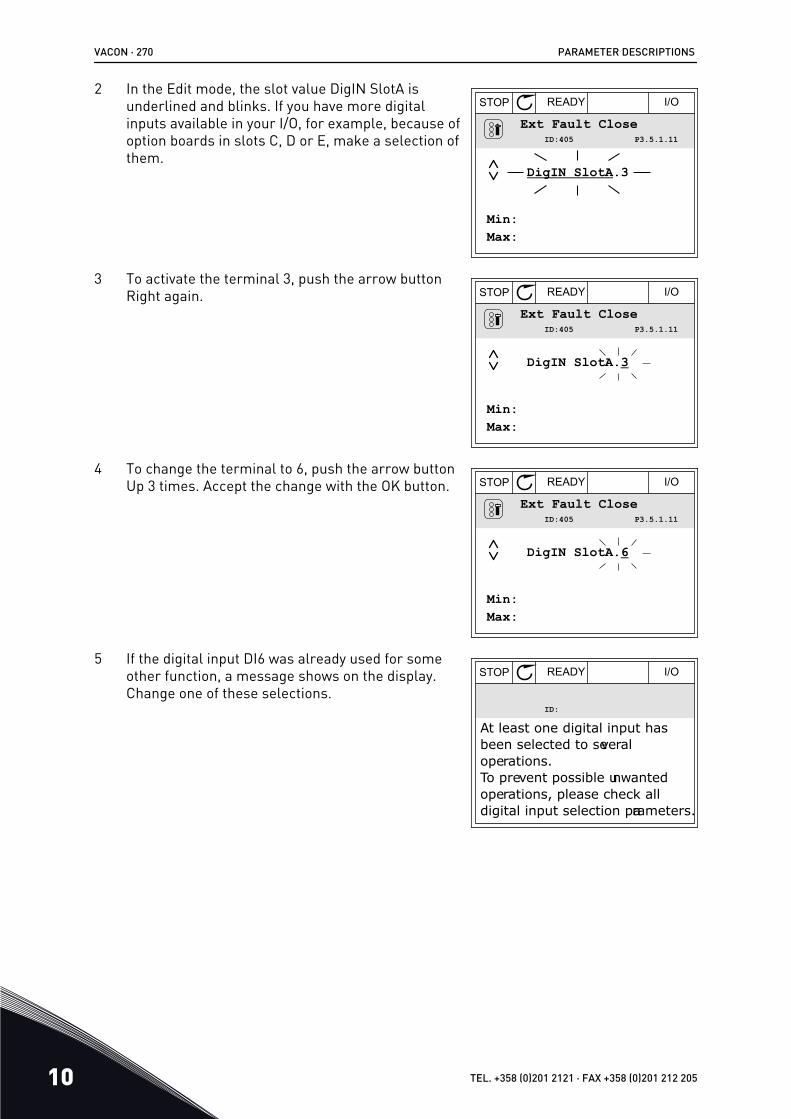
2 In the Edit mode, the slot value DigIN SlotA isunderlined and blinks. If you have more digitalinputs available in your I/O, for example, because ofoption boards in slots C, D or E, make a selection ofthem.
STOP READY I/O
Ext Fault CloseP3.5.1.11ID:405
Min:Max:
DigIN SlotA.3
3 To activate the terminal 3, push the arrow buttonRight again. STOP READY I/O
Ext Fault CloseP3.5.1.11ID:405
Min:Max:
DigIN SlotA.3
4 To change the terminal to 6, push the arrow buttonUp 3 times. Accept the change with the OK button. STOP READY I/O
Ext Fault CloseP3.5.1.11ID:405
Min:Max:
DigIN SlotA.6
5 If the digital input DI6 was already used for someother function, a message shows on the display.Change one of these selections.
STOP READY I/O
ID:
At least one digital input hasbeen selected to several operations.To prevent possible unwantedoperations, please check alldigital input selection parameters.
VACON · 270 PARAMETER DESCRIPTIONS
10 TEL. +358 (0)201 2121 · FAX +358 (0)201 212 205

PROGRAMMING IN THE TEXT DISPLAY1 Make a selection of a parameter. To go into the Edit
mode, push the OK button.READY FAULTALARMSTOPRUN
KEYPAD1/OREVFWD BUS
2 In the Edit mode, the letter D blinks. If you havemore digital inputs available in your I/O, forexample, because of option boards in slots C, D orE, make a selection of them.
READY FAULTALARMSTOPRUN
KEYPAD1/OREVFWD BUS
3 To activate the terminal 3, push the arrow buttonRight again. The letter D stops blinking.
READY FAULTALARMSTOPRUN
KEYPAD1/OREVFWD BUS
4 To change the terminal to 6, push the arrow buttonUp 3 times. Accept the change with the OK button.
READY FAULTALARMSTOPRUN
KEYPAD1/OREVFWD BUS
PARAMETER DESCRIPTIONS VACON · 271
24-HOUR SUPPORT +358 (0)201 212 575 · EMAIL: [email protected] 10

5 If the digital input DI6 was already used for someother function, a message scrolls on the display.Change one of these selections.
READY FAULTALARMSTOPRUN
KEYPAD1/OREVFWD BUS
After the steps, a digital signal to the digital input DI6 controls the function External FaultClose.The value of a function can be DigIN Slot0.1 (in the graphical display) or dI 0.1 (in the textdisplay). In these conditions, you did not give a terminal to the function, or the the input wasset to be always OPEN. This is the default value of most of parameters in the group M3.5.1.On the other hand, some inputs have the default value always CLOSED. Their value showsDigIN Slot0.2 in the graphical display and dI 0.2 in the text display.
NOTE!
You can also give time channels to digital inputs. There is more data about it inTable 12.1 The default values of parameters in the different applications.
10.5.1.2 Programming of analogue inputsYou can make a selection of the target input for the signal of the analogue frequencyreference from the available analogue inputs.
STOP READY I/O
ID:377 P3.5.2.1.1Analog Input 1
AI1 Signal Sel
AI1 Filter TimeAnINSlotA.1
0.10s
0-10V/0-20mAAIl Signal Range
A B
C
Fig. 53: The Analogue inputs menu in the graphical displayA. The graphical displayB. The name of the parameter
C. The value of the parameter, that is, theset analogue input
VACON · 272 PARAMETER DESCRIPTIONS
10 TEL. +358 (0)201 2121 · FAX +358 (0)201 212 205

READY FAULTALARMSTOPRUN
KEYPAD1/OREVFWD BUS
A
B
C
Fig. 54: The Analogue inputs menu in the text displayA. The text displayB. The name of the parameter
C. The value of the parameter, that is, theset analogue input
In the standard I/O board compilation, there are 2 analogue inputs available: the slot Aterminals 2/3 and 4/5.
Input type (graphi-cal display)
Input type(text dis-play)
Slot Input # Explanation
AnIN AI A 1 Analogue input #1 (terminals 2/3) on a board inSlot A (standard I/O board).
AnIN AI A 2 Analogue input #2 (terminals 4/5) on a board inSlot A (standard I/O board).
The location of the parameter P3.5.2.1.1 AI1 Signal Selection is the menu M3.5.2.1. Theparameter gets the default value AnIN SlotA.1 in the graphical display or AI A.1 in the textdisplay. The target input for the signal of the analogue frequency reference AI1 is then theanalogue input in the terminals 2/3. Use the dip switches to set the signal to be voltage orcurrent. See the Installation manual for more data.
Index Parameter Default ID Description
P3.5.2.1.1 AI1 Signal Selec-tion AnIN SlotA.1 377
To change the input from AI1 to, for example, the analogue input on your option board in slotC, obey these instructions.
PARAMETER DESCRIPTIONS VACON · 273
24-HOUR SUPPORT +358 (0)201 212 575 · EMAIL: [email protected] 10

PROGRAMMING OF ANALOGUE INPUTS IN THE GRAPHICAL DISPLAY1 To make a selection of the parameter, push the
arrow button Right. STOP READY I/O
Analogue Input 1
AI1 Filter Time
AI1 Signal Range
AnIN SlotA.1
0.10s
0-10V/0-20mA
AI1 Signal SelP3.5.2.1.1ID:377
2 In the Edit mode, the value AnIN SlotA is underlinedand blinks. STOP READY I/O
AI1 Signal Sel
AnIN SlotA.1
P3.5.2.1.1ID:377
Min:Max:
3 To change the value to AnIN SlotC, push the arrowbutton Up. Accept the change with the OK button. STOP READY I/O
AI1 Signal Sel
AnIN SlotC.1
P3.5.2.1.1ID:377
Min:Max:
PROGRAMMING OF ANALOGUE INPUTS IN THE TEXT DISPLAY1 To make a selection of the parameter, push the OK
button.READY FAULTALARMSTOPRUN
KEYPAD1/OREVFWD BUS
VACON · 274 PARAMETER DESCRIPTIONS
10 TEL. +358 (0)201 2121 · FAX +358 (0)201 212 205

2 In the Edit mode, the letter A blinks.READY FAULTALARMSTOPRUN
KEYPAD1/OREVFWD BUS
3 To change the value to C, push the arrow buttonUp. Accept the change with the OK button.
READY FAULTALARMSTOPRUN
KEYPAD1/OREVFWD BUS
PARAMETER DESCRIPTIONS VACON · 275
24-HOUR SUPPORT +358 (0)201 212 575 · EMAIL: [email protected] 10

10.5.1.3 Descriptions of signal sources
Source Function
Slot0.# Digital inputs:
You can use this function to set a digital signal to be in a constant OPENor CLOSED state. The manufacturer set some signals so that they arealways in the CLOSED state, for example parameter P3.5.1.15 (Run Ena-ble). The Run Enable signal is always on if you do not change it.# = 1: Always OPEN# = 2-10: Always CLOSED
Analogue inputs (used for test purposes):
# = 1: Analogue input = 0% of the signal strength# = 2: Analogue input = 20% of the signal strength# = 3: Analogue input = 30% of the signal strength etc.# = 10: Analogue input = 100% of the signal strength
SlotA.# Number (#) agrees to a digital input in slot A.
SlotB.# Number (#) agrees to a digital input in slot B.
SlotC.# Number (#) agrees to a digital input in slot C.
SlotD.# Number (#) agrees to a digital input in slot D.
SlotE.# Number (#) agrees to a digital input in slot E.
TimeChannel.# 1=Time Channel1, 2=Time Channel2, 3=Time Channel3
FieldbusCW.# Number (#) refers to a control word bit number.
FieldbusPD.# Number (#) refers to the process data 1 bit number.
VACON · 276 PARAMETER DESCRIPTIONS
10 TEL. +358 (0)201 2121 · FAX +358 (0)201 212 205

10.5.2 DEFAULT FUNCTIONS OF PROGRAMMABLE INPUTS
Table 114: Default functions of the programmable digital and analogue inputs
Input Terminal(s) Reference Function Parameter index
DI1 8 A.1 Control Signal 1 A P3.5.1.1
DI2 9 A.2 Control Signal 2 A P3.5.1.2
DI3 10 A.3 External Fault Close P3.5.1.11
DI4 14 A.4 Preset FrequencySelection 0
P3.5.1.21
DI5 15 A.5 Preset FrequencySelection 1
P3.5.1.22
DI6 16 A.6 Fault Reset Close P3.5.1.13
AI1 2/3 A.1 AI1 Signal Selection P3.5.2.1.1
AI2 4/5 A.2 AI2 Signal Selection P3.5.2.2.1
10.5.3 DIGITAL INPUTSThe parameters are functions that you can connect to a digital input terminal. The text DigInSlot A.2 means the second input on the slot A. It is also possible to connect the functions totime channels. The time channels work as terminals.
You can monitor the statuses of the digital inputs and the digital outputs in theMultimonitoring view.
P3.5.1.15 RUN ENABLE (ID 407)
When the contact is OPEN, the start of the motor is disabled.When the contact is CLOSED, the start of the motor is enabled.
To stop, the drive obeys the value of P3.2.5 Stop Function.
P3.5.1.16 RUN INTERLOCK 1 (ID 1041)
P3.5.1.17 RUN INTERLOCK 2 (ID 1042)
If an interlock is active, the drive cannot start.
You can use this function to prevent the start of the drive when the damper is closed. If youactivate an interlock during the operation of the drive, the drive stops.
P3.5.1.53 PARAMETER SET 1/2 SELECTION (ID 496)
The parameter gives the digital input which is used to select Parameter Set 1 or Set 2. Thefunction is enabled if other slots than DigIN Slot0 are selected to this parameter. Theselection of the parameter set can be made and the set changes only when the drive isstopped.
PARAMETER DESCRIPTIONS VACON · 277
24-HOUR SUPPORT +358 (0)201 212 575 · EMAIL: [email protected] 10

• Contact Open = Parameter Set 1 is set as the active set• Contact Closed = Parameter Set 2 is set as the active set
NOTE!
Parameter values are stored to Set 1 and Set 2 with parameters B6.5.4 Save to Set1 and B6.5.4 Save to Set 2. You can use these parameters with the keypad or the PCtool Vacon Live.
10.5.4 ANALOGUE INPUTS
P3.5.2.1.2 AI1 SIGNAL FILTER TIME (ID 378)
This parameter filters out disturbances in the analogue input signal. To activate thisparameter, give it a value that is bigger than 0.
NOTE!
A long filter time makes the regulation response slow.
[%]
100%
63%
ID378
t [s]
Filtered signal
Unfiltered signal
Analogue inputsignal
Fig. 55: The AI1 signal filtering
P3.5.2.1.3 AI1 SIGNAL RANGE (ID 379)
To set the type of the analogue input signal (current or voltage), use the dip switches on thecontrol board. See more in the Installation manual.
It is also possible to use the analogue input signal as frequency reference. The selection ofthe value 0 or 1 change the scaling of the analogue input signal.
VACON · 278 PARAMETER DESCRIPTIONS
10 TEL. +358 (0)201 2121 · FAX +358 (0)201 212 205

Selectionnumber Selection name Description
0 0...10V / 0...20mAThe range of the analogue input signal is 0...10V or 0...20mA(the dip switch settings on the control board tell which one).The input signal is 0...100%.
0% 100%50%0 mA 20 mA10 mA
Min freqreference
Max freqreference
Frequencyreference
Analogue inputsignal
[Hz]
[%]
Fig. 56: The analogue input signal range, selection 0
Selectionnumber Selection name Description
1 2...10V / 4...20mAThe range of the analogue input signal is 2...10V or 4...20mA(the dip switch settings on the control board tell which one).The input signal is 20...100%.
0 mA 20 mA10 mA4 mA
Min freqreference
Max freqreference
Frequencyreference
Analogue inputsignal0% 100%50%20%
[Hz]
[%]
Fig. 57: The analogue input signal range, selection 1
P3.5.2.1.4 AI1 CUSTOM. MIN (ID 380)
PARAMETER DESCRIPTIONS VACON · 279
24-HOUR SUPPORT +358 (0)201 212 575 · EMAIL: [email protected] 10

P3.5.2.1.5 AI1 CUSTOM. MAX (ID 381)
The parameters P3.5.2.1.4 and P3.5.2.1.5 let you adjust the range of the analogue inputsignal between -160 and 160% freely.
For example, you can use the analogue input signal as frequency reference, and set these 2parameters between 40 and 80%. In these conditions, the frequency reference changesbetween the Minimum frequency reference and the Maximum frequency reference, and theanalogue input signal changes between 8 and 16 mA.
Min freqreference
Max freqreference
Frequencyreference
Analogue inputsignal
AI custommin
AI custommax
0 mA 20 mA16 mA8 mA0% 100%80%40%
[Hz]
[%]
Fig. 58: AI1 signal custom. min/max
P3.5.2.1.6 AI1 SIGNAL INVERSION (ID 387)
In the inversion on the analogue input signal, the curve of the signal becomes the opposite.
It is possible to use the analogue input signal as frequency reference. The selection of thevalue 0 or 1 change scaling of the analogue input signal.
Selectionnumber Selection name Description
0 Normal
No inversion. The value 0% of the analogue input signalagrees to the Minimum Frequency Reference. The value100% of the the analogue input signal agrees to the Maxi-mum Frequency Reference.
VACON · 280 PARAMETER DESCRIPTIONS
10 TEL. +358 (0)201 2121 · FAX +358 (0)201 212 205

[Hz]
[%]0% 100%50%0 mA 20 mA10 mA
Min freqreference
Max freqreference
Frequencyreference
Analogue inputsignal
Fig. 59: AI1 signal inversion, selection 0
Selectionnumber Selection name Description
1 Inverted
Signal inversion. The value 0% of the analogue input signalagrees to the Maximum Frequency Reference. The value100% of the analogue input signal agrees to the MinimumFrequency Reference.
0% 100%50%0 mA 20 mA10 mA
Min freqreference
Max freqreference
Frequencyreference
[Hz]
Analogue inputsignal[%]
Fig. 60: AI1 signal inversion, selection 1
PARAMETER DESCRIPTIONS VACON · 281
24-HOUR SUPPORT +358 (0)201 212 575 · EMAIL: [email protected] 10

10.5.5 DIGITAL OUTPUTS
P3.5.3.2.1 BASIC RO1 FUNCTION (ID 11001)
Table 115: The output signals through RO1
Selectionnumber Selection name Description
0 Not used The output is not used.
1 Ready The AC drive is ready to operate.
2 Run The AC drive operates (the motor runs).
3 General fault A fault trip occurred.
4 General fault inverted A fault trip did not occur.
5 General alarm An alarm occurred.
6 Reversed The reverse command is given.
7 At speed The output frequency becomes the same as the set fre-quency reference.
8 Thermistor fault A thermistor fault occurred.
9 Motor regulator activated One of the limit regulators (for example current limit or tor-que limit) is activated.
10 Start signal active The start command of the drive is active.
11 Keypad control active The selection is keypad control (the active control place iskeypad).
12 I/O control B active The selection is I/O control place B (the active control placeis I/O B).
13 Limit supervision 1 The limit supervision becomes active, if the signal value goesbelow or above the set supervision limit (P3.8.3 or P3.8.7).
14 Limit supervision 2
15 Fire mode active The Fire mode function is active.
16 Flushing active The Jogging function is active.
17 Preset Frequency active The selection of preset frequency was made with digital inputsignals.
18 Quick Stop active The Quick stop function is activated.
19 PID in Sleep mode The PID controller is in the sleep mode.
20 PID Soft Fill activated The Soft fill function of the PID controller is activated.
21 PID feedback supervision The feedback value of the PID controller is not in the supervi-sion limits.
VACON · 282 PARAMETER DESCRIPTIONS
10 TEL. +358 (0)201 2121 · FAX +358 (0)201 212 205

Table 115: The output signals through RO1
Selectionnumber Selection name Description
22 ExtPID feedback supervision The feedback value of the external PID controller is not in thesupervision limits.
23 Input pressure alarm The input pressure of the pump is below the value that wasset with parameter P3.13.9.7.
24 Frost protection alarm The measured temperature of the pump is below the levelthat was set with parameter P3.13.10.5.
25 Time channel 1 The status of Time channel 1.
26 Time channel 2 The status of Time channel 2.
27 Time channel 3 The status of Time channel 3.
28 Fieldbus Control Word bit 13 The digital (relay) output control from the Fieldbus controlword bit 13.
29 Fieldbus Control Word bit 14 The digital (relay) output control from the Fieldbus controlword bit 14.
30 Fieldbus Control Word bit 15 The digital (relay) output control from the Fieldbus controlword bit 15.
31 Fieldbus Process Data In1 bit 0 The digital (relay) output control from the Fieldbus processdata In1, bit 0.
32 Fieldbus Process Data In1 bit 1 The digital (relay) output control from the Fieldbus processdata In1, bit 1.
33 Fieldbus Process Data In1 bit 2 The digital (relay) output control from the Fieldbus processdata In1, bit 2.
34 Maintenance counter 1 alarm The maintenance counter goes to the alarm limit that is setwith parameter P3.16.2.
35 Maintenance counter 1 fault The maintenance counter goes to the alarm limit that is setwith parameter P3.16.3.
36 Block Out.1 The output of the programmable Block 1. See parametermenu M3.19 Block Programming.
37 Block Out.2 The output of the programmable Block 2. See parametermenu M3.19 Block Programming.
38 Block Out.3 The output of the programmable Block 3. See parametermenu M3.19 Block Programming.
39 Block Out.4 The output of the programmable Block 4. See parametermenu M3.19 Block Programming.
40 Block Out.5 The output of the programmable Block 5. See parametermenu M3.19 Block Programming.
PARAMETER DESCRIPTIONS VACON · 283
24-HOUR SUPPORT +358 (0)201 212 575 · EMAIL: [email protected] 10

Table 115: The output signals through RO1
Selectionnumber Selection name Description
41 Block Out.6 The output of the programmable Block 6. See parametermenu M3.19 Block Programming.
42 Block Out.7 The output of the programmable Block 7.See parametermenu M3.19 Block Programming.
43 Block Out.8 The output of the programmable Block 8. See parametermenu M3.19 Block Programming.
44 Block Out.9 The output of the programmable Block 9. See parametermenu M3.19 Block Programming.
45 Block Out.10 The output of the programmable Block 10. See parametermenu M3.19 Block Programming.
46 Jockey pump control The control signal for the external jockey pump.
47 Priming pump control The control signal for the external priming pump.
48 Auto-cleaning active The Pump auto-cleaning function is activated.
49 Multipump K1 control The contactor control for the Multipump function.
50 Multipump K2 control The contactor control for the Multipump function.
51 Multipump K3 control The contactor control for the Multipump function.
52 Multipump K4 control The contactor control for the Multipump function.
53 Multipump K5 control The contactor control for the Multipump function.
54 Multipump K6 control The contactor control for the Multipump function.
55 Multipump K7 control The contactor control for the Multipump function.
56 Multipump K8 control The contactor control for the Multipump function.
69 Selected parameter set
Shows the active parameter set:
OPEN = Parameter set 1 activeCLOSED = Parameter set 2 active
10.5.6 ANALOGUE OUTPUTS
P3.5.4.1.1. AO1 FUNCTION (ID 10050)
The contents of the analogue output signal 1 are specified in this parameter. The scaling ofthe analogue output signal depends on the signal.
VACON · 284 PARAMETER DESCRIPTIONS
10 TEL. +358 (0)201 2121 · FAX +358 (0)201 212 205

Selectionnumber Selection name Description
0 Test 0% (Not used) The analogue output is set to 0% or 20% so that it agreeswith parameter P3.5.4.1.3.
1 TEST 100% The analogue output is set to 100% of the signal (10V /20mA).
2 Output frequency The actual output frequency from 0 to Maximum frequencyreference.
3 Frequency reference The actual frequency reference from 0 to Maximum fre-quency reference.
4 Motor speed The actual motor speed from 0 to Motor nominal speed.
5 Output current The output current of the drive from 0 to Motor nominal cur-rent.
6 Motor torque The actual motor torque from 0 to motor nominal torque(100%).
7 Motor power The actual motor power from 0 to Motor nominal power(100%).
8 Motor voltage The actual motor voltage from 0 to Motor nominal voltage.
9 DC-link voltage The actual DC-link voltage 0…1000V.
10 PID Setpoint The actual setpoint value of the PID Controller (0…100%).
11 PID Feedback The actual feedback value of the PID Controller (0…100%).
12 PID output The output of the PID controller (0…100%).
13 ExtPID output The External PID controller output (0…100%).
14 Fieldbus Process Data In 1 Fieldbus Process Data In 1: 0…10000 (this agrees with 0…100.00%).
15 Fieldbus Process Data In 2 Fieldbus Process Data In 2: 0…10000 (this agrees with 0…100.00%).
16 Fieldbus Process Data In 3 Fieldbus Process Data In 3: 0…10000 (this agrees with 0…100.00%).
17 Fieldbus Process Data In 4 Fieldbus Process Data In 4: 0…10000 (this agrees with 0…100.00%).
18 Fieldbus Process Data In 5 Fieldbus Process Data In 5: 0…10000 (this agrees with 0…100.00%).
19 Fieldbus Process Data In 6 Fieldbus Process Data In 6: 0…10000 (this agrees with 0…100.00%).
20 Fieldbus Process Data In 7 Fieldbus Process Data In 7: 0…10000 (this agrees with 0…100.00%).
PARAMETER DESCRIPTIONS VACON · 285
24-HOUR SUPPORT +358 (0)201 212 575 · EMAIL: [email protected] 10

Selectionnumber Selection name Description
21 Fieldbus Process Data In 8 Fieldbus Process Data In 8: 0…10000 (this agrees with 0…100.00%).
22Block Out.1 The output of the programmable Block 1: 0…10000 (this
agrees with 0…100.00%). See parameter menu M3.19 Drivecustomizer.
23Block Out.2 The output of the programmable Block 2: 0…10000 (this
agrees with 0…100.00%). See parameter menu M3.19 Drivecustomizer.
24Block Out.3 The output of the programmable Block 3: 0…10000 (this
agrees with 0…100.00%). See parameter menu M3.19 Drivecustomizer.
25Block Out.4 The output of the programmable Block 4: 0…10000 (this
agrees with 0…100.00%). See parameter menu M3.19 Drivecustomizer.
26Block Out.5 The output of the programmable Block 5: 0…10000 (this
agrees with 0…100.00%). See parameter menu M3.19 Drivecustomizer.
27Block Out.6 The output of the programmable Block 6: 0…10000 (this
agrees with 0…100.00%). See parameter menu M3.19 Drivecustomizer.
28Block Out.7 The output of the programmable Block 7: 0…10000 (this
agrees with 0…100,00%). See parameter menu M3.19 Drivecustomizer.
29Block Out.8 The output of the programmable Block 8: 0…10000 (this
agrees with 0…100.00%). See parameter menu M3.19 Drivecustomizer.
30Block Out.9 The output of the programmable Block 9: 0…10000 (this
agrees with 0…100.00%). See parameter menu M3.19 Drivecustomizer.
31Block Out.10 The output of the programmable Block 10: 0…10000 (this
agrees with 0…100.00%). See parameter menu M3.19 Drivecustomizer.
P3.5.4.1.4 AO1 MINIMUM SCALE (ID 10053)
P3.5.4.1.5 AO1 MAXIMUM SCALE (ID 10054)
You can use these 2 parameters to adjust the scaling of the analogue output signal freely.The scale is defined in process units and it depends on the selection of parameter P3.5.4.1.1AO1 Function.
For example, you can make a selection of the output frequency of the drive for the contentsof the analogue output signal, and set parameters P3.5.4.1.4 and P3.5.4.1.5 between 10 and
VACON · 286 PARAMETER DESCRIPTIONS
10 TEL. +358 (0)201 2121 · FAX +358 (0)201 212 205

40 Hz. Then the output frequency of the drive changes between 10 and 40 Hz, and theanalogue output signal changes between 0 and 20 mA.
Max freqreference
Outputfrequency
Analogueoutput signal
AO minscale
AO maxscale
10 Hz 40 Hz
0%
100%
50%
0 mA
20 mA
10 mA
0 Hz [Hz]
[%]
Fig. 61: The scaling of the AO1 signal
10.6 PROHIBIT FREQUENCIES
In some processes it can be necessary to avoid some frequencies because they makeproblems of mechanical resonance. With the Prohibit frequencies function, it is possible toprevent the usage of these frequencies. When the input frequency reference increases, theinternal frequency reference stays at the low limit, until the input frequency reference isabove the high limit.
P3.7.1 PROHIBIT FREQUENCY RANGE 1 LOW LIMIT (ID 509)
P3.7.2 PROHIBIT FREQUENCY RANGE 1 HIGH LIMIT (ID 510)
P3.7.3 PROHIBIT FREQUENCY RANGE 2 LOW LIMIT (ID 511)
P3.7.4 PROHIBIT FREQUENCY RANGE 2 HIGH LIMIT (ID 512)
PARAMETER DESCRIPTIONS VACON · 287
24-HOUR SUPPORT +358 (0)201 212 575 · EMAIL: [email protected] 10

P3.7.5 PROHIBIT FREQUENCY RANGE 3 LOW LIMIT (ID 513)
P3.7.6 PROHIBIT FREQUENCY RANGE 3 HIGH LIMIT (ID 514)
Actual Reference
Requested Reference
Low Lim
Low Lim
High Lim
High Lim
Fig. 62: The prohibited frequencies
P3.7.7 RAMP TIME FACTOR (ID 518)
The Ramp Time Factor sets the acceleration and the deceleration time when the outputfrequency is in a prohibited frequency range. The value of the Ramp Time Factor is multipliedwith the value of P3.4.1.2 (Acceleration Time 1) or P3.4.1.3 (Deceleration Time 1). Forexample, the value 0.1 makes the acceleration/deceleration time ten times shorter.
Time [s]
Output Frequency
Low Lim
High Lim
Ramp TimeFactor = 2.5
Ramp TimeFactor = 0.3
[Hz]
Fig. 63: The parameter Ramp Time Factor
10.7 PROTECTIONS
P3.9.1.2 RESPONSE TO EXTERNAL FAULT (ID 701)
With this parameter, you can set the response of the drive to an external fault. If a faultoccurs, the drive can show a notification of it on the display of the drive. The notification is
VACON · 288 PARAMETER DESCRIPTIONS
10 TEL. +358 (0)201 2121 · FAX +358 (0)201 212 205

made in a digital input. The default digital input is DI3. You can also program the responsedata into a relay output.
10.7.1 MOTOR THERMAL PROTECTIONSThe motor thermal protection prevents the motor from becoming too hot.
The AC drive can supply a current that is higher than the nominal current. The high currentcan be necessary to the load, and it must be used. In these conditions, there is a risk of athermal overload. Low frequencies have a higher risk. At low frequencies, the cooling effectand the capacity of the motor decrease. If the motor has an external fan, the load reductionat low frequencies is small.
The motor thermal protection is based on calculations. The protection function uses theoutput current of the drive to know what is the load on the motor. If the control board is notenergised, the calculations are reset.
To adjust the thermal protection of the motor, use the parameters from P3.9.2.1 to P3.9.2.5.You can monitor the thermal status of the motor on the display of the control panel. SeeChapter 3 User interfaces.
NOTE!
If you use long motor cables (max. 100 m) with small drives (≤1.5 kW), the motorcurrent that the drive measures can be much higher than the actual motor current.It is because there are capacitive currents in the motor cable.CAUTION!
Make sure that the airflow to the motor is not blocked. If the airflow is blocked, thefunction does not protect the motor, and the motor can become too hot. This cancause damage to the motor.
P3.9.2.3 ZERO SPEED COOLING FACTOR (ID 706)
When the speed is 0, this function calculates the cooling factor in relation to the point wherethe motor operates at a nominal speed without external cooling.
The default value is set for conditions where there is no external fan. If you use an externalfan, you can set the value higher than without the fan, for example at 90%.
If you change parameter P3.1.1.4 (Motor Nominal Current), parameter P3.9.2.3 isautomatically set to its default value.
Although you change this parameter, it does not have an effect on the maximum outputcurrent of the drive. Only parameter P3.1.3.1 Motor Current Limit can change the maximumoutput current.
The corner frequency for the thermal protection is 70% of the value of the parameterP3.1.1.2 Motor Nominal Frequency.
PARAMETER DESCRIPTIONS VACON · 289
24-HOUR SUPPORT +358 (0)201 212 575 · EMAIL: [email protected] 10

ffn
ID706=40%
0
IT100%
Overload area
Pcooling
Corner freq
Fig. 64: The motor thermal current IT curve
P3.9.2.4 MOTOR THERMAL TIME CONSTANT (ID 707)
The time constant is the time during which the calculated warming curve becomes 63% of itstarget value. The length of the time constant is in relation with the dimension of the motor.The bigger the motor, the longer the time constant.
In different motors, the motor thermal time constant is different. It also changes betweendifferent motor manufacturers. The default value of the parameter changes from dimensionto dimension.
The t6-time is the time in seconds that the motor can safely operate at 6 times the ratedcurrent. It is possible that the motor manufacturer gives the data with the motor. If you knowthe t6 of the motor, you can set the time constant parameter with its help. Usually, the motorthermal time constant in minutes is 2*t6. When the drive is in the STOP state, the timeconstant is internally increased to 3 times the set parameter value, because the coolingoperates based on convection.
VACON · 290 PARAMETER DESCRIPTIONS
10 TEL. +358 (0)201 2121 · FAX +358 (0)201 212 205

I/IT
100%
63%
t
T
t
T = Motor thermal time constant
Current
Fig. 65: The motor thermal time constant
P3.9.2.5 MOTOR THERMAL LOADABILITY (ID 708)
For example, if you set the value to 130%, the motor goes to the nominal temperature with130% of the motor nominal current.
PARAMETER DESCRIPTIONS VACON · 291
24-HOUR SUPPORT +358 (0)201 212 575 · EMAIL: [email protected] 10

I/IT
t
t
T
Current
Fault/Alarm
Loadability 80%Loadability 100%Loadability 130%
105%
Trip area
Fig. 66: The calculation of the motor temperature
10.7.2 MOTOR STALL PROTECTIONThe motor stall protection function gives protection to the motor against short overloads. Anoverload can be caused, for example, by a stalled shaft. It is possible to set the reaction timeof the stall protection shorter than that of the motor thermal protection.
The stall status of the motor is specified with parameters P3.9.3.2 Stall Current and P3.9.3.4Stall Frequency Limit. If the current is higher than the limit, and the output frequency islower than the limit, the motor is in a stall status.
The stall protection is a type of overcurrent protection.
NOTE!
If you use long motor cables (max. 100 m) with small drives (≤1.5 kW), the motorcurrent that the drive measures can be much higher than the actual motor current.It is because there are capacitive currents in the motor cable.
VACON · 292 PARAMETER DESCRIPTIONS
10 TEL. +358 (0)201 2121 · FAX +358 (0)201 212 205

P3.9.3.2 STALL CURRENT (ID 710)
You can set the value of this parameter between 0.0 and 2*IL. For a stall status to occur, thecurrent must be higher than this limit. If parameter P3.1.3.1 Motor Current Limit changes,this parameter is automatically calculated to 90% of the current limit.
NOTE!
The value of the Stall Current must be below the motor current limit.
f
I
ID710
ID712
Stall area
Fig. 67: The stall characteristics settings
P3.9.3.3 STALL TIME LIMIT (ID 711)
You can set the value of this parameter between 1.0 and 120.0 s. This is the maximum timefor the stall status to be active. An internal counter counts the stall time.
If the stall time counter value goes above this limit, the protection causes the drive to trip.
10.7.3 UNDERLOAD (DRY PUMP) PROTECTIONThe motor underload protection makes sure that there is a load on the motor when the driveoperates. If the motor loses the load, a problem can occur in the process. For example, a beltcan break or a pump become dry.
You can adjust the motor underload protection with parameters P3.9.4.2 (UnderloadProtection: Field Weakening Area Load) and P3.9.4.3 (Underload Protection: Zero FrequencyLoad). The underload curve is a squared curve between the zero frequency and the fieldweakening point. The protection is not active below 5 Hz. The underload time counter doesnot operate below 5 Hz.
The values of the underload protection parameters are set in percentage of the nominaltorque of the motor. To find the scaling ratio for the internal torque value, use the data in thename plate data of the motor, the motor nominal current and the nominal current of thedrive IH. If you use another current than the nominal motor current, the precision of thecalculation decreases.
PARAMETER DESCRIPTIONS VACON · 293
24-HOUR SUPPORT +358 (0)201 212 575 · EMAIL: [email protected] 10

NOTE!
If you use long motor cables (max. 100 m) with small drives (≤1.5 kW), the motorcurrent that the drive measures can be much higher than the actual motor current.It is because there are capacitive currents in the motor cable.
P3.9.4.2 UNDERLOAD PROTECTION: FIELD WEAKENING AREA LOAD (ID 714)
You can set the value of this parameter between 10.0 and 150.0% x TnMotor. This value is thelimit for the minimum torque when the output frequency is above the field weakening point.
If you change parameter P3.1.1.4 (Motor Nominal Current), this parameter goesautomatically back to its default value. See 10.7.3 Underload (Dry pump) protection.
ID714
ID715
f
5 Hz
Underload area
Torque
Field weakeningpoint
Fig. 68: Setting of the minimum load
P3.9.4.4 UNDERLOAD PROTECTION: TIME LIMIT (ID 716)
You can set the time limit between 2.0 and 600.0 s.
This is the maximum time for an underload status to be active. An internal counter countsthe underload time. If the value of the counter goes above this limit, the protection causesthe drive to trip. The drive trips as is set in parameter P3.9.4.1 Underload Fault. If the drivestops, the underload counter goes back to 0.
VACON · 294 PARAMETER DESCRIPTIONS
10 TEL. +358 (0)201 2121 · FAX +358 (0)201 212 205

ID716Trip area
Time
Underload time counter
Underload•No underl.
Trip/warningID713
Fig. 69: The Underload time counter function
P3.9.5.1 QUICK STOP MODE (ID 1276)
P3.9.5.2 (P3.5.1.26) QUICK STOP ACTIVATION (ID 1213)
P3.9.5.3 QUICK STOP DECELERATION TIME (ID 1256)
P3.9.5.4 RESPONSE TO QUICK STOP FAULT (ID 744)
With the quick stop function, you can stop the drive in an unusual procedure from I/O orFieldbus in unusual conditions. When the quick stop function is active, you can make thedrive decelerate and stop. It is possible to program an alarm or fault to put a mark in thefault history that there was a request for a quick stop.
CAUTION!
Do not use the quick stop function as an emergency stop. An emergency stop muststop the power supply to the motor. The quick stop function does not do this.
PARAMETER DESCRIPTIONS VACON · 295
24-HOUR SUPPORT +358 (0)201 212 575 · EMAIL: [email protected] 10

ORIN 1IN 2
FB
I/O
Yes
Control Word B12
Quick Stop Activ. Normal operation
Start stopsequence
according toQuick Stop Modeand Quick Stop
DecelerationTime
Quick StopActivated
Quick StopActivated
NODrive
stopped?
Yes
Drive forced to Not Ready status and alarm/fault
triggered according to
Quick Stop Fault
Fig. 70: The quick stop logic
P3.9.8.1 ANALOGUE INPUT LOW PROTECTION (ID 767)
Use the AI Low Protection to find failures in the analogue input signals. This function givesprotection only to the analogue inputs that are used as frequency reference or in the PID/ExtPID controllers.
You can have the protection on when the drive is in the RUN status, or in the RUN and STOPstatuses.
VACON · 296 PARAMETER DESCRIPTIONS
10 TEL. +358 (0)201 2121 · FAX +358 (0)201 212 205

Selectionnumber Selection name Description
1 Protection disabled
2 Protection enabled in RUN sta-tus
The protection is enabled only when the drive is in the RUNstatus.
3 Protection enabled in RUN andSTOP status
The protection is enabled in the 2 statuses, RUN and STOP.
P3.9.8.2 ANALOGUE INPUT LOW FAULT (ID 700)
If AI Low Protection is enabled with parameter P3.9.8.1, this parameter gives a response forthe fault code 50 (Fault ID 1050).
The AI low protection function monitors the signal level of the analogue inputs 1-6. If theanalogue input signal becomes less than 50% of the minimum signal for 500 ms, an AI Lowfault or alarm shows.
NOTE!
You can use the value Alarm + Previous Freq only when you use analogue input 1 oranalogue input 2 as frequency reference.
Selectionnumber Selection name Description
0 No Action AI Low Protection is not used.
1 Alarm
2 Alarm, preset frequency The frequency reference is set as in P3.9.1.13 Preset AlarmFrequency.
3 Alarm, previous frequency The last valid frequency is kept as frequency reference.
4 Fault The drive stops as is set in P3.2.5 Stop Mode.
5 Fault, coasting The drive stops by coasting.
10.8 AUTOMATIC RESET
P3.10.1 AUTOMATIC RESET (ID 731)
Use parameter P3.10.1 to enable the Automatic reset function. To make a selection of faultsthat are reset automatically, give the value 0 or 1 to parameters from P3.10.6 to P3.10.13.
NOTE!
The automatic reset function is available only for some fault types.
PARAMETER DESCRIPTIONS VACON · 297
24-HOUR SUPPORT +358 (0)201 212 575 · EMAIL: [email protected] 10

P3.10.3 WAIT TIME (ID 717)
P3.10.4 TRIAL TIME (ID 718)
Use this parameter to set the trial time for the automatic reset function. During the trialtime, the automatic reset function tries to reset the faults that occur. The time count startsfrom the first automatic reset. The next fault starts the trial time count again.
P3.10.5 NUMBER OF TRIALS (ID 759)
If the number of trials during the trial time is more than the value of this parameter, apermanent fault shows. If not, the fault goes out of view after the trial time is completed.
With parameter P3.10.5, you can set the maximum number of automatic reset trials duringthe trial time set in P3.10.4. The fault type does not have an effect on the maximum number.
Fault trigger
Autoreset
Trial time
Wait time
Wait time
Wait time
ID717
Reset 1 Reset 2
Trial timeID718
Fault active
Alarm
Number of trials: (ID759 = 2)
ID717 ID717
Fig. 71: The Automatic reset function
10.9 TIMER FUNCTIONS
The timer functions make it possible for the internal RTC (Real Time Clock) to controlfunctions. All the functions that can be controlled with a digital input, can also be controlledwith the RTC, with time channels 1-3. It is not necessary to have an external PLC to control adigital input. You can program the closed and opened intervals of the input internally.
To get the best results of the timer functions, install a battery, and make the settings of theReal Time Clock carefully in the Start-up wizard. The battery is available as an option.
VACON · 298 PARAMETER DESCRIPTIONS
10 TEL. +358 (0)201 2121 · FAX +358 (0)201 212 205

NOTE!
We do not recommend that you use the timer functions without an auxiliary battery.The time and date settings of the drive are reset at each power down, if there is nobattery for the RTC.
TIME CHANNELS
You can assign the output of the interval and/or timer functions to time channels 1-3. You canuse the time channels to control on/off type functions, for example relay outputs or digitalinputs. To configure the on/off logic of the time channels, assign intervals and/or timers tothem. A time channel can be controlled by many different intervals or timers.
P AssignToChannel
Interval 1
Interval 2
Interval 3Interval 4
Timer 1Timer 2Timer 3
Interval 5
TimeChannel 1
TimeChannel 2
TimeChannel 3
Fig. 72: Assigning intervals and timers to time channels is flexible. Every interval and timer has aparameter with which you can assign them to a time channel.
INTERVALS
Use parameters to give each interval an ON Time and OFF Time. It is the daily active time ofthe interval during the days set with parameters From Day and To Day. For example, with theparameter settings below, the interval is active from 7 am to 9 am from Monday to Friday.The time channel is like a digital input, but virtual.
ON Time: 07:00:00OFF Time: 09:00:00From Day: MondayTo Day: Friday
TIMERS
Use the timers to set a time channel as active for a period with a command from a digitalinput or a time channel.
PARAMETER DESCRIPTIONS VACON · 299
24-HOUR SUPPORT +358 (0)201 212 575 · EMAIL: [email protected] 10

Duration
Remainingtime
Activation
Time
OUT
Fig. 73: The activation signal comes from a digital input or a virtual digital input, like a timechannel. The timer counts down from the falling edge.
The parameters below will set the timer active when the digital input 1 on the slot A isclosed. They will also keep the timer active for 30 s after it is opened.
• Duration: 30 s• Timer: DigIn SlotA.1
You can use a duration of 0 seconds to override a time channel that is activated from a digitalinput. There is no off delay after the falling edge.
Example:
Problem:
The AC drive is in a warehouse and controls air conditioning. It must operate between 7 amand 5 pm on weekdays and between 9 am and 1 pm on weekends. It is also necessary for thedrive to operate outside these hours, if there are personnel in the building. The drive mustcontinue to operate 30 minutes after the personnel has left.
Solution:
Set 2 intervals, 1 for weekdays and 1 for weekends. A timer is also necessary to activate theprocess outside the set hours. See the configuration below.
Interval 1P3.12.1.1: ON Time: 07:00:00P3.12.1.2: OFF Time: 17:00:00P3.12.1.3: Days: Monday, Tuesday, Wednesday, Thursday, FridayP3.12.1.4: Assign to channel: Time channel 1
VACON · 300 PARAMETER DESCRIPTIONS
10 TEL. +358 (0)201 2121 · FAX +358 (0)201 212 205

17:00:00
07:00:00
M3.12.1.3ID:1466
STOP READY I/O
Interval 1
Days
OFF Time
ON Time
0Fig. 74: Using timer functions to make an interval
M3.12.1.3ID:
STOP READY I/O
Edit
Help
Add to favourites
Days
Fig. 75: Going into the Edit mode
STOP READY I/O
DaysM3.12.1.3.1ID:
MondayTuesdayWednesday
ThursdayFriday
Sunday
Fig. 76: The checkbox selection for the weekdays
Interval 2P3.12.2.1: ON Time: 09:00:00P3.12.2.2: OFF Time: 13:00:00P3.12.2.3: Days: Saturday, SundayP3.12.2.4: Assign to channel: Time channel 1
Timer 1P3.12.6.1: Duration: 1800 s (30 min)P3.12.6.2: Timer 1: DigIn SlotA.1 (The parameter is located in the digital inputs menu.)P3.12.6.3: Assign to channel: Time channel 1P3.5.1.1: Control signal 1 A: Time Channel 1 for the I/O Run command
PARAMETER DESCRIPTIONS VACON · 301
24-HOUR SUPPORT +358 (0)201 212 575 · EMAIL: [email protected] 10

Interval 1Days = Monday to Friday
ON = 07:00:00 hrs OFF = 17:00:00 hrs
Interval 2Days = Saturday and Sunday
ON = 09:00:00 hrs OFF = 13:00:00 hrs
P Ctrl Signal 1A
Digital input 1 on Slot A Timer 1
Duration = 1800 s
Time channel 1 Start/Stop
Fig. 77: Time channel 1 is used as the control signal for the start command instead of a digitalinput
10.10 PID CONTROLLER
P3.13.1.9 DEAD BAND (ID 1056)
P3.13.1.10 DEAD BAND DELAY (ID 1057)
If the actual value stays in the dead band area for a time set in Dead Band Delay, the PIDcontroller output is locked. This function prevents wear and unwanted movements of theactuators, for example valves.
Dead band (ID1056) Reference
Dead band delay (ID1057)
Output locked
Actual value
Fig. 78: The Dead band function
VACON · 302 PARAMETER DESCRIPTIONS
10 TEL. +358 (0)201 2121 · FAX +358 (0)201 212 205

10.10.1 FEEDFORWARD
P3.13.4.1 FEEDFORWARD FUNCTION (ID 1059)
Accurate process models are usually necessary for the Feedforward function. In someconditions, a gain and offset type of feedforward is sufficient. The feedforward part does notuse the feedback measurements of the actual controlled process value. The feedforwardcontrol uses other measurements that have an effect on the controlled process value.
EXAMPLE 1:
You can control the water level of a tank with flow control. The target water level is set as asetpoint, and the actual level as feedback. The control signal monitors the flow that comesin.
The outflow is like a disturbance that you can measure. With the measurements of thedisturbance, you can try to adjust this disturbance with a feedforward control (gain andoffset) that you add to the PID output. The PID controller reacts much faster to changes inthe outflow than if you only measure the level.
PID+ +
LT FT
FFWLevel ref
Level control
Outflowcontrol
Fig. 79: The feedforward control
10.10.2 SLEEP FUNCTION
P3.13.5.1 SP1 SLEEP FREQUENCY (ID 1016)
The drive goes to sleep mode (that is, the drive stops) when the output frequency of the driveis less than the frequency limit that is set in this parameter.
The value of this parameter is used when the signal of the PID controller setpoint is takenfrom the setpoint source 1.
PARAMETER DESCRIPTIONS VACON · 303
24-HOUR SUPPORT +358 (0)201 212 575 · EMAIL: [email protected] 10

Criterias for going to sleep mode
• Output frequency remains below sleep frequency for longer than defined sleep delaytime
• PID feedback signal remains above defined wake up level
Criterias for waking from sleep
• PID feedback signal falls below defined wake up level
NOTE!
A wrong set wake up level might not allow the drive to go into sleep mode
P3.13.5.2 SP1 SLEEP DELAY (ID 1017)
The drive goes to sleep mode (that is, the drive stops) when the output frequency of the driveis less than the sleep frequency limit for longer than the time that is set in this parameter.
The value of this parameter is used when the signal of the PID controller setpoint is takenfrom the setpoint source 1.
P3.13.5.3 SP1 WAKE-UP LEVEL (ID 1018)
P3.13.5.4 SP1 WAKE-UP MODE (ID 1019)
With these parameters, you can set when the drive wakes up from the sleep mode.
The drive wakes up from the sleep mode when the value of PID Feedback goes below theWake-up level.
This parameter defines if Wake-up level is used as a static absolute level or as a relativelevel which follows PID setpoint value.
Selection 0 = Absolute level (The wake-up level is a static level that does not follow thesetpoint value.)Selection 1 = Relative setpoint (The wake-up level is an offset below the actual setpointvalue. The wake-up level follows the actual setpoint.)
PID SetpointSetpoint
tWake Up Level
Fig. 80: Wake-up Mode: absolute level
VACON · 304 PARAMETER DESCRIPTIONS
10 TEL. +358 (0)201 2121 · FAX +358 (0)201 212 205

PID SetpointSetpoint
tWake Up Level
Fig. 81: Wake-up Mode: relative setpoint
P3.13.5.5 SP1 SLEEP BOOST (ID 1793)
Before the drive goes to the sleep state, the PID regulation setpoint increases automatically,which gives a higher process value. The sleep state is longer, also when there is somemoderate leakage.
The boost level is used when there is a frequency threshold and delay, and the drive goes tothe sleep state. After the increment in the setpoint by the actual value, the boost incrementof the setpoint is erased and the drive goes to the sleep state and the motor stops. The boostincrement is positive with the direct PID regulation (P3.13.1.8 = Normal) and negative withthe reverse PID regulation (P3.13.1.8 =Inverted).
If the actual value does not go to the increment setpoint, the boost value is erased after thetime set with P3.13.5.5. The drive goes to the normal regulation with the normal setpoint.
In a Multipump setup, if an auxiliary pump starts during the boost, the boost sequence stopsand the normal regulation continues.
P3.13.5.5 SP2 SLEEP FREQUENCY (ID 1075)
See the description of parameter P3.13.5.1.
P3.13.5.6 SP2 SLEEP DELAY (1076)
See the description of parameter P3.13.5.2.
P3.13.5.7 SP2 WAKE-UP LEVEL (ID 1077)
See the description of parameter P3.13.5.3.
P3.13.5.8 SP2 WAKE-UP MODE (ID 1020)
See the description of parameter P3.13.5.4
P3.13.5.11 SP2 SLEEP BOOST (ID 1794)
See the description of parameter P3.13.5.5.
10.10.3 FEEDBACK SUPERVISIONUse the feedback supervision to make sure that the PID Feedback value (the process valueor the actual value) stays in the set limits. With this function you can, for example, find a pipebreak and stop the flooding.
PARAMETER DESCRIPTIONS VACON · 305
24-HOUR SUPPORT +358 (0)201 212 575 · EMAIL: [email protected] 10

These parameters set the range in which the PID Feedback signal stays in correctconditions. If the PID Feedback signal does not stay in the range, and this continues longerthan the delay, a Feedback supervision fault (the fault code 101) shows.
P3.13.6.1 ENABLE FEEDBACK SUPERVISION (ID 735)
Regulating mode
Upper limit(ID736)
Lower limit(ID758)
Actual value
Delay (ID737)
Alarm or fault
Reference
Fig. 82: The Feedback supervision function
P3.13.6.2 UPPER LIMIT (ID 736)
P3.13.6.3 LOWER LIMIT (ID 758)
Set the upper limit and the lower limit around the reference. When the actual value is less ormore than the limits, a counter starts to count up. When the actual value is between thelimits, the counter counts down. When the counter gets a value that is higher than the valueof P3.13.6.4 Delay, an alarm or a fault shows. You can make a selection of the response withparameter P3.13.6.5 (Response to PID1 Supervision Fault).
10.10.4 PRESSURE LOSS COMPENSATIONWhen you pressurise a long pipe that has many outlets, the best position for the sensor is inthe middle of the pipe (the position 2 in the figure). You can also put the sensor directly afterthe pump. This gives the right pressure directly after the pump, but farther in the pipe, thepressure drops with the flow.
VACON · 306 PARAMETER DESCRIPTIONS
10 TEL. +358 (0)201 2121 · FAX +358 (0)201 212 205

With flow
Position 2Position 1
Pressure
No flow
Pipe length
PT PT
Fig. 83: The position of the pressure sensor
P3.13.7.1 ENABLE COMPENSATION FOR SETPOINT 1 (ID 1189)
P3.13.7.2 SETPOINT 1 MAX COMPENSATION (ID 1190)
The sensor is put in position 1. The pressure in the pipe stays constant when there is no flow.But with flow, the pressure decreases farther in the pipe. To compensate for this, lift thesetpoint as the flow increases. Then the output frequency makes an estimate of the flow, andthe setpoint increases linearly with the flow.
PARAMETER DESCRIPTIONS VACON · 307
24-HOUR SUPPORT +358 (0)201 212 575 · EMAIL: [email protected] 10

With flow and compensation
Position 1 Position 2
Pressure
No flow
Pipe length
Setpoint
Max Freq and FlowMin Freq and Flow
Setpoint + Max compensation
Setpoint
PTPT
Fig. 84: Enable setpoint 1 for pressure loss compensation
10.10.5 SOFT FILLThe Soft fill function is used to move the process to a set level at a slow speed before the PIDcontroller starts to control. If the process does not go to the set level during the timeout, afault shows.
You can use the function to fill an empty pipe slowly and prevent strong currents of waterthat could break the pipe.
We recommend that you always use the Soft fill function when you use the Multipumpfunction.
VACON · 308 PARAMETER DESCRIPTIONS
10 TEL. +358 (0)201 2121 · FAX +358 (0)201 212 205

P3.13.8.1 SOFT FILL FUNCTION (ID 1094)
The operation mode of the Soft fill function is specified by this parameter.
0 = Disabled1 = Enabled (Level)
The drive operates at a constant frequency (P3.13.8.2 Soft Fill Frequency) until the PIDfeedback signal goes to the soft fill level (P3.13.8.3 Soft Fill Level). The PID controller startsthe regulation.In addition, if the PID feedback signal does not go to the soft fill level in the soft fill timeout(P3.13.8.4 Soft Fill Timeout), a soft fill fault shows (P3.13.8.4 Soft Fill Timeout is set togreater than 0).The soft fill mode is used in vertical installations.
2 = Enabled (Timeout)
The drive operates at a constant frequency (P3.13.8.2 Soft Fill Frequency) until the soft filltime (P3.13.8.4 Soft Fill Timeout) goes. After the soft fill time, the PID controller starts theregulation.In this mode, the soft fill fault is not available.The soft fill mode is used in horizontal installations.
P3.13.8.2 SOFT FILL FREQUENCY (ID 1055)
The parameter gives the constant frequency reference, which is used when the Soft fillfunction is active.
P3.13.8.3 SOFT FILL LEVEL (ID 1095)
To use this parameter, select the option Enabled (Level) with P3.13.8.1 Soft Fill Function.
This parameter gives the PID feedback signal level, above which the Soft fill function isdeactivated and the PID controller starts the regulation.
P3.13.8.4 SOFT FILL TIMEOUT (ID 1096)
If you selected the option Enabled (Level) in parameter P3.13.8.1 Soft Fill Function, parameterSoft Fill Timeout gives the timeout for the soft fill level, after which the soft fill fault shows.
If you selected the option Enabled (Timeout) in parameter P3.13.8.1 Soft Fill Function,parameter Soft Fill Timeout gives the quantity of time that the drive operates at the constantsoft fill frequency (P3.13.8.2 Soft Fill Frequency) before the PID controller starts theregulation.
P3.13.8.5 SOFT FILL FAULT RESPONSE (ID 738)
The selection of the fault response for F100, PID Soft Fill Timeout Fault.
0 = No action1 = Alarm2 = Fault (stop according to stop mode)3 = Fault (stop by coasting)
PARAMETER DESCRIPTIONS VACON · 309
24-HOUR SUPPORT +358 (0)201 212 575 · EMAIL: [email protected] 10

10.10.6 INPUT PRESSURE SUPERVISIONUse the Input pressure supervision to make sure that there is enough water in the inlet ofthe pump. When there is enough water, the pump does not suck air and there is no suctioncavitation. To use the function, install a pressure sensor on the pump inlet.
If the input pressure of the pump goes below the set alarm limit, an alarm shows. Thesetpoint value of the PID controller decreases and causes the output pressure of the pump todecrease. If the pressure goes below the fault limit, the pump is stops and a fault shows.
PT
Mains
Inlet Outlet
Fig. 85: The location of the pressure sensor
Input Pressure
SupervisionFault Level
Input Pressure Alarm(Digital output signal)
Supervision Alarm Level
Input Pressure Monitor
PID Setpoint
PID Setpoint
SupervisionFault Delay
SupervisionFault Delay
Motor Running YesNo
PID SetpointReduction
Fig. 86: The Input pressure supervision function
VACON · 310 PARAMETER DESCRIPTIONS
10 TEL. +358 (0)201 2121 · FAX +358 (0)201 212 205

10.10.7 SLEEP FUNCTION WHEN NO DEMAND IS DETECTEDThis function makes sure that the pump does not operate at a high speed when there is nodemand in the system.
The function becomes active when the PID feedback signal and the output frequency of thedrive stay in the specified hysteresis areas for longer than set with parameter P3.13.10.4SNDD Supervision Time.
There are different hysteresis settings for the PID feedback signal and the output frequency.The hysteresis for the PID feedback (SNDD Error Hysteresis P3.13.10.2) is given in theselected process units around the PID setpoint value.
When the function is active, a short-time bias value (SNDD Actual Add) is added internally tothe feedback value.• If there is no demand in the system, the PID output and the output frequency of the drive
decrease to the direction of 0. If the PID feedback value stays in the hysteresis area, thedrive goes to the Sleep mode.
• If the PID feedback value does not stay in the hysteresis area, the function is deactivatedand the drive continues to operate.
A
B
EFG I
J
DHA
B C
G
H
K
C
DE
t
t
Hz
Fig. 87: Sleep, no demand detectedA. The output frequency of the driveB. The PID feedback valueC. The PID setpoint valueD. SNDD Frequency Hysteresis (P3.13.10.3)E. SNDD Error Hysteresis (P3.13.10.2)
The hysteresis area around the PIDsetpoint value.
F. SNDD Actual Add (P3.13.10.5)G. SNDD Supervision Time (P3.13.10.4)
H. The PID feedback value and the outputfrequency of the drive are in thehysteresis areas for the set time (SNDDSupervision Time). A bias value (SNDDActual Add) is added to the PID feedbackvalue.
I. SP1 Sleep Delay Time (P3.13.5.2)J. The drive goes to the Sleep mode.K. Process Unit (P3.13.1.4)
P3.14.1.7 PROCESS UNIT SELECTION (ID 1636)
P3.14.1.8 PROCESS UNIT MAX (ID 1664)
PARAMETER DESCRIPTIONS VACON · 311
24-HOUR SUPPORT +358 (0)201 212 575 · EMAIL: [email protected] 10

P3.14.1.9 PROCESS UNIT MIN (ID 1665)
With parameters Process Unit Selection, Process Unit Min and Process Unit Max you can seeall the parameters and monitoring values related to PID Control (feedback and setpoint, forexample) in the selected process units (bar or Pascal, for example).
Parameters Process Unit Min and Max are set to agree with the range of the feedbacksensor.
Example:In the pump application, the signal range of the pressure sensor is 4-20mA, and 0-10 barpressure. The process unit settings of the PID controller are:
• ProcessUnitSel. = bar• ProcessUnitMin = 0,00 bar• ProcessUnitMax = 10,00 bar
10.10.8 MULTI-SETPOINT
P3.13.12.1 MULTI-SETPOINT 0 (ID 15560)
P3.13.12.2 MULTI-SETPOINT 1 (ID 15561)
P3.13.12.3 MULTI-SETPOINT 2 (ID 15562)
P3.13.12.4 MULTI-SETPOINT 3 (ID 15563)
P3.13.12.5 MULTI-SETPOINT 4 (ID 15564)
P3.13.12.6 MULTI-SETPOINT 5 (ID 15565)
P3.13.12.7 MULTI-SETPOINT 6 (ID 15566)
P3.13.12.8 MULTI-SETPOINT 7 (ID 15567)
P3.13.12.9 MULTI-SETPOINT 8 (ID 15568)
P3.13.12.10 MULTI-SETPOINT 9 (ID 15569)
P3.13.12.11 MULTI-SETPOINT 10 (ID 15570)
P3.13.12.12 MULTI-SETPOINT 11 (ID 15571)
VACON · 312 PARAMETER DESCRIPTIONS
10 TEL. +358 (0)201 2121 · FAX +358 (0)201 212 205

P3.13.12.13 MULTI-SETPOINT 12 (ID 15572)
MULTI-SETPOINT 13 (ID 15573)
P3.13.12.14 MULTI-SETPOINT 13 (ID 15573)
P3.13.12.15 MULTI-SETPOINT 14 (ID 15574)
P3.13.12.16 MULTI-SETPOINT 15 (ID 15575)
The parameters show the preset setpoint values of the PID controller. The values are shownin the process unit that is selected with parameter P3.13.1.4 Process Unit Selection.
NOTE!
The parameters change automatically if parameters P3.13.1.5 Process Unit Min orP3.13.1.6 Process Unit Max are changed.
10.10.8.1 P3.13.12.17 Multi-Setpoint Selection, bit 0 (ID 15576)
P3.13.12.18 MULTI-SETPOINT SELECTION, BIT 1 (ID 15577)
P3.13.12.19 MULTI-SETPOINT SELECTION, BIT 2 (ID 15578)
P3.13.12.20 MULTI-SETPOINT SELECTION, BIT 3 (ID 15579)
The parameters give the digital input signals that are used to select the Multi-Setpoint 0-15.To enable the Multi-Setpoint function, set parameter P3.13.2.5 PID Setpoint Selection orP3.13.2.10 Setpoint Source 2 Selection to Multi-Setpoint.
PARAMETER DESCRIPTIONS VACON · 313
24-HOUR SUPPORT +358 (0)201 212 575 · EMAIL: [email protected] 10

Table 116: The selection of the Multi-Setpoint value
Digital input signals (x = digital input signal is active) Selected setpointvalue
Multi-Setpoint Sel0(P3.13.12.17)
Multi-Setpoint Sel1(P3.13.12.18)
Multi-Setpoint Sel2(P3.13.12.19)
Multi-Setpoint Sel3(P3.13.12.20)
Multi-Setpoint 0
x Multi-Setpoint 1
x Multi-Setpoint 2
x x Multi-Setpoint 3
x Multi-Setpoint 4
x x Multi-Setpoint 5
x x Multi-Setpoint 6
x x x Multi-Setpoint 7
x Multi-Setpoint 8
x x Multi-Setpoint 9
x x Multi-Setpoint 10
x x x Multi-Setpoint 11
x x Multi-Setpoint 12
x x x Multi-Setpoint 13
x x x Multi-Setpoint 14
x x x x Multi-Setpoint 15
10.11 MULTIPUMP FUNCTION
The Multipump function lets you control a system where the maximum of 8 motors, forexample, pumps, fans or compressors operate in parallel. The internal PID controller of thedrive operates the necessary quantity of motors and controls the speed of the motors, whenthere is demand.
10.11.1 MULTIPUMP (MULTIDRIVE) COMMISSIONING CHECKLISTThe check list helps you in the configuration of the basic settings of the Multipump(multidrive) system. If you use the keypad for parametrisation, the application wizard helpsyou to make the basic settings.
Start the commissioning with the drives that have the PID feedback signal (pressure sensor,for example) connected to an analogue input (default: AI2). Go through all the drives in thesystem.
VACON · 314 PARAMETER DESCRIPTIONS
10 TEL. +358 (0)201 2121 · FAX +358 (0)201 212 205

Step Action
1
Examine the wiring.• See the correct power cabling (mains cable, motor cable) of the drive in Installation Man-
ual.• See the correct control cabling (I/O, PID feedback sensor, communication) in Fig. 18
Electric wiring diagramme of the Multipump (multidrive) system, example 1A and in Fig. 16 The default control connections of Multipump (multidrive) application.
• If redundancy is necessary, make sure that the PID feedback signal (by default: AI2) isconnected to a minimum of 2 drives. See the wiring instructions in Fig. 18 Electric wiring diagramme of the Multipump (multidrive) system, example 1A.
2
Do a power-up of the drive and start the parametrisation.• Start the parametrisation with the drives that have the PID feedback signal connected.
These drives can operate as the master of the Multipump system.• You can do the parametrisation with the keypad or PC the tool.
3
Select the Multipump (multidrive) application configuration with parame-ter P1.2.• Most of the Multipump-related settings and configurations are made automatically,
when the Multipump (multidrive) application is selected with parameter P1.2 Application(ID 212). See 2.5 Multipump (multidrive) application wizard.
• If you use the keypad for the parametrisation, the Application wizard starts when param-eter P1.2 Application (ID 212) is changed. The Application wizard helps you with Multi-pump-related questions.
4 Set the motor parameters.• Set the motor nameplate parameters specified by the rating plate of the motor.
5
Set the total number of drives used in the Multipump system.• This value is set with parameter P1.35.14 Quick Setup Parameter Menu.• The same parameter is in the menu Parameters -> Group 3.15 -> P3.15.2• By default, the Multipump system has 3 pumps (drives).
6
Select the signals that are connected to the drive.• Go to parameter P1.35.16 (Quick Setup Parameter Menu).• The same parameter is in the menu Parameters -> Group 3.15 -> P3.15.4.• If the PID feedback signal is connected, the drive can operate as the master of the Multi-
pump system. If the signal is not connected, the drive operates as a slave unit.• Select Signals connected, if the start and the PID feedback signals (the pressure sensor,
for example) are connected to the drive.• Select Start signal only, if only the start signal is connected to the drive (the PID feedback
signal is not connected).• Select Not connected, if the start or the PID feedback signals are not connected to the
drive.
PARAMETER DESCRIPTIONS VACON · 315
24-HOUR SUPPORT +358 (0)201 212 575 · EMAIL: [email protected] 10

Step Action
7
Set the ID number of the pump.• Go to parameter P1.35.15 (Quick Setup Parameter Menu).• The same parameter is in the menu Parameters -> Group 3.15 -> P3.15.3.• Each drive in the Multipump system must have an ID number that no other drive has for
the correct communication between drives. The ID numbers must be in a numericalorder and start from number 1.
• The drives, which have a PID feedback signal connected, have the smallest ID numbers(for example, ID 1 and ID 2). This gives the shortest possible start-up delay when you doa power-up of the system.
8
Configure the Interlock function.• Go to parameter P1.35.17 (Quick Setup Parameter Menu).• The same parameter is in menu Parameters -> Group 3.15 -> P3.15.5.• By default, the interlock function is disabled.• Select Enabled, if the interlock signal is connected to the digital input DI5 of the drive.
The interlock signal is the digital input signal that tells if this pump is available in theMultipump system.
• Select Not Used, if the interlock signal is not connected to the digital input DI5 of thedrive. The system sees that all the pumps in the Multipump system are available.
9
Examine the source of the PID setpoint signal.• By default, the PID setpoint value comes from parameter P1.35.9 Keypad Setpoint 1.• If it is necessary, you can change the source of the PID setpoint signal with parameter
P1.35.8. You can select the analogue input or Fieldbus Process Data In 1-8, for example.
The basic settings of the Multipump system are completed. You can use the check list alsowhen you configure the next drives in the system.
10.11.2 SYSTEM CONFIGURATIONThe Multipump function has 2 different configurations. The configutation is specified by thequantity of drives in the system.
SINGLE DRIVE CONFIGURATION
The Single drive mode controls a system of 1 variable speed pump and the maximum of 7auxiliary pumps. The internal PID controller of the drive controls the speed of 1 pump andgives control signals with relay outputs to start or stop the auxiliary pumps. Externalcontactors are necessary for the switch of the auxiliary pumps to the mains.
VACON · 316 PARAMETER DESCRIPTIONS
10 TEL. +358 (0)201 2121 · FAX +358 (0)201 212 205

3 ~
PT
M1 M2 M3 M8
M1
M2
M3
M8
Start/Stop
RO2RO3RO8
Fig. 88: Single drive configuration (PT = pressure sensor)
MULTIDRIVE CONFIGURATION
The Multidrive modes (Multimaster and Multifollower) control a system that has themaximum 8 variable speed pumps. Each pump is controlled by a drive. The internal PIDcontroller of the drive controls all pumps. The drives use a communication bus (ModbusRTU) for communication.The figure below shows the Multidrive configuration principle. See also the general electricdiagram of a multipump system in Fig. 18 Electric wiring diagramme of the Multipump (multidrive) system, example 1A.
PARAMETER DESCRIPTIONS VACON · 317
24-HOUR SUPPORT +358 (0)201 212 575 · EMAIL: [email protected] 10

3 ~
PT
M1 M2 M3 M8
M1
M2
M3
M8
Start/Stop
Fig. 89: Multidrive configuration (PT = pressure sensor)
P3.15.1 MULTIPUMP MODE (ID 1785)
The configuration and operation mode of Multipump system is specified by this parameter.
0 = SINGLE DRIVE
The Single drive mode controls a system that has 1 pump that can change speed and themaximum of 7 auxiliary pumps. The internal PID controller of the drive controls the speed of1 pump and gives control signals with relay outputs to start or stop the auxiliary pumps.External contactors are necessary for the switch of the auxiliary pumps to the mains.1 of the pumps is connected to the drive and controls the system. When the pump in controlsees that it is necessary to have more capacity (operates at the maximum frequency), thedrive gives the control signal with the relay output to start the next auxiliary pump. When theauxiliary pump starts, the pump in control continues to control and starts from the minimumfrequency.When the pump that controls the system sees that there is too much capacity (operates atthe minimum frequency), the pump makes the started auxiliary pump to stop. If no auxiliarypumps operate when the pump in control sees the overcapacity, the pump goes to the Sleepmode (if the Sleep function is enabled).
VACON · 318 PARAMETER DESCRIPTIONS
10 TEL. +358 (0)201 2121 · FAX +358 (0)201 212 205

P1 P2 P3
BRPM
fmin
fmax
t
Fig. 90: Control in the Single drive modeP1 The pump that controls the system B The auxiliary pumps connected to the
mains (direct on-line)
1 = MULTIFOLLOWER
The Multifollower mode controls a system that has the maximum 8 pumps that can changespeed. Each pump is controlled by a drive. The internal PID controller of the drive controls allthe pumps.1 of the pumps always controls the system. When the pump in control sees that it isnecessary to have more capacity (operates at the maximum frequency), the pump uses thecommunication bus to make the next pump to start. The next pump increases speed andstarts to operate at the speed of the pump in control. Auxiliary pumps operate at the speed ofthe pump that controls the system.When the pump that controls the system sees that there is too much capacity (operates atthe minimum frequency), it makes the started pump to stop. If no auxiliary pumps operatewhen the pump in control sees overcapacity, the pump goes to the Sleep mode (if the Sleepfunction is enabled).
A
P1 P2 P3
fmax
fmin
RPM
t
Fig. 91: Control in the Multifollower modeP1 The pump controls the system. P2 The pump follows the speed of P1.
PARAMETER DESCRIPTIONS VACON · 319
24-HOUR SUPPORT +358 (0)201 212 575 · EMAIL: [email protected] 10

P3 The pump follows the speed of P1. A Curve A shows the auxiliary pumps thatfollow the speed of pump 1.
1 = MULTIMASTER
The Multimaster mode controls a system that has the maximum 8 pumps that can changespeed. Each pump is controlled by a drive. The internal PID controller of the drive controls allthe pumps.1 of the pumps always controls the system. When the pump in control sees that it isnecessary to have more capacity (operates at the maximum frequency), it locks to a constantproduction speed and makes the next pump to start and to control the system.When the pump that controls the system sees that there is too much capacity (operates atthe minimum frequency), it stops. The pump that operates at a constant production speedstarts to control the system. If there are many pumps that operate at a constant productionspeed, the started pump starts to control the system. If no pumps operate at a constantproduction speed when the pump in control sees the overcapacity, the pump goes to theSleep mode (if the Sleep function is enabled).
P1 P2 P3
A
B
fmax
fmin
RPM
t
Fig. 92: Control in the Multimaster modeA. Curves A shows the control of the pumps B. The pumps are locked to the constant
production frequency
P3.15.2 NUMBER OF PUMPS (ID 1001)
The total quantity of pumps in the installation is specified by this parameter. The maximumnumber of pumps in the Multipump system is 8.
Set this parameter in the installation. If you remove 1 drive to do the servicing of the pump,for example, it is not necessary to change this parameter.
NOTE!
In the Multifollower and Multimaster modes, all drives must have the same value inthis parameter for the correct communication between the drives.
P3.15.3 PUMP ID NUMBER (ID 1500)
This parameter is used only in the Multifollower and Multimaster modes.
VACON · 320 PARAMETER DESCRIPTIONS
10 TEL. +358 (0)201 2121 · FAX +358 (0)201 212 205

Each drive (pump) in the installation must have a number that no other drive has. The firstdrive in the system must have the ID number 1 and the numbers of the drives must be in anumerical order.
Pump number 1 is always the primary master of the Multipump system. Drive number 1controls the process and the PID controller. The PID feedback and the PID setpoint signalsmust be connected to the drive number 1.
If the drive number 1 is not available in the system, there is a power-down of the drive, forexample, the next drive starts to operate as a secondary master of the Multipump system.
NOTE!
The communication between the drives is not correct, if:• the Pump ID numbers are not in a numerical order (start from 1), or• 2 drives have the same ID number.
P3.15.4 START AND FEEDBACK SIGNAL CONFIGURATION (ID 1782)
Connect the start command and the process feedback (PID feedback) signals to the drive inquestion with this parameter.
0 = The start and the PID feedback signals not connected to the drive in question1 = Only the start signals connected to the drive in question2 = The start and the PID feedback signals connected to the drive in question
NOTE!
The operation mode (master or slave) in the Multipump system is specified by thisparameter. The drives that have the start command and the PID feedback signalsconnected, can operate as the master drive in the Multipump system. If there aremany drives in the Multipump system that have all the signals connected, the drivewith the lowest Pump ID Number (P3.15.3) starts to operate as the master.
10.11.3 INTERLOCKSThe interlocks tell the Multipump system that a motor is not available. This can occur whenthe motor is removed from the system for maintenance or bypassed for manual control.
P3.15.5 PUMP INTERLOCKING (ID 1032)
To use the interlocks, enable the parameter P3.15.2. Select the status for each motor with adigital input (the parameters from P3.5.1.34 to P3.5.1.39). If the value of the input is CLOSED,that is, active, the Multipump logic connects the motor to the Multipump system.
10.11.4 FEEDBACK SENSOR CONNECTION IN A MULTIPUMP SYSTEMYou get the best precision and redundancy in the Multipump system when you use feedbacksensors for each drive.
PARAMETER DESCRIPTIONS VACON · 321
24-HOUR SUPPORT +358 (0)201 212 575 · EMAIL: [email protected] 10

4
5
6
7
4
5
6
7
4
5
6
7
-
+
-
+
-
+
Actual value
(0)4..20mA
Actual value
(0)4..20mA
Actual value
(0)4..20mA
Drive 1: Standard I/O Board
Drive 2: Standard I/O Board
Drive 3: Standard I/O Board
Terminal Signal
Terminal Signal
Terminal Signal
A12+
A12-
24Vout
GND
Analogue input 2+
Analogue input 2-
24V auxiliary voltage
I/O ground
A12+
A12-
24Vout
GND
Analogue input 2+
Analogue input 2-
24V auxiliary voltage
I/O ground
A12+
A12-
24Vout
GND
Analogue input 2+
Analogue input 2-
24V auxiliary voltage
I/O ground
Fig. 93: Wiring of the feedback sensors for each drive
You can also use the same sensor for all the drives. The sensor (transducer) can be suppliedby an external 24V power supply or from the control board the drive.
VACON · 322 PARAMETER DESCRIPTIONS
10 TEL. +358 (0)201 2121 · FAX +358 (0)201 212 205

4
5
12
13
17
4
5
12
13
17
4
5
12
13
17
-
+
Actual value
(0)4..20mA
Drive 1: Standard I/O Board
Terminal Signal
A12+
A12-
24Vout
GND
Analogue input 2+
Analogue input 2-
24V auxiliary voltage
I/O ground
CM Common for DI1-DI6
Drive 2: Standard I/O Board
Terminal Signal
A12+
A12-
24Vout
GND
Analogue input 2+
Analogue input 2-
24V auxiliary voltage
I/O ground
CM Common for DI1-DI6
Drive 3: Standard I/O Board
Terminal Signal
A12+
A12-
24Vout
GND
Analogue input 2+
Analogue input 2-
24V auxiliary voltage
I/O ground
CM Common for DI1-DI6
Fig. 94: Wiring of the same sensor for all drives (supplied from the I/O board of the drive)
PARAMETER DESCRIPTIONS VACON · 323
24-HOUR SUPPORT +358 (0)201 212 575 · EMAIL: [email protected] 10

4
5
6
7
4
5
6
7
4
5
6
7
-
+
-+
Actual value
External 24V Supply
(0)4..20mA
Drive 1: Standard I/O Board
Drive 2: Standard I/O Board
Drive 3: Standard I/O Board
Terminal Signal
Terminal Signal
Signal
A12+
A12-
24Vout
GND
Analogue input 2+
Analogue input 2-
24V auxiliary voltage
I/O ground
A12+
A12-
24Vout
GND
Analogue input 2+
Analogue input 2-
24V auxiliary voltage
I/O ground
A12+
A12-
24Vout
GND
Analogue input 2+
Analogue input 2-
24V auxiliary voltage
I/O ground
Fig. 95: Wiring of the same sensor for all drives (supplied from an external 24V)
If a sensor is supplied from the I/O board of the drive and the diodes are connected betweenterminals 12 and 17, the digital inputs must be isolated from the ground. Set the isolationDIP switch to Float.The digital inputs are active when they are connected to GND, which is the default condition.
VACON · 324 PARAMETER DESCRIPTIONS
10 TEL. +358 (0)201 2121 · FAX +358 (0)201 212 205

AB
C
Fig. 96: Isolation DIP switchA. Digital inputsB. Float
C. Connected to GND (default)
P3.15.4 AUTOCHANGE (ID 1027)
Selectionnumber Selection name Description
0 Disabled
In normal operation, the sequence of the motors is always 1,2, 3, 4, 5. The sequence can change during the operation ifyou add or remove interlocks. After the drive stops, thesequence always changes back.
1 Enabled (interval)
The system changes the sequence at intervals to wear themotors equally. You can adjust the intervals of the autoch-ange with parameter P3.15.8. The timer of the autochangeinterval operates only when the Multipump system operates.
2 Enabled (real time)
The start sequence changes at the selected weekday andtime of day. Make the selection with parameters P3.15.9 andP3.15.10.
To use this mode, an RTC battery must be installed in thedrive.
ExmpleAfter an autochange, the first motor is put last. The other motors move up 1 position.
The start sequence of the motors: 1, 2, 3, 4, 5--> Autochange -->The start sequence of the motors: 2, 3, 4, 5, 1--> Autochange -->
The start sequence of the motors: 3, 4, 5, 1, 2
PARAMETER DESCRIPTIONS VACON · 325
24-HOUR SUPPORT +358 (0)201 212 575 · EMAIL: [email protected] 10

P3.15.7 AUTOCHANGED PUMPS (ID 1028)
Selectionnumber Selection name Description
0 Auxiliary pumpsThe drive is always connected to Motor 1. The interlocks donot have an effect on Motor 1. Motor 1 is not included in theautochange logic.
1 All pumpsIt is possible to connect the drive to any of the motors in thesystem. The interlocks have an effect on all the motors. Allthe motors are included in the autochange logic.
WIRING
The connections are different for the parameter values 0 and 1.
SELECTION 0, AUXILIARY PUMPS
The drive is directly connected to Motor 1. The other motors are auxiliary motors. They areconnected to the mains by contactors, and controlled by relays of the drive. The autochangeor the interlock logic do not have an effect on Motor 1.
SELECTION 1, ALL PUMPS
To include the regulating motor in the autochange or in the interlock logic, obey theinstructions in the figure below. 1 relay controls each motor. The contactor logic alwaysconnects the first motor to the drive, and the next motors to the mains.
VACON · 326 PARAMETER DESCRIPTIONS
10 TEL. +358 (0)201 2121 · FAX +358 (0)201 212 205

K1 K1.1 K2 K2.1 K3 K3.1
K1 K1.1 K2 K2.1 K3 K3.1
K1.1 K1
K2
K3 K2 K3 K3 K1 K3 K1 K2 K1
K2.1 K2
K1
K3.1 K3
K2
Mains
M1 M2 M3
from relayMotor 2 controlMotor 1 control
from relayMotor 3 control
from relay
Fig. 97: Selection 1
P3.15.8 AUTOCHANGE INTERVAL (ID 1029)
The interval time between the autochanges is specified by this parameter. To use theparameter, select Enabled (interval) with parameter P3.15.6 Autochange.
The autochange occurs, if:
PARAMETER DESCRIPTIONS VACON · 327
24-HOUR SUPPORT +358 (0)201 212 575 · EMAIL: [email protected] 10

• the Multipump system operates (the start command is active),• the autochange interval time goes,• the pump that controls the system operates below the frequency specified by parameter
P3.15.11 Autochange Frequency Limit,• the number of pumps that operate is less or equal to the limit specified by parameter
P3.15.12 Autochange Pump Limit.
P3.15.9 AUTOCHANGE DAYS (ID 1786)
P3.15.10 AUTOCHANGE TIME (ID 1787)
The weekdays and the time of day for the autochange are specified by these parameters. Touse the parameters, select Enabled (real time) with parameter P3.15.6 Autochange.
The autochange occurs, if:
• the Multipump system operates (the start command is active),• it is the autochange weekday and the time of day,• the pump that controls the system operates below the frequency specified by parameter
P3.15.11 Autochange Frequency Limit,• the number of pumps that operate is less or equal to the limit specified by parameter
P3.15.12 Autochange Pump Limit.
P3.15.11 AUTOCHANGE FREQUENCY LIMIT (ID 1031)
P3.15.12 AUTOCHANGE PUMP LIMIT (ID 1030)
These parameters give the level below which the used capacity must stay for the autochangeto occur.
If the number of pumps that operate in the Multipump system is less or equal to the limitspecified by parameter P3.15.12 and the pump that controls the system operates below thefrequency specified by parameter P3.15.11, the autochange can occur.
NOTE!
These parameters are used in the Single drive mode, because the autochange canrestart the system (depending on the quantity of motors that operate).
In the Multifollower and Multimaster modes, set these parameters to the maximum values tomake it possible for the autochange to occur immediately at the autochange time. In theMultifollower and Multimaster modes, the quantity of pumps that operate does not have aneffect on the autochange.
P3.15.13 BANDWIDTH (ID 1097)
P3.15.14 BANDWIDTH DELAY (ID 1098)
The conditions to start or stop the pumps in the Multipump system are specified by theseparameters. The number of pumps that operate increases or decreases, if the PID controllercannot keep the process value (feedback) in the specified bandwidth around the setpoint.
VACON · 328 PARAMETER DESCRIPTIONS
10 TEL. +358 (0)201 2121 · FAX +358 (0)201 212 205

The bandwidth area is specified as a percentage of the PID setpoint. When the PID feedbackvalue stays in the bandwidth area, it is not necessary to increase or decrease the number ofpumps that operate.
When the feedback value goes out of the bandwidth area, the quantity of time specified byparameter P3.15.14 must go before the number of pumps that operate increases ordecreases. More pumps must be available.
P3.15.13
1
2
P3.15.14 P3.15.14
AC
B
D
Fig. 98: The start or stop of the auxiliary pumps (P3.15.13 = Bandwidth, P3.15.14 = Bandwidthdelay)A. The pump that controls the system
operates at a frequency that is near themaximum (-2Hz). This increases thenumber of pumps that operate.
B. The pump that controls the systemoperates at a frequency that is near theminimum (+2Hz). This decreases thenumber of pumps that operate.
C. The number pumps that operateincreases or decreases, if the PIDcontroller cannot keep the process valuefeedback in the specified bandwidtharound the setpoint.
D. The specified bandwidth around thesetpoint.
P3.15.16 RUNNING PUMP LIMIT (ID 1187)
The maximum number of pumps that operate at the same time in the Multipump system isspecified by this parameter.
NOTE!
If the value of parameter P3.15.2 Number of Pumps changes, the same valuechanges automatically to this parameter.
Example:The Multipump system has 3 pumps, but only 2 pumps can operate at the same time. Thethird pump is installed in the system for redundancy. The number of pumps that can operateat the same time:
• Running Pump Limit = 2
PARAMETER DESCRIPTIONS VACON · 329
24-HOUR SUPPORT +358 (0)201 212 575 · EMAIL: [email protected] 10

P3.15.17.1 PUMP 1 INTERLOCK (ID 426)
The digital input of the drive, where the interlock (feedback) signal of pump 1 is read, isspecified by this parameter.
When the Pump interlocking function (P3.15.5) is enabled, the drive reads the statuses of thedigital inputs of the pump interlock (feedback). When the input is CLOSED, the motor isavailable for the Multipump system.
When the Pump interlocking function (P3.15.5) is disabled, the drive does not read thestatuses of the digital inputs of the pump interlock (feedback). The Multipump system seesall pumps in the system as available.
• In the Single drive mode, the digital input signal that is selected with thisparameter shows the interlock status of pump 1 in the Multipump system.
• In the Multifollower and Multimaster modes, the digital input signal that isselected with this parameter shows the interlock status of the pump that isconnected to this drive.
P3.15.17.2 PUMP 2 INTERLOCK (ID 427)
P3.15.17.3 PUMP 3 INTERLOCK (ID 428)
P3.15.17.4 PUMP 4 INTERLOCK (ID 429)
P3.15.17.5 PUMP 5 INTERLOCK (ID 430)
P3.15.17.6 PUMP 6 INTERLOCK (ID 486)
P3.15.17.7 PUMP 7 INTERLOCK (ID 487)
P3.15.17.8 PUMP 8 INTERLOCK (ID 488)
The digital inputs of the drive, where the interlock (feedback) signals of pumps 2-8 are read,are specified by these parameters.
NOTE!
These parameters are used in the Single drive mode only.When the Pump interlocking function (P3.15.5) is enabled, the drive reads the statuses of thedigital inputs of the pump interlock. When the input is CLOSED, the motor is available for theMultipump system.
When the Pump interlocking function (P3.15.5) is disabled, the drive does not read thestatuses of the digital inputs of the pump interlock. The Multipump system sees all pumps inthe system as available.
VACON · 330 PARAMETER DESCRIPTIONS
10 TEL. +358 (0)201 2121 · FAX +358 (0)201 212 205

10.11.5 OVERPRESSURE SUPERVISIONYou can use the Overpressure supervision function in a Multipump system. For example,when you close the primary valve of the pump system quickly, the pressure in the pipe linesincreases. The pressure can increase too quickly for the PID controller. To prevent that thepipes break, the overpressure supervision stops the auxiliary motors in the Multipumpsystem.
P3.15.16.1 ENABLE OVERPRESSURE SUPERVISION (ID 1698)
The overpressure supervision monitors the feedback signal of the PID controller, that is, thepressure. If the signal becomes higher than the overpressure level, it stops all the auxiliarypumps immediately. Only the regulating motor continues to operate. When the pressuredecreases, the system continues to operate, and connects the auxiliary motors again one at atime.
Pressure
M2
Superv.Alarm Level
PID Feedback
PID Setpoint
M3 ONOFF
ONOFF
ID1699
ID167
(ID21)
Fig. 99: The Overpressure supervision function
10.11.6 PUMP RUNTIME COUNTERSIn the Multipump system, the time that each pump operates is monitored by a runtimecounter. For example, the order that the pumps start is specified by the runtime countervalues to make the wear of the pumps in the system more equal.The pump runtime counters also tell the operator to do a maintenance on a pump(parameters P3.15.19.4 - P3.15.19.5 below).The Pump runtime counters are in the monitoring menu, see Table 23 Multipump monitoring.
P3.15.19.1 SET RUNTIME COUNTER (ID 1673)
When you push this button-type parameter, the runtime counter(s) of the selected pump(s)(P3.15.19.3) are set to the specified value.
P3.15.19.2 SET RUNTIME COUNTER: VALUE (ID 1087)
This parameter gives the runtime counter value, which is set to the runtime counter(s) of thepump(s) that are selected with P3.15.19.3.
PARAMETER DESCRIPTIONS VACON · 331
24-HOUR SUPPORT +358 (0)201 212 575 · EMAIL: [email protected] 10

NOTE!
In the Multimaster and Multifollower modes, it is possible to reset or set thenecessary value only to the counter Pump (1) Running Time. In the Multimaster andMultifollower modes, the monitoring value Pump (1) Running Time shows the hoursof the pump that is connected to this drive, the ID number of the pump has noeffect.
EXAMPLE
In the Multipump (single drive) system, pump number 4 is replaced with a new pump. Thecounter value of Pump 4 Running Time must be reset.
1. Select Pump 4 with parameter P3.15.19.3.2. Set parameter P3.15.19.2 value to 0 h.3. Push the button-type parameter P3.15.19.1.4. Pump 4 Running Time is reset.
P3.15.19.3 SET RUNTIME COUNTER: PUMP SELECTION (ID 1088)
Use this parameter to select the pump(s), for which the runtime counter value is reset or anecessary value is set, when the button-type parameter P3.15.19.1 is pushed.
If the Multipump (single drive) mode is selected, the next selections are available:
0 = All Pumps1 = Pump (1)2 = Pump 23 = Pump 34 = Pump 45 = Pump 56 = Pump 67 = Pump 78 = Pump 8
If the Multifollower or Multimaster mode is selected, only the next selection is available:
1 = Pump (1)
NOTE!
In the Multimaster and Multifollower modes, it is possible to reset or to set anecessary value only for the the Pump (1) Running Time. In the Multimaster andMultifollower modes, the monitoring value Pump (1) Running Time shows the hoursof the pump that is connected to this drive, the ID number of the pump has noeffect.
EXAMPLE
In the Multipump (single drive) system, pump number 4 is replaced with a new pump. Thecounter value of Pump 4 Running Time must be reset.
VACON · 332 PARAMETER DESCRIPTIONS
10 TEL. +358 (0)201 2121 · FAX +358 (0)201 212 205

1. Select Pump 4 with parameter P3.15.19.3.2. Set parameter P3.15.19.2 value to 0 h.3. Push the button-type parameter P3.15.19.1.4. Pump 4 Running Time is reset.
P3.15.22.1 STAGING FREQUENCY (ID 15545)
Use the parameter to adjust the output frequency level, at which the auxiliary pump starts inthe Multipump system.
NOTE!
The parameter has no effect, if its value is set above Max Frequency Reference(P3.3.1.2).
By default, an auxiliary pump starts (is staged), if the PID feedback signal goes below thespecified bandwidth area and the pump that controls the system operates at the maximumfrequency.
The auxiliary pump can start at a lower frequency to get better process values or to use lessenergy. Then, use the parameter to set the start frequency of the auxiliary pump below themaximum frequency.
M PID Feedback
P Banwidth Delay
Start Aux PumpV
M Output Freq
M PID Setpoint
P Freq Ref MaxP Staging Freq
P Bandwidth
LTIN1IN2
GTIN1IN2MIN
IN1IN2
SUBIN1IN2
ANDIN1IN2
ON-DELAYIN OUTTIME
Fig. 100: Staging frequency
P3.15.22.2 DE-STAGING FREQUENCY (ID 15546)
Use the parameter is to adjust the output frequency level, at which the auxiliary pump stopsin the Multipump system.
NOTE!
The parameter has no effect, if its value is set below Min Frequency Reference(P3.3.1.1).
By default, an auxiliary pump stops (is de-staged), if the PID feedback signal goes above thespecified bandwidth area and the pump that controls the system operates at the minimumfrequency.
The auxiliary pump can stop at a higher frequency to get better process values or to use lessenergy. Then, use the parameter to set the start frequency of the auxiliary pump above theminimum frequency.
PARAMETER DESCRIPTIONS VACON · 333
24-HOUR SUPPORT +358 (0)201 212 575 · EMAIL: [email protected] 10

M PID Feedback
P Banwidth Delay
Stop Aux PumpV
M Output Freq
M PID Setpoint
P Freq Ref MinP De-Staging Freq
P Bandwidth
GTIN1IN2
LTIN1IN2MAX
IN1IN2
ADDIN1IN2
ANDIN1IN2
ON-DELAYIN OUTTIME
Fig. 101: De-staging frequency
10.12 MAINTENANCE COUNTERS
A maintenance counter tells you that maintenance must be done. For example, it isnecessary to replace a belt or to replace the oil in a gearbox. There are 2 different modes forthe maintenance counters, hours or revolutions*1000. The value of the counters increasesonly during the RUN status of the drive.
WARNING!
Do not do maintenance if you are not approved to do it. Only an approved electriciancan do maintenance. There is a risk of injury.NOTE!
The revolutions mode uses motor speed, which is only an estimate. The drivemeasures the speed every second.
When the value of a counter is more than its limit, an alarm or a fault shows. You canconnect the alarm and fault signals to a digital output or a relay output.
When the maintenance is completed, reset the counter with a digital input or parameterP3.16.4 Counter 1 Reset.
10.13 FIRE MODE
When Fire mode is active, the drive resets all faults that occur and continues to operate atthe same speed until it is not possible. The drive ignores all commands from the keypad,fieldbuses, and the PC tool. It only obeys the signals Fire Mode Activation, Fire ModeReverse, Run Enable, Run Interlock 1, and Run Interlock 2 from I/O.
The Fire mode function has 2 modes, the Test mode and the Enabled mode. To make aselection of a mode, write a password in parameter P3.17.1 (Fire Mode Password). In theTest mode, the drive does not automatically reset the faults, and the drive stops when a faultoccurs.
It is also possible to configure Fire mode with the Fire mode wizard, which you can activate inthe Quick Setup menu with parameter B1.1.4.
When you activate the Fire mode function, an alarm shows on the display.
VACON · 334 PARAMETER DESCRIPTIONS
10 TEL. +358 (0)201 2121 · FAX +358 (0)201 212 205

CAUTION!
The warranty is void if the Fire mode function is activated! You can use Test modeto test the Fire mode function and the warranty stays valid.
P3.17.1 FIRE MODE PASSWORD (ID 1599)
Use this parameter to make a selection of the mode of the Fire mode function.
Selectionnumber Selection name Description
1002 Enabled mode The drive resets all the faults and continues to operate at thesame speed until it is not possible
1234 Test mode The drive does not automatically reset the faults, and thedrive stops when a fault occurs.
P3.17.3 FIRE MODE FREQUENCY (ID 1598)
With this parameter, you can set the frequency reference that is used when Fire mode isactive. The drive uses this frequency when the value of parameter P3.17.2 Fire ModeFrequency Source is Fire Mode Frequency.
P3.17.4 FIRE MODE ACTIVATION ON OPEN (ID 1596)
If this digital input signal is activated, an alarm shows on the display, and the warrantybecomes void. The type of this digital input signal is NC (normally closed).
It is possible to try the Fire mode with the password that activates the Test mode. Then thewarranty stays valid.
NOTE!
If Fire mode is enabled, and you give the correct password to the parameter FireMode Password, all the Fire mode parameters become locked. To change the Firemode parameters, change the value of P3.17.1 Fire Mode Password to 0 first.
PARAMETER DESCRIPTIONS VACON · 335
24-HOUR SUPPORT +358 (0)201 212 575 · EMAIL: [email protected] 10

NormalStart
RunEnable
RunInterlock 2
Fire ModeActivation
(Close contact)
Motor Speed
Stopped
NormalSpeed
Fire ModeSpeed
RunInterlock 1
Fig. 102: The Fire mode function
P3.17.5 FIRE MODE ACTIVATION ON CLOSE (ID 1619)
The type of this digital input signal is NO (normally open). See the description for P3.17.4 FireMode Activation on Open.
P3.17.6 FIRE MODE REVERSE (ID 1618)
Use this parameter to make a selection of the rotation direction of the motor during Firemode. The parameter does not have an effect in normal operation.
If it is necessary for the motor to operate always FORWARD or always REVERSE in FireMode, make a selection of the correct digital input.
DigIn Slot0.1 = always FORWARDDigIn Slot0.2 = always REVERSE
10.14 MOTOR PREHEAT FUNCTION
P3.18.1 MOTOR PREHEAT FUNCTION (ID 1225)
The Motor preheat function keeps the drive and the motor warm during the STOP status. Inthe motor preheat, the system gives the motor a DC current. The motor preheat prevents forexample condensation.
VACON · 336 PARAMETER DESCRIPTIONS
10 TEL. +358 (0)201 2121 · FAX +358 (0)201 212 205

Selectionnumber Selection name Description
0 Not used The Motor preheat function is disabled.
1 Always in Stop state The Motor preheat function is activated always when thedrive is in the Stop state.
2 Controlled by digital input
The Motor preheat function is activated by a digital input sig-nal, when the drive is in the Stop state. You can make theselection of the digital input for the activation with parameterP3.5.1.18.
3 Temperature limit (heatsink)
The Motor preheat function is activated if the drive is in theStop state, and the temperature of the heatsink of the drivegoes below the temperature limit that was set with parame-ter P3.18.2.
4 Temperature limit (measuredmotor temperature)
The Motor preheat function is activated if the drive is in theStop state, and the measured motor temperature goes belowthe temperature limit that was set with parameter P3.18.2.You can set the measurement signal of the motor tempera-ture with parameter P3.18.5.
NOTE!To use this operation mode, you must have an option boardfor temperature measurement (for example OPT-BH).
10.15 PUMP CONTROL
10.15.1 AUTO-CLEANINGUse the Auto-cleaning function to remove dirt or other material from the pump impeller. Youcan also use the function to clear a blocked pipe or valve. You can use the auto-cleaning, forexample, in wastewater systems to keep the performance of the pump satisfactory.
PARAMETER DESCRIPTIONS VACON · 337
24-HOUR SUPPORT +358 (0)201 212 575 · EMAIL: [email protected] 10

P3.21.1.1 CLEANING FUNCTION (ID 1714)
The start of the auto-cleaning sequence is specified by this parameter. The next start modesare available:
1 = ENABLED (DIN)
The cleaning sequence is started with a digital input signal. A rising edge of the digital inputsignal (P3.21.1.2) starts the cleaning sequence, if the start command of the drive is active.The cleaning sequence can also be activated, if the drive is in the Sleep mode (PID sleep).
2 = ENABLED (CURRENT)
The cleaning sequence starts when the motor current goes above the current limit(P3.21.1.3) for a longer time than specified by P3.21.1.4.
3 = ENABLED (REAL TIME)
The cleaning sequence agrees with the internal Real Time Clock of the drive.
NOTE!
A battery must be installed in the Real Time Clock.The cleaning sequence starts on the selected weekdays (P3.21.1.5) at the specified time ofthe day (P3.21.1.6), if the start command of the drive is active. The cleaning sequence canalso be activated, if the drive is in the Sleep mode (PID sleep).
To stop the cleaning sequence, deactivate the start command of the drive.When 0 is selected, the cleaning function is not used.
P3.21.1.2 CLEANING ACTIVATION (ID 1715)
To start the auto-cleaning sequence, activate the digital input signal that you select with thisparameter. The auto-cleaning function must be enabled with parameter P3.21.1.1.
P3.21.1.3 CLEANING CURRENT LIMIT (ID 1712)
P3.21.1.4 CLEANING CURRENT DELAY (ID 1713)
Parameters P3.21.1.3 and P3.21.1.4 are used only when P3.21.1.1 = 2.
The cleaning sequence starts when the motor current goes above the current limit(P3.21.1.3) for longer than specified with P3.21.1.4 . The current limit is specified as apercentage of the motor nominal current.
P3.21.1.5 CLEANING WEEKDAYS (ID 1723)
P3.21.1.6 CLEANING TIME OF DAY (ID 1700)
Parameters P3.21.1.5 and P3.21.1.6 are used only when P3.21.1.1 = 3.
VACON · 338 PARAMETER DESCRIPTIONS
10 TEL. +358 (0)201 2121 · FAX +358 (0)201 212 205

NOTE!
A battery must be installed in the Real Time Clock.
P3.21.1.3 CLEANING CYCLES (ID 1716)
The parameter Cleaning Cycles tells how many times the forward or the reverse cleaningcycle is done.
P3.21.1.4 CLEAN FORWARD FREQUENCY (ID 1717)
The Auto-cleaning function accelerates and decelerates the pump to remove the dirt.
You can set the frequency and time of the cleaning cycle with the parameters P3.21.1.4,P3.21.1.5, P3.21.1.6 and P3.21.1.7.
P3.21.1.5 CLEAN FORWARD TIME (ID 1718)
See parameter P3.21.1.4 Clean Forward Frequency.
P3.21.1.6 CLEAN REVERSE FREQUENCY (ID 1719)
See parameter P3.21.1.4 Clean Forward Frequency.
P3.21.1.7 CLEAN REVERSE TIME (ID 1720)
See parameter P3.21.1.4 Clean Forward Frequency.
P3.21.1.8 CLEANING ACCELERATION TIME (ID 1721)
You can set acceleration and deceleration ramps for the Auto-cleaning function withparameters P3.21.1.8 and P3.21.1.9.
P3.21.1.9 CLEANING DECELERATION TIME (ID 1722)
You can set acceleration and deceleration ramps for the Auto-cleaning function withparameters P3.21.1.8 and P3.21.1.9.
PARAMETER DESCRIPTIONS VACON · 339
24-HOUR SUPPORT +358 (0)201 212 575 · EMAIL: [email protected] 10

Zero Frequency
Output Frequency
Cleaning Forward Frequency
Cleaning Reverse Frequency
CleaningForward
Time
Cleaning Activation
CleaningReverse
Time
Cleaning Function
Cycle1 Cycle2Cleaning Cycles
Fig. 103: The Auto-cleaning function
10.15.2 JOCKEY PUMP
P3.21.2.1 JOCKEY FUNCTION (ID 1674)
A Jockey pump is a smaller pump that keeps the pressure in the pipeline, when the mainpump is in the sleep mode. This can occur, for example, in the night.
The Jockey pump function controls a jockey pump with a digital output signal. You can use ajockey pump if a PID controller is used to control the main pump. The function has 3operation modes.
Selectionnumber Selection name Description
0 Not used
1 PID sleepThe jockey pump starts when the PID Sleep of the mainpump activates. The jockey pump stops when the main pumpwakes up from the sleep mode.
2 PID sleep (level)
The jockey pump starts when the PID Sleep activates, andthe PID feedback signal is less than the level set by parame-ter P3.21.2.2.The jockey pump stops when the PID feedback signal is morethan the level set in parameter P3.21.2.3 or the main pumpwakes up from the sleep mode.
VACON · 340 PARAMETER DESCRIPTIONS
10 TEL. +358 (0)201 2121 · FAX +358 (0)201 212 205

JockeyStopLevel
PID Feedback
Jockey Start LevelPID Controller Wake Up Level
Output Freq PID Sleep Delay
PID Sleep
Jockey Pump Control(Selected value = PID Sleep)
Jockey Pump Control(Selected value = PID Sleep (Level))
Fig. 104: The Jockey pump function
10.15.3 PRIMING PUMPA priming pump is a smaller pump that primes the inlet of the main pump to prevent suctionof air.
The priming pump function controls a priming pump with a digital output signal. You can seta delay to start the priming pump before the main pump starts. The priming pump operatescontinuously while the main pump operates.
PARAMETER DESCRIPTIONS VACON · 341
24-HOUR SUPPORT +358 (0)201 212 575 · EMAIL: [email protected] 10

StartCommand
(Main Pump)
Priming PumpControl
(Digital Output Signal)
Output Freq(Main Pump)
Priming Time
Fig. 105: The Priming pump function
P3.21.3.1 PRIMING FUNCTION (ID 1677)
Parameter P3.21.3.1 enables the control of an external priming pump with a digital output.You must first set priming pump control as the value of the digital output.
P3.21.3.2 PRIMING TIME (ID 1678)
The value of this parameter tells how much before the start of the main pump the primingpump must start.
10.15.4 ANTI-BLOCKING FUNCTIONThe Anti-blocking function makes the pump not to get blocked if the pump is stopped in theSleep mode for a long time. The pump starts at intervals, while it is in the Sleep mode. Youcan make a configuration of the interval, runtime and speed for the anti-blocking.
P3.21.4.1 ANTI-BLOCKING INTERVAL (ID 1696)
This parameter gives the time after which the pump starts at the specified speed (P3.21.4.3Anti-blocking Frequency) and for the specified quantity time (P3.21.4.2 Anti-blockingRuntime).
The Anti-blocking function can be used in the Single drive and the Multidrive systems onlywhen the pump is in the sleep mode, or in the standby mode (Multidrive system).
The Anti-blocking function is enabled when the value of this parameter is more than 0 anddisabled when the value is 0.
P3.21.4.2 ANTI-BLOCKING RUNTIME (ID 1697)
The time that the pump operates on the Anti-blocking function, when the function isactivated.
P3.21.4.3 ANTI-BLOCKING FREQUENCY (ID 1504)
The frequency reference, which is used when the Anti-blocking function is activated, isspecified by this parameter.
VACON · 342 PARAMETER DESCRIPTIONS
10 TEL. +358 (0)201 2121 · FAX +358 (0)201 212 205

10.15.5 FROST PROTECTIONUse the Frost protection function to protect the pump from frost damages. If the pump is insleep mode and the temperature that is measured in the pump goes below the set protectiontemperature, operate the pump at a constant frequency (that is set in P3.13.10.6 FrostProtection Frequency). To use the function, you must install a temperature transducer or atemperature sensor on the pump covering or on the pipe line near the pump.
10.16 COUNTERS
The Vacon® AC drive has different counters based on the operation time of the drive and theenergy consumption. Some of the counters measure total values and some can be reset.The energy counters measure the energy that is taken from the supply network. The othercounters are used to measure, for example, the operation time of the drive or the runtime ofthe motor.It is possible to monitor all the counter values from the PC, keypad or fieldbus. If you use thekeypad or the PC, you can monitor the counter values in the Diagnostics menu. If you usefieldbus, you can read the counter values with the ID numbers. In this chapter, you find dataon these ID numbers.
10.16.1 OPERATING TIME COUNTERIt is not possible to reset the operating time counter of the control unit. The counter is in thesubmenu Total counters. The value of the counter has 5 different 16-bit values. To read thevalue of the counter through fieldbus, use these ID numbers.
• ID 1754 Operating Time Counter (years)• ID 1755 Operating Time Counter (days)• ID 1756 Operating Time Counter (hours)• ID 1757 Operating Time Counter (minutes)• ID 1758 Operating Time Counter (seconds)
Example: You receive the value 1a 143d 02:21 of the operating time counter from the fieldbus.
• ID1754: 1 (years)• ID1755: 143 (days)• ID1756: 2 (hours)• ID1757: 21 (minutes)• ID1758: 0 (seconds)
10.16.2 OPERATING TIME TRIP COUNTERThe operating time trip counter of the control unit can be reset. It is in the submenu Tripcounters. It is possible to reset the counter with the PC, the control panel, or the fieldbus.The value of the counter has 5 different 16-bit values. To read the value of the counterthrough fieldbus, use these ID numbers.
• ID 1766 Operating Time Trip Counter (years)• ID 1767 Operating Time Trip Counter (days)• ID 1768 Operating Time Trip Counter (hours)• ID 1769 Operating Time Trip Counter (minutes)• ID 1770 Operating Time Trip Counter (seconds)
PARAMETER DESCRIPTIONS VACON · 343
24-HOUR SUPPORT +358 (0)201 212 575 · EMAIL: [email protected] 10

Example: You receive the value 1a 143d 02:21 of the operating time trip counter from thefieldbus.
• ID1766: 1 (years)• ID1767: 143 (days)• ID1768: 2 (hours)• ID1769: 21 (minutes)• ID1770: 0 (seconds)
ID 2311 OPERATING TIME TRIP COUNTER RESET
You can reset the operating time trip counter with the PC, the control panel, or the fieldbus.If you use the PC or the control panel, reset the counter in the Diagnostics menu.
If you use the fieldbus, to reset the counter, set a rising edge (0 => 1) to ID2311 OperatingTime Trip Counter Reset.
10.16.3 RUN TIME COUNTERThe run time counter of the motor cannot be reset. It is in the submenu Total counters. Thevalue of the counter has 5 different 16-bit values. To read the value of the counter throughfieldbus, use these ID numbers.
• ID 1772 Run Time Counter (years)• ID 1773 Run Time Counter (days)• ID 1774 Run Time Counter (hours)• ID 1775 Run Time Counter (minutes)• ID 1776 Run Time Counter (seconds)
Example: You receive the value 1a 143d 02:21 of the run time counter from the fieldbus.
• ID1772: 1 (years)• ID1773: 143 (days)• ID1774: 2 (hours)• ID1775: 21 (minutes)• ID1776: 0 (seconds)
10.16.4 POWER ON TIME COUNTERThe power on time counter of the power unit is in the submenu Total counters. It is notpossible to reset the counter. The value of the counter has 5 different 16-bit values. To readthe value of the counter through fieldbus, use these ID numbers.
• ID 1777 Power On Time Counter (years)• ID 1778 Power On Time Counter (days)• ID 1779 Power On Time Counter (hours)• ID 1780 Power On Time Counter (minutes)• ID 1781 Power On Time Counter (seconds)
Example: You receive the value 1a 240d 02:18 of the power on time counter from the fieldbus.
VACON · 344 PARAMETER DESCRIPTIONS
10 TEL. +358 (0)201 2121 · FAX +358 (0)201 212 205

• ID1777: 1 (years)• ID1778: 240 (days)• ID1779: 2 (hours)• ID1780: 18 (minutes)• ID1781: 0 (seconds)
10.16.5 ENERGY COUNTERThe energy counter counts the total quantity of energy that the drive gets from the supplynetwork. The counter cannot be reset. To read the value of the counter through fieldbus, usethese ID numbers.
ID 2291 Energy Counter
The value has always 4 digits. The format and the unit of the counter change to agree withthe energy counter value. See the example below.
Example:
• 0.001 kWh• 0.010 kWh• 0.100 kWh• 1.000 kWh• 10.00 kWh• 100.0 kWh• 1.000 MWh• 10.00 MWh• 100.0 MWh• 1.000 GWh• etc...
ID2303 Energy Counter Format
The energy counter format gives the position of the decimal point in the value of the EnergyCounter.
• 40 = 4 digits, 0 fractional digits• 41 = 4 digits, 1 fractional digit• 42 = 4 digits, 2 fractional digits• 43 = 4 digits, 3 fractional digits
Example:
• 0.001 kWh (Format = 43)• 100.0 kWh (Format = 41)• 10.00 MWh (Format = 42)
ID2305 Energy Counter Unit
The energy counter unit gives the unit for the value of the Energy Counter.
PARAMETER DESCRIPTIONS VACON · 345
24-HOUR SUPPORT +358 (0)201 212 575 · EMAIL: [email protected] 10

• 0 = kWh• 1 = MWh• 2 = GWh• 3 = TWh• 4 = PWh
Example: If you receive the value 4500 from ID2291, the value 42 from ID2303, and the value 0from ID2305, the result is 45.00 kWh.
10.16.6 ENERGY TRIP COUNTERThe energy trip counter counts the quantity of energy that the drive gets from the supplynetwork. The counter is in the submenu Trip counters. You can reset the counter with the PC,the control panel, or the fieldbus. To read the value of the counter through fieldbus, usethese ID numbers.
ID 2296 Energy Trip Counter
The value has always 4 digits. The format and the unit of the counter change to agree withthe energy trip counter value. See the example below. You can monitor the energy counterformat and unit with ID2307 Energy Trip Counter Format and ID2309 Energy trip Counterunit.
Example:
• 0.001 kWh• 0.010 kWh• 0.100 kWh• 1.000 kWh• 10.00 kWh• 100.0 kWh• 1.000 MWh• 10.00 MWh• 100.0 MWh• 1.000 GWh• etc...
ID2307 Energy Trip Counter Format
The energy trip counter format gives the position of the decimal point in the value of theEnergy Trip Counter.
• 40 = 4 digits, 0 fractional digits• 41 = 4 digits, 1 fractional digit• 42 = 4 digits, 2 fractional digits• 43 = 4 digits, 3 fractional digits
Example:
• 0.001 kWh (Format = 43)• 100.0 kWh (Format = 41)• 10.00 MWh (Format = 42)
VACON · 346 PARAMETER DESCRIPTIONS
10 TEL. +358 (0)201 2121 · FAX +358 (0)201 212 205

ID2309 Energy Trip Counter Unit
The energy trip counter unit gives the unit for the value of the Energy Trip Counter.
• 0 = kWh• 1 = MWh• 2 = GWh• 3 = TWh• 4 = PWh
ID2312 Energy Trip Counter Reset
To reset the energy trip counter, use the PC, the control panel, or the fieldbus. If you use thePC or the control panel, reset the counter in the Diagnostics menu. If you use the fieldbus,set a rising edge to ID2312 Energy Trip Counter Reset.
PARAMETER DESCRIPTIONS VACON · 347
24-HOUR SUPPORT +358 (0)201 212 575 · EMAIL: [email protected] 10

11 FAULT TRACINGWhen the control diagnostics of the AC drive find an unusual condition in the operation of thedrive, the drive shows a notification about it. You can see the notification on the display of thecontrol panel. The display shows the code, the name and a short description of the fault oralarm.
The source info tells you the source of the fault, what caused it, where it occurred, and otherdata.
There are 3 different types of notification.
• An info does not have an effect the operation of the drive. You must reset the info.• An alarm informs you of unusual operation on the drive. It does not stop the drive. You
must reset the alarm.• A fault stops the drive. You must reset the drive and find a solution to the problem.
You can program different responses for some faults in the application. See more in Chapter5.9 Group 3.9: Protections.
Reset the fault with the Reset button on the keypad, or through the I/O terminal, fieldbus orthe PC tool. The faults stay in the Fault history where you can go and examine them. See thedifferent fault codes in Chapter 11.3 Fault codes.
Before you contact the distributor or the factory because of unusual operation, prepare somedata. Write down all the texts on the display, the fault code, the fault ID, the source info, theActive Faults list and the Fault History.
11.1 A FAULT COMES INTO VIEW
When the drive shows a fault and stops, examine the cause of fault, and reset the fault.
There are 2 procedures to reset a fault: with the Reset button and with a parameter.
RESETTING WITH THE RESET BUTTON
1 Push the Reset button on the keypad for 2 secods.
RESETTING WITH A PARAMETER IN THE GRAPHICAL DISPLAY
1 Go to the Diagnostics Menu.STOP READY I/O
ID: M4Main Menu
( 12)
( 6 )
Parameters( 5 )
Monitor
Diagnostics
VACON · 348 FAULT TRACING
11 TEL. +358 (0)201 2121 · FAX +358 (0)201 212 205
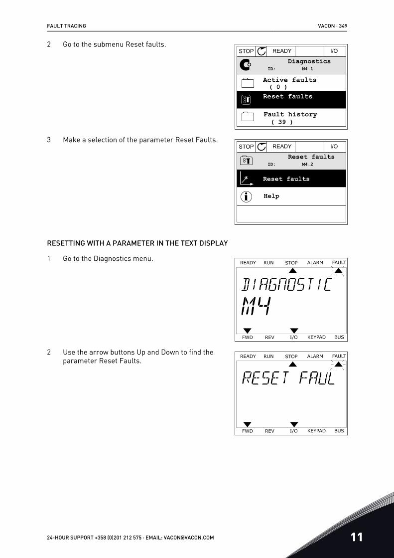
2 Go to the submenu Reset faults.STOP READY I/O
ID: M4.1Diagnostics
( 39 )
Reset faults( 0 )
Active faults
Fault history
3 Make a selection of the parameter Reset Faults.STOP READY I/O
ID: M4.2Reset faults
Help
Reset faults
RESETTING WITH A PARAMETER IN THE TEXT DISPLAY
1 Go to the Diagnostics menu.READY FAULTALARMSTOPRUN
KEYPADI/OREVFWD BUS
2 Use the arrow buttons Up and Down to find theparameter Reset Faults.
READY FAULTALARMSTOPRUN
KEYPADI/OREVFWD BUS
FAULT TRACING VACON · 349
24-HOUR SUPPORT +358 (0)201 212 575 · EMAIL: [email protected] 11

3 Make a selection of the value Yes and push OK.READY FAULTALARMSTOPRUN
KEYPADI/OREVFWD BUS
11.2 FAULT HISTORY
In the Fault history, you can find more data on the faults. There is a maximum number of 40faults in the Fault history.
EXAMINING THE FAULT HISTORY IN THE GRAPHICAL DISPLAY
1 To see more data on a fault, go to Fault history.
Active faults( 0 )
( 39 )
STOP READY I/O
DiagnosticsM4.1ID:
Reset faults
Fault history
2 To examine the data of a fault, push the Arrowbutton Right. STOP READY I/O
External Fault 51Fault old
Fault old
Info old 862537s
External Fault 51
Device removed 39
Fault historyM4.3.3ID:
891384s
871061s
VACON · 350 FAULT TRACING
11 TEL. +358 (0)201 2121 · FAX +358 (0)201 212 205

3 You see the data in a list.STOP READY I/O
Code 39
Source 3
Source 1
ID 380State Info oldDate 7.12.2009Time 04:46:33Operating time 862537s
Source 2
Fault historyM4.3.3.2ID:
EXAMINING THE FAULT HISTORY IN THE TEXT DISPLAY
1 Push OK to go to Fault history.READY FAULTALARMSTOPRUN
KEYPAD1/OREVFWD BUS
2 To examine the data of a fault, push OK again.READY FAULTALARMSTOPRUN
KEYPAD1/OREVFWD BUS
FAULT TRACING VACON · 351
24-HOUR SUPPORT +358 (0)201 212 575 · EMAIL: [email protected] 11

3 Use the arrow button down to examine all the data.READY FAULTALARMSTOPRUN
KEYPAD1/OREVFWD BUS
READY FAULTALARMSTOPRUN
KEYPAD1/OREVFWD BUS
READY FAULTALARMSTOPRUN
KEYPAD1/OREVFWD BUS
VACON · 352 FAULT TRACING
11 TEL. +358 (0)201 2121 · FAX +358 (0)201 212 205

11.3 FAULT CODES
Faultcode Fault ID Fault name Possible cause How to correct the fault
1 1 Overcurrent (hard-ware fault)
There is too high a current(>4*I H) in the motor cable.Its cause can be 1 of these.
• a sudden heavy loadincrease
• a short circuit in themotor cables
• the motor is not thecorrect type
• the parameter settingsare not properly made
Do a check of the loading.Do a check of the motor.Do a check of the cables and con-nections.Make an identification run.Set the acceleration time longer(P3.4.1.2 and P3.4.2.2).
2 Overcurrent (softwarefault)
2 10 Overvoltage (hard-ware fault)
The DC-link voltage ishigher than the limits.
• the deceleration time istoo short
• high overvoltage spikesin the supply
Set the deceleration time longer(P3.4.1.3 and P3.4.2.3).Activate the overvoltage controller.Do a check of the input voltage.11 Overvoltage (software
fault)
3 20 Earth fault (hardwarefault)
The measurement of cur-rent tells that the sum of themotor phase current is not0.
• an insulation malfunc-tion in the cables or themotor
• a filter (du/dt, sinus)malfunction
Do a check of the motor cables andthe motor.Do a check of the filters.
21 Earth fault (softwarefault)
5 40 Charging switch The charging switch isclosed and the feedbackinformation is OPEN.
• operation malfunction• defective component
Reset the fault and restart thedrive.Do a check of the feedback signaland the cable connection betweenthe control board and the powerboard.If the fault occurs again, askinstructions from the distributornear to you.
7 60 Saturation• Defective IGBT• de-saturation short cir-
cuit in the IGBT• a short circuit or an
overload in the brakeresistor
This fault cannot be reset from thecontrol panel.Make a power down of the drive.DO NOT RESTART THE DRIVE orCONNECT THE POWER!Ask instructions from the factory.
FAULT TRACING VACON · 353
24-HOUR SUPPORT +358 (0)201 212 575 · EMAIL: [email protected] 11

Faultcode Fault ID Fault name Possible cause How to correct the fault
8 600 System fault There is no communicationbetween the control boardand the power.
Reset the fault and restart thedrive.Download the newest softwarefrom the Vacon website. Updatethe drive with it.If the fault occurs again, askinstructions from the distributornear to you.
601
602 Defective component.Operation malfunction.
603 Defective component.Operation malfunction.The voltage of auxiliarypower in the power unit istoo low.
604 Defective component.Operation malfunction.Output phase voltage doesnot agree to the reference.Feedback fault.
605 Defective component.Operation malfunction.
606 The software of the controlunit is not compatible withthe software of the powerunit.
607 The software version cannotbe read. There is no soft-ware in the power unit.Defective component.Operation malfunction (aproblem in the power boardor the measurement board).
608 A CPU overload.
609 Defective component.Operation malfunction.
Reset the fault and make a powerdown of the drive twice.Download the newest softwarefrom the Vacon website. Updatethe drive with it.
VACON · 354 FAULT TRACING
11 TEL. +358 (0)201 2121 · FAX +358 (0)201 212 205

Faultcode Fault ID Fault name Possible cause How to correct the fault
8 610 System fault Defective component.Operation malfunction.
Reset the fault and restart.Download the newest softwarefrom the Vacon website. Updatethe drive with it.If the fault occurs again, askinstructions from the distributornear to you.
614 Configuration error.Software error.Defective component (adefective control board).Operation malfunction.
647 Defective component.Operation malfunction.
648 Operation malfunction.The system software is notcompatible with the applica-tion.
649 A resource overload.A malfunction in the loading,restoring or saving aparameter.
Load the factory default settings.Download the newest softwarefrom the Vacon website. Updatethe drive with it.
9 80 Undervoltage (fault) The DC link voltage is lowerthan the limits.
• The supply voltage istoo low
• a defective component• a defective input fuse• the external charge
switch is not closed
NOTE!This fault becomes activeonly if the drive is in Runstate.
If there is a temporary supply volt-age break, reset the fault andrestart the drive.Do a check of the supply voltage. Ifthe supply voltage is sufficient,there is an internal fault.Examine the electrical network forfault.Ask instructions from the distribu-tor near to you.
10 91 Input phase• supply voltage mal-
function• a defective fuse or mal-
function in the supplycables
The load must be a mini-mum of 10-20% for thesupervision to work.
Do a check of the supply voltage,the fuses and supply cable, therectifying bridge and the gate con-trol of the thyristor (MR6->).
FAULT TRACING VACON · 355
24-HOUR SUPPORT +358 (0)201 212 575 · EMAIL: [email protected] 11
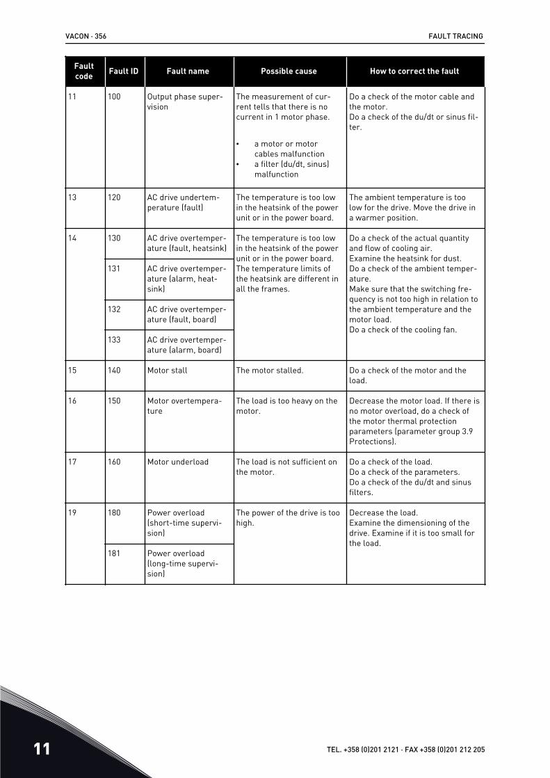
Faultcode Fault ID Fault name Possible cause How to correct the fault
11 100 Output phase super-vision
The measurement of cur-rent tells that there is nocurrent in 1 motor phase.
• a motor or motorcables malfunction
• a filter (du/dt, sinus)malfunction
Do a check of the motor cable andthe motor.Do a check of the du/dt or sinus fil-ter.
13 120 AC drive undertem-perature (fault)
The temperature is too lowin the heatsink of the powerunit or in the power board.
The ambient temperature is toolow for the drive. Move the drive ina warmer position.
14 130 AC drive overtemper-ature (fault, heatsink)
The temperature is too lowin the heatsink of the powerunit or in the power board.The temperature limits ofthe heatsink are different inall the frames.
Do a check of the actual quantityand flow of cooling air.Examine the heatsink for dust.Do a check of the ambient temper-ature.Make sure that the switching fre-quency is not too high in relation tothe ambient temperature and themotor load.Do a check of the cooling fan.
131 AC drive overtemper-ature (alarm, heat-sink)
132 AC drive overtemper-ature (fault, board)
133 AC drive overtemper-ature (alarm, board)
15 140 Motor stall The motor stalled. Do a check of the motor and theload.
16 150 Motor overtempera-ture
The load is too heavy on themotor.
Decrease the motor load. If there isno motor overload, do a check ofthe motor thermal protectionparameters (parameter group 3.9Protections).
17 160 Motor underload The load is not sufficient onthe motor.
Do a check of the load.Do a check of the parameters.Do a check of the du/dt and sinusfilters.
19 180 Power overload(short-time supervi-sion)
The power of the drive is toohigh.
Decrease the load.Examine the dimensioning of thedrive. Examine if it is too small forthe load.
181 Power overload(long-time supervi-sion)
VACON · 356 FAULT TRACING
11 TEL. +358 (0)201 2121 · FAX +358 (0)201 212 205

Faultcode Fault ID Fault name Possible cause How to correct the fault
25 240 Motor control fault This fault is available only ifyou use a customer-specificapplication. A malfunction inthe start angle identifica-tion.
• The rotor moves duringidentification.
• The new angle does notagree with the oldvalue.
Reset the fault and restart thedrive.Increase the identification current.See the fault history source formore information.
241
26 250 Startup prevented It is not possible to do astartup of the drive. Whenthe Run request is ON, anew software (a firmware oran application), a parametersetting or other file thateffects the operation of thedrive, is loaded to the drive.
Reset the fault and stop the drive.Load the software and start thedrive.
29 280 Atex thermistor The ATEX thermistor tellsthat there is an overtemper-ature.
Reset the fault. Do a check of thethermistor and its connections.
FAULT TRACING VACON · 357
24-HOUR SUPPORT +358 (0)201 212 575 · EMAIL: [email protected] 11

Faultcode Fault ID Fault name Possible cause How to correct the fault
30 290 Safe Off The safe off signal A doesnot let you to set the drive tothe READY state.
Reset the fault and restart thedrive.Do a check of the signals from thecontrol board to the power unit andthe D connector.291 Safe Off The safe off signal B does
not let you to set the drive tothe READY state.
500 Safety configuration The safety configurationswitch was installed.
Remove the safety configurationswitch from the control board.
501 Safety configuration There are too many STOoption boards. It is possibleto have only 1.
Keep 1 of the STO option boards.Remove the others. See the safetymanual.
502 Safety configuration The STO option board wasinstalled in an incorrect slot.
Put the STO option board into thecorrect slot. See the safety man-ual.
503 Safety configuration There is no safety configura-tion switch on the controlboard.
Install the safety configurationswitch on the control board. Seethe safety manual.
504 Safety configuration The safety configurationswitch was installed incor-rectly on the control board.
Install the safety configurationswitch into the correct position onthe control board. See the safetymanual.
505 Safety configuration The safety configurationswitch was installed incor-rectly on the STO optionboard.
Do a check of the installation of thesafety configuration switch on theSTO option board. See the safetymanual.
506 Safety configuration There is no communicationwith the STO option board.
Do a check of the installation of theSTO option board. See the safetymanual.
507 Safety configuration The STO option board is notcompatible with the hard-ware.
Reset the drive and restart it. If thefault occurs again, ask instructionsfrom your nearest distributor.
30 520 Safety diagnostics The STO inputs have a dif-ferent status.
Do a check of the external safetyswitch. Do a check of the inputconnection and cable of the safetyswitch.Reset the drive and restart.If the fault occurs again, askinstructions from your nearest dis-tributor.
30 521 Safety diagnostics A malfunction in the ATEXthermistor diagnostic. Thereis no connection in the ATEXthermistor input.
Reset the drive and restart.If the fault occurs again, changethe option board.
VACON · 358 FAULT TRACING
11 TEL. +358 (0)201 2121 · FAX +358 (0)201 212 205

Faultcode Fault ID Fault name Possible cause How to correct the fault
30 522 Safety diagnostics A short circuit in the con-nection of the ATEX ther-mistor input.
Do a check of the ATEX thermistorinput connection.Do a check of the external ATEXconnection.Do a check of the external ATEXthermistor.
30 530 Safe torque off An emergency stop wasconnected or some otherSTO operation was activa-ted.
When the STO function is activated,the drive is in safe state.
32 311 Fan cooling The fan speed does notagree to the speed refer-ence accurately, but thedrive operates correctly.This fault shows only in theMR7 and in the drives thatlarger than MR7.
Reset the fault and restart thedrive. Clean or replace the fan.
312 Fan cooling The fan life time (that is,50,000 h) is complete.
Replace the fan and reset the lifetime counter of the fan.
33 320 Fire mode enabled The Fire mode of the drive isenabled. The protections ofthe drive are not used.This alarm is reset automat-ically when Fire mode is dis-abled.
Do a check of the parameter set-tings and the signals. Some of theprotections of the drive are disa-bled.
37 361 Device changed(same type)
The power unit wasreplaced by a new one thathas the same size. Thedevice is ready to be used.The parameters are availa-ble in the drive.
Reset the fault.The drive reboots after you resetthe fault.
362 Device changed(same type)
The option board in slot Bwas replaced by a new onethat you have used before inthe same slot. The device isready to be used.
Reset the fault. The drive starts touse the old parameter settings.
363 Device changed(same type)
The same cause as in ID362,but refers to Slot C.
364 Device changed(same type)
The same cause as in ID362,but refers to Slot D.
365 Device changed(same type)
The same cause as in ID362,but refers to Slot E.
FAULT TRACING VACON · 359
24-HOUR SUPPORT +358 (0)201 212 575 · EMAIL: [email protected] 11

Faultcode Fault ID Fault name Possible cause How to correct the fault
38 372 Device added (sametype)
An option board was put intoslot B. You have used theoption board before in thesame slot. The device isready to be used.
The device is ready to be used. Thedrive starts to use the old parame-ter settings.
373 Device added (sametype)
The same cause as in ID372,but refers to Slot C.
374 Device added (sametype)
The same cause as in ID372,but refers to Slot D.
375 Device added (sametype)
The same cause as in ID372,but refers to Slot E.
39 382 Device removed An option board wasremoved from slot A or B.
The device is not available. Resetthe fault.
383 Device removed The same cause as in ID380,but refers to Slot C
384 Device removed The same cause as in ID380,but refers to Slot D
385 Device removed The same cause as in ID380,but refers to Slot E
40 390 Device unknown An unknown device wasconnected (the power unit/option board)
The device is not available. If thefault occurs again, ask instructionsfrom your nearest distributor.
41 400 IGBT temperature The calculated IGBT tem-perature is too high.
• the motor load is toohigh
• the ambient tempera-ture is too high
• hardware malfunction
Do a check of the parameter set-tings.Examine the actual quantity andflow of cooling air.Do a check of the ambient temper-ature.Examine the heatsink for dust.Make sure that the switching fre-quency is not too high in relation tothe ambient temperature and themotor load.Do a check of the cooling fan.Make an identification run.
VACON · 360 FAULT TRACING
11 TEL. +358 (0)201 2121 · FAX +358 (0)201 212 205

Faultcode Fault ID Fault name Possible cause How to correct the fault
44 431 Device changed (dif-ferent type)
There is a new power unit ofa different type. Parametersare not available in the set-tings.
Reset the fault.The drive reboots after you resetthe fault.Set the power unit parametersagain.
433 Device changed (dif-ferent type)
The option board in slot Cwas replaced by a new onethat you have not usedbefore in the same slot. Noparameter settings aresaved.
Reset the fault. Set the optionboard parameters again.
434 Device changed (dif-ferent type)
The same cause as in ID433,but refers to Slot D.
435 Device changed (dif-ferent type)
The same cause as in ID433,but refers to Slot D.
45 441 Device added (differ-ent type)
There is a new power unit ofa different type. Parametersare not available in the set-tings.
Reset the fault.The drive reboots after you resetthe fault.Set the power unit parametersagain.
443 Device added (differ-ent type)
A new option board, that youhave not used before in thesame slot, was put in slot C.No parameter settings aresaved.
Set the option board parametersagain.
444 Device added (differ-ent type)
The same cause as in ID443,but refers to Slot D.
445 Device added (differ-ent type)
The same cause as in ID443,but refers to Slot E.
46 662 Real Time Clock The voltage of the RTC bat-tery is low.
Replace the battery.
47 663 Software updated The software of the drivewas updated, the full soft-ware package or an applica-tion.
No steps are necessary.
50 1050 AI low fault 1 or more of the availableanalogue input signals isbelow 50% of the minimumsignal range.A control cable is defectiveor loose.A malfunction in a signalsource.
Replace the defective parts.Do a check of the analogue inputcircuit.Make sure that parameter AI1 Sig-nal Range is set correctly.
FAULT TRACING VACON · 361
24-HOUR SUPPORT +358 (0)201 212 575 · EMAIL: [email protected] 11

Faultcode Fault ID Fault name Possible cause How to correct the fault
51 1051 Device external fault The digital input signal thatis set with parameterP3.5.1.11 or P3.5.1.12 wasactivated.
This is a user-specified fault.Do a check of the digital inputs andschematics.
52 1052 Keypad communica-tion fault
The connection between thecontrol panel and the driveis defective.
Do a check of the control panelconnection and the control panelcable if you have it.1352
53 1053 Fieldbus communica-tion fault
The data connectionbetween the fieldbus masterand the fieldbus board isdefective.
Do a check of the installation andfieldbus master.
54 1354 Slot A fault A defective option board orslot
Do a check of the board and theslot.Ask instructions from your nearestdistributor.
1454 Slot B fault
1554 Slot C fault
1654 Slot D fault
1754 Slot E fault
57 1057 Identification There was a failure in theidentification run.
Make sure that the motor is con-nected to the drive.Make sure that there is no load onthe motor shaft.Make sure that the start commandis not removed before the identifi-cation run is complete.
63 1063 Quick Stop fault The Quick stop function isactivated
Find the cause for the quick stopactivation. After you find it, correctit. Reset the fault and restart thedrive.See parameter P3.5.1.26 and thequick stop parameters.
1363 Quick Stop alarm
65 1065 PC communicationfault
The data connectionbetween the PC and thedrive is defective
Do a check of the installation,cable and terminals between thePC and the drive.
66 1366 Thermistor input 1fault
The motor temperatureincreased.
Do a check of the motor coolingand the load.Do a check of the thermistor con-nection.If the thermistor input is not used,you have to short-circuit it.Ask instructions from your nearestdistributor.
1466 Thermistor input 2fault
1566 Thermistor input 3fault
VACON · 362 FAULT TRACING
11 TEL. +358 (0)201 2121 · FAX +358 (0)201 212 205

Faultcode Fault ID Fault name Possible cause How to correct the fault
68 1301 Maintenance counter1 alarm
The value of the mainte-nance counter is higher thanthe alarm limit.
Do the necessary maintenance.Reset the counter. See parameterB3.16.4 or P3.5.1.40.
1302 Maintenance counter1 fault
The value of the mainte-nance counter is higher thanthe fault limit.
1303 Maintenance counter2 alarm
The value of the mainte-nance counter is higher thanthe alarm limit.
1304 Maintenance counter2 fault
The value of the mainte-nance counter is higher thanthe fault limit.
69 1310 Fieldbus communica-tion fault
The ID number that is usedto map the values to Field-bus Process Data Out is notvalid.
Do a check of the parameters inthe Fieldbus Data Mapping menu.
1311 It is not possible to convert 1or more values for FieldbusProcess Data Out.
The type of the value is not speci-fied. Do a check of the parametersin the Fieldbus Data Mappingmenu.
1312 There is an overflow whenthe values for FieldbusProcess Data Out (16-bit)are mapped and converted.
Do a check of the parameters inthe Fieldbus Data Mapping menu.
76 1076 Start prevented The start command isblocked to prevent the acci-dental rotation of the motorduring the first power-up.
Reset the drive to start the correctoperation. The parameter settingstell if it is necessary to restart thedrive.
77 1077 >5 connections There are more than 5active fieldbus or PC toolconnections. You can useonly 5 connections at thesame time.
Keep 5 active connections. Removethe other connections.
100 1100 Soft fill timeout There is a timeout in theSoft fill function in the PIDcontroller. The drive did notgo to the process value inthe time limit.A pipe that broke can be thecause.
Do a check of the process.Do a check of the parameters inthe menu M3.13.8.
FAULT TRACING VACON · 363
24-HOUR SUPPORT +358 (0)201 212 575 · EMAIL: [email protected] 11

Faultcode Fault ID Fault name Possible cause How to correct the fault
101 1101 Feedback supervisionfault (PID1)
The PID controller: the feed-back value is not in thesupervision limits (P3.13.6.2and P3.13.6.3) and the delay(P3.13.6.4), if you set thedelay.
Do a check of the process.Do a check of the parameter set-tings, the supervision limits andthe delay.
105 1105 Feedback supervisionfault (ExtPID)
The external PID controller:the feedback value is not inthe supervision limits(P3.14.4.2 and P3.14.4.3)and the delay (P3.14.4.4), ifyou set the delay.
109 1109 Input pressure super-vision
The supervision signal of theinput pressure (P3.13.9.2) islower than the alarm limit(P3.13.9.7).
Do a check of the process.Do a check of the parameters inmenu M3.13.9.Do a check of the input pressuresensor and connections.
1409 The supervision signal of theinput pressure (P3.13.9.2) islower than the fault limit(P3.13.9.8).
111 1315 Temperature fault 1 1 or more of the tempera-ture input signals (set inP3.9.6.1) is higher than thealarm limit (P3.9.6.2).
Find the cause of the temperaturerise.Do a check of the temperaturesensor and connections.If no sensor is connected, makesure that the temperature input ishardwired.See the option board manual formore information.
1316 1 or more of the tempera-ture input signals (set inP3.9.6.1) is higher than thefault limit (P3.9.6.3).
112 1317 Temperature fault 2 1 or more of the tempera-ture input signals (set inP3.9.6.5) is higher than thefault limit (P3.9.6.6).
1318 1 or more of the tempera-ture input signals (set inP3.9.6.5) is higher than thefault limit (P3.9.6.7).
113 1113 Pump runnng time In the Multipump system, 1or more of the pump run-time counters is above auser-specified alarm limit.
Do the necessary maintenanceactions, reset the runtime counterand reset the alarm. See Pumprunning time counters.
113 1313 Pump runnng time In the Multipump system, 1or more of the pump run-time counters is above auser-specified alarm limit
Do the necessary maintenanceactions, reset the runtime counterand reset the alarm. See Pumprunning time counters.
VACON · 364 FAULT TRACING
11 TEL. +358 (0)201 2121 · FAX +358 (0)201 212 205

Faultcode Fault ID Fault name Possible cause How to correct the fault
300 700 Unsupported The application is not com-patible (it is unsupported).
Replace the application.
701 The option board or the slotis not compatible (it isunsupported).
Remove the option board.
FAULT TRACING VACON · 365
24-HOUR SUPPORT +358 (0)201 212 575 · EMAIL: [email protected] 11

12 APPENDIX 112.1 THE DEFAULT VALUES OF PARAMETERS IN THE DIFFERENT
APPLICATIONS
The explanation of symbols in the tableA = Standard applicationB = HVAC applicationC = PID control applicationD = Multipump (single drive) applicationE = Multipump (multidrive) application
VACON · 366 APPENDIX 1
12 TEL. +358 (0)201 2121 · FAX +358 (0)201 212 205

Table 117: The default values of parameters in the different applications
Index Parameter Default Unit ID Description
A B C D E
P3.2.1 Remote ControlPlace
0 0 0 0 0 172 0 = I/O Control
P3.2.2 Local/Remote 0 0 0 0 0 2110 = Remote
P3.2.6 I/O A Logic 2 2 2 0 0 300Forw-Back2 = Forw-Back(edge)
P3.2.7 I/O B Logic 2 2 2 2 2 3632 = Forw-Back(edge)
P3.3.1.5 I/O A ReferenceSelection
6 6 7 7 7 1176 = AI1 + AI27 = PID
P3.3.1.6 I/O B ReferenceSelection
4 4 4 4 4 1314 = AI1
P3.3.1.7 Keypad Refer-ence Selection
2 2 2 2 2 1212 = Keypad Ref-erence
P3.3.1.10 Fieldbus Refer-ence Selection
3 3 3 3 3 1223 = Fieldbus Ref-erence
P3.3.3.1 Preset Fre-quency Mode
0 0 0 0 0 1820 = Binary Coded
P3.3.3.3 Preset Fre-quency 1
10.0 10.0 10.0 10.0 10.0 Hz 105
P3.3.3.4 Preset Fre-quency 2
15.0 15.0 15.0 15.0 15.0 Hz 106
P3.3.3.5 Preset Fre-quency 3
20.0 20.0 20.0 20.0 20.0 Hz 126
P3.3.6.1 Activate Flush-ing Reference
0 0 0 0 101 532
APPENDIX 1 VACON · 367
24-HOUR SUPPORT +358 (0)201 212 575 · EMAIL: [email protected] 12
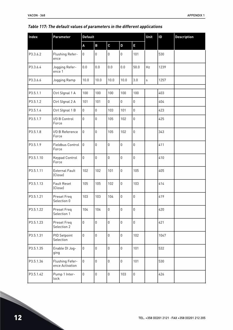
Table 117: The default values of parameters in the different applications
Index Parameter Default Unit ID Description
A B C D E
P3.3.6.2 Flushing Refer-ence
0 0 0 0 101 530
P3.3.6.4 Jogging Refer-ence 1
0.0 0.0 0.0 0.0 50.0 Hz 1239
P3.3.6.6 Jogging Ramp 10.0 10.0 10.0 10.0 3.0 s 1257
P3.5.1.1 Ctrl SIgnal 1 A 100 100 100 100 100 403
P3.5.1.2 Ctrl SIgnal 2 A 101 101 0 0 0 404
P3.5.1.4 Ctrl SIgnal 1 B 0 0 103 101 0 423
P3.5.1.7 I/O B ControlForce
0 0 105 102 0 425
P3.5.1.8 I/O B ReferenceForce
0 0 105 102 0 343
P3.5.1.9 Fieldbus ControlForce
0 0 0 0 0 411
P3.5.1.10 Keypad ControlForce
0 0 0 0 0 410
P3.5.1.11 External Fault(Close)
102 102 101 0 105 405
P3.5.1.13 Fault Reset(Close)
105 105 102 0 103 414
P3.5.1.21 Preset FreqSelection 0
103 103 104 0 0 419
P3.5.1.22 Preset FreqSelection 1
104 104 0 0 0 420
P3.5.1.23 Preset FreqSelection 2
0 0 0 0 0 421
P3.5.1.31 PID SetpointSelection
0 0 0 0 102 1047
P3.5.1.35 Enable DI Jog-ging
0 0 0 0 101 532
P3.5.1.36 Flushing Fefer-ence Activation
0 0 0 0 101 530
P3.5.1.42 Pump 1 Inter-lock
0 0 0 103 0 426
VACON · 368 APPENDIX 1
12 TEL. +358 (0)201 2121 · FAX +358 (0)201 212 205

Table 117: The default values of parameters in the different applications
Index Parameter Default Unit ID Description
A B C D E
P3.5.1.43 Pump 2 Inter-lock
0 0 0 104 0 427
P3.5.1.44 Pump 3 Inter-lock
0 0 0 105 0 428
P3.5.2.1.1 AI1 SignalSelection
100 100 100 100 100 377
P3.5.2.1.2 AI1 Filter Time 0.1 0.1 0.1 0.1 0.1 s 378
P3.5.2.1.3 AI1 SignalRange
0 0 0 0 0 3790 = 0…10V / 0…20mA
P3.5.2.1.4 AI1 Custom Min 0.0 0.0 0.0 0.0 0.0 380
P3.5.2.1.5 AI1 Custom Max 100.0 100.0 100.0 100.0 100.0 381
P3.5.2.1.6 AI1 Signal Inver-sion
0 0 0 0 0 387
P3.5.2.2.1 AI2 SignalSelection
101 101 101 101 101 388
P3.5.2.2.2 AI2 Filter Time 0.1 0.1 0.1 0.1 0.1 s 389
P3.5.2.2.3 AI2 SignalRange
1 1 1 1 1 3901 = 2…10V / 4…20mA
P3.5.2.2.4 AI2 Custom Min 0.0 0.0 0.0 0.0 0.0 391
P3.5.2.2.5 AI2 Custom Max 100.0 100.0 100.0 100.0 100.0 392
P3.5.2.2.6 AI2 Signal Inver-sion
0 0 0 0 0 398
P3.5.3.2.1 RO1 Function 2 2 2 49 2 110012 = Run
P3.5.3.2.4 RO2 Function 3 3 3 50 3 110043 = Fault
P3.5.3.2.7 RO3 Function 1 1 1 51 1 110071 = Ready
APPENDIX 1 VACON · 369
24-HOUR SUPPORT +358 (0)201 212 575 · EMAIL: [email protected] 12

Table 117: The default values of parameters in the different applications
Index Parameter Default Unit ID Description
A B C D E
P3.5.4.1.1 AO1 Function 2 2 2 2 2 100502 = Output Fre-quency
P3.5.4.1.2 AO1 Filter Time 1.0 1.0 1.0 1.0 1.0 s 10051
P3.5.4.1.3 AO1 Min Signal 0 0 0 0 0 10052
P3.5.4.1.4 AO1 Min Scale 0.0 0.0 0.0 0.0 0.0 10053
P3.5.4.1.5 AO1 Max Scale 0.0 0.0 0.0 0.0 0.0 10054
P3.10.1 Automatic Reset 0 0 1 1 1 7310 = Disabled1 = Enabled
P3.13.2.5 PID SetpointSelection
0 0 0 0 102 1047
P3.13.2.6 PID SetpointSource 1
- - 1 1 1 3321 = Keypad Set-point 1
P3.13.2.10 PID SetpointSource 2
- - - - 2 4312 = Keypad Set-point 2
P3.13.3.1 PID FeedbackFunction
- - 1 1 1 333
P3.13.3.3 PID FeedbackSource
- - 2 2 2 334
P3.15.1 MultipumpMode
- - - 0 2 1785
P3.15.2 Number ofPumps
1 1 1 3 3 1001
P3.15.5 Pump Interlock-ing
- - - 1 1 1032
P3.15.6 Autochange - - - 1 1 1027
P3.15.7 AutochangedPumps
- - - 1 1 1028
VACON · 370 APPENDIX 1
12 TEL. +358 (0)201 2121 · FAX +358 (0)201 212 205

Table 117: The default values of parameters in the different applications
Index Parameter Default Unit ID Description
A B C D E
P3.15.8 AutochangeInterval
- - - 48.0 48.0 1029
P3.15.11 AutochangeFrequency Limit
- - - 25.0 50.0 Hz 1031
P3.15.12 AutochangePump Limit
- - - 1 3 1030
P3.15.13 Bandwidth - - - 10.0 10.0 % 1097
P3.15.14 BandwidthDelay
- - - 10 10 s 1098
P3.15.15 Constant Pro-duction Speed
- - - - 100.0 % 1513
P3.15.16 Running PumpsLimit
- - - 3 3 1187
P5.7.1 Timeout time 5 5 5 5 5 min 804
P5.7.2 Default Page 4 5 4 4 4 23184 = Multimonitor
APPENDIX 1 VACON · 371
24-HOUR SUPPORT +358 (0)201 212 575 · EMAIL: [email protected] 12


Document ID:
Rev. D
Manual authoring:[email protected]
Vacon Plc.Runsorintie 765380 VaasaFinland
Subject to change without prior notice© 2014 Vacon Plc. Sales code: DOC-APP100FLOW+DLUK
Find your nearest Vacon office on the Internet at:
www.vacon.com