Embed Size (px)
Citation preview

V.8 ENGINE
Blown Cylinder Head Gasket DiagnosisCamshaft and BearingsConnecting RodsConnecting Rod and Piston AssembliesCrankshaftCylinder BlockCylinder Head and GasketCylinder Head CoverCylinder Head ReconditioningCylinder Leakage TestEngine InstallationEngine MountingEngine RemovalExhaust ManifoldFlywheel and Starter Ring GearGeneralHydraulic Valve Tappets .Identification
Assenibly
PageiB-lO1B-231B-291B-2918-361B-271B-i518-12lB-i 61B-lOlB-li1B-5
‘B-il1 B-i 51B-38lB-i
1B-18lB-i
Intake ManifoldLubrication SystemOil FilterOil PanOil PumpPistonsRear Main Bearing Oil Seal .
Rocker Arm AssemblyService DiagnosisShort Engine AssemblySpecial ToolsSpecificationsTiming ChainTiming Case CoverValve Stem Oil DeflectorValve SpringValve Stem-to-Guide Clearance.
Page.JB-14
18-2iB-251 B-251B-251 B-33
_______
.1B-26
.iB-12.18-6
.18-39
.iB-4318-3918-21
.1B-20
.1B-13
.1B-i3.18-17
Vibration Damper 18-19
GENERAL
The 304, 360, and 401 CID enginesare 90-degreeV-8designsincorporatingoverheadvalves. The 304 CID engines CJ Model only operateONLY on unleadedgasoline. The cylindersarenumberedfrom front to rear: 1-3-5-7 on the left bank and2-4-6-8 on the right bankwithcylinder firing order 1.8-4-3-6-5-7-2.
The crankshaft, supported by five two-piece mainbearings, rotates in a counterclockwisedirection asviewedfrom therear. The camshaftis supportedby fiveone-piece,line-boredbearings.
Bridged pivot assembliescontrol movementof intakeand exhaustrocker arms that are paired[ by cylindersfig. lB-i and 1B-2.
Serviceproceduresfor all V-8 enginesare essentiallythe same.
IdentificationThe cubic-inchdisplacementof all V-8 enginesis cast
into eachside of the cylinderblock. Thesenumbersarelocatedbetweenthe enginemountingbracketbosses.
Build Date CodeThe engine Build Date Code is located on a tag at
tachedto the right bankcylinderheadcoverfig. 1B-3.The codenumbersidentify the year, month, and day
that the enginewasbuilt. The code letter identifies thecubic inch displacement,carburetor type, and compressionratio.
Example: 1 05 H 13
The examplecodeidentifies a 304 CID with 2V carburetor and8.4:1 compressionratio built on May 13, 1977.
lB-i
41920
Fiig. lB-i Sectional View of V-8 Engine Assembly

IB-2 V-8 ENGINE
Engine Build Date Code Explanation
LetterCode
CID CarburetorCompression
Ratio
HNPZ
304360360401
2V2V4V4V
8.4:18.25:18.25:18.25:1
1stCharacter
Year
2nd and 3rdCharactersMonth
4thCharacter
Engine Type
5th and 6thCharacters
Day
9- 19761 --1977
01 -12 H,N,P,V,orZ 01-31
60265
Oversize or Undersize Components
It is sometimesnecessaryto machineall cylinderboresto 0.010-inchoversize,all crankshaftmain bearingjournals,all connectingrod journalsto 0.010-inchundersize, or all camshaftbearingbores 0.010-inchoversize.These engines have a single or double letter codestampedadjacentto the Build Date Codeon the tagattached to the right bank cylinder head cover. Theletters arecodedas follows:
Oversize or Undersize Letter Code
Single Letter B cylinder bore 0.010-inch oversize
Single Letter M main bearings 0.010-undersize
Single Letter F connecting rod bearings 0.010-inchundersize
Double Letters PM main and connecting rod bearings0.010-inch undersize
Single Letter C camshaft bearing bores 0.01 0-inchoversize
LUBRICATION SYSTEM
60258
A gear-type, positive displacementoil pump is incorporatedin the timing casecover.A cavity in thecoverforms the body of the pump while drive andidler gearsrotate within the cavity. The drive gear shaft is drivenby the distributor.
The oil pump cover seals the end of the oil pumpcavity and also servesas a mount for the oil filter. Theoil pressurerelief valve assemblyis locatedin the oilpumpcover fig. 1B-4.
Oil is drawn from the sump area of the oil panthrough a tube and screenassemblyto a horizontal oil
vs
Fig. 1B-2 Typical V-8 Engine Assembly
60487
Fig. 1 B-3 Build Date Code Location V-8

V-8 ENGINE 1B-3
OIL PRESSURE RELIEFVALVE ASSEMBLY
OIL FILTER BYPASS
ANTI-LOCKRELIEFPORTRE LI EVESTO PUMPINLETPASSAGE
PUMPoUTLETTO OIL ANTI-LOCK
FILTER RELIEF PORTALLOWS OILWHICH HASBEEN TRAPPEDBEHIND POPPETVALVE TOBLEED OFF
Fig. 1B-5 Oil Pump Passages
Fig. 18-4 Oil Pump and Filter Assembly41923
gallery located at the lower right side of the engineblock. A passagein the timing case cover channelsoilinto the oil pump. Pressureis developed when oil isdriven betweenthe gearsand pumpbody.
The oil is forced from the pump through a passageinthe oil pumpcover to the oil filter fig. iB..5.
The oil passesthroughthefiltering elementsandto anoutlet passagein theoil pump cover.From the oil pumpcover passage,the oil entersan adioiningpassagein thetiming case cover and then is channeledinto a gallerywhich extendsup the left front of the cylinder block.This gallery channelsoil directly to the right main oilgallery which intersectswith a short passagethatchannels oil to the left main oil gallery.
The left andright main oil galleriesextendthe lengthof the cylinderblock. The left oil gallery channelsoil toeach hydraulic tappet on the left bank. The right oil
gallery channelsoil to eachhydraulic tappeton the rightbank. In addition, five passagesextend down from theright oil gallery to eachcamshaftbearingand on to eachuppermain bearinginsert. The crankshaftis drilled toallow oil to flow from each main journal to adjacentconnectingrod journals. A squirt hole in each connecting rod bearingcap distributes oil to the cylinderwalls, pistonsandpistonpins as the crankshaftrotates.
A small passagewithin the front camshaft bearingjournal channelsoil through the camshaftsprockettothe timing chain cover area where the chain andsprocketsthrow off oil to lubricatethe distributorgearsand fuel pump eccentric.This oil returnsto the oil panby passingunderthe front main bearingcap.
The oil supply for the rockerarm assembliesis metered through the hydraulic valve tappetsand routedthroughhollow pushrodsto a holen thepushrod endofthe correspondingrocker arm. This oil lubricatesthevalve train, thenreturnsto the oil panthrough channelsat bothendsof the cylinder headfig. 1B-6.
ri
TIMINGCASE
OIL PUMPCAVITY OIL
FILTER
IDLER SHAFT
FILTER OUTLETFILTERED OILTO CYLINDERBLOCK
IDLER
PRESSURERELIEFVALVEIN LET
DRIVE SHAFTAND GEAR
GASKET
COVER
OIL FILTERADAPTER
VALVEASSEMBLY
60266

18-4 V-8 ENGINE ri
70001
Fig. 1 B-6 Lubrication System

vu V-8 ENGINE 1B-5
ENGINE MOUNTING
Resilient rubber mounting cushions support the engine and transmissionat threepoints. A cushion is locatedat eachside on the centerlineof the enginewiththe rearsupportedby a cushion betweenthe transmission extensionhousingandthe rear supportcrossmember fig. 1B-7.
Removal or replacementof any cushwnmay be accomplishedby supportingthe weight of the engine ortransmissionin the areaof the cushion.
If necessaryengine holdingin figure iB-8.
to remove the front enginemounts,anfixture may be fabricatedas illustrated
FIg. 18-7 TypIcal Engine Mountlng-V-8 Engine
AJ41 950
FRONTCUSHIONS
RESTRICTORPLATES
J42579
9/16 - 12 NUTS 2
UPPER
9/16-12
2x2x6 HARDWOOD BLOCK
BLOCK
NOTE: DIMENSIONS ARE IN INCHES
INSTALL IN V.8 INTAKEMANIFOLD - ADJACENTTO OIL FILL PIPE.
FIg. 1 B-8 EngIne Holding Fixture

18-6 V-8 ENGINE vu
Service Diagnosis
Condition PossibleCause Correction
EXTERNAL OIL 1 Fuelpump gasketbrokenor 1 Replacegasket.LEAKS improperly seated.
2 Cylinder headcover gasket 2 Replacegasketor reseal;checkbrokenor improperly seated. cylinder headcover gasketflange
andcylinder headgasketsurfacefor distortion.
3 Oil filter gasketbrokenor 3 Replaceoil filter.improperly seated.
4 Oil panside gasketbrokenor 4 Replacegasket;checkoil panimproperly seated. gasketflangefor distortion.
5 Oil panfront oil sealbroken 5 Replaceseal;checktiming caseor improperly seated. cover andoil pansealflange for
distortion.
6 Oil panrear oil sealbroken 6 Replaceseal;checkoil pan rearor improperly seated, oil seal flange;checkrearmain
bearingcapfor cracks,pluggedoil returnchannels,or distortionin sealgroove.
7 Timing casecover oil sealbroken 7 Replaceseal.or improperly seated.
8 Oil pandrain plugloose or 8 Repairasnecessaryandstripped threads, tighten.
9 Rearoil galleryplug loose. 9 Use appropriatesealantongallery plug andtighten.
10 Rearcamshaftplugloose or 10 Seatcamshaftplug or replaceandimproperly seated. seal,asnecessary.
11 Porosity in crankshaftpilot 11 Sealwith RTV Silicone and corebushinghole. plug or replacecrankshaftas
necessary.
EXCESSIVEOIL 1 Oil level too high. 1 Lower oil level to specifications.CONSUMPTION
2 Oil too thin. 2 Replacewith specifiedoil.
3 Valve stemoil deflectorsaredam- 3 Replacevalvestemoil deflectors.aged,missing,or incorrecttype.
4 Valve stemsor valve guidesworn. 4 Checkstem-to-guideclearanceandrepairasnecessary.
5 Piston rings broken,missing. 5 Replacemissingor brokenrings.
60547A

vu - V-8 ENGINE lB-i
Service Diagnosis Continued
Condition PossibleCause Correction
EXCESSIVEOIL 6 Incorrect piston ring gap. 6 Checkring gap,repairasCONSUMPTION necessary.Continued
7 Piston rings sticking or excessive- 7 Checkring side clearance,repairly loosein grooves, asnecessary.
8 Compressionrings installedup- 8 Removeglazefrom cylinderside down. wall andreplacerings.
9 Cylinder walls worn, scored,or 9 Removeglazeor reborecylindersglazed. asnecessary.
10 Piston ring gapsnot staggered. 10 Removeglaze,replacerings, andstaggerring gaps.
11 Blocked or restrictedPCV 11 Inspecthose,flow test PCV, andvalveor hose, repairor replaceasnecessary.
12 Excessivemain or connectingrod 12 Check bearingclearance,repairbearingclearance, asnecessary.
NO OIL PRESSURE 1 Low oiLl level. 1 Add oil to correctlevel.
2 Oil pressuregaugeor sending 2 Refer to Section3, Oil Pressureunit inaccurate. GaugeandSendingUnit Test.
3 Oil pump malfunction. 3 Refer to Oil Pump.
4 Oil pressurerelief valve sticking. 4 Removeand inspectoil pressurerelief valve assembly.
5 Oil passageson pressureside of 5 Inspectoil passagesforpump obstructed. obstructions.
6 Oil pickup screenor tube 6 Replaceoil pickup tube assembly.obstructed[.
7 Loose oil pickup tube. 7 Sealand tighten.
LOW OIL PRESSURE 1 Low oil level. 1 Add oil to correctlevel.
2 Oil pressuregaugeor sendingunit 2 Refer to Section3, Oil Pressureinaccurate. GaugeandSendingUnit Test.
3 Oil excessivelythin dueto dilu- 3 Drain andrefill crankcasewithtion, poorquality, or improper recommendedoil.grade.
4 Oil pressurerelief spring weak 4 Removeand inspectoil pressureor sticking. relief valve assembly.
605478

18-8 V-8 ENGINE vu
Service Diagnosis Continued
Condition PossibleCause Correction
LOW OIL PRESSURE 5 Oil pickup tube andscreen 5 Removeand inspectoil pickupContinued assemblyhasrestriction or tube andscreenassembly. Fill
air leak. pickup with lacquerthinner tofind leaks.
6 Oil pump malfunctioning. 6 Inspectandcheckclearances.Referto Oil Pump.
7 Excessivemain,rod, or camshaft 7 Measurebearingclearances,bearingclearance, repairasnecessary.
HIGH OIL PRESSURE 1 Impropergradeoil. 1 Drain andrefill crankcasewithcorrectgradeoil.
2 Oil pressuregaugeor sending 2 Refer to Section3, Oil Pressureunit inaccurate. GaugeandSendingUnit Test.
3 Oil pressurerelief valvesticking 3 Removeand inspectoil pressureclosed, relief valve assembly.
4 Pressurerelief passageor anti- 4 Checkfor restrictionin anti-locklock port restricted, port andrepairasnecessary.
MAIN BEARING 1 Insufficient oil supply. 1 Checkfor low oil level or lowNOISE oil pressure.
2 Main bearingclearanceexcessive. 2 Checkmain bearingclearance,repairasnecessary.Make certainall upperinsertsare installed.
3 Crankshaftend play excessive. 3 Checkendplay, repairasnecessary.
4 Loose flywheel or torque 4 Tighten flywheel or converterconverter, attachingbolts.
5 Looseor damagedvibration 5 Repairasnecessary.damper.
CONNECTINGROD 1 Insufficient oil supply. 1 Checkfor low oil level or lowBEARING NOISE oil pressure.
2 Bearingclearanceexcessiveor 2 Checkclearance,repairasbearingmissing. necessary.
3 Crankshaftconnectingrod 3 Checkjournal measurements,journal out-of-round. repairor replaceas necessary.
4 Misaligned connectingrod. 4 Repairasnecessary.
5 Connectingrod bolts not tight- 5 Tighten bolts to specifiedtorque.enedto proper torque.
60547C

vu
Service Diagnosis Continued
V-8 ENGINE IB-9
Condition PossibleCause Correction
VALVE TRAINNOISE
NOTE: A clicking noise.upon starting the engine.reducingin level anddisappearingaftera shortperiodof time is normal. This noiseis duetoa slight oil leak-downconditioncausedbyvalve spring pressureexertedon the tappets.
1 Piston-to-cylinderwall clearanceexcessive.
2 Cylinder walls excessivelytapered[or out-of-round.
3 Piston ring broken.
4 Loose or seizedpiston pin.
5 Connectingrodsmisaligned.
6 Pistonring side clearanceexcessively loose or tight.
7 Carbonbuild-up on piston isexcessive.
1 Insufficient oil supply.
2 Pushrodsworn, bent or rubbingagainstcylinder head.
3 Rockerarmsor bridged pivotsworn.
4 Dirt or chips in hydraulic tappets.
5 Excessivetappetleak-down.
6 Tappetfaceworn.
7 Broken or cockedvalve springs.
8 Stem-to-guideclearanceexcessive
9 Valve bent.
10 Looserockerarms.
ii Valve seatrunout excessive.
1 Check clearance,repair asnecessary.
2 Check cylinderwall measurements,repair asnecessary.
Replacering. Checkpiston lands.
Checkpiston-to-pinclearance,repairasnecessary.
5 Checkrod alignment,repair asnecessary.
6 Checkring side clearance,repairasnecessary.
7 Clean carbon from piston.
1 Checkfor:a Low oil level.b Low oil pressure.c Wronghydraulic tappet.d Pluggedoil gallery in block.e Pluggedpushrod.
2 Replaceworn or bent pushrods.Repaircylinder headas necessary.
3 Replaceworn rockerarmsorpivots.
4 Clean tappets.
5 Replacevalve tappet.
6 Replacetappet;checkcorrespondingcamlobe for wear.
7 Properly seatcockedsprings;replacebrokensprings.
8 Checkstem-to-guideclearance,repairasnecessary.
9 Replacevalve.
10 Tighten capscrewsto specifiedtorque. Checkfor stripped threads.
11 Regrindvalve seat/valve.
PISTON NOISE
3
4
60547D

JB-lO V-8 ENGINE
Cylinder Leakage Test Diagnosis
vi
Condition PossibleCause Correction
AIR ESCAPESTHROUGH
1 Intake Valve leaks. 1 Referto Valve ReconditioningunderCylinder Head
CARBURETOR Reconditioning.
AIR ESCAPES 2 ExhaustValve leaks. 2 Refer to Valve ReconditioningTHROUGH underCylinder HeadTAILPIPE Reconditioning.
AIR ESCAPES 3 HeadGasketleaksor crack 3 Removecylinder headTHROUGH in cylinder block, and inspect.RADIATOR
MORE THAN 25% 4 Headgasketleaksor crack 4 Removecylinder headLEAKAGE ON in cylinder block or head and inspect.ADJACENTCYLINDER
betweenadjacentcylinders.
MORE THAN 25%LEAKAGE ANDAIR ESCAPESTHROUGH OIL
5 Stuckor brokenpistonrings;crackedpiston; worn ringsand/orcylinder wall.
5 Inspectfor brokenrings orpiston. Measurering gap andcylinder diameter,taperandout-of-round.
FILLER CAP OPENING ONLY
60527
CYLINDER LEAKAGE TESTSatisfactoryengineperformancedependsupon a me
chanicallysoundengine. In many cases,unsatisfactoryperformanceor rough idle is caused by combustionchamber leakage.A compressiontest alone may notshow this fault. The cylinder leakagetest provides anaccurate meansof testing engine condition. Cylinderleakagetestingwill point out exhaustand intakevalveleaks, leaks betweencylindersor into the water jacket,or othercausesof compressionloss.
1 Check coolant level and fill as required.Do notinstall radiatorcap.
2 Start and run engine until it reachesnormaloperatingtemperature.
3 Removesparkplugs.4 Removeoil filler cap.5 Removeair cleaner.6 Set carburetor fast idle speedscrew on top of
fast idle cam.7 Calibrate tester according to instructions of
manufacturer.
NOTE: Shopair sourcefor testingshouldmaintain 70psi minimum and 200 psi maximum 80 psirecommended.
8 Performtestprocedureon eachcylinderaccording to testermanufacturer’sinstructions.
NOTE: While testing, listen for air escapingthroughcarburetor, tailpipe or oil filler cap opening. Checkforbubblesin radiator coolant.
9 All gauge indications should be even with nomore than 25% leakage.For example:at 80 psi inputpressure,a minimum of 60 psi shouldbe maintainedinthe cylinder. Refer to the Cylinder LeakageTest Diagnosischart.
BLOWN CYLINDER HEAD GASKET DIAGNOSISA blown cylinderheadgasketususallyresultsin a loss
of power, loss of coolant or enginemiss.A blown cylinder headgasketmaydevelopbetweenadjacentcylindersor betweenacylinderand adjacentwaterjacket.
A cylinder headgasketblown betweentwo adjacentcylindersis indicatedby a lossof poweror enginemiss.
A cylinder headgasketblown betweena cylinderandan adjacent water jacket is indicated by foaming ofcoolantor overheatingand lossof coolant.
Replacea blown cylinder headgasketfollowing theproceduresoutlinedin this chapter.
Cylinder-to-Cylinder Leak TestTo determine if the cylinder headgasket is blown
betweeencylinders, perform a compressiontestas outlined underCompressionTest. A cylinder headgasket

‘a V-B ENGINE lB-li
blown betweentwo cylinderswill reult in approximatelya 50-70%reductionin the two affectedcylinders.
Cylinder-to-Water Jacket Leak Test1 Remove radiator cap and start engine. Allow
engineto warm up until thermostatopens.2 If large compressionleak exists,bubblescanbe
seenin coolant.3 If bubblesare riot visible, install radiator pres
suretesterand pressurizesystem. If cylinder is leakinginto waterjacket, needlewill pulsateeverytime cylinderfires.
ENGINE REMOVALThe engineis removedwithout the transmissionand
bell housing.1 On Cherokee,Wagoneer,and Truck models, the
hood must be removed.Mark hinge locations at hoodpanel for alignment during installation. Remove hoodfrom hinges.
2 Removeair cleanerassembly.3 Drain cooling systemand disconnectupperand
lower radiatorhoses.Disconnectheaterhoses.4 If equipped with automatic transmission,dis
connectcooler lines from radiatorandengineassembly.
NOTE: If vehicleis equippedwith 1 radiator shroud, itis necessaryto separatethe shroudfrom the radiator tofacilitate removaland installofiou of the radiator andenginefan.
5 Removeradiator,6 Remove radiator fan. If equippedwith power
steering, remove fluid from pump reservoir and disconnecthoses.
7 If equipped with air conditioning, turn bothservice valves clockwise to the front-seatedposition.Bleedcompressorrefrigerantchargeby slowly looseningservice valve fittings. Remove service valves fromcornpressor.
8 RemoveCruise Commandvacuumservobellowsand mountingbracketas an assemblyif equipped.
9 On Cherokee,Wagoneer,arid Truck modelsremove battery.
10 Disconnectwire harnessfrom engineand moveaside.
11 Disconnectthe following linesif equipped:* Fuel supplyandreturn linesat chassistubing* Vacuumline at powerbrakeunit* Vacuum line for heater damper doors at intake
manifold12 If equipped with automatic transmission,dis
connecttransmissionfiller tube bracket from right cylinder head. Do not remove filler tube from thetransmission.
13 Remove both engine front support cushion-to-frameretainingnuts.
14 Supportweightof enginewith a lifting device.
15 Cn CJ models,removeleft front supportcushionand bracketfrom cylinderblock.
16 On CJ modelsequippedwith manual transmission, removetransfercase shift leverboot, floormat ifequippedLandtransmissionaccesscover.
17 On vehiclesequippedwith automatictransmissions,removeupperbolts securingthe transmissionbellhousingto engine.If equippedwith manual transmission,remove upperbolts securingclutch housingto engine.
18 Disconnectexhaustpipes at exhaustmanifoldsandsupportbracket.
19 Removestartermotor.20 Supporttransmissionwith a floor jack.21 If equipped with automatic transmission,re
move engine adapterplate inspection cover. Mark assembleciposition of converterandflex plateandremovethe converter-to-flexplatecapscrews.
22 Remove remainingbolts securingtransmissionbell housingto engine.If equippedwith manual transmission, remove clutchhousinglower cover andremainingbolts securingclutchhousingto engine.
23 Removeengineby pulling upwardandforward.
CAUTION: if equippedwith power brakes,caremustbe taken to avoid damagingthe powerunit whileremoving the system.
ENGINE INSTALLATION
1 Lower engine slowly into enginecompartmentand align with transmission bellhousing automatictransmissionor clutch housingmanual transmission.On manual transmissions,makecertain clutch shaft isalignedproperlywith splinesof clutch driven plate.
2 Install the transmissionbelihousing-to-enginebolts automatic transmissionor clutch housingmanual transmission. Tighten bolts to specified torqueautomatictransmission:28 foot-pounds;manualtransmission:27 foot-pounds.
3 Remove floor jack which was usedto supporttransmission.
4 If equippedwith automatictransmission,alignmarkspreviously madeon converterandflex plate, install converter-to-flex plate capscrewsand tighten tospecifiedtorque.
5 Install inspection cover automatic transmission or the clutch housing lower cover manualtransmission.
6 Install startermotor.7 On CJ models, install left front supportcushion
and bracket to cylinder block. Tighten bolts to 28 footpoundstorque.
8 Lower engineonto frame supports,and removethe lifting device.
9 Install front support cushion retaining nuts.Tighten nuts to 33 foot-poundstorque.

18-12 V-8 ENGINE
10 Connectexhaustpipesat exhaustmanifolds andsupport bracket.
11 If equippedwith automatic transmission,connect transmissionfiller tube bracket to right cylinderhead.
12 Install batteryif removed.13 Install Cruise Commandvacuumservobellows
andmountingbracket,if removed.14 Connectall wires, lines, linkage, and hosespre
viously disconnectedfrom engine.15 If removed, install air conditioning condenser
andreceiverassembly.16 Connect receiver outlet to the disconnectcou
pling. Connect condenser and evaporator lines tocompressor.
17 Purge compressorof air as outlined in Section13A-Air Conditioning.
CAUTION: Both service valvesmust be open beforeI/ic wi couditioningsystemis operated.
18 If equippedwith power steering,connecthosesand fill pumpreservoirto specifiedlevel.
19 Install radiator fan and tighten the retainingbolts to 18 foot-poundstorque.
20 Install radiator and connect upper and lowerhoses.If equippedwith automatictransmission,connectcoolerlines.
21 Fill cooling systemto specifiedlevel.22 Install air cleanerassembly.23 Start engine. Check all connectionsfor leaks.
Stopengine.24 If removed,install andalign hood assembly.25 If removed, install transmissionaccesscover,
floormat,andtransfercaseshift leverboot.
CYLINDER HEAD COVERAll V-8 enginesusea formed-in-placeRTV room tem
peraturevulcanizingsilicone cylinder headgasket.
Removal1 Removeair cleanerassembly2 Disconnect air delivery hose at air injection
manifold if equipped.3 Left side:
a Disconnetpower brake vacuumhoseat intakemanifold.
equipped.b Disconnect throttle stop solenoid wire if
4 Right side:a Remove Thermostatically Controlled Air
CleanerTAC hot air hose.b Remove heater hose from choke cover
clamp.5 Disconnectsparkplug wires and removeplastic
wire separatorfrom cylinder headcover bracket.6 Removeretainingscrewsandwashers,separate
cylinderheadcover from cylinderhead.
vu
Installation1 Inspectionfor bent or crackedcover and repair
as required.2 Cleancylinderheadcover andcylinderheadgas
ket surfaceof old gasketmaterial.3 Apply a bead of Jeep Gasket-in-a-Tube, or
equivalent, to cylinder head and cylinder head covergasketsurface.
NOTE: If silicone gaskethasnot beenbadly damagedduring removal, it is not necessaryto clean and resealcover completely.UseJeepGasket-in-a-Tubeor equivalent, to repair smallgaps in silicone gasket.
4 Positioncylinderheadcover on engine.5 Install retaining screws and tighten to 50 inch-
poundstorque.
NOTE: Do not overtighten screws as this will crackcylinder headcovers and form gapsin sealer.
6 Connectsparkplug wiresandinstall plastic wireseparatorto cylinderheadcover bracket.
7 Right Side:a Install heaterhose to chokecover clamp.b Install TAC hot air hose.
8 Left Side:a Connectpowerbrake vacuumhoseat intake
manifold.b Connect throttle stop solenoid wire if
equipped.9 Connect air delivery hose to air injection
manifold.10 Install air cleanerassembly
ROCKER ARM ASSEMBLYThe intake and exhaustrocker arms of eachcylinder
pivot on a bridgedpivot assemblywhich is securedto thecylinder headby two capscrewsas shownin figure 1B-9.
Fig. 18-9 Rocker Arm Assembly-V-8 Engine

vu V-8 ENGINE 1B-13
The bridgedpivot maintainscorrectrockerarm-to-valvetip alignment.
The pushrodsare hollow andserveas oil galleriestolubricatethe rockerarm assemblies.
Removal1 Removecylinderheadcover.
NOTE: Keepall parts in thesomeorder and positionasremoved.from engine.
2 Remove rocker arms and bridged pivot assemblies, looseningeachcapscrewa turn at a time to avoidbreakingthe bridge.
3 Removepushrods.
Cleaning and InspectionClean all parts with a good cleaningsolventand use
compressedair to clean the oil passagesin the rockerarms andpushrods.
Inspect the pivot surface of each rocker and pivotassemblyand replaceany part which is scuffed,pitted,or excessivelyworn. Inspect the valvestemcontactsurface of each rocker arm and replace any rocker armwhich is deeplypitted.
Inspect each push rod end for scuffing or excessivewear and replaceas required.It is not norma to find awear patternalong the length of the pushrod. Checkthecylinderheadfor obstruction if this condition exists.
NOTE: If a pushrod iS e.rcessi earn clue to lack ofoil, thepush.rod as well as the match up hydraulic valvetappetand rockerarm must be replaced.
Installation1 Install pushrods.Make certain the bottom end
of eachrod is centeredin the plunger cap of hydraulicvalve tappet.
2 Install rockerarmsandbridgepivot assemblies.3 Install capscrews,tightening eachcapscrewfor
eachbridge assemblya turn at a time to avoid breakingthe bridge. Tighten capscrewsto 19 foot-poundstorque.
4 Resealandinstall cylinderheadcover.5 Install retaining screws and washers.Tighten
screwsto 50 inch-poundstorque.
VALVE SPRING/VALVE STEM OIL DEFLECTORNylon valve stem oil deflectors are installedon each
valvestemto preventthe oil used for rocker arm lubrication from enteringthe combustionchamberthroughthe valve guides. Replaceoil deflectorswhenevervalveservice is performed or if the deflectors becomedeteriorated.
Eachvalve spring is held in placeon the valvestembya retaineranda set of valvelocks. Removevalvelocks bycompressingthe valve spring.
Valve springsand oil deflectorscanbe removedwithout removingthe cylinderhead.Refer to Cylinder HeadReconditioningfor removalprocedurewith the cylinderheadremoved.
Removal1 Removecylinderheadcover.2 Remove rocker arms and bridged pivot assem
blies, locseningeach capscrewa turn at a time to avoidbreakingthe bridge.
NOTE: Keep rocker arm assembliesand pushrods inthe sameorder andpositionas removed.
3 Remove spark plug from cylinder which requires valve spring or oil deflectorremoval.
4 install a 14mm threadsize air adapterin sparkplughole.
NOTE: An adaptercan be,fabricatedfrom. the body ofa spark plugfrom which theporcelain hasbeenremovedand an lii hosefitting hasbeen welded.
5 Connect air hose to adapter and maintain atleast 90 psi in the cylinder to hold valves against theirseats.
6 Use Valve SpringRemoverandInstallerToolsJ22534-1,J-22534-4,and J-22534-5to compressthe valvespring and allow removalof the valve locks fig. lB-b.
7 Removevalve spring and retainerfrom cylinderhead.
8 Removeoil deflector.
Valve Sprung Tension Test
Use Valve SpringTesterJ-8056to testeach removedvalve spring for the specified tensionvalues, if requiredfig. lB-il. Replace all valve springs which are notwithin specifications.Replacespringswhich bind duetowarpage.
Fig. 18-10 Valve Spring Removal

1B-14 V-B ENGINE
23
mover22534-5.
TORQUEWRENCH
VALVESPRING
TOOLJ-8056
AJ41 885
Fig. 18-11 Valve Spring Tester
1 Use7/16-inchdeepsocketandhammerto gentlytap valvestemoil deflectoronto valve stem.
NOTE: A close-coiledvalve spring is usedon all valves.The close-coiledend, identified by paint stripes, mustfacethe cylinderheadwheninstalling the springs.
Install valvespring andretainer.Compressvalve spring with Valve Spring Re-and Installer Tools J-22534-1,J-2234-4, and J
4 Insertvalve keepers.5 Releasespringtensionandremovetool.6 Tap valve spring from side to side with a light
hammerto be certainspring is seatedproperlyat cylinderhead.
47 Disconnect air hose and remove air adapterfrom sparkplug hole.
8 Install sparkplug.9 Install pushrods making certainbottom endof
each rod is centeredin plunger cap of hydraulic valvetappet.
10 Install rocker arms and bridged pivot assemblies. Install capscrews,tightening each capscrewforeachbridgeassemblya turn at a time, to avoid breakingthe bridge. Tighten capscrewsto 19 foot-poundstorque.
11 Resealandinstall cylinderheadcover.12 Install retaining screws and washers.Tighten
screwsto 50 inch-poundstorque.
INTAKE MANIFOLDThe cast iron intake manifold is designedto enclose
and sealthe tappetareabetweenthetwo cylinderheads.A one-piecemetal gasket,usedto sealthe intakemanifold to thecylinderheadsandblock, also servesasan oil
splashbaffle.The intake manifold contains coolant passages,a
crankcaseventilator passage,and an exhaustcrossoverpassage.Passagesare also incorporatedwithin the intakemanifold for the ExhaustGasRecirculationEGRsystem.
Induction systempassagesuniformly distribute thefuel andair mixture to the combustionchamberof eachcylinder. The left bore of the carburetorsuppliesa fuelair mixture through passagesin the intake manifold tothe No. 1, 7, 4 and6 cylinder intakeports and the rightboresuppliesthe No. 3, 5, 2, and8 ports.
Removal1 Drain coolant from radiator and cylinderblock
into suitable,clean container.2 Removeair cleanerassembly.3 Disconnectignition wires.4 Remove ignition wire plastic separatorsfrom
cylinderheadcover brackets.5 Disconnectradiator upperhoseandbypasshose
from intakemanifold.6 Disconnectandlay asidewire from temperature
gaugesendingunit.7 Disconnectignition coil bracketand lay coil and
bracketassemblyaside.8 Remove TCS solenoid vacuum valve and sole
noid controlswitch if equippedfrom right side cylinderheadcover.
9 Disconnectheaterhosefrom rearof manifold.10 Disconnectall hoses,lines, and wires from the
carburetor.11 Disconnect accelerator linkage and throttle
valve linkage if equippedfrom carburetorand intakemanifold.
12 Disconnectair deliveryhosesat the air injectionmanifold.
13 Disconnectdiverter valve from air pumpoutputhoseand lay valve anddeliveryhosesaside.
14 Removecarburetor.15 Removeintake manifold, metal gasketand end
seals.16 Clean mating surfacesof engineblock and in
take manifold.
InstallationNOTE: When replacing intake manifold, transfer allcomponentssuch asEGRvalue,EGRCTO, thermostat/housingand temperaturegaugesendingunit from original manfold. Cleanand tightenas required.
1 Apply PerfectSeal compound,or equivalent,tobothsidesof new manifold gasket.
2 Positiongasketby aligning two rear locatorsatthe rear of the cylinder head; then, while holding therear locatorsin place,align the two front locators.
3 Install the two end seals and apply PermatexNo. 2, or equivalent,to seal ends.
vu
Installation

vu V-8 ENGINE 18-15
4 Install intake manifold and retaining bolts,making sure all bolts are started before tightening.Tighten bolts to 43 foot-poundstorque.
5 Install carburetor, Tighten nuts to 15 foot-poundstorque.
6 Install diverter valve andconnectair pump output hose.
7 Connect air delivery hoses to air injectionmanifolds.
8 Connectall previouslydisconnectedhoses,lines,linkages,and wiresto intake manifold andcarburetor.
9 Install TCS solenoidvacuumvalve and solenoidcontrol switch if equippedto right side cylinder headcover.
10 Install ignition coil andbracketassembly.11 Connectradiatorupperhoseandbypasshose.12 Install ignition wire plastic separatorsto cylin
der headcover brackets.13 Connectignition wires.14 Refill radiatorandcheckcoolantlevel.15 Install air cleanerassembly.
EXHAUST MANIFOLDThe swept-flow design of the cast iron manifold pro
vides efficient removalof exhaustgasesand minimizescylinder back-pressure.The mating surfacesof the exhaust manifold and the cylinder head are machinedsmoothto eliminatethe needfor a gasket.
All V-8 enginesareequippedwith an Air Guardsys’.temandhaveair injection manifoldsattachedat the No,1, 3, and5 exhaustports of theleft exhaustmanifold andtheNo. 2, 4, 6, and8 of theright exhaustmanifold. Referto the Emission Control Section for description of theentireAir GuardSystem.
Removal1 Disconnectignition wires.2 Disconnectair delivery hose at the injection
manifold.3456
fold, if
Disconnectexhaustpipe at exhaustmanifold.Removeexhaustmanifold retainingbolts.Separateexhaustmanifold from cylinderhead.Separateinjection manifold from exhaustmanirequired.
InstallationInstall replacementgasketson eachair injectionInstall air injection manifold and injectionif removed.
CAUTION: Do not nick or sc,yufch matingsurfaces.
2 Clean mating surfacesof exhaustmanifold andcylinderhead.
3 Install exhaust manifold and retaining bolts.Tighten bolts to 25 foot-poundstorque.
4 Connect exhaustpipe using a new seal if required. Tighten nutsto 23 foot-poundstorque.
5 Connect air delivery hose to air injectionmanifold.
6 Connectignition wires.
CYLINDER HEAD AND GASKET
Removal1 Drain coolingsystemandcylinderblock.2 Removeignition wires andsparkplugs.3 Removecylinderheadcover.4 Remove rocker arms and bridged pivot assem
blies, looseningeach capscrewa turn at a time to avoidbreakingthe bridge.
5 Removepushrods.
NOTE: Keep rocker arm assembliesand pushrods insameorder and positionas removed.
6 Removeintakemanifold.7 Removeexhaustmanifolds.8 Loosenall drive belts.9 Right side:
a If equippedwith air conditioning, removecompressormount bracket and batterynegativecablefrom cylinder head.
b Disconnect alternator mounting bracketfrom cylinderhead.
10 Left side: Disconnectair pump andpowersteering mountbracket if equippedfrom cylinderhead.
11 Removecylinderheadretainingbolts.12 Removecylinderheadandgasket.
Cleaning and Inspection
Thoroughly clean the gasketsurfaceof the cylinderhead and* block to remove all dirt and gasketcement.Removethecarbondepositsfrom the combustionchambersarid the top of eachpiston.
Use a straightedgeand feelergaugeto checkthe flatnessof the cylinderheadandblock matingsurfaces.
Refer to Specificationsfor flatnesstolerances.If the cylinderheadis to be replacedandthe original
valvesreused,removethe valvesand measurethe stemdiameter.Only standard sizevalves may be usedwitha service replacement head. Replace oversize valveswith standardsizevalvesor reamvalve guidesto accomodateoriginal oversizevalves.
Remove all carbonbuildup and reface the valves asoutlined underValve Refacing.Install the valvesin thecylinder headusing replacementvalve stem oil deflectors.Transferall attachedcomponentsfrom the originalheadwhich arenotincludedwith thereplacementhead.
1screw.screws,
1B-16 V-B ENGINE vu
Installation
NOTE: The 304 ID engine utilizes an aluminumcoatedembossedsteelgasketand the 360 and 401 C’IDenginesutilize an aluminumcoatedlaminatedsteelandasbestosgasket.Retighteningis not necessarywith eititer gasket.
1 Apply an evencoat of PerfectSealsealingcompound or equivalent to both sides of replacementheadgasket.
NOTE: Do not apply sealing compoundon head andblock suifacesor allow sealerto entercylinder bores.
2 Position gasket on block with stamped wordTOPfacingupward.
3 Install cylinderheadandgaskets.
NOTE: Wire brush the threadsof boltsprior to installation as dirt will affect the torque readings.
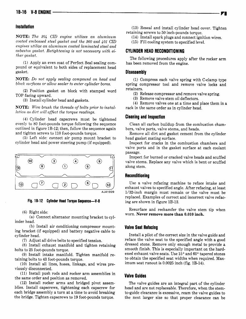
4 Cylinder head capscrews must be tightenedevenly to 80 foot-poundstorquefollowing the sequenceoutlinedin figure 1B-12; then, follow the sequenceagainand tighten screwsto 110 foot-poundstorque.
5 Left side: connect air pump mount bracket tocylinderheadandpowersteeringpumpif equipped.
®®c
___
®®
I
7
Q® G®D ®D @AJ41 929
Fig. 18-12 Cylinder Head Torque Sequence-V-8
6 Right side:a Connectalternatormountingbracketto cyl
inder head.b Install air conditioning compressormount
ing bracket if equippedand batterynegativecabletocylinder head.
7 Adjust all drive beltsto specifiedtension.8 Install exhaustmanifold and tighten retaining
bolts to 25 foot-poundstorque.9 Install intake manifold. Tighten manifold re
taining bolts to 43 foot-poundstorque.10 Install all lines, hoses,linkage,and wires pre
viously disconnected.11 Install pushrods and rocker arm assembliesin
the sameorder andposition as removed.12 Install rocker arms and bridged pivot assem
blies. Install capscrews,tightening each capscrewforeachbridgeassemblya turn at a time to avoidbreakingthe bridge. Tighten capscrewsto 19 foot-poundstorque.
13 Resealand install cylinder headcover. Tightenretainingscrewsto 50 inch-poundstorque.
14 Install sparkplugsandconnectignition wires.15 Fill cooling systemto specifiedlevel.
CYLINDER HEAD RECONDITIONINGThe following proceduresapply after the rocker arm
hasbeenremovedfrom the engine.
Disassembly1 Compresseachvalve spring with C-clamp type
spring compressortool and remove valve locks andretainers.
2 Releasecompressorandremovevalvespring.3 Removevalvestemoil deflectors.4 Removevalves oneat a time andplace them in a
rack in the sameorder as in cylinderhead.
Cleaning and InspectionCleanall carbonbuildup from the combustioncham
bers, valve ports, valve stems,andheads.Removeall dirt and gasketcementfrom the cylinder
headgasketmatingsurface.Inspectfor cracks in the combustionchambersand
valve ports and in the gasketsurfaceat each coolantpassage.
Inspectfor burnedor crackedvalve headsandscuffedvalve stems.Replaceany valve which is bentor scuffedalong stem.
ReconditioningUse a valve refacing machineto reface intake and
exhaustvalvesto specifiedangle.After refacing, at least1/32-inch margin must remain or the valve must bereplaced.Examplesof correctand incorrectvalve refacing areshown in figure 1B-13.
Resurfaceand rechamfer the valve stem tip whenworn. Never remove more than 0.010inch.
Valve Seat RefacingInstall a pilot of the correctsize in thevalveguide and
refacethe valve seatto the specifiedanglewith a gooddressedstone.Remove only enoughmetal to provide asmooth finish. This is especiallyimportanton the hardenedexhaustvalve seats.Use15° and60° taperedstonesto obtain the specifiedseatwidths whenrequired.Maximum seatrunout is 0.0025 inch fig. 1B-14.
Valve GuidesThe valve guidesare an integral part of the cylinder
headandarenot replaceable.Therefore,whenthe stem-to-guide clearanceis excessive,reamthe valve guidestothe next larger size so that proper clearancecan be

V-B ENGINE lB-li
1/32-INCHVALVE MARGIN
I
CORRECT VALVE FACING
Fig. 18-13 Valve Refacing
NO MARGIN
60117
obtained.Servicevalvesare availablein 0.003 inch, 0.015inch and0.030-inchoversize.
The following oversize valve guide reamersmay beused:
NOTE: Reamguides in steps. Start with the 0003-inchou’erszereamerand progress to the sizerequired.
Valve Guide Reamers
ReamerTool Number
,Size
J-6042-1J-6042-5J-6042-4
0.003-inch0.015-inch0.030-inch
Valve-Stem-to-Guide Clearance
Valve-stem-to-guideclearancemay be checkedby ei
therof two methods:Preferred Method
1 Mount dial indicatoradjacentto valve guide tobe checked.
2 Position valve slightly off its seat with valvestempushedlaterally away from dial indicator.
3 Setdial indicatorpushrod on stemof valveneartip and setgaugeto zero fig. 1B-15.
4 Read dial indicator while moving valve stemlaterally toward dial indicator. Stem-to-guideclearanceis indicatedon gauge.
Fig. 18-15 Valve Stem-to-Guide Clearance Measurement
Alternate Method
NOTE: Make certain the valvestemandguide bore arethoroughlycleanedbefhremeasuring.
1 Measurevalve stemdiameterwith a caliper micrometermidway betweenvalveheadandtip.
2 Selecta pilot from a valve refacingkit which fitssnugly in valve guide bore.
3 Determine valve stem-to-guide clearancebysubtractingdiameterof valvestemfrom sizeof thepilotselected.
Assembly
1 Thoroughly clean valve stemsand valve guidebores.
2 Install each valve in the samevalve guide fromwhich it wasremoved.
3 Install new valve stem oil deflector on each60268 valvestem
vs
INCORRECT VALVE FACING DIALINDICATOR
Fig. 18-14 Valve Seat Runout

18-18 V-B ENGINE
4 Positioneach valvespringandretaineron cylinderheadandcompressthevalvespringwith compressortool.
5 Install valvelocks andreleasetool.6 Tap each valve spring from side to side with a
light hammer to set the spring properly at cylinderhead.
HYDRAULIC VALVE TAPPETSThehydraulicvalve tappetconsistsof a body, plunger,
meteringdisc, plungercap, andlock ring fig. 1B-16.
LOCKRING
METERING DISC PLUNGER CAP
VALVE
VALVE
SPRING
VALVERETAINER
Fig. 1 8-16 Typical Hydraulic Tappet Assembly
The tappetoperatesin a guide borewhich hasan oilpassagedrilled into the adjoiningoil gallery.
When the tappet is on the heel of the cam lobe, oilunder pressureat the main oil gallery is admittedintothe tappet through a hole in grooved portion of thetappetbody.Oil flows into the plungerandthroughthecheck valve assemblymaintaining the tappet fullychargedfig. 1B-17.
During the normal valve opening events the tappetleaks off oil. Contact with the cam lobecausestappet
vu
42812
Fig. lB-il Hydraulic Tappet Operation Cycles
body movement, closing the check valve and transmitting zero-lashmovementof the pushrod to open theintakeor exhaustvalve.
In addition, oil under pressurein the plunger alsoflows through the meteringdisc, plungercap, andhollow pushrod to the rocker arm assembly.
1 Removecylinder headcover.2 Removerocker arms and bridgedpivot assem
blies, looseningeachcapscrewa turn at a time to avoidbreakingthe bridge.
3 Removepushrods.
NOTE: Keepro’cker arm assembliesand pushrods inthe sameorder as removed.
4 Removeintakemanifold.5 Removetappetfrom guideborein engineblock.
42811 Cleaning and InspectionReleaselock ring. Removeplungercap, meteringdisc,
plungerassembly,and plungerreturn spring from tappet body.
NOTE: Keep the tappetsand all componentsin thesameorder as removed.
Cleanall componentsof the hydraulic tappetassembly in a good cleaningsolvent to removeall varnish orgum deposits.
Visually inspect each tappetassemblyfor signs ofscuffing on the barrel and face of the tappet.Inspecttappet face for wear using a straightedgeacrossthetappetface. If the tappetface is concave,the corresponding lobeon the camshaftis worn andreplacementof thecamshaftandtappetsis necessary.
PLUNGER
CHARGING CYCLE LEAK DOWN CYCLEVALVE CLOSED VALVE OPEN
VALVESEAT Removal
OILINLETHOLE
it SPRING
TAPPET BODY

V-B ENGINE 1B-19
If any componentsof a tappetassemblyarenoticeablyworn or damaged,replacetheentire assembly.
Install plungerreturn spring, plunger, meteringdisc,and plunger cap in tappet body. Using a pushrod onplunger cap, compress plunger assembly arid installlockring.
Hydraulic Tappet Leak-Down TestAfter cleaningand inspection,leak-downtestthe tap
pet to ensureits zero-lashoperatingability. UseTool J5790 to testtappetleak-downaccuratelyfig, IB-18.
Fig. 1B-18 Hydraulic Tappet Leak-Down Tester J-5790
1 Swing weightedarm of testeraway from ram oftester.
2 Place 0.312 to 0.313 inch diameterbail bearingon plungercapof tappet.
3 Lift ram and place tappet with ball bearinginside testercup.
4 Lower ram, then adjust nose of ram until itcontactsball bearing.
5 Fill testercup with ValveTappetTest Iil J-5268until tappetis completelycovered.
6 Swingweightedarm onto ram and pumpup anddown on tappet to removeair. When air bubblescease,swingweightedarm away and allow plunger to rise tonormalposition.
7 Adjust nose of ram to align ijointer with SETmark on scaleof testerand tighten hex nut.
8 Slowly swing weighted arm onto ram. Rotatecup by turning handle at baseof tester clockwise onerevolution every two seconds.
9 Time leak-down from instant pointer alignswith START mark on scale until pointer aligns with0.125 inch mark.
A good tappetwill take20 to 110 secondsto leak-down.Discard tappetsoutsidethis range.
NOTE: Do not charge the tappet assemblieswith engine oil as they will charge themselveswithin three toeight mm.u tes ofengineoperation.
Installation1 Dip each tappet assembly in Jeep Engine Oil
SupplementEOS, or equivalent, and install tappet insameborefrom which it wasremoved.
2 install pushrodsin thesameorder as removed.3 install rockerarm and bridgedpivot assemblies.
Install capscrews,tightening each capscrew for eachbridge assemblya turn at a time to avoid breakingthebridge. Tighten capscrewsto 19 foot-poundstorque.
4 Pour remaining EOS over entire valve trainmechanism.
NOTE: Do not drain the EOSfrom the enginefor atleast1,000miles or until the nextscheduledoil change.
5 install cylinder headcover and gasket. Tightenretaining screwsto 50 inch-poundstorque.
6 I[nstall intakemanifold andnew gasketand endseals.Tighten manifold retainingbolts to 43 foot-poundstorque.
7 Install all lines, hoses, linkage,and wires previously disconnectedfrom intakemanifold.
VIBRATION DAMPERThe vibration damperis balancedindependentlyand
then rebalancedas part of the complete crankshaftassembiLy.
Do not attempt to duplicate original damper balanceholeswhen installing a servicereplacement. Thevibration damperis not repairableand is servicedonlyas a completeassembly.
Removal1 Loosen damper attaching screw with all belts
attached.2 Loosenalternatordrive belt.3 Loosenair conditioningdrive belt if equipped
andmove aside.4 Loosen power steeringdrive belt if equipped
andmove aside.5 Removedamperdrive pulley retainingbolts and
damperpulley from vibration damper.6 Removedamperretainingbolt.7 Use Vibration DamperRemovalTool J-21791to
removedamperfrom crankshaftas shownin figure 1B-19.
Installation1 Apply a light film of engineoil to sealcontacting
surfaceof vibration damper.
vu
POINTER
PUSHROD
/RAM
WEIGHTEDARM
HANDLE
r.
41891

18-20 V-B ENGINE
Fig. 18-19 Vibration Damper Removal
2 Align key slot of vibration damper withcrankshaft.
3 Install damperretainingbolt andtighten to 55foot-poundstorque.
4 Install damperpulley and retaining bolts andlockwashers. Tighten bolts to 30 foot-poundstorque.
5 Install drive belts and tighten to specifiedtension.
TIMING CASE COVERThe timing case cover is die-cast aluminum with a
crankshaftoil sealto preventoil leakageat thevibrationdamperhub fig. 1B-20. The oil seal is installed fromthe backside of the timing casecover.It is necessarytoremove the cover whenever oil seal replacementisrequired.
A graduatedscalecastinto the cover is usedfor ignition timing. A hole is provided for checking ignitiontiming with a magnetictiming probe. Refer to Section4A for ignition timing procedureand magnetictimingprobedescription.
The engine oil pump, oil passagesand coolant passagesare incorporatedwithin the timing casecovercasting. The timing casecover castingis also usedto mountthe fuel pump, distributor, and waterpump.
Removal1 Draincooling systemandcylinderblock.2 Disconnectradiatorhosesandbypasshose.
TIMING CHAINCOVER GASKET
Fig. 18-20 Timing Case Cover Assembly
41933
3 Removeall drive belts.4 Removefan andspacerassembly.5 If equippedwith air c9nditioning, removecom
pressorand bracket assemblyfrom engine and moveaside.Do not disconnect the air conditioning hoses.
6 Remove alternator, alternator mountingbracketandback idler pulley from engine.
7 Disconnectheaterhoseat water pump.8 Removepowersteeringpump if equippedand
air pump andmountingbracketas an assembly.Do notdisconnectpower steeringhoses.
9 Remove distributor cap and mark rotor andhousingposition.
10 Removedistributor.11 Removefuel pump.12 Removevibration damperpulley andretaining
bolts andlockwashers.13 Removevibration damperusingtool J-21791.14 Removetwo front oil panbolts.15 Removebolts which securetiming casecover to
engineblock.
NOTE: The cover retaining bolts vary in length andmustbe instailed in the samelocation as removed.
16 Remove cover by pulling forward until free ofthe locating dowel pins.
17 Cleangasketsurfaceof cover.18 Removeoil seal.
NOTE: The oil seal always should be replacedwhenever the timing casecover is removed.Refer to Oil SealReplacementin thissection.
Installation1 Remove lower locating dowel pin from engine
block.
OIL SLINGER
vu
CHAIF COVER
ENGINE ACCESSORYDRIVE PULLEY
TIMING CASECOVER OIL SEAL
VIBRATION DAMPER

V-8 ENGINE 18-21
NOTE: The dowel pin is required fbr correct coveralignmentand either must be reusedor a replacementdowelinstailed after the coveris in position.
2 Use a sharpknife or razorbladeto cut both sidesof oil pangasketflush witFi engineblock.
3 Using original gasketas guide, trim replacement gasketto correspondto amountcut off at oil panfig. 1B-21.
4 Apply sealer to both sides of new gasket andinstall gasketon timing casecover.
5 Installnew front oil panseal.6 Align tonguesof new oil pangasketpieceswith
oil pansealandcementinto place on cover fig. 1B-21.7 Apply a bead of JeepGasket-in-a-TubeRTV
silicone,or equivalent,to cutoff edgesof original oil pangaskets.
8 Placetiming casecover into positionand installfront oil pan bolts.
9 Tighten bolts slowly and evenly until coveralignswith upperlocating dowel.
10 Install lower dowel through coverand drive intocorrespondinghole in engineblock.
11 Install cover retainingbolts in the same]ocationas removed.Tighten to 25 foot-poundstorque.
12 Install vibration damper.Tighten retainingboltto 90 foot-poundstorque.
13 Install damperpulley andretainingbolts.14 Install fuel pump.15 Install distributor with the rotor and housingin
the sameposition as it was prior to removal.16 Install distributorcapandconnectheaterhose.17 Install power steeringpump and air pump and
mountbracket if equipped.18 Install alternatorandalternatormount bracket.19 Install air conditioningcompressorand bracket
assemblyif equipped.
20 ]:nstaufan andspacerassembly.21 1:nstall all drive beltsandtightento thespecified
tension.22 Connectradiatorhosesandbypasshose.23 Fill coolingsystemto specifiedlevel.24 Startengineandcheckfor oil or coolantleaks.25 Adjust initial ignition timing to specified
setting.
Oil Seal ReplacementTiming casecovermust beremovedto replaceseal.1 Pry out original seal from inside timing case
coverandcleanseal bore.2 Apply a light coat of Perfect Sealcompound,or
equivalent,to outersurfaceof a new seal.3 Drive seal into place from inside the cover with
Seal Installer Tool J-22533 until it contactsthe outerflangeof the coverfig. 1B-22.
4 Apply a light film of engineoil to lips of neopreneseal.
FIg. 1 B-22 Timing Case Cover Oil Seal Replacement
TIMING CHAINThe timing chain is of the singlerow type andhas 62
links and pins. To ensurecorrect valve timing, installthe timing chain with the timing marks of the crankshaft andcamshaftsprocketsproperlyaligned.A worntiming chain will adverselyaffect valve timing. If thetiming chain deflects more than 1/2 inch, it should bereplaced.
P’i
OIL PAN.- FRONT SEAL
Fig. 1B-21 Oil Pan Front Seal Installation
TOOLJ-22533
N
41935

18-22 V-8 ENGINE
Chocking Valve Timing1 Removesparkplugs.2 Removecylinder headcoversandgaskets.3 Remove rocker arms and bridgedpivot assem
blies from No. 1 cylinder.4 Rotate crankshaftuntil No. 6 piston is at Top
Dead Center TDC on compressionstrokethis placesNo. 1 piston at TDC on the exhauststroke in valveoverlapposition.
5 Rotate crankshaftcounterclockwise90 degreesas viewedfrom front.
6 Install dial indicator on No. 1 intakevalvepushrod end.
7 Setdial indicator to zero.8 Crank engine slowly in direction of rotation
clockwise viewed from front until dial indicator indicates0.020inch for 304 and360 CID enginesand0.025inch for 401 CID engines.
9 At this point, milled timing mark on vibrationdampershould be in line with TDC markingon timingcasecover.
If more than 1/2-inch variation in either directionexists, remove timing chain cover and inspect timingchain installation.
Check for incorrect camshaftsprocket indexing. Thesprocketkeyway shouldalign with the centerlineof thefirst lobe on the camshaft.
Removal1 Removetiming casecover.2 Removecrankshaftoil slinger.3 Removecamshaftsprocket retaining bolt and
washer.4 Removedistributor drive gear and fuel pump
eccentric.5 Rotatecrankshaftuntil the zerotiming markon
the crankshaftsprocketis closestto and in a centerlinewith the zerotiming markon thecamshaftsprocketfig.1B-23.
NOTE: Instail crankshaft screw and several thickwashersto fttciiitate turning crankshaft.
6 Removecrankshaftsprocket,camshaftsprocketandtiming chainas an assembly.
Installation1 Assemble timing chain, crankshaft sprocket,
and camshaftsprocketwith timing marksaligned fig.1B-24.
2 Install assemblyto crankshaftandcamshaft.3 Install fuel pump eccentricanddistributordrive
gearfig. 1B-24.4 Install camshaft, washer and retaining bolt.
Washer fits into recess in distrubutor drive gear.Tightenbolt to 30 foot-poundstorque.
Fig. 1B-23 Sprocket Alignment
1
NOTE: Thefuel pumpeccentricmust be installedwiththe stampedword REARfacing the camshaftsprocket.
70451
41936
KEY
GEAR
DISTRI BUTORDRIVE GEAR
CAMSHAFT
FUELPUMPECCENTRIC
SCREW
Fig. 1B-24 Camshaft Drive Gear

V-8 ENGINE 1B-23
5 To ensurecorrectinstallationof timing chain:a Rotate crankshaft until timing mark on
camshaftsprocket is on a horizontal line at 3 o’clockposition.
b Beginningwith pin lirectly adjacentto camshaftsprockettiming mark, count numberof pins downward to timing mark on crankshaftsprocket.
c There should be 20 pins betweenthesetwopoints.The crankshaft sprocket timing mark must bebetweenpins 20 and 21 fig. 1B-25.
6 Install crankshaftoil slinger.7 Remove timing case cover oil seal, install re
placementoil seal.8 Install timing casecover usingreplacementgas
ket. Tighten retainingbolts to 2 foot-poundstorque.
CAMSHAFT AND BEARINGSThe camshaftis supportedby five steel-shelled,bab
bit-lined bearings which have been pressedinto theblock and line reamed,The camshaft journals are stepbored, beinglargerat the front bearingthan at the rear,to permit easyremovalandinstallationof thecamshaft.All camshaftbearingsare lubricatedunderpressure.
NOTE: Do not replace camshaft bearings unless required specjal tools ,for removing and installing areavailable.
Camshaftend play is maintainedby the load placedon the camshaftby the oil pump and distributor drivegear. The helical cut of the gear holds the camshaftsprocketthrust face against the cylinder block face tomaintain zero end play duringengineoperation.
Camshaft IdentificationThe 401 CID engine camshaft is identified by white
marks betweenthe No. 3 and4 camshaftbearings.The 304 and360 CID enginecamshafts,which are the
same,haveno identifying paint marks.
Cam Lobe Lift MeasurementCamlift may be checkedwith a dial indicator.1 Removerockerarm cover andgasket.2 Remove rocker arms and bridged pivot assem
blies. Alternately loosen capscrewsa turn at a time toavoid b:reakingthe bridge.
3 Removesparkplugs.4 Install a dial indicator on end of pushrod fig.
1B-26.
NOTE: A piece qf rubber tubing may beusedto securedial indicator plunger to push rod.
5 Rotate crankshaft until cam lobe base circlepush rod down is undervalve tappet.
6 Setdial indicatorto zero.
P1
AJ41 937
Fig. 1B-25 Correct Timing Chain Installation
Fig. IB-26 Cam Lobe Lift Measurement
1B-24 V-8 ENGINE
7 Rotatecrankshaftuntil point of maximum pushrod upwardmovementoccurs.
8 Read travel at dial indicator. Correct lift is0.260 to 0.270 inch for 304 and 360 CID engines and0.0280to 0.0290 inch for 401 CID engine.
Removal1 Draincooling systemandcylinderblock.2 Removeradiatorassembly.3 If equippedwith air conditioning, remove con
denserand receiverassemblyas chargedunit. Refer toSection13A-Air Conditioningfor detailedprocedure.
4 Removecylinderheadcoversandgaskets.5 Remove rocker arms and bridged pivot assem
blies, looseningeach capscrewa turn at a time to avoidbreakingthe bridge.
6 Removepushrods.
NOTE: Keep push rods, rocker arm assemblies,andtappetsin the sameorder as removed.
7 Removeintakemanifoldassembly.8 Removedrive belts.9 Removefan andhubassembly.
10 Removedistributor.11 Removedamperpulley.12 Removevibration damper.13 Removetiming casecover.Removeoil seal.14 Install crankshaftscrewandseveralthick wash
ersto facilitatecrankshaftrotation.15 Rotatecrankshaftuntil timing mark on crank
shaft sprocket is closest to and in a centerline withtiming mark on camshaftsprocket.
16 Remove retaining bolt from camshaft andcrankshaft.
17 Remove distributor drive gear and fuel pumpeccentricfrom the camshaft1B-24.
18 Removecrankshaftsprocket,camshaftsprocketandtiming chainas an assembly.
19 Remove hood latch support bracket upper retaining screws and move bracket,as required,to allowremovalof camshaft.
20 Removefront bumperor grille, as required,andremovecamshaft.
InspectionInspectthe camshaftbearingjournals for an uneven
wear patternor rough finish. Either condition will necessitatecamshaftreplacement.
Inspectthe distributordrivegearfor damageor excessive wear.
Inspectfuel pumpeccentricfor excessivewear.Inspect each cam lobe and the matching hydraulic
valve tappet for wear. If the face of the tappetis wornconcaveand the matchingcamshaftlobe is worn, boththe camshaftandtappetsmustbe replaced.
V.
Installation1 Lubricate entire camshaftgenerouslywith Jeep
EngineOil SupplementEOS, or equivalent.2 Carefully install camshaftinto engineblock.3 Assemble timing chain, crankshaft sprocket,
andcamshaftsprocketwith the timing marksalignedasat time of removal.
4 Install chain andsprocketsassemblyto engine.Recheckinstallation as shown in figure 1B-23.
5 Install fuel pumpeccentricanddistributordrivegear to camshaft.
6 Install replacementtiming case cover gasket.Refer to Timing CaseCover in this section.
7 Install replacementsealin timing casecover.8 Install timing casecover.9 Install vibration damper.Apply oil to damper
screw washer and tighten screw to 90 foot-poundstorque.
10 Install damper pulley and retaining bolts.Tighten bolts to 30 foot-poundstorque.
11 Install hydraulic valve tappetslubricatedwithJeep Engine Oil Supplement, or equivalent, duringinstallation.
NOTE: Do not drain the EOSfrom the enginefor atleast1,000 miles or until the nextscheduledoil change.
12 Install intakemanifold assembly.13 Install pushrods.14 Install rocker arms and bridged pivot assem
blies. Install capscrews,tightening each capscrewforeachbridge assemblya turn at a time to avoidbreakingthe bridge. Tighten capscrewsto 19 foot-poundstorque.
15 Install cylinderheadcoversandgaskets.16 Install fuel pump.17 Rotatecrankshaftuntil No. 1 piston is at TDC
position on compressionstroke.
NOTE: After No. 1 intakevalve has closed, TDC can bereachedby rotating the crankshaftclockwiseas viewedfrom the front until the timing mark or the damperaligns with TDC on the timing casecover.
18 Install distributor so that rotor is aligned withNo. 1 terminal of the capwhenfully seatedon block.
19 Install distributorcap.20 Install ignition wires.21 If removed, install air conditioning condenser
and receiverassembly.Refer to Section13A-Air Conditioning for procedureto purgecompressorair.
CAUTION: Both servicevalvesmust be open beforethe air conditioningsystemis operated.
22 Install hood latch support bracket retainingscrewsandtightensecurely.
23 If removed,install front bumperor grille.24 Install radiator.25 Fill coolingsystemto specifiedlevel.

V-B ENGINE 1B-25
OIL PAN
Removal1 Drainengineoil.2 Removestarter.3 Removeoil pan.4 Remove oil pan front and rear neopreneoil
seals.Thoroughly clean gasketsurfacesof oil pan andengine block. Removeall sludge and dirt from oil pansump.
Installation1 Install oil panfront sealto timing casecover and
apply generousamountof JeepGasket-in-a-TubeRTVsilicone, or equivalent,to end tabs.
2 Cement replacementoil pan side gaskets intoposition on engineblock and apply generousamount ofJeepGasket-in-a-TubeRTV silicone, or equivalent,toside gasketcontactingsurfaceof sealend tabs.
3 Install seal in recessof rear main bearingcapmaking certainit is fully seated.
4 Apply engineoil to oil pan contactingsurfaceoffront andrearoil panseals.
5 Install oil panandtighten drain plugsecurely.
NOTE: Tighten1/4-20 oil pan .sereo’s to 7.foot-poundstorque and 5/16-18 oil pan screws to 4 foot-poundstorque.
6 Install starter.7 Fill crankcaseto specified level with cleanoil.
OIL FILTERA full flow oil filter mountedon the lower right-hand
side of the engineis accessiblefrom below the chassis.A bypassvalve, incorporated in the filter mounting
base, provides a safety factor in the event the filterbecomesinoperativeas a result of dirt or sluge accumulation. Oil Filter Remover Tool J-22700 will facilitateremoval.
Before installation,apply a thin film of oil to thefiltergasket. Do not use grease. Install filter until gasketcontactsthe seatof the adapter.Tighten by handonly,following instructionson replacementfilter. Operateengine at fast idle and checkfor leaks.
OIL PUMPThe positive-displacementgear type oil pump is
driven by the distributor shaft, which in turn is drivenby a gear on the camshaftfig. 1B-4. The pump,whichis part of the timing casecover, incorporatesa pressurerelief valve to regulatemaximum pressure.
Crankcaseoil enters the pump after being drawnthrough the pickup tube and screenassembly,the horizontal main oil gallery, and the connectingpassageinthe timing casecover.
Oil pump removalor replacementwill not affectdistributor timing as the distributordrive gearremainsinmeshwith the camshaftgear.
Oil Pressure Relief ValveThe oil pressurerelief valve is not adjustable.A set
ting of 75 pounds maximum pressureis built into thetensionof the spring.
In the relieved position, the valve permits oil to bypass through a passagein the pump cover to the inletside of the pump.
Removal1 Removeretainingscrewsand separateoil pump
cover, gasketand oil filter as an assemblyfrom pumpbody timing casecover.
2 Removedrive gear,drive gear shaftand drivenidler gearby sliding them out of body.
3 Remove oil pressurerelief valve from pumpcoverfor cleaningby removingretainingcapandspring.
Clean cover thoroughly. Check operation of reliefvalve by insertingreleasevalve andcheckingto seethatit slidesbackandforth freely. If not, replacepumpcoverand releasevalve.
Gear End Clearance MeasurementThis proceduredeterminesthe distancebetweenthe
end of the pump gear and the pump coVer. Excessivepump clearanceis indicated by good oil pressurewhencold; low or no pressureafter a hot engine start-up.
Preferred Method
1 Place strip ofeachgearfig. 1B-27.
Plastigageacrossfull width of
VI
PLASTI GAGE
70298
Fig. 18-27 Oil Pump Gear End ClearanceMeasurement-.--Plastigage Method

1B-26 V-8 ENGINE
2 Install pump cover and gasket.Tighten screws
to 55 inch-pounds.3 Remove pump cover and determineamount of
clearanceby measuringwidth of compressedPlastigagewith scaleon Plastigageenvelope.Correctclearancebythis methodis 0.002 to 0.006 inch 0.002preferred.
Alternate Method1 Placestraightedgeacrossgearsandpumpbody.2 Select a feeler gaugewhich will fit snugly but
freely betweenstraightedgeandpumpbody fig. 1B-28.
NOTE: Make certain gears are up as far as possbileinto body. Correct clearanceis 0.004 to 0.008 inch 0.008clearancedesired.
If clearanceis excessive,measuregearlength. If gearlength is incorrect, replacegears.If gear length is correct, install a thinner gasket.
NOTE: Make a thinner gasketfrom locally procuredmaterial.
Gear-to-Body Clearance1 Insert feeler gauge between gear tooth and
pumpbody inner wall directly oppositethe point of gearmesh. Select feeler gaugewhich fits snugly but freelyfig. 1B-29.
1 Rotategearsto checkeachtooth in this manner.Correct clearance is 0.0005 to 0.0025 inch 0.0005desired.
2 If gear-to-bodyclearanceis morethanspecified,measuregeardiameter.If diameteris incorrect, replacegears.If diameteris correct, checkgear endclearanceand correct. If gear endclearanceis acceptable,replacetiming casecover.
Installation1 If removed, install oil pressurerelief valve in
pumpcover with spring andretainingcap.2 Install idler shaft, idler gear and drive gear
assembly.
NOTE: To ensureself-primingof the oil pump,fill thepump with petroleumjelly prior to the installation ofthe oil pumpcover. Do not usegreaseof any type.
3 Install pump cover and oil filter assemblywithreplacementgasket.Tightenretainingscrewsto 55 inch-poundstorque.
REAR MAIN BEARING OIL SEALTherearmain bearingoil sealconsistsof a two-piece,
neoprene,single-lip seal to seal the rear of the crankshaft. Correct installation of the seal will ensureleak-free engineoperationfig. 1B-30.
Removal1 Drainengineoil.2 Removestartermotor.3 Removeoil pan.4 Remove oil pan front and rear neoprene oil
seals.5 Removeoil panside gaskets.6 Thoroughlycleangasketsurfacesof oil panand
engineblock.Removeall sludgeanddirt from oil pan.7 Removerearmain bearingcap.8 Removeanddiscardlower seal.
VI
FEELERGAUGE
FEELERGAUGE
J
7,STRAIGHTEDGE
Fig. 1 B-29 Gear-to-Body Clearance Measurement
41940
Fig. 18-28 Gear Height Measurement
41 939

V-8 ENGINE 1B-27VI
LIP
RTV SILICONETOP ANDBOTTOM BOTHSIDES
RTV SILICONEON CHAMFEREDEDGES
Fig. 1B-30 Rear Main Oil Seal Installation
OUTSIDEOF SEAL
EDGES
41904
NOTE: To ensure leak-freeoperation, the upper andlowerseal halvesmustbe replacedin pairs.
9 Clean main bearingcap thoroughly to removeall sealer.
10 Loosenall remainingmain bearingcapscrews.11 With a brassdrift and hammer,tap the upper
seal until sufficient sealis protrudingto permit pullingsealout completely.
Installation1 Wipe seal surfaceof the crankshaftclean and
then oil lightly.2 Coat block contactingsurfaceof the new upper
sealwith soap,andlip of sealwith engineoil fig.. 1B-28.3 Install uppersealinto engineblock.
NOTE: The lip of the seal mustji.ce to the front of theengine.
4 Coat both sides of replacementlower seal endtabs with Jeep Gasket-in-a-TubeRTV silicone, orequivalent, being careful not to apply sealer to lip ofseal.
5 Coat outer curved surface of lower seal withsoapandlip of sealwith engineoil.
6 Install sealinto caprecessandseatfirmly.7 Place JeepGasket-in-a-TubeRTV silicone, or
equivalent,on both chamferededgesof rear main bearing cap.
CAUTION: Do not apply sealerto cylinder blockmating surfaceof rear main cap as bearing clearancecouldbe increased.
8 Install rearmain bearinginserts.9 Install rearmainbearingcap.
10 Tighten all main bearingcapscrewsto 100 foot-poundstorque.
11 Install oil pan using new gasketsand seals.Tighten drain plug securely.
12 Install startermotor.13 Fill crankcaseto specifiedlevel with cleanoil.
CYLINDER BLOCK
Disassembly1 Removeengine assemblyas outlined earlier in
this section.2 Useenginestandto supportengineassembly.3 Removedistributor.4 Removecylinderheadcovers.5 Remove rocker arms and bridged pivot assem
blies. At each bridge, loosen capscrewsalternately aturn at a time to avoid breakingbridge.
6 Removepushrods.7 Removeintakemanifoldassembly.8 Removevalvetappets.9 Removecylinderheadsandgaskets.
10 Positionpistons,one at a time, near bottom oftheir stroke and use ridge reamerto remove any ridgefrom top endof cylinderwalls.
11 Loosen all drive belts. Removepower steeringpump, air pump and AC compressor bracket, ifequipped.
12 Removedamperpulley andvibration damper.13 Removetiming casecover.14 Removeoil pan.15 Removecamshaft.16 Removeconnectingrod bearingcapsandinserts
andkeep in sameorder as removed.
NOTE: Connectingrodsand capsare stampedwith thenumberof the cylinder to which theywere assembled.
17 Remove connectingrod and piston assembliesthrough top of cylinder bores. Be careful that connecting rod bolts do not scratch connecting rod journals or cylinder walls.
NOTE: Piecesof rubber hose can be pushedover therod bolts to preven.tdamageto the rod journals.
18 Removeoil pickup tube andscreenassembly.19 Removemain bearingcapsandinserts.20 Removecrnkshaft.
Cylinder Bore ReconditioningInspectthe cylinder boresfor scoring,taper,andout-
of-round. Check with an insidemicrometeror telescopegaugefrom the top to the bottom of the cylinders fortaper.Checkfor an out-of-roundconditionby measuringacrossthe cylinder boresat two points: parallel to thecrankshaftandperpendicularto the crankshaft.
If cylinder taperdoesnotexceed0.005 inch andout-ofrounddoesnot exceed0.003 inch, the cylinderboremaybecorrectedby honing.

1B-28 V-B ENGINE
If the cylinder taperor out-of-roundconditionexceedstheselimits, the cylindermust be boredand then honedfor an oversizepiston.
Move the hone up and down at a sufficient speedtoproduce a uniform crosshatchpatternon the cylinderwalls.
Removal of glaze from the cylinder wall for quickerring seatingcan he accomplishedby various methods.When an expandingtype hone is used,do not use morethan ten strokesto reconditiona cylinderwall. A strokeis onedown-and-upmotion.
Successfulring installationdependsupon cleanlinessduring the honing operation and careful handling ofparts.The enginehearingsand lubricationsystemmusthe protectedfrom abrasives.
Rigid type honesarenot bebeusedto removecylinderglaze as there is always a slight amount of taper incylinderwalls after the enginehasbeenin service.
Prior to fitting pistons,the cylinder boresshould bescrubbedclean with a hot water anddetergentsolution.After cleaning, apply light engineoil to cylinder wallsandthen wipe with a clean, lint-free cloth.
NOTE: If crankshaft remains in block, cover the connecting rodjournals with clean, clothsduring honingandcleaningoperation.
Assembly1 Install and lubricate’ uppermainbearinginserts
andrearmain upperseal. Lubricateseallip.2 Install crankshaft.3 Install main bearingcapsandinserts.If replace
ment bearingsand/or crankshaftare used,Plastigageeachbearing.
4 Install newoil pickup tubeandscreenassembly.Be sureplastic buttonis insertedin screen.
5 Install camshaft.6 Prior to installing the connectingrod andpiston
assembliesinto cylinder block, arrangepistonring gapsso that:
a Oil spacer gap is on centerline ±20° ofeitherskirt face.
h Oil rail gapsare 180° apartand inline withpiston pin centerline±20°.
c Number 2 compression ring gap is180°±20° from top oil rail gap.
d Number 1 compression ring gap is180°±20° from the number2 compressionring gap.
7 Lubricate piston and ring surfaceswith cleanengineoil.
NOTE: Be sure piston notch faces forward and oilsquirt hole facescamshaftfig. 1B-31.
8 Use a piston ring compressortool to install connecting rod and piston assembliesthrough top of cylin
NOTE: Be careful that connectingrod bolts do notscratch connectingrod journals or cylinderwalls. Placelength of rubber hoseover the connectingrod bolts forprotectionduring installation.
9 Install connectingrod bearingcapsand insertsin sameorder as removed.Tighten nuts on 304 and360CID enginesto 28 foot-poundstorque. Tighten nuts on401 CID enginesto 39 foot-poundstorque.
10 Install camshaftandtiming chain.11 Install timing case cover and gaskets.Refer to
Timing CaseCoverearlier in this section.12 Install engineoil pan usingreplacementgaskets
and seals.Tighten drain plugsecurely.13 Install vibration damperanddamperpulley.14 Install cylinderheadandgaskets.15 Install valvetappets.16 Install intakemanifold andnew gaskets.17 Install pushrods.18 Install rocker arms and bridged pivot assem
VI
CYLINDERNUMBEROUTBOARD
Fig. 1B-31 Connecting Rod and Piston Assembly
der bores. hues. Install capscrews,tightening each capscrewfor

VI V-B ENGINE 1B-29
eachbridgeassemblya turn at a time to avoid breakingthe bridge. Tighten capscrewsto 19 foot-poundstorque.
19 Turn crankshaftto bring No. 1 pistonto TDC ofcompresionstrokefor later installationof distributor.
20 Resealandinstall cylindercovers,21 Install power steeringpump, air pump and AC
compressor,if removed.22 Install distributor.
a Pointrotor to No. 1 sparkplugwire position.b Turn oil pump shaft with long screwdriver
to allow distributorshaft to engageoil pump.c With rotor pointingto No. 1 sparkplugwire
position, rotate housingcounterclockwiseuntil leadingedgeof trigger wheel segmentis aligned with centerofsensor.
d When engineis installedandrunning, checkignition timing asoutlinedin Chapter4A.
23 Removeenginefrom stand.24 Install engine assembly as outlined earlier in
this section.
CONNECTING ROD AND PISTON ASSEMBLIESUse theseproceduresto service connectingrods and
pistonswith the enginein the vehicle.
Removal1 Removecylinderheadcovers.2 Remove rocker arms and bridged pivot assem
blies, looseningeachcapscrewa turn at a time to avoidbreakingthe bridge.
3 Removepushrods.4 Removeintakemanifold assembly.
NOTE: It is not necessaryto removema.’nfoid fromexha;ust pipe.
5 Removecylinderheadandgasket.6 Position pistons, one at a time, nearbottom of
their strokeand usea ridge reamerto removeany ridgefrom top end of cylinder walls.
7 Drain engineoil.8 Removeoil pan.9 Remove connectingrod bearing caps and in
serts.Keep in sameorder as removed.
NOTE: C’onnectingrods and caps are stampedwith thenumberof the cylinder to which they‘were assembled.
10 Remove connectingrod and piston assembliesthrough the top of cylinderbores.Be careful that connecting rod bolts do not scratch connecting rod journals or cylinder walls.
NOTE: A piece of rubber hose can bepushedon overthe rod bolts to avoiddamageto the rod journals.
Installation
a light film of cleanengineoil to boreswith a clean,lint-free cloth.
2 Prior to installing connectingrod and pistonassembliesinto engine,arrangepistonring gapsso that:
a Oil spacer gap is on centerline ±20° ofeitherskirt face.
b Oil rail gapsare 180° apartand in line withpiston pin centerline±20°.
c Number 2 compression ring gap is180°±20° from top oil rail gap.
d Number 1 compression ring gap is180°±20° from the number2 compressionring gap.
3 Lubricate piston and ring surfaceswith cleanengineoil.,
NOTE: Be sure piston notch faces forward and oilsquirt hole fixces camshaftfig. 1B-31.
4 Use piston ring compressortool to install connectingrod and piston assembliesthrough top of cylinder bores.Be careful that connectingrod bolts do notscratch connecting rod journals or cylinder walls.
NOTE: Place lengths of rubber hose over the connecting rod bolt’s ,for protectionduring installation.
5 Install connectingrod bearingcapsand insertsin sameorder as removed.Tighten retainingnuts to 33foot-poundstorqueon 304 and360 CID engines.Tightenretaining nut on 401 CID engines to 39 foot-poundstorque.
6 Install engineoil pan usingreplacementgasketsandseals.Tighten drain plugsecurely.
7 Install cylinderheadsandgaskets.8 Install pushrods.9 Install rocker arms and bridged pivot assem
blies. Install capscrews,tightening each capscrewforeachbridgeassemblya turn at a time to avoid breakingthe bridge. Tighten capscrewsto 19 foot-poundstorque.
10 Install intakemanifold assembly.11 Resealandinstall cylinderheadcovers.12 Fill crankcasewith newoil to specifiedlevel.
CONNECTING RODThe connectingrods for 304 and 360 CID enginesare
malleable-iron and 401 CID engines are forged steel.Both types are independentlybalanced.The crankshaftend of the connectingrods incorporatesa two-piecebearinginsert. A squirt hole at the crankshaftendprovides lubrication for the cylinder walls, pistons, andpiston pins. It must face inward when the connectingrod is installedfig. 1B-31. The removablebearingcaphas a numberfrom 1 through 8 stampedon it and theadjacentmachined surface of the rod to identify thecylinder in which the rod wasassembled.The pistonendof the rod is a 2000-poundpress-fitto the piston pin.
Have the connectingrod alignmentcheckedby acompetentmachineshopwheneverenginewear patternsordamageindicates probable rod misalignment.Alwaysreplacebentconnectingrods.1 After thoroughlycleaningcylinder bores,apply

1B-30 V-8 ENGINE
Connecting Rod BearingsThe connectingrod bearingsfor all V-8 enginesare
steel-backed,aluminum-alloy,precisiontype.The connectingrod bearingsare select fit to their
respectivejournalsto obtain the desiredoperatingciearance. In production, the selectfit is obtainedby usingvarioussized colorcodedbearinginsertsas shownin thebearingfitting chart.The bearingcolor codeappearsonthe edgeof the insert. Bearingsize is not stampedoninserts usedin production.
The rod journal size is identified in production by acolor codedpaint markon the adjacentcheekor counterweight toward the flangedrear endof the crankshaft.Use color codesshown in the bearingfitting chart toidentify journal size and select the correctbearinginserts to obtain properclearances.
Whenrequired,different sizedupperandlower bearing insertsmay be usedas a pair. A standardsize insertis sometimesusedin combinationwith a 0.001-inchundersize insert to reduceclearanceby 0.0005 inch 1/2thousandthof an inch.
CAUTION: Never use bearing inserts with greaterthan0.001-inchthfferencein size in pairs.
Example:
Bearing Insert Pairs
Insert Correct Incorrect
Upper Standard Standard
Lower 0.001-inchundersize
0.002-inchundersize
70242
Servicereplacementbearing inserts are available inpairs in the following sizes: standard,0.001-inchundersize, 0.002-inch undersize, 0.010-inch undersize, and0.012-inch undersize.The size is stampedon the backofthe servicereplacementinserts.
NOTE: The 0.002- and 0.012-inchundersizeinserts arenot usedin production.
RemovalUse this procedureto serviceconnectingrod bearing
with the enginein the vehicle.1 Drainengineoil.2 Removeoil pan.3 Rotate crankshaftas required to position con
necting rod journal at bottomof stroke.4 Removebearingcapsandlower inserts.5 Remove upper insert by rotating insert out of
connectingrod.
NOTE: Do not mix bearing caps.Eachconnectingrodand matchingcap is stampedwith the cylindernumberon a machinedsurfacewhichfacesthe camshaftside ofthe engine block. The numbers are located on a macliined s’uxfaceoppositethe squirt holes fig. 1B-32.
ROD ANDCYLINDERNUMBERSTO OUTSIDE
Fig. 1 B-32 Rod Number and Squirt Hole LocatIon
Connecting Rod Bearing Fitting Chart
Crankshaft Connecting Rod JournalColor Code and Diameter in Inches
Journal SizaJ
Bearing Color Code
Upper Insert Size Lower Insert Size
304 . 360 CID EnginesYellow - 2.0955 to 2.0948 StandardOrange - 2.0948 to 2.0941 0.0007 UndersizeBlack - 2.0941 to 2.0934 0.0014 UndersizeRed - 2.0855 to 2.0848 0.010 Undersize
Yellow - StandardYellow - StandardBlack - .001-inch UndersizeRed - .010-inch Undersize
Yellow - StandardBlack - .001-inch UndersizeBlack - .001-inch UndersizeRed - .010-inch Undersize
401 CID Engine-Yellow - 2.2485 to 2.2478 Standard
Orange - 2.2478 to 2.2471 0.0007 UndersizeBlack - 2.2471 to 2.2464 0.0014 UndersizeRed - 2.2385 to 2.23780.010 Undersize
Yellow - StandardYellow - StandardBlack - .001-inch UndersizeRed - .010-inch Undersize
Yellow - StandardBlack - .001-inch UndersizeBlack - .001-inch UndersizeRed - .010-inch Undersize
VI
SQUIRTHOLETOINSIDE
AJ41 944
60270

V-B ENGINE 1B-3l
Inspection
LOCKING
/TABS
UPPER
Fig. 18-33 Connecting Rod Bearing Inspection
60757
1 Cleaninserts.2 Inspectlinings andbacksof inserts for irregular
wear pattern. Note any scraping,stresscracks or distortion fig. 1B-33. If bearinghas spunin rod, replacebearingandconnectingrod andinspectcrankshaftjournal for scoring.
3 Inspectfor material imbeddedin linings whichmay indicatepiston, timing gear.distributor gearor oilpump gear problems. Figures 1B-4 and 1B-35 showcommon scoreproblems.
4 Inspectfit of bearing locking tab in rod cap. Ifinspectionindicates that insert may havebeen caughtbetweenrod and rod cap, replaceupperand lower bearing inserts.
5 Inspect insert area of locking tab. Abnormalwear indicates bent tabs or improper installation ofinsertsfig. 1B-36.
6 Replace bearing inserts that are damagedorworn.
Fig. 18-35 Scoring Caused by Dirt
Fig. 18-36 Locking Tab Inspection
Measuring Journal Size with Micrometer1 Wipe connectingrod journalsclean.2 Using a micrometer,measurejournal diameter
at two points 90° apart at each end of journal. Notedifferencebetweenmaximumandminimum diameters.
3 Refer to Specificationsfor maximum allowabletaper and out-of-round. If any rod journal is beyondspecifications,the crankshaftmust be replacedor reconditioned and fitted with new undersize bearinginserts.
4 Comparemaximum readingobtainedwith journal diameterslisted in bearingfitting chart.
5 Select inserts required to obtain 0.002 to 0.0025inch bearingclearance.
60759 Measuring Bearing Clearance with Plastigage
VI
/ MATING EDGES
7 GROOVESCAUSED BYROD BOLTSSCRATCHINGJOURNALDURINGINSTALLATION/
WEAR PATTERN-ALWAYS GREATERON UPPER BEARING
GROOVES
LOWER
ABNORMAL CONTACT AREADUE TO LOCKING TABS NOTFULLY SEATED OR BENT TABS 60758
LOWER UPPER
Fig. 18-34 Scoring Caused by Insufficient Lubrication 1 Wipejournalclean.

1B-32 V-B ENGINE
2 Lubricateupperinsert andinstall in rod.3 Install lower insert in bearingcap and place
strip of Plastigageacrossfull width of lower insert atcenterof bearingcap. Lower insert mustbe dry.
4 Install bearingcapto connectingrod andtightennuts to 28 foot-poundstorque.
NOTE: Do not rotatecrankshaft.Plastigagewill shift,resulting in inaccurate reading. Plastigage must notcrumble in use. if brittle, obtainfresh stock.
5 Remove bearingcap and determineamount ofclearanceby measuringwidth of compressedPlastigagewith scale on Plastigageenvelopefig. 1B-37. Correctclearanceis 0.001 to 0.0025inch.
VI
CAUTION: Neveruseinserts which thffer more thanone bearing size as a pair. For example, do not use astandardupperand 0.002 inch undersizelower.
8 If oil clearanceexceedsspecificationwhen0.002-inch undersizeinsertsare installed,measureconnectingrod journal with micrometer. If journal size is correctnot under 2.0914 inch, inside diameterof connectingrod is incorrectand rod mustbe replaced.
NOTE: Journal may have been ground 0.010 inchundersize.
If journal size is incorrect, replacecrankshaftor grindjournal to accepta suitableundersizedbearing.
SCALE
Fig. 18-37 Connecting Hod Bearing ClearanceMeasurement with Piastigage
NOTE: Pia.stigage should maintain the same widthi.cross the entire width of the insert. If size varies, itmay md’,ca.te a. taperedjournal, bent connectingrod orlilt trapped betweenthe insert and rod.
6 If correctclearanceis indicated,bearingfittingis not necessary.Remove Plastigagefrom crankshaftandbearingandproceedto Installation.
7 If oil clearanceexceeds specification, install0.001 inch undersizebearinginsertsandcheckclearanceas describedin steps1 through5.The clearanceindicatedwith 0.001-inchundersizebearing installed will determineif 0.001-inch undersizeinsertsor some other combinationare neededto providecorrect clearance.For example, if the initial clearancewas 0.003 inch, 0.001-inch undersizeinserts would reduce clearanceby 0.001 inch. Oil clearancewould be0.002 inch andwithin specifications.A 0.002-inchundersize insert and a 0.001-inchundersizeinsert would reduce this clearance an additional 0.0005 inch. Oilclearancewould then be 0.0015 inch.
Connecting Rod Side Clearance Measurement
1 Rotate crankshaft to position connectingrodjournal at bottom of stroke.
2 Insert snug fitting feeler gaugebetween connectingrods fig. 1B-38.
3 Comparefeelergaugemeasurementto clearancespecified.Replacerodsnot to Specifications.
Installation
1 Rotate crankshaft to position connectingrodjournal at bottom of stroke.
2 Lubricate bearing surfaceof each insert withclean engineoil.
3 Install bearing inserts,cap and retaining nuts.Tighten to 33 foot-poundstorque on 304 and 360 CIDenginesand39 foot-poundstorqueon 401 CID engines.
COMPRESSEDPLASTIGAGE 41907
Fig. 18-38 Connecting Rod Side Clearance Measurement

VI - - V-B ENGINE 1B-33
CAUTION: Exercise care alien rotating the crank- NOTE: Pistonsare camgroundand mustbemeasuredshaftwith bea.n;ngcaps remoeel.Besnre the connecting at right angle to pistonpin, at centerlineofpin fig. 1B-rod bolts do not a.ccidentall?j 0 inc in contact with th.e 40.rod journal and scratch the tnish, which can causebearing ttilure. Useqtruhherhoseon rod boltsis recomin endedto prerent do wage to rod jon rnals. 3.759 DIAMETER
.
4 Install oil pan using new gasketsand seals.3.749 1ST GROOVE
Tighten drain plug securely.5 Fill crankcaseto specified level with cleanoil. 3.725
3.715DIAMETER2ND GROOVE
401 CID
DIQTflIICIIUIU5U 3.720’
3.710DIAMETER3RDGROOVE
Aluminum alloy Autothermicpistons,steelreinforcedfor strengthandcontrolledexpansion,areused.
The pistons are cam-ground and are not perfectlyround. The ring belt area contains threepiston rings,two compressionand oneoil control ring abovethe pis-
3.6293.624
DIAMETER1STAND2ND
360 CIDton pin.
The pistonpin bossis offset from thepistoncenterlineto place it nearerthe thrust side of the piston.
3.6353.625
DIAMETER3RD GROOVE
To ensurecorrect installation of the ‘pistons in thebore, two notchesare cast in the top perimeterof thepistonon 304 and360 CIII enginesandonenotch on 401CID engines.The notchesmustfaceforward fig. 1B-39.
3.3333.328
DIAMETER2ND
304 CID
3.3393.329
DIAMETER3RD GROOVE
.0805
.0795GROOVEHEIGHT
.1895.1880
1 Measureinside diameterof cylinder bore at apoint 2-5/16inchesbelow topof bore, crosswiseto block.
2 Measureoutsidediameterof piston.
41909
3 The difference betwen cylinder bore diameterand pistondiameteris piston-to-boreclearance.
Feeler Gauge Method1 Removerings from piston.2 Insertlong0.0005inch feelergaugeinto bore.3 Insertpiston, top first, into borealongsidefeeler
gauge.With entirepistoninsertedin bore,pistonshouldnot bind againstfeelergauge.
4 Repeat steps 2 and 3 with long 0.002 inchfeelergauge.Pistonshouldbind.If piston binds on 0.0005 inch gauge,piston is too large
Fig. 1B-39 Installing Piston Assembly into Bore
Fig, 18-40 Piston Measurements Inches
Piston Fitting
Micrometer Method
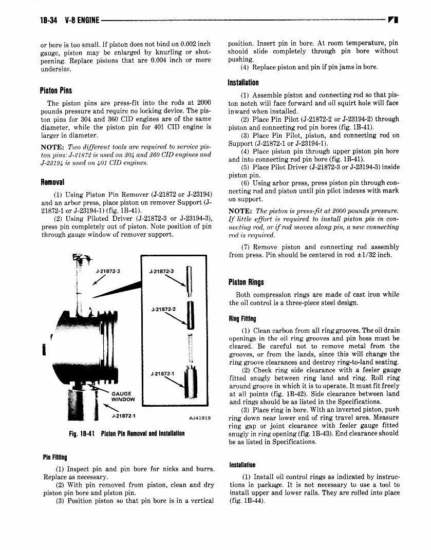
1B-34 V-B ENGINE
or boreis too small. If pistondoesnot bind on 0.002 inch
gauge, piston may be enlarged by knurling or shot
peening.Replace pistons that are 0.004 inch ‘or moreundersize.
Piston PinsThe piston pins are press-fit into the rods at 2000
poundspressureand requireno locking device.The piston pins for 304 and 360 CID enginesare of the samediameter, while the piston pin for 401 CID engine islarger in diameter.
NOTE: Two different tools are required to servicepistonpins:J-21872is usedon 304 and 360 GID enginesandJ-23194is usedon 401 GID engines.
Removal1 Using Piston Pin RemoverJ-21872or J-23194
and an arbor press,placepiston on removerSupportJ21872-1 or J-23194-1fig. 1B-41.
2 Using Piloted Driver J-21872-3 or J-23194-3,presspin completelyout of piston. Note position of pinthroughgaugewindow of removersupport.
I
Pin Fitting
Fig. 1B-41 Piston Pin Removal and Installation
1 Inspect pin and pin bore for nicks and burrs.Replaceas necessary.
2 With pin removedfrom piston, clean and drypistonpin boreandpistonpin.
3 Position piston so that pin bore is in a vertical
position. Insert pin in bore. At room temperature,pinshould slide completely through pin bore withoutpushing.
4 Replacepistonandpin if pin jamsin bore.
Installation1 Assemblepiston and connectingrod so that pis
ton notch will face forward and oil squirt hole will faceinward when installed.
2 PlacePin Pilot J-21872-2or J-23194-2throughpistonandconnectingrod pin boresfig. 1B-41.
3 PlacePin Pilot, piston, and connectingrod onSupportJ-21872-1or J-23194-1.
4 Place piston pin through upper piston pin boreandinto connectingrod pin borefig. 1B-41.
5 PlacePilot Driver J-21872-3or J-23194-3insidepistonpin.
6 Usingarbor press,presspistonpin throughconnectingrod andpiston until pin pilot indexeswith markon support.
NOTE: The pistonis press-fitat 2000poundspressure.If little effort is required to install pistonpin in connectingrod, or if rod movesalong pin, a new connectingrod is required.
7 Remove piston and connectingrod assemblyfrom press.Pin should becenteredin rod ± 1/32 inch.
Piston RingsBoth compressionrings are madeof cast iron while
the oil control is a three-piecesteel design.
Ring Fitting1 Clean carbonfrom all ring grooves.Theoil drain
openingsin the oil ring groovesand pin bossmust becleared. Be careful not to remove metal from thegrooves, or from the lands, since this will changethering grooveclearancesand destroyring-to-landseating.
2 Check ring side clearancewith a feeler gaugefitted snugly between ring land and ring. Roll ringaroundgroovein which it is to operate.It mustfit freelyat all points fig. 1B-42. Side clearancebetweenlandandrings shouldbe as listed in the Specifications.
3 Placering in bore. With an invertedpiston, pushring down nearlower end of ring travel area.Measurering gap or joint clearancewith feeler gaugefittedsnugly in ring openingfig. 1B-43.End clearanceshouldbe as listed in Specifications.
Installation1 Install oil control rings as indicatedby instruc
tions in package. It is not necessaryto use a tool toinstall upperand lower rails. They are rolled into placefig. 1B-44.
VI

V-B ENGINE 1B-35
2 Install lower compressionring using ring installer to expandring aroundpiston.
NOTE: Make certain upper md lower compressionrings are not installed upsidedown, Fiqure 1B-45showstypical rin,q markings to indicate the top side ofthe ring.
60122
Fig. 18-44 Installing Upper and lower Rails
/4: /2/2 AJ41913
Fig. 1B-45 Typical Piston Ring Markings
3 Install upper compressionring using ring installer to expandring aroundpiston fig. 1B-46.
VI
IAJ41946
Fig. 18-42 Ring Side Clearance Measurement
Fig. 18-43 Ring Gap Measurement
RINGINSTALLER AJ41914
Fig. 1 B-46 Compression Ring Installation

18-36 V-B ENGINE
CRANKSHAFT
The crankshaftis counterweightedandbalancedindependently. The componentparts of the crankshaftassemblyare individually balanced,andthenthe completeassembly is balancedas a unit; therefore, service replacementdampers,crankshafts,flywheels,torqueconverters,andclutch componentsmay bereplacedwithoutrebalancingthe assembly.
There are five main bearingsandfour connectingrodjournals. The end thrust is controlled by No. 3 mainbearing.
The rearmain bearingoil sealis protectedfrom excessive oil by a slinger which is a machinedpart of thecrankshaft.
NOTE: On automatic transmissionequippedengines,the torque converterand converterflexplate must bemarkedprior to removaland ‘installed in this positionupon a..ssembly.
Removal or Replacement
If the crankshaftis damagedbeyondreconditioning,itmust be replaced. Use the proceduresoutlined underCylinder Block earlier in this sectionfor removal andinstallationof the crankshaft.
Checking End PlayThe crankshaftend play is controlled at the No. 3
main bearingwhich is flangedfor this purpose.1 Attach a dial indicator to crankcaseadjacentto
No. 3 main bearing.2 Setdial indicatorpushrod on faceof an adjacent
counterweightfig. 1B-47.
VI
3 Pry crankshaftfore and aft.4 Readdial indicator. End play is the differenceof
high andlow readings.5 If end play is incorrect accordingto Specifica
tions,inspectcrankshaftthrustfacesfor wear.If no endplay is apparent,replacethrustbearingandrecheckendplay. If end play is still outside of specifications,thecrankshaftmust be replaced.
NOTE: When replacing the thrust bearings, pry thecrankshaftfore and aft to align the thrustfacesof thebearings.
Measuring Main Bearing Journal with Micrometer Crankshaft Removed
1 Wipe main bearingjournal clean.2 Using a micrometer,measurejournal diameter
at a numberof points. Note difference betweenmaximum and minimumdiameters.
3 Refer to Specificationsfor maximumallowabletaperandout-of-round.
4 Comparemaximumreadingobtainedwith journal diameterslisted in bearingfitting chart.
5 Select inserts required to obtain specifiedbearing clearance0.0017 to 0.0020 inch desiredon No. 1through No. 4 main bearingsand 0.0025 to 0.003 inchdesiredfor the rearmain bearing.
Crankshaft Main BearingsThe main bearingcaps are numberedfront to rear
from 1 through 5, with an arrow to indicate forwardposition. The upper main bearinginserts are groovedwhile the lower insert surfacesare smoothfor the 304-360 CID engines.
NOTE: The 401 GID engine has a groove in both theupperand lower insert.
Eachbearingis selectfit to its respectivejournal toobtain the desiredoperatingclearance.In production,the select fit is obtained by using various sized colorcoded bearing inserts as shown in the Main BearingFitting Chart. The bearing color code appearson theedgeof the insert.
NOTE: Bearingsizeis stampedon. productioninserts.
The main bearingjournal size is identified in production by a color codedpaint mark on the adjacentcheektoward the flangedrear end of the crankshaftexceptfor the rear main journal. The paint mark for the rearmain journal is on the crankshaftrearflange.
Usethe BearingFitting Chart to selectproperbearinginserts to obtain the specifiedbearingclearance0.0017to 0. 0020 inch desiredon No. 1 through No. 4 mainbearingsand 0.0025 to 0.003 inch desiredfor the rearmain bearing.
Whenrequired,different sizedupperandlower bearing insertsmay be usedas a pair. A standardsizeupperFig. 18-47 Crankshaft End Play Measurement

Main Bearing Fitting Chart Inches
V-B ENGINE 1B-37
Crankshaft Main Bearing JournalColor Code and Diameter in
Inches Journal Size
Bearing Color Code
Upper Insert Size Lower Insert Size
Yellow -2.7489 to 2.7484 StandardOrange -2.7484 to 2.7479 0.0005 UndersizeBlack -2.7479 to 2.7474 0.001 UndersizeGreen -2.7474 to 2.7469 0.0015 UndersizeRed -2.7389 to 2.7384 0.010 Undersize
Yellow - StandardYellow - StandardBlack - .001-inch UndersizeBlack - .001-inch UndersizeRed - .010-inch Undersize
Yellow - StandardBlack - .001-inch UndersizeBlack - .001-inch UndersizeGreen - .002.inch UndersizeRed - .010-inch Undersize
insert may be used in combination with a 0.001-inchundersizelower insertto reduceclearanceby 0.0005inch1/2 thousandthof an inch.
Example:
Insert Correct Incorrect
Upper Standard Standard
Lower 0.001-inchundersize
0.002-inchundersize
70242
NOTE: Whenservicingupperand lower insertsof dif.ferent sizes, install all samesize inserts togethereitheron the top upper or bottom lower. Neverusebearinginserts with greater than 0.001-inch thfferencein pairs.
Servicereplacementbearing inserts areavailableaspairs in the following sizes:standard,0.001-inchundersize, 0.002-inch undersize, 0.010-inch undersize, and0.012-inch undersize.The size is stampedon back ofservicereplacementinserts.
NOTE: The 0.002 and 0.012-inch undersizeinserts arenot ‘used in production.
Removal and Inspection
This proceduremay be usedto check main bearingswith enginein vehicle.
1 Drain engineoil andremovepan.2 Removemain bearingcapandinsert.3 Inspect bearing insert for abnormal wear or
damage.4 If either condition exists, both upperand lower
inserts must be replaced.Refer to MeasuringBearingClearancewith Plastigage,as described later in thissection,to selectbearinginsertsrequired to obtain specified bearingclearance.
5 Inspect crankshaft main journal. If damaged,eitherreconditionor replacecrankshaft..
6 Remove upper insert by loosening all of theother bearingcapsandinsertinga cotter pin about1/2-
60273
inch long in the crankshaftoil hole. Headof pin shouldbe large enoughso that it will not fall into oil hole, yetthinner thanbearingfig. 1B-48.
BEND HEAD TO FOLLOWCONTOUR OF JOURNAL
7/64-INCH COTTER PIN
60763
Fig. 18-48 Upper Main Bearing Insert Removal Tool
7 With pin in place, rotate shaft so that upperbearinginsert will rotatein the directionof its locatingtang.
8 Removeandinspectremainingbearingsin samemannerfig. 1B-49.
Measuring Main Bearing Clearance with Plastigage Crankshaft Installodj
NOTE: Checkeachbearing clearanceoneat a time. Allother bearingsmustremain, tightened.
1 Removemain bearingcapandinsert.2 Wipe insert and exposedportion of the crank
shaft journal clean.3 Placea strip of Plastigageacrossfull width of
bearinginsert.4 Install bearingcapandtightenretainingbolts to
100 foot-poundstorque.5 Removebearingcap and determineamount of
clearanceby measuringwidth of compressedPiastigagewith scaleon Plastigageenvelope0.0017to 0.0020inch
VI

1B-38 V-B ENGINE
LOWER
HEAVIER WEARPATTERN ONLOWER BEARING
Fig. 18-49 Normal Main Bearing Wear Pattern
clearancedesiredon No. 1 through No. 4 main bearingsand 0.0025to 0.003 inch desiredfor the rear main bearing fig. 1B-50.
NOTE: The Piastigageshould maintain the samesizeacross the entire width of the insert. If size varies, thismay indicate a taperedjournal or dirt trapped behindthe insert.
6 If correctclearanceis indicated,bearingfittingis not necessary.Remove Plastigagefrom crankshaftand bearing.Proceedto Installation.
7 If oil clearanceexceedsspecification,install pairof 0.001-inch undersizebearinginserts and checkclearanceas describedin steps3 through 6.
8 Clearance indicated with 0.001-inch undersizebearing installedwill determineif 0.001-inchundersize
inserts or some other combinationwill providecorrectclearance.For example; if clearancewas 0.0035 inchoriginally, a pair of 0.001-inch undersizeinserts wouldreduceclearanceby 0.001 inch. Oil clearancewould be0.0025inch andwithin specification.A 0.002-inchundersixe insert half and a 0.001 inch undersizehalf woudireduce this clearancan addtional 0.0005 inch and oilclearancewould be 0.002-inch.
CAUTION: Neveruse a pair of inserts which differmore than one bearing size as a pair. For example,donotusea standardupperand0.002 inch undersizelower.
9 If oil clearanceexceedsspecificationusing0.002inch undersizebearings, measurecrankshaftjournalwith micrometer. If the journal size is correct, thecrankshaftboreof the cylinder block maybe misalignedwhich requires cylinder block replacement.If journalsize is incorrect, crankshaftmustbe replaced.
Measuring Main Bearing Journal with Micrometer Crankshaft Removed1 Wipemain bearingjournal clean.2 Measure journal diameter with micrometer.
Note difference between maximum and minimumdiameters.
3 Refer to Specificationsfor maximumallowabletaperand out-of-round.
4 Comparemaximumreadingobtainedwith journal diameterslisted in bearingfitting chart.
5 Selectinsertsrequiredto obtain specifiedbearing clearance.Correctclearanceis 0.0017 to 0.0020inchon No. 1 throughNo. 4 main bearingsand0.0025to 0.003inch for rearmain bearing.
Installation1 Lubricate bearingsurfaceof each insert with
cleanengineoil.2 Loosenall main bearingcaps.3 Install main bearingupperinserts.4 Install main bearingcapsand lower inserts.
Tightenretainingbolts evenly to 100foot-poundstorquein steps of 30, 60, 90 and 100 foot-pounds torque increments,turningcrankshaftat each stepto determineif crank rotatesfreely. If crank does not rotatefreely,checkinsertsfor properinstallationandsize.
5 After installation,turn crankshaftto check forfreeoperation.
6 Install oil pan using new gasketsand seals.Tighten drain plug securely.
7 Fill crankcaseto specifiedlevel with newoil.
FLYWHEEL AND STARTER RING GEAR ASSEMBLYThe starterring gear is a separateitem only on ve
hicles with manualtransmission.The starterring gearis weldedto and balancedas part of the converterdriveplateon vehicles with automatictransmission.The entire drive plate/ringassemblymustbe replacedon automatic transmissionequippedvehicles.Thetransmissionmustbe removedto servicethe ring gear.
UPPER
NO WEAR INTHIS AREA
LOW AREAIN BEARING
VI
Fig. 18-50 Main Bearing Clearance Measurement
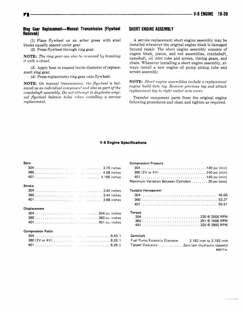
VI V-B ENGINE 1 B-39
Ring Gear Replacement-Manual Transmission FlywheelRemoved
1 Place flywheel on an arbor press ‘with steelblocks equallyspacedundergear.
2 Pressflywheel throughring gear.
NOTE: The ring gear can also be removedby breakingit with a chisel.
3 Apply heatto expandinsidediameterof replacement ringgear.
4 Pressreplacementring gearontoflywheel.
NOTE: On manual transmission,the flywheel is balancedas an individual componentand also aspart of thecrankshaftassembly.Do not attemptto duplicateoriginal flywheel balance holes when installing a servicereplacement.
SHORT ENGINE ASSEMBLY
A servicereplacementshort engineassemblymay beinstalledwheneverthe original engineblock is damagedbeyond repair. The short engine assemblyconsists ofengine block, piston, and rod assemblies,crankshaft,camshaft,oil inlet tube and screen,timing gears,andchain. Wheneverinstalling a short engineassembly,always install a new engine oil pump pickup tube andscreenassembly.
NOTE: Shortengineassembliesinclude a replacementenginebuild date tag. Removeprevious tag and attachreplacementtag to right rockerarm cover.
Transfer componentparts from the original enginefollowing proceduresandcleanandtightenas required.
V-8 Engine Specifications
304360401
Compression Pressure
304 l4Opsi360 2V or 4V 140 psi401.. l4Opsi
Maximum Variation Between Cylinders 20 psi
Taxable Horsepower304360401 55.51
Displacement304360401
304 Cu. inches360 cu. inches401 cu. inches
Torque304 220 @ 2000 RPM360 251 @ 1600 RPM401 320 @ 2800 RPM
Compression RatioCamshaftFuel Pump Eccentric Diameter 2.182 inch to 2.192 inchTappet Clearance Zero lash hydraulic tappets
60271A
Bore304 3.75 inches360 4,08 inches401 4.165 inches
Stroke3.44 inches3.44 inches3.68 inches
mmmmmmmm
45.0053.27
304360 2V or 4V
8.40:1
4018.25:18.25:1

1B-40 V8 ENGINE
V-8 Engine Specifications Continued
CamshaftContinuedEnd Play Zero engine operatingBearing Clearance 0.001 inch to 0.003 inch
0.0017-0.0020 inch preferred
Bearing Journal DiameterNo. 1 2.1195 inch to 2.1205 inchNo. 2 2.0895 inch to 2.0905 inchNo. 3 2.0595 inch to 2.0605 inchNo. 4 2.0295 inch to 2.0305 inchNo. 5 1.9995 inch to 2.0005 inch
Base Circle Runout 0.00 1 maximum
Cam Lobe Lift304/360 0.266 inch401 0.286 inch
Intake Valve TimingOpens 304/360 14.75° BTDC
401 25.57°BTDC
Closes 304/360 68.75° BTDC401 90.75°BTDC
Exhaust Valve TimingOpens 304/360 56.75° BBDC
401 80.800BBDCCloses 304/360 26.75° ATDC
401 42.75°ATDC
Valve Overlap304/360 41.50°401 68.32°
Intake Duration304/360 263.50°407 296.32°
Exhaust Duration304/360 263.50°401 303.55°
Connecting RodsTotal Weight Less Bearings
304/360 681 to 689 grams401 794 to 802 grams
Total Length Center-to-Center304/360 5.873 inch to 5.877 inch401 5.856 inch to 5.860 inch
Bearing Clearance 0.001 inch to 0.003 inch0.0020-0.0025 inch preferred
Side Clearance 0.006 inch to 0.018 inchMaximum Twist 0.0005 inch per inchMaximum Bend 0.001 inch per inch
Crankshaft
End PlayMain Bearing Journal Diameter
No. 1,2,3,4Rear Main
Main Bearing Journal Width304/360
No. 1No.2No. 3No. 4No. 5
4011.244 inch to 1.269
1.222 inch to 1.2321.273 inch to 1.2751.222 inch to 1.2321.202 inch to 1.217
Main Bearing ClearanceNo. 1,2,3,4
Rear Main
VI
No. 5 0.002 inch to 0.003 inch0.0025 inch preferred
Connecting Rod Journal Diameter304/360 2.0934 inch to 2.0955 inch401 2.2464 inch to 2.2485 inch
Connecting Rod Journal Width304/360 1.998 inch to 2.004 inch401 1.846 inch to 1.852 inch
Connecting Rod BearingClearance 0.001 inch to 0.003 inch
0.0020-0.0025 inch preferredMaximum Taper All Journals 0.0005 inchMaximum Out-of-Round All Journals 0.0005 inch
Cylinder BlockDeck Height 9.205 inch to 9.211 inch
Deck Clearance304/360 0.0145 inch below block401 0.0045 inch below block
Maximum Cylinder Taper 0.005 inchMaximum Cylinder Out-of-Round 0.003 inchTappet Bore Diameter 0.9055 inch to 0.9065 inchCylinder Block Flatness 0.001/1 inch; 0.002/6 inch;
0.008 inch maximum
0.003 inch to 0.008 inch
2.7474 inch to 2.7489 inch2.7464 inch to 2.7479 inch
1.2635 inch to 1.26951.246 inch to 1.2481 .273 inch to 1 .2751.246 inch to 1.2481.2l5inchtol.217
No. 1No.2No. 3No. 4No. 5
inchinchinchinchinch
inchinchinchinchinch
0.001 inch to 0.003 inch0.00 17-0.0020 inch preferred
602718

VI
V-8 Engine Specifications Continued
V-B ENGINE 1B-41
Cylinder Head
Combustion Chamber Volume304 57.42 to 60.42 cc360/401 . 58.62to61.62cc
Valve Arrangement Eli EEl-I EValve Guide ID Integral 0.3735 nch to 0.3745 inchValve Stem-to-Guide Clearance . . . . 0.001 rich to 0.003 inchIntake Valve Seat Angle 30°Exhaust Valve Seat Angle 4450
Valve Seat Width 0.040 nch to 0.060 inchValve Seat Runout 0.0025 inch maximumCylinder Head Flatness 0.001 ii inch; 0.002/6 inch;
0.008 inch maximum
Piston Ring Side Clearance304
No. 1 0.0015 inch to 0.0035 inch0.0015 inch preferred
No. 2 0.0015 inch to 0.003 inch0.0015 inch preferred
Oil Control 0.0011 inch to 0.008 inch360/401
No. 1 0.0015 inch to 0.003 inch0.0015 inch preferred
No. 2 0.00 15 inch to 0.0035 inch0.0015 inch preferred
Oil Control 0.000 inch to 0.007 inch
Lubrication SystemEngine Oil Capacity
Normal Operating Pressure.
Oil Pressure ReliefGear-to-Body Clearance
Gear End ClearanceFeeler Gauge Method
Plastigage Method
4 quarts
add 1 quart with filter change13 psi at 600 rpm;
37 To 75 psi at 1600 rpm+75 psi maximum
0.0005 inch to 0.0025 inch0.0005 inch preferred
0.004 inch to 0.008 inch0.008 inch preferred
0.002 inch to 0.006 inch0.002 inch preferred
1.526 inch to 1.578 inch1.485 inch to 1.484 inch
No. 1
3.328 inch to 3.333 inch3.329 inch to 3.339 inch
3.749 inch to 3.759 inch3.7 15 inch to 3.725 inch
inch to 3.720 inch
Weight Less Pin506 to 510 grams
601 to 605 grams590 to 594 grams
Piston Pin Bore CL - to Piston Top304/360 1 .599 inch to 1.603 inch401 1,506 inch to 1.510 inch
Piston Ring Gap Clearance
0.0010 inch to 0.001 8 inch0.0014 rich preferred
0.0012 inch to 0.0020 inch0.0016 inch preferred
No. 1 and No.2 0.010 inch to 0.020 inch0010-0.0012 inch preferred
Piston Pin Diameter
304/360 0.9308 inch to 0.9313 inch401 1.0009 inch to 1.0012 inch
Piston Pin Bore Diameter304/360 0.9288 inch to 0.9298 inch401 0.9988 inch to 0.9998 inch
Piston-to-Pin Clearance 0.0003 inch to 0.0005 inch0.0005 inch preferred loose
Rocker Arms, Push Rods, and Tappets
Rocker Arm Ratio 1 .6: 1Push Rod Length 7.790 inch to 7.810 inchPush Rod Diameter 0.312 inch to 0.315 inchHydraulic Tappet Diameter 0.9040 inch to 0.9045 inchTappet-to-Bore Clearance 0.001 inch to 0.0025 inch
0.010 inch to 0.025 inch0.015 inch to 0.045 inch0.015 inch to 0.055 inch
0.010-0.020 inch preferred
Valves
Valve LengthTip-to-Gauge Dim. Line. .
Valve Stem DiameterStem-to-Guide Clearance
4.7895 inch to 4.8045 inch0.37 15 inch to 0.3725 inch
0.001 inch to 0.003 inch
Piston Ring Groove HeightNo. 1 and No. 2 0.0795 inch to 0.0805 inchOil Control 0.1880 inch to 0.1895 inch
Piston Ring Groove Diameter304
Gear Diameter
No. 1 and No. 2Oil Control
Gear Length
Pistons
360No. 1 and No. 2 3.624 inch to 3.629 inchOil Control 3.624 inch to 3.635 inch
401
304360401
No. 2Oil Control 3.7 10
Piston-to-Bore Clearance304/401
360
Oil Control Steel Rail304360401
6o2?1C

1B-42 V-B ENGINE
intake Valve Head Diameter304 1.782 inch to 1.792 inch360/401 2.020 inch to 2.030 inch
Intake Valve Face Angle 29°
Exhaust Valve Head Diameter304 1.401 inch to 1.411 inch360/401 1.675 inch to 1.685 inch
Exhaust Valve Face Angle 440
Valve SpringsFree Length 2.200 inch
Spring TensionValve Closed 80 to 88 pounds at 1-13/16 inchValve Open 210 to 216 pounds at 1-23/64 inch
Inside Diameter All 1.000 inch to 1.020 inch602710
Torque Specifications
Service In-Use Recheck Torques shouldpre-torqued item.
Air Injection Tube-to-ManifoldAir Pump-to-Bracket Pivot ScrewAir Pump Brackets-to-Engine-AC
Compressor or PedestalsAir Pump Adjusting Strap-to-Pump - . -Alternator Pivot Bolt or NutAlternator Adjusting BoltAlternator Mounting Bracket
Bolt-to-EngineAlternator Pivot Mounting
Bolt-to-HeadAutomatic Transmission-to-BlockCamshaft Gear Retainer ScrewCarburetor Adapter-to-Manifold
Screws-2VCarburetor Holddown NutsClutch Housing Spacer-to-Block
ScrewsClutch Housing-to-Block ScrewsConnecting Rod Bolts Nuts
Crankshaft Pulley-to-DamperCylinder Head CapscrewsCylinder Head Cover ScrewsDistributor Clamp ScrewDrive Plate-to-Converter ScrewEGR Valve-to.ManifoldExhaust Manifold BoltsExhaust Pipe-to-Manifold NutsFan and Hub Assembly BoltsFlywheel or Drive Plate-to-Crankshaft -Front Support Cushion
Bracket-to-Block Screw
be used for checking a
ServiceService In-UseSet-To Recheck
Torque Torque
38 30to4520 15to22
18 to 2815 to 2220 to 3515 to 20
28 23to30
33 30to3528 22to3830 25to35
14 12to1514 12to15
12 9to1527 22to3033 30to35
304 & 360 304 & 36039401 35to40401
18 to 28100 to 120
42 to 58 in-lb10 to 1820 to 25
13 9to1825 20to3020 15to2518 12to25
105 95to120
35 25to40
Front Support Cushion-to-BracketFront Support
Cushion-to-FrameFuel Pump Screws
Oil Pan Screws1/4 Inch -205/l6lnch-18
ServiceService In-UseSet.To RecheckTorque Torque
33 27to38
33 27to3716 13to19
33 28to38
7 4to943 37to47100 90to105
55 in-lb 45to65 in-lb
7 5to911 9to1328 22to3523 18to2843 37to4728 25to3533 27to3848 40to55
V-8 Engine Specifications Continued
VI
Service Set-To Torques should be used when assembling components.
25202818
Idler Pulley BearingShaft-to-Bocket Nut
Idler Pulley Bracket-to-FrontCover Nut
Intake Manifold ScrewsMain Bearing CapscrewsOil Pump Cover Screws
Oil Relief Valve CapPower Steering Pump Adapter Screw -Power Steering Pump Bracket Screw . . -Power Steering Pump Mounting Screw -Rear Insulator Bracket-to-Trans. Bolt -Rear Support Insulator-to-Bracket Nut -Rear Support Cushion-to-Crossmember
Screw NutRocker Arm CapscrewSpark PlugsStarter Motor to Bell Housing Screws -Thermostat Housing ScrewThrottle Valve Rod Adjusting Screw . . -
Timing Case Cover-to-BlockVibration Damper ScrewWater Pump Screws
23110
50 in-lb1322
1819281813
40 in-lb2590
48 in-lb
12 to 25l6to 2622 to 3313 to 2510 to 18
30 to 50 in-lb18 to 33
80 to 10040to55 in-lb
All torque values given in foot-pounds with dry fits unless otherwise specified.
Refer to the Standard Torque Specifications and Capscrew MarkingsChart in Section A of this manual for any torque specifications notlisted above.
60272

VI
J-22534-1VALVE SPRINGREMOVER ANDINSTALLER
t1utiJ-21872 - 304-360 CID SHOWNJ-23194 -401 CIDPISTON PIN REMOVER AND INSTALLER
DIAL INDICATCLAMP AND ROD
J-8520DIAL INDICATOR SET0-1 INCH -.001 INCH GRADUATION
J-6042-1, 4, 5VALVE GUIDE REAMERS
oIL FILTER WRENCH
V-8 ENGINE 1B-43
J-21791VIBRATION DAMPERREMOVER
J-26562TIMING CASE COVEROIL SEAL INSTALLER
SJ-5790HYDRAULIC VALVELIFTER TESTER
J-8056VALVE AND CLUTCHSPRING TESTER AJ41951
Special Tools
TECHNICAL BULLETIN REFERENCE
Date TB No. Subject Changes Information on Page No.


![Unit 1B - HPT · design entwerfen, konstruieren; Entwurf, Muster 1B device Vorrichtung 1B dimension [ˌdaɪˈmen(t)ʃən] Abmessung 1B district Bezirk 1B drawing Zeichnung 1B drill](https://img.dokumen.tips/doc/110x75/6004851a49508c087b3c11bf/unit-1b-hpt-design-entwerfen-konstruieren-entwurf-muster-1b-device-vorrichtung.jpg)