Embed Size (px)
Citation preview

®
8 2002 IBM Corporation
V5R2 Hardware
J02_HDWAug20.PRZ 108/22/02-9:03 AM

8 2002 IBM Corporation
ibm.com/eserver/iseries
Hardware Announcements
New Model 890
Model 830 and Model 840 Enhancements
New I/O features
J02_HDWAug20.PRZ 208/22/02-9:03 AM
8 2002 IBM Corporation
ibm.com/eserver/iseries
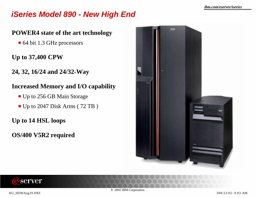
iSeries Model 890 - New High End
POWER4 state of the art technology64 bit 1.3 GHz processors
Up to 37,400 CPW
24, 32, 16/24 and 24/32-Way
Increased Memory and I/O capabilityUp to 256 GB Main Storage
Up to 2047 Disk Arms ( 72 TB )
Up to 14 HSL loops
OS/400 V5R2 required
J02_HDWAug20.PRZ 308/22/02-9:03 AM

8 2002 IBM Corporation
ibm.com/eserver/iseries
Notes: iSeries Model 890 - New High EndWith its 32-way POWER4 processor, the Model 890 is 1.85 times higher CPW rating than the largest Model 840 24-way server today. Other capacities of the Model 890 are also expanded to match its performance, with main storage and number of DASD arms more than doubled, more details can be found later in this presentation . The Model 890 extends the iSeries performance and capacity for the next generation of e-business.
J02_HDWAug20.PRZ 408/22/02-9:03 AM
8 2002 IBM Corporation
ibm.com/eserver/iseries
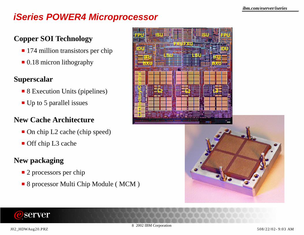
iSeries POWER4 Microprocessor
Copper SOI Technology174 million transistors per chip
0.18 micron lithography
Superscalar8 Execution Units (pipelines)
Up to 5 parallel issues
New Cache ArchitectureOn chip L2 cache (chip speed)
Off chip L3 cache
New packaging2 processors per chip
8 processor Multi Chip Module ( MCM )
J02_HDWAug20.PRZ 508/22/02-9:03 AM
8 2002 IBM Corporation
ibm.com/eserver/iseries
Notes: iSeries POWER4 Microprocessor -1POWER4 cannot be considered only a chip, but rather an architecture of how a set of chips are designed together to realize a system. As such, POWER4 can be considered a technology in its own right. In that light, systems are built by interconnecting POWER4 chips to form up to 32-way symmetric multiprocessors. The interconnect topology, referred to as a Distributed Switch, is new to the industry. Finally, no system discussion would be complete without some view of the reliability, availability and serviceability (RAS) features and philosophy incorporated into POWER4 systems. The RAS design is pervasive throughout the system and is as much a part of the design.The POWER4 design can handle a varied and robust set of workloads. This is especially important as the e-business world evolves and data intensive demands on systems merge with commercial requirements. The need to satisfy high performance computing requirements with its historical high bandwidth demands and commercial requirements with its data sharing and SMP scaling requirements dictated a single design to address both environments. The chip as it is shown on this foil has two processors on board. Included in what we are referring to as the processor are the various execution units and the split first level instruction and data caches. The two processors share a unified second level cache (L2), also onboard the chip, through a Core Interface Unit. The Core Interface Unit is a crossbar switch between the L2, implemented as three separate, autonomous cache controllers, and the two processors. Each L2 cache controller can operate concurrently and feed 32 bytes of data per cycle. The Core Interface Unit connects each of the three L2 controllers to either the data cache or the instruction cache in either of the two processors.The directory for a third level cache (L3) and logically its controller are also located on the POWER4 chip (L3 Directory Control in the picture). The actual L3 is on a separate chip. A separate functional unit, referred to as the Fabric Controller, is responsible for controlling data flow between the L2 and L3 controller for the chip and for POWER4 communication. The GX controller is responsible for controlling the flow of information in and out of the system. Typically, this would be the interface to an I/O Tower attached to the system. But, with the POWER4 architecture, this is also where an interface to a switch for clustering multiple POWER4 nodes can be attached (interconnect POWER4 nodes in a Multi-node configuration). A GX controller is the name for the chip that controls the I/O bus. It connects to either the MCM interconnect switch to other MCM modules as described above or to the external I/O chip. This external I/O chip supports up to four intermediate I/O buses (HSL), which connect to a HSL-to-PCI bridge chip.
J02_HDWAug20.PRZ 608/22/02-9:03 AM

8 2002 IBM Corporation
ibm.com/eserver/iseries
Notes: iSeries POWER4 Microprocessor -2As shown in the other picture on the foil, four POWER4 chips are packaged on a single module to form an 8-way SMP. The 8-way MCM is the building block for the system. It is only available with four chips, each with its attached L3. A single processor on a chip has all of the L3 resources attached to the module, and the full L2 onboard the chip. Four such modules can be interconnected to form a 32-way SMP. To accomplish this, each chip has five primary interfaces. To communicate to other POWER4 chips on the same module, there are logically four 16-byte buses. Physically, these four buses are implemented with six buses, three on and three off. Abbreviations used in the picture of the processor chip: FPU = Floating Point Unit, ISU = Instruction Storage Unit, IDU = Input Data Unit, LSU = Logical Storage Unit, FXU = Fixed point (integer) Unit, BXU = Branch Execution Unit.IBM will continue to exploit its low-k technology employed in the 0.13 micron lithography process. IBM will aggressively increase processor frequencies to the 2+ GHz range while maintaining the system balance the current design offers. The current design introduces parallelism throughout the system so as to overcome the memory latencies resulting from high frequency operations. Enormous levels of bandwidth and concurrency contribute to superior performance across a broad range of commercial and high performance computing environments. These unprecedented performance levels are achieved by a total system design that exploits IBM’s leading technologies.
J02_HDWAug20.PRZ 708/22/02-9:03 AM

8 2002 IBM Corporation
ibm.com/eserver/iseries
Model 890 Available Processor Features
Base Processor Features24-Way #0197
29,300 Processor CPW
32-Way #019837,400 Processor CPW
Standard Processor Features16/24-Way #2487 CUoD
20,000 to 29,300 CPWProcessor Activation #1610Selected Interactive Feature
24/32-Way #2488 CUoD29,300 to 37,400 CPWProcessor Activation #1610Selected Interactive Feature
J02_HDWAug20.PRZ 808/22/02-9:03 AM

8 2002 IBM Corporation
ibm.com/eserver/iseries
Model 890 Additional Specifications
890 #0197 #0198 #2487 #2488Processors
Type24-wayPower 4
32-wayPower 4
16/24-wayPower 4
24/32-wayPower 4
CPW 29 300 37 400 20 000 / 29 300 29 300 / 37 400
Max. Main Storage 192 GB 256 GB 192 GB 256 GB
Max. CPW Interactive 0 0 20 200 31 700
Max. PCI slots 528 528 528 528
HSL loops 12 14 12 14
MAX. I/O Towers 47 47 47 47
Maximum DiskArms / Capacity 2047 / 72 TB 2047 / 72TB 2047 / 72TB 2047 / 72TB
Maximum LUNs / Capacity 2046 / 72TB 2046 / 72TB 2046 / 72TB 2046 / 72TB
Max. xSeries Servers / Adapters 32 / 32 32 / 32 32 / 32 32 / 32
Communication Lines Max. 480 480 480 480
Max. LAN cards 128 128 128 128
J02_HDWAug20.PRZ 908/22/02-9:03 AM

8 2002 IBM Corporation
ibm.com/eserver/iseries
Notes: Model 890 Additional SpecificationsThe importance of a balanced system configuration is maybe even more important then ever. Therefore, when creating a configuration for a Model 890 sizing the memory, the required number of disk arms or LUNs with related FC adapters (#2766) and the correct number of other I/O features that are necessary to achieve acceptable performance, must be installed. The number of physical I/Os that may be requested must be comfortably satisfied by the number of disk arms available on the system. A good estimation for the number of disk arms required on a given configuration can be found by using the ODAC (online disk arm calculator) tool available on the Internet at: http://www-912.ibm.com/supporthome.nsf/document/23035736From that page you can also link to: http://www-1.ibm.com/servers/eserver/iseries/perfmgmt/diskarm.htm where additional information can be found regarding the disk arm considerations on the iSeries server.Main Storage size is an other important issue. Since the Model 890 is using much faster processors with high caching capacities, the main storage rule of thumb for initial sizing should beat least around 4GB per used processor. For more exact sizing, the available sizing tools should be used preferably with the correct performance data available for the expected workload. The rules for main storage on the Model 890 are explained later in this presentation.
J02_HDWAug20.PRZ 1008/22/02-9:03 AM
8 2002 IBM Corporation
ibm.com/eserver/iseries
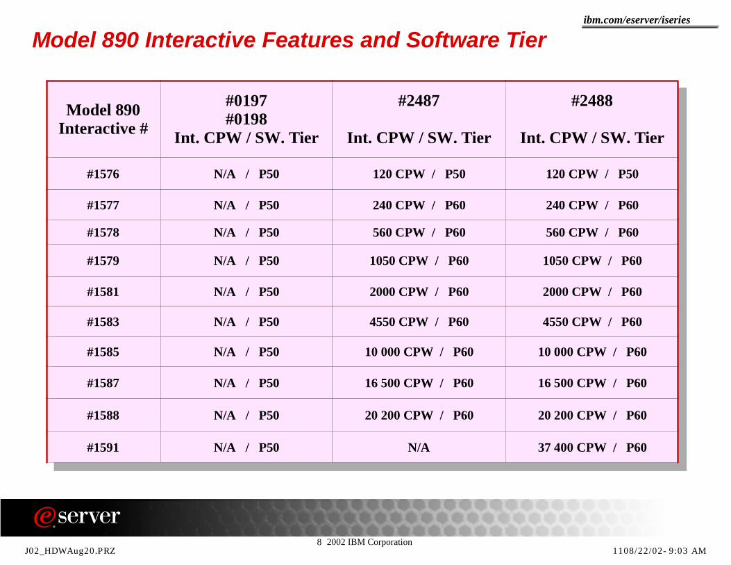
Model 890 Interactive Features and Software Tier
Model 890Interactive #
#0197#0198
Int. CPW / SW. Tier
#2487
Int. CPW / SW. Tier
#2488
Int. CPW / SW. Tier
#1576 N/A / P50 120 CPW / P50 120 CPW / P50
#1577 N/A / P50 240 CPW / P60 240 CPW / P60
#1578 N/A / P50 560 CPW / P60 560 CPW / P60
#1579 N/A / P50 1050 CPW / P60 1050 CPW / P60
#1581 N/A / P50 2000 CPW / P60 2000 CPW / P60
#1583 N/A / P50 4550 CPW / P60 4550 CPW / P60
#1585 N/A / P50 10 000 CPW / P60 10 000 CPW / P60
#1587 N/A / P50 16 500 CPW / P60 16 500 CPW / P60
#1588 N/A / P50 20 200 CPW / P60 20 200 CPW / P60
#1591 N/A / P50 N/A 37 400 CPW / P60
J02_HDWAug20.PRZ 1108/22/02-9:03 AM

8 2002 IBM Corporation
ibm.com/eserver/iseries
890 Processor Memory
Memory Card SizeAvailable Size: 4GB, 8GB, 16GB and 32GB
Trade in rules For upgrades within 890
For server upgrades to 890
e-Config support
Plugging rules applyInside and Outside slots (need different memory feature code )
890 Memory slots Minimum Maximum
#0197 #2487 6 16GB 192GB
#0198 #2488 8 24GB 256GB
J02_HDWAug20.PRZ 1208/22/02-9:03 AM

8 2002 IBM Corporation
ibm.com/eserver/iseries
There are eight new memory cards/features serving four capacity points of 4GB, 8GB, 16GB and 32GB. Each capacity point has both "inner" and "outer" card features. The correct plugging is to mirror images to fit physically different memory slots as follows:
For the inner slots (slots 0,1,2 and 3) the following feature codes must be used in pairs:4GB = #30208GB = #301516GB = #303532GB = #3017
For the outside slots (slots 4,5,6 and 7) the following feature codes must be used in pairs: 4GB = #30218GB = #301616GB = #303632GB = #3018
Additional plugging rules:Plug in pairs. Each pair must use identical features.On the Model 890 only two different sizes of memory cards are allowed. On top of this rule, when there are different size memory cards in a given configuration the different sizes must be adjacent in size. This means that you can't have for example 4GB and 16GB cards in a memory configuration. Allowed combinations are: all pairs of the same size, 4GB pairs with pairs of 8GB, 8GB pairs with 16GB pairs and pairs of 16GB with 32GB pairs.All slots should always be filled. Exception allowed for 16GB 24-Way and 24GB for 32-Way
* The smallest memory capacities are not recommended for most customer configurations and should only be used when performance degradation is not of concern, perhaps in environments with very low CPU utilization. With these capacities the inner slots must be filled first and then slots 4 and 5.
Notes: 890 Processor Memory
890 # slots Memory Capacity Offerings (GB)
#0197 #2487 6 16*, 24, 32, 40, 48, 64, 80, 96, 128, 160, 192
#0198 #2488 8 24*, 32, 40, 48, 56, 64, 80, 96, 112, 128, 160, 192, 224, 256
J02_HDWAug20.PRZ 1308/22/02-9:03 AM

8 2002 IBM Corporation
ibm.com/eserver/iseries
Model 890 and IBM's autonomic computing initiative: Making the best even better....Towards failure immunity and to avoid high impact outages
Retry and CorrectECC cache & memory (single bit correction)Chipkill memory (double bit correction)Memory predictive failure analysis
Mark and ReassignContinuous Memory ScrubbingBit steering memoryHot spare Memory Modules
Isolation and DeallocationDynamic processor deallocation
Detect and HealAutomatic IOP restart / reset / reloadAutomatic BUS reassignment
J02_HDWAug20.PRZ 1411/04/02-7:20 AM

8 2002 IBM Corporation
ibm.com/eserver/iseries
Notes: Model 890 and IBM's autonomic computing initiative: Making the best even better....IBM’s biggest proof point for ensuring reliability is the autonomic computing initiative. IBM's autonomic computing initiative is IBM’s blueprint for self-managing systems. Its goal is to use technology to manage technology, creating an intelligent, self- managing IT infrastructure. This minimizes complexity, giving customers the ability to manage environments that are hundreds of times more complex and more broadly distributed than exist today. This will enable increased utilization of technology, minimizing the spiraling pressure on critical skills, software and server/support costs. With the Model 890 a number of features that previously existed on the iSeries platform combined with a number of new failure immunity features make the iSeries as the platform (non-fault tolerant system such as the System 88) with the best low unplanned outage figures even better. Some of IBM's autonomic computing initiative features that can be found in the Model 890:Intelligent service processor that monitors the system’s health, detects problems, and can recommend actions before trouble arises by placing an automatic service call and initiate dynamic reconfiguration, if possible. Just as an example : in order to prevent an uncorrectable memory error from causing a system outage, the service processor is designed to initiate a deferred maintenance request on memory cards that have used their spare bits and are experiencing additional correctable errors (memory predictive failure analysis). Redundant power and cooling subsystems that provide complete redundancy in case of failures in power elements and cooling together with redundant internal battery features and optional dual line cords. Dynamic processor deallocation takes failing processors off-line and reassigns work to other processors without operator intervention. Chipkill memory protects the server for failures due to a failing memory chip. Using double-bit detection data integrity is maintained by detecting and reporting multiple errors beyond what the ECC (Error Correction Code) circuitry can correct. The memory chips are organized such that the failure of any specific memory module only affects a single bit within an ECC word (bit scattering) thus allowing for error correction and continued operation even in the presence of a complete chip failure where the chipkill method will be used. Memory scrubbing is the process of reading the contents of memory during idle time and checking and correcting any single-bit errors that have accumulated. These single-bit failures could be either solid (technology failures) or soft failures (intermittent errors caused by noise or other cosmic effects). If an error is detected, it is corrected by passing the data through the ECC logic that corrects the fault and then writes the corrected contents back to its memory address location. Dynamic bit steering is a technique that is using bit error thresholding to determine when spare memory modules within each bank of memory should be used to replace ones that have exceeded their error threshold value. Automatic bus reassignment: if a HSL link fails, the hardware will automatically initiate a HSL bus reassignment to route the data through the alternate path to its intended destination. Note: All other iSeries Models also have most of these features build-in.
J02_HDWAug20.PRZ 1511/04/02-7:20 AM

8 2002 IBM Corporation
ibm.com/eserver/iseries
Power requirements3-phase 200-240 Volt, 3-phase 380-415 Volt or 3-phase 480 Volt
45 Amps per phase maximum#0197 and #2487 : 5.946 KVA#0198 and #2488 : 7.754 KVA
Thermal output#0197 and #2487 : 19 280 BTU/hr#0198 and #2488 : 25 140 BTU/hr
Dimensions and WeightHeight 2025 mm (6 ft, 7.2 in); Depth 1494 mm (58.83 in) and Width 785 mm (30.91 in)
Special option available for reduced height when shipped (#0126)800 Kg (CEC), 1758 lbs
Perform Solution Assurance including Physical Planning
i890 power, heat, size, weight specifications
J02_HDWAug20.PRZ 1608/22/02-9:03 AM

8 2002 IBM Corporation
ibm.com/eserver/iseries
Notes: 890 Processor Physical Planning This foils shows important i890 physical planning metrics. The physical dimensions, weight , electrical, and heat dissipation (air conditioning required?) "specifications" must be properly planned for. You can find important information in Information Center as shown below.
See the following foils for more information.
J02_HDWAug20.PRZ 1708/22/02-9:03 AM

8 2002 IBM Corporation
ibm.com/eserver/iseries
Model 890 Physical Planning Additional Considerations
HSL Ports and CablingHSL-2
HSL-2 to HSL
HSL-2 Adapter slots and HSL-2 Adapters
Copper and Optical HSL Adapter combinations
No SPD support on the Model 890
Dual Power Cords
Base I/O tower (#9094) options and accessoriesContains three busses, one on each Multi-Adapter Bridge
#8093 1.8m rack with optional #0574
#5107 or #5117 for 30 disk unit expansion
HSL-2, Power, JTAG and VPD/SPCN Cables
DVD-RAM required
J02_HDWAug20.PRZ 1808/22/02-9:03 AM
8 2002 IBM Corporation
ibm.com/eserver/iseries
Notes: Model 890 Physical PlanningFor the new Model 890, planning for installation is key. Carefully consider the environmental requirements the Model 890 and start looking for a good site early. Given the height and the weight of the model 890 ,make sure your location is large enough and that the floor will support the weight of the system. Consider the space for the service clearance required. Take care about the way the system will moved into its final position, measure across halls, doorways, and elevators. If necessary order feature 0126.When ordered with feature 0126, the Model 890 is shipped in two pieces to be fully assembled at the customers location. The two shipped parts will then be 350mm and 1675mm high respectively, thus making them easier to handle and moved into the designated space.For the Model 890 there are supplemental considerations regarding the heat generated by the system. The thermal output of the Model 890 is 3 times the output of the 840 Model and almost 5 times the thermal output generated by a Model 830.For HSL cabling, you must be aware of the fact that all copper HSL ports on the Model 890 servers are HSL type 2 ports. The copper HSL cables running from the HSL ports to 5074 / 5079 / 0574 / 5078 or 0578 must be HSL-2 to HSL-cables. See backup foils for details on HSL adapters and HSL cables available for all different servers.You can't connect SPD based hardware to the Model 890, there is no support for migration towers, this implies that it is impossible to have any type of SPD hardware on this iSeries server. For existing hardware replacement and possible conversions, seethe appropriate tables in the appendix for additional related information.There is a change in the layout of the PCI cage for the base I/O tower. There are three busses in the PCI cage of the #9094 Tower. Each individual Multi Adapter Bridge is now also a individual system bus. The number of PCI slots available for IOP and IOA PCI cards (14) stayed the same. The HSL adapter resides in slot C10. All PCI slots are 3.3 Volt and there are no 5 Volt slots available in the #9094. See #9090 slot layout in backup foils.Note: the Model 890 has a base ECS adapter feature #9793 (non-CIM) or #9794 (CIM), for details see the description of the #2793 and #2794 later in this presentation. There is no base disk adapter for the Model 890 and one must be on the order to drive the Load Source disk Unit and the required DVD-RAM.PowerThere is a 3-phase electrical input requirement for the Model 890. The system will function normally with a nominal input voltage in the range of 200-480 V, AC. There are special considerations for balancing the loads over the phases, for details look in the InfoCenter under chapter : "Phase imbalance and bulk power regulator configuration". There are always two power cords running of the Model 890 CEC. Circuit breaker ratings should be 60 A for the 200-240 Volt installations and 30 A for the other voltages. In countries where the specified circuit breaker ratings are not acceptable, use the nearest available rating.
J02_HDWAug20.PRZ 1908/22/02-9:03 AM

8 2002 IBM Corporation
ibm.com/eserver/iseries
New Base Processors and Capacity Upgrade on Demand
Model 830Base Processor Feature 0153
No Interactive Feature8-Way with 7350 processor CPW P30
CUoD Processor Feature 23494 to 8-Way with 4200 to 7350 CPWAdditional Processor activation #160570 CPW Interactive P30, higher P40
Model 840Base Processor features 0158 and 0159
No Interactive Feature#0158 12-Way with 12000 processor CPW P40#0159 24-Way with 20200 processor CPW P40
Minimum OS level for all new processor features is V5R1
J02_HDWAug20.PRZ 2008/22/02-9:03 AM
8 2002 IBM Corporation
ibm.com/eserver/iseries
Notes: New Base Processors and new CUoD The Model 830 and 840 processor range is expanded with a number of new features that bring much more flexibility and growth paths into the iSeries family. These new base processors are designed for compute-intensive workloads and to handle Application, Web serving and Domino workloads.Base processors do not include support for applications using 5250 programming interfaces (measured as 5250-Interactive CPW on iSeries servers). This means that a single interactive job is allowed to process normal systems operations work. However, when even a single job processes many interactions or when more than one job is active, the customer runs the risk of having significantly degraded performance for those jobs. If multiple interactive jobs are processing active work at or close to the same time, the customer has to be willing to accept that the responses for those jobs could be very slow. Basically the Base Processor servers were designed for customers to do no other than occasional systems management, while most systems management related activities can be performed via Operations Navigator.The Base processor features offer a fixed level of processor capacity. (no Capacity Upgrade on Demand (CUoD) and no 5250-interactive Feature)The new base processor features in both the models 830 and 840 provide a new growth path for the base processors as well as for the Dedicated Servers for Domino in the Model 820. See the migration section and the appendix of this presentation for additional information on upgrade paths. The software tier for these base processors is P30 for the 8-way Model 830 and P40 for the 12-way AND the 24-way Model 840. For a more detailed explanation of CUoD see notes for the next foil.
J02_HDWAug20.PRZ 2108/22/02-9:03 AM
8 2002 IBM Corporation
ibm.com/eserver/iseries
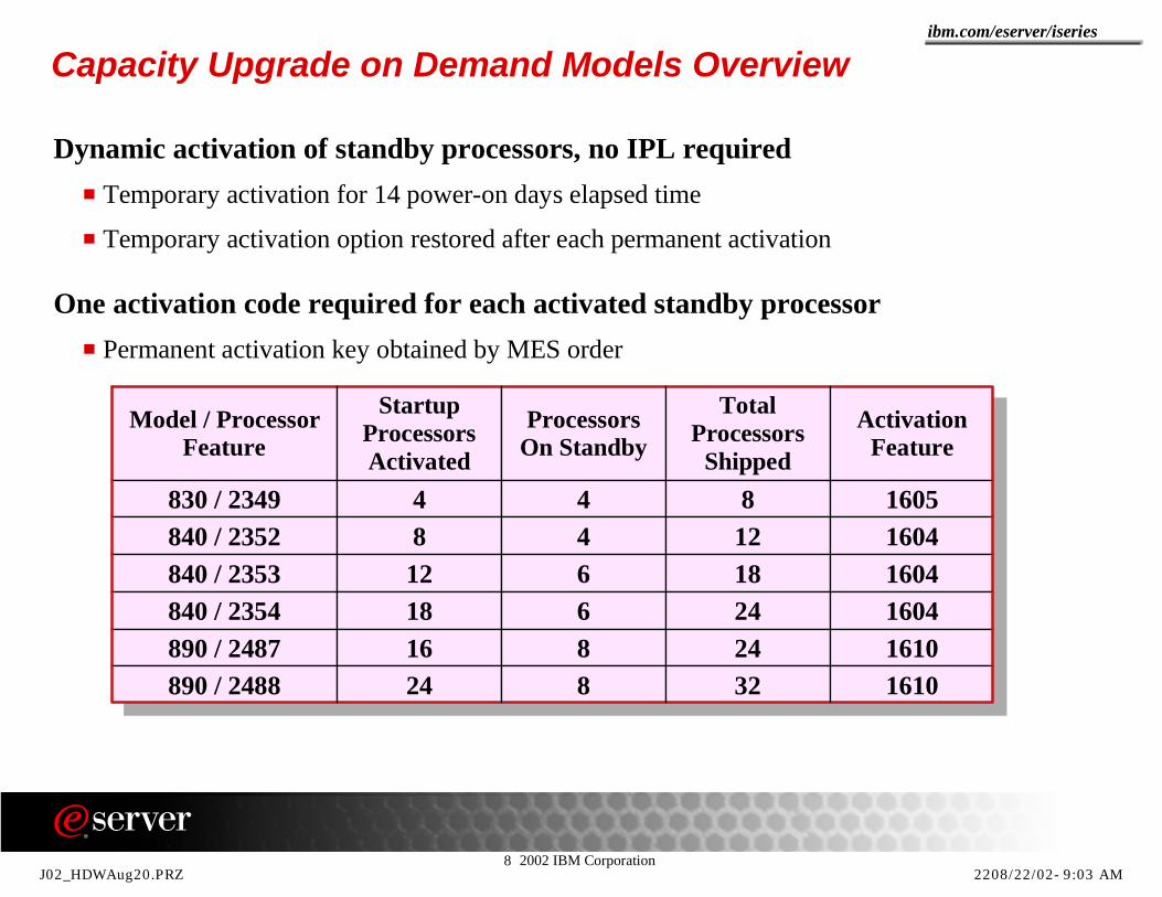
Capacity Upgrade on Demand Models Overview
Dynamic activation of standby processors, no IPL requiredTemporary activation for 14 power-on days elapsed time
Temporary activation option restored after each permanent activation
One activation code required for each activated standby processorPermanent activation key obtained by MES order
Model / Processor Feature
Startup Processors Activated
Processors On Standby
Total Processors
Shipped
Activation Feature
830 / 2349 4 4 8 1605840 / 2352 8 4 12 1604840 / 2353 12 6 18 1604840 / 2354 18 6 24 1604890 / 2487 16 8 24 1610890 / 2488 24 8 32 1610
J02_HDWAug20.PRZ 2208/22/02-9:03 AM

8 2002 IBM Corporation
ibm.com/eserver/iseries
Notes: Capacity Upgrade on Demand Models OverviewNow you can purchase iSeries Models 830, 840, and 890 with extra processor capacity built in. Each of these models can be purchased with a processor feature that offers a varying amount of capacity that can be turned on for a one-time trial period (Trial) or for long-term use (Per permanent). In the table you can find the different orderable options for the different models. The table also contains the number of processors that are shipped, the number of processors that are in standby mode and the number of processors that are activated by default when the server is shipped. You can add performance instantly on an iSeries server by using the provided trial capacity. All (not otherwise selectable) of the standby processors can be activated via System Service Tools for up to 14 days. No IPL is required. You simply specify the desire to use the trial capacity on the appropriate CUoD screen. The 14-day clock counts the elapsed hours while the server is powered up. When the 14-day clock expires, processors will be deactivated from the primary partition to restore the system to the "pre-trial" configuration. If an insufficient number of processors are available/assigned to the primary partition to allow this to occur, the server will experience degraded performance until a sufficient number of processors are made available.Trial capacity provides an excellent opportunity to try the full processor capacity (100% of standby processors) of the server prior to deciding to purchase additional permanent capacity. In addition, trial capacity enables a customer to have immediate access to extra capacity in times of dynamic growth. If you are planning to purchase an additional amount of processor capacity, using the trial capacity can assist in determining the right amount.Then you decide how many activation features should be ordered to satisfy your performance needs. In addition, the use of the trial capacity can buffer any delays in the order/fulfillment process associated with ordering a quantity of CUoD activation features. After the purchase of a CUoD activation feature (any quantity), the server's trial capacity is reset and a new 14-day trial capacity period is available for the remaining standby processors.
J02_HDWAug20.PRZ 2308/22/02-9:03 AM

8 2002 IBM Corporation
ibm.com/eserver/iseries
New iSeries Performance Capacities
0
5000
10000
15000
20000
25000
30000
35000
40000
Proc
esso
r C
PW
270820830840890
J02_HDWAug20.PRZ 2408/22/02-9:03 AM

8 2002 IBM Corporation
ibm.com/eserver/iseries
Notes: New iSeries Performance CapacitiesAs you can see in this chart, the iSeries product line consists of five models, all capable of supporting all three workload profiles, being the compute intensive processing, the traditional "green screen" 5250 workloads and the mixed transaction workloads that require an overall balance of resources.The growth path is extended with the model 890 and adding the possibility to upgrade from a 820 base processor or a 820 dedicated server for domino models into the 830, 840 and finally even into the 890 model range.
J02_HDWAug20.PRZ 2508/22/02-9:03 AM

8 2002 IBM Corporation
ibm.com/eserver/iseries
New Adapters
Cryptographic Accelerator #48055 times faster for SSL handshake protocols
Offload Cryptographic operations
10/100 Mbps Ethernet Adapter #2849New technology replacing #2838 with improved performance
Not supported on Integrated xSeries Server
Two Line WAN Adapter #2742Higher reliability replacement for #4745
No remote power on support
Two Line WAN Adapter with one integrated Modem #2793 / #2794#2793 is non-Complex Impedance Matching version
Port 0 is the integrated modem port, port 1 supports multiple communication protocols
J02_HDWAug20.PRZ 2608/22/02-9:03 AM

8 2002 IBM Corporation
ibm.com/eserver/iseries
Notes: New AdaptersThe new PCI Cryptographic Accelerator feature #4805 provides improved performance for high-transaction-rate secure Web applications which use the secure sockets layer (SSL) or transport layer security (TLS) protocols. SSL/TLS is the predominant method for securing Web transactions. Using the cryptographic accelerator feature #4805 will have a reduction of up to 30 times less CPU cycles compared to #4801 / #4802 and will allow for up to 5 times more SSL processing throughput. Applications using SSL/TLS include those transferring payment information (e.g., credit card numbers) over the Internet, e.g., between a Web browser and a server in the case of B2C or between servers in the case of B2B. Establishing SSL/TLS secure Web connections requires very compute intensive cryptographic processing.Feature #4805 offloads cryptographic processing associated with the establishment of a SSL/TLS session, thus freeing the server for other processing. SSL handshake protocols employ a number of public- key cryptographic operations which are now offloaded from the main server processor. The Cryptographic Accelerator is targeted to high-transaction-rate s cure Web applications using SSL/TLS. However, if your application requires a FIPS 140-1 certified, tamper-resistant module for storing cryptographic keys and/or requires financial PIN processing, then the IBM 4801 Cryptographic Coprocessor PCI card should be your choice.
Sometimes the PCI Cryptographic Accelerator feature #4805 is referred to as a 2058 because it reports that (VPD) number in the hardware resource list. Just as a reference: the #4801 was reporting in as a 4758 in the hardware resource list.
You can have up to 4 accelerator features and up to 8 coprocessor features on your iSeries (see maximum capabilities depending on the iSeries model). There is very useful information regarding this new feature in InfoCenter under the following topics :
Cryptographic hardware scenario: Enhance iSeries SSL performance Cryptographic hardware scenario: Protect private keys with cryptographic hardware Cryptographic hardware scenario: Write an OS/400 application to use the 4758 Cryptographic Coprocessor
The 2058 Cryptographic Accelerator requires the OS/400 V5R2M0 software. Although the 2058 Cryptographic Accelerator is fully enabled for cryptographic operations, the Cryptographic Access Provider 128-bit (5722-AC3) licensed program product must also be installed on the iSeries server to enable the cryptographic functions in OS/400 that SSL also uses.
A single card high performance cryptographic adapter (standard PCI card):Is designed and optimized for RSA encryption Has Onboard hardware-based RNG (random number generator) Includes five mounted IBM UltraCypher Cryptographic Engines
J02_HDWAug20.PRZ 2708/22/02-9:03 AM
8 2002 IBM Corporation
ibm.com/eserver/iseries
Notes: New Adapters -2
The #2849 100/10 Mb Ethernet adapter replaces the #2838 100/10 Mb Ethernet adapter. This PCI card offers a higher performance register interface together with the same functions as they exist on the #2838 today.
For the existing two line PCI WAN adapter, there is a new replacement card available with feature code #2742. The #2742 offers a high availability chip design but no remote power on function. The same cables used for the existing #2745 can also be used for the new #2742. Find the cable feature code details that are available for both the two line PCI WAN adapters in the System Builder (SG24-2155-07).
The two Line WAN Adapters with one integrated Modem #2793 and #2794 both provide essentially the same functions as the base #9771 card. Both new two line WAN adapters with Integrated Modem have one RVX port that has same the capabilities as one of the ports on the #2742. The cable feature ordered for that port can also be found in the System Builder (SG24-2155-07). The first port on the two Line WAN Adapters #2793 and #2794 provides connectivity via an internal modem and supports V.92 56K Asynchronous PPP, V.92 data modem, V.44 data compression, V.34 FAX modem and FAX functions such as ECM and 2D / 1D conversions. This port does not support SDLC and Synchronous PPP. The available cable features for the internal modem port can be found in the System Builder (SG24-2155-07). The #2793 PCI internal modem port is the non-Complex Impedance Matching version and available in all countries except in Australia and New Zealand. The #2794 PCI internal modem port is the Complex Impedance Matching version and available only in Australia and New Zealand.
J02_HDWAug20.PRZ 2808/22/02-9:03 AM

8 2002 IBM Corporation
ibm.com/eserver/iseries
New Quarter Inch Tape Drive
Alternative for 4GB / 13GB / 16GB and 25GB Quarter Inch Tape Drives SLR60 technology
Up to 10x speed of 4GB tape drive, up to 2x speed of 25GB tape drive
30GB (uncompressed) or 60GB (with 2x compression) per tape
Available June 14, 2002
Supported by OS/400 V4 and V5
Supported on Model 270, 820, 830, 840, 890, 250, 170, 150, 6xx, Sxx 7xx
Better price performance
Compatibility
Feature numbers#4684, #4584, #6384, #6484
J02_HDWAug20.PRZ 2908/22/02-9:03 AM

8 2002 IBM Corporation
ibm.com/eserver/iseries
Notes: Quarter Inch DriveThe new 30/60 GB quarter inch drive uses SLR60 media and has media compatibility as you can find in the table below. The new internal tape drive has feature #4584 for use in the Model 270 and Model 820 system units. Feature #4684 for the other 8XX models and the HSL attached I/O towers and for the older PCI towers (#5065 and #50660 and feature code #6384 is used for SPD format towers mounting. Finally the #6484 for mounting in the system units of S10/S20/600/620/720 and the 503x migration towers. The 30/60 GB quarter inch drive has a 4MB per second transfer rate with a native 30GB per cartridge capacity and a capacity with data compaction of 60 GB per cartridge and data transfer rates of 8MB per second assuming a typical 2: 1 compaction rate.The xx84 attaches to all currently supported magnetic media/disk controllers that support an internally attached QIC tape device, including the 2740, 2741, 2726, 2763, 2748/4748, 2778/4778, 6513, 9751, and 9754 MFIOP. Compatibility reference table:
* DC9250 format QIC2DC NOT allowed , format QIC2GB read only with #4x84
Media Type Capacity #4x82 #4x83 #4x86 #4x84 #4x87SLR100-50GB 50GB N N N N R/W
SLR100-5GB 5GB N N N R/W R/W
SLR60-30GB 30GB N N N R/W R/W
MLR3-25GB 25GB N N R/W R/W R/W
MLR1-16GB 16GB N R/W R/W R/W R
MLR1-2GB 2GB N R/W R/W R/W R
SLR5-4GB 4GB R/W R R R R
DC9250 * 2.5GB R/W R R R * N
DC9120 1.2GB R/W N N N N
DC6525 525MB R/W N N N N
DC6150 120MB R/W N N N N
J02_HDWAug20.PRZ 3008/22/02-9:03 AM

8 2002 IBM Corporation
ibm.com/eserver/iseries
New Printers
Infoprint Model 85 and Infoprint Model 10585 / 105 pages per minute
600 x 600 dots-per-inch (dpi) resolution
Base Ethernet and optional Token Ring adapter
Standard AFP / IPDS supportBase with IPDS (SBCS and DBCS) fontsPCL/PostScript feature availableDownloadable fonts
Digital copier included
Scan and edit functions
IBM 6400 Line Matrix Printer Model 202000 lines per minute
Twinax / LAN support
Full graphics and bar code capability
Intelligent Graphics Processor emulations of IGP or Code V
J02_HDWAug20.PRZ 3108/22/02-9:03 AM

8 2002 IBM Corporation
ibm.com/eserver/iseries
Notes: New Printers
The IBM Infoprint 2085 (Model 85) and Infoprint 2105 (Model 105) are full-function, high-speed printing systems that operate at speeds up to 85 and 105 pages per minute (ppm) respectively, and that provide 600 x 600 dots-per-inch (dpi) resolution to produce high-quality images and graphics. Among the first to effectively combine a true data-center-centric controller with copying capabilities, both the Infoprint 2085 and Infoprint 2105 are easy-to-use solutions. The Infoprint 2085 and Infoprint 2105 meet the need for fast output speed, moderate duty cycles and flexible capabilities while helping you achieve low operating costs. Designed to meet IBM eServer iSeries Infoprint customer requirements, while remaining compatible with other systems, the Infoprint 2085 and Infoprint 2105 are high-function production printers that facilitate consolidation between information technology and reprographics production centers. Both the Infoprint 2085 and Infoprint 2105 are also ideal for distributed environments where they can serve as consolidated printing and copying solutions. The new IBM 6400 Model 20 joins the 6400 family in providing reliable impact line printers. The 6400 family now has models with maximum print speeds from 500 to 2,000 lines per minute (lpm), and with an array of features which can be used to customize the printer for use in many applications, and for many attachments. Features including IPDS and IGP/Code V (both Printronix emulations) provide options for support of bar code and graphics applications unmatched on any single predecessor IPDS or non-IPDS IBM printer. The IBM 6400 Model 20 utilizes a high-speed dual hammerbank printing assembly that consists of print hammers arranged in two rows, with 78 print hammers per row (the IBM 6400 Model 15 utilizes one print hammer row with 102 hammers). The dual hammerbank enables the increased print speed of the Model 20. These hammers are used to strike the ribbon and print dots on paper. Graphics, bar codes, and characters are formed from the dots. The model 20 supports IPDS advanced print functions such as graphics, graphics/text merge, and bar codes. Data Description Specifications (DDS) support of LPI, font selection, bold printing, underscore, expanded characters, print quality, and code page selection is also provided.
J02_HDWAug20.PRZ 3208/22/02-9:03 AM

8 2002 IBM Corporation
ibm.com/eserver/iseries
Designed and integrated for iSeries printing
Different capacities to suit your needsfrom 8 to over 1000 pages per minute
The IBM printer family for the iSeries
Thermal Industrial Workgroup Midrange Production IBM 4400 Series IBM 4230 Dot Matrix IBM Infoprint 1116 Infoprint 60 Infoprint 3000
IBM 4232 Dot Matrix IBM Infoprint 1120 Infoprint 62 Infoprint 4000 IBM 4247 Multiform IBM Infoprint 1125 Infoprint 70 Infoprint 4100 IBM 6400 Line Matrix IBM Infoprint 1130 Infoprint 85 Infoprint Color 130
IBM Infoprint 1140 Infoprint 105 IBM Infoprint 1145 Infoprint 2000 IBM Infoprint 1220 Color IBM Infoprint 1228 Color
J02_HDWAug20.PRZ 3308/22/02-9:03 AM
8 2002 IBM Corporation
ibm.com/eserver/iseries
IBM variety of printers for the iSeries which specializing in e-business printing solutions that deliver "Power to the Printer". These printers are designed and developed for the iSeries. Most of them support AFP/IPDS and for the mid to high end printers, this support is built into the printer controller. The product line goes from 8 to more than 1,000 pages per minute. Along with the different designing and printing software, irrespective of whether a company is a large organization with a lot of remote locations or a small enterprise, you can choose the printer and configuration suitable for your needs.
Workgroup and Distributed printers:These printers have a capacity from 8 to 70 pages per minute and offer reliable and mission-critical output. They support most of the popular datastreams and features such as remote printer management and status monitoring and so are ideal for small, medium and distributed printing
Industrial printersThese are dot/line matrix and impact printers. They have a capacity from 200cps to up to 2000 lpm, support different font sizes and have the capacity to print bar codes.
Midrange and Production PrintersThese are the heavy duty production laser printers. Operating at high speed and delivering superior quality, they have various options like cutsheet or continuous stationery and also a color option.
The most recent printer announcements are the Infoprint 85/105 and the IBM 6400, both rolled out in April 2002. The Infoprint 85/105 is an 85 or 105 page-per-minute cutsheet printer/copier. It provides an affordable high-speed printer in a production footprint and are built to drive up to 800,000 pages per month. Have full AFP/IPDS support and full reproduction system. The new IBM 6400 is a 2000 line-per-minute impact printer.
Notes: The IBM printer family for the iSeries
J02_HDWAug20.PRZ 3408/22/02-9:03 AM
8 2002 IBM Corporation
ibm.com/eserver/iseries
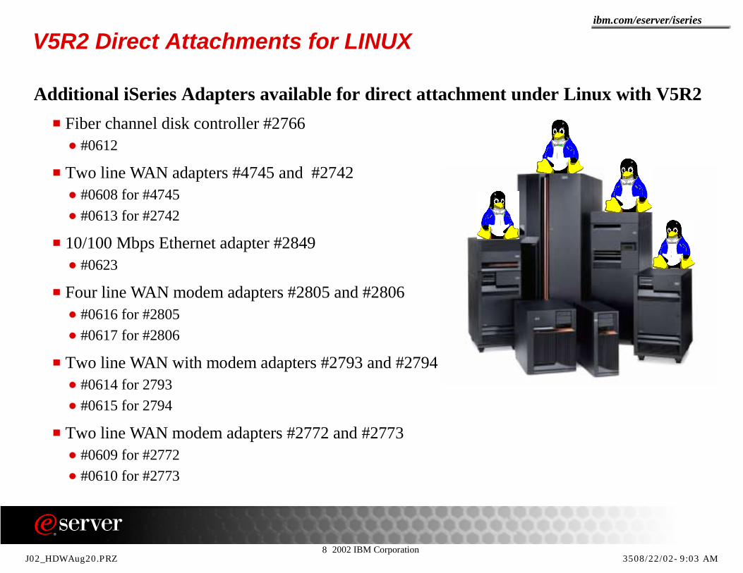
V5R2 Direct Attachments for LINUX
Additional iSeries Adapters available for direct attachment under Linux with V5R2Fiber channel disk controller #2766
#0612
Two line WAN adapters #4745 and #2742#0608 for #4745#0613 for #2742
10/100 Mbps Ethernet adapter #2849#0623
Four line WAN modem adapters #2805 and #2806#0616 for #2805#0617 for #2806
Two line WAN with modem adapters #2793 and #2794#0614 for 2793#0615 for 2794
Two line WAN modem adapters #2772 and #2773#0609 for #2772#0610 for #2773
J02_HDWAug20.PRZ 3508/22/02-9:03 AM

8 2002 IBM Corporation
ibm.com/eserver/iseries
Notes: V5R2 Direct Attachments for LINUXA number of new direct attachment features for Linux are available with V5R2. Cards being controlled by the Linux operating system do not use/require PCI IOPs. Linux direct attach PCI cards are supported only in a secondary LPAR partition. The existing direct attachments for Linux with V5R1 were limited to features #0607, #0601 and #0602 100/10Mbps Ethernet and 1Gb Ethernet adapters, #0603 100/10Mbps Token Ring adapter and the #0604, #0605 and #0606 Disk adapters. The addition of the direct attachment features mentioned in this foil largely extend the possibilities to directly address a much wider set of device attachments directly from the Linux environment on the iSeries server.
J02_HDWAug20.PRZ 3608/22/02-9:03 AM
8 2002 IBM Corporation
ibm.com/eserver/iseries
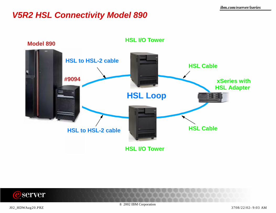
V5R2 HSL Connectivity Model 890
HSL Loop
HSL Cable
xSeries with HSL Adapter
HSL I/O Tower
HSL I/O Tower
HSL CableHSL to HSL-2 cable
Model 890
HSL to HSL-2 cable
#9094
J02_HDWAug20.PRZ 3708/22/02-9:03 AM
8 2002 IBM Corporation
ibm.com/eserver/iseries
Notes: V5R2 HSL ConnectivityOn the Model 890 only HSL towers are supported, No other towers are allowed. There are special cables available for running the HSL connections from the Model 890 to the HSL expansion towers. The base I/O tower #9094 is connected to the model 890 with HSL-2 cables.Cables can be easily identified when looking at the connectors. HSL-2 connectors on any HSL cable are colored black. HSL connectors on any HSL cable are colored yellow. All other 8XX Models and the Model 270 use HSL cables with yellow connectors only. Optical HSL cables are common for all optical HSL connections between optical HSL adapters. The following is a summary of the available HSL cables:
#1460 3m HSL Cable #1461 6m HSL Cable #1462 15m HSL Cable #1483 10m HSL-2 Cable (Model 890 only) #1485 15m HSL-2 Cable (Model 890 only) #1470 6m HSL Optical Cable #1471 30m HSL Optical Cable #1472 100m HSL Optical Cable #1473 250m HSL Optical Cable #1474 6m HSL to HSL-2 Cable (Model 890 only) #1475 10m HSL to HSL-2 Cable (Model 890 only)
Additional HSL considerations:Reliability : The HSL loop architecture provides redundant paths between any two nodes on the loop. An optimum path is set up when configured at IPL time and the alternative direction around the loop is used if a failure prevents communication in the preferred direction. When there are IXS towers in a loop be aware of the fact that the xSeries server must be varied off from the iSeries before powering down that server. Powering down a HSL attached xSeries server without a vary off first will break the HSL loop.Number / type of cables and performance : To minimize the number of cables, the system can be configured by attaching the maximum number of I/O towers to an HSL Loop before using another HSL loop, but, to maximize performance, the system can be configured by spreading out the I/O towers across the greatest number of HSL loops possible. When configuring optical HSL cables, remember that the total loop speed is only 500MB per second instead of 1GB per second.
J02_HDWAug20.PRZ 3808/22/02-9:03 AM

8 2002 IBM Corporation
ibm.com/eserver/iseries
HSL Cluster Connectivity
Up to three CEC nodes in a HSL loop
No external Towers allowed in this loop
Single loop servers limited to two CEC nodes
Model 890Up to 14 loops
Copper and optical
Maximum six I/O towers per loop
Up to four switchable towers per loopMaximum three per segment
Total maximum of nine towers per loopIncluding IXS with IXA
J02_HDWAug20.PRZ 3908/22/02-9:03 AM

8 2002 IBM Corporation
ibm.com/eserver/iseries
Notes: HSL Cluster ConnectivityConnecting up to three iSeries servers together using a single HSL loops when they have cluster enabled HSL adapters can be accomplished in V5R2 when there are no other HSL nodes on that same loop (this includes internal nodes). Any I/O node in the HSL loop will restrict the number of CEC nodes in that same loop to two. Since the model 270 and the model 820 both have a CEC HSL node and a internal I/O node on their single HSL loop, they can only participate in a HLS cluster loop with maximum two server CEC nodes. The models 830 /840 and 890 however all have the capability to use one or more ports of their cluster enabled adapters exclusively for attaching CEC HSL nodes only. Switchable towers can be connected between cluster nodes in an other HSL loop. But that HLS loop can by definition only contain two CEC nodes. There are many HSL configurations possible, especially with models that have multiple HSL loops. However, there are a number of rules that have to be respected and even then, many functionally supported configurations may not provide optimal or even acceptable performance for a given application. One of the first rules to consider is the maximum allowable external towers (base) for an HSL loop in a single system configuration. The other rules are a little more complicated. When switchable towers are involved, other rules apply , such as the maximum of four switchable towers per loop with two HSL CEC nodes and at the same time there can be maximum three switchable towers per HSL segment. The setup guide for HSL attached towers, SA41-5149-xx contains the necessary information regarding HSL cabling rules.Note: Refer to the Appendix to this presentation for HSL adapter specifications.
J02_HDWAug20.PRZ 4008/22/02-9:03 AM
8 2002 IBM Corporation
ibm.com/eserver/iseries
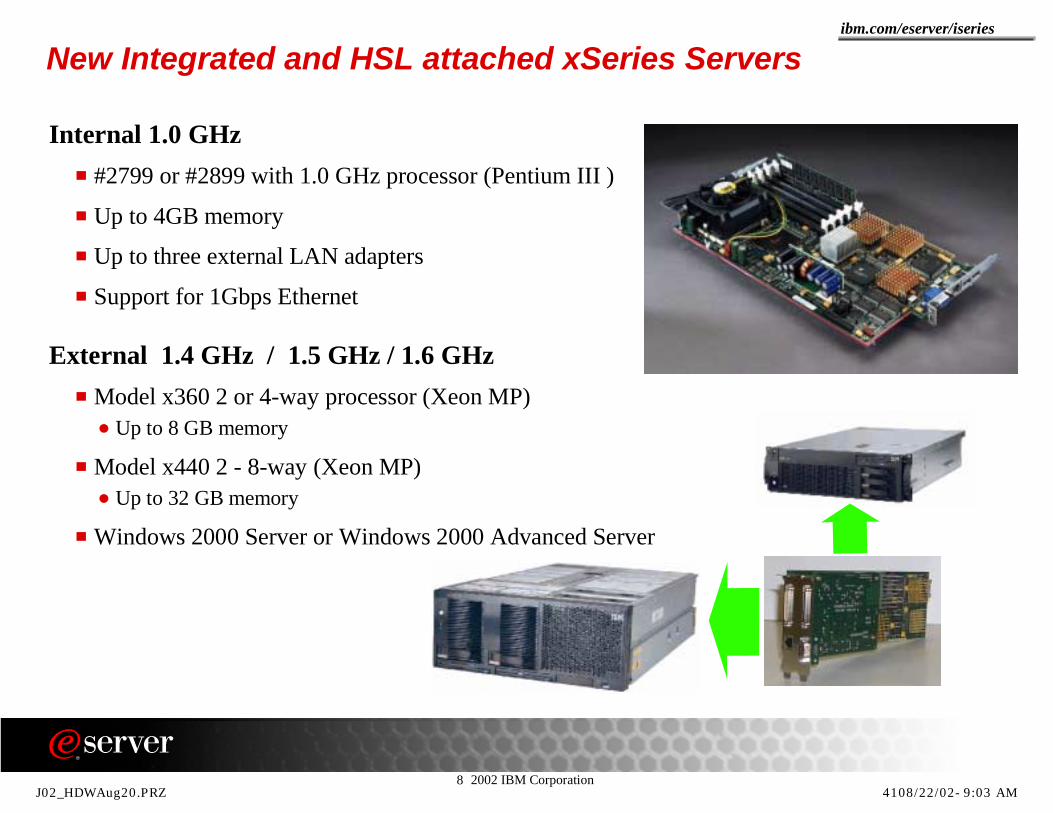
New Integrated and HSL attached xSeries Servers
Internal 1.0 GHz#2799 or #2899 with 1.0 GHz processor (Pentium III )
Up to 4GB memory
Up to three external LAN adapters
Support for 1Gbps Ethernet
External 1.4 GHz / 1.5 GHz / 1.6 GHzModel x360 2 or 4-way processor (Xeon MP)
Up to 8 GB memory
Model x440 2 - 8-way (Xeon MP) Up to 32 GB memory
Windows 2000 Server or Windows 2000 Advanced Server
J02_HDWAug20.PRZ 4108/22/02-9:03 AM

8 2002 IBM Corporation
ibm.com/eserver/iseries
Notes : Integrated xSeries Server
iSeries Model # of IXS270 3820 12830 28840 32890 32
iSeries Model # of IXA270 2820 4830 8840 16890 32
The new earlier announced Integrated xSeries Server #2799 / #2899 (#2899 is the Model 270 version) contains a 1.0 GHz Pentium III processor and 4 memory slots. Each slot can contain either a 128, a 256 or 1024 MB memory card. When the maximum memory (4GB) is installed, only 3712 MB is addressable. One LAN card must be installed. The LAN adapters supported by the #2799 Integrated xSeries Server are the #2744 (100/10Mbps Token Ring), the #4838 (100/10Mbps Ethernet adapter), the #2743 (1Gbps optical Ethernet) and the #2760 (10Mbps/100Mbps/1Gbps UTP Ethernet).Available memory features:
#2795 128 MB IXS memory feature#2796 256 MB IXS memory feature#2797 1024 MB IXS memory feature
See the table for maximum integrated xSeries Servers per iSeries Model.
The x360 is the industry’s first 2 / 4-way server in a 3U (three EIA standard rack unit) package. It features the new Intel Xeon Processor MP, starting at 1.4GHz. The x360 supports up to 8GB of Chipkill memory.The x440, is the industry’s first 4 / 8-way capable server to fit in a 4U (four EIA standard rack unit) package. This scalable Enterprise X-Architecture server supports either one or two SMP Expansion Modules per chassis. Each module holds 4 Xeon Processor MP chips, 16GB of memory (with Chipkill capabilities and memory mirroring support) for a maximum total of 32 MB for the 8-way processor. Both new integrated xSeries servers can have processors running at 1.4 GHz, at 1.5 GHz or at 1.6 GHz. The HSL adapter must be installed for use with the iSeries Server and Windows 2000 Server or Windows 2000 Advanced Server is required.See table for maximum integrated xSeries Servers per iSeries Model.
Note: Supported HSL attached xSeries serversxSeries Models : x250, x350, x235, x255, x360 and x440Netfinity Models : 7100 or 7600
See the next foil for a website listing the external xSeries supported on iSeries.
J02_HDWAug20.PRZ 4208/22/02-9:03 AM

8 2002 IBM Corporation
ibm.com/eserver/iseries
Integrated xSeries Server - supported model referencehttp://www-1.ibm.com/servers/eserver/iseries/windowsintegration/
J02_HDWAug20.PRZ 4308/22/02-9:03 AM

8 2002 IBM Corporation
ibm.com/eserver/iseries
Notes: Integrated xSeries Server - supported models
This foil shows the first page of the Integrated xSeries servers that are supported on iSeries via the Integrated xSeries Adapter.
Use the URL shown on the foil and from the left navigation bar, and select Support for Selected x235 and x255 Models
As you can see this web site lists more than just the x235 and x255 models. There are additional "support notes" for the varies xSeries models.
Here is an excerpt from the notes portion at this website.
Note 1: With the Integrated xSeries Adapter configuration, all the disk drives for the xSeries server are under the control of the iSeries server. There is no disk in the xSeries server. When ordering xSeries servers, do not order internal or external xSeries controlled disk or disk controller adapters. Any disk drives and disk controller adapters that may be installed in the xSeries server need to be removed before the IXA installation process is started.
Note 2: IXA requires interconnect cables for xSeries x360 and x440. To connect the Integrated xSeries Adapter to the xSeries service processor on the x360 and x440, interconnect cables are required. The interconnect cables provide the conversion from the RJ45 cable provided with the IXAto the RJ14 connector on the xSeries service processor. The Interconnect Cables required are included in the xSeries Advanced Systems Management Interconnect Cable Kit, Part Number 03K9309. This part is required for each x360 and x440 server that will attach to the iSeries via the IXA. or more information on the interconnect cables please refer to the xSeries Configuration and Options Guide at: ftp://ftp.pc.ibm.com/pub/pccbbs/pc_servers_pdf/uscog.pdf Appendix G, Systems Management Overview, page 202. These interconnect cables are included with new orders of the IXA (1519-100) starting July 1, 2002.
Note 3: The IXA does not support xSeries servers with more than 8 processors. The IXA does not support Microsoft Windows 2000 Server Datacenter Edition.
Note 4: The following PTFs are required to allow the iSeries to power down and reboot x360, x440, x255 and x235 servers: MF27536 and MF27927. These PTFs are included in cumulative PTF package C2134510.
Note 5: The x360 models require a firmware update. Please contact Sam Gutierrez at [email protected] for further information.
J02_HDWAug20.PRZ 4408/22/02-9:03 AM

8 2002 IBM Corporation
ibm.com/eserver/iseries
Switched Fabric and 2 Gbps Fibre Channel support
2 Gbps support for Fibre Channel adaptersFor #2765 (tape) and #2766 (disk) adapters
Code upgrade with Version 5 Release 2
All elements in the network must be 2 Gbps enabled
Cascaded switches Recommendation is maximum 3 interswitched links10 KM distance between switched
V5R2 Topology SupportPoint to Point
Arbitrated Loop / QuickLoop
Switched Fabric support
Multiple target support with Switched Fabric)#2765 up to 16 targets
#2766 up to 32 targets (Maximum 32 LUNs)
Switches :2109 S08 / S16 , F16 (1Gbps)2109 F16 (2Gbps)
Hub :3534 1RU (1Gbps)
Newer, faster, more flexible technology supported by V5R2
J02_HDWAug20.PRZ 4508/22/02-9:03 AM

8 2002 IBM Corporation
ibm.com/eserver/iseries
Notes: Switched Fabric and 2 Gbps Fibre Channel supportVersion 5 Release 2 code now includes support for multiple targets from a single Fibre Channel (FC) tape or Fibre Channel (FC) disk adapter. Previously at Version 5 Release 1 only a single target was supported from an single initiator (FC adapter). The existing adapters, feature #2765 for tape and feature #2766 for DASD are fully enabled for 2Gbps. No additional hardware is required, simply loading the V5R2 code is sufficient to enable 2Gbps support. The adapters are auto-sensing and will run at either 1Gbps or 2Gbps. To gain full benefit of this change all elements in the SAN infrastructure need to be enabled for 2Gbps. The 3583 tape library and the recently announced IBM TotalStorage Enterprise Storage Server (ESS, code named "Shark") Model 800 and 800 Turbo options support 2-Gigabit-per-second Fibre/FICON data transfer rates.
Announcements are expected later in the year for the 3584 and 3590 tape configurations.
Achieving any of the possible maximum throughput rates, of course, is dependent on the number of active devices (exchanging data) using the same iSeries #2765/#2766 HSL adapter, the actual switched fabric network configuration, and the iSeries CPU processor capacity (CPW) available to the active application. When able to drive attached devices at their maximum rated speeds, it is recommended to limit the number of devices attached to the same #2765/#2766 HSL adapter to 3.
The 10KM distance supported distance between the switches remains unchanged with V5R2 support for 2Gbps. In addition more than two cascaded switches between the initiator and the target are supported. This allows the iSeries to fully participate in more complex SAN fabrics and enables the user to extend the distance between the initiator and target. Performance issues must be considered when extending the distance between initiator and target. And then there will be always limitations for the simple reason that light in optical fiber can only travel 200 Km per millisecond and in a switch there is an average port to port latency of two milliseconds.
With the multi target support in the code of Version 5 Release 2, a single adapter can address multiple targets. This means a substantial reduction of the required FC adapters needed for connecting multiple tape or DASD storage servers to the iSeries Server. The number of LUNs that can be addressed from a unique adapter must be respected. Fact is that there are other considerations such as the bandwidth limitations that may have an impact on performance when they are not taken into account. A simple example: depending on the data structure, 3 or 4 high speed optical attached tape unit datastreams can easily saturated the full FC adapter capability.
A #2765 can address up to 16 targets; however, note that a single tape library with a single drive in it consists of two targets and each additional drive in the library is also an additional target. The capability of the #2766 on the other hand allows you to address up to 32 ESS servers. Note, however, since there is a limit of 32 LUNs also, it would mean that if the maximum number of ESS servers is configured, each server can only contain one single LUN which is not a very workable configuration. Users should use common sense when configuring multiple targets on any FC adapter.IBM switches that support 2Gbps are the 2109 Model F16 and the 3534 Model F08. The 3534 F08 is not listed on this chart because testing with iSeries was scheduled to be done after this presentation was created.
J02_HDWAug20.PRZ 4608/22/02-9:03 AM

8 2002 IBM Corporation
ibm.com/eserver/iseries
Notes: Switched Fabric and 2 Gbps Fibre Channel support -2The switches and hubs 2109-S08/S16, 2109-F16, 3534 1RU can be configured according to the required V5R1 iSeries arbitrated loop/QuickLloop protocols.
In V5R2 you can still run the point to point, QuickLoop configuration, but the V5R2 switched fabric support is recommended.
For use on the iSeries, the QuickLoop feature of the switch device provides the firmware that enables devices connected to ports of the switch to be handled as private loop devices. QuickLoop creates a unique fibre channel topology that allows host bus adapters (such as the #2765 and #2766) that use fibre channel arbitrated loop (FC-AL) without knowledge of SAN fabric, commonly to communicate with fibre channel arbitrated loop storage devices through IBM 2109 Fibre Channel Switches. QuickLoop allows individual switch ports to be designated as arbitrated loop ports, allowing a private host initiator to communicate with arbitrated loop storage devices as though they were all contained in one logical loop. These QuickLoop switch ports can be located on one switch, or on two switches either directly connected to each other or connected within a SAN fabric. A SAN fabric can contain many independent Quickloops but only one or two switches can be designated to build a single logical arbitrated loop in which private loop initiators can communicate.
The QuickLoop devices have been successfully tested so that even with V5R1 OS/400, they can share Shark fibre cards, even at V5R1. This is done using "translative mode" that lets a fabric host port talk to an FC-AL device port. Although the Shark port is designated as FC-AL in this configuration, the fabric hosts are unaware that the Shark is running in FC-AL.
In V5R2 use the arbitrated loop/QuickLoop configuration only where the customer environment requires its. For new V5R2 configurations using the SAN switched fabric configuration, supported by the 2109 F16 switch is recommended.
Mixed V5R1/V5R2 configurations: The V5R1 configurations continue to require both the host and target switch ports to be in QuickLoop mode.If possible, the V5R2 configurations should be logically (if not physically) separated from V5R1 zones. Again, the V5R2 zones would be fabric and the V5R1 QuickLoop. If necessary (e.g. insufficient ports available on the ESS), the shared ESS configuration described below can be utilized.(V5R2 can participate in a pure QuickLoop environment as well)
The 2109 Model F16 provides full duplex operation at 2 gigabits per second port-to-port throughput with auto-sensing capability for connecting to existing 1 gigabit per second host server, storage or switch ports. The F16 is a non-blocking architecture providing multiple simultaneous connections, each capable of up to 2 gigabits per second, with a maximum latency of 2 microseconds. The Model F16 supports cascading and the capability to connect to existing 2109 switches. This switch has support for the new Small Form-Factor Pluggable (SFP) media with options for either short-waveoptical connections for distances up to 300 meters, or long-wave optical connections for distances up to 10 kilometers.
J02_HDWAug20.PRZ 4708/22/02-9:03 AM

8 2002 IBM Corporation
ibm.com/eserver/iseries
Notes: Switched Fabric and 2 Gbps Fibre Channel support -3At the time this presentation was created there was no support for an iSeries and a model of the 3534 supporting the switched fabric attachment.
Update on ESS Copy Services AS/400 models via the #6501 controller or the iSeries #2766 PCI Fibre Channel DASD Controller support attachment of Enterprise Storage Server models as discussed. There are two well-known ESS disk "copy/backup" procedures that are formally supported for iSeries attached ESS disks. These are listed below. This support is under Storage Division announcements and support documentation.
FlashCopy: FlashCopy provides an option for minimizing the downtime needed for data backup in an ESS environment. Providing an instantaneous or "point-in-time" copy capability, FlashCopy enables disk mirroring within a single ESS unit. iSeries support became available 4Q 2001.Peer to Peer Remote Copy: PPRC provides an ESS-based methodology to do disk mirroring to a second, remote site. This strategy can be used for iSeries disk level disaster tolerance in an ESS environment.
There are considerations when using these two "copy methods" in any environment. The most complete description of this support for iSeries is included in an ITSO "redpaper" - An Update of ESS (Shark) Features Supported by the IBM eServer iSeries Server, REDP0199, dated April 2002 and redbook IBM eServer iSeries in a Storage Architecture Network: A Guide to Implementing FC Disk and Tape with iSeries Server, SG24-6220. This information can be found at:
http://www.ibm.com/redbooksSearch for iSeries AND Storage Area
J02_HDWAug20.PRZ 4808/22/02-9:03 AM

8 2002 IBM Corporation
ibm.com/eserver/iseries
V5R2 Virtual Local Area Network
External ports with IP addressiSERIES LAN ADAPTERS
PCI BUS
NETWORK
NETWORK
xSERIES LAN ADAPTERSExternal ports with IP address
P0 OS/400
P1OS/400 orLINUX
P2OS/400 IXSIXS
IXAIXA IXA
HSLPRIVATE LANPARTITION NETWORKVIRTUAL ETHERNET
J02_HDWAug20.PRZ 4908/22/02-9:03 AM

8 2002 IBM Corporation
ibm.com/eserver/iseries
Notes: V5R2 Virtual Local Area Network This foil shows the various LAN attachments between partitions and IXS. An IXS, or HSL-attached xSeries server can communicates with OS/400 through a point-to-point private LAN with only two endpoints, Windows and OS/400. Virtual Ethernet emulates 1 Gbps support but does not use external network adapters or cables. All data sent over this virtual LAN is secure because it never leaves the iSeries server. Virtual Ethernet connections for are only supported with Windows 2000 Server or Windows 2000 Advanced Server configured on hardware resource types (CCIN) 2890 and (CCIN) 2689. When the user runs the INSWNTSVR command, the correct type of LAN will be created based on the criteria for each type.
When the environment of a Windows server using internal LAN is updated, and it meets all of the requirements for the point-to-point Virtual Ethernet, the internal LAN will be automatically updated to the Virtual Ethernet. The private LAN uses restricted Internet addresses in private domains, so the addresses are not propagated through gateways or routers. These addresses take the form of 192.168.xxx.yyy, where xxx is the hardware resource ending number (the xxx and yyy can be from 1 to 3 digits.) For example, for an Integrated xSeries Server that is defined for LIN03, xxx=3, the address is 192.168.3.yyy. As the user defines multiple network descriptions for the same hardware resource, yyy is incremented. The user can allow the INSWNTSVR command to automatically assign these Internet addresses or specify addresses to prevent TCP/IP address collisions with other hosts on the system.
Virtual Ethernet on the iSeries is very flexible and can be configured for a variety of applications, such as a single network that connects a group of Windows servers on the same iSeries system, or multiple networks on the same iSeries system that connects only selected Windows servers while maintaining isolation from others and even for inter-LPAR networks, meaning for servers with the logical partition implemented, the virtual LAN can be used to connect selected partitions that may be running Linux, OS/400, or Windows servers running under different OS/400 partitions. For this last mentioned type of configuration, the user needs to enable a LPAR virtual LAN connection as described in Logical partition concepts. Windows servers are limited to using Virtual LAN port numbers 0 through 9. These port numbers correspond to Port Number values *VRTETH0 through *VRTETH9 in the Ethernet line descriptions. For a Windows server to communicate with another OS/400 partition, you need to create a line description within the owning partition to access the Virtual Ethernet being used. You must then configure a TCP/IP address for that line. Windows servers running under different OS/400 partitions using the same Virtual Ethernet port number values will be isolated if no inter-LPAR connection is enabled between the OS/400 partitions using that same Virtual LAN port number.
More detailed information regarding virtual Ethernet and how to configure the different types of connections can be found on the iSeries InfoCenter.Here is how to find the information easily: open the following tabs
Integrated Operating environmentsWindows server on iSeries
Install and configure iSeries Integration for Windows ServerPre-installation checklist for iSeries Integration for Windows Server
from there explore the Local area networks used by Windows server on iSeries.
J02_HDWAug20.PRZ 5008/22/02-9:03 AM
8 2002 IBM Corporation
ibm.com/eserver/iseries
V5R2 Hardware Upgrades and Migration
J02_HDWAug20.PRZ 5108/22/02-9:03 AM

8 2002 IBM Corporation
ibm.com/eserver/iseries
V5R2 Hardware Model to Model Upgrade Overview
Model 730
Model 740
Model 830
Model 840
Model 890
Model 720
Model 820
J02_HDWAug20.PRZ 5208/22/02-9:03 AM

8 2002 IBM Corporation
ibm.com/eserver/iseries
Notes: Hardware Upgrades to Model 890With V5R2 there are a number of new upgrade paths available as already discussed in the previous chapter. All these different upgrade paths can be found in the System Builder redbook and are supported by the e-Config configurator tool. Single step upgrades to the Model 890 are only supported from the Model 740, the Model 830 and the Model 840. The other processor features such as these of the Models 720,730 and 820 can upgrade to the Model 830 or the Model 840 depending on what processor feature conversions are available.You have to remember that there is no SPD support on the Model 890 when planning for the upgrade in this model. In the next foils we will discuss some other important upgrade planning considerations. The valid upgrade path details can be found in the sales guide and the V5R2 System Builder. Using the iSeries configurator tool is the safest way to identify a valid upgrade path for your existing configuration.
J02_HDWAug20.PRZ 5308/22/02-9:03 AM
8 2002 IBM Corporation
ibm.com/eserver/iseries
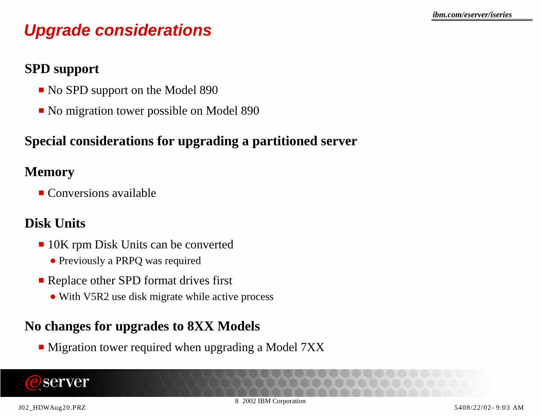
Upgrade considerations
SPD supportNo SPD support on the Model 890
No migration tower possible on Model 890
Special considerations for upgrading a partitioned server
MemoryConversions available
Disk Units10K rpm Disk Units can be converted
Previously a PRPQ was required
Replace other SPD format drives firstWith V5R2 use disk migrate while active process
No changes for upgrades to 8XX ModelsMigration tower required when upgrading a Model 7XX
J02_HDWAug20.PRZ 5408/22/02-9:03 AM
8 2002 IBM Corporation
ibm.com/eserver/iseries
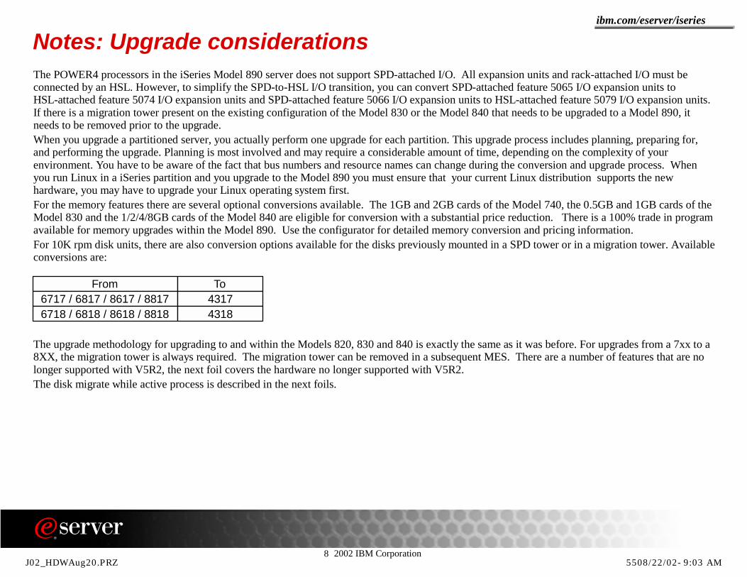
Notes: Upgrade considerationsThe POWER4 processors in the iSeries Model 890 server does not support SPD-attached I/O. All expansion units and rack-attached I/O must be connected by an HSL. However, to simplify the SPD-to-HSL I/O transition, you can convert SPD-attached feature 5065 I/O expansion units to HSL-attached feature 5074 I/O expansion units and SPD-attached feature 5066 I/O expansion units to HSL-attached feature 5079 I/O expansion units. If there is a migration tower present on the existing configuration of the Model 830 or the Model 840 that needs to be upgraded to a Model 890, it needs to be removed prior to the upgrade.When you upgrade a partitioned server, you actually perform one upgrade for each partition. This upgrade process includes planning, preparing for, and performing the upgrade. Planning is most involved and may require a considerable amount of time, depending on the complexity of your environment. You have to be aware of the fact that bus numbers and resource names can change during the conversion and upgrade process. When you run Linux in a iSeries partition and you upgrade to the Model 890 you must ensure that your current Linux distribution supports the new hardware, you may have to upgrade your Linux operating system first.For the memory features there are several optional conversions available. The 1GB and 2GB cards of the Model 740, the 0.5GB and 1GB cards of the Model 830 and the 1/2/4/8GB cards of the Model 840 are eligible for conversion with a substantial price reduction. There is a 100% trade in program available for memory upgrades within the Model 890. Use the configurator for detailed memory conversion and pricing information.For 10K rpm disk units, there are also conversion options available for the disks previously mounted in a SPD tower or in a migration tower. Available conversions are:
The upgrade methodology for upgrading to and within the Models 820, 830 and 840 is exactly the same as it was before. For upgrades from a 7xx to a 8XX, the migration tower is always required. The migration tower can be removed in a subsequent MES. There are a number of features that are no longer supported with V5R2, the next foil covers the hardware no longer supported with V5R2.The disk migrate while active process is described in the next foils.
From To6717 / 6817 / 8617 / 8817 43176718 / 6818 / 8618 / 8818 4318
J02_HDWAug20.PRZ 5508/22/02-9:03 AM
8 2002 IBM Corporation
ibm.com/eserver/iseries
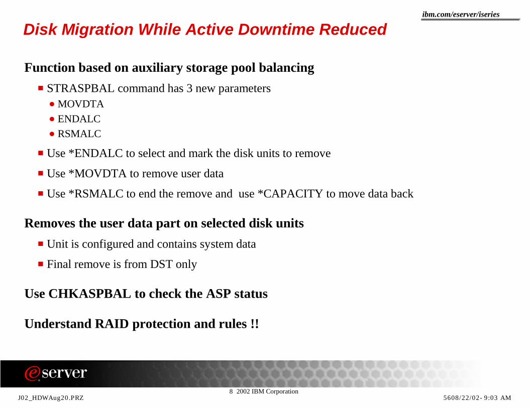
Disk Migration While Active Downtime Reduced
Function based on auxiliary storage pool balancingSTRASPBAL command has 3 new parameters
MOVDTAENDALCRSMALC
Use *ENDALC to select and mark the disk units to remove
Use *MOVDTA to remove user data
Use *RSMALC to end the remove and use *CAPACITY to move data back
Removes the user data part on selected disk unitsUnit is configured and contains system data
Final remove is from DST only
Use CHKASPBAL to check the ASP status
Understand RAID protection and rules !!
J02_HDWAug20.PRZ 5608/22/02-9:03 AM

8 2002 IBM Corporation
ibm.com/eserver/iseries
Unit Identification for Disk Migration While Active
J02_HDWAug20.PRZ 5708/22/02-9:03 AM
8 2002 IBM Corporation
ibm.com/eserver/iseries
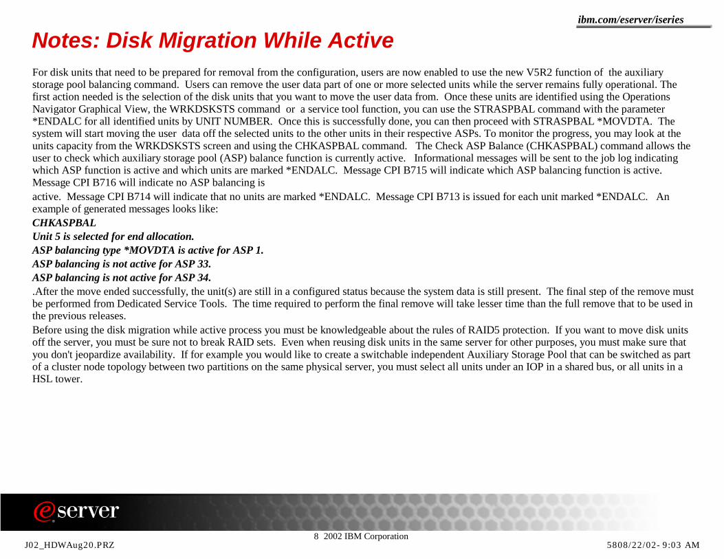
Notes: Disk Migration While ActiveFor disk units that need to be prepared for removal from the configuration, users are now enabled to use the new V5R2 function of the auxiliary storage pool balancing command. Users can remove the user data part of one or more selected units while the server remains fully operational. The first action needed is the selection of the disk units that you want to move the user data from. Once these units are identified using the Operations Navigator Graphical View, the WRKDSKSTS command or a service tool function, you can use the STRASPBAL command with the parameter *ENDALC for all identified units by UNIT NUMBER. Once this is successfully done, you can then proceed with STRASPBAL *MOVDTA. The system will start moving the user data off the selected units to the other units in their respective ASPs. To monitor the progress, you may look at the units capacity from the WRKDSKSTS screen and using the CHKASPBAL command. The Check ASP Balance (CHKASPBAL) command allows the user to check which auxiliary storage pool (ASP) balance function is currently active. Informational messages will be sent to the job log indicating which ASP function is active and which units are marked *ENDALC. Message CPI B715 will indicate which ASP balancing function is active. Message CPI B716 will indicate no ASP balancing is active. Message CPI B714 will indicate that no units are marked *ENDALC. Message CPI B713 is issued for each unit marked *ENDALC. An example of generated messages looks like:CHKASPBALUnit 5 is selected for end allocation.ASP balancing type *MOVDTA is active for ASP 1.ASP balancing is not active for ASP 33.ASP balancing is not active for ASP 34..After the move ended successfully, the unit(s) are still in a configured status because the system data is still present. The final step of the remove must be performed from Dedicated Service Tools. The time required to perform the final remove will take lesser time than the full remove that to be used in the previous releases.Before using the disk migration while active process you must be knowledgeable about the rules of RAID5 protection. If you want to move disk units off the server, you must be sure not to break RAID sets. Even when reusing disk units in the same server for other purposes, you must make sure that you don't jeopardize availability. If for example you would like to create a switchable independent Auxiliary Storage Pool that can be switched as part of a cluster node topology between two partitions on the same physical server, you must select all units under an IOP in a shared bus, or all units in a HSL tower.
J02_HDWAug20.PRZ 5808/22/02-9:03 AM

8 2002 IBM Corporation
ibm.com/eserver/iseries
Hardware not Supported with V5R2
AS/400 ModelsModel 4xx and Model 5xx do not support V5R2
Other Hardware13GB QIC Tape drives
Diskette Drives
Hardware not supported on the Model 890SPD and SPD attached PCI (migration towers and 506x)
Read Cache Device
Internal QIC Tape drives 1.2GB / 2.5GB and 13GB
ISDN Adapters
OS/400 V5R2 is the last release to supportAS/400 Models 150, 600, 620, 640, 650, S10, S20, S30, S40 and SB1
ATM Adapters
J02_HDWAug20.PRZ 5908/22/02-9:03 AM
8 2002 IBM Corporation
ibm.com/eserver/iseries
Notes: Hardware not Supported with V5R2As previously announced, the Models 4xx and Models 5xx are no longer supported with V5R2. Since there was no longer a requirement for the use of diskette media on the iSeries the support for diskette drives is withdrawn as from V5R2 onwards. The 13GB internal quarter inch tape drives are no longer supported with the V5R2 OS/400 release.On the Model 890, there is no longer support for SPD type busses. This means that you can not connect migration towers such as the #5033, #5034, #5035 and the #5077 to any of the available HSL loops on the Model 890. Of course this also means that there is no way to connect a tower that can provide SPD cards nor can a tower with SPD bus based PCI cards such as for example the #5065 or #5066 be attached either. There is no support provided for the following internal quarter inch tape devices: all QIC-1000, all QIC-2GB and all 13GB QIC-5010 drives. The Model 890 will not support the internal read cache device #4331. There is also no support for ISDN adapters on the Model 890. The #4750 and #4751 ISDN adapters are still supported on the 270, 820, 830 and the 840 models.V5R2 is the final release that will offer support for the AS/400 Models 150, 600, 620, 640, 650, S10, S20, S30, S40 and SB1. The V5R2 subsequent release will also offer no support for ATM adapters.
J02_HDWAug20.PRZ 6008/22/02-9:03 AM

8 2002 IBM Corporation
ibm.com/eserver/iseries
Upgrade Model 830 or Model 840 to Model 890
V5R2 Required !
#5066 #5079
#5079
HSL
SPD
#5079
#5079
HSL
!HSL
#5077
J02_HDWAug20.PRZ 6108/22/02-9:03 AM
8 2002 IBM Corporation
ibm.com/eserver/iseries
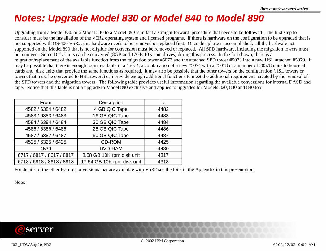
Notes: Upgrade Model 830 or Model 840 to Model 890Upgrading from a Model 830 or a Model 840 to a Model 890 is in fact a straight forward procedure that needs to be followed. The first step to consider must be the installation of the V5R2 operating system and licensed programs. If there is hardware on the configuration to be upgraded that is not supported with OS/400 V5R2, this hardware needs to be removed or replaced first. Once this phase is accomplished, all the hardware not supported on the Model 890 that is not eligible for conversion must be removed or replaced. All SPD hardware, including the migration towers must be removed. Some Disk Units can be converted (8GB and 17GB 10K rpm drives) during this process. In the foil shown, there is a migration/replacement of the available function from the migration tower #5077 and the attached SPD tower #5073 into a new HSL attached #5079. It may be possible that there is enough room available in a #5074, a combination of a new #5074 with a #5078 or a number of #0578 units to house all cards and disk units that provide the same functions as required. It may also be possible that the other towers on the configuration (HSL towers or towers that must be converted to HSL towers) can provide enough additional functions to meet the additional requirements created by the removal of the SPD towers and the migration towers. The following table provides useful information regarding the available conversions for internal DASD and tape. Notice that this table is not a upgrade to Model 890 exclusive and applies to upgrades for Models 820, 830 and 840 too.
For details of the other feature conversions that are available with V5R2 see the foils in the Appendix in this presentation.
Note:
From Description To4582 / 6384 / 6482 4 GB QIC Tape 44824583 / 6383 / 6483 16 GB QIC Tape 44834584 / 6384 / 6484 30 GB QIC Tape 44844586 / 6386 / 6486 25 GB QIC Tape 44864587 / 6387 / 6487 50 GB QIC Tape 44874525 / 6325 / 6425 CD-ROM 4425
4530 DVD-RAM 44306717 / 6817 / 8617 / 8817 8.58 GB 10K rpm disk unit 43176718 / 6818 / 8618 / 8818 17.54 GB 10K rpm disk unit 4318
J02_HDWAug20.PRZ 6208/22/02-9:03 AM

8 2002 IBM Corporation
ibm.com/eserver/iseries
Upgrade Model 740 to Model 890#5079
#5079
V5R2 Required !
#5066
SPD
HSL#5066
#5066
SPD!!
!
#5083 / #5073
J02_HDWAug20.PRZ 6308/22/02-9:03 AM

8 2002 IBM Corporation
ibm.com/eserver/iseries
Notes: Upgrade Model 740 to Model 890Additional concerns need to be taken into account when upgrading a Model 740 to a Model 890. In the previous foils, you can see the flow of two different scenarios for accomplishing the upgrade to a Model 890.he first foil depicts the scenario where the SPD hardware is replaced with PCI hardware that is enabled for conversion into HSL connected hardware. The intention here is to make the Model 740 ready for the upgrade by removing all incompatible hardware as much as possible upfront. The advantage of this approach is that it enables testing of PCI replacements before the actual Model change. However, the disadvantage is that this type of upgrade restricts you to PCI adapters that are supported in a #5065/#5066 tower only and you must also buy #2824 IOPs that can't be reused during the next step. Thus you have to remember that V5R2 is required before completing the upgrade to the Model 890 and you must be aware of the fact that you should not configure hardware in the SPD bus PCI towers that is not supported with V5R2 such as the ISDN adapters and the #4800 cryptographic processor, simply because the next step requires the installation of the new release. The second step is the upgrade from the Model 740 to the Model 890 and the conversion of all #5065/#5066 towers to #5074/#5079 towers. The base I/O tower from the Model 740 is replaced with the new base I/O tower of the Model 890. There are special considerations for the disk units in the base I/O tower. These special considerations will be covered in the notes of the next foil where the one step upgrade approach is discussed.
J02_HDWAug20.PRZ 6408/22/02-9:03 AM

8 2002 IBM Corporation
ibm.com/eserver/iseries
Upgrade Model 740 to Model 890
#5079
#5079
V5R2 Required !
#5066
#5083 / #5073SPD
HSLSPD
!!
!Replace except....
J02_HDWAug20.PRZ 6508/22/02-9:03 AM

8 2002 IBM Corporation
ibm.com/eserver/iseries
Notes: Upgrade Model 740 to Model 890The single step approach is shown in the second foil where during the upgrade :
The SPD bus PCI tower(s) #5065/#5066 are converted to HSL bus #5074/#5079 towersThe SPD features and towers are replaced with HSL bus I/O towers or expansions depending on the need for disk placementThe CEC and base I/O tower are replacedDisk units that can be converted are convertedInternal Tape and CD-ROM/DVD-RAM devices that are eligible for conversion can be convertedFeatures that can be converted are converted. This is also true for PCI-format features in the SPD towers such as the #2838 and the ATM adapters that can reside in a SPD #2810 IOPLoad Source issue. Since the load source disk unit data needs to be brought over to the Model 890 one way or the other, a method needs to be in place to perform the upgrade and avoid a scratch install. There are two possible scenarios:
The Load Source disk unit of the Model 740 is a 10K rpm disk and can be converted to be mounted in the #9094 base I/O tower of the Model 890. In this case the CE will convert the Load Source Disk unit at the time of the upgrade. The only thing that needs to be taken care of is to make sure that all incompatible disk unit drives are logically removed from the ASPs. To accomplish this without loosing valuable time, the disk migration while active process may be used to remove the user data upfront. It is more than obvious that the ASPs where the disk units are migrated from need to have enough capacity to hold the all the data after the remove of selected units.The Load Source disk unit of the Model 740 is a disk unit that can't be converted, can't be mounted in the #9094 base I/O tower of the Model 890. In this case a new disk unit in a PCI tower must be used to pump the data of the Load Source over. Then this unit can be used to either be mounted in the base I/O tower of the Model 890, or the migrate Load Source Utility in DST can be used to move the data from the unit in the to HSL converted PCI tower to a new unit n the base I/O tower of the Model 890. The same rules as described for the previous scenario apply for the disk units that are not compatible with the Model 890 hardware.
J02_HDWAug20.PRZ 6608/22/02-9:03 AM
8 2002 IBM Corporation
ibm.com/eserver/iseries
Appendix
J02_HDWAug20.PRZ 6708/22/02-9:03 AM

8 2002 IBM Corporation
ibm.com/eserver/iseries
HSL Adapter Cards
* This card does not support Cluster functions and is no longer shipped with new 830/840 orders. The equivalent feature introduced at V5R1 can be ordered and is supported with V4R5.
Feature CCIN Name System or I/O Tower Minimum Release
9732 * 2732 HSL Ports - 8 Copper 830 proc 2400 V4R5
9733 * 2732 HSL Ports - 8 Copper 830 proc 2402, 2403 V4R5
9737 * 2737 HSL Ports - 16 Copper 840 V4R59691 2691 Base Bus Adapter 5074, 5078, 5079, 0578 V4R59739 / 2739 2739 Optical Bus Adapter 5074, 5078, 5079, 0578 V5R19777 / 2777 2754 HSL Ports - 8 Copper 830 proc 2400 V5R19752 / 2754 2754 HSL Ports - 8 Copper 830 proc 2402, 2403 V5R19774 / 2774 2758 HSL Ports - 2 Opt/6 Copper 830 proc 2400 V5R19758 / 2758 2758 HSL Ports - 2 Opt/6 Copper 830 proc 2402, 2403 V5R19755 / 2755 2755 HSL Ports - 16 Copper 840 V5R19759 / 2759 2759 HSL Ports 4 Opt/12 Copper 840 V5R12776 2776 HSL-2 Ports - 8 Copper 890 V5R22788 2788 HSL-2 Ports - 8 Optical 890 V5R29730 273B HSL-2 Ports - 2 Copper 890 V5R29887 2887 HSL-2 Bus Adapter 9094 V5R2
J02_HDWAug20.PRZ 6808/22/02-9:04 AM

8 2002 IBM Corporation
ibm.com/eserver/iseries
HSL Cables
Cable feature
Cable name 5074 5075 5078 0578
5079 8079
IXAcard
8094
Copper1460 3m HSL Copper cable X X X X X1461 6m HSL Copper cable X X X X X1462 15m HSL Copper cable X X X X X1482 4m HSL-2 cable X1483 10m HSL-2 cable X1485 15m HSL-2 cable X1474 6m HSL to HSL-2 cable X X X X X X**1475 10m HSL to HSL-2 cable X X X X X X**
Optical *1470 6m HSL Optical cable X X X X1471 30m HSL Optical cable X X X X1472 100m HSL Optical cable X X X X1473 250m HSL Optical cable X X X X
* Optical cable requires a base or feature optical HSL Port card in the tower** Used for connecting 890 CEC or 8094 to other HSL towers
J02_HDWAug20.PRZ 6908/22/02-9:04 AM
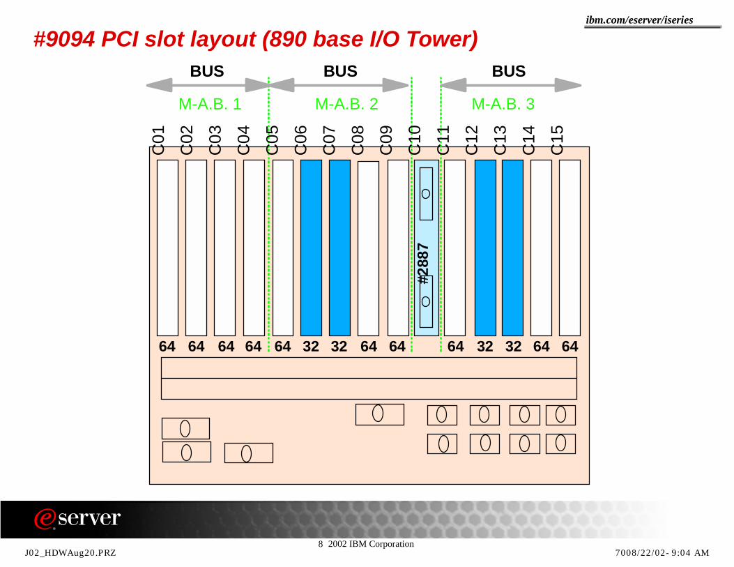
8 2002 IBM Corporation
ibm.com/eserver/iseries
#9094 PCI slot layout (890 base I/O Tower)
M-A.B. 1 M-A.B. 3M-A.B. 2
BUS BUS BUS
C01
C02
C03
C04
C05
C06
C07
C08
C09
C10
C11
C12
C13
C14
C15
#288
7
64 64 64 64 64 64 64 64 64 6432 323232
J02_HDWAug20.PRZ 7008/22/02-9:04 AM

8 2002 IBM Corporation
ibm.com/eserver/iseries
Notes: #9094 PCI slot layout This is the PCI cage layout for the 9094 (base I/O tower on 890). All other towers are exactly the same as on 840, including top unit in optional 8093, which is actually a 5074.
All slots are 3 Volt slots, numbers indicate 32 or 64 bit slots. The HSL adapter resides in slot C10.
There are now 3 system busses in this cage compared to two in the other HSL towers. Plugging rules will be documented in the System Builder - SG24-2155, update planned for later July or early July 2002.
J02_HDWAug20.PRZ 7108/22/02-9:04 AM

8 2002 IBM Corporation
ibm.com/eserver/iseries
PCI IOA Feature Support
SPD BUS HSL BUS
REPLACEOR
CONVERTShort Description
V4R5PCI SLOTSPD-BUS
V5R1PCI SLOTSPD-BUS
V5R2PCI SLOTSPD-BUS
MODEL890
#2718 #2768 R Magnetic Media Controller Y Y Y N#2720 #2742 + #4746 R WAN / Twinaxial Adapter Y Y Y N#2721 #2742 / #4745 R 2-Line WAN Adapter Y Y Y N#2722 #4746 R Twinaxial Adapter Y Y Y N#2723 #4723 C 10 Mbps Ethernet Adapter Y Y Y N#2724 #2744 R Token Ring Adapter Y Y Y N#2726 #2763 / #4778 R Disk Unit Controller Y Y Y N#2729 #2749 R Magnetic Media Controller Y Y Y N#2740 #2763 / #4778 R Disk Unit Controller Y Y Y N#2741 #4748 / #2778 R Disk Unit Controller Y Y Y N
- #2742 N/A 2-Line WAN Adapter - - - Y- #2743 N/A 1Gbps Ethernet (optical) - - - Y- #2744 N/A 10 / 100Mbps Token Ring Adapter - - - Y
#2745 #4745 C 2-Line WAN Adapter Y Y Y N#2746 #4746 C Twinaxial Adapter Y Y Y N#2748 #4748 C Disk Unit Controller Y Y Y N
- #2749 N/A Magnetic Media Controller - - - Y#2750 #4750 C ISDN U Adapter Y Y Y N#2751 #4751 C ISDN S/T Adapter Y Y Y N
- #2760 N/A 10 / 100 / 1Gbps Ethernet (UTP) - - - Y#2761 #4761 C 8-Line Integrated Modem Y Y Y N
- #2763 N/A Disk Unit Controller - - - N- #2765 N/A FC Tape Controller - - - Y- #2766 N/A FC Disk Controller - - - Y- #2768 N/A Magnetic Media Controller - - - Y
J02_HDWAug20.PRZ 7208/22/02-9:04 AM

8 2002 IBM Corporation
ibm.com/eserver/iseries
PCI IOA Feature Support SPD BUS HSL BUS
REPLACEOR
CONVERTShort Description V4R5
SPD-BUSV5R1
SPD-BUSV5R2
SPD-BUSMODEL
890- #2772 / #2773 N/A 2-Line Integrated Analog Modem - - - Y
#2778 #4778 C Disk Unit Controller Y Y Y N- #2793 / #2794 N/A 2-Line Integrated Analog Modem - - - Y- #2805 / #2806 N/A 4-Line Integrated Analog Modem - - - Y
#2811 #4815 R UTP ATM Adapter Y Y Y N#2812 - N/A Coax ATM Adapter Y Y Y N#2815 #4815 C 155 Mbps UTP OC3 ATM Y Y Y N#2816 #4816 C 155 Mbps MMF ATM Y Y Y N#2818 #4818 C 155 Mbps SMF OC3 ATM Y Y Y N#2838 #4838 C 10 / 100 Mbps Ethernet Adapter Y Y Y N
#2849 N/A 10 / 100 Mbps Ethernet Adapter - - - Y- #4723 N/A 10 Mbps Ethernet Adapter - - - Y- #4745 N/A 2-Line WAN Adapter - - - Y- #4746 N/A Twinaxial Adapter - - - Y- #4748 N/A Disk Unit Controller - - - Y- #4750 N/A ISDN U Adapter - - - N- #4751 N/A ISDN S/T Adapter - - - N- #4761 N/A 8-Line Integrated Modem - - - N- #4778 N/A Disk Unit Controller - - - Y
#4801 N/A Cryptographic Coprocessor - - - Y#4802 #4801 C Cryptographic Coprocessor Y Y Y N
- #4805 N/A Cryptographic Accelerator - - - Y- #4815 N/A 155 Mbps UTP OC3 ATM - - - Y- #4816 N/A 155 Mbps MMF ATM - - - Y- #4818 N/A 155 Mbps SMF OC3 ATM - - - Y- #4838 N/A 10 / 100 Mbps Ethernet Adapter - - - Y
J02_HDWAug20.PRZ 7308/22/02-9:04 AM
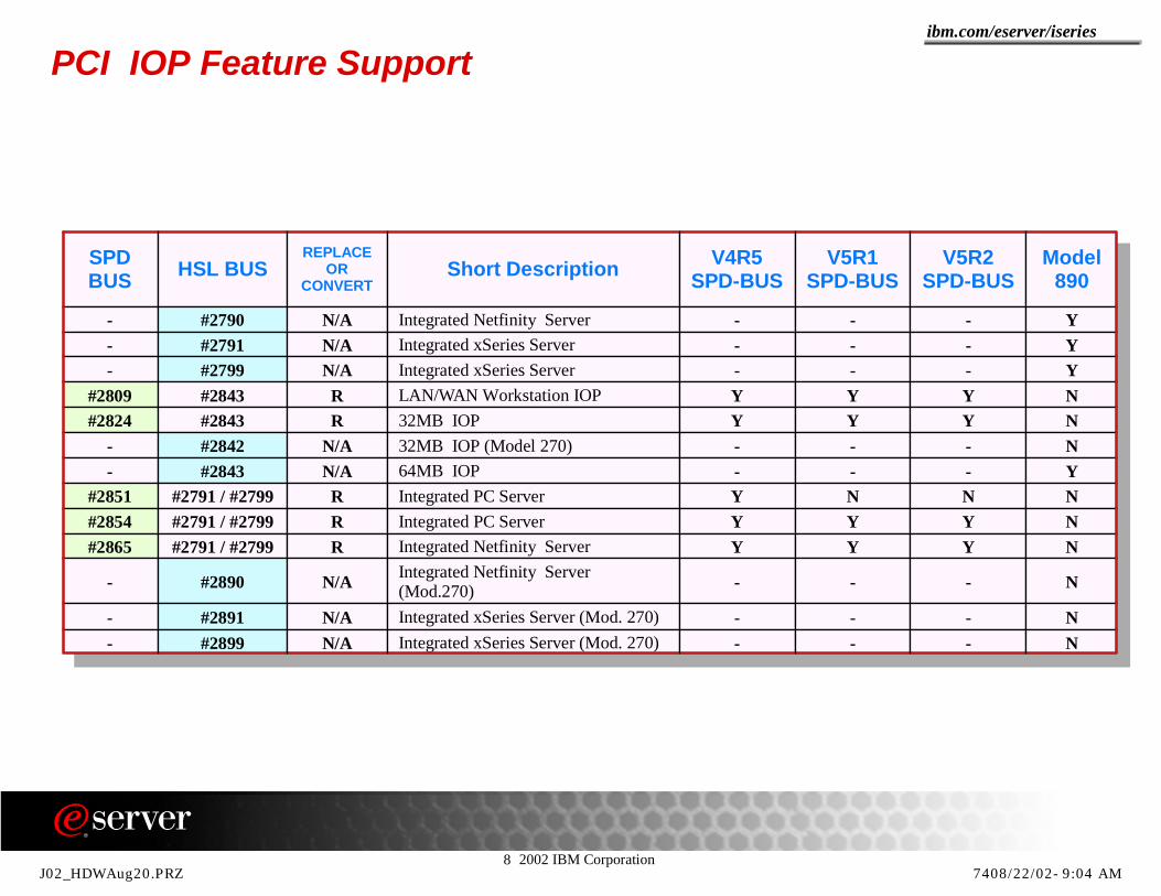
8 2002 IBM Corporation
ibm.com/eserver/iseries
PCI IOP Feature Support
SPD BUS HSL BUS
REPLACEOR
CONVERTShort Description V4R5
SPD-BUSV5R1
SPD-BUSV5R2
SPD-BUSModel
890
- #2790 N/A Integrated Netfinity Server - - - Y- #2791 N/A Integrated xSeries Server - - - Y- #2799 N/A Integrated xSeries Server - - - Y
#2809 #2843 R LAN/WAN Workstation IOP Y Y Y N#2824 #2843 R 32MB IOP Y Y Y N
- #2842 N/A 32MB IOP (Model 270) - - - N- #2843 N/A 64MB IOP - - - Y
#2851 #2791 / #2799 R Integrated PC Server Y N N N#2854 #2791 / #2799 R Integrated PC Server Y Y Y N#2865 #2791 / #2799 R Integrated Netfinity Server Y Y Y N
- #2890 N/A Integrated Netfinity Server (Mod.270) - - - N
- #2891 N/A Integrated xSeries Server (Mod. 270) - - - N- #2899 N/A Integrated xSeries Server (Mod. 270) - - - N
J02_HDWAug20.PRZ 7408/22/02-9:04 AM

8 2002 IBM Corporation
ibm.com/eserver/iseries
Note: PCI Support How to read these tablesModel 150, Model 250 and Model 170 exclusive PCI features are not mentioned in these tables.Use the green and blue colored cells in the first two columns of the table to find the PCI features in ascending order.Find out if the feature shows as supported in the cells of that same row. The columns show if the feature in the green or blue colored cell is supported in a PCI slot of an SPD bus (PCI slots in a migration tower #5033, #5034 or #5035 and in a #5065 or #5066) for the indicated release. The last cell in the row under the column "Model 890" shows if the feature in the green or blue colored cell of that row is supported on the Model 890.
J02_HDWAug20.PRZ 7508/22/02-9:04 AM
8 2002 IBM Corporation
ibm.com/eserver/iseries
Backplane card slot layouts
J02_HDWAug20.PRZ 7608/22/02-9:04 AM

8 2002 IBM Corporation
ibm.com/eserver/iseries
System, I/O Tower backplane layouts: 270, 820, 5075
= Short cards only because of mechanical interference
= Slots occupied by IXS if installed
= Multi-Adapter Bridge Boundary
= Slot reserved for ECS* - #5078 does not have a Base IOPMulti-Adapter Bridge Bus No. -- n = 32-bit slotMulti-Adapter Bridge Bus No. -- n,n = 64-bit slot
** All slots are 3 Volt slots unless otherwise indicated! If IXS installed slot is short
Multi-AdapterBridge
#2
Multi-AdapterBridge
#1
Model 820
C12C11C10C09C08
C06C05
EMBED
Slot
1 IOP/IOAshort 2 IOP/IOA
3,4 IOP/IOA/IXS 5 IOP/IOA 6 IOP/IOA !
1 IOP 2 ECS 3 SCSI
C07 7,8 IOA
C04 4 IOP/IOA/IXS C03 5,6 IOP/IOAC02 7 IOP/IOA !C01 8 IOA
Multi-Adapter Bridge Bus No.
@ @
# # # #
# #
Model 270
EMBEDC07C06C05C04
C02C01
C03
Slot
1 IOP2 ECS short4 IOP/IOA short
Multi-Adapter Bridge Bus No.
5 IOP/IOA 6 IOP/IOA/IXS
7 IOP/IOA !8 IOA 3 SCSI #
#
#
# #
#5075
C08C07C06C05
C04
C01EMBED
C02
Slot
7,8 IOA short5,6 IOP/IOA !3,4 IOP/IOA1,2 IOP/IXS
7,8 IOA !
3,4 IOP/IOA/IXS 2 IOA/SCSI 1 IOP
C03 5,6 IOP/IOA
Multi-Adapter Bridge Bus No.
@ @
@ -Modified slot rules for Linux
# OS/400 only I/O Card Slot
J02_HDWAug20.PRZ 7708/22/02-9:04 AM

8 2002 IBM Corporation
ibm.com/eserver/iseries
System, I/O Tower backplane layouts: 8xx and related towers
= Short cards only because of mechanical interference
= Slots occupied by IXS if installed= Slot reserved for ECS* - #5078 does not have a Base IOP
Multi-Adapter Bridge Bus No. -- n = 32-bit slotMulti-Adapter Bridge Bus No. -- n,n = 64-bit slot
** All slots are 3 Volt slots unless otherwise indicated! If IXS installed slot is short
@ -Modified slot rules for Linux
# OS/400 only I/O Card Slot
Multi-Adapter Bridge
#3
Multi-Adapter Bridge
#2
Multi-Adapter Bridge
#1
#5074/#5079/#8079 top #5078
Slot
C11
C10
C07
1,2 IOP/IXS/IOA
7,8 IOA
4 IOA ! 5VC06 3 IOA 5V
C09 5,6 IOP/IOA
C13C12
C14 5,6 IOP/IOA 4 IOA ! 5V 3 IOA 5V
C15 7,8 IOA
C05 1,2 IOP/IXS/IOA
C02C01
3,4 IOA1,2 IOP (Base) *
C04 7,8 IOA C03 5,6 IOP/IOA
Multi-Adapter Bridge Bus No.
BUS
BUS
@ @
@
@
Model 830/840SB2/SB3
#8079 bottom
1,2 IOP (Base)
Multi-Adapter Bridge Bus No.
3,4 ECS
C11
C10
C07
Slot
1,2 IOP/IXS/IOA
7,8 IOA
4 IOA ! 5VC06 3 IOA 5V
C09 5,6 IOP/IOA
C13C12
C14 5,6 IOP/IOA 4 IOA ** ! 5V 3 IOA 5V
C15 7,8 IOA
C05 1,2 IOP/IXS/IOA
C02C01
C04 7,8 IOA C03 5,6 SCSI
BUS
BUS
@
@
# # # #1,2 IOP (Base)
Multi-Adapter Bridge Bus No.
3,4 ECS
C11
C09
C07
Slot
1,2 IOP/IXS/IOA
7,8 IOA
4 IOP/IOA !C06 3 IOP/IOA
C08 5,6 IOP/IOA
C13C12
C14 5,6 IOP/IOA
3 IOP/IOA
C15 7,8 IOA
C05 1,2 IOP/IXS/IOA
C02C01
C04 7,8 IOA C03 5,6 SCSI
Model 890#9094 or
#8093 bottom
BUS
BUS
BUS
# # # #
@
@
4 IOP/IOA !
J02_HDWAug20.PRZ 7808/22/02-9:04 AM

8 2002 IBM Corporation
ibm.com/eserver/iseries
Notes: System, I/O Tower backplane layouts
These two foils show an excerpt from the V5R2 System Builder manual - SG24-2155 available August 2000.Note the notes indicated by the characters @, #, *, **and !; the special graphics indicating MAB boundary, special slot considerations, and short card considerations.
J02_HDWAug20.PRZ 7908/22/02-9:04 AM

8 2002 IBM Corporation
ibm.com/eserver/iseries
A
B
CEG
DFH
ON-PROCESSOR
A
B
EJN
FKP
C
D
GLQ
HMR
MAIN STORAGE EXPANSION CARD
A
7YQG
W
E
5
3
N
UL
J
C
1S
B
8ZRH
X
F
6
4
P
VM
K
D
2T
M16 M17Pr
oces
sor 4
B C C C C
M11-M15Main Storage
M18 M19
Proc
esso
r 2
Clo
ck C
ard
D D D D A
M20-M24Main Storage
820 DIMM
830 DIMM
840 Memory Cards
820, 830, 840 Memory Card Technology Summary
J02_HDWAug20.PRZ 8008/22/02-9:04 AM

8 2002 IBM Corporation
ibm.com/eserver/iseries
Notes: 820, 830, 840 Memory Card Technology Summary
The model 820 and 830 memory consists of DIMMs (Dual In-Line Memory Modules). These DIMMs plug onto the processor, onto the processor backplane or onto a memory "riser" card (depending on the processor they are used with).
The model 840 memory consists of actual memory cards (the memory "modules" are soldered onto the cards) that plug into specific memory card slots.
It is physically impossible to use 820/830 memory DIMMs on a model 840.
There are "plugging rules" for memory, such as in pairs and quads. These rules are documented in several places including the System Builder, SG24-2155, and physical planning information within InfoCenter, and in the V4R5 Technical Overview detailed Hardware presentation.
J02_HDWAug20.PRZ 8108/22/02-9:04 AM

8 2002 IBM Corporation
ibm.com/eserver/iseries
8 IBM Corporation 1994-2002. All rights reserved.References in this document to IBM products or services do not imply that IBM intends to make them available in every country.The following terms are trademarks or registered trademarks of International Business Machines Corporation in the United States, other countries, or both:
cc:Mail, Domino.Doc, Freelance, LearningSpace, Lotus, Lotus Domino, Lotus Notes, iNotes, QuickPlace, Sametime, and Word Pro are trademarks of Lotus Development Corporation in the United States, other countries, or both.Tivoli and NetView are trademarks of Tivoli Systems Inc. in the United States, other countries, or both.C-bus is a trademark of Corollary, Inc. in the United States, other countries, or both. Java and all Java-based trademarks and logos are trademarks or registered trademarks of Sun Microsystems, Inc. in the United States, other countries, or both. Microsoft, Windows, Windows NT, and the Windows logo are trademarks of Microsoft Corporation in the United States, other countries, or both. PC Direct is a trademark of Ziff Communications Company in the United States, other countries, or both and is used by IBM Corporation under license. ActionMedia, LANDesk, MMX, Pentium and ProShare are trademarks of Intel Corporation in the United States, other countries, or both. IBM's VisualAge products and services are not associated with or sponsored by Visual Edge Software, Ltd.Linux is a registered trademark of Linus Torvalds.UNIX is a registered trademark of The Open Group in the United States and other countries.SET and the SET Logo are trademarks owned by SET Secure Electronic Transaction LLC. Other company, product and service names may be trademarks or service marks of others.
Information is provided "AS IS" without warranty of any kind.
All customer examples described are presented as illustrations of how those customers have used IBM products and the results they may have achieved. Actual environmental costs and performance characteristics may vary by customer.
Information in this presentation concerning non-IBM products was obtained from a supplier of these products, published announcement material, or other publicly available sources and does not constitute an endorsement of such products by IBM. Sources for non-IBM list prices and performance numbers are taken from publicly available information, including vendor announcements and vendor worldwide homepages. IBM has not tested these products and cannot confirm the accuracy of performance, capability, or any other claims related to non-IBM products. Questions on the capability of non-IBM products should be addressed to the supplier of those products.
All statements regarding IBM future direction and intent are subject to change or withdrawal without notice, and represent goals and objectives only. Contact your local IBM office or IBM authorized reseller for the full text of the specific Statement of Direction.
Some information in this presentation addresses anticipated future capabilities. Such information is not intended as a definitive statement of a commitment to specific levels of performance, function or delivery schedules with respect to any future products. Such commitments are only made in IBM product announcements. The information is presented here to communicate IBM's current investment and development activities as a good faith effort to help with our customers' future planning.
Performance is based on measurements and projections using standard IBM benchmarks in a controlled environment. The actual throughput or performance that any user will experience will vary depending upon considerations such as the amount of multiprogramming in the user's job stream, the I/O configuration, the storage configuration, and the workload processed. Therefore, no assurance can be given that an individual user will achieve throughput or performance improvements equivalent to the ratios stated here.
Photographs shown are of engineering prototypes. Changes may be incorporated in production models.
400 BRMS Host Integration Series JustMail Payment Manager Stylized ADSTAR Client Series Host on Demand MQSeries Payment Server SystemViewAdvanced Function Printing ClusterProven Host Publisher MQSeries Integrator PCOM VisualAge for JavaAFP CODE/400 HTTP Server for AS/400 Net.Commerce PowerPC VisualAge for RPGAIX DataGuide IBM Net.Data PowerPC AS WebSphereAnyNet DB2 IBM Logo Netfinity Print Service Facility WebSphere Advanced EditionApplication Development DB2 Extenders IBM Network Station NetView pSeries WebSphere Commerce SuiteAPPN DB2 UDB for AS/400 Information Warehouse NUMA-Q PSF WebSphere Development Tools for AS/400AS/400 DB2 Universal Integrated Language Environment OfficeVision S/390 WebSphere Standard EditionAS/400e e-business logo Intelligent Printer Data Stream OS/2 SanFrancisco WorkpadAT e(logo) Server IPDS Operating System/400 Screen Publisher xSeriesBrioQuery Enterprise Storage Server iSeries OS/400 SmoothStart
Trademarks and Disclaimers
J02_HDWAug20.PRZ 8208/22/02-9:04 AM