Embed Size (px)
Citation preview

System-On-Chip (SOC) Technologies
Datasheet - Decoder Modules (HD and 4k) V.3.0, 2016
Datasheet of Decoder Modules
System-On-Chip (SOC) Technologies
Table of Contents
1. Product Overview
2. Connecting the Module to a User PCB
3. MCM-1000S Module3.1 Block Diagram and Major Components
3.2 Standard Encoder Modules based on MCM-1000S
3.3 Pin Assignments and Electrical Properties of MCM-1000S
3.4 Data Signal format
3.5 Power Rails of MCM-1000S
3.6 Power Requirement
3.7 Power Supply Amperage
4. MCM-1000A Module3.1 Block Diagram and Major Components
3.2 Standard Encoder Modules based on MCM-1000A
3.3 Pin Assignments and Electrical Properties of MCM-1000A
3.4 Data Signal format
3.5 Power Rails of MCM-1000A
3.6 Power Requirement
3.7 Power Supply Amperage
5. MCM-1000Z Module3.1 Block Diagram and Major Components
3.2 Standard Encoder Modules based on MCM-1000Z
3.3 Pin Assignments and Electrical Properties of MCM-1000Z
3.4 Data Signal format
3.5 Power Rails of MCM-1000Z
3.6 Power Requirement
3.7 Power Supply Amperage
6. Carrier Board PCB Reference Designs6.1 FMC-MCM-1000 Evaluation Board
6.2 VTR-2000 Evaluation Board
6.3 VTR-4000 Evaluation Board
7. Ordering Information
Appendix-A MCM-1000S Edge Connector Schematics
Appendix-B MCM-1000A Edge Connector Schematics
© 2008, System-On-Chip Technologies Inc. www.soctechnologies.com Page 1
System-On-Chip (SOC) Technologies
Datasheet - Decoder Modules (HD and 4k) V.3.0, 2016
Appendix-C MCM-1000Z Edge Connector Schematics
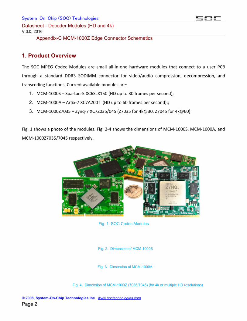
1. Product Overview
The SOC MPEG Codec Modules are small all-in-one hardware modules that connect to a user PCB
through a standard DDR3 SODIMM connector for video/audio compression, decompression, and
transcoding functions. Current available modules are:
1. MCM-1000S – Spartan-5 XC6SLX150 (HD up to 30 frames per second);
2. MCM-1000A – Artix-7 XC7A200T (HD up to 60 frames per second);;
3. MCM-1000Z7035 – Zynq-7 XC7Z035/045 (Z7035 for 4k@30, Z7045 for 4k@60)
Fig. 1 shows a photo of the modules. Fig. 2-4 shows the dimensions of MCM-1000S, MCM-1000A, and
MCM-1000Z7035/7045 respectively.
Fig. 1 SOC Codec Modules
Fig. 2. Dimension of MCM-1000S
Fig. 3. Dimension of MCM-1000A
Fig. 4. Dimension of MCM-1000Z (7035/7045) (for 4k or multiple HD resolutions)
© 2008, System-On-Chip Technologies Inc. www.soctechnologies.com Page 2
System-On-Chip (SOC) Technologies
Datasheet - Decoder Modules (HD and 4k) V.3.0, 2016
2. Connecting the Module to a User PCB
The MCM-1000 (A/S/Z) modules have identical edge pins that are compatible to standard DDR3 SODIMMconnectors. The following off-the-shelf DDR3 SODIMM connectors can be used to connect the SOC codecmodules onto a user PCB:
1. 1 MM80-204B1-1
2. MM80-204B1-1E
3. AS0A621-U2SN-7F
4. AS0A621-H2S6-7H
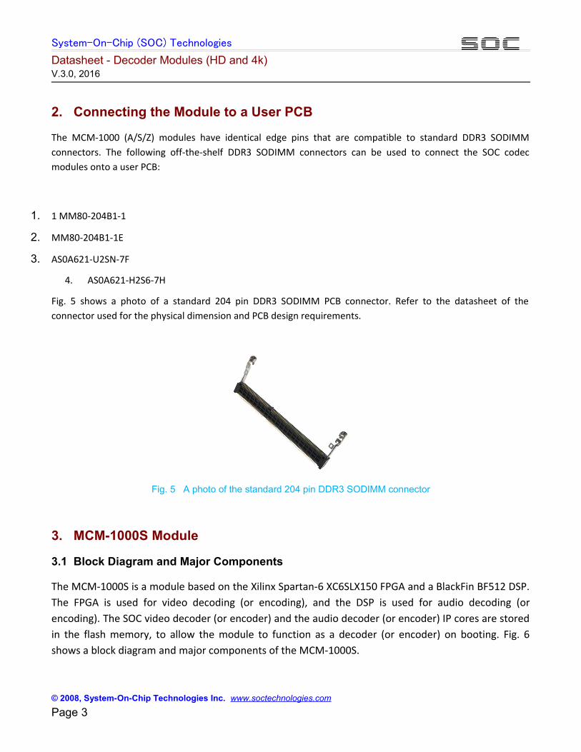
Fig. 5 shows a photo of a standard 204 pin DDR3 SODIMM PCB connector. Refer to the datasheet of theconnector used for the physical dimension and PCB design requirements.
Fig. 5 A photo of the standard 204 pin DDR3 SODIMM connector
3. MCM-1000S Module
3.1 Block Diagram and Major Components
The MCM-1000S is a module based on the Xilinx Spartan-6 XC6SLX150 FPGA and a BlackFin BF512 DSP.The FPGA is used for video decoding (or encoding), and the DSP is used for audio decoding (orencoding). The SOC video decoder (or encoder) and the audio decoder (or encoder) IP cores are storedin the flash memory, to allow the module to function as a decoder (or encoder) on booting. Fig. 6shows a block diagram and major components of the MCM-1000S.
© 2008, System-On-Chip Technologies Inc. www.soctechnologies.com Page 3
System-On-Chip (SOC) Technologies
Datasheet - Decoder Modules (HD and 4k) V.3.0, 2016
Fig. 6. MCM-1000S block diagram and major components
3.2 Standard Decoder Modules Based on MCM-1000S
Using the SOC H.264 and MPEG-2 video/audio decoder (or encoder) IP cores, the MCM-1000S can beconfigured into a series of decoder (or encoder) modules. Table-1 lists six examples of standard H.264and MPEG2 decoder modules. Refer to the Module Selection Guide for more decoder modules offeredby SOC based on the MCM-1000S. Non-standard modules are also possible according to userrequirement, with normally a minimum order quantity (MOQ).
Decoders based on the MCM-1000S module can reach up to 1080@30 resolution. Encoder modules ofhigher resolutions, such as 1080@60, are based on MCM-1000A (Atrix-7 FPGA) and/or MCM-1000Z7035/7045 (Zynq-7 FPGA), which are detailed in Section 4 of this document.
The MCM-1000Z7035/7045 can also be configured into encoders. The details of the encoder modulesare provided in the Datasheet - Encoder Modules.
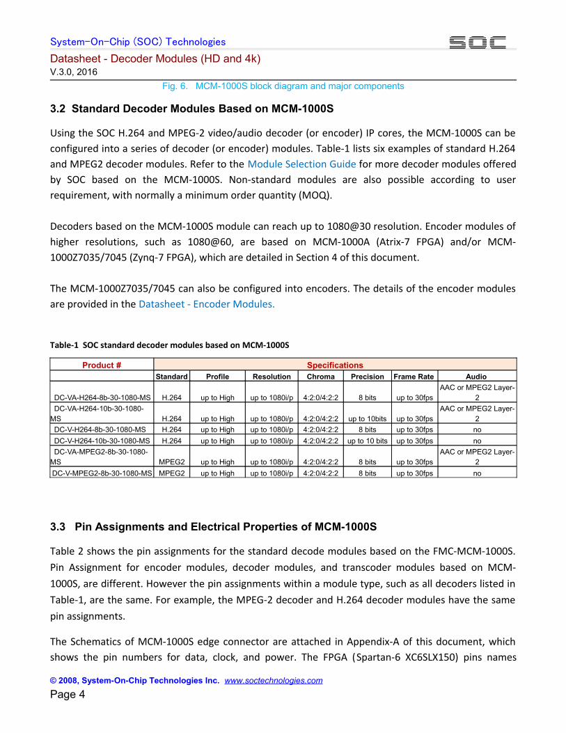
Table-1 SOC standard decoder modules based on MCM-1000S
Product # Specifications Standard Profile Resolution Chroma Precision Frame Rate Audio
DC-VA-H264-8b-30-1080-MS H.264 up to High up to 1080i/p 4:2:0/4:2:2 8 bits up to 30fpsAAC or MPEG2 Layer-
2
DC-VA-H264-10b-30-1080-MS H.264 up to High up to 1080i/p 4:2:0/4:2:2 up to 10bits up to 30fps
AAC or MPEG2 Layer-2
DC-V-H264-8b-30-1080-MS H.264 up to High up to 1080i/p 4:2:0/4:2:2 8 bits up to 30fps no
DC-V-H264-10b-30-1080-MS H.264 up to High up to 1080i/p 4:2:0/4:2:2 up to 10 bits up to 30fps no
DC-VA-MPEG2-8b-30-1080-MS MPEG2 up to High up to 1080i/p 4:2:0/4:2:2 8 bits up to 30fps
AAC or MPEG2 Layer-2
DC-V-MPEG2-8b-30-1080-MS MPEG2 up to High up to 1080i/p 4:2:0/4:2:2 8 bits up to 30fps no
3.3 Pin Assignments and Electrical Properties of MCM-1000S
Table 2 shows the pin assignments for the standard decode modules based on the FMC-MCM-1000S.Pin Assignment for encoder modules, decoder modules, and transcoder modules based on MCM-1000S, are different. However the pin assignments within a module type, such as all decoders listed inTable-1, are the same. For example, the MPEG-2 decoder and H.264 decoder modules have the samepin assignments.
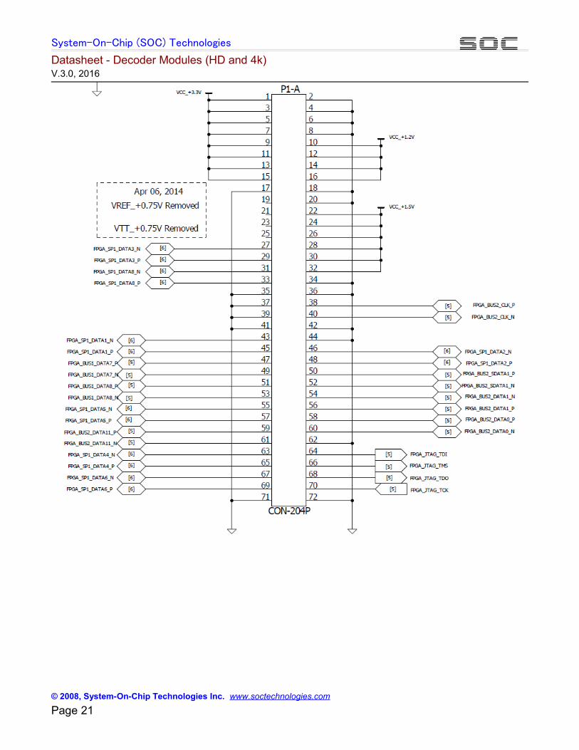
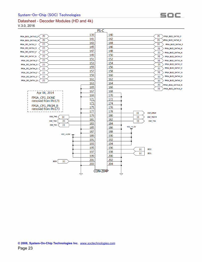
The Schematics of MCM-1000S edge connector are attached in Appendix-A of this document, whichshows the pin numbers for data, clock, and power. The FPGA (Spartan-6 XC6SLX150) pins names
© 2008, System-On-Chip Technologies Inc. www.soctechnologies.com Page 4
System-On-Chip (SOC) Technologies
Datasheet - Decoder Modules (HD and 4k) V.3.0, 2016
connected to the edge pins are also displayed in the schematics. It is noticed that the decodermodules, such as listed in Table-1, use only some of the pins that are connected to the FPGA. Theseassigned pins are listed in Table-2, below.
Table-2 also lists the FPGA pin numbers for the edge pins assigned to the standard decodermodules (listed in Table-1). Refer to the Spartan-6 XC6SLX150 Datasheet for the FPGA pins. The
Spartan-6 datasheet provides further information regarding the use of these pins, if needed (normallynot required).
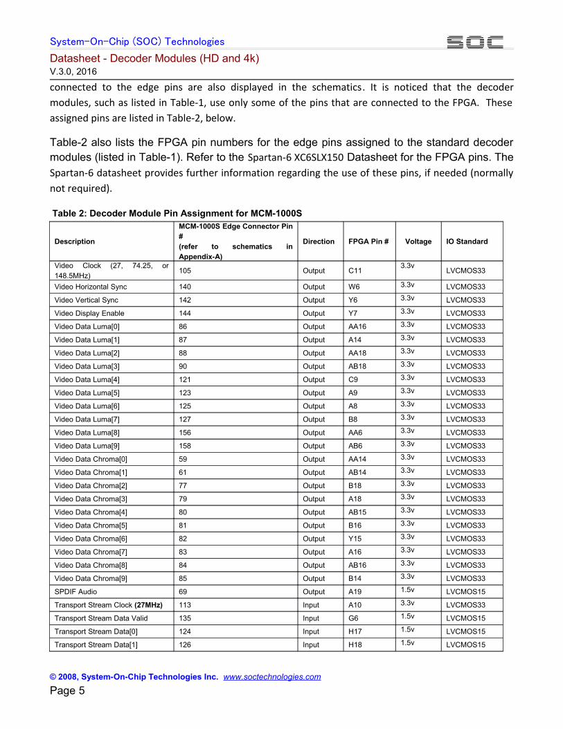
Table 2: Decoder Module Pin Assignment for MCM-1000S
Description
MCM-1000S Edge Connector Pin#(refer to schematics inAppendix-A)
Direction FPGA Pin # Voltage IO Standard
Video Clock (27, 74.25, or148.5MHz)
105 Output C113.3v
LVCMOS33
Video Horizontal Sync 140 Output W6 3.3v LVCMOS33
Video Vertical Sync 142 Output Y6 3.3v LVCMOS33
Video Display Enable 144 Output Y7 3.3v LVCMOS33
Video Data Luma[0] 86 Output AA16 3.3v LVCMOS33
Video Data Luma[1] 87 Output A14 3.3v LVCMOS33
Video Data Luma[2] 88 Output AA18 3.3v LVCMOS33
Video Data Luma[3] 90 Output AB18 3.3v LVCMOS33
Video Data Luma[4] 121 Output C9 3.3v LVCMOS33
Video Data Luma[5] 123 Output A9 3.3v LVCMOS33
Video Data Luma[6] 125 Output A8 3.3v LVCMOS33
Video Data Luma[7] 127 Output B8 3.3v LVCMOS33
Video Data Luma[8] 156 Output AA6 3.3v LVCMOS33
Video Data Luma[9] 158 Output AB6 3.3v LVCMOS33
Video Data Chroma[0] 59 Output AA14 3.3v LVCMOS33
Video Data Chroma[1] 61 Output AB14 3.3v LVCMOS33
Video Data Chroma[2] 77 Output B18 3.3v LVCMOS33
Video Data Chroma[3] 79 Output A18 3.3v LVCMOS33
Video Data Chroma[4] 80 Output AB15 3.3v LVCMOS33
Video Data Chroma[5] 81 Output B16 3.3v LVCMOS33
Video Data Chroma[6] 82 Output Y15 3.3v LVCMOS33
Video Data Chroma[7] 83 Output A16 3.3v LVCMOS33
Video Data Chroma[8] 84 Output AB16 3.3v LVCMOS33
Video Data Chroma[9] 85 Output B14 3.3v LVCMOS33
SPDIF Audio 69 Output A19 1.5v LVCMOS15
Transport Stream Clock (27MHz) 113 Input A10 3.3v LVCMOS33
Transport Stream Data Valid 135 Input G6 1.5v LVCMOS15
Transport Stream Data[0] 124 Input H17 1.5v LVCMOS15
Transport Stream Data[1] 126 Input H18 1.5v LVCMOS15
© 2008, System-On-Chip Technologies Inc. www.soctechnologies.com Page 5
System-On-Chip (SOC) Technologies
Datasheet - Decoder Modules (HD and 4k) V.3.0, 2016
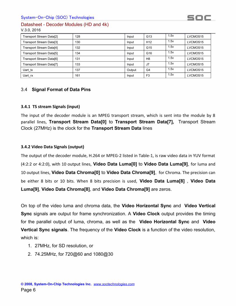
Transport Stream Data[2] 128 Input G13 1.5v LVCMOS15
Transport Stream Data[3] 130 Input H12 1.5v LVCMOS15
Transport Stream Data[4] 132 Input G15 1.5v LVCMOS15
Transport Stream Data[5] 134 Input G16 1.5v LVCMOS15
Transport Stream Data[6] 131 Input H8 1.5v LVCMOS15
Transport Stream Data[7] 133 Input J7 1.5v LVCMOS15
Uart_tx 137 Output G4 1.5v LVCMOS15
Uart_rx 161 Input F3 1.5v LVCMOS15
3.4 Signal Format of Data Pins
3.4.1 TS stream Signals (input)
The input of the decoder module is an MPEG transport stream, which is sent into the module by 8parallel lines, Transport Stream Data[0] to Transport Stream Data[7], Transport StreamClock (27MHz) is the clock for the Transport Stream Data lines
3.4.2 Video Data Signals (output)
The output of the decoder module, H.264 or MPEG-2 listed in Table-1, is raw video data in YUV format
(4:2:2 or 4:2:0), with 10 output lines, Video Data Luma[0] to Video Data Luma[9], for luma and
10 output lines, Video Data Chroma[0] to Video Data Chroma[9], for Chroma. The precision can
be either 8 bits or 10 bits. When 8 bits precision is used, Video Data Luma[8] , Video Data
Luma[9], Video Data Chroma[8], and Video Data Chroma[9] are zeros.
On top of the video luma and chroma data, the Video Horizontal Sync and Video Vertical
Sync signals are output for frame synchronization. A Video Clock output provides the timing
for the parallel output of luma, chroma, as well as the Video Horizontal Sync and Video
Vertical Sync signals. The frequency of the Video Clock is a function of the video resolution,
which is:
1. 27MHz, for SD resolution, or
2. 74.25MHz, for 720@60 and 1080@30
© 2008, System-On-Chip Technologies Inc. www.soctechnologies.com Page 6
System-On-Chip (SOC) Technologies
Datasheet - Decoder Modules (HD and 4k) V.3.0, 2016
On top of the above discussed signals, a Video Display Enable control signal is used to signify thestart and stop of the input video data.
3.4.3 Audio Data Signals (output)
The decoded audio in PCM format is sent out via the SPDIF Audio pin. Refer to the SPDIFstandard for the framing and related signal conventions.
3.4.5 Decoder Control Signals (Input and output)
Uart_rx and Uart_tx the API pins for controlling the operations of the decoder. Uart_rxreceives the command from an external control device, Uart_tx send the decoder informationto the control device. Refer to the Uart standard for details of Uart operations.
The SOC API User Manual provides the register map for the API control. Refer to the EncoderAPI User Manual for details.
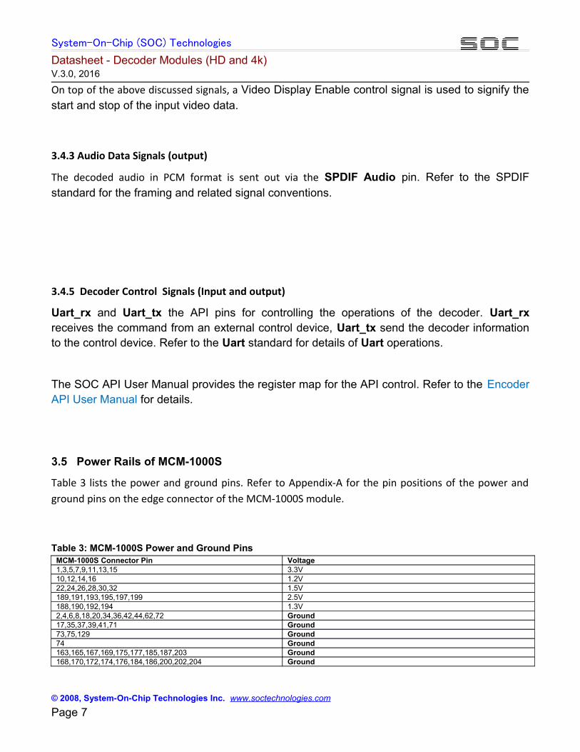
3.5 Power Rails of MCM-1000S
Table 3 lists the power and ground pins. Refer to Appendix-A for the pin positions of the power andground pins on the edge connector of the MCM-1000S module.
Table 3: MCM-1000S Power and Ground PinsMCM-1000S Connector Pin Voltage1,3,5,7,9,11,13,15 3.3V10,12,14,16 1.2V22,24,26,28,30,32 1.5V189,191,193,195,197,199 2.5V188,190,192,194 1.3V2,4,6,8,18,20,34,36,42,44,62,72 Ground17,35,37,39,41,71 Ground73,75,129 Ground74 Ground163,165,167,169,175,177,185,187,203 Ground168,170,172,174,176,184,186,200,202,204 Ground
© 2008, System-On-Chip Technologies Inc. www.soctechnologies.com Page 7
System-On-Chip (SOC) Technologies
Datasheet - Decoder Modules (HD and 4k) V.3.0, 2016
3.6 Power Requirement
The total power at operation required by a given decoder ranges from 1 to 3 watts, depending on theresolution and frame rate. Overall, it is normally below 3W.
3.7 Power Supply Amperage
All of the power rails, 1.2v, 1.3v, 1.5v, 2.5v, and 3.3v, are required to be supplied via the power pins, aslisted in Table-3. These power rails are also shown in the edge connector schematics in Appendix-A. Ithas been tested that 2A (amps) for each power rail is sufficient, although it could be much lower.
4. MCM-1000A Module
4.1 Block Diagram and Major Components
The MCM-1000A is a module based on the Xilinx Artix-7 XC7A200T FPGA and a BlackFin BF512 DSP.The FPGA is used for video decoding (or encoding), and the DSP is used for audio decoding (orencoding). The SOC video decoder (or encoder) and the audio decoder (or encoder) IP cores are storedin the flash memory, to allow the module to function as a decoder (or encoder) on booting. Fig. 7shows a block diagram and major components of the MCM-1000A.
Fig. 7. MCM-1000A block diagram and major components
4.2 Standard Decoder Modules Based on MCM-1000A
Using the SOC H.265 and H.264 video/audio decoder (or encoder) IP cores, the MCM-1000A can beconfigured into a series of decoder (or encoder) modules. Table-4 lists six examples of standard H.265and H.264 decoder modules. Refer to the Module Selection Guide for more decoder modules offeredby SOC based on the MCM-1000A. Non-standard modules, such as multiple channel decoders, are alsopossible according to user requirement, with normally minimum order quantities (MOQ).
Decoders based on the MCM-1000A module can reach up 1080@60 resolution. Decoder modules ofhigher resolutions, such as 4k@30/60, are based on MCM-1000Z (Zynq-7035/7045 FPGAs), which aredetailed in Section 5 of this document.The MCM-1000A can also be configured into encoders. The details of the encoder modules areprovided in the document of Encoder Datasheet - Encoder Modules.
Table-4 SOC standard decoder modules based on MCM-1000A
© 2008, System-On-Chip Technologies Inc. www.soctechnologies.com Page 8

System-On-Chip (SOC) Technologies
Datasheet - Decoder Modules (HD and 4k) V.3.0, 2016
Product # Specifications Standard Profile Resolution Chroma Precision Frame Rate Audio
DC-VA-H265-10b-30-1080-MA H.265 Main 12 up to 1080i/p 4:2:0/4:2:2 12 bits up to 30fps
AAC or MPEG2 Layer-2
DC-V-H265-10b-30-1080-MA H.265 Main 12 up to 1080i/p 4:2:0/4:2:2 12bits up to 30fps no
DC-VA-H265-10b-60-1080-MA H.265 Main 12 up to 1080i/p 4:2:0/4:2:2 12 bits up to 60fps
AAC or MPEG2 Layer-2
DC-V-H265-10b-60-1080-MA H.265 Main 12 up to 1080i/p 4:2:0/4:2:2 12 bits up to 60fps no
DC-VA-H264-8b-60-1080-MA H.264 up to High up to 1080i/p 4:2:0/4:2:2
8/10
bits up to 60fps
AAC or MPEG2 Layer-
2
DC-V-H264-10b-60-1080-MA H.264 up to High up to 1080i/p 4:2:0/4:2:2 8/10bits up to 60fps no
Note: DC-VA-H264-8b-30-1080-MS and DC-V-H264-10b-30-1080-MS are provided by the MCM-1000S module discussed in the previous
Section.
4.3 Pin Assignments and Electrical Properties of MCM-1000A
Table 5 shows the pin assignments for the standard decode modules based on the FMC-MCM-1000A.Pin Assignment for encoder modules based on MCM-1000A, decoder modules, and transcodermodules, are different. However the pin assignments within a module type, such as all decoders listedin Table-4, are the same. For example the H.265 decoder and H264 decoder modules have the samepin assignments.
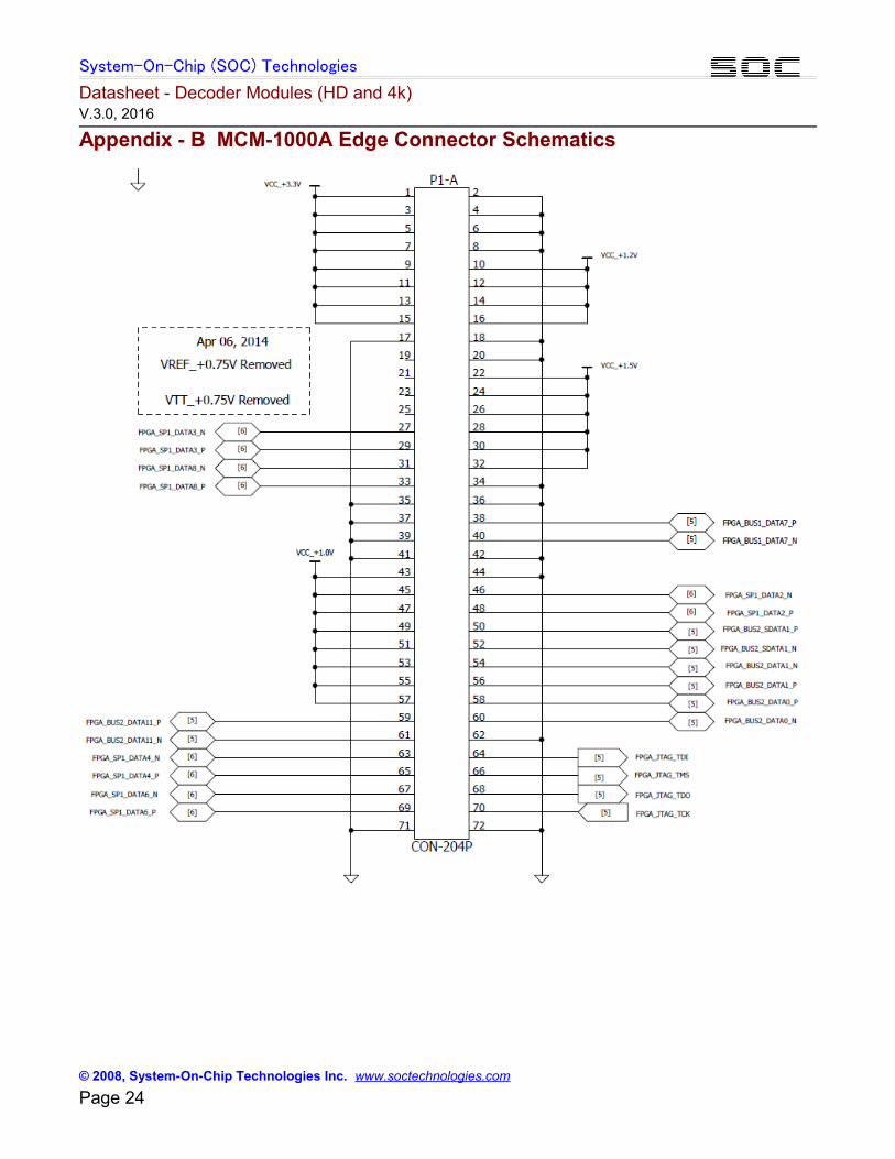
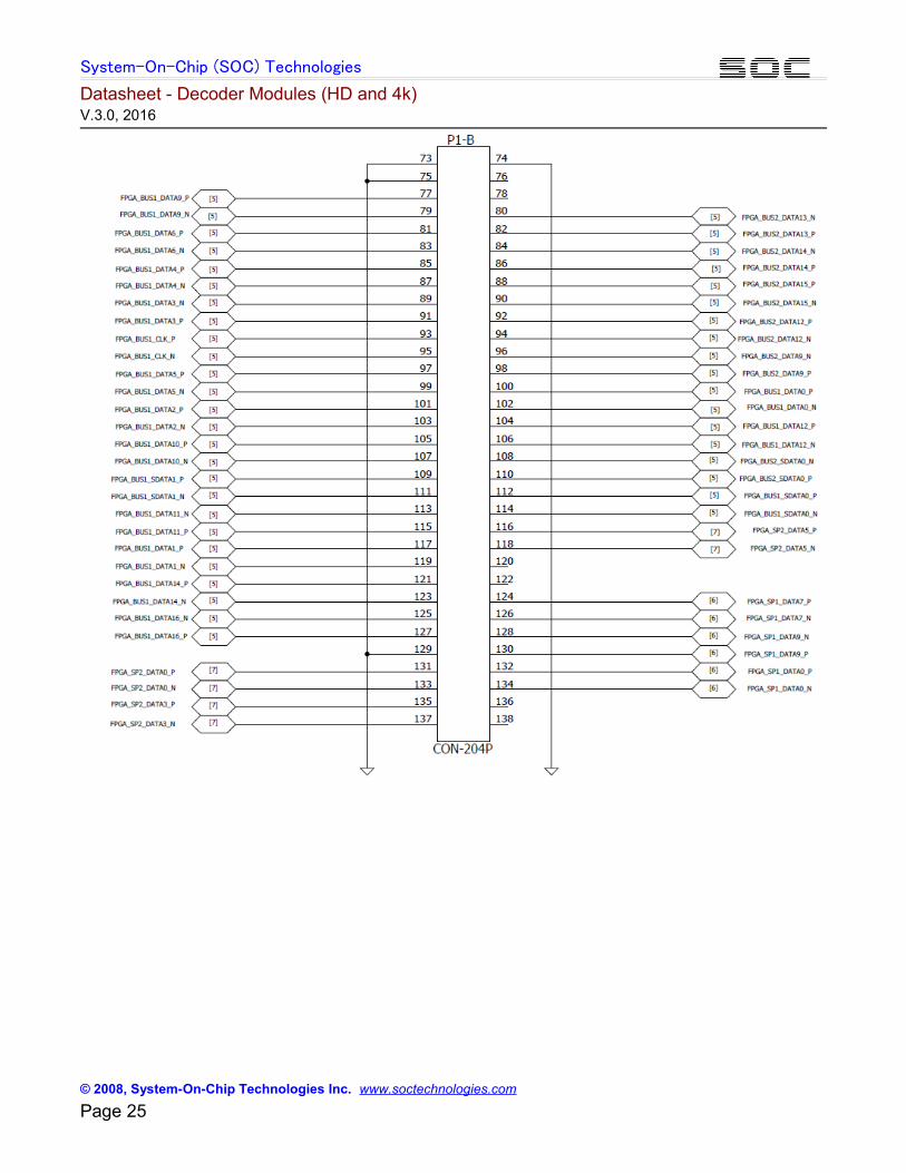
The Schematics of MCM-1000A edge connector are attached in Appendix-B of this document, whichshows the pin numbers, the power pins, and the pins connected to the FPGA (Artix-7 XC7A200T). It isnoticed that the decoder modules listed in Table-5 use only some of the pins that are connected to theFPGA. These assigned pins are listed in Table-5, below.
Table-5 also lists the FPGA pin numbers for the edge pins assigned to the decoders (listed inTable-4). The Artix-7 datasheet provides further information regarding the use of these pins.
Table 5: Decoder Module Pin Assignment for MCM-1000A
DescriptionMCM-1000A Edge ConnectorPin #
Direction FPGA Pin #Voltage
IO Standard
Video Clock 105 Output C11 3.3v LVCMOS33
Video Horizontal Sync 140 Output W6 3.3v LVCMOS33
Video Vertical Sync 142 Output Y6 3.3v LVCMOS33
Video Display Enable 144 Output Y7 3.3v LVCMOS33
Video Data Luma[0] 86 Output AA16 3.3v LVCMOS33
Video Data Luma[1] 87 Output A14 3.3v LVCMOS33
Video Data Luma[2] 88 Output AA18 3.3v LVCMOS33
Video Data Luma[3] 90 Output AB18 3.3v LVCMOS33
Video Data Luma[4] 121 Output C9 3.3v LVCMOS33
Video Data Luma[5] 123 Output A9 3.3v LVCMOS33
© 2008, System-On-Chip Technologies Inc. www.soctechnologies.com Page 9

System-On-Chip (SOC) Technologies
Datasheet - Decoder Modules (HD and 4k) V.3.0, 2016
Video Data Luma[6] 125 Output A8 3.3v LVCMOS33
Video Data Luma[7] 127 Output B8 3.3v LVCMOS33
Video Data Luma[8] 156 Output AA6 3.3v LVCMOS33
Video Data Luma[9] 158 Output AB6 3.3v LVCMOS33
Video Data Chroma[0] 59 Output AA14 3.3v LVCMOS33
Video Data Chroma[1] 61 Output AB14 3.3v LVCMOS33
Video Data Chroma[2] 77 Output B18 3.3v LVCMOS33
Video Data Chroma[3] 79 Output A18 3.3v LVCMOS33
Video Data Chroma[4] 80 Output AB15 3.3v LVCMOS33
Video Data Chroma[5] 81 Output B16 3.3v LVCMOS33
Video Data Chroma[6] 82 Output Y15 3.3v LVCMOS33
Video Data Chroma[7] 83 Output A16 3.3v LVCMOS33
Video Data Chroma[8] 84 Output AB16 3.3v LVCMOS33
Video Data Chroma[9] 85 Output B14 3.3v LVCMOS33
SPDIF Audio 69 Output A19 1.5v LVCMOS15
Transport Stream Clock 113 Input A10 3.3v LVCMOS33
Transport Stream Data Valid 135 Input G6 1.5v LVCMOS15
Transport Stream Data[0] 124 Input H17 1.5v LVCMOS15
Transport Stream Data[1] 126 Input H18 1.5v LVCMOS15
Transport Stream Data[2] 128 Input G13 1.5v LVCMOS15
Transport Stream Data[3] 130 Input H12 1.5v LVCMOS15
Transport Stream Data[4] 132 Input G15 1.5v LVCMOS15
Transport Stream Data[5] 134 Input G16 1.5v LVCMOS15
Transport Stream Data[6] 131 Input H8 1.5v LVCMOS15
Transport Stream Data[7] 133 Input J7 1.5v LVCMOS15
Uart_tx 137 Output G4 1.5v LVCMOS15
Uart_rx 161 Input F3 1.5v LVCMOS15
4.4 Signal Format of Data Pins
4.4.1 TS stream Signals (input)
The input of the decoder module is an MPEG transport stream, which is sent into the module by 8parallel lines, Transport Stream Data[0] to Transport Stream Data[7], Transport StreamClock (27MHz) is the clock for the Transport Stream Data lines
© 2008, System-On-Chip Technologies Inc. www.soctechnologies.com Page 10
System-On-Chip (SOC) Technologies
Datasheet - Decoder Modules (HD and 4k) V.3.0, 2016
4.4.2 Video Data Signals (output)
The output of the decoder module, H.264 or MPEG-2 listed in Table-1, is raw video data in YUV format
(4:2:2 or 4:2:0), with 10 output lines, Video Data Luma[0] to Video Data Luma[9], for Luma and
10 output lines, Video Data Chroma[0] to Video Data Chroma[9], for the Chroma. The precision
can be either 8 bits or 10 bits. When 8 bits precision is used, Video Data Luma[8] , Video Data
Luma[9], Video Data Chroma[8], and Video Data Chroma[9] are zeros.
On top of the video luma and chroma data, the Video Horizontal Sync and Video Vertical
Sync signals are output for frame synchronization. A Video Clock output provides the timing
for the parallel output of luma, chroma, as well as the Video Horizontal Sync and Video
Vertical Sync signals. The frequency of the Video Clock is a function of the video resolution,
which is:
1. 27MHz, for SD resolution
2. 74.25MHz, for 720@60 and 1080@30
3. 148.5MHz, for 1080@60
On top of the above discussed signals, a Video Display Enable control signal is used to signify thestart and stop of the input video data.
4.4.3 Audio Data Signals (output)
The decoded audio in PCM format is sent out via the SPDIF Audio pin. Refer to the SPDIFstandard for the framing and related signal conventions.
4.4.5 Decoder Control Signals (Input and output)
Uart_rx and Uart_tx the API pins for controlling the operations of the decoder. Uart_rxreceives the command from the external control device, Uart_tx send the decoder informationto the control device. Refer to the Uart standard for details of Uart operations.
© 2008, System-On-Chip Technologies Inc. www.soctechnologies.com Page 11
System-On-Chip (SOC) Technologies
Datasheet - Decoder Modules (HD and 4k) V.3.0, 2016
The SOC API User Manual provides the register map for the API control. Refer to the EncoderAPI User Manual for details.
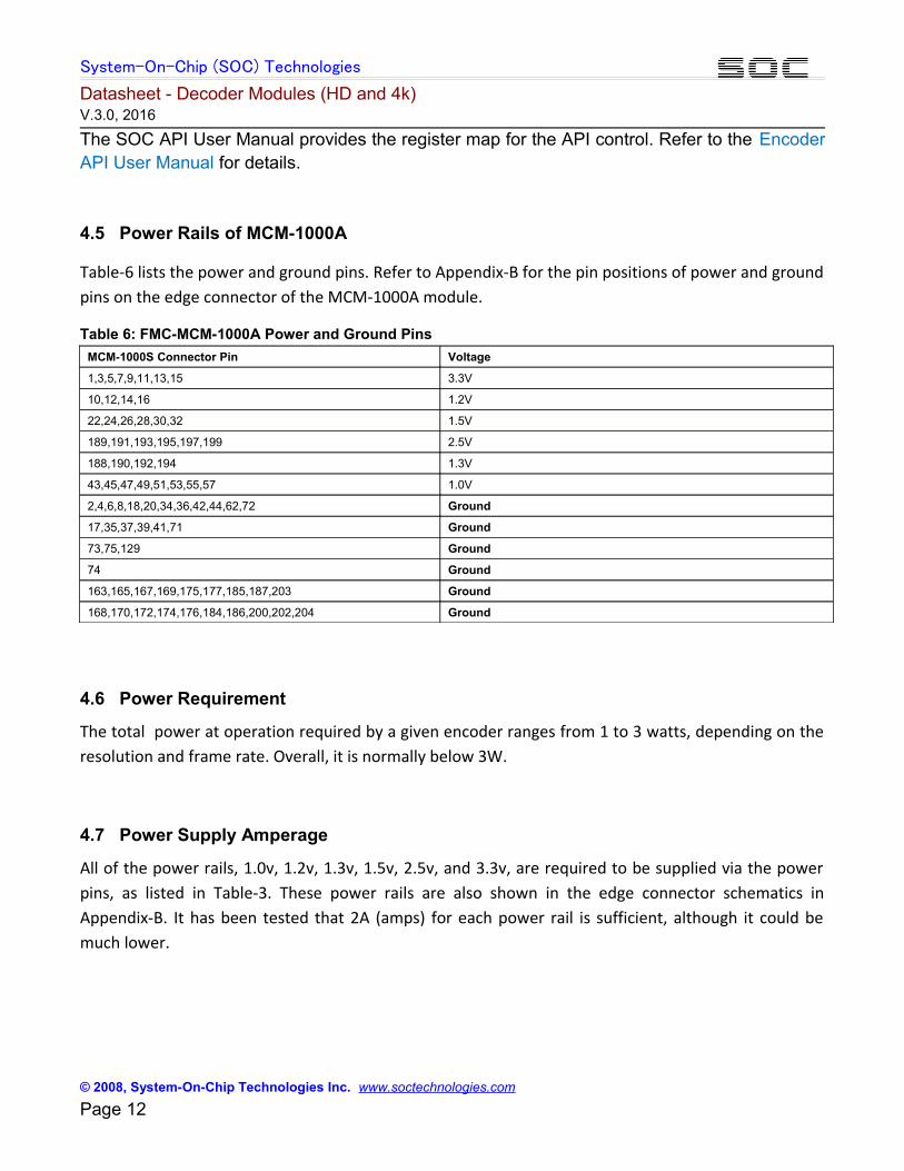
4.5 Power Rails of MCM-1000A
Table-6 lists the power and ground pins. Refer to Appendix-B for the pin positions of power and groundpins on the edge connector of the MCM-1000A module.
Table 6: FMC-MCM-1000A Power and Ground Pins
MCM-1000S Connector Pin Voltage
1,3,5,7,9,11,13,15 3.3V
10,12,14,16 1.2V
22,24,26,28,30,32 1.5V
189,191,193,195,197,199 2.5V
188,190,192,194 1.3V
43,45,47,49,51,53,55,57 1.0V
2,4,6,8,18,20,34,36,42,44,62,72 Ground
17,35,37,39,41,71 Ground
73,75,129 Ground
74 Ground
163,165,167,169,175,177,185,187,203 Ground
168,170,172,174,176,184,186,200,202,204 Ground
4.6 Power Requirement
The total power at operation required by a given encoder ranges from 1 to 3 watts, depending on theresolution and frame rate. Overall, it is normally below 3W.
4.7 Power Supply Amperage
All of the power rails, 1.0v, 1.2v, 1.3v, 1.5v, 2.5v, and 3.3v, are required to be supplied via the powerpins, as listed in Table-3. These power rails are also shown in the edge connector schematics inAppendix-B. It has been tested that 2A (amps) for each power rail is sufficient, although it could bemuch lower.
© 2008, System-On-Chip Technologies Inc. www.soctechnologies.com Page 12
System-On-Chip (SOC) Technologies
Datasheet - Decoder Modules (HD and 4k) V.3.0, 2016
5. MCM-1000Z Module
5.1 Block Diagram and Major Components
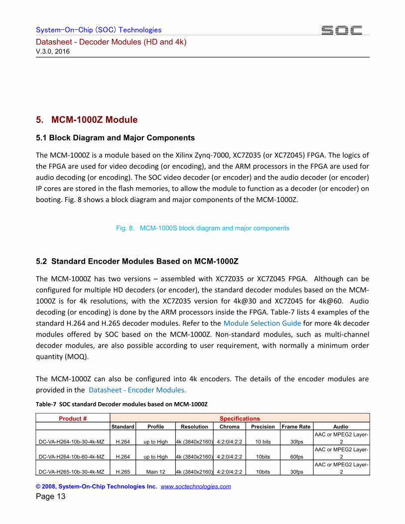
The MCM-1000Z is a module based on the Xilinx Zynq-7000, XC7Z035 (or XC7Z045) FPGA. The logics ofthe FPGA are used for video decoding (or encoding), and the ARM processors in the FPGA are used foraudio decoding (or encoding). The SOC video decoder (or encoder) and the audio decoder (or encoder)IP cores are stored in the flash memories, to allow the module to function as a decoder (or encoder) onbooting. Fig. 8 shows a block diagram and major components of the MCM-1000Z.
Fig. 8. MCM-1000S block diagram and major components
5.2 Standard Encoder Modules Based on MCM-1000Z
The MCM-1000Z has two versions – assembled with XC7Z035 or XC7Z045 FPGA. Although can beconfigured for multiple HD decoders (or encoder), the standard decoder modules based on the MCM-1000Z is for 4k resolutions, with the XC7Z035 version for 4k@30 and XC7Z045 for 4k@60. Audiodecoding (or encoding) is done by the ARM processors inside the FPGA. Table-7 lists 4 examples of thestandard H.264 and H.265 decoder modules. Refer to the Module Selection Guide for more 4k decodermodules offered by SOC based on the MCM-1000Z. Non-standard modules, such as multi-channeldecoder modules, are also possible according to user requirement, with normally a minimum orderquantity (MOQ).
The MCM-1000Z can also be configured into 4k encoders. The details of the encoder modules areprovided in the Datasheet - Encoder Modules.
Table-7 SOC standard Decoder modules based on MCM-1000Z
Product # Specifications Standard Profile Resolution Chroma Precision Frame Rate Audio
DC-VA-H264-10b-30-4k-MZ H.264 up to High 4k (3840x2160) 4:2:0/4:2:2 10 bits 30fpsAAC or MPEG2 Layer-
2
DC-VA-H264-10b-60-4k-MZ H.264 up to High 4k (3840x2160) 4:2:0/4:2:2 10bits 60fpsAAC or MPEG2 Layer-
2
DC-VA-H265-10b-30-4k-MZ H.265 Main 12 4k (3840x2160) 4:2:0/4:2:2 10bits 30fpsAAC or MPEG2 Layer-
2
© 2008, System-On-Chip Technologies Inc. www.soctechnologies.com Page 13
System-On-Chip (SOC) Technologies
Datasheet - Decoder Modules (HD and 4k) V.3.0, 2016
DC-VA-H265-10b-60-4k-MZ H.265 Main 12 4k (3840x2160) 4:2:0/4:2:2 10 bits 60fps
AAC or MPEG2 Layer-
2
5.3 Pin Assignments and Electrical Properties of MCM-1000Z
Table 8 shows the pin assignments for the standard decode modules based on the FMC-MCM-1000Z.
The Schematics of MCM-1000Z edge connector are attached in Appendix-C of this document, whichshows the pin numbers for data, the power pins. The FPGA pin names connected to the edge pins arealso displayed in the schematics, along with voltages of the pins. It is noticed that the decoder moduleslisted in Table-7 use only some of the pins that are connected to the FPGA. These assigned pins arelisted in Table-8, below.
Table-8 also lists the FPGA pin numbers for the edge pins assigned to the standard decodermodules (listed in Table-7). Refer to the XC7Z035/045 Datasheet for the FPGA pins. The
XC7Z035/045 datasheet provides further information regarding the use of these pins, if needed(normally not required).
Table 8: Decoder Module Pin Assignment for MCM-1000Z
To be added
5.4 Signal Format of Data Pins
5.4.1 TS stream Signals (input)
The input of the decoder module is an MPEG transport stream, which is sent into the module by 8parallel lines, Transport Stream Data[0] to Transport Stream Data[7], Transport StreamClock (27MHz) is the clock for the Transport Stream Data lines
5.4.2 Video Data Signals (output)
The output of the decoder module, H.264 or MPEG-2 listed in Table-1, is raw video data in YUV format
(4:2:2 or 4:2:0), with 10 output lines, Video Data Luma[0] to Video Data Luma[9], for Luma and
10 output lines, Video Data Chroma[0] to Video Data Chroma[9], for the Chroma. The precision
© 2008, System-On-Chip Technologies Inc. www.soctechnologies.com Page 14
System-On-Chip (SOC) Technologies
Datasheet - Decoder Modules (HD and 4k) V.3.0, 2016
can be either 8 bits or 10 bits. When 8 bits precision is used, Video Data Luma[8] , Video Data
Luma[9], Video Data Chroma[8], and Video Data Chroma[9] are zeros.
On top of the video luma and chroma data, the Video Horizontal Sync and Video Vertical
Sync signals are outputs for frame synchronization. A Video Clock output provides the timing
for the parallel output of luma, chroma, as well as the Video Horizontal Sync and Video
Vertical Sync signals. The frequency of the Video Clock is a function of the video resolution,
which is:
1. 27Hz, for SD resolution
2. 74.25MHz, for 720@60 and 1080@30
3. 148.5MHz, for 1080@60
4. 148.5MHz, for 4k@30 (double sampling at both rising and falling edges of the clock signal, also double data bus)
5. 297MHz, for 4k@60 (The same number of data lines as that of 4k@30)
On top of the above discussed signals, a Video Display Enable control signal is used to signify thestart and stop of the input video data.
5.4.3 Audio Data Signals (output)
The decoded audio in PCM format is sent out via the SPDIF Audio pin. Refer to the SPDIFstandard for the framing and related signal conventions.
5.4.5 Decoder Control Signals (Input and output)
Uart_rx and Uart_tx the API pins for controlling the operations of the decoder. Uart_rxreceives the command from the external control device, Uart_tx send the decoder informationto the control device. Refer to the Uart standard for details of Uart operations.
The SOC API User Manual provides the register map for the API control. Refer to the EncoderAPI User Manual for details.
© 2008, System-On-Chip Technologies Inc. www.soctechnologies.com Page 15
System-On-Chip (SOC) Technologies
Datasheet - Decoder Modules (HD and 4k) V.3.0, 2016
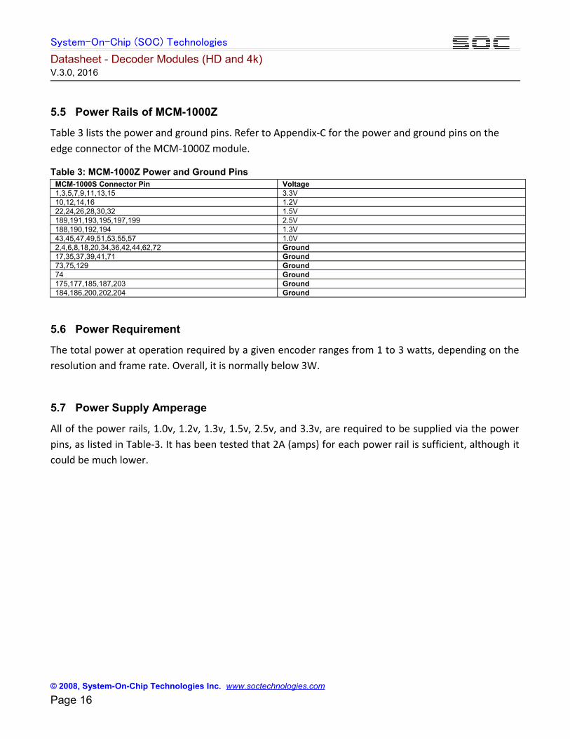
5.5 Power Rails of MCM-1000Z
Table 3 lists the power and ground pins. Refer to Appendix-C for the power and ground pins on the edge connector of the MCM-1000Z module.
Table 3: MCM-1000Z Power and Ground PinsMCM-1000S Connector Pin Voltage1,3,5,7,9,11,13,15 3.3V10,12,14,16 1.2V22,24,26,28,30,32 1.5V189,191,193,195,197,199 2.5V188,190,192,194 1.3V43,45,47,49,51,53,55,57 1.0V 2,4,6,8,18,20,34,36,42,44,62,72 Ground17,35,37,39,41,71 Ground73,75,129 Ground74 Ground175,177,185,187,203 Ground184,186,200,202,204 Ground
5.6 Power Requirement
The total power at operation required by a given encoder ranges from 1 to 3 watts, depending on theresolution and frame rate. Overall, it is normally below 3W.
5.7 Power Supply Amperage
All of the power rails, 1.0v, 1.2v, 1.3v, 1.5v, 2.5v, and 3.3v, are required to be supplied via the powerpins, as listed in Table-3. It has been tested that 2A (amps) for each power rail is sufficient, although itcould be much lower.
© 2008, System-On-Chip Technologies Inc. www.soctechnologies.com Page 16
System-On-Chip (SOC) Technologies
Datasheet - Decoder Modules (HD and 4k) V.3.0, 2016
6. Carrier Board PCB Reference DesignsSOC has several evaluation boards for evaluating the encoder and decoder modules (and for the IP
cores as well). These evaluation boards provide not only the DDR3 SODIMM connectors to connect the
encoder (and/or decoder) modules, but also commonly used digital video/audio ports, such as SDI and
HDMI. Ethernet port of tri-speed, 10/100/1000Mbps, as a network connection, is used in all of the SOC
evaluation boards.
6.1 FMC-MCM-1000 Evaluation Board
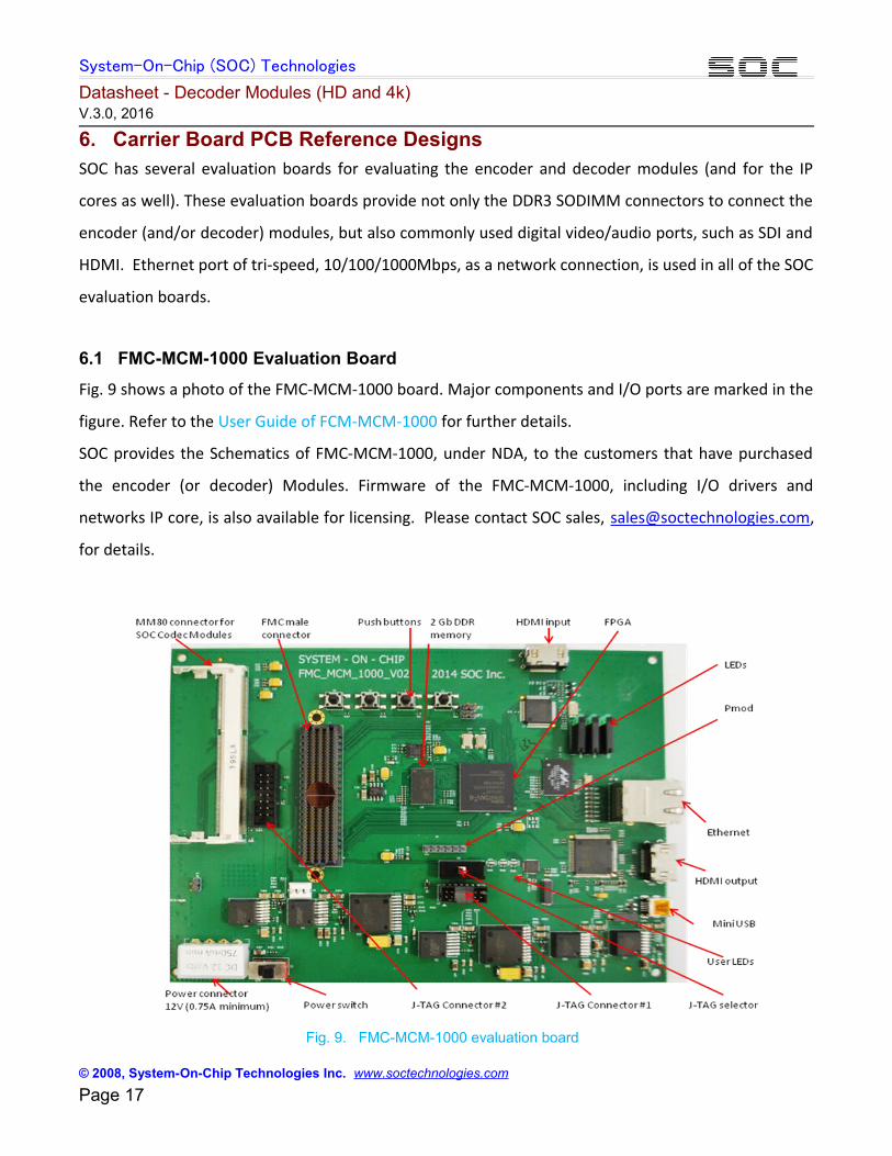
Fig. 9 shows a photo of the FMC-MCM-1000 board. Major components and I/O ports are marked in the
figure. Refer to the User Guide of FCM-MCM-1000 for further details.
SOC provides the Schematics of FMC-MCM-1000, under NDA, to the customers that have purchased
the encoder (or decoder) Modules. Firmware of the FMC-MCM-1000, including I/O drivers and
networks IP core, is also available for licensing. Please contact SOC sales, [email protected],
for details.
Fig. 9. FMC-MCM-1000 evaluation board
© 2008, System-On-Chip Technologies Inc. www.soctechnologies.com Page 17
System-On-Chip (SOC) Technologies
Datasheet - Decoder Modules (HD and 4k) V.3.0, 2016
6.2 VTR-2000 Evaluation Board
Fig. 10 and Fig 11 show the top and bottom views of the VTR-2000 board. Major components and I/O
ports are marked in the figure. Refer to the User Guide of VTR-2000 for further details.
SOC provides the Schematics of VTR-2000, under NDA, to the customers that have purchased the
encoder (or decoder) Modules. Firmware of the VTR-2000, including I/O drivers and networks IP core,
is also available for licensing. Please contact SOC sales, [email protected], for details.
Fig. 10. VTR-2000 evaluation board top view
Fig. 11. VTR-2000 evaluation board bottom view
6.3 VTR-4000 Evaluation Board
Fig. 11 and Fig 13 show the top and bottom views of the VTR-4000 board. Major components and I/O
ports are marked in the figure. Refer to the User Guide of VTR-4000 for further details.
SOC provides the Schematics of VTR-4000, under NDA, to the customers that have purchased the
encoder (or decoder) Modules. Firmware of the VTR-4000, including I/O drivers and networks IP core,
is also available for licensing. Please contact SOC sales at [email protected], for details.
Fig. 12. VTR-4000 evaluation board top view
Fig. 13. VTR-4000 evaluation board bottom view
© 2008, System-On-Chip Technologies Inc. www.soctechnologies.com Page 18
System-On-Chip (SOC) Technologies
Datasheet - Decoder Modules (HD and 4k) V.3.0, 2016
7. Ordering Information
Fig. 14 shows the product code naming convention for the SOC MPEG codec modules and IP cores. Non-standard codec modules can be ordered following the same naming format (minimum order quantity is requiredfor non-standard modules).
Fig. 14 SOC MPEG codec (IP cores and modules) product code naming convention
8. Contact Information
Please Contact SOC head office or distributor for product details or place orders.
Head Office
System-On-Chip (SOC) Technologies Inc.
60 Baffin Place
Waterloo, ON, Canada N2V 1Z7
Telephone: 1-519-880-8609
E-mail: [email protected]
9. Document Revisions
Version # Revision Date NotesV.1.0 2014/02/15 First releaseV.1.1 2015/05/10V.2.0 2016/02/25V.3.0 2016/05/20
© 2008, System-On-Chip Technologies Inc. www.soctechnologies.com Page 19
System-On-Chip (SOC) Technologies
Datasheet - Decoder Modules (HD and 4k) V.3.0, 2016
Appendix - A MCM-1000S Edge Connector Schematics
© 2008, System-On-Chip Technologies Inc. www.soctechnologies.com Page 20
System-On-Chip (SOC) Technologies
Datasheet - Decoder Modules (HD and 4k) V.3.0, 2016
© 2008, System-On-Chip Technologies Inc. www.soctechnologies.com Page 21

System-On-Chip (SOC) Technologies
Datasheet - Decoder Modules (HD and 4k) V.3.0, 2016
© 2008, System-On-Chip Technologies Inc. www.soctechnologies.com Page 22
System-On-Chip (SOC) Technologies
Datasheet - Decoder Modules (HD and 4k) V.3.0, 2016
© 2008, System-On-Chip Technologies Inc. www.soctechnologies.com Page 23
System-On-Chip (SOC) Technologies
Datasheet - Decoder Modules (HD and 4k) V.3.0, 2016
Appendix - B MCM-1000A Edge Connector Schematics
© 2008, System-On-Chip Technologies Inc. www.soctechnologies.com Page 24
System-On-Chip (SOC) Technologies
Datasheet - Decoder Modules (HD and 4k) V.3.0, 2016
© 2008, System-On-Chip Technologies Inc. www.soctechnologies.com Page 25
System-On-Chip (SOC) Technologies
Datasheet - Decoder Modules (HD and 4k) V.3.0, 2016
© 2008, System-On-Chip Technologies Inc. www.soctechnologies.com Page 26

System-On-Chip (SOC) Technologies
Datasheet - Decoder Modules (HD and 4k) V.3.0, 2016
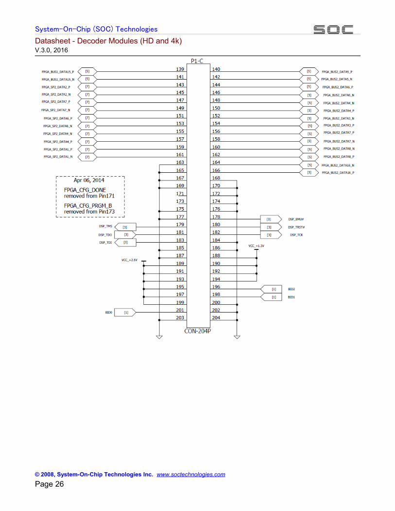
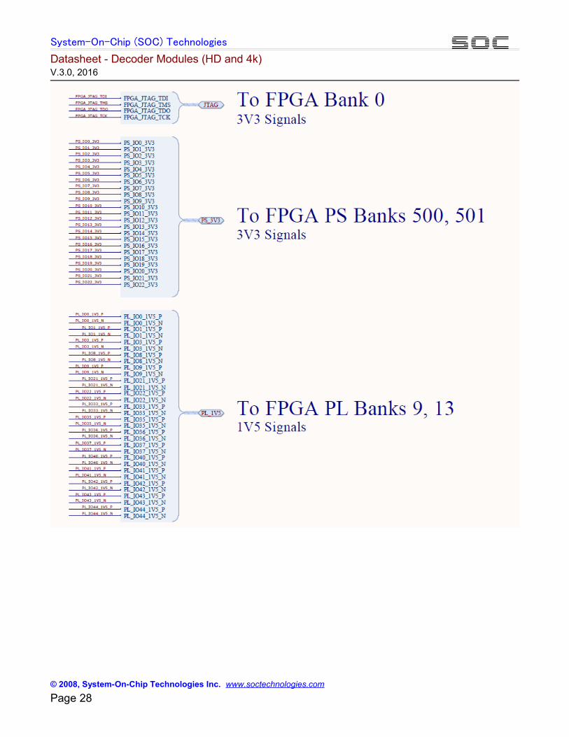
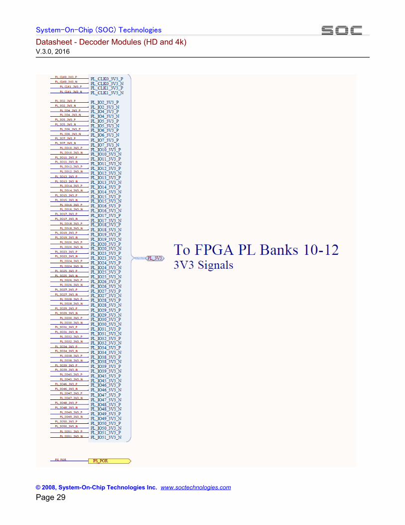
Appendix - C MCM-1000Z Edge Connector Schematics
© 2008, System-On-Chip Technologies Inc. www.soctechnologies.com Page 27
System-On-Chip (SOC) Technologies
Datasheet - Decoder Modules (HD and 4k) V.3.0, 2016
© 2008, System-On-Chip Technologies Inc. www.soctechnologies.com Page 28
System-On-Chip (SOC) Technologies
Datasheet - Decoder Modules (HD and 4k) V.3.0, 2016
© 2008, System-On-Chip Technologies Inc. www.soctechnologies.com Page 29