Embed Size (px)
Citation preview

Process Industries Data HandoverGuide - Part 2Abstract:This document contains guidelines for the types and formats ofhandover information. It forms Part 2 of the Process Industries DataHandover Guide.
Issue: 2.2
European
Process
Industries
STEP
Technical
Liaison
Executive
Author: Sheila Lewis/ Alan Thomson
This document is available from:http://www.stepcom.ncl.ac.uk/epistle/eiug/default.htm
Comments to: [email protected]
Process Industries Data Handover Guide - Part 2
Copyright NoticeThe copyright of the contents of this document is assigned to EPISTLE (the European ProcessIndustries STEP Technical Liaison Executive) and its successors. However, the contents may befreely distributed or copied, in full or in part, provided due acknowledgement is made.
Version Date Comments
0.1 97-Jul-31 Initial draft based on input from Shell & BP forrelease for wider review
0.2 98-Jan-06 Second draft based on comments received to dateand new input from BP
1.0 98-Feb-10 First released version to go on web pages for widerindustry review
2.0 1998-May-15 Rewritten by BP to emphasise guidance
2.1 1998-May-28 Revised to incorporate comments from Shell
2.2 1998-Sep-10 Final revisions based on review by EPISTLEIndustrial User Group
Process Industries Data Handover Guide - Part 2 Sep-98 i
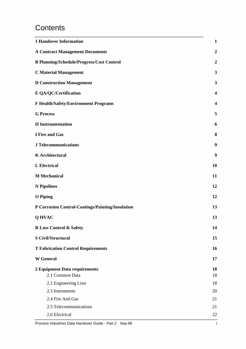
Contents
1 Handover Information 1
A Contract Management Documents 2
B Planning/Schedule/Progress/Cost Control 2
C Material Management 3
D Construction Management 3
E QA/QC/Certification 4
F Health/Safety/Environment Programs 4
G Process 5
H Instrumentation 6
I Fire and Gas 8
J Telecommunications 9
K Architectural 9
L Electrical 10
M Mechanical 11
N Pipelines 12
O Piping 12
P Corrosion Control-Coatings/Painting/Insulation 13
Q HVAC 13
R Loss Control & Safety 14
S Civil/Structural 15
T Fabrication Control Requirements 16
W General 17
2 Equipment Data requirements 182.1 Common Data 18
2.2 Engineering Lists 18
2.3 Instruments 20
2.4 Fire And Gas 21
2.5 Telecommunications 21
2.6 Electrical 22

ii Sep-98 Process Industries Data Handover Guide - Part 2
2.7 Mechanical 23
2.8 Piping 23

Process Industries Data Handover Guide - Part 2 Sep-98 1
1 Handover Information
This section lists all of the information that may be created during a project and handed over to theowner/operator. The list is not exhaustive but should identify the most common information types.Each company and each project will have to carefully evaluate their own requirements to establishtheir own handover list.
The tables also include suggested lifecycle codes and information formats. These are as describedin section 4.6.6 and section 4.5 of part 1 of this guide.
NOTE: These are suggested codes and should be regarded as a starting point only. Each userof the guide should re-assess their own requirements and edit as necessary.
In the following tables, reference is made to information handed over in structured data form.Section 2 of this part of the guide contains further details about the characteristics of informationto be handed over in this form.
In the following tables, S/D is an abbreviation for Structured Data.
2 Sep-98 Process Industries Data Handover Guide - Part 2
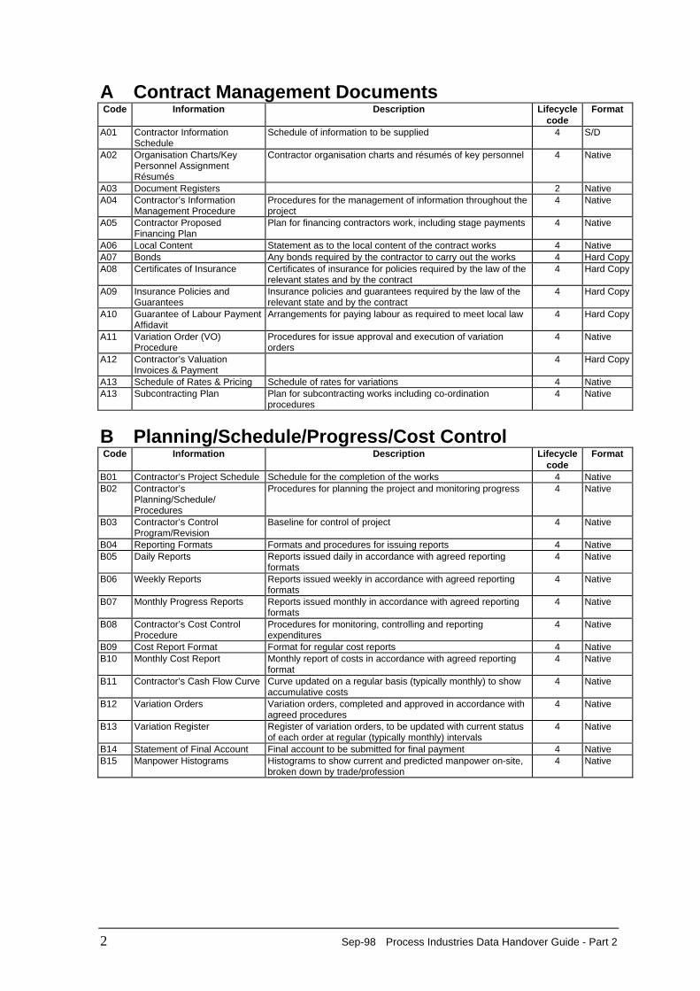
A Contract Management Documents Code Information Description Lifecycle
code Format
A01 Contractor Information
Schedule Schedule of information to be supplied 4 S/D
A02 Organisation Charts/KeyPersonnel AssignmentRésumés
Contractor organisation charts and résumés of key personnel 4 Native
A03 Document Registers 2 Native A04 Contractor’s Information
Management Procedure Procedures for the management of information throughout theproject
4 Native
A05 Contractor ProposedFinancing Plan
Plan for financing contractors work, including stage payments 4 Native
A06 Local Content Statement as to the local content of the contract works 4 Native A07 Bonds Any bonds required by the contractor to carry out the works 4 Hard Copy A08 Certificates of Insurance Certificates of insurance for policies required by the law of the
relevant states and by the contract 4 Hard Copy
A09 Insurance Policies andGuarantees
Insurance policies and guarantees required by the law of therelevant state and by the contract
4 Hard Copy
A10 Guarantee of Labour PaymentAffidavit
Arrangements for paying labour as required to meet local law 4 Hard Copy
A11 Variation Order (VO)Procedure
Procedures for issue approval and execution of variationorders
4 Native
A12 Contractor’s ValuationInvoices & Payment
4 Hard Copy
A13 Schedule of Rates & Pricing Schedule of rates for variations 4 Native A13 Subcontracting Plan Plan for subcontracting works including co-ordination
procedures 4 Native
B Planning/Schedule/Progress/Cost Control Code Information Description Lifecycle
code Format
B01 Contractor’s Project Schedule Schedule for the completion of the works 4 Native B02 Contractor’s
Planning/Schedule/Procedures
Procedures for planning the project and monitoring progress 4 Native
B03 Contractor’s ControlProgram/Revision
Baseline for control of project 4 Native
B04 Reporting Formats Formats and procedures for issuing reports 4 Native B05 Daily Reports Reports issued daily in accordance with agreed reporting
formats 4 Native
B06 Weekly Reports Reports issued weekly in accordance with agreed reportingformats
4 Native
B07 Monthly Progress Reports Reports issued monthly in accordance with agreed reportingformats
4 Native
B08 Contractor’s Cost ControlProcedure
Procedures for monitoring, controlling and reportingexpenditures
4 Native
B09 Cost Report Format Format for regular cost reports 4 Native B10 Monthly Cost Report Monthly report of costs in accordance with agreed reporting
format 4 Native
B11 Contractor’s Cash Flow Curve Curve updated on a regular basis (typically monthly) to showaccumulative costs
4 Native
B12 Variation Orders Variation orders, completed and approved in accordance withagreed procedures
4 Native
B13 Variation Register Register of variation orders, to be updated with current statusof each order at regular (typically monthly) intervals
4 Native
B14 Statement of Final Account Final account to be submitted for final payment 4 Native B15 Manpower Histograms Histograms to show current and predicted manpower on-site,
broken down by trade/profession 4 Native
Process Industries Data Handover Guide - Part 2 Sep-98 3
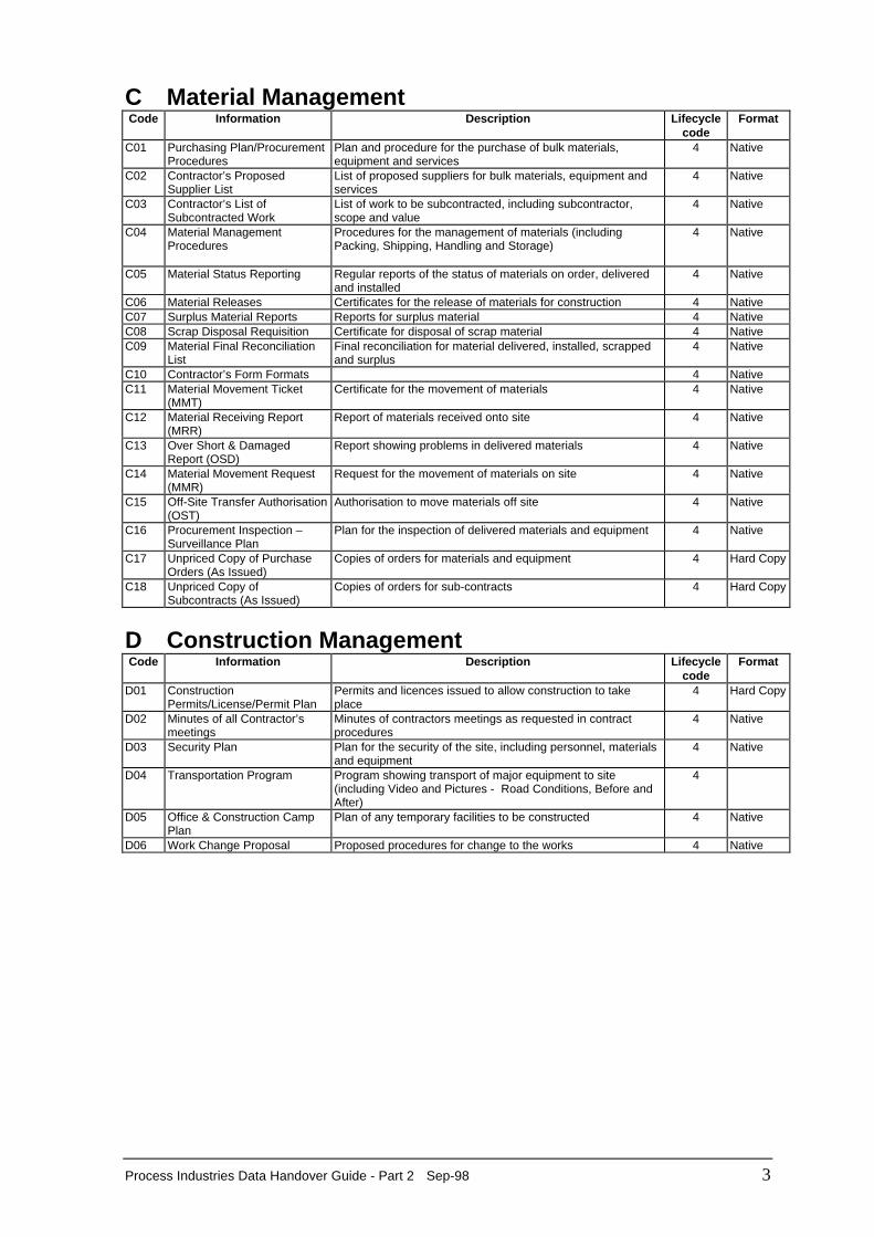
C Material Management Code Information Description Lifecycle
code Format
C01 Purchasing Plan/Procurement
Procedures Plan and procedure for the purchase of bulk materials,equipment and services
4 Native
C02 Contractor’s ProposedSupplier List
List of proposed suppliers for bulk materials, equipment andservices
4 Native
C03 Contractor’s List ofSubcontracted Work
List of work to be subcontracted, including subcontractor,scope and value
4 Native
C04 Material ManagementProcedures
Procedures for the management of materials (includingPacking, Shipping, Handling and Storage)
4 Native
C05 Material Status Reporting Regular reports of the status of materials on order, deliveredand installed
4 Native
C06 Material Releases Certificates for the release of materials for construction 4 Native C07 Surplus Material Reports Reports for surplus material 4 Native C08 Scrap Disposal Requisition Certificate for disposal of scrap material 4 Native C09 Material Final Reconciliation
List Final reconciliation for material delivered, installed, scrappedand surplus
4 Native
C10 Contractor’s Form Formats 4 Native C11 Material Movement Ticket
(MMT) Certificate for the movement of materials 4 Native
C12 Material Receiving Report(MRR)
Report of materials received onto site 4 Native
C13 Over Short & DamagedReport (OSD)
Report showing problems in delivered materials 4 Native
C14 Material Movement Request(MMR)
Request for the movement of materials on site 4 Native
C15 Off-Site Transfer Authorisation(OST)
Authorisation to move materials off site 4 Native
C16 Procurement Inspection –Surveillance Plan
Plan for the inspection of delivered materials and equipment 4 Native
C17 Unpriced Copy of PurchaseOrders (As Issued)
Copies of orders for materials and equipment 4 Hard Copy
C18 Unpriced Copy ofSubcontracts (As Issued)
Copies of orders for sub-contracts 4 Hard Copy
D Construction Management Code Information Description Lifecycle
code Format
D01 Construction
Permits/License/Permit Plan Permits and licences issued to allow construction to takeplace
4 Hard Copy
D02 Minutes of all Contractor’smeetings
Minutes of contractors meetings as requested in contractprocedures
4 Native
D03 Security Plan Plan for the security of the site, including personnel, materialsand equipment
4 Native
D04 Transportation Program Program showing transport of major equipment to site(including Video and Pictures - Road Conditions, Before andAfter)
4
D05 Office & Construction CampPlan
Plan of any temporary facilities to be constructed 4 Native
D06 Work Change Proposal Proposed procedures for change to the works 4 Native
4 Sep-98 Process Industries Data Handover Guide - Part 2
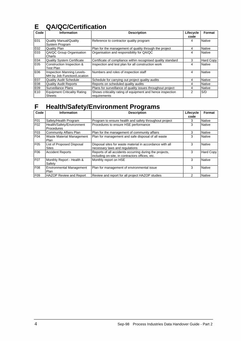
E QA/QC/Certification Code Information Description Lifecycle
code Format
E01 Quality Manual/Quality
System Program Reference to contractor quality program 4 Native
E02 Quality Plan Plan for the management of quality through the project 4 Native E03 QA/QC Group Organisation
Charts Organisation and responsibility for QA/QC 4 Native
E04 Quality System Certificate Certificate of compliance within recognised quality standard 3 Hard Copy E05 Construction Inspection &
Test Plan Inspection and test plan for all construction work 4 Native
E06 Inspection Manning Levels-MH by Job Function/Location
Numbers and roles of inspection staff 4 Native
E07 Quality Audit Schedule Schedule for carrying out project quality audits 4 Native E08 Quality Audit Reports Reports on scheduled quality audits 4 Native E09 Surveillance Plans Plans for surveillance of quality issues throughout project 4 Native E10 Equipment Criticality Rating
Sheets Shows criticality rating of equipment and hence inspectionrequirements
2 S/D
F Health/Safety/Environment Programs Code Information Description Lifecycle
code Format
F01 Safety/Health Program Program to ensure health and safety throughout project 3 Native F02 Health/Safety/Environment
Procedures Procedures to ensure HSE performance 3 Native
F03 Community Affairs Plan Plan for the management of community affairs 3 Native F04 Waste Material Management
Plan Plan for management and safe disposal of all waste 3 Native
F05 List of Proposed DisposalSites
Disposal sites for waste material in accordance with allnecessary laws and regulations
3 Native
F06 Accident Reports Reports of all accidents occurring during the projects,including on-site, in contractors offices, etc.
3 Hard Copy
F07 Monthly Report - Health &Safety
Monthly report on HSE 3 Native
F08 Environmental ManagementPlan
Plan for management of environmental issue 3 Native
F09 HAZOP Review and Report Review and report for all project HAZOP studies 2 Native
Process Industries Data Handover Guide - Part 2 Sep-98 5
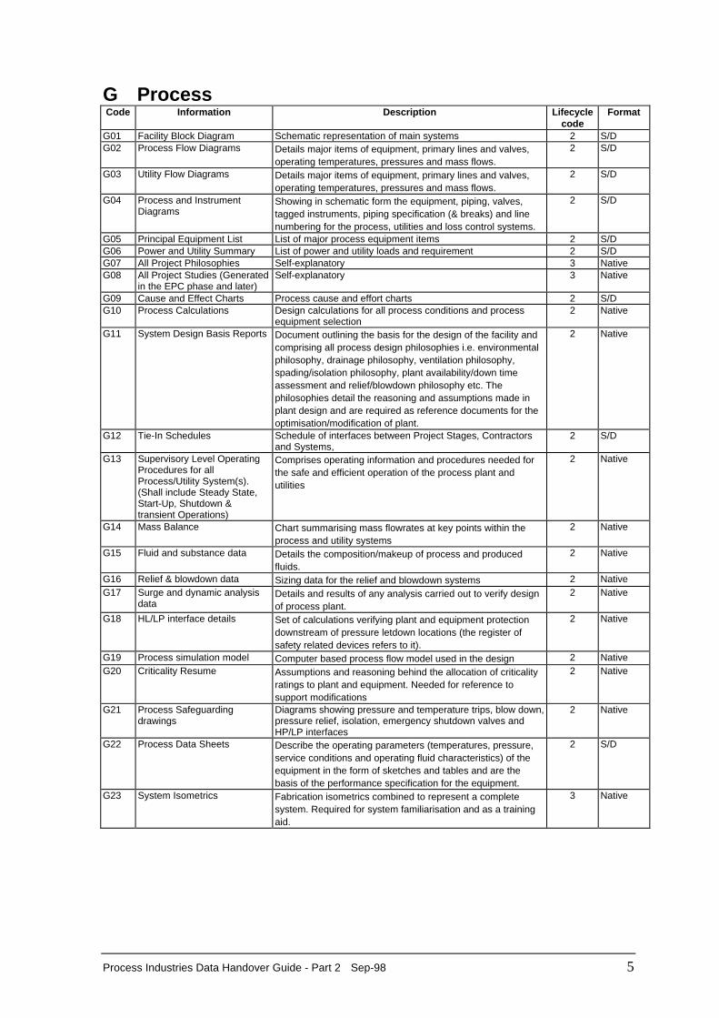
G Process Code Information Description Lifecycle
code Format
G01 Facility Block Diagram Schematic representation of main systems 2 S/D G02 Process Flow Diagrams Details major items of equipment, primary lines and valves,
operating temperatures, pressures and mass flows. 2 S/D
G03 Utility Flow Diagrams Details major items of equipment, primary lines and valves,operating temperatures, pressures and mass flows.
2 S/D
G04 Process and InstrumentDiagrams
Showing in schematic form the equipment, piping, valves,tagged instruments, piping specification (& breaks) and linenumbering for the process, utilities and loss control systems.
2 S/D
G05 Principal Equipment List List of major process equipment items 2 S/D G06 Power and Utility Summary List of power and utility loads and requirement 2 S/D G07 All Project Philosophies Self-explanatory 3 Native G08 All Project Studies (Generated
in the EPC phase and later) Self-explanatory 3 Native
G09 Cause and Effect Charts Process cause and effort charts 2 S/D G10 Process Calculations Design calculations for all process conditions and process
equipment selection 2 Native
G11 System Design Basis Reports Document outlining the basis for the design of the facility andcomprising all process design philosophies i.e. environmentalphilosophy, drainage philosophy, ventilation philosophy,spading/isolation philosophy, plant availability/down timeassessment and relief/blowdown philosophy etc. Thephilosophies detail the reasoning and assumptions made inplant design and are required as reference documents for theoptimisation/modification of plant.
2 Native
G12 Tie-In Schedules Schedule of interfaces between Project Stages, Contractorsand Systems,
2 S/D
G13 Supervisory Level OperatingProcedures for allProcess/Utility System(s).(Shall include Steady State,Start-Up, Shutdown &transient Operations)
Comprises operating information and procedures needed forthe safe and efficient operation of the process plant andutilities
2 Native
G14 Mass Balance Chart summarising mass flowrates at key points within theprocess and utility systems
2 Native
G15 Fluid and substance data Details the composition/makeup of process and producedfluids.
2 Native
G16 Relief & blowdown data Sizing data for the relief and blowdown systems 2 Native G17 Surge and dynamic analysis
data Details and results of any analysis carried out to verify designof process plant.
2 Native
G18 HL/LP interface details Set of calculations verifying plant and equipment protectiondownstream of pressure letdown locations (the register ofsafety related devices refers to it).
2 Native
G19 Process simulation model Computer based process flow model used in the design 2 Native G20 Criticality Resume Assumptions and reasoning behind the allocation of criticality
ratings to plant and equipment. Needed for reference tosupport modifications
2 Native
G21 Process Safeguardingdrawings
Diagrams showing pressure and temperature trips, blow down,pressure relief, isolation, emergency shutdown valves andHP/LP interfaces
2 Native
G22 Process Data Sheets Describe the operating parameters (temperatures, pressure,service conditions and operating fluid characteristics) of theequipment in the form of sketches and tables and are thebasis of the performance specification for the equipment.
2 S/D
G23 System Isometrics Fabrication isometrics combined to represent a completesystem. Required for system familiarisation and as a trainingaid.
3 Native
6 Sep-98 Process Industries Data Handover Guide - Part 2
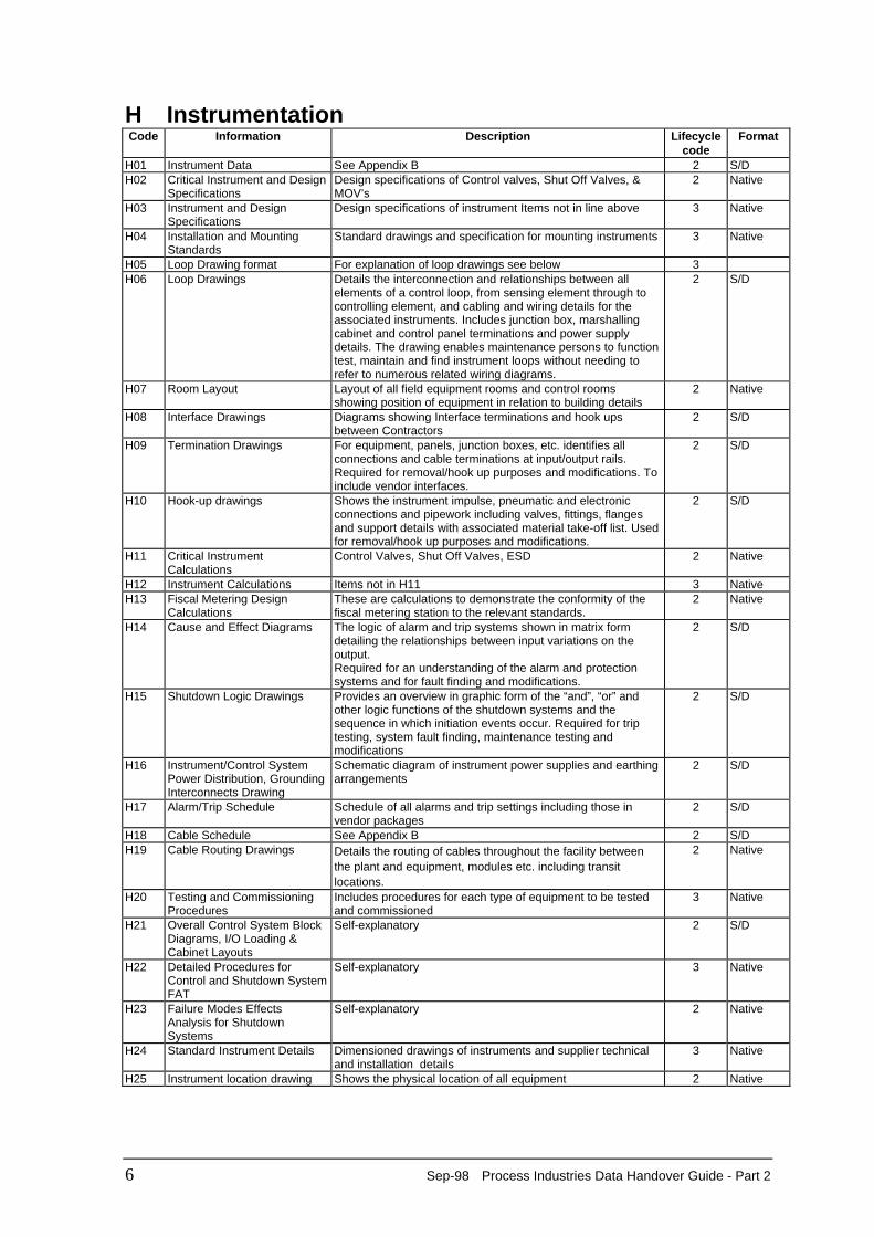
H Instrumentation Code Information Description Lifecycle
code Format
H01 Instrument Data See Appendix B 2 S/D H02 Critical Instrument and Design
Specifications Design specifications of Control valves, Shut Off Valves, &MOV’s
2 Native
H03 Instrument and DesignSpecifications
Design specifications of instrument Items not in line above 3 Native
H04 Installation and MountingStandards
Standard drawings and specification for mounting instruments 3 Native
H05 Loop Drawing format For explanation of loop drawings see below 3 H06 Loop Drawings Details the interconnection and relationships between all
elements of a control loop, from sensing element through tocontrolling element, and cabling and wiring details for theassociated instruments. Includes junction box, marshallingcabinet and control panel terminations and power supplydetails. The drawing enables maintenance persons to functiontest, maintain and find instrument loops without needing torefer to numerous related wiring diagrams.
2 S/D
H07 Room Layout Layout of all field equipment rooms and control roomsshowing position of equipment in relation to building details
2 Native
H08 Interface Drawings Diagrams showing Interface terminations and hook upsbetween Contractors
2 S/D
H09 Termination Drawings For equipment, panels, junction boxes, etc. identifies allconnections and cable terminations at input/output rails.Required for removal/hook up purposes and modifications. Toinclude vendor interfaces.
2 S/D
H10 Hook-up drawings Shows the instrument impulse, pneumatic and electronicconnections and pipework including valves, fittings, flangesand support details with associated material take-off list. Usedfor removal/hook up purposes and modifications.
2 S/D
H11 Critical InstrumentCalculations
Control Valves, Shut Off Valves, ESD 2 Native
H12 Instrument Calculations Items not in H11 3 Native H13 Fiscal Metering Design
Calculations These are calculations to demonstrate the conformity of thefiscal metering station to the relevant standards.
2 Native
H14 Cause and Effect Diagrams The logic of alarm and trip systems shown in matrix formdetailing the relationships between input variations on theoutput. Required for an understanding of the alarm and protectionsystems and for fault finding and modifications.
2 S/D
H15 Shutdown Logic Drawings Provides an overview in graphic form of the “and”, “or” andother logic functions of the shutdown systems and thesequence in which initiation events occur. Required for triptesting, system fault finding, maintenance testing andmodifications
2 S/D
H16 Instrument/Control SystemPower Distribution, GroundingInterconnects Drawing
Schematic diagram of instrument power supplies and earthingarrangements
2 S/D
H17 Alarm/Trip Schedule Schedule of all alarms and trip settings including those invendor packages
2 S/D
H18 Cable Schedule See Appendix B 2 S/D H19 Cable Routing Drawings Details the routing of cables throughout the facility between
the plant and equipment, modules etc. including transitlocations.
2 Native
H20 Testing and CommissioningProcedures
Includes procedures for each type of equipment to be testedand commissioned
3 Native
H21 Overall Control System BlockDiagrams, I/O Loading & Cabinet Layouts
Self-explanatory 2 S/D
H22 Detailed Procedures forControl and Shutdown SystemFAT
Self-explanatory 3 Native
H23 Failure Modes EffectsAnalysis for ShutdownSystems
Self-explanatory 2 Native
H24 Standard Instrument Details Dimensioned drawings of instruments and supplier technicaland installation details
3 Native
H25 Instrument location drawing Shows the physical location of all equipment 2 Native

Process Industries Data Handover Guide - Part 2 Sep-98 7
Code Information Description Lifecycle code
Format
H26 General arrangementdrawings
Shows general arrangement and locations of instrumentationand associated items on skids and within panels and cabinets.Annunciator panel GA’s shall include front fascia details alongwith full alarm text and tag numbering
2 Native
H27 Control schematic Gives a pictorial representation of the main elements andfunctions of a control circuit/system with input/output sources(switches, relays etc.) and their relationships. Details logicfunctions of the circuit/system
2 S/D
H28 SCADA/PLC/DCS Details This documents the SCADA/PLC/DCS implementationphilosophy including configuration details of inputs, outputs,logic and screen graphics, and software revision status. Thiswill include hard copy software documentation where thesoftware system is not self documenting.
2 Native
8 Sep-98 Process Industries Data Handover Guide - Part 2
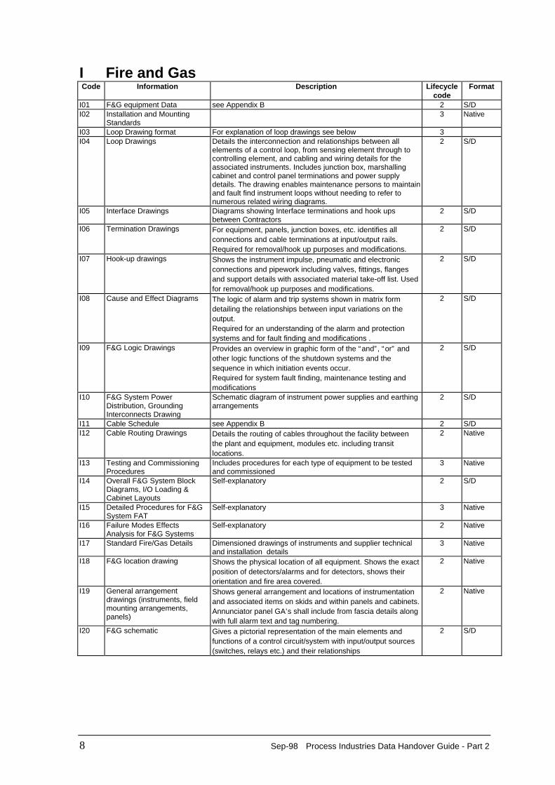
I Fire and Gas Code Information Description Lifecycle
code Format
I01 F&G equipment Data see Appendix B 2 S/D I02 Installation and Mounting
Standards 3 Native
I03 Loop Drawing format For explanation of loop drawings see below 3 I04 Loop Drawings Details the interconnection and relationships between all
elements of a control loop, from sensing element through tocontrolling element, and cabling and wiring details for theassociated instruments. Includes junction box, marshallingcabinet and control panel terminations and power supplydetails. The drawing enables maintenance persons to maintainand fault find instrument loops without needing to refer tonumerous related wiring diagrams.
2 S/D
I05 Interface Drawings Diagrams showing Interface terminations and hook upsbetween Contractors
2 S/D
I06 Termination Drawings For equipment, panels, junction boxes, etc. identifies allconnections and cable terminations at input/output rails.Required for removal/hook up purposes and modifications.
2 S/D
I07 Hook-up drawings Shows the instrument impulse, pneumatic and electronicconnections and pipework including valves, fittings, flangesand support details with associated material take-off list. Usedfor removal/hook up purposes and modifications.
2 S/D
I08 Cause and Effect Diagrams The logic of alarm and trip systems shown in matrix formdetailing the relationships between input variations on theoutput. Required for an understanding of the alarm and protectionsystems and for fault finding and modifications .
2 S/D
I09 F&G Logic Drawings Provides an overview in graphic form of the “and”, “or” andother logic functions of the shutdown systems and thesequence in which initiation events occur. Required for system fault finding, maintenance testing andmodifications
2 S/D
I10 F&G System PowerDistribution, GroundingInterconnects Drawing
Schematic diagram of instrument power supplies and earthingarrangements
2 S/D
I11 Cable Schedule see Appendix B 2 S/D I12 Cable Routing Drawings Details the routing of cables throughout the facility between
the plant and equipment, modules etc. including transitlocations.
2 Native
I13 Testing and CommissioningProcedures
Includes procedures for each type of equipment to be testedand commissioned
3 Native
I14 Overall F&G System BlockDiagrams, I/O Loading & Cabinet Layouts
Self-explanatory 2 S/D
I15 Detailed Procedures for F&GSystem FAT
Self-explanatory 3 Native
I16 Failure Modes EffectsAnalysis for F&G Systems
Self-explanatory 2 Native
I17 Standard Fire/Gas Details Dimensioned drawings of instruments and supplier technicaland installation details
3 Native
I18 F&G location drawing Shows the physical location of all equipment. Shows the exactposition of detectors/alarms and for detectors, shows theirorientation and fire area covered.
2 Native
I19 General arrangementdrawings (instruments, fieldmounting arrangements,panels)
Shows general arrangement and locations of instrumentationand associated items on skids and within panels and cabinets.Annunciator panel GA’s shall include from fascia details alongwith full alarm text and tag numbering.
2 Native
I20 F&G schematic Gives a pictorial representation of the main elements andfunctions of a control circuit/system with input/output sources(switches, relays etc.) and their relationships
2 S/D
Process Industries Data Handover Guide - Part 2 Sep-98 9
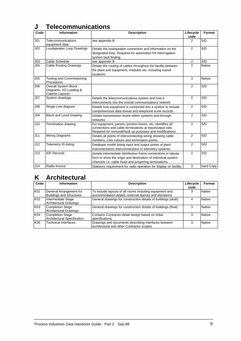
J Telecommunications Code Information Description Lifecycle
code Format
J01 Telecommunications
equipment data see appendix B 2 S/D
J02 Loudspeaker Loop Drawings Details the loudspeaker connection and information on thedesignated loop. Required for automated PA interrogationsystem fault finding.
2 S/D
J03 Cable Schedule see appendix B 2 S/D J04 Cable Routing Drawings Details the routing of cables throughout the facility between
the plant and equipment, modules etc. including transitlocations.
2 Native
J05 Testing and CommissioningProcedures
3 Native
J06 Overall System BlockDiagrams, I/O Loading &Cabinet Layouts
2 S/D
J07 System drawings Details the telecommunications system and how itinterconnects into the overall communications network
2 S/D
J08 Single Line diagram Details how equipment is connected into a system to includecomprehensive data thread and telephone trunk records.
2 S/D
J09 Block and Level Drawing Details transmission levels within systems and throughnetworks
2 S/D
J10 Termination drawing For equipment, panels, junction boxes, etc. identifies allconnections and cable terminations at input/output rails.Required for removal/hook up purposes and modifications
2 S/D
J11 Wiring Diagrams Details all points of interconnecting wiring showing cablenumbers, core colours and termination points.
2 S/D
J12 Telemetry ID listing Database model listing input and output points of plantinstrumentation interconnections to telemetry systems.
2 S/D
J13 IDF Records Details intermediate distribution frame connections in tabularform to show the origin and destination of individual systemchannels i.e. cable head and jumpering terminations.
2 S/D
J14 Radio licence Statutory requirement for radio operation for display on facility. 3 Hard Copy
K Architectural Code Information Description Lifecycle
code Format
K01 General Arrangement for
Buildings and Structures To include layouts of all rooms including equipment andaccommodation details, external layouts and elevations
3 Native
K02 Intermediate StageArchitectural Drawings
General drawings for construction details of buildings (draft) 4 Native
K03 Completion StageArchitectural Drawings
General drawings for construction details of buildings (final) 3 Native
K04 Completion StageArchitectural Specification
Contains Contractor detail design based on initialspecifications
3 Native
K05 Technical Interfaces Drawings and documents describing interfaces betweenarchitectural and other Contractor scopes
3 Native
10 Sep-98 Process Industries Data Handover Guide - Part 2
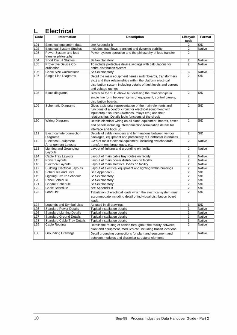
L Electrical Code Information Description Lifecycle
code Format
L01 Electrical equipment data see Appendix B 2 S/D L02 Electrical System Studies Includes load flows, transient and dynamic stability 2 Native L03 Power System and load
transfer philosophy Power system operation and the philosophy of load transfer 2
L04 Short Circuit Studies Self-explanatory 2 Native L05 Protective Device Co-
ordination To include protective device settings with calculations forentire distribution system
2 Native
L06 Cable Size Calculations Self-explanatory 3 Native L07 Single Line Diagrams Detail the main equipment items (switchboards, transformers
etc.) and their relationships within the platform electricaldistribution system including details of fault levels and currentand voltage ratings.
2 S/D
L08 Block diagrams Similar to the SLD above but detailing the relationships insingle line form between items of equipment, control panels,distribution boards.
2 S/D
L09 Schematic Diagrams Gives a pictorial representation of the main elements andfunctions of a control circuit for electrical equipment withinput/output sources (switches, relays etc.) and theirrelationships. Details logic functions of the circuit
2 S/D
L10 Wiring Diagrams Details electrical wiring on all plant, equipment, boards, boxesand panels including interconnection/termination details forinterface and hook up
2 S/D
L11 Electrical InterconnectionDiagrams
Details of cable numbers and terminations between vendorpackages, equipment and particularly at Contractor interfaces
2 S/D
L12 Electrical EquipmentArrangement Layouts
GA’s of main electrical equipment, including switchboards,transformers, large loads, etc.
2 Native
L13 Lighting and GroundingLayouts
Layout of lighting and grounding on facility 2 Native
L14 Cable Tray Layouts Layout of main cable tray routes on facility 2 Native L15 Power Layouts Layout of main power distribution on facility 2 Native L16 Electrical Layouts Layout of main electrical loads on facility 2 Native L17 Building Electrical Layouts Layout of electrical equipment and lighting within buildings 2 Native L18 Schedules and Lists See Appendix B 2 S/D L19 Lighting Fixture Schedule Self-explanatory 2 S/D L20 Panel Schedule Self-explanatory 2 S/D L21 Conduit Schedule Self-explanatory 2 S/D L22 Cable Schedule see Appendix B 2 S/D L23 Load List Tabulation of electrical loads which the electrical system must
accommodate including detail of individual distribution boardloads.
2 S/D
L24 Legends and Symbol Lists As used in all drawings 3 S/D L25 Standard Power Details Typical installation details 3 Native L26 Standard Lighting Details Typical installation details 3 Native L27 Standard Ground Details Typical installation details 3 Native L28 Standard Cable Tray Details Typical installation details 3 Native L29 Cable Routing Details the routing of cables throughout the facility between
plant and equipment, modules etc. including transit locations. 2 Native
L30 Grounding Drawings Detail grounding connections for plant and equipment andbetween modules and dissimilar structural elements
2 Native
Process Industries Data Handover Guide - Part 2 Sep-98 11
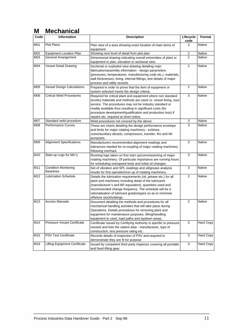
M Mechanical Code Information Description Lifecycle
code Format
M01 Plot Plans Plan view of a area showing exact location of main items of
equipment. 2 Native
M02 Equipment Location Plan Showing next level of detail from plot plan 2 Native M03 General Arrangement Dimensional drawing indicating overall extremities of plant or
equipment in plan, elevation or sectional view. 2 Native
M04 Vessel Detail Drawing Sectional or exploded view drawing detailing mainfabrication/assembly information - design parameters(pressures, temperatures, manufacturing code etc.), materials,wall thicknesses, lining, internal fittings, test details of majorprocess and utility vessels.
2 Native
M05 Vessel Design Calculations Prepared in order to prove that the item of equipment orsystem selected meets the design criteria.
2 Native
M06 Critical Weld Procedures Required for critical plant and equipment where non standard(exotic) materials and methods are used i.e. vessel lining, sourservice. The procedures may not be industry standard orreadily available thus resulting in significant costs (forprocedure development/qualification and production loss) ifrepairs etc. required at short notice.
3 Native
M07 Standard weld procedure Weld procedures not covered by the above 3 Native M08 Performance Curves These are charts detailing the design performance envelope
and limits for major rotating machinery - turbines,crane/auxiliary diesels, compressors, transfer, fire and WIpumpsets.
3 Native
M09 Alignment Specifications Manufacturers recommended alignment readings andtolerances needed for re-coupling of major rotating machineryfollowing overhaul.
3 Native
M10 Start-up Logs for M/c’s Running logs taken on first start up/commissioning of majorrotating machinery. Of particular importance are running hoursfor scheduling overspeed tests and initial oil changes.
3 Native
M11 Condition MonitoringBaselines
Set of vibration and SPL readings and oil/grease analysisresults for first operation/run up of rotating machinery.
3 Native
M12 Lubrication Schedule Details the lubrication requirements (oil, grease etc.) for allplant and machinery including detail of the lubricants(manufacturer’s and BP equivalent), quantities used andrecommended change frequency. The schedule will be arationalisation of lubricant grades/types so as to minimiseoffshore stockholdings.
2 Native
M13 Access Manuals Document detailing the methods and procedures for allmechanical handling activities that will take place duringOperations. Details procedures for removing plant andequipment for maintenance purposes, lifting/handlingequipment to used, load paths and laydown areas.
2 Native
M14 Pressure Vessel Certificate Certificate issued by Certifying Authority is specific to pressurevessels and lists the salient data - manufacturer, type ofconstruction, test pressure rating etc.
3 Hard Copy
M15 PSV Test Certificate Records details of inspection of PSV and required todemonstrate they are fit for purpose
3 Hard Copy
M16 Lifting Equipment Certificate Issued by competent third party inspector covering all portableand fixed lifting gear.
3 Hard Copy
12 Sep-98 Process Industries Data Handover Guide - Part 2
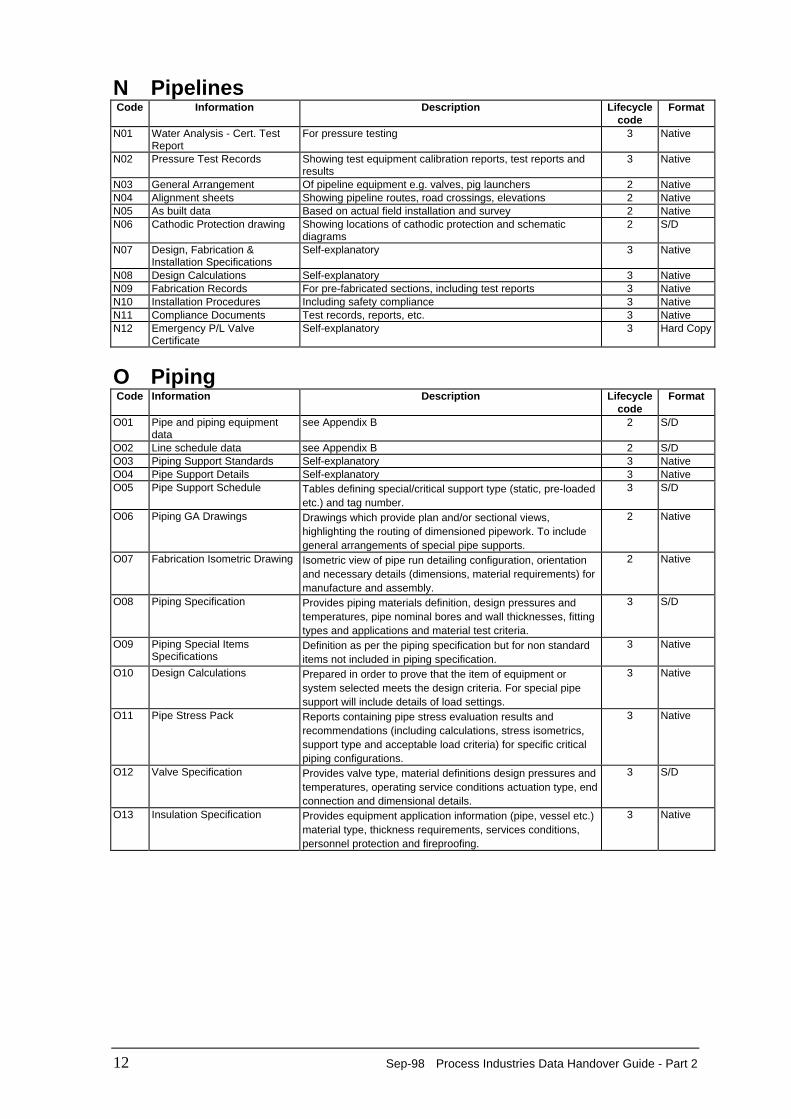
N Pipelines Code Information Description Lifecycle
code Format
N01 Water Analysis - Cert. TestReport
For pressure testing 3 Native
N02 Pressure Test Records Showing test equipment calibration reports, test reports andresults
3 Native
N03 General Arrangement Of pipeline equipment e.g. valves, pig launchers 2 Native N04 Alignment sheets Showing pipeline routes, road crossings, elevations 2 Native N05 As built data Based on actual field installation and survey 2 Native N06 Cathodic Protection drawing Showing locations of cathodic protection and schematic
diagrams 2 S/D
N07 Design, Fabrication &Installation Specifications
Self-explanatory 3 Native
N08 Design Calculations Self-explanatory 3 Native N09 Fabrication Records For pre-fabricated sections, including test reports 3 Native N10 Installation Procedures Including safety compliance 3 Native N11 Compliance Documents Test records, reports, etc. 3 Native N12 Emergency P/L Valve
Certificate Self-explanatory 3 Hard Copy
O Piping Code Information Description Lifecycle
code Format
O01 Pipe and piping equipment
data see Appendix B 2 S/D
O02 Line schedule data see Appendix B 2 S/D O03 Piping Support Standards Self-explanatory 3 Native O04 Pipe Support Details Self-explanatory 3 Native O05 Pipe Support Schedule Tables defining special/critical support type (static, pre-loaded
etc.) and tag number. 3 S/D
O06 Piping GA Drawings Drawings which provide plan and/or sectional views,highlighting the routing of dimensioned pipework. To includegeneral arrangements of special pipe supports.
2 Native
O07 Fabrication Isometric Drawing Isometric view of pipe run detailing configuration, orientationand necessary details (dimensions, material requirements) formanufacture and assembly.
2 Native
O08 Piping Specification Provides piping materials definition, design pressures andtemperatures, pipe nominal bores and wall thicknesses, fittingtypes and applications and material test criteria.
3 S/D
O09 Piping Special ItemsSpecifications
Definition as per the piping specification but for non standarditems not included in piping specification.
3 Native
O10 Design Calculations Prepared in order to prove that the item of equipment orsystem selected meets the design criteria. For special pipesupport will include details of load settings.
3 Native
O11 Pipe Stress Pack Reports containing pipe stress evaluation results andrecommendations (including calculations, stress isometrics,support type and acceptable load criteria) for specific criticalpiping configurations.
3 Native
O12 Valve Specification Provides valve type, material definitions design pressures andtemperatures, operating service conditions actuation type, endconnection and dimensional details.
3 S/D
O13 Insulation Specification Provides equipment application information (pipe, vessel etc.)material type, thickness requirements, services conditions,personnel protection and fireproofing.
3 Native
Process Industries Data Handover Guide - Part 2 Sep-98 13
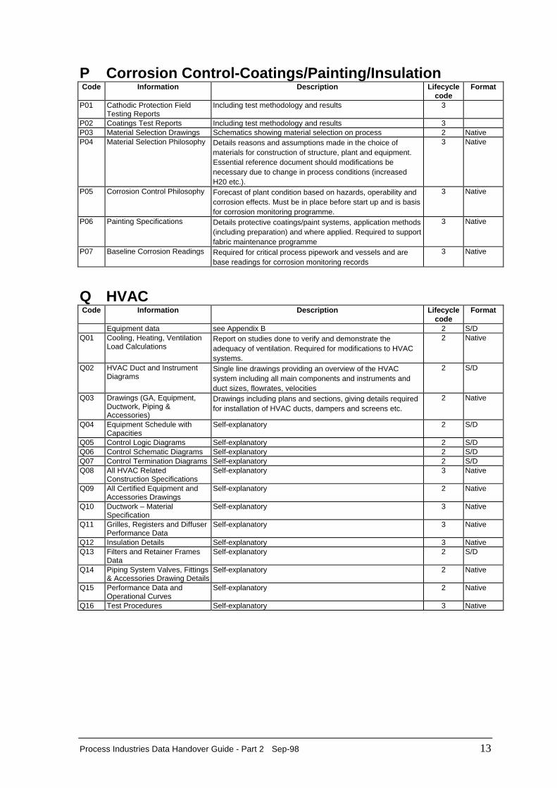
P Corrosion Control-Coatings/Painting/Insulation Code Information Description Lifecycle
code Format
P01 Cathodic Protection Field
Testing Reports Including test methodology and results 3
P02 Coatings Test Reports Including test methodology and results 3 P03 Material Selection Drawings Schematics showing material selection on process 2 Native P04 Material Selection Philosophy Details reasons and assumptions made in the choice of
materials for construction of structure, plant and equipment.Essential reference document should modifications benecessary due to change in process conditions (increasedH20 etc.).
3 Native
P05 Corrosion Control Philosophy Forecast of plant condition based on hazards, operability andcorrosion effects. Must be in place before start up and is basisfor corrosion monitoring programme.
3 Native
P06 Painting Specifications Details protective coatings/paint systems, application methods(including preparation) and where applied. Required to supportfabric maintenance programme
3 Native
P07 Baseline Corrosion Readings Required for critical process pipework and vessels and arebase readings for corrosion monitoring records
3 Native
Q HVAC Code Information Description Lifecycle
code Format
Equipment data see Appendix B 2 S/D Q01 Cooling, Heating, Ventilation
Load Calculations Report on studies done to verify and demonstrate theadequacy of ventilation. Required for modifications to HVACsystems.
2 Native
Q02 HVAC Duct and InstrumentDiagrams
Single line drawings providing an overview of the HVACsystem including all main components and instruments andduct sizes, flowrates, velocities
2 S/D
Q03 Drawings (GA, Equipment,Ductwork, Piping &Accessories)
Drawings including plans and sections, giving details requiredfor installation of HVAC ducts, dampers and screens etc.
2 Native
Q04 Equipment Schedule withCapacities
Self-explanatory 2 S/D
Q05 Control Logic Diagrams Self-explanatory 2 S/D Q06 Control Schematic Diagrams Self-explanatory 2 S/D Q07 Control Termination Diagrams Self-explanatory 2 S/D Q08 All HVAC Related
Construction Specifications Self-explanatory 3 Native
Q09 All Certified Equipment andAccessories Drawings
Self-explanatory 2 Native
Q10 Ductwork – MaterialSpecification
Self-explanatory 3 Native
Q11 Grilles, Registers and DiffuserPerformance Data
Self-explanatory 3 Native
Q12 Insulation Details Self-explanatory 3 Native Q13 Filters and Retainer Frames
Data Self-explanatory 2 S/D
Q14 Piping System Valves, Fittings& Accessories Drawing Details
Self-explanatory 2 Native
Q15 Performance Data andOperational Curves
Self-explanatory 2 Native
Q16 Test Procedures Self-explanatory 3 Native
14 Sep-98 Process Industries Data Handover Guide - Part 2
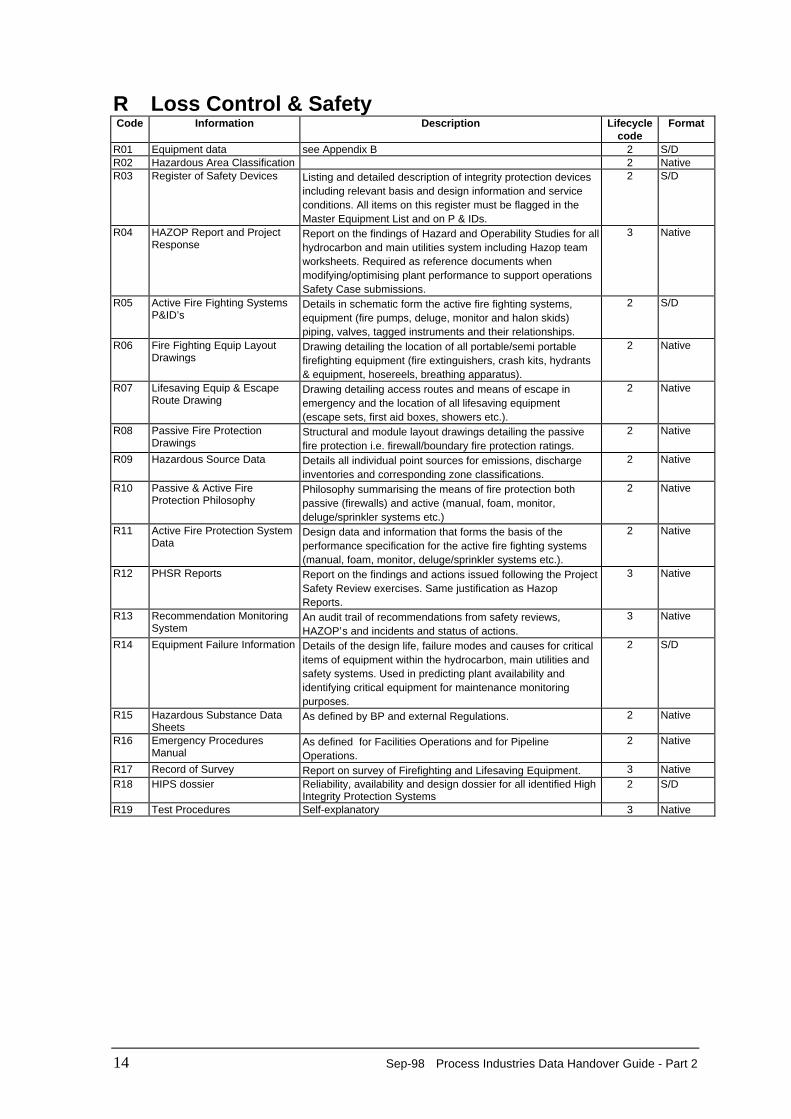
R Loss Control & Safety Code Information Description Lifecycle
code Format
R01 Equipment data see Appendix B 2 S/D R02 Hazardous Area Classification 2 Native R03 Register of Safety Devices Listing and detailed description of integrity protection devices
including relevant basis and design information and serviceconditions. All items on this register must be flagged in theMaster Equipment List and on P & IDs.
2 S/D
R04 HAZOP Report and ProjectResponse
Report on the findings of Hazard and Operability Studies for allhydrocarbon and main utilities system including Hazop teamworksheets. Required as reference documents whenmodifying/optimising plant performance to support operationsSafety Case submissions.
3 Native
R05 Active Fire Fighting SystemsP&ID’s
Details in schematic form the active fire fighting systems,equipment (fire pumps, deluge, monitor and halon skids)piping, valves, tagged instruments and their relationships.
2 S/D
R06 Fire Fighting Equip LayoutDrawings
Drawing detailing the location of all portable/semi portablefirefighting equipment (fire extinguishers, crash kits, hydrants& equipment, hosereels, breathing apparatus).
2 Native
R07 Lifesaving Equip & EscapeRoute Drawing
Drawing detailing access routes and means of escape inemergency and the location of all lifesaving equipment(escape sets, first aid boxes, showers etc.).
2 Native
R08 Passive Fire ProtectionDrawings
Structural and module layout drawings detailing the passivefire protection i.e. firewall/boundary fire protection ratings.
2 Native
R09 Hazardous Source Data Details all individual point sources for emissions, dischargeinventories and corresponding zone classifications.
2 Native
R10 Passive & Active FireProtection Philosophy
Philosophy summarising the means of fire protection bothpassive (firewalls) and active (manual, foam, monitor,deluge/sprinkler systems etc.)
2 Native
R11 Active Fire Protection SystemData
Design data and information that forms the basis of theperformance specification for the active fire fighting systems(manual, foam, monitor, deluge/sprinkler systems etc.).
2 Native
R12 PHSR Reports Report on the findings and actions issued following the ProjectSafety Review exercises. Same justification as HazopReports.
3 Native
R13 Recommendation MonitoringSystem
An audit trail of recommendations from safety reviews,HAZOP’s and incidents and status of actions.
3 Native
R14 Equipment Failure Information Details of the design life, failure modes and causes for criticalitems of equipment within the hydrocarbon, main utilities andsafety systems. Used in predicting plant availability andidentifying critical equipment for maintenance monitoringpurposes.
2 S/D
R15 Hazardous Substance DataSheets
As defined by BP and external Regulations. 2 Native
R16 Emergency ProceduresManual
As defined for Facilities Operations and for PipelineOperations.
2 Native
R17 Record of Survey Report on survey of Firefighting and Lifesaving Equipment. 3 Native R18 HIPS dossier Reliability, availability and design dossier for all identified High
Integrity Protection Systems 2 S/D
R19 Test Procedures Self-explanatory 3 Native
Process Industries Data Handover Guide - Part 2 Sep-98 15
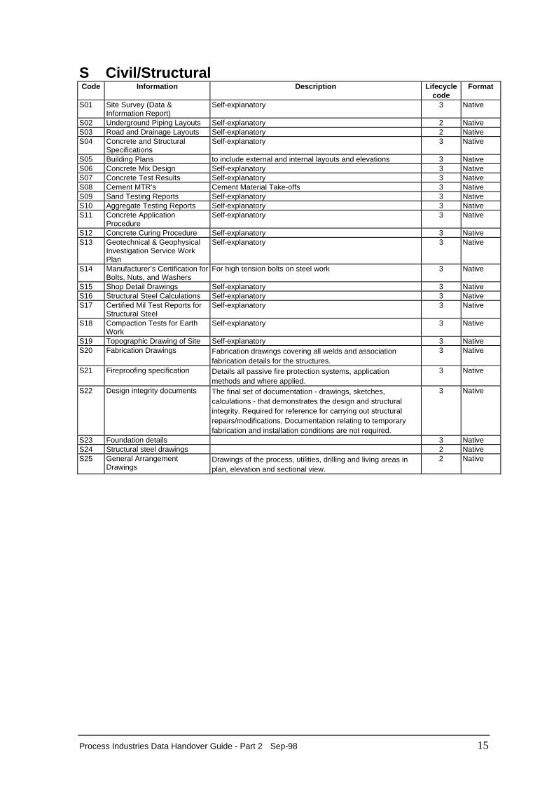
S Civil/Structural Code Information Description Lifecycle
code Format
S01 Site Survey (Data &
Information Report) Self-explanatory 3 Native
S02 Underground Piping Layouts Self-explanatory 2 Native S03 Road and Drainage Layouts Self-explanatory 2 Native S04 Concrete and Structural
Specifications Self-explanatory 3 Native
S05 Building Plans to include external and internal layouts and elevations 3 Native S06 Concrete Mix Design Self-explanatory 3 Native S07 Concrete Test Results Self-explanatory 3 Native S08 Cement MTR’s Cement Material Take-offs 3 Native S09 Sand Testing Reports Self-explanatory 3 Native S10 Aggregate Testing Reports Self-explanatory 3 Native S11 Concrete Application
Procedure Self-explanatory 3 Native
S12 Concrete Curing Procedure Self-explanatory 3 Native S13 Geotechnical & Geophysical
Investigation Service WorkPlan
Self-explanatory 3 Native
S14 Manufacturer’s Certification forBolts, Nuts, and Washers
For high tension bolts on steel work 3 Native
S15 Shop Detail Drawings Self-explanatory 3 Native S16 Structural Steel Calculations Self-explanatory 3 Native S17 Certified Mil Test Reports for
Structural Steel Self-explanatory 3 Native
S18 Compaction Tests for EarthWork
Self-explanatory 3 Native
S19 Topographic Drawing of Site Self-explanatory 3 Native S20 Fabrication Drawings Fabrication drawings covering all welds and association
fabrication details for the structures. 3 Native
S21 Fireproofing specification Details all passive fire protection systems, applicationmethods and where applied.
3 Native
S22 Design integrity documents The final set of documentation - drawings, sketches,calculations - that demonstrates the design and structuralintegrity. Required for reference for carrying out structuralrepairs/modifications. Documentation relating to temporaryfabrication and installation conditions are not required.
3 Native
S23 Foundation details 3 Native S24 Structural steel drawings 2 Native S25 General Arrangement
Drawings Drawings of the process, utilities, drilling and living areas inplan, elevation and sectional view.
2 Native
16 Sep-98 Process Industries Data Handover Guide - Part 2
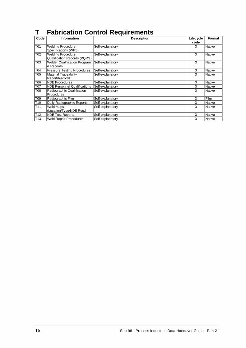
T Fabrication Control Requirements Code Information Description Lifecycle
code Format
T01 Welding Procedure
Specifications (WPS) Self-explanatory 3 Native
T02 Welding ProcedureQualification Records (PQR’s)
Self-explanatory 3 Native
T03 Welder Qualification Program& Records
Self-explanatory 3 Native
T04 Pressure Testing Procedures Self-explanatory 3 Native T05 Material Traceability
Report/Records Self-explanatory 3 Native
T06 NDE Procedures Self-explanatory 3 Native T07 NDE Personnel Qualifications Self-explanatory 3 Native T08 Radiographic Qualification
Procedures Self-explanatory 3 Native
T09 Radiographic Film Self-explanatory 3 Film T10 Daily Radiographic Reports Self-explanatory 3 Native T11 Weld Maps
(Location/Type/NDE Req.) Self-explanatory 3 Native
T12 NDE Test Reports Self-explanatory 3 Native T13 Weld Repair Procedures Self-explanatory 3 Native
Process Industries Data Handover Guide - Part 2 Sep-98 17
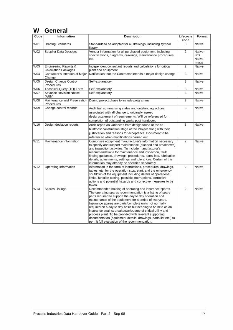
W General Code Information Description Lifecycle
code Format
W01 Drafting Standards Standards to be adopted for all drawings, including symbollibrary
3 Native
W02 Supplier Data Dossiers Vendor information for all purchased equipment, includingspecifications, diagrams, drawings, maintenance procedures,etc.
2 Native S/D Native Image
W03 Engineering Reports &Calculation Packages
Independent consultant reports and calculations for criticalplant and equipment
2 Native
W04 Contractor’s Intention of MajorChange
Notification that the Contractor intends a major design change 3 Native
W05 Design Change ControlProcedures
Self-explanatory 3 Native
W06 Technical Query (TQ) Form Self-explanatory 3 Native W07 Advance Revision Notice
(ARN) Self-explanatory 3 Native
W08 Maintenance and PreservationProcedures
During project phase to include programme 3 Native
W09 Change control records Audit trail summarising status and outstanding actionsassociated with all change to originally agreeddesign/statement of requirements. Will be referenced forcompletion of outstanding works post handover.
3 Native
W10 Design deviation reports Audit report on variances from design found at the asbuilt/post construction stage of the Project along with theirjustification and reasons for acceptance. Document to bereferenced when modifications carried out.
3 Native
W11 Maintenance Information Comprises equipment manufacturer’s information necessaryto specify and support maintenance (planned and breakdown)and inspection activities. To include manufacturer’srecommendations for maintenance and inspection, faultfinding guidance, drawings, procedures, parts lists, lubricationdetails, adjustments, settings and tolerances. Certain of thisinformation may already be specified separately
2 Native
W12 Operating Information Information in the form of instructions, procedures, drawings,tables, etc. for the operation stop, start, and the emergencyshutdown of the equipment including details of operationallimits, function testing, possible interruptions, correctiveactions and potential hazards and corrective measures to betaken.
2 Native
W13 Spares Listings Recommended holding of operating and insurance spares.The operating spares recommendation is a listing of spareparts required to support the day to day operation andmaintenance of the equipment for a period of two years.Insurance spares are parts/complete units not normallyrequired on a day to day basis but needing to be held as aninsurance against breakdown/outage of critical utility andprocess plant. To be provided with relevant supportingdocumentation (equipment details, drawings, parts list etc.) topermit full evaluation of the recommendation.
2 Native
18 Sep-98 Process Industries Data Handover Guide - Part 2
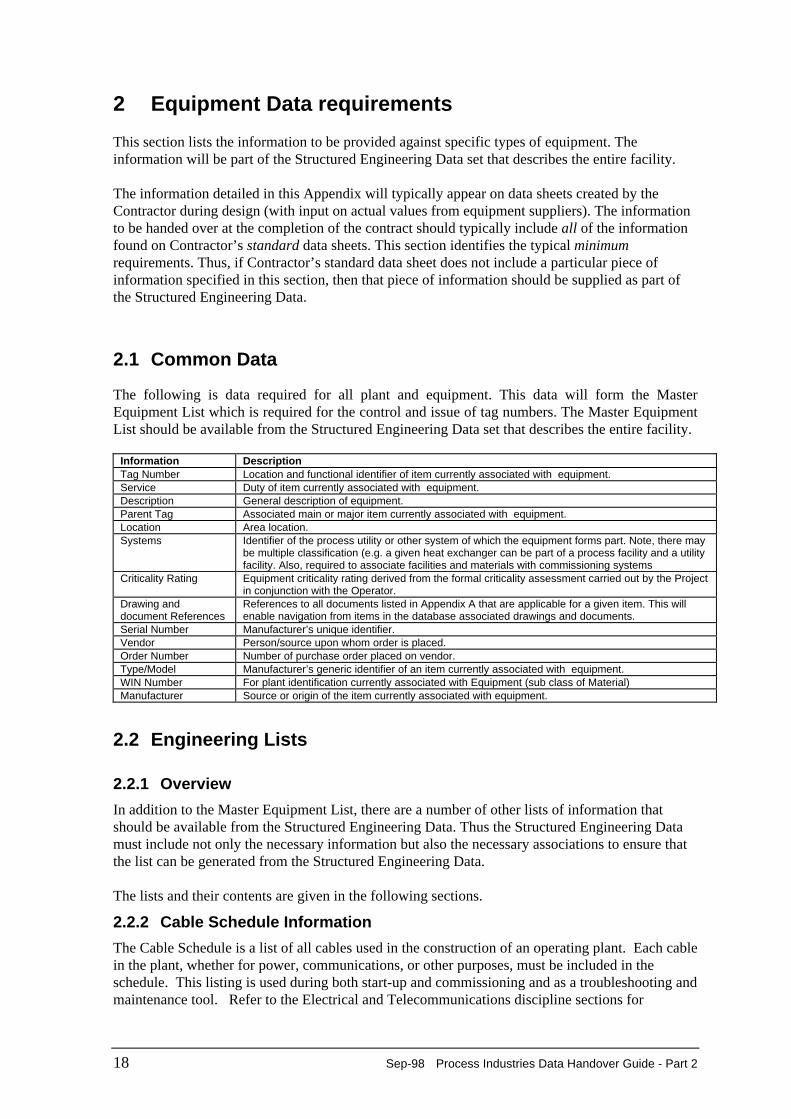
2 Equipment Data requirements This section lists the information to be provided against specific types of equipment. Theinformation will be part of the Structured Engineering Data set that describes the entire facility. The information detailed in this Appendix will typically appear on data sheets created by theContractor during design (with input on actual values from equipment suppliers). The informationto be handed over at the completion of the contract should typically include all of the informationfound on Contractor’s standard data sheets. This section identifies the typical minimumrequirements. Thus, if Contractor’s standard data sheet does not include a particular piece ofinformation specified in this section, then that piece of information should be supplied as part ofthe Structured Engineering Data.
2.1 Common Data
The following is data required for all plant and equipment. This data will form the MasterEquipment List which is required for the control and issue of tag numbers. The Master EquipmentList should be available from the Structured Engineering Data set that describes the entire facility.
Information Description Tag Number Location and functional identifier of item currently associated with equipment. Service Duty of item currently associated with equipment. Description General description of equipment. Parent Tag Associated main or major item currently associated with equipment. Location Area location. Systems Identifier of the process utility or other system of which the equipment forms part. Note, there may
be multiple classification (e.g. a given heat exchanger can be part of a process facility and a utilityfacility. Also, required to associate facilities and materials with commissioning systems
Criticality Rating Equipment criticality rating derived from the formal criticality assessment carried out by the Projectin conjunction with the Operator.
Drawing anddocument References
References to all documents listed in Appendix A that are applicable for a given item. This willenable navigation from items in the database associated drawings and documents.
Serial Number Manufacturer’s unique identifier. Vendor Person/source upon whom order is placed. Order Number Number of purchase order placed on vendor. Type/Model Manufacturer’s generic identifier of an item currently associated with equipment. WIN Number For plant identification currently associated with Equipment (sub class of Material) Manufacturer Source or origin of the item currently associated with equipment.
2.2 Engineering Lists
2.2.1 Overview
In addition to the Master Equipment List, there are a number of other lists of information thatshould be available from the Structured Engineering Data. Thus the Structured Engineering Datamust include not only the necessary information but also the necessary associations to ensure thatthe list can be generated from the Structured Engineering Data. The lists and their contents are given in the following sections.
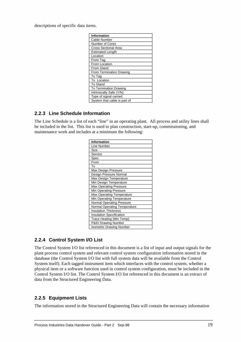
2.2.2 Cable Schedule Information
The Cable Schedule is a list of all cables used in the construction of an operating plant. Each cablein the plant, whether for power, communications, or other purposes, must be included in theschedule. This listing is used during both start-up and commissioning and as a troubleshooting andmaintenance tool. Refer to the Electrical and Telecommunications discipline sections for
Process Industries Data Handover Guide - Part 2 Sep-98 19
descriptions of specific data items.
Information Cable Number Number of Cores Cross Sectional Area Estimated Length Location From Tag From Location From Gland From Termination Drawing To Tag To Location To Gland To Termination Drawing Intrinsically Safe (Y/N) Type of signal carried System that cable is part of
2.2.3 Line Schedule Information
The Line Schedule is a list of each “line” in an operating plant. All process and utility lines shallbe included in the list. This list is used to plan construction, start-up, commissioning, andmaintenance work and includes at a minimum the following:
Information Line Number Size Service Spec From To Max Design Pressure Design Pressure Normal Max Design Temperature Min Design Temperature Max Operating Pressure Min Operating Pressure Max Operating Temperature Min Operating Temperature Normal Operating Pressure Normal Operating Temperature Insulation Thickness Insulation Specification Trace Heating (Min Temp) P&ID Drawing Number Isometric Drawing Number
2.2.4 Control System I/O List
The Control System I/O list referenced in this document is a list of input and output signals for theplant process control system and relevant control system configuration information stored in thedatabase (the Control System I/O list with full system data will be available from the ControlSystem itself). Each tagged instrument item which interfaces with the control system, whether aphysical item or a software function used in control system configuration, must be included in theControl System I/O list. The Control System I/O list referenced in this document is an extract ofdata from the Structured Engineering Data.
2.2.5 Equipment Lists
The information stored in the Structured Engineering Data will contain the necessary information
20 Sep-98 Process Industries Data Handover Guide - Part 2
and associations to enable suitable query tools to extract lists of particular types of information(e.g. the mechanical equipment list will include each piece of mechanical equipment in the facility.The Instrument List is a list of all instruments for an operating plant which includes all hardwareand relevant software as detailed in the P&ID’s).
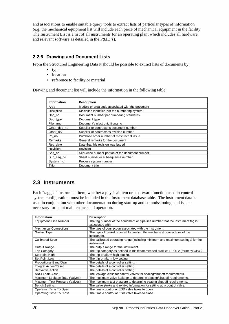
2.2.6 Drawing and Document Lists
From the Structured Engineering Data it should be possible to extract lists of documents by;• type• location• reference to facility or material
Drawing and document list will include the information in the following table.
Information DescriptionArea Module or area code associated with the documentDiscipline Discipline identifier, per the numbering systemDoc_no Document number per numbering standardsDoc_type Document typeFilename Document's electronic filenameOther_doc_no Supplier or contractor's document numberOther_rev Supplier or contractor's revision numberPo_no Purchase order number of most recent issueRemarks General remarks for the documentRev_date Date that this revision was issuedRevision RevisionSeq_no Sequence number portion of the document numberSub_seq_no Sheet number or subsequence numberSystem_no Process system numberTitle Document title
2.3 Instruments
Each “tagged” instrument item, whether a physical item or a software function used in controlsystem configuration, must be included in the Instrument database table. The instrument data isused in conjunction with other documentation during start-up and commissioning, and is alsonecessary for plant maintenance and operation.
Information DescriptionEquipment/ Line Number The tag number of the equipment or pipe line number that the instrument tag is
associated with.Mechanical Connections The type of connection associated with the instrument.Gasket Type The type of gasket required for sealing the mechanical connections of the
instrument.Calibrated Span The calibrated operating range (including minimum and maximum settings) for the
instrument.Output Range The output range for the instrument.Trip Category The trip category as defined in BP recommended practice RP30-2 (formerly CP48).Set Point High The trip or alarm high setting.Set Point Low The trip or alarm low setting.Proportional Band/Gain The details of a controller setting.Integral Action/Reset The details of a controller setting.Derivative Action The details of a controller setting.ANSI Leak Class The leakage class for control valves for sealing/shut off requirements.Maximum Leakage Rate (Valves) The maximum valve leakage to determine seating/shut off requirements.Maximum Test Pressure (Valves) The maximum test pressure to determine seating shut off requirements.Bench Setting The valve stroke and related information for setting up a control valve.Operating Time To Open The time a control or ESD valve takes to open.Operating Time To Close The time a control or ESD valve takes to close.
Process Industries Data Handover Guide - Part 2 Sep-98 21
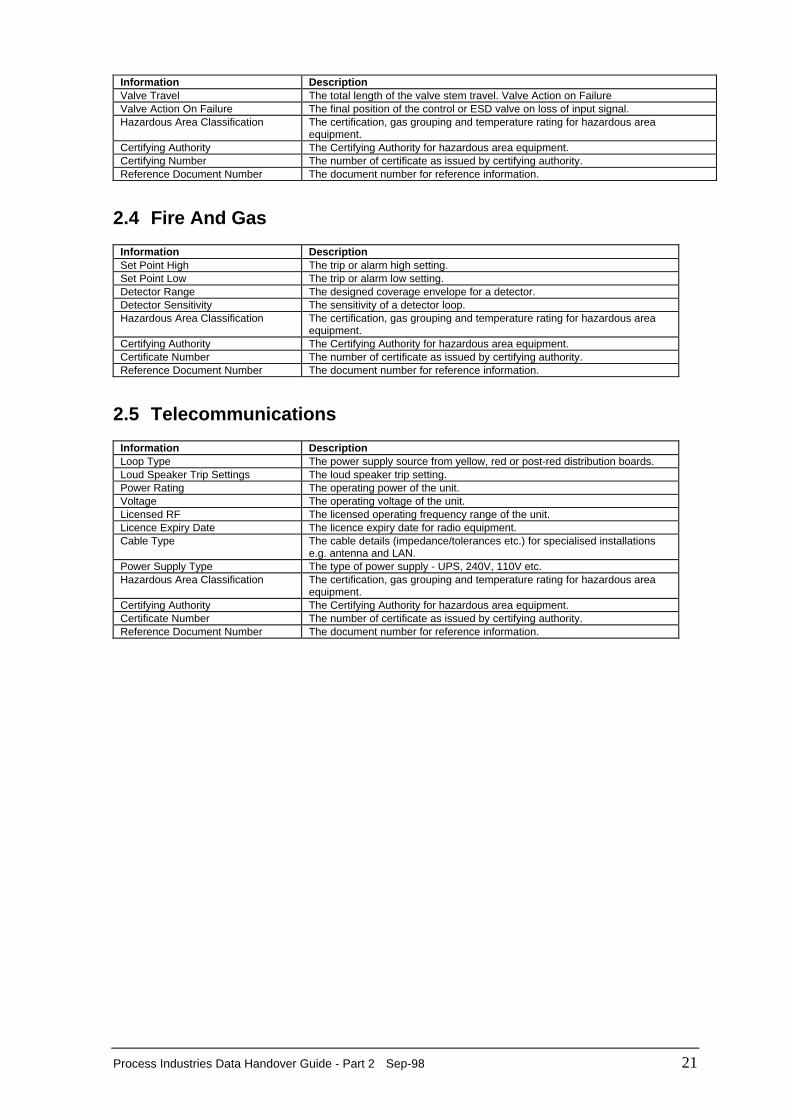
Information DescriptionValve Travel The total length of the valve stem travel. Valve Action on FailureValve Action On Failure The final position of the control or ESD valve on loss of input signal.Hazardous Area Classification The certification, gas grouping and temperature rating for hazardous area
equipment.Certifying Authority The Certifying Authority for hazardous area equipment.Certifying Number The number of certificate as issued by certifying authority.Reference Document Number The document number for reference information.
2.4 Fire And Gas
Information DescriptionSet Point High The trip or alarm high setting.Set Point Low The trip or alarm low setting.Detector Range The designed coverage envelope for a detector.Detector Sensitivity The sensitivity of a detector loop.Hazardous Area Classification The certification, gas grouping and temperature rating for hazardous area
equipment.Certifying Authority The Certifying Authority for hazardous area equipment.Certificate Number The number of certificate as issued by certifying authority.Reference Document Number The document number for reference information.
2.5 Telecommunications
Information DescriptionLoop Type The power supply source from yellow, red or post-red distribution boards.Loud Speaker Trip Settings The loud speaker trip setting.Power Rating The operating power of the unit.Voltage The operating voltage of the unit.Licensed RF The licensed operating frequency range of the unit.Licence Expiry Date The licence expiry date for radio equipment.Cable Type The cable details (impedance/tolerances etc.) for specialised installations
e.g. antenna and LAN.Power Supply Type The type of power supply - UPS, 240V, 110V etc.Hazardous Area Classification The certification, gas grouping and temperature rating for hazardous area
equipment.Certifying Authority The Certifying Authority for hazardous area equipment.Certificate Number The number of certificate as issued by certifying authority.Reference Document Number The document number for reference information.
22 Sep-98 Process Industries Data Handover Guide - Part 2
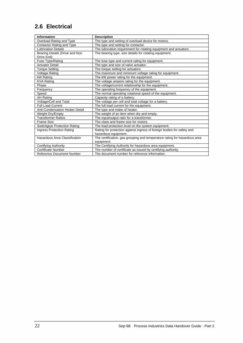
2.6 Electrical
Information DescriptionOverload Rating and Type The type and setting of overload device for motors.Contactor Rating and Type The type and setting for contactor.Lubrication Details The lubrication requirement for rotating equipment and actuators.Bearing Details (Drive and NonDrive End)
The bearing type, size details for rotating equipment.
Fuse Type/Rating The fuse type and current rating for equipment.Actuator Detail The type and size of valve actuator.Torque Setting The torque setting for actuators.Voltage Rating The maximum and minimum voltage rating for equipment.kW Rating The kW power rating for the equipment.KVA Rating The voltage ampere rating for the equipment.Phase The voltage/current relationship for the equipment.Frequency The operating frequency of the equipment.Speed The normal operating rotational speed of the equipment.AH Rating Capacity rating of a battery.Voltage/Cell and Total The voltage per cell and total voltage for a battery.Full Load Current The full load current for the equipment.Anti-Condensation Heater Detail The type and make of heater.Weight Dry/Empty The weight of an item when dry and empty.Transformer Ratios The input/output ratio for a transformer.Frame Size The class and frame size for motors.Switchgear Protection Rating The load protection level on the system equipment.Ingress Protection Rating Rating for protection against ingress of foreign bodies for safety and
hazardous equipment.Hazardous Area Classification The certification, gas grouping and temperature rating for hazardous area
equipment.Certifying Authority The Certifying Authority for hazardous area equipment.Certificate Number The number of certificate as issued by certifying authority.Reference Document Number The document number for reference information.
Process Industries Data Handover Guide - Part 2 Sep-98 23
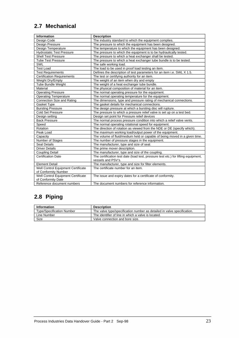
2.7 Mechanical
Information DescriptionDesign Code The industry standard to which the equipment complies.Design Pressure The pressure to which the equipment has been designed.Design Temperature The temperature to which the equipment has been designed.Hydrostatic Test Pressure The pressure to which the equipment is to be hydraulically tested.Shell Test Pressure The pressure to which a heat exchanger shall be tested.Tube Test Pressure The pressure to which a heat exchanger tube bundle is to be tested.SWL The safe working load.Test Load The load to be used in proof load testing an item.Test Requirements Defines the description of test parameters for an item i.e. SWL X 1.5.Certification Requirements The test or certifying authority for an item.Weight Dry/Empty The weight of an item when dry and emptyTube Bundle Weight The weight of a heat exchanger tube bundle.Material The physical composition of material for an item.Operating Pressure The normal operating pressure for the equipment.Operating Temperature The normal operating temperature for the equipment.Connection Size and Rating The dimensions, type and pressure rating of mechanical connections.Gasket Type The gasket details for mechanical connections.Bursting Pressure The design pressure at which a bursting disc will rupture.Cold Set Pressure The pressure to which a pressure relief valve is set up on a test bed.Design setting Design set point for Pressure relief devicesBack Pressure The normal process pressure condition into which a relief valve vents.Speed The normal operating rotational speed for equipment.Rotation The direction of rotation as viewed from the NDE or DE (specify which).Peak Load The maximum working load/output power of the equipment.Capacity The volume of fluid/medium held or capable of being moved in a given time.Number of Stages The number of pressure stages in the equipment.Seal Details The manufacturer, type and size of seal.Driver Details The prime mover description.Coupling Detail The manufacturer, type and size of the coupling.Certification Date The certification test date (load test, pressure test etc.) for lifting equipment,
vessels and PSV’s.Element Detail The manufacturer, type and size for filter elements.Well Control Equipment Certificateof Conformity Number
The certificate number for an item.
Well Control Equipment Certificateof Conformity Date
The issue and expiry dates for a certificate of conformity.
Reference document numbers The document numbers for reference information.
2.8 Piping
Information DescriptionType/Specification Number The valve type/specification number as detailed in valve specification.Line Number The identifier of line in which a valve is located.Size Valve connection and bore size.