Embed Size (px)
Citation preview
V050 SERIESD I R E C T I O N A L C O N T R O L V A L V E
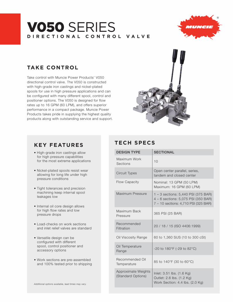
TAKE CONTROL
Take control with Muncie Power Products’ V050 directional control valve. The V050 is constructed with high-grade iron castings and nickel-plated spools for use in high pressure applications and can be configured with many different spool, control and positioner options. The V050 is designed for flow rates up to 16 GPM (60 LPM), and offers superior performance in a compact package. Muncie Power Products takes pride in supplying the highest quality products along with outstanding service and support.
KEY FEATURES• High-grade iron castings allow
for high pressure capabilities for the most extreme applications
• Nickel-plated spools resist wear allowing for long life under high pressure conditions
• Tight tolerances and precision machining keep internal spool leakages low
• Internal oil core design allows for high flow rates and low pressure drops
• Load-checks on work sections and inlet relief valves are standard
• Versatile design can be configured with different spool, control positioner and accessory options
• Work sections are pre-assembled and 100% tested prior to shipping
Additional options available, lead times may vary.
TECH SPECS
DESIGN TYPE SECTIONAL
Maximum Work Sections
10
Circuit TypesOpen center parallel, series, tandem and closed center
Flow Capacity Nominal: 13 GPM (50 LPM) Maximum: 16 GPM (60 LPM)
Maximum Pressure 1 – 3 sections: 5,440 PSI (375 BAR) 4 – 6 sections: 5,075 PSI (350 BAR) 7 – 10 sections: 4,710 PSI (325 BAR)
Maximum Back Pressure
365 PSI (25 BAR)
RecommendedFiltration
20 / 18 / 15 (ISO 4406:1999)
Oil Viscosity Range 60 to 1,360 SUS (10 to 300 cSt)
Oil Temperature Range
-20 to 180°F (-29 to 82°C)
Recommended Oil Temperature
85 to 140°F (30 to 60°C)
Approximate Weights (Standard Options)
Inlet: 3.51 lbs. (1.6 Kg) Outlet: 2.6 lbs. (1.2 Kg) Work Section: 4.4 lbs. (2.0 Kg)

0 10 20 30 40 50 60
0
3
7
10
14
0
50
100
150
200
0 3 6 9 12 15
1 WS
10 WS
PRESSURE DROP CURVES
Flow (GPM)
Open Center, Pressure to Tank (P-T)
Pressure to Work Ports (P-Ax/Bx)
Work Ports to Tank (Ax/Bx-T)
Flow (LPM)
Pre
ssur
e D
rop
(BA
R)
Pre
ssur
e D
rop
(PS
I)
P-T, 1 Work Section
P T
T
P-T, 10 Work Sections
P
0 19 38 57
0
3
7
10
14
0
50
100
150
200
0 5 10 15
1 WS
10 WS
P
Flow (GPM)
Flow (LPM)
Pre
ssur
e D
rop
(BA
R)
Pre
ssur
e D
rop
(PS
I)
A1 /B1A10 /B10
0 10 20 30 40 50 60
0
2
4
6
8
10
12
14
0
50
100
150
200
0 3 6 9 12 15
1 WS
10 WS
Flow (GPM)
Flow (LPM)
Pre
ssur
e D
rop
(BA
R)
Pre
ssur
e D
rop
(PS
I)
T
A10 /B10 A1 /B1

DIMENSIONS
1.89 [48] + # ofW.S. x 1.61 [41]
0.5113.0
1.8346.5
1.6141.0
1.6943.0
0.359.0
0.225.5
1.2832.5
1.5038.0
0.3910.0
2.0953.0
0.3910.0
0.318.0
1.6141.0
1.3434.0
0.6516.5
0.4511.4
Mounting Slots (4 Places) T2 PortPower Beyond PlugP/N = V050-C-PBS-04
“A” Port
“B” Port
P2 Port
2.4462.0
1.6141.0
2.6667.5
1.9950.5
0.359.0
0.39[10]
T1 Port (or Power
Beyond Port)
2.4863.0
3.8297.0
3.96100.5
3.7495.0
0.225.5
7
18° 18°
P1 Port
P2 Port
Standard R.V. Set @ 2,175 PSI (150 BAR)Adjustable from 1,175-2,900 PSI (81-200 BAR)Standard R.V. P/N V050-AB-N150
Position 0 = Neutral
Position 1 = Pressure Out “A” PortHandle “Out”Spool “IN”
Position 2 = Pressure Out “B” PortHandle “IN”Spool “OUT”
Spool Travel Total
Used For PowerBeyond Optoin
PORT SIZE AND TYPEINLET PORTS = -10 SAEWORK PORTS = -8 SAEOUTLET PORTS = -10 SAE x -8 SAEPOWER BEYOND PORT = -8 SAE

BACK-CAP OPTIONS CONTROL OPTIONS
⅛⅛
⅛
⅛
⅛
⅛
⅛
V050-BC-01Standard 3 Position, Spring Return
V050-BC-06Detent Spool “In”, Spring Spool “Out”
V050-BC-07Detent Spool “Out”, Spring Spool “In”
V050-BC-083 Position Detent
V050-BC-123 Position Spring Return with 4th position detent
V050-BC-33Pneumatic Shift, On/Off or Proportional(Use w/Control TypeAA, AE or AJ)
V050-BC-35 (Comes w/single acting spool “AB”)
V050-BC-36 (Comes w/double acting spool “AC”)
V050-BC-37 (Comes w/motor spool “AJ”) On/Off (Bang-Bang) Electrical Control (Use w/Control Type DE)
V050-CT-AAStandard Lever Cap Note: Handle lever not includedP/N for Handle: VLVH-01B-164
V050-CT-ABLever Cap for Float Spool (4th POS. Detent)Note: Handle lever not includedP/N for Handle: VLVH-01B-164
V050-CT-AESpool Cover forBack-cap Control
V050-CT-AJSpool Eye Only forDirect Connection(Spool End Not Part of Kit)
V050-CT-BGLow Pressure, Dual Sided, Hydraulic Control
21 0
2 10
21 0
2 10
21 0
21
0
21 0
2 10
3 21 0
3210
1
2
34
Connections1 - 2 = A Port1 - 3 = B Port(4 is an internal ground,no connection to 4needed)
1.6542.0
V050-CT-DELever Cap for electric shift Note: Handle lever not included P/N: VLVH-01C-133

MID SECTIONS
Section Type:B = Mid-section Relief Valve Adjustment Range:
See RV adjustment range in “Inlet Sections”
V050-B-FM-E53-N-150
Port Size & Type:FM = -10 SAE top and side
V050 Valve Series
Mid-section Type:E51 = Split flow mid-outlet*
E53 = Combined flow mid-inlet with RV
INLET RELIEF VALVESV050-AB-N-150
V050 Valve Series
Section Type:AB = Use with inlet and mid-section only
Relief Valve Setting (in BAR):See setting options in “Inlet Sections”
Relief Valve Adjustment Range: See RV adjustment range in “Inlet Sections”
INLET SECTIONS
Section Type:A = Inlet
V050-A-FM-7SX-N-150V050 Valve Series
Port Size & Type:FM = -10 SAE top and end
Inlet Options:7SX = Inlet with relief valve (standard)
8SX = Inlet without relief valve (plugged)
Relief Valve Setting: 150 = 2,175 PSI (150 BAR) XXX = No relief valve option (Use w/8SX option
Relief Valve Adjustment Range: B = 145 -1,160 PSI (10 - 80 BAR) N = 1,175 - 2,900 PSI (81 - 200 BAR) “N” is Standard Option R = 2,915 - 5,510 PSI (201 - 380 BAR) X = No relief valve (used w/8SX option)
*Split flow mid-outlet utilize 2 inlet sections on the valve assembly, and the mid-outlet acts as the outlet for each inlet
SPRING CODE B N R
Standard Settings 1,160 PSI (80 Bar) 2,175 PSI (150 BAR) 3,000 PSI (210 BAR)
OUTLETS
Section Type:C = Outlet
Additional Outlet Options:XXX = No options
V050-C-FL-3DX-XXX
Port Size & Type:FL = -8 SAE top x -10 SAE endFC = -8 SAE top & end (use w/power beyond option 6DX)
V050 Valve Series
Outlet Type:3DX = Standard outlet
6DX = Outlet with power beyond
(Part number for power beyond sleeve only: V050-C-PBS-04)
Relief Valve Setting:See setting options in “Inlet Sections”

MODEL NUMBER CONSTRUCTION
WORK SECTIONS
Special Features:X = No option (standard)
V050-AB -AA-01 FC-02-X
Spool Type:
AB = 3P3W, Single acting cylinder,
pressure out B port
AC = 3P4W, double acting cylinder
AJ = 3P4W, bi-rotational motor
AM = 4P4W, double acting cylinder w/float
(4th position detent)
V050 Valve Series
Control Type:AA = Handle control actuator (handle not included)*
AB = Lever cap for float spool “AM” (handle not included)*
AE = Spool cover for Back-Cap controls
AJ = Spool eye only for direct connection
BG = Low pressure hydraulic control
DE = Handle control actuator for electric shift
options 35, 36, and 37**
Back-cap Positioners & Controls:00 = No Back-Cap, used with “BG” control
01 = 3 position, spring return
06 = Detent spool IN, Spring spool OUT
07 = Detent spool OUT, Spring spool IN
08 = 3 position detent
12 = 3 position, spring return w/4th position detent
33 = Pneumatic positioning (on/off or proportional)
35 = On/Off (bang-bang) 12V electrical control for single
acting spool (use w/spool code AB)***
36 = On/Off (bang-bang) 12V electrical control for double
acting spool (use w/spool code AC)***
37 = On/Off (bang-bang) 12V electrical control for motor
` spool (use w/spool code AJ)***
Port Type
FC = -8 SAE
Work Port Options:02 = Machined w/steel plugs (standard)
RV Set @ 1,000 PSI (70 BAR) adjustable from 435-1,160 PSI (30-80 BAR)
03 = RV on A port, set at 1,000 PSI (70 BAR)
04 = RV on B port, set at 1,000 PSI (70 BAR)
05 = RV on A & B port, set at 1,000 PSI (70 BAR)
RV Set @ 1,800 PSI (125 BAR) adjustable from 1,175-2,900 PSI (81-200 BAR)
14 = RV on A port, set at 1,800 PSI (125 BAR)
15 = RV on B port, set at 1,800 PSI (125 BAR)
16 = RV on A & B port, set at 1,800 PSI (125 BAR)
Anti-cavitation Valves
11 = Anti-cav on A port
12 = Anti-cav on B port
13 = Anti-cav on A & B port
Note: Additional port accessory valve options available on request,lead times may apply)
* Handle kit to be ordered separately
Standard handle kit P/N: VLVH-01B-164
Length: 6.5" (164mm)
STUD KITS
V050 Valve Series
V050-T-01
T = Tie Rod
Number of Work Sections01-10 (1-10 Work Sections)
** Handle kit to be ordered separately
for electric shift lever cap “DE” P/N: VLVH-01C-133
“L”
“L”NO. OF WORK SECTIONS 1 2 3 4 5 6 7 8 9 10
“L” (in/mm) 4.59 / 116.5 6.20 / 157.5 7.81 / 198.5 9.43 / 239.5 11.04 / 280.5 12.66 / 321.5 14.27 / 362.5 15.88 / 403.5 17.50 / 444.5 19.11 / 485.5
Note: Torque to 22 lb.ft (30 Nm)
*** Option “35-37” must be used with Control Type “DE”

WORK PORT OPTIONS
Work Port Option:
W30 = Work Port RV
W33 = Work Port RV + Anti-Cav
W04 = Work Port Anti-Cav Only
WCX = Blanking Plug
Setting Range:
See RV adjustment range in “inlet sections”
X = No range, used w/ W04 or WCX)
V050 -W30 - N -1 25V250 Valve Series Relief Valve Setting (in BAR):
Standard Settings:
035 = 500 PSI
070 = 1,000 PSI
125 = 1,800 PSI
150 = 2,175 PSI
170 = 2,500 PSI
210 = 3,000 PSI
XXX = No Setting, used w/W04 & WCX
ORDER EXAMPLE PART NUMBER QTY. DESCRIPTION
V050-A-FM-7SX-N150 1 Inlet with relief valve
V050-AJ-AA-01-FC-02-X 2 Work section 1 & 2
V050-AC-AJ-01-FC-05-X 1 Work section 3
VLVH-01B-164 2 6.5” (164mm) handle kits for WS 1 & 2
V050-C-FL-3DX-XXX 1 Standard outlet
V050-T03 1 Stud kit for 3 section assembly
If you would like to order an assembled valve, you will need to order each item separately. The order in which parts are entered is how the valve will be built from left to right. On the right is an example of a 3 work section valve order:
W30 –RELIEF VALVE
THIS DRAWING IS THEPROPERTY OF
HYDRAFORCE INC. 500BARCLAY BOULEVARD,LINCOLNSHIRE. IL 60069.
AND IS LOANED SUBJECT TORETURN UPON DEMAND. IT
IS NOT TO BE REPRODUCEDOR USED DIRECTLY IN ANYWAY DETRIMENTAL TO THE
INTEREST OF HYDRAFORCE.HYDRAFORCE HYDRAULICSLTD IS A WHOLLY OWNED
SUBSIDIARY OFHYDRAFORCE INC.
HydraForce, Inc ®
Manifold Project2
Rev:By:Date:
RVCV56-20RVCV1?
RV08-29RV1?
W33 –R.V. + ANTI-CAV VALVE(Pilot Operated RV + Anti-Cav)
W04 –ANTI-CAV VALVE WCX –STEEL PLUG
THIS DRAWING IS THEPROPERTY OF
HYDRAFORCE INC. 500BARCLAY BOULEVARD,LINCOLNSHIRE. IL 60069.
AND IS LOANED SUBJECT TORETURN UPON DEMAND. IT
IS NOT TO BE REPRODUCEDOR USED DIRECTLY IN ANYWAY DETRIMENTAL TO THE
INTEREST OF HYDRAFORCE.HYDRAFORCE HYDRAULICSLTD IS A WHOLLY OWNED
SUBSIDIARY OFHYDRAFORCE INC.
HydraForce, Inc ®
Manifold Project1
Rev:By:Date:
CV04-20CV1

201 East Jackson Street • Muncie, Indiana 47305800-367-7867 • Fax 765-284-6991 • [email protected] • www.munciepower.com
Specifications are subject to change without notice. Visit www.munciepower.com for warranties and literature. All rights reserved. © Muncie Power Products, Inc. (2016)A Member of the Interpump Group
MP16-09 (Rev. 08-19)