Embed Size (px)
Citation preview

Western Electric 202
Installing an RC Network in the PhoneInstruction Manual – Publication 1002
This Telephone is Property of
____________________________________________________
____________________________________________________
Information on your Telephone – For Your Records
Manufacturer __________________________
Date of Original Manufacture _____________
Drawing Reference _____________________
_____________________________________
_____________________________________
_____________________________________
The Classic Handset Telephone
oldphoneguy.net
202
RC
V10
02
1002A
112
Col
inT.
Cha
mbe
rs–
202M
SW
41
This is the first desk telephone with a handset, E1,where the transmitter and receiver are combined. Laterversions used an updated modern handset, the F1, andhad an anti-sidetone network. The bell box in theoriginal was metal, later versions were smaller and hada plastic cover. Typical prices for this telephone arebetween $100 and $300, depending on age, conditionand degree of restoration.
Similar models were made by other manufacturers.
Original Western Electric Diagram101A Induction Coil

Notes
November 1, 2008
This is a metal phone, make sure NO wires comein contact with the metal case. Safety First!
oldphoneguy.net
112
This circuit can also be used on similar telephones including candlesticks
Introduction
All the models shown are similar in the wiring. The ringer box containedthe induction coil, either the “old” type or the more modern 101A coil. Aringer, with large gongs was also in the box. Old designs used just onecapacitor, which resulted in the bell being equivalent (in ringer load onthe phone line) to about 2 standard telephone bells. By the time youtake the different models and ringer boxes (there were several types ofthose) there are probably over 100 combinations.
Typically to make it work without the ringer box the receiver unit and thetransmitter unit are place in series. While it will work there are a lot ofannoying loud clicks and the magnet in the receiver unit is graduallyweakened (in most cases). Overall sound quality on a scale of 1 to 10,with 10 being with a ringer box and induction coil as designed, is abouta 4 or 5 at best with the series connection.
This project will use a simple circuit with a resistor and capacitor. On the10 scale it rates about a 7 or 7.5. It will be acceptable for most people.No ringer will be provided, it is assumed you have other phones on theline that ring.
You should refer to “Old Telephones – Building Testers and LearningHow to Use Them” on my web site: http://oldphoneguy.net. You candownload the book and print it. Some of the information in thisdocument is taken from that book.
First you should clean the telephone completely (a 50/50 mix of rubbingalcohol and Windex). Second clean all the electrical contacts, hookswitch and dial, the book explains how to use strips of index cardsdrawn between the contacts to remove the years of dirt and oxidation.Third, clean and lubricate the dial, this is also explained in the book.
You are going to build exactly what is in the rotary dial test set used bytelephone technicians in almost all telephone companies. That wasreplaced by a more modern tone version, but tens of thousands of therotary test sets served well for many years.

310
What Is In The Circuit?
This is the common test set. It is available on E Bay for about $20. Thesimplified circuit is shown next. .The line switch and the monitor capacitorare not show.
The only differences between this and the 202 are: A) the type oftransmitter and receiver (technically they are about the same), B) There isa varistor or click suppressor across the receiver (you can add one), andC) the dial shunt contact across the receiver is a contact that opens onthe dial in the 202.
U1 T1
Capacitor1.5 or 2.2 mFd
250 VDC
Resistor150 Ohm
1 Watt
Dial PulseContact Tel
Line
Dial ShuntContact
Links
My Web site: http://oldphoneguy.net
Parts source: http://www.alleclectronics.net
Wiring Diagrams: http://atcaonline.com/diagrams.html
Books
Fundamentals of Telephony – US Army Manual TM 11-678 Available on my website for free
Principles of Electricity as applies to Telephone and Telegraph Work Published by ATT, try http://www.abebooks.com
Old-Time Telephones – by Ralph Meyer Probably the best book on this subject with may old phones and wiring diagrams
Telephone Collectors Organizations
TCI - http://www.telephonecollectors.org/
ATCA – http://atcaoneline.com

94
Wiring Your Phone
For this project you will need:
2 Resistors 330 Ohms ½ Watt1 Capacitor 1 or 2.2 mFd 200 or 250 Volts
NON Polarized2 Diodes 1N4004 (click suppressor)Wire for the inside of the phone and a line cord
The resistors will be put in parallel, which will result in a 1 Watt resistorwith a resistance of 165 Ohms. The diodes will be put in parallel with theends reversed. Short wires will be attached to the parts to make it easyto wire.
Radio Shack does not carry a wide stock of parts. Find a localelectronics store, also disappearing at an alarming rate, or look at myweb site for links to mail order houses.
Shown above are the resistors, capacitor and diodes (varistorequivalent). After you add the short leads, cover the parts with electricaltape. There is plenty of room in the phone to put in the parts, you justneed to be creative on how you “attach” them so they do not becomeloose and rattle, tape will work well for that, but it may dry out in time.
Before going ahead, it might be best to build a simple project and dosome testing.
Helpful Hints and Notes
The “varistor” or 1N4404 diodes that are connected back to back areessential. This will prevent loud pops in your ear that may be causedby a variety of sources. They were not used on old telephones butare used on modern telephones and your ears have becomeaccustomed to them.
Dial pulse filters were often used. A “click” occurs when thetelephone line is opened and closed, this occurs when you dial anumber. A high voltage pulse was generated if an induction coil wasused. This probably will not happen with the RC Network but is is agood idea to install the filter.
You should be able to use this phone and another phone on the lineat the same time. That may not be possible if you had the originalringer box and induction coil.
The simple tester you built will provide talk power and if you wire yourphone correctly and you connect the tester to the wires on the modcord, you would be able to hear yourself talk, see the dial make theLED blink and the LED should go out when you hang up the phone.
I often refer to this as the QD Network, that stand for quick and dirty. Iworks well, is easy to set up and is low cost. Most telephonecollectors throw up their hands and tell you that you should have areal 100% authentic ringer box. Try this network for yourself andmake your own decision. You are going to spend less then if youbought a Big Mac at McDonalds, so your investment is small and youlearn something along the way.
Be sure to look at my website and real the information related to oldtelephones and download my book on old telephones and testers.Learning is life long.
The F1 handset has much better sound quality compared to the E1.
YBK
BBR
W
Pulse Contact
Dial
HA1 F1
F1 Handset
White
Black
Red
Capacitor
Resistor
Mod Plug
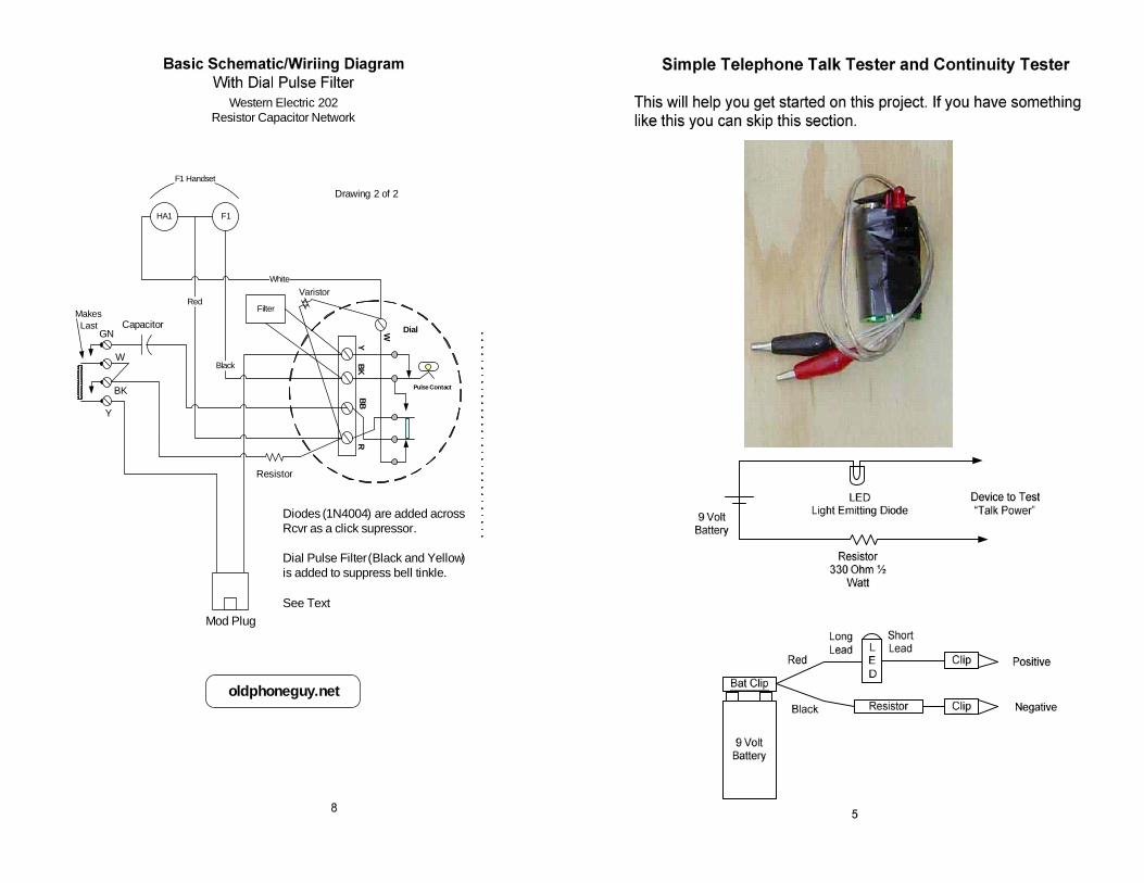
Diodes (1N4004) are added acrossRcvr as a click supressor.
Dial Pulse Filter(Black and Yellow)is added to suppress bell tinkle.
See Text
Western Electric 202Resistor Capacitor Network
oldphoneguy.net
Drawing 2 of 2
GN
W
BK
Y
MakesLast
Filter
Varistor

6 7
Parts List
9 Volt Alkaline Battery and matching Battery ClipLED – Almost any type of LED will workResistor – 330 Ohm ½ or ¼ watt (Orange, Orange, Brown, Gold)Clip Leads – Buy a package of 10 (you will use them later)
This is a simple tester and the battery life is not long, so do not use itfor extended “talk” testing.
If your not really an “electrical” type of person, test everything you canwith your new tester, light bulbs, toasters, TVs, Radios, try a 9 Voltradio (remove the original battery and use the tester as a source ofpower and see if the radio goes on and what happens when youreverse the leads on your tester), headsets (listen for the click), and soon. Just make sure everything is “unplugged” from its original powersource.
Remember, do not test anything that has a power source connected to it!
Test all parts of your 202, this includes the transmitter, receiver, hookswitch, dial contacts and cords. If you have another working telephoneput the tester across the line cord, you will be able to talk and listen. Ifthe telephone has a rotary dial you will see the LED blink as you dial.
YBK
BBR
W
Pulse Contact
Dial
HA1 F1
F1 Handset
White
Black
Red
Capacitor
Resistor
Mod Plug
Capacitor is 1 or 2.2 MFD, rated at200 or 250 VDC.
Resistor is 2 each 330 Ohmresistors in parallel for 160 Ohms
Western Electric 202Resistor Capacitor Network
oldphoneguy.net
Drawing 1 of 2
GN
W
BK
Y
MakesLast
Basic Schematic/Wiriing Diagram
The wire you use can be the original wires or you can replace it withjust about any type of wire. Spade tips on the wires will be nice butare not necessary. The Mod Cord can be a mode to spade cord orone that you cut one of the mod ends off of and strip the insulation offthe red and green wires.