Embed Size (px)
Citation preview

596 Vth Intemational Brick Masonry Conference
V-12. Brick Diaphragm WalI Structures--Design and Application W.G. Curtin, F.I.C.E., F.I.Struct.E., M.Cons.E.
(Senior Parlner, W.G. Curlin and Parlners)
ABSTRACT
The diaPhragm wall is simPly a wide cavity wall with lhe lwo leaves braced lry brick crossribs. The leaves and ribs form a series of connecled box beam5 giving lhe brickwork a massive increase in verlical and laleralload resislance compared lo lhe normal cavily wall.
The paper discusses lhe aUlhor's developmenl of lhe lechnique and lhe design philosophy and procedure. Examples are shown of lhe aPPlicalion lo lall single-slorey wide-span slruclures where lhe lechnique has proved competitive in cosi and speed of ereclion .againsl lhe alternalives of sleel or concrele framed slruclures clad with sheeling and insulalion. Twelve slruclures have been built lry lhe aulhor in lhe past len years in England and during lhal lime have been subjected to the worsl winds, hottest summer and wettesl aulumn on record, without distress. The lechnique has also been used for a mass relaining wall, where it showed cost and aesthelic advanlages over reinforced concrele. Olher applicalions are menlioned.
The paper briefly describes how lhe very encouraging results of lhe research work carried oul ai Liverpool University by the aulhor and Professor Sawko has slimulated lhe aUlhor's inleresl in furlher aPPlications of lhe melhod to multi-slorey and semi-rigid strnctures.
INTRODUCTION
The brick diaphragm wall is simply a wide cavity wall with the two leaves bonded together not by the normal cavity ties but by cross-ribs of brickwork. The leaves and crossribs, acting integrally, form a series of connected box or I sections having a high section modulus and radius of gyration. This gives the wall an impressive resistance to lateral and vertical loading. The technique enables such walls to be used for tall single-storey structures where experience and investigation has shown them to be faster, simpler and cheaper to construct than the traditional steel frame and cladding.
The paper discusses the development of the idea, its applications, the design philosophy and fUlure developments.
Development of the Diaphragm WalI Concept
The au thor 'stumbled' on the diaphragm purely by accident. He had designed a large school in load-bearing brickwork where much of the aesthetic appeal arose from the 'massing' of inter-connected plane surfaces of brick to the multi-storey and low-rise single-storey blocks. The only way to make the tall gymnasium walls a plane surface (then) was to have uneconomically thick walls. A possible solution was to have wide shallow piers to a cavily wall-this was unacceptable visually extemally and equally unacceptable internally beca use of the inconvenience it would cause to ball games. So the piers were positioned inside the cavity and the brick diaphragm was born! (See Fig. Ib).
The wall was still regarded as an equivalent piered wall for effective thickness, slenderness ratio, lateral resistance etc. It on ly slowly dawned on the authOl", the blindingly obvious, that the piers could be deepened and narrowed and the wall treated not as an equivalent piered wall but as the completely different concept ofthe box section. (See Fig. 2 and Plate 1)
The idea of the diaphragm is so sim pIe that many other engineers must have 'discovered' the technique and there is some evidence that the Victorian engineers may have used
the technique. The author was merely lucky to have realised its potentiaL
Advantages of Diaphragm WalIs
The application of diaphragm wall is mainly in 'shed' type structures, which accounts for ã high proportion of buildings in this country. The vast majority of such structures have their roofs supported on steel columns. The columns have to be enveloped by a cladding material and on occasions, the c1adding is backed up by an insulating material which in tum needs protecting by a hard lining. Frequently the c1adding, insulating and lining need a subsidiary steel framework to support them. The frame, c1adding, insulqtion and lining require maintenance (unlike brickwork) and lack brickwork's durability. The brick diaphragm forms not only the structural material but also the cladding, insulating and lining material. It has been found from experience, that brick diaphragms have always proved to be economical in capital cost (i.e. the cost to build). Accuracy in cost studies of construction is notoriously difficult to achieve and in a recent analysis of a hypothetical structure the diaphragm was found to be 4% more expensive to build l
. Within a short time of publication of the paper a comparison was made of actual jobs and the diaphragm technique was found to be 4% cheaper! There has been no detailed cost investigation to prove the practically certain fact that they have lower maintenance costs . Since brick is a good insulator, heating costs are lower, therefore, current costs (the cost to run the building) are also low. Diaphragm structures are thus financially cheap to build and economic to run. Experience has shown that it is a faster and simpler method of construction than the traditional steel frame. The saving in site time can be of the order of 30% and an even greater saving in pre contract time can be achieved2 • It has been found to give the architect much greater freedom, and scope in aesthetic treatment than the traditional 'tin shed'3.
Increase in testing, knowledge, experience and confidence in the technique could lead to other applications where

Session V, Paper 12, Brick Diaphragm Wall Structures-Design and Application 597
lateral loading is criticai and where low slenderness ratios are vital. As yet the technique is in its infancy and it is doubtful if its full potential has been appreeiated.
Some application of Diaphragm walls
Over the last thirteen years, the author's practice has designed sixteen diaphragm wall projects. During that time the structures have withstoorl the worst gales, hottest summers and wettest autumn on record and the reeent severe winter, without damage or distress. They were built to tight eost limits, there were no eonstruetion difficulties and they have required no maintenance, repair or decoration .
Some details and photographs of typieal applications are given below:-
Swimming Pool-Turton, Lancashire (Plates Nos. 2 and 3)
Client, Lancashire County Couneil. Architect, Charles Pearson and Sons.
The Architect decided to 'express the strueture' and the diaphragm wall was made deeper at the base and top of the wall than structurally necessary. This enabled the eross ribs to be projected, over a large depth of the wall, beyond the outer lear. This resulted in a bold modelling effect to the externai elevation. Internally the inner leaf has, in places, been stepped baek to form alcoves. The roof dadding is supported on preeast eoncrete beams.
Theatre-Salford (Plate No. 4) Client, Salford Players Architect, Wilson and Womersley
The Architect decided to extend the roof sheeting over the parapet and down the wall to make a 'cap' effect. The roof dadding is supported on steel lattice girders. This building is situated in a run-down area yet has suffered no attack or disfiguration by vandals.
Sports ComPlex-Oval, Bebington (Plate No. 5) Client, Bebington District Couneil Architect, Cheshire County Council
The central core of the complex is used for offiees, ehanging rooms, restaurants etc. On the western side are two swimming pools, with the roof supported on glu-Iam timber beams. On the eastern side is the main sports hall with its roof supported by steel castellated beams.
Sports Halt, Robins Lane, St. Helens Client, St. Helens Corporation Architect, ElIis Williams Partnership
This is the largest project built to date. The height from ground level to top of roof is 10m and the internai dimensions are 35 m X 37 m. Due to the large spans it was found economic to use a steel spaee frame for the roof (this is the largest space frame built in this country during the past few years).
Retaining Walt Freedom Gardens (Plate No. 6) Client, Ashton-under-Lyne Couneil Architect, Robert Shaw
These landscaped gardens were built on an olel elemolition site in the centre of the town to provide a social amenity. lt was first proposeel by the author to builel the retain ing walls in concrete with boarel-marked shuttering. However, the cost of shuttering, curveel on plan and varying in height, was exorbitant and it was eleeideel to use a filled diaphragm as a mass retaining wall. There was an abundance oI' elemolished brick and stonework on the site which would have been costly to 'cart away anel tip', and this was useel as the filling and grouted in. The result was a very cheap and attraetive retaining wall.
Sport Halt, Tomlinson School, Kearsley (Plate No. 7) Client, Lancashire County Council Architects, Hall anel Wilson
lt was deeided on this project to express the roof structure, resulting in a 'battlement' elevation at roor leveI. The main buttresses envelope the roor beams and the minor buttresses envelope the wind braeing. This is in contrast to the Turton School project where the wall structure was expressed.
Basic Design Assumptions
The design or diaphragm walls is rounded on a number of assumptions based in part on 'engineering judgment'. Probably the most important assumption is that such walls behave like box-sections (with integral action between the leaves and ribs}--unlike the normal eavity wall where such action cannot be considered.
Box-sections having a lower slenderness ratio and a higher section moduli than do plates oI' the same eross-sectional area can withstand greater axial and lateralloading. These assumptions were recently ehecked by research. 5
It was decided to commenee the testing work on the behaviour of the wall, as a strut, under axial loading. The load-bearing capacity of a strut is determined partly by its slenderness ratio. Ifthe diaphragm wall behaved like a boxsection then it would carry a greater axial load, because or its higher radius or gyration, than a conventional 'plate ' wall (i.e. a solid wall, cavity wall or a wall stiffened by piers). lt might also be more likely to 'crumple' under the load anel not bow or buckle like a plate.
Further, ir the wall did behave like a box-section it woulel give some indication that the concept of 'eJJective depth' useel in the Code might not be applicable to eliaphragm walls anel that instead consideration might be given to the use of the concept of radius of gyration.
If, too, the wall behaved like a box-section it would be capable oI' resisting a greater lateral load than a 'plate' wall or equivalent cross-sectional area, because oI' its greater section modulus.
The results of the research were very encouraging anel are discussed elsewhere.5
The Code's recommendations and the basic researeh on which it is founded were probably made with normal eavity walling only in mind. Therefore , the reeommenelations may not be fully applicable to walls with very wide cavities and the leaves structurally tied.
598
Design Principies and Method
The following. is an outline only of the design principies and method whlch have been used, since these are dealt with fully elsewhere.6
1. The wall is considered to act as a vertical box section. 2. The roofis designed to act as a horizontal plate member
to prop and tie the top of the walls and to transfer the wind load to transverse, or gable walls.
3. Capping beams of concrete are commonly used to: a. transfer the wind force on the wall into the roof
plate. b. provide an adequate factor of ~afety in 'tailing down'
against wind u plift on the roof. c. act, when necessary, as boom members of the roof
plate. d. assist in transferring the roof loads concentrically
to the wall . 4. The critical loading condition on the wall is considered
to be that due to combined dead and wind loading when the maximum uplift force on the roof and the maximum flexural tensile stress in the wall occurs. The compressive stresses due to combined dead and superlmposed loading or the combined dead, superimposed and wind loading conditions are generally so low that the choise of brick and mortar is inainly determined by the tensile resistance of the brickwork. Thus the design ofthe wall is governed by ilS required resistance to lateral forces and stresses due to wind.
5. The depth of the wall (i.e. spacing of leaves) is governed by: a. the section modulus necessary to withstand the ten
sile stresses due to bending. b. the slenderness ratio required to cope with the com
pressive stresses. c. the need to provide an adequate 'stability moment'.
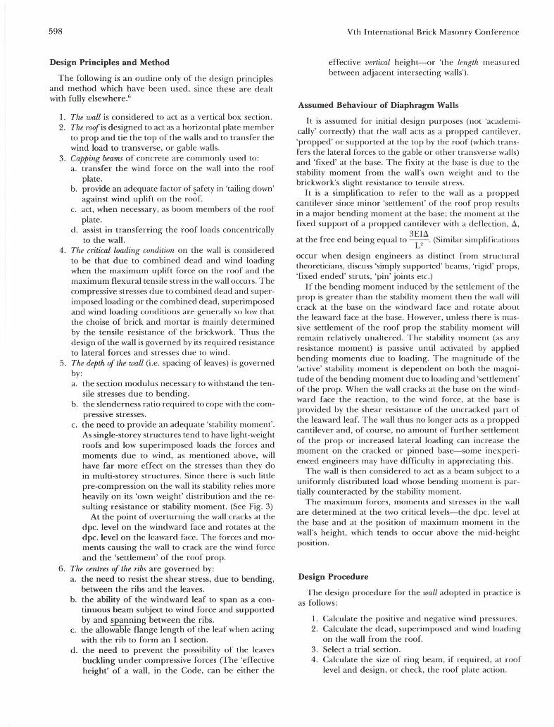
As single-storey structures tend to have light-weight roofs and low superimposed loads the forces and moments due to wind, as mentioned above, will have far more effect on the stresses than they do in multi-storey structures. Since there is such little pre-compression on the wall its stability relies more heavily on its 'own weight' distribution and the resulting resistance or stability moment. (See Fig. 3)
At the point of overturning the wall cracks at the dpc. levei on the windward face and rotates at the dpc. levei on the leaward face. The forces and moments causing the wall to crack are the wind force and the 'settlement' of the roof prop.
6. The centres of the ribs are governed by: a. the need to resist the shear stress, due to bending,
between the ribs and the leaves. b. the ability of the windward leaf to span as a con
tinuous beam subject to wind force and supported by and spanning between the ribs.
c. the allowable flange length of the leaf when acting with the rib to form an I section.
d. the need to prevent the possibility of the leaves buckling under compressive forces (The 'effective height' of a wall, in the Code, can be either the
Vth International Brick Masonry Conference
effective vertical height--or 'the length measllred between adjacent intersecting walls').
Assumed Behaviour of Diaphragm Walls
It is assumed for initial design purposes (not 'academically' correctly) that the wall acts as a propped cantilever, 'propped' or supported at the top by the roof (whích transfers the lateral forces to the gable or other transverse walls) and 'fixed' at the base. The fixity at the base is dlle to the st~bility moment from the wall's own weight and to the bnckwork's slight resistance to tensile stress.
It. is a sir:nplification to refer to the wall as a propped ~antllever smce minor 'settlement' or the roor prop reslllts m a major bending moment at the base; the moment at the fixed support of a propped cantilever with a deflection, ~,
h f· d b . 3EI~ at t e ree en emg equal to -U. (Similar simplífications
occur when design engineers as distinct from structllral theoreticians, discuss 'simply supported' beams, 'rígid' props, 'fixed ended' struts, 'pin'joints etc.)
Ir the bending moment induced by the settlement of lhe prop is greater than the stability moment then the wall will crack at the base on the windward face and rotate about the leaward face at the base. However, unless there is massive settlement of the roof prop the stability moment will re~ain relatively unaltered . The stability moment (as any reSlSt~nce moment) is passive until activated by applied bendmg moments due to loading. The magnitude of the 'active' stability moment is dependent on both the magnitude of the bending moment due to loading and 'settlement' of the prop. When the wall cracks at the base on the windward face the reaction, to the wind force, at the base is provided by the shear resistance of the uncracked part of the leaward leaf. The wall thus no longer acts as a propped cantllever and, of course, no amount of further settlement of the prop or increased lateral loading can increase the moment o.n the cracked or pinned base-some inexperienced engmeers may have difficulty in appreciating this. ~he wall i: t~en considered to act as a beam sllbject to a
~mformly dlstnbuted load whose bending moment is parttally counteracted by the stability moment.
The maximum forces, moments and stresses in the wall are determined at the two criticai levels-the dpc. levei al the base and at the position of maximum moment in the wall's height, which tends to occur above the mid-height position.
Design Procedure
The design procedure for the wall adopted in practice is as follows:
1. Calculate the positive and negative wind pressllres. 2. Calculate the dead, superimposed and wind loading
on the wall from the roof. 3. Select a trial section. 4. Calculate the size or ring beam, if required, at roor
levei and design, or check, the ruor plate action.

Session V, Paper 12, Brick Diaphragm Wall Structures-Design and Application 599
5. Determine the free bending moment due to wind,
p~", and the stability moment (W x ~, see Fig. 3) at
the base of the \Vali and compare. 6. Calculate lhe position and magnitude of lhe maxi
mum span wind moment and resislance moment, MR = (f, = f,) Z, of lhe wall and compare.
7. Check stresses at base of wall and at position of maximum span wind momento If, at the base a tensile stress did occur it would be necessary to check that this tensile stress does not exceed the permissible Slress at the dpc. Ir it does exceed the permissible stress, the section should be checked as a cracked section.
8. Choose brick and mortar. 9. Calculate the shear stress. I f the ribs are not bonded
to the leaves determine the lype and spacing of metal ties.
10. Check the stability of the transverse walls for roof plate reactions.
The Structural Design Assumptions
(The detailed design principies are dealt with elsewhere)5
1. That the roof loading is carried by the whole boxsection and not merely by the inner lear.
2. That, in the vertical plane, the wall behaves as a simplysupported box-beam under wind loading, with some fixity at the base of the wall due to its own weight.
3. The section modulus, radius of gyration etc., is taken for the whole box section and not on an equivalent cavity wall in accordance with the previous and new Code.
4. That, in the horizontal plane, the outer leaf only acts as a continuous beam under wind lateral force and that the inner leaf deflects as a result of lhe cross ribs' defleclion.
5. That the shear Slress distribution across the wall resulting from lateral loading is lhe same as for an I section.
6. That the effective height is equal to lhe actual height.
In addition to the above design assumptions lhere are a number of practical problems, for example:
1. LeaJlcross rib connections: On most contracts lhe cross ribs are bonded to the leaves but ties have also becn used to form the connection and the ou ter leaf can then be built in stretcher bond. It is possible that too many (or less likely, too few) ties are being used.
2. RooJlwall connection: On some contracts, space frame roofs have been used, on others trusses and on other castellated beams. It is obvious that a space frame will impose a more uniform load on the wall than a truss but the magnitude of the difference is unknown. Most diaphragms have been capped with a reinforced concrete beam which helps distribute the load uniformly. Nevertheless the wall must be, in practice, loaded eccentrically and non-uniformly but by how much is unknown.
3. Openings through walls: There must be access to the structure-door openings are necessary. (Service engineers would like to run the services through the cavity but access to the cavity would be necessary for repairs, maintenance and alleration of the services.) Openings in walls create stress concentralions which must be considered.
Comparison Between a 260 mm Thick Cavity Wall and a 450 mm Thick Cavity Diaphragm Wall
It is interesting to compare the vertical loadbearing capacity and the resistance LO lateral wind pressure of a 260 mm thick cavity wall and a 450 mm thick diaphragm wall of 6.0, effective height.
260 mm thick cavity wall
~ Q ~/ // 102.5 ~ ~~Ij~?=;l~?~~II[ 55 cavity.
Plano
pH2
8
102.5
3/sH
Consider axialload:
Slenderness ratio 6.0 x lO'
---=..:..::...-~=-=--- = 43.9 2/3 (102.5 + 102.5)
from BS 5628 - table 7 maximum slenderness ratio of 27 is exceeded therefore w = O
i.e. 260 mm cavity wall cannot carry any axial load when the effective height is 6.0 M and therefore the building of this height of wall, is prohibited in 260 mm cavity construction.
Consider lateralload: (taking minimum axial load)
Assume wall construction comprises bricks with a compressive strength of 27.5 N/mm2 and a water absorption of between 7% and 12% set in a grade (iii) mortar. (say 'Y .. = 2.5)
Properties of wall: (per M length of 2 leaves)
A
Z
x 0.1025 x 2
x 0.1025" x 2 6
fkx from BS 5628 table 3
3 Gk = 19 x 0.1025 x 2 x 8 x 6
0.205 M"
0.003502 M"
0.4 N/mm2
8.76 kN/M

600
@% H
Design ow = Gk x f = 8.76 x 0.9 = 7.85 kN/M.
@%H therefore:
also
fkx Design ow
)Im A
- 0.4 7.85 X lO"
2.5 0.205 x 1O';
- 0. 16 = 0.0383
EM = 0.693 kN.M
EM
0.693
= 9pH" 128
g X P x 6"
128
EM --
Z
EM x lO" 10" x
0.003502
- 0.286 EM
p 0.274 kN/I'vF = Design wind pressure
(and this depends upon the wall 's ability to clevelop lhe base
H") moment ofT
450 mm thick DiaPhragm Wall
Plan.
Wall properties: (per M length or wall)
A = [(0. 1025 x 0.245) + (2 x 0.1025 x 0.750)]
x 1000 = 0.2383 M" 750
[{0.75 :20.45"} _ {0.645 :20.245"}]
x 1000 = 0.00655 M' 750
Z = 0.00655 = 0.0146 M' 0.45
r = J± = 0.00655 = 0.166 M. 0.2383
Vth International Erick Masonry Conference
equivalent thickness oi' solid wall to give
, ~ 0166 M ~ J !:
C onsida axial load
0.166 =~ l = '\Iü.33T t = 0.575 M
6.0 x lO" Slenclerness ra tio = ---:-::-::---
450 13.33
assume e, = ° to 0.05 t therefore from BS 5628 Table 7
Design Vertical load
~ = 0.903
W = ~.A. fk !TI
Note: fk from table 2a BS 5628 = 7.1 N/mm"
W = 0.903 x 0.2383 x 10'; x 7.1 2.5 x lO"
Design verticalload W = 611 kN/M
Considel' lateml load (taking rninimum axial load)
. . h @ 3 23 19 Deslgn own welg t SH = O. 83 x
3 x - x 6 x 0.9
8
= 9. 17 kN/M
therefore:
fkx Design OW BM
'Y11l A Z
-0.4 + 9 .17 x 10" BM X --
2.5 0.2383 x 10 ,; 0.0146
-0.16 = +0.0385 - 0.0685 BM
EM = +2.898 kN/M
9 H" also BM = -p-
128
9 x P x 6" 2.898 = -~--
128
10l;
X 10"
P = 1.145 kN/M " = Design Wind pressure
Check conditions aI base for p = 0.81 kN/M"
H" base moment = p 8 -
MB = 1.145 x 6" 8
ME = 5. 153 kN/M

Session V, Paper 12, Brick Diaphragm Wall Structures-Design and Application 601
Stability moment of resistance
Stability moment of resistance is provided the own weight ofthe wall acting at a leverarm (la) produced by fully stressing the minimum width of rectangular stress block (see Figure 4) .
fk 7.1 - = - = 2.84 N/mm' 'Ym 2.5
Design ow at base = 0.2383 x 19 x 6 _ 24 I x 0.9 - .45 kN M
Minimum width of rectangular stress block
24.45 x 10' 1000 -x 2.84 = 8.61 mm
leverarm = 4~0 _ 8.:1 = 220.7 mm
Stability moment of resistance 24.45 x 0.2207 = 5.396 kN/M'
Therefore stability moment of resistance is greater than BM and the wall can resist p = 1.145 kN/M'
SUMMARY
260 mm thick cavity wall
Maximum axial load
Maximum design lateral Ioad (if wall could be constructed)
450 mm thick diaphragm wall
Maximum axial load
Maximum design lateral load
= ; zero kN /M
= 0.274 kN/m 2
= 611 kN/M
= 1.145 kN /M
The above comparison shows that, whilst the 260 mm thick cavity wall has no resistance to axial load at ali, the 450 mm diaphragm has a massive resistance , far in excess of that likely to arise from wide span lightweight roofs.
Even if the 260 mm cavity wall could stand, it would blow down in a fairly light breeze, whereas the 450 mm diaphragm wall could resist greater wind pressures than those to which buildings in this country are generally subject.
SUGGESTIONS FOR FUTURE TESTING
Although the results of research and experience are very encouraging there is, as always, need for further research. Some suggestions are given below:
I . Determination of behaviour at ultimate axial and lateral load. Too few tests have been carried out to predict with complete confidence, the behaviour under ultimate load.
It would be interesting to repeat the Redland test (6) on a wall built with lower strength bricks.
2. Elfective flange width and stress distribution in flange Despite the Code's recent doubling of width to 12t, which was the author's conservative estimate, there is need for detailed information since this affects rib spacing. The design of the leaf as a 'continuous beam'
supported by the ribs is a reasonable but unproven design assumption-an investigation of the stress distribution along the leaves would be valuable.
3. Shear across bricks at interface As far as the author knows, there is no research work recorded on the shear strength of bricks but only on the shear strength of brickwork. In walls the shear failure is along mortar joints but in diaphragms and fins 7
.B it could be across the bricks. Although in
diaphragms there is, in the author's opinion, a more than adequate excess of strength, he is concerned about shear failure in fin wall structures.
4 . Effect of depth of rib Ali of the author's diaphragms have been in the range of 2-3 deep brick walls. It has been shown thal a 3 brick depth is the maximum efficient depth .B An investigation to confirm this would be valuable. This would be particularly important in tall, free-standing diaphragms.
5. Effect of rib spacing Increase of rib spacing wou ld lead to overstressing and instability of the leaves, bUl would speeden and cheapen construction. At the moment, designers have to rely on experience and judgment in determining the rib spacing. It would be valuable to have experimentai data.
6. Elfect of relative stiffness of wall and roof The term 'prop cantilever' is an over simplicationthe wall acts as a simply supported beam panially fixed at the base due to its own weight. Ifthe suppon at the roof (the prop) is flimsy , it will 'settle' and deform laterally, and unexpectedly high compressive stresses might occur at the base of the wall.
7. Stress 'spread ' from capping beams In many diaphragms the capping beam is carried by the ribs only and thus acts as a concentrated load on the wall. Though there lIas been plenty of work clone on stress-spread in plane walls it is not known how rapidly it spreads in diaphragms. In practice the loacl on the rib cou ld be eccentric which woulcl complicate the stress clistribution.
8. Full sÍle testing Since the testing has been on model walls, the scale effect has to be taken into account in applying the work to actual structures. It woulcl be reassuring to
have confirmation of the predictions of scaling up. Testillg of tall walls would confirm the theoretical
analysis suggesting that the radius of gyration concept should be used and not the 'effective depth '9.
9. Combined loading No work has been done on combined axial and lateral loading. Though, from the tests, the effect of combinecl loading can be preclictecl, it would be useful to have confirmation from testing.
10. EccentTic loading The effect of eccentric loading can only be estimated-it is not known precisely what the effect woulcl be.
11 . Thermallnsulation To meet the new requirements of the D.O.E. the

602
insulation will have to be improved. There are a number of simple ways this could be done but they need investigating. The B.R.E. have done some valuable calculations, but so far no experiments have been carried out.
12. Shear Resistanee at D.P.C. Under lateral loading shear stress develops at the D.P.C. and information on the shear resistance would be helpful.
13. Maximum Height of the wall It is not known just how high these walls can be built. As a result of testing, the author would, Wilh confidence design taller structll.res than he has in the past, but without further testing designers would be unlikely to use the technique for very tall structures such as large aircraft hangars, international exhibition centres, big theatres, sportdromes etc.
14. Effeetive height of the wall The magnitude of the restraining effect of the capping beam or roof stiffness (and thus the effective height of the wall) is not known.
15. Effeet of OPenings Present design is based on estimates. (Ali design is, of course, based on estimates and assumptions but these are founded on factual evidence-and there is none for openings in diaphr~gms).
16. 'In-plane' lateralloading The roof plate action transfers the lateral wind force to the gable walls. No tests have been done on inplane forces on diaphragm walls, though it is likely that they have a high resistance to such forces.
17. Comparison of shear resistanee using: a. brick bonding b. cavity wall ties
18. Shear stress distribution across I seetion Brickwork is not a isotropic and homogenous material and it is not known if the shear stress due to
SA-bending does equal Ib
Y
19. Effeet of post-tensioning The author has proposed post-tensioning a diaphragm wall to counteract the effect of mining subsidence. The design will be based on experienceresearch is needed to reduce the probably conservative factor of safety .
20. Crane gantries Prujecting the cross-ribs through the inner leaf could provide a seating for the crane rails. Such crane loading would subject the wall to surge and sway forces and, at the moment, the wall's resistance can only be estimated.
21. Multi-storey struetures Any practising engineers, experienced in brick structures, will appreciate the applications of the technique to multi-storey structures. Until testing has been undenaken, such applications are likely to be ultracautious.
Floor slabs would be likely to be seated on the inner leaf only. Whilst this would eliminate the tiresome necessity to project the slabs over the outer leaf every
Vth International Brick Masonry Conference
third storey as in normal cavity walls it would eccentrically load the cavity wall. This creates a further need for the work mentioned in 10 above.
22. Semi-rigid struetures Preliminary feasibility studies show that, provided the leaves and ribs are reinforced to distribute load and stress from horizontal structural elements, semi-rigid structures are a distinct possibility.
23. Deformation of M ortars and dPe under 'knife-edge' Loading e01ídition. Rotation at base of diaphragms and fin walls will naturally produce deformation of the mortar or dpc whichever is the 'softer'. Though this is of minor interest (since only small deformation is necessary to
relieve stress concentration) the work would be useful in removing an unnecessary worry from the minds of the inexperienced.
Future Developments of Diaphragm Walls
It is usually difficult to forecast the future development of new ideas but some which have occurred to the author or are on his 'drawing board' are given below:
a. Industrial and Commercial The projects built so far have not been subject to bylaw approval. Since the previous and new Code do not deal with this type of wall the technique may not be 'deemed to satisfy' the building regulations. When the Code is funher revised there could be wide-spread applications in factories, garages, warehouses, supermarkets etc.4
b. Prestressing Because of the high ratio of section modulus to crosssectional area the wall is an ideal shape for prestressing. In the same way that a prestressed concrete I beam is more structurally and economically efficient than a solid rectangular concrete beam so is the diaphragm wall compared to anormal solid wall. A post tensioned diaphragm wall project will be constructed in 1979 for a structure which will suffer massive differential settlements due to mining subsidence.
c. Multi-storey Struetures The very high resistance shown by the walls-to vertical and lateral loading has stimulated the author to investigate their possibilities in some of his multi-storey 'frameless' structural projects.
d. Some other ApPlieations It is proposed or suggested to use a diaphragm wall for:
(i) permanent shuttering and cladding to the 'unacceptable face' of 'a reinforced concrete retaining wall.
(ii) a fire barrier in a tall, existing warehouse. (iii) a tall, free-standing boundary wall round an ex
clusive housing estate. (iv) a church to be built in noisy area where its acoustic
insulating qualities will be a bonus. (v) a noise barrier on inner city motorways.
(vi) a blast-resistant structural wall to a proposed factory adjacent to a chemical plant (afler the Flix-

Session V, Paper 12, Brick DiaPhragm Wall Structures-Design and Application 603
borough disaster it is a statutory obligation to design for blast-resistance where appropriate) .
(vii) a mass-retaining wall, where the voids are filled with grouted-in rubble.
e. Serni-Rigid Structures The very recent appreciation by the author of the possible new application of the stability moment concept for semi-rigid joints has led to preliminary feasibility studies-which look promising.
GUIDANCE TO ENGINEERS
It might appear imprudent to give advice to competent engineers as a result of a few buildings and some relatively unsophisticated tests but the test results give some confirmation of practical experience and the engineering assumptions andjudgments. Firmer advice can be given after the proposed full size test and the other tests outlined above, have been completed.
In the end, as always, the engineer has to make his own mind up, make decisions and carry lhe responsibility for those decisions. The following notes have been included in this paper in the hope that they may be of some help in the decision-making processo
I. Integral action There is firm evidence, both in the laboratory and on site, that there is integral action between the leaves and cross ribs.
2. Effective depth The effective depth certainly appears to be at least equal to the overall depth of the wall.
3. Rib Spacing For the time being, rib spacing should nor exceed twelve times the thickness of the leaves.
4. Section Modulus In determining the stresses under lateralloading, it is reasonable to take the section modulus of the wall as the section modulus of the 'box section' action and not merely as the sum of the section moduli of the two leaves. This is certainly applicable to one, two and possibly three brick deep cavities. Cavities of greater depth would almost certainly need stiffer (thicker) cross ribs than half brick one.
5. Slenderness Ratio When the wall has light lateral restraint from one side only, it would be prudent to consider the effective height as equal to the actual height. When there is light lateral restraint from both sides, a conservative choice of effective depth would be 0.9 times the actual height. This with an effective depth equal to the actual overall depth of lhe wall would give sufficiently low slenderness ratios to cause little concern in the overwhelming majority of present day applications of the technique.
6. Overall depth This would be governed by the need to provide an adequate section modulus to keep the stresses due to lateral loading within reasonable limits. The resulting depth of wall should then be checked for its capacity to resist vertical loading.
7. PropPing oj the top oj the wall If the roof acts as a wind reaction, it will carry load, thus creating stresses, strain
and therefore deflection of the roof. The roof must be stiff enough not to collapse (and normallightweight roofs have yet to collapse even under unprecedented wind loading). An estimate of the roof deflection may be made and its effect on the moment at the base of the wall determined. If the moment is less than the stability moment, the stresses in the brickwork at the base should be checked in detail. If the moment is greater than the stability moment then the stresses at the base should be checked for the 'cracked section' behaviour.
8 . SPecification and Supervision Provided that the brickwork is built to the normal good specification and supervised in the normal competent manner, the author sees no need for special consideration in this technique.
9. Rib/LeajConnection The author personally prefers cross bonding of the ribs and leafs and not the use of cavity ties. In view of the understandable present concern over the long term durability of cavity ties, the author could not, confidently, recommend their use-particularly for the outer leaf.
CONCLUSIONS
The success of the buildings in practice and the encouraging results of the preliminary research provide some evidence that the diaphragm wall technique is a viable, economic and attractive addition to the engineer's store of solutions in designing and building shed type structures.
Though the technique is in its infancy (and a lusty infant at that!) further experience, backed by research, suggest that there is potential for exciting developments.
BIBLIOGRAPHY
I. Humphries, D.M. and Curtin, W.G. 'Brick diaphragm wallsan alternative design for industrial buildings.' Journal of the Institute of Quantity Surveyors, Vol. 34, No. 10, 1978. 2. Curtin, W.G. and Harper, W. 'Construction ofbrick diaphragm walls for tall single-storey buildings.' Journal of the Institute of Building, Vol. 16, No. 6, 1978. 3. Curtin , W.G. and Bullen, P. 'Architectural treatment and building construction detailing of diaphragm walls' (in preparation). 4. Curtin, W.G. and Al-Hashimi , K. 'Design of brickwork in Industrial buildings.' Brick Development Association, pllblication May 1978. 5. Curtin, W.G. and Shaw, G. 'Brick diaphragm walls in tall singlestorey buildings.' Brick Development Association , PlIblicalion, No. 1977. 6. Curlin , Fowler and Sawko. 'Brick Diaphragm Wall Research.' Journal of the Institution of Structural Engineers (in preparation). 7. Curtin, W.G. and Thelwell, J .S. 'Brick fin walls' Journal of the Institute of Building, Vol. 16, No. 9, Sept. 1978. 8. Curtin, Shaw, Beck and Bray. 'Structural Design of fin walls for tall single-storey buildings' Brick Development Association publication, March 1979. 9. Sawko, F. and Curtin , W.G. 'Effective lhickness and structural efficiency of cellular walls and piers.' Proceedings, Institution of Civil Engineers, Part 2, December 1978.

604
r7 ;}( 7 v 7 7 7
(a) Piered Cavity Wall
7 z ;}( Z?
7 I (b) Piers Inside Cavity
(c) Diaphragm Wall
FiguTe 1.
Stability mcment cf resistance
; I M .~ I; 1" f .,f--450 ---+
FiguTe 4.
L " 102 mm ~ /
1-3 bricks /
r- 102 mm /
1
/ /
/ /
Vth International Brick Masonry Conference
o
~ ROOF PROP
CRACK '~ HINGE
/.
I
1-0 "2"
W STABILITY MOMENT = OWN WEIGHT OF WALL X ITS LEVER ARM
W X O
2
Figure 3.
1-1 .5m c/c
102.~
L 1
~
j
I
assumed box sectlon
FiguTe 2.

Session V, Paper 12, Brick Diaphragm Wall Structures-Design and Application 605
Plate 1. Diaphragm Wall under Construction Clay facings externalleaf, calcium silicates internai leaf. Sports hall for 5chool at Ormskirk.
Plate 2. Swimming Pool, Turton School, Bolton Cross ribs expressed externally.
Plate 3. Swimming Pool, Turton School, Bolton Roof structure is pre-cast concrete beams at 6 m centres supporting a domed roof light.
Plate 4. Salford Players Theatre

606 Vth International Brick Masonry Conference
Plate 5. Oval Sports Centre, Bebington Plate 7. Sports Halt, Tomlinson School, Keanley Castellated effect above capping beam . Roof in laminated timber beams at 3.6 m centres
with solid timber deck.
Plate 6. Mass Retaining Walt in Diaphragm Construction Freedom Gardens, Ashton-under-Lyne.